GENERAL INFORMATIONseries bars), the deck slab extension will have sufficient strength to resist...
31
VOL. V - PART 2 DATE: 11MAY2007 SHEET 1 of 31 INTEGRAL / JOINTLESS BRIDGES DECK SLAB EXTENSIONS GENERAL INFORMATION FILE NO. 20.04-1 GENERAL INFORMATION: This section of the chapter establishes the practices and requirements necessary for the design and detailing of deck slab extensions at abutments. For general requirements and guidelines see File Nos. 20.01-1 thru -5. The details shown in this section are intended only to provide the designer with the necessary detailing practices and requirements for the detailing of deck slab extensions. Concrete deck slab main and distribution reinforcement shall be detailed and placed in accordance with the requirements set forth in Chapter 10 except where otherwise noted in this section. Deck slab extensions shall be designed to resist the loads and forces to which the bridge deck system may be subjected. ES series bars shown in the details contained in this section shall be of the size and spacing required when combined with the deck slab distribution reinforcement (SL series bars), the deck slab extension will have sufficient strength to resist these loads and forces. Deflection of deck slab extension plus live load deflection of bearing assembly shall be limited to no more than one-half the thickness of the expanded rubber joint filler on top of backwall in order to prevent any upward forces being transmitted into the deck slab extension. Sample design calculations are included in File Nos. 20.04-5 thru 20.04-18 of this section to assist the designer in the design of deck slab extensions. Parapet/railing terminal walls shall be located on the superstructure. The end of slab shall be used as a reference line for the “Beginning of bridge” and “End of bridge” shown on the developed section along the centerline or baseline on the title sheet. End of slab shall be labeled on the deck slab plan. The back of backwall/stem shall be used as a construction/layout reference line on the plan view shown on the substructure layout, curved bridge layout, erection diagram the abutment details. Deck slab extension details shall be shown with the Deck Slab Plan, Deck Slab Elevations and Deck Slab Placement Schedule in the bridge plan assembly. Deck slab extension details shall be shown using phantom lines with abutment sections. For location of deck slab extension details in the bridge plan assembly, see File No. 01.02-4. The design and detailing of abutments for use with deck slab extensions is similar to that for abutments. For design and detailing of abutments, see Chapter 17. Wingwall haunches shall be designed to resist the moment and shear transferred through the rub plates. For details of abutment drains, see Chapter 22. On projects where the deck extension is utilized and an approach slab is required, then a buried approach slab shall be used. For details of buried approach slabs, see Chapter 19. Details of drainage details specific to using a buried approach slab with deck slab extension are included in this section.
Transcript of GENERAL INFORMATIONseries bars), the deck slab extension will have sufficient strength to resist...

VOL. V - PART 2 DATE: 11MAY2007 SHEET 1 of 31
INTEGRAL / JOINTLESS BRIDGES DECK SLAB EXTENSIONS GENERAL INFORMATION FILE NO. 20.04-1
GENERAL INFORMATION: This section of the chapter establishes the practices and requirements necessary for the design and detailing of deck slab extensions at abutments. For general requirements and guidelines see File Nos. 20.01-1 thru -5. The details shown in this section are intended only to provide the designer with the necessary detailing practices and requirements for the detailing of deck slab extensions. Concrete deck slab main and distribution reinforcement shall be detailed and placed in accordance with the requirements set forth in Chapter 10 except where otherwise noted in this section. Deck slab extensions shall be designed to resist the loads and forces to which the bridge deck system may be subjected. ES series bars shown in the details contained in this section shall be of the size and spacing required when combined with the deck slab distribution reinforcement (SL series bars), the deck slab extension will have sufficient strength to resist these loads and forces. Deflection of deck slab extension plus live load deflection of bearing assembly shall be limited to no more than one-half the thickness of the expanded rubber joint filler on top of backwall in order to prevent any upward forces being transmitted into the deck slab extension. Sample design calculations are included in File Nos. 20.04-5 thru 20.04-18 of this section to assist the designer in the design of deck slab extensions. Parapet/railing terminal walls shall be located on the superstructure. The end of slab shall be used as a reference line for the “Beginning of bridge” and “End of bridge” shown on the developed section along the centerline or baseline on the title sheet. End of slab shall be labeled on the deck slab plan. The back of backwall/stem shall be used as a construction/layout reference line on the plan view shown on the substructure layout, curved bridge layout, erection diagram the abutment details. Deck slab extension details shall be shown with the Deck Slab Plan, Deck Slab Elevations and Deck Slab Placement Schedule in the bridge plan assembly. Deck slab extension details shall be shown using phantom lines with abutment sections. For location of deck slab extension details in the bridge plan assembly, see File No. 01.02-4. The design and detailing of abutments for use with deck slab extensions is similar to that for abutments. For design and detailing of abutments, see Chapter 17. Wingwall haunches shall be designed to resist the moment and shear transferred through the rub plates. For details of abutment drains, see Chapter 22. On projects where the deck extension is utilized and an approach slab is required, then a buried approach slab shall be used. For details of buried approach slabs, see Chapter 19. Details of drainage details specific to using a buried approach slab with deck slab extension are included in this section.

VOL. V - PART 2 DATE: 11MAY2007 SHEET 2 of 31
INTEGRAL / JOINTLESS BRIDGES DECK SLAB EXTENSIONS GENERAL INFORMATION FILE NO. 20.04-2
GENERAL INFORMATION (Continued): The minimum depth of deck slab extension for steel beam/girder superstructures shall be 12”. Deck slab extension shall bear uniformly on the top of end diaphragm for design strength. On structure widths up to approximately 48', the designer shall connect the outside depths by a straight line, provided the maximum depth is not exceeded. Examples of deck extension on steel are shown on sheet 20.04-03. For structure widths greater than 48', the designer shall slope the backwalls parallel to top of deck maintaining the minimum depth. Designer has some flexibility in determining whether to design straight lined or to design parallel to cross slope. Other considerations in this determination would be the elevations at the outside edges of deck slab. Certain gradients and skews could increase or decrease these numbers and should be checked. The depth and size of diaphragms are additional factors in design.
Straight line design provides for easier construction. Less abutment elevations calculations are needed for design.
Parallel to cross slope provides for a more uniform design. Lower transverse forces are at the acute haunches. Smaller rub plates and smaller load applied to wing haunch may be additional considerations. The depth of deck slab extension shall not exceed 1’- 8”. Bottom of deck slab extension and top of abutment backwall shall be sloped parallel to finished grade of deck slab while maintaining the minimum depth of 12”. See transverse sections on sheet 20.04-4. The deck slab extends pass the back of backwall by four (4) inches. This dimension is affected by the thermal movement of the superstructure. The four (4) inches shall be set so that at 60 °F it is at the midpoint of its movement. For design/detailing check list for deck slab extensions, see File No. 20.04-22.

VOL. V - PART 2
Section on top of diaphragm near outside member.
Section shown at interior with straight line when deck slab depth less than diaphragm depth.
. Section shown at maximum thickness with straight line with slab depth less than diaphragm depth.
DATE: 11MAY2007 SHEET 3 of 31
INTEGRAL / JOINTLESS BRIDGES DECK SLAB EXTENSIONS GENERAL INFORMATION FILE NO. 20.04-3

VOL. V - PART 2
CROWNED DECK SLAB For use up to approximately 48’ width
CROWNED DECK SLAB For use when straight-line exceeds 1’-8” depth
SUPERELEVATED DECK SLAB
TRANSVERSE SECTIONS
DATE: 11MAY2007 SHEET 4 of 31
INTEGRAL / JOINTLESS BRIDGES DECK SLAB EXTENSIONS GENERAL INFORMATION FILE NO. 20.04-4

VOL. V - PART 2
SAMPLE DESIGN CALCULATIONS:
Given:
= 43.333 ft Bridge width out-to-out WBridge W = 40.000 ft Bridge width curb-to-curb clear L = 250 ft Total bridge length (2 span continuous steel plate girder) bridge L = 125 Span length at the abutment to be designed Span L = 125 ft Thermal movement length at the abutment to be designed thermal S = 9.333 ft Spacing of beams/girders (not along skew) beam Overhang = 3.000 ft Overhang Nb = 5 Number of beams/girders CS = 0.0208 Cross slope θ = 30° Skew angle
Soil, concrete, and steel properties:
γsoil = 145 pcf Unit weight of soil (use 145 for structural backfill) KP = 12 Passive earth pressure coefficient w = 150 pcf Unit weight of concrete Conc
DATE: 11MAY2007 SHEET 5 of 31
INTEGRAL / JOINTLESS BRIDGES DECK SLAB EXTENSIONS
SAMPLE DESIGN CALCULATIONS FILE NO. 20.04-5

VOL. V - PART 2
f’ = 4,000 psi Compressive strength of superstructure concrete cSuper f’ = 3,000 psi Compressive strength of substructure concrete cSub
'c
5.1concc f)w(33E =
= 3,834,000 psi Modulus of elasticity of concrete in superstructure EcSuper E = 3,321,000 psi Modulus of elasticity of concrete in substructure cSub Es = 29,000,000 psi Modulus of elasticity of steel fy = 60,000 psi Minimum yield strength of reinforcing steel n = 8 Modular ratio of superstructure super n = 9 Modular ratio of substructure sub F = 2,000 psi Maximum “galling stress” for ASTM A276 Type
316 steel, of which the rub plates are constructed. g
Δ = 60° Temperature range for expansion tExp Δ = 60° Temperature range for contraction tCont Δ = 120° Total temperature range for expansion/contraction t α = 6.5x10⁻⁶ per º F Coefficient of linear expansion for steel
Determine depth of deck extension:
Slab thickness = 8.5 in. Bolster thickness over support = 1.5 in. Top flange thickness at support = 0.75 in. Distance from bottom of top flange to top of end diaphragm = 3.0 in. Depth top of slab to top of end diaphragm/channel at exterior girder = 8.5 in + 1.5 in + 0.75 in + 3.0 = 13.75 in. Cross-slope times overhang = 3.0 ft (¼ in. per foot) = 0.75 in. Exterior edge of deck slab thickness = 13.75 in. – 0.75 in. = 13.0 in. Determine whether to design parallel to cross-slope or straight-line from exterior to exterior edge of deck slab. Cross-slope times distance from centerline to exterior deck = 21.67 ft (¼ in. per foot) = 5.42 in. Add to exterior edge of deck slab to get centerline depth = 13.0 in + 5.42 in = 18.42 in.
DATE: 11MAY2007 SHEET 6 of 31
INTEGRAL / JOINTLESS BRIDGES DECK SLAB EXTENSIONS
SAMPLE DESIGN CALCULATIONS FILE NO. 20.04-6

VOL. V - PART 2
Summary
For the example problem, assume that no additional considerations affect the design. The minimum and maximum depth requirements for deck slab extension with crown deck utilizing straight-line from exterior to exterior are met.
Exterior depth of deck = 13.0” > 12.0” OK Depth of deck at exterior diaphragm = 13.75” > 12.0” OK Centerline depth of deck = 18.42” < 20.0” OK
If design is parallel to cross-slope, the design depth is to top of diaphragm. Design depth would be 13.75”.
If straight-line method is utilized, the design depth is limited to the exterior depth of deck due to the cross-slope of the deck.
For ease of fabrication, use straight-line method with a design depth of 13.0”
Cover = 3.5 Distance to centerline of reinforcement d = 13.0 – 3.0 = 9.50 in.
TRANSVERSE SECTION
DATE: 11MAY2007 SHEET 7 of 31
INTEGRAL / JOINTLESS BRIDGES DECK SLAB EXTENSIONS
SAMPLE DESIGN CALCULATIONS FILE NO. 20.04-7

VOL. V - PART 2
Determine cantilever arm for moment and deflection design:
SLAB END DETAIL Overhang = 4.0 in Backwall thickness = 12.0 in To CL bearing = 12.0 in Total = 4.0 + 12.0 + 12.0 = 28.0 in = 2.33 ft Lever arm = 28/cos θ = 28/cos 30 = 32.33 in = 2.69 ft
Determine area of reinforcement required:
Moment and shear due to dead load weight of the deck slab extension:
= (13.0+18.42) (½) = 15.71 in = 1.31 ft havg
DATE: 11MAY2007 SHEET 8 of 31
INTEGRAL / JOINTLESS BRIDGES DECK SLAB EXTENSIONS
SAMPLE DESIGN CALCULATIONS FILE NO. 20.04-8
WDL = 150 lbs/ft3 (1.31 ft) = 196 lbs per square foot of slab
( )
2
ft2.69 ft
lbs196 22
2Lw 2×MDL = = = 713.0 ft-lbs per foot of slab
(2.69 ft)ft
lbs1962
= w x L = = 529.0 lbs per foot of slab VDL

VOL. V - PART 2
Moment and shear due to wheel load on deck slab extension:
For computing bending moment in foot pounds per foot for longitudinally reinforced slabs shall by:
)S(EP
DATE: 11MAY2007 SHEET 9 of 31
INTEGRAL / JOINTLESS BRIDGES DECK SLAB EXTENSIONS
SAMPLE DESIGN CALCULATIONS FILE NO. 20.04-9
Mw = (ft-lbs per foot of slab)
where P = 16,000 lbs (wheel load for HS20 loading)
Conservatively, E is set to equal 4.0 feet.
S = distance in feet from load to point of support (face of diaphragm)
= 2.33ft / cos 30° = 2.69 ft
( )=
4.0ft2.69lbs 16,000
ESP×Mw = = 10,776 ft-lbs per foot of slab
Assume live load impact fraction equal to 30%
= 1.30(10,776 ft-lbs) = 14,010 ft-lbs per foot of slab Mw+I = 1.30(16,000 lbs)/4.0 ft = 5,200 lbs per foot of slab Vw+I
Moment due to passive earth pressure:
( )( )23
ft1.30912ft
lbs14521
⎟⎟⎟
⎠
⎞
⎜⎜⎜
⎝
⎛ hK
21 2
ps ×××γqp = = = 1,492 lbs per foot of slab
⎟⎠
⎞⎜⎝
⎛−⎟
⎠
⎞⎜⎝
⎛3
in15.712
in15.71 = 2.62 in. e =
( )
ftin12
in2.62lbs1,492Mp = = eq p × = 326 ft-lbs per foot of slab

VOL. V - PART 2
The moment due to passive pressure induces additional deflection which can be converted to an effective P load, P . pVertical
P = M
DATE: 11MAY2007 SHEET 10 of 31
INTEGRAL / JOINTLESS BRIDGES DECK SLAB EXTENSIONS
SAMPLE DESIGN CALCULATIONS FILE NO. 20.04-10
pVertical p/Lever Arm = 326 ft-lbs/2.69 ft = 121 lbs per foot of slab
Total moment capacity required of the deck slab extension:
+ M + M = MMtotal DL w+I p = 713 ft-lbs + 14,010 ft-lbs + 326 ft-lbs = 15,049 ft-lbs per foot of slab
+ PPTotal = PDL w + PPVeritcal = 529 lbs + 5,200 lbs + 121 lbs =
= 5,850 lbs per foot of slab
Area of additional reinforcement required: As (provided by top distribution steel) = 0.19 in2 per foot of slab
As (provided by bottom distribution steel) = 0.19 in2 per foot of slab
Using the Bridge Concrete Section Analysis Program (trial and error) or alternative method, the total area of top reinforcement required, A (total required) = 0.88 in2 per foot of slab. s
2 As (additional required) = 0.88 in (total required) – 0.19 in2 (provided) 2 = 0.69 in per foot of slab
2 provided = 0.70 in per foot of slab). Therefore use #6 bars (ES series) @ 7.5” o/c max. (As
Maximum reinforcement size is limited to #6 bar size. Spacing shall not be less than four (4) inches.
Check deflection of section:
IE3LP
c
3Total
Load ××
×=Δ
+ Pwhere PTotal = PDL w + PPVeritcal = 5,850 lbs
L = 32.332 in (overhang length) E = 3,834,000 psi c I = moment of inertia

VOL. V - PART 2
For computing the moment of inertia for use in computation of deflections, Article 8.13.3 of the AASHTO specifications gives the following equation:
gIcrI aMcrM
1 gIaMcrM
eI33
≤×⎥⎥⎥
⎦
⎤
⎢⎢⎢
⎣
⎡
⎟⎟⎠
⎞⎜⎜⎝
⎛−+×⎟
⎟⎠
⎞⎜⎜⎝
⎛= AASHTO Eq. 8-1
'cf7.5 psi4,000f
DATE: 11MAY2007 SHEET 11 of 31
INTEGRAL / JOINTLESS BRIDGES DECK SLAB EXTENSIONS
SAMPLE DESIGN CALCULATIONS FILE NO. 20.04-11
r = = 7.5 = 474 psi
( )12
in13.0in 12 3
12hb 3×Ig = = = 2,197 in4
ftin12/
in6.875
4in2,197psi474⎥⎥⎦
⎤
⎢⎢⎣
⎡ ×
t
gr
yIf ×
Mcr = = = 13,361 ft-lbs
Ma = Mw = 15,049 ft-lbs
Icr = moment of inertia of cracked section transformed to concrete = 407 in4 (Bridge
Concrete Section Analysis Program) or alternative method.
=⎥⎥
⎦
⎤
⎢⎢
⎣
⎡
⎟⎟⎠
⎞⎜⎜⎝
⎛−+⎟⎟
⎠
⎞⎜⎜⎝
⎛= 4
34
3
e in474lbs-ft15,049lbs-ft13,3611in2,197
lbs-ft15,049lbs-ft13,361I 1,669 in4
Ie < Ig = 2,197 in4 Therefore, I = 1,660 in4
( )( )4
3
Load 1,660 inpsi3,834,000 3ftin 12 2.694 ft x5,850 lbs ⎟⎠⎞
⎜⎝⎛
=Δ
= 0.0104 in Conservatively, the cracked moment of inertia, 407 in4 could be used in the above equation. The resulting deflection is 0.042 in.
Deflection in bearing: The deflection of the bearing is also affected by the deflection of the live load applied. The compressive deflection and long term creep deflection shall be considered. The deflection of the cantilever is limited to one-half the thickness of the expanded rubber joint filler to prevent any significant upward forces to the deck extension. If the there is more than 0.25 inch deflection than the expanded rubber joint filler may be increase to 3/4 “ thickness.
Steel = 0.0 inches Laminated bearings = Live load deflection in bearings
VOL. V - PART 2
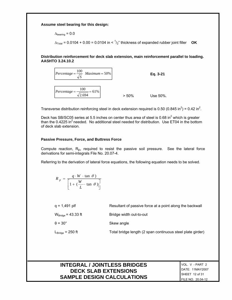
Assume steel bearing for this design:
= 0.0 Δbearing
DATE: 11MAY2007 SHEET 12 of 31
INTEGRAL / JOINTLESS BRIDGES DECK SLAB EXTENSIONS
SAMPLE DESIGN CALCULATIONS FILE NO. 20.04-12
ΔTotal = 0.0104 + 0.00 = 0.0104 in < 1/2” thickness of expanded rubber joint filler OK
Distribution reinforcement for deck slab extension, main reinforcement parallel to loading. AASHTO 3.24.10.2
Eq. 3-21 %50 ==
SPercentage 100 Maximum
%61 694.2
100==Percentage
> 50% Use 50%.
2Transverse distribution reinforcing steel in deck extension required is 0.50 (0.845 in ) = 0.42 in2.
Deck has SB/SC05 series at 5.5 inches on center thus area of steel is 0.68 in2 which is greater than the 0.4225 in2 needed. No additional steel needed for distribution. Use ET04 in the bottom of deck slab extension.
Passive Pressure, Force, and Buttress Force
Compute reaction, Rp, required to resist the passive soil pressure. See the lateral force derivations for semi-integrals File No. 20.07-4.
Referring to the derivation of lateral force equations, the following equation needs to be solved.
⎥⎦⎤
⎢⎣⎡ ⋅+
⋅⋅=
)tan(1
)tan
θ
θ
LW
WqR p
q = 1,491 plf Resultant of passive force at a point along the backwall W = 43.33 ft Bridge width out-to-out Bridge θ = 30° Skew angle L = 250 ft Total bridge length (2 span continuous steel plate girder) Bridge

VOL. V - PART 2
DATE: 11MAY2007 SHEET 13 of 31
INTEGRAL / JOINTLESS BRIDGES DECK SLAB EXTENSIONS
SAMPLE DESIGN CALCULATIONS FILE NO. 20.04-13
Rp = = 33,904 lbs ⎥⎦
⎤⎢⎣
⎡⎟⎠⎞
⎜⎝⎛+ tan(30)
25043.3331
n(30)3.333ft)ta1,491plf(4
The rub plates and wing haunch on the acute corners need to be designed to resist 33,904 lbs. If
abutments are not identical, the loading could be different for each abutment. Required Rub Plate Size:
Assume allowable galling stress, fg = 0.55Fg, = 0.55(2,000 psi) = 1,100 psi
Minimum plate size is 8 in x 6 in. x ½ in thick.
= slab exterior thickness – 3 in = 13.0 in – 3.0 in = 10.0 in Maximum height of plate, Hmax
Try 8 x 6 plate first.
)f(hR
g
pWmin = = ( )psi 1,100in6lbs 33,904 = 5.14 in
Thermal movement (expansion/contraction):
Thermal movement length shall be based on the two-thirds the total movement for 120 degrees temperature range. Rub plate size shall be sized for this movement length.
( ) ⎟⎠
⎞⎜⎝
⎛ ×°°ftin12ft125F120
32F per0.0000065thermaltL LΔΔ ××= α = = 0.78 in
= WWrequired min + ΔL = 5.14 in + 0.78 in = 5.92 in.
Therefore, use 8 in, the minimum. See File No. 20.04-27 for rub plate guidelines.

VOL. V - PART 2
Center the rub plates on edge of deck extension and wing haunch. Opposite corner takes all the expansion and the joint width may need to be increased to satisfy the transverse expansion of the superstructure.
DATE: 11MAY2007 SHEET 14 of 31
INTEGRAL / JOINTLESS BRIDGES DECK SLAB EXTENSIONS
SAMPLE DESIGN CALCULATIONS FILE NO. 20.04-14

VOL. V - PART 2
Design of wing haunch:
Extend wing haunch perpendicular to edge of deck slab sufficiently to handle RP equal to 33,904 lbs. Width of haunch design is 13.88 inches, Thus b = 13.88 in. Determine allowable shear stress carried by concrete in the wing haunch.
psi 000,3 95.0 f95.0 v 'cc == = 52.0 psi
Determine required d for concrete only to carry the applied load with 125% overstress allowed for Group IV loading.
v = bd(1.25)
RP
Solving for d
DATE: 11MAY2007 SHEET 15 of 31
INTEGRAL / JOINTLESS BRIDGES DECK SLAB EXTENSIONS
SAMPLE DESIGN CALCULATIONS FILE NO. 20.04-15
d = (1.25)bvR
c
p
5)2 psi)(1.213.88 in(533,904lbs = = 37.59 in.
Haunch depth required without stirrups, h, would be 37.59 in. + 3.0 in = 40.59 in. Section can be reduced with the use of stirrups to minimize the space required and the amount of concrete needed.

VOL. V - PART 2
Try a depth of haunch of 24.0 inches. This yields an approximate d = 24.0 in. – 3.0 in. = 21.0 in. Additional d value could be used if the sloped portion of the wing is considered in providing additional resistance in the case of elephant ear wings. However, it shall be ignored in this example.
bd(1.25)RP
21 in)1.2513.875 in(33,904 lbsv = = = 93.1 psi
v = v + vC S
DATE: 11MAY2007 SHEET 16 of 31
INTEGRAL / JOINTLESS BRIDGES DECK SLAB EXTENSIONS
SAMPLE DESIGN CALCULATIONS FILE NO. 20.04-16
Solving for vS vS = 93.1 – 52 = 41.1 psi
Therefore, stirrups required.
Shear reinforcement required by AASHTO 8.15.5.3.2 is given by
ssfbsv
AV = AASHTO Eq. (8-7)
bvfA
ssvSolving for s =
. Try #4 stirrups, AV = 0.4 sq. in.
in) psi(13.875 41.1i))(24,000psin (0.4 2
= 16.83 inches per AASHTO Eq. (8-7) and s =
#4 reinforcing steel.
'cf2AASHTO 8.15.5.3.8 requires that when v - v exceeds C the maximum spacing given in
Article 8.19 shall be reduced by one-half.
'cf2v - v = 41.1 psi < = 109.5 psi AASHTO 8.15.5.3.8 does not apply. C
Minimum shear reinforcement required by AASHTO 8.19.3 is given by
yw
fs50b
AASHTO Eq. (8-64) AV =

VOL. V - PART 2
w
yv
50bfA
Solving for s =
n.)50(13.875i0psi)in.)(60,00 sq. (0.4
DATE: 11MAY2007 SHEET 17 of 31
INTEGRAL / JOINTLESS BRIDGES DECK SLAB EXTENSIONS
SAMPLE DESIGN CALCULATIONS FILE NO. 20.04-17
smin = = 34.59 inches AASHTO 8.19.1 (minimum).
smax = 24.0 inches AASHTO 8.19.3. smax = 21.0/2 = d/2 = 10.5 inches AASHTO 8.19.3. Therefore, use #4 reinforcing stirrups at 10½ inches in wing haunch as a minimum.
Determine moment in wing haunch.
h = 13.00 inches Lever arm, y = 0.5 + h/2 = 0.5+13.0/2 = 7.0 inches Group IV loading allows for 125% overstress. Reduce load, RP by 1.25
RP = 33,904 lbs. /1.25 = 27,200 lbs (rounded up to nearest 100).
= 189,865 in-lb = 15,822 ft-lb =HaunchM yRp
Area of additional reinforcement required:
Using the Bridge Concrete Section Analysis Program (trial and error) or alternative method, the total area of reinforcement required, A (total required) = 0.40 in2
s for the wing haunch.

VOL. V - PART 2
Check minimum reinforcement per AASHTO 8.17
DATE: 11MAY2007 SHEET 18 of 31
INTEGRAL / JOINTLESS BRIDGES DECK SLAB EXTENSIONS
SAMPLE DESIGN CALCULATIONS FILE NO. 20.04-18
min ρs = = = 0.002027 60,0003,000
21241.7
2⎟⎠
⎞⎜⎝
⎛
y
c2
ff
dh1.7
′⎟⎠
⎞⎜⎝
⎛
Asc = ρs (bd) = 0.002027(13.88”)(21”) = 0.59 in2.
As < Asc, then check 4/3 As = 0.53 in2 < Asc, then use 4/3 As.
Try 3 - #4
2As provided = 0.60 in > 0.59 in2 OK
Locate the reinforcing steel at an effective d of 21.0 inches from the applied point of load.
Note: The above sample design calculations is for a two span continuous steel plate girder bridge. Design procedure is similar for a prestressed concrete beam bridge.


VOL. V - PART 2
CHECK LIST FOR DECK SLAB EXTENSIONS
1 Wing haunch at acute corner shall be designed to resist the moment and shear induced by
the force resulting from the passive earth pressure and the skew. Rub plates are only required at the acute corners of skewed bridges. Rub plates to be centered vertically and horizontally over contact area.
DATE: 11MAY2007 SHEET 22 of 31
INTEGRAL / JOINTLESS BRIDGES DECK SLAB EXTENSIONS - SLAB END DETAILS
CHECK LIST FILE NO. 20.04-22
2 Minimum thickness of the preformed joint filler between the backwall and the wing at the
obtuse corner shall be 1”. This may be increased due to thermal expansion in the transverse direction.
3 Extend wing 6” above finished grade. Not required for bridges without skew or where
terminal wall is on the substructure.
4 Top of rub plate to begin 11/2” below top of deck. Bottom of rub plate to maintain 11/2” clear from bottom of deck extension. Preformed joint filler to extend as shown.
5 Delete this note if railings are used or slip forming of parapets is not allowed.
6 Show plan and elevation view of deck slab extensions at a preferred scale of 3/8” = 1’-0”. The
elevation view should be projected down from the plan view. When bridge is not on skew and where sufficient room is available in elevation view, plan view is not required.
7 Label the location centerline/baseline as shown on the title sheet.
8 “End of slab” shall be used as the reference line for layout of deck slab extensions.
9 Label skew angle (if applicable).
10 The minimum width of backwall shall be 1’-0” for bridges without approach slabs and 1’-7” for
bridges with approach slabs. If approach slabs are a future possibility, the minimum width of backwall shall be 1’-7”.
11 The approach slab seat (7”) shall be provided on all deck slab extensions where future
possibility may require the addition of an approach slab.
12 Show sections taken through the deck slab extension at a preferred scale of 3/4” = 1’-0”. Coordinate the sections to provide the necessary details with repetition only where required.
13 Maximum spacing is 12”.
14 For instructions on completing the title block, see File No. 03.03.
15 For instructions on completing the project block, see File No. 03.02. 16 For instructions on developing the CADD sheet number, see File Nos. 01.01-7 and 01.14-4.
17 For general sheet order, see File No. 01.02-4.

VOL. V - PART 2
SLAB END DETAIL
The above detail shall be used where a deck extension on steel members is deemed appropriate.
1. Section is taken normal to the abutment face. Section is for slab details and shall be shown on the deck slab details sheets. Substructure details shall be shown on the abutment sheets.
2. The ½” expanded rubber joint filler shall extend the full length of the deck slab extension. 3. This dimension shall be determined by the designer and shown on the plans. 4. Provide dimension as necessary to maintain a 4” minimum overhang throughout the full
range of thermal movement.
DATE: 11May2007 SHEET 23 of 31
INTEGRAL /JOINTLESS BRIDGES DECK SLAB EXTENSIONS - SLAB END DETAIL
STEEL MEMBERS - NO APPROACH SLAB FILE NO. 20.04-23

VOL. V - PART 2
SLAB END DETAIL
The above detail shall be used where a deck extension on prestressed concrete members is deemed appropriate.
1. Section is taken normal to the abutment face. Section is for slab details and shall be shown on the deck slab details sheets. Substructure details shall be shown on the abutment sheets.
2. The ½” expanded rubber joint filler shall extend the full length of the deck slab extension. 3. This dimension shall be determined by the designer and shown on the plans. 4. Provide dimension as necessary to maintain a 4” minimum overhang throughout the full
range of thermal movement.
DATE: 11May2007 SHEET 24 of 31
INTEGRAL /JOINTLESS BRIDGES DECK SLAB EXTENSIONS - SLAB END DETAIL
PRESTRESSED MEMBERS - NO APPROACH SLAB FILE NO. 20.04-24

VOL. V - PART 2
SLAB END DETAIL
The above detail shall be used where an approach slab and deck extension on steel members are deemed appropriate. For details for drainage system, see sheet 20.04-29.
1. Section is taken normal to the abutment face. Section is for slab details and shall be shown
on the deck slab details sheets. Substructure details shall be shown on the abutment sheets. 2. The ½” expanded rubber joint filler shall extend the full length of the deck slab extension. 3. This dimension shall be determined by the designer and shown on the plans. 4. Provide dimension as necessary to maintain a 4” minimum overhang throughout the full
range of thermal movement.
DATE: 11May2007 SHEET 25 of 31
INTEGRAL / JOINTLESS BRIDGES DECK SLAB EXTENSIONS - SLAB END DETAIL
STEEL MEMBERS WITH APPROACH SLAB FILE NO. 20.04-25

VOL. V - PART 2
SLAB END DETAIL The above detail shall be used where an approach slab and deck extension on prestressed concrete members are deemed appropriate. For details for drainage system, see sheet 20.04-29.
1. Section is taken normal to the abutment face. Section is for slab details and shall be shown
on the deck slab details sheets. Substructure details shall be shown on the abutment sheets. 2. The ½” expanded rubber joint filler shall extend for the full length of the deck slab extension. 3. This dimension shall be determined by the designer and shown on the plans. 4. Provide dimension as necessary to maintain a 4” minimum overhang throughout the full
range of thermal movement.
DATE: 11May2007 SHEET 26 of 31
INTEGRAL / JOINTLESS BRIDGES DECK SLAB EXTENSIONS - SLAB END DETAIL
PRESTRESSED WITH APPROACH SLAB FILE NO. 20.04-26

VOL. V - PART 2
RUB PLATE DETAIL 4 plates required - 2 at each acute corner
Bridges on skews shall be provided with rub plates on the deck slab extensions. Rub plates are not required for bridges with skew = 0°.
The stainless steel plate shown above shall conform to the requirements of ASTM 276, Type 316.
Rub plates shall be designed to resist horizontal forces due to thermal induce passive earth pressures and to accommodate the travel due to thermal movements. For sample design calculations, see File Nos. 20.04-5 and -18.
Minimum size of rub plates shall be 8” (W) x 6” (H) x 1/2”. Hmax = depth of deck slab extension – 3” (11/2” concrete cover top and bottom of plate). Spacing of shear studs shall not exceed 6”.
Rub plates shall be centered vertically on the depth of the deck slab extension and horizontally on the contact area of the deck slab extension and the wingwall haunch.
Add appropriate note on the plan sheet for estimated quantities for cost of rub plates. For steel beams/girders, include cost in structural steel. For concrete beams, include cost in abutment concrete (Class A3).
DATE: 11May2007 SHEET 27 of 31
INTEGRAL / JOINTLESS BRIDGES DECK SLAB EXTENSIONS
RUB PLATE FILE NO. 20.04-27

VOL. V - PART 2
Terminal wall for deck extension shall be extended beyond the end of slab as shown above. For example partial details of terminal wall. See File No. 20.04-29. For details of drainage, see File No. 20.04-30 and -31. Note to designer: Terminal walls for parapet/railings shall extend 2'-3" beyond the end of slab extension and shall be deepened to the depth of the deck slab extension as shown. The deepened section assists in limiting the amount of erosion at the end of the deck slab. Remaining details shall be as shown on the parapet/railing system utilized.
DATE: 11May2007 SHEET 28 of 31
INTEGRAL / JOINTLESS BRIDGES DECK SLAB EXTENSIONS
TERMINAL WALL FILE NO. 20.04-28

VOL. V - PART 2
ELEVATION VIEW
PART PLAN TYPICAL FOR SKEWED CROSSING
PART PLAN TYPICAL FOR STRAIGHT CROSSING
DATE: 11May2007 SHEET 29 of 31
INTEGRAL / JOINTLESS BRIDGES DECK SLAB EXTENSIONS
TERMINAL WALL FILE NO. 20.04-29
VOL. V - PART 2
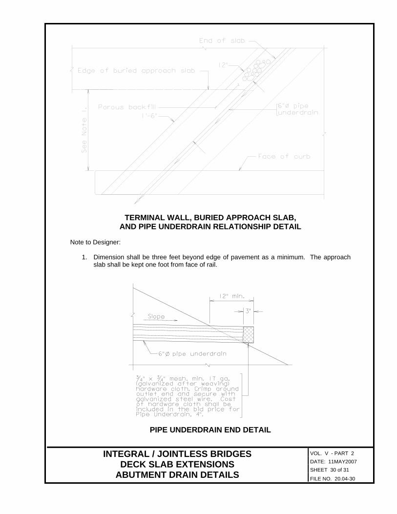
TERMINAL WALL, BURIED APPROACH SLAB, AND PIPE UNDERDRAIN RELATIONSHIP DETAIL
Note to Designer:
1. Dimension shall be three feet beyond edge of pavement as a minimum. The approach slab shall be kept one foot from face of rail.
PIPE UNDERDRAIN END DETAIL
DATE: 11MAY2007 SHEET 30 of 31
INTEGRAL / JOINTLESS BRIDGES DECK SLAB EXTENSIONS
ABUTMENT DRAIN DETAILS FILE NO. 20.04-30

VOL. V - PART 2 DATE: 11MAY2007 SHEET 31 of 31
INTEGRAL / JOINTLESS BRIDGES DECK SLAB EXTENSIONS
ABUTMENT DRAIN DETAILS FILE NO. 20.04-31
PIPE UNDERDRAIN NOTES TO BE PLACED ON PLANS (To be used only when buried approach slab is used) Pipe underdrain shall conform to the requirements of Section 232. The pipe underdrain shall follow the cross slope of the roadway over the approach slab. The pipe underdrain shall extend to 12" past the edge of the side slope and be located to provide free drainage away from the structure. The slope towards the side slopes shall be no less than two percent (2%). Porous backfill shall be placed around the pipe underdrain as detailed and as directed by the Engineer. The porous backfill shall extend 12” inches off the end of the deck extension over the buried approach slab and then 18" off the end of deck extension to the outside edge of wings. The porous backfill shall be paid for as Porous Backfill when it is a bid item and when porous backfill is not a bid item it shall be included in the bid price for the buried approach slab. The bid price shall be full compensation for all labor, tools, materials, equipment, and incidentals required for the satisfactory completion of the work. When a bid item, pipe underdrain will be measured in linear feet, complete-in-place and will be paid for at the contract unit price per linear feet. When not a bid item, pipe underdrain shall be included in the bid price for the buried approach slab.