General Purpose Relay MY - Farnell element14 Purpose Relay MY Ordering Information To Order: Select...
15
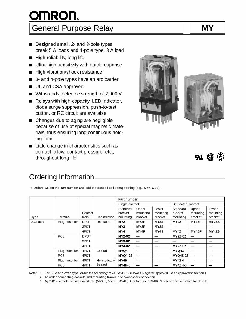
■ Designed small, 2- and 3-pole types break 5 A loads and 4-pole type, 3 A load ■ High reliability, long life ■ Ultra-high sensitivity with quick response ■ High vibration/shock resistance ■ 3- and 4-pole types have an arc barrier ■ UL and CSA approved ■ Withstands dielectric strength of 2,000 V ■ Relays with high-capacity, LED indicator, diode surge suppression, push-to-test button, or RC circuit are available ■ Changes due to aging are negligible because of use of special magnetic mate- rials, thus ensuring long continuous hold- ing time ■ Little change in characteristics such as contact follow, contact pressure, etc., throughout long life General Purpose Relay MY Ordering Information To Order: Select the part number and add the desired coil voltage rating (e.g., MY4-DC6). Part number Single contact Bifurcated contact Standard Upper Lower Standard Upper Lower Contact bracket mounting mounting bracket mounting mounting Type Terminal form Construction mounting bracket bracket mounting bracket bracket Standard Plug-in/solder DPDT Unsealed MY2 MY2F MY2S MY2Z MY2ZF MY2ZS 3PDT MY3 MY3F MY3S — — — 4PDT MY4 MY4F MY4S MY4Z MY4ZF MY4ZS PCB DPDT MY2-02 — — MY2Z-02 — — 3PDT MY3-02 — — — — — 4PDT MY4-02 — — MY2Z-02 — — Plug-in/solder 4PDT Sealed MYQ4 — — MYQ4Z — — PCB 4PDT MYQ4-02 — — MYQ4Z-02 — — Plug-in/solder 4PDT Hermetically MY4H — — MY4ZH — — PCB 4PDT Sealed MY4H-0 — — MY4ZH-0 — — Note: 1. For SEV approved type, order the following: MY4-SV-DC6. (Lloyd's Register approval. See “Approvals” section.) 2. To order connecting sockets and mounting tracks, see “Accessories” section. 3. AgCdO contacts are also available (MY2E, MY3E, MY4E). Contact your OMRON sales representative for details.
Transcript of General Purpose Relay MY - Farnell element14 Purpose Relay MY Ordering Information To Order: Select...
Designed small, 2- and 3-pole typesbreak 5 A loads and 4-pole type, 3 A load
High reliability, long life
Ultra-high sensitivity with quick response
High vibration/shock resistance
3- and 4-pole types have an arc barrier
UL and CSA approved
Withstands dielectric strength of 2,000 V
Relays with high-capacity, LED indicator,diode surge suppression, push-to-testbutton, or RC circuit are available
Changes due to aging are negligiblebecause of use of special magnetic mate-rials, thus ensuring long continuous hold-ing time
Little change in characteristics such ascontact follow, contact pressure, etc.,throughout long life
General Purpose Relay MY
Ordering InformationTo Order: Select the part number and add the desired coil voltage rating (e.g., MY4-DC6).
Part number
Single contact Bifurcated contact
Standard Upper Lower Standard Upper LowerContact bracket mounting mounting bracket mounting mounting
Type Terminal form Construction mounting bracket bracket mounting bracket bracket
Standard Plug-in/solder DPDT Unsealed MY2 MY2F MY2S MY2Z MY2ZF MY2ZS
3PDT MY3 MY3F MY3S — — —
4PDT MY4 MY4F MY4S MY4Z MY4ZF MY4ZS
PCB DPDT MY2-02 — — MY2Z-02 — —
3PDT MY3-02 — — — — —
4PDT MY4-02 — — MY2Z-02 — —
Plug-in/solder 4PDT Sealed MYQ4 — — MYQ4Z — —
PCB 4PDT MYQ4-02 — — MYQ4Z-02 — —
Plug-in/solder 4PDT Hermetically MY4H — — MY4ZH — —
PCB 4PDT Sealed MY4H-0 — — MY4ZH-0 — —
Note: 1. For SEV approved type, order the following: MY4-SV-DC6. (Lloyd's Register approval. See “Approvals” section.)2. To order connecting sockets and mounting tracks, see “Accessories” section.3. AgCdO contacts are also available (MY2E, MY3E, MY4E). Contact your OMRON sales representative for details.
2
MY MY
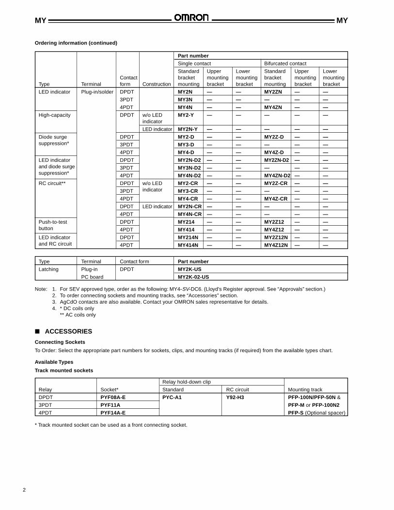
Ordering information (continued)
ACCESSORIES
Connecting Sockets
To Order: Select the appropriate part numbers for sockets, clips, and mounting tracks (if required) from the available types chart.
Available Types
Track mounted sockets
Relay hold-down clip
Relay Socket* Standard RC circuit Mounting track
DPDT PYF08A-E PYC-A1 Y92-H3 PFP-100N/PFP-50N &
3PDT PYF11A PFP-M or PFP-100N2
4PDT PYF14A-E PFP-S (Optional spacer)
* Track mounted socket can be used as a front connecting socket.
Part number
Single contact Bifurcated contact
Standard Upper Lower Standard Upper LowerContact bracket mounting mounting bracket mounting mounting
Type Terminal form Construction mounting bracket bracket mounting bracket bracket
LED indicator Plug-in/solder DPDT MY2N — — MY2ZN — —
3PDT MY3N — — — — —
4PDT MY4N — — MY4ZN — —
High-capacity DPDT w/o LED MY2-Y — — — — —indicator
LED indicator MY2N-Y — — — — —
Diode surge DPDT MY2-D — — MY2Z-D — —suppression* 3PDT MY3-D — — — — —
4PDT MY4-D — — MY4Z-D — —
LED indicator DPDT MY2N-D2 — — MY2ZN-D2 — —and diode surge 3PDT MY3N-D2 — — — — —suppression* 4PDT MY4N-D2 — — MY4ZN-D2 — —
RC circuit** DPDT w/o LED MY2-CR — — MY2Z-CR — —
3PDT indicator MY3-CR — — — — —
4PDT MY4-CR — — MY4Z-CR — —
DPDT LED indicator MY2N-CR — — — — —
4PDT MY4N-CR — — — — —
Push-to-test DPDT MY214 — — MY2Z12 — —button 4PDT MY414 — — MY4Z12 — —
LED indicator DPDT MY214N — — MY2Z12N — —and RC circuit 4PDT MY414N — — MY4Z12N — —
Note: 1. For SEV approved type, order as the following: MY4-SV-DC6. (Lloyd's Register approval. See “Approvals” section.)2. To order connecting sockets and mounting tracks, see “Accessories” section.3. AgCdO contacts are also available. Contact your OMRON sales representative for details.4. * DC coils only
** AC coils only
Type Terminal Contact form Part number
Latching Plug-in DPDT MY2K-US
PC board MY2K-02-US

3
MY MY
Solder Wire wrapterminal terminal Relay hold-down clip Socket Mounting Plate
Relay socket socket Standard Push-to-test RC circuit Mtg. plate 1 18 36
DPDT PY08 PY08QN PYC-P PYC-P2 PYC-1 PYC-S PYP-1 PYP-18 PYP-36
3PDT PY11 PY11QN
4PDT PY14 PY14QN
Back connecting sockets
Note: Types PYP-18, PTP-12 and PTP-10 may be cut to any desired length.
PC terminal Relay hold-down clip
Relay socket Standard Push-to-test RC circuit
DPDT PY08-02 PYC-P PYC-P2 PYC-1
3PDT PY11-02
4PDT PY14-02
Specifications
DPDT, 3PDT 4DPT High-capacity
Resistive load Inductive load Resistive load Inductive load Resistive load Inductive load(p.f. = 1) (p.f. = 0.4) (p.f. = 1) (p.f. = 0.4) (p.f. = 1) (p.f. = 0.4)
Load (L/R = 7 ms) (L/R = 7 ms) (L/R = 7 ms)
Rated load 5 A at 220 VAC 2 A at 220 VAC 3 A at 220 VAC 0.8 A at 220 VAC 7 A 220 VAC 3.5 A 220 VAC5 A at 24 VDC 2 A at 24 VDC 3 A at 24 VDC 1.5 A at 24 VDC 7 A 24 VDC 3.5 A 24 VDC
Contact material Ag Ag (Au Flash) AgCdO
Carry current 5 A 3 A 1 A 3 A 7 A
Max. operating 250 VACvoltage 125 VDC
Max. operating 5 A 1 A 3 A 7 Acurrent
Max. switching 1,100 VA 440 VA 660 VA 176 VA 1,540 VA 770 VAcapacity 120 W 48 W 72 W 36 W 168 W 84 W
Min. permissible Standard type: 1 mA, 5 VDC Standard and high sensitivity types: 100 µA, 1 VDC1 mA, 1 VDC
load (see note) Bifurcated type: 100 µA, 1 VDC
CONTACT DATA
Non-latching – Unsealed
Sealed, 4PDT Hermetically sealed, 4DPT
Resistive load Inductive load Resistive load Inductive load(p.f. = 1) (p.f. = 0.4) (p.f. = 1) (p.f. = 0.4)
Load (L/R = 7 ms) (L/R = 7 ms)
Rated load 1 A at 220 VAC 0.5 A at 220 VAC 3 A at 110 VAC 0.8 A at 110 VAC1 A at 24 VDC 0.5 A at 24 VDC 3 A at 24 VDC 1.5 A at 24 VDC
Contact material Ag (Au Flash)
Carry current 1 A 3 A
Max. operating 250 VAC 125 VACvoltage 125 VDC 125 VDC
Max. operating 1 A 3 Acurrent
Max. switching 220 VA 110 VA 330 VA 88 VAcapacity 24 W 12 W 72 W 36 W
Min. permissible Standard and high sensitivity types: 1 mA, 1 VDCload (see note) Bifurcated type: 100 µA, 1 VDC
Non-latching – Sealed/Hermetically sealed
Note: P level: λ60 = 0.1 x 10⁻⁶/operation

4
MY MY
Rated Rated current (mA) Pick-up Dropout Maximum Power consumptionvoltage Set coil Reset coil Coil resistance (Ω) voltage voltage voltage (VA, W)(V) 50 Hz 60 Hz 50/60 Hz Set coil Reset coil (% of rated voltage) Set coil Reset coil
6 146 142 68 13 32 80% max. 80% max. 110% max. Approx. Approx.
12 57 56 39 72 130 0.60 to 0.90 0.20 to 0.50
24 27.40 26.40 18.60 320 550
50 14 13.40 3.50 1,400 3,000
120 15.80 5.60 3.50 8,300 3,000
Latching – AC
Coil inductanceCoil (ref. value) (H) Pick-up Dropout Maximum Power
Rated Rated current (mA) resistance Armature Armature voltage voltage voltage consumptionvoltage (V) 50 Hz 60 Hz (Ω) OFF ON (% of rated voltage) (VA, W)
6 214.10 183 12.20 0.04 0.08 80% max. 30% min. 110% max. Approx.
12 106.50 91 46 0.17 0.33 1.00 to 1.20
24 53.80 46 180 0.69 1.30
50 25.70 22 788 3.22 5.66
100/110 11.70/12.90 10/11 3,750 14.54 24.60 Approx.
110/120 9.90/10.80 8.40/9.20 4,430 19.20 32.10 0.90 to 1.10
200/220 6.20/6.80 5.30/5.80 12,950 54.75 94.07
220/240 4.80/5.30 4.20/4.60 18,790 83.50 136.40
COIL DATA
Non-latching – AC
Note: 1. The rated current and coil resistance are measured at a coil temperature of 23°C (73°F) with tolerances of +15%, -20% forAC rated current, and ±15% for DC rated coil resistance.
2. The AC coil resistance and inductance are reference values at 60 Hz.3. The performance characteristics are measured at a coil temperature of 23°C (73°F).4. Because the coil is designed for low power consumption, connect a bleeder (if necessary after confirming the leakage
current), when the coil is driven by an SCR.5. For AC type latching coils, the rated current values are half-wave rectified current values measured with a DC ammeter.
Coil inductanceCoil (ref. value) (H) Pick-up Dropout Maximum Power
Rated resistance Armature Armature voltage voltage voltage consumptionvoltage (V) Rated current (mA) (Ω) OFF ON (% of rated voltage) (VA, W)
6 150 40 0.17 0.33 80% max. 10% min. 110% max. Approx.
12 75 160 0.73 1.37 0.90
24 36.90 650 3.20 5.72
48 18.50 2,600 10.60 21.00
100/110 9.10/10 11,000 45.60 86.20
Non-latching – DC
Rated Rated current (mA) Pick-up Dropout Maximum Power consumptionvoltage Set coil Reset coil Coil resistance (Ω) voltage voltage voltage (VA, W)(V) 50/60 Hz 50/60 Hz Set coil Reset coil (% of rated voltage) Set coil Reset coil
6 230 100 26 60 80% max. 80% max. 110% max. Approx. Approx.
12 110 50 110 235 1.30 0.06
24 52 25 470 940
Latching – DC

5
MY MY
Contact resistance 50 mΩ max.
Operate time 20 ms max.
Release time 20 ms max.
Operating frequency Mechanically 18,000 operations/hour
Under rated load 1,800 operations/hour
Insulation resistance 100 MΩ min. (at 500 VDC)
Dielectric strength Single contact type Unsealed: 2,000 VAC, 50/60 Hz for 1 minute1,000 VAC, 50/60 Hz for 1 minute between contacts of same polarity
Sealed: 1,500 VAC, 50/60 Hz for 1 minute1,000 VAC, 50/60 Hz for 1 minute between contacts of same polarity
Hermetically sealed: 1,000 VAC, 50/60 Hz for 1 minute700 VAC, 50/60 Hz for 1 minute between contacts of same polarity
Bifurcated contact type 1,500 VAC, 50/60 Hz for 1 minute1,000 VAC, 50/60 Hz for 1 minute between non-continuous contacts
Vibration Mechanical durability 10 to 55 Hz, 1.00 mm (0.04 in) double amplitude
Malfunction durability 10 to 55 Hz, 1.00 mm (0.04 in) double amplitude
Shock Mechanical durability 1,000 m/s2 (approx. 100 G)
Malfunction durability 200 m/s2 (approx. 20 G)
Ambient temperature Operating Unsealed: -55° to 70°C (-67° to 158°F)Sealed: -55° to 60°C (-67° to 140°F)Hermetically sealed: 25° to 60°C (77° to 140°F)
Humidity 35% to 85% RH
Service Life Mechanically Single contact type:AC: 50 million operations min. (at operating frequency of 18,000 operations/hour)DC: 100 million operations min. (at operating frequency of 18,000 operations/hour)
Mechanically Bifurcated contact type:AC: 50 million operations min.DC: 20 million operations min. (5 million operations for the sealed/hermeticallysealed types) (at operating frequency of 1,800 operations/hour)
Electrically See “Characteristic Data”
Weight Sealed/unsealed: Approx. 35 g (1.23 oz)Hermetically sealed: Approx. 50 g (1.76 oz)
CHARACTERISTICS
Non-latching
Note: Data shown are of initial value.
Contact resistance 50 mΩ max.
Operate time AC: 30 ms max.; DC: 15 ms max.
Release time AC: 30 ms max.; DC: 15 ms max.
Operating frequency Mechanically 18,000 operations/hour
Under rated load 1,800 operations/hour
Insulation resistance 100 MΩ min. (at 500 VDC)
Dielectric strength 1,500 VAC, 50/60 Hz for 1 minute1,000 VAC, 50/60 Hz for 1 minute between contacts of same polarity, and betweenset and reset coils
Vibration Mechanical durability 10 to 55 Hz, 1.00 mm (0.04 in) double amplitude
Malfunction durability 10 to 55 Hz, 1.00 mm (0.04 in) double amplitude
Shock Mechanical durability 1,000 m/s2 (approx. 100 G)
Malfunction durability 200 m/s2 (approx. 20 G)
Ambient temperature Operating -55° to 70°C (-67° to 158°F)
Humidity 45% to 85% RH
Service Life Mechanically 100 million operations min. (at operating frequency of 18,000 operations/hour)
Electrically See “Characteristic Data”
Weight Approx. 30 g (1.06 oz)
Latching

6
MY MY
CHARACTERISTIC DATA
Maximum switching capacity – Non-latching
MY2, MY3 MY4 MY4(Z)H MYQ4(Z)H
Electrical service life
MY2, MY3 (Resistive load) MY2, MY3 (Inductive load) MY4 (Resistive load) MY4 (Inductive load)
Rat
ed o
pera
ting
curr
ent
(A)
Rat
ed o
pera
ting
curr
ent
(A)
Rat
ed o
pera
ting
curr
ent
(A)
Rat
ed o
pera
ting
curr
ent
(A)
Rated operating voltage (V) Rated operating voltage (V) Rated operating voltage (V) Rated operating voltage (V)
Ser
vice
life
(op
erat
ions
x 1
06)
Ser
vice
life
(op
erat
ions
x 1
06)
Ser
vice
life
(op
erat
ions
x 1
06)
Ser
vice
life
(op
erat
ions
x 1
06)
Rated operating current (A) Rated operating current (A) Rated operating current (A) Rated operating current (A)
MY4H MY4Z (Resistive load) MY4Z (Inductive load) MYQ4
Ser
vice
life
(op
erat
ions
x 1
06)
Ser
vice
life
(op
erat
ions
x 1
06)
Ser
vice
life
(op
erat
ions
x 1
06)
Ser
vice
life
(op
erat
ions
x 1
06)
Rated operating current (A) Rated operating current (A) Rated operating current (A) Rated operating current (A)
MY2-Y(Resistive load) MY2-Y (Inductive load)
Ser
vice
life
(op
erat
ions
x 1
06)
Ser
vice
life
(op
erat
ions
x 1
06)
Rated operating current (A) Rated operating current (A)

7
MY MY
MY2 MY3 MY4
DimensionsUnit: mm (inch)
RELAYS
Maximum switching capacity – Latching Electrical service life
MY2K(-02)-US MY2K(-02)-US(Resistive load) (Inductive load)
Rat
ed o
pera
ting
curr
ent
(A)
Ser
vice
life
(op
erat
ions
x 1
06)
Ser
vice
life
(op
erat
ions
x 1
06)
Rated operating voltage (V)
Rated operating current (A) Rated operating current (A)
MY-02 Mounting holes
MYF Mounting holes
Note: The above dimensioned drawing shows the 4-pole type. The dimensions of the 2- and 3-pole types are identical to the 4-pole type.
8
MY MY
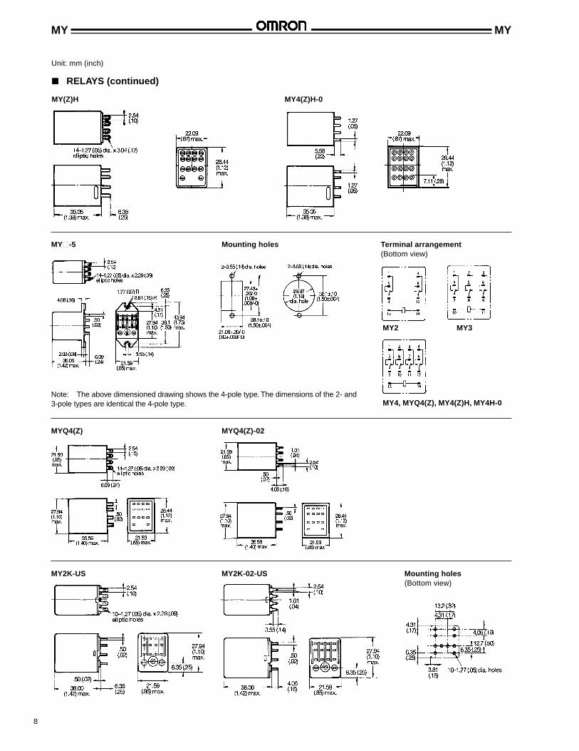
MY(Z)H MY4(Z)H-0
Unit: mm (inch)
RELAYS (continued)
MY-5 Mounting holes Terminal arrangement(Bottom view)
MY2 MY3
MY4, MYQ4(Z), MY4(Z)H, MY4H-0
MYQ4(Z) MYQ4(Z)-02
Note: The above dimensioned drawing shows the 4-pole type. The dimensions of the 2- and3-pole types are identical the 4-pole type.
MY2K-US MY2K-02-US Mounting holes(Bottom view)

9
MY MY
ACCESSORIES
Unit: mm (inch)
Track mounted sockets (UL File No. E87929) (CSA Report No. LR46088)
PYF08A-E Terminal arrangement/ PYF11A Terminal arrangement/mounting holes mounting holes(Top view) (Top view)
PYF14A-E Terminal arrangement/ Mounting height ofmounting holes relay with socket(Top view)
Note: 1. UL/CSA does not apply to wire wrap (Q) type sockets.2. Value in brackets is for MYCR.
Back connecting socket (UL File No. E87929) (CSA Report No. LR46088) – DPDT
PY08 PY08QN PY08-02
Back connecting socket (UL File No. E87929) (CSA Report No. LR46088) – 3PDT
PY11 PY11QN PY11-02

10
MY MY
ACCESSORIES (continued)
Unit: mm (inch)
Back connecting socket (UL File No. E87929) (CSA Report No. LR46088) – 4PDT
PY14 PY14QN PY14-02
Terminal arrangement (Bottom view) Panel cutout Mounting height ofrelay with socket
Mounting holes
DPDT 3PDT 4PDT
Relay hold-down clip
PYC-A1 PYC-P PYC-Sfor PYFA socket for PY socket for relay mounting plates
Note: Value in brackets is for MY-CR.
DPDT 3DPT 4DPT
* For types wiith suffix - 02.
11
MY MY
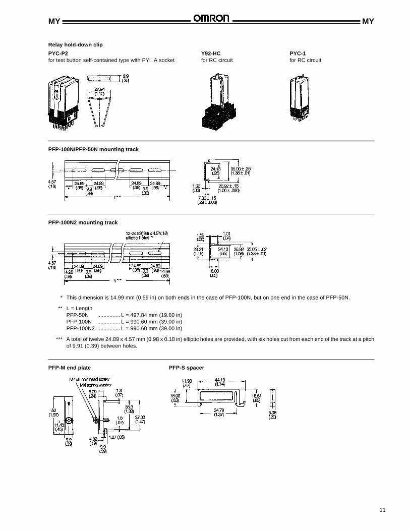
Relay hold-down clip
PYC-P2 Y92-HC PYC-1for test button self-contained type with PYA socket for RC circuit for RC circuit
PFP-100N/PFP-50N mounting track
PFP-100N2 mounting track
* This dimension is 14.99 mm (0.59 in) on both ends in the case of PFP-100N, but on one end in the case of PFP-50N.
** L = LengthPFP-50N ............... L = 497.84 mm (19.60 in)PFP-100N ............... L = 990.60 mm (39.00 in)PFP-100N2 ............... L = 990.60 mm (39.00 in)
*** A total of twelve 24.89 x 4.57 mm (0.98 x 0.18 in) elliptic holes are provided, with six holes cut from each end of the track at a pitchof 9.91 (0.39) between holes.
PFP-M end plate PFP-S spacer

12
MY MY
ACCESSORIES (continued)
Unit: mm (inch)
Socket mounting plates [t=1.52 (.06)]
PYP-1 PYP-18 PYP-36
Number of socket specs.
Socket needed 1 18 36
PY08, PY11, PY11QN, PYP-1 PYP-18 PYP-36PY14, PY4QN
RELAY OPTIONS
LED Indicator
Specifications and dimensions same as the standard typewith the following exception. Because an LED indicator isemployed as the operation indicator, the rated current isapproximately 3.8 mA higher in the DC types and 0.5 to 5 mAhigher in the AC types than in the standard type.
Ambient operating temperature: -55° to 60°C (-67° to 140°F).
Green LED ............ DCRed LED ............... AC
Terminal arrangement/Internal connections (Bottom view)
MY4N
DC coil rating type AC coil rating type
Note: 1. In MY2N and MY3N, only the contact circuit is different from the illustration below. The coil terminals 10 and 11 of MY3Nbecome (-) and (+), respectively.
2. Pay special attention to the polarities when using the DC type.3. The AC coil-type is provided with a self-diagnostic function that detects a breakage in the coil.
RC Circuit
Specifications and dimensions same as the standard type with thefollowing exceptions.
The panel cutout dimensions are the same as those of the standard type.However, the height is higher by 17.02 mm (0.67 in).
Note: 1. The above dimensioned drawing shows the 4-pole type. The dimensions of the 2- and 3-pole types are identical to the 4-pole type.
2. Available on AC versions only.3. Terminal arrangement/internal connections: MY2-Y is the same as the standard type; MY2N-Y is the same as the LED
indicator type.
Terminal arrangement/Internal connections(Bottom view)

13
MY MY
Note: 1. Pay special attention to the polarities when using the DC type.2. The release time is somewhat longer, but satisfies the standard specifications of 25 ms.3. The reverse-breakdown voltage of the diode is 1,000 VDC.4. Available on DC versions only.
Diode Surge Suppression
Specifications and dimensions same as the standardtype with the following exceptions.
Terminal arrangement/internal connections: MY2(N)-D(2) is the same as the MY4(N)-D(2) with the exceptionof the contact configuration.
Ambient operating temperature: -55° to 60°C (-67° to140°F).
Characteristic Data
Without RC circuit With RC circuit
Push-to-test button
MY12 Mounting holesWhen mounting the relay, use the connecting socket PYC-P2 shownin “ACCESSORIES” section. The mounting hole dimensions shownhere are applicable to the relay with mounting stud.
Note: The dimension drawings show the 4-pole type. The dimensions of the 2- and 3-pole types are identical to the 4-pole type.
Terminal arrangement/Internal connections (Bottom view)
MY4-D MY4N-D2 MY4N-D26, 12, 24, 48 6, 12, 24, 48 VDC 100/110 VDC100/110 VDC
Connecting sockets
Use the standard MY4 (4PDT) sockets with the terminal arrangements listed below.
Terminal arrangement/Internal connections (Bottom view)
AC DC
Note: 1. R is a resistor for ampere-turn compensation, and is incorporated in the relays rated at 50 VAC or above.2. Pay attention to the polarity of the set and reset coils, as incorrect connection of positive and negative terminals will result in
malfunctioning of the relay.

14
MY MY
Type Contact form Coil ratings Contact ratings
MY DPDT 6 to 240 VAC 5 A, 120 VAC (Resistive)
6 to 120 VDC 5 A, 28 VDC (Resistive)
5 A, 240 VAC (Inductive)
3PDT 5 A, 28 VDC (Resistive)
5 A, 240 VAC (Resistive)
4PDT 3 A, 28 VDC (Resistive)
3 A, 120 VAC (Inductive)
1.5 A, 240 VAC (Inductive)
5 A, 240 VAC (Inductive, same polarity)
5 A, 28 VDC (Resistive, same polarity)
MY2K- DPDT 5 to 120 VAC 3 A, 240 VAC (Resistive)
5 to 48 VDC 3 A, 28 VDC (Resistive)
APPROVALS
UL recognized type (File No. E41515)
Note: 1. The rated values approved by each of the safety standards (e.g., UL, CSA, VDE, and SEV) may be different from theperformance characteristics individually defined in this catalog.
2. In the interest of product improvement, specifications are subject to change.
Type Contact form Coil ratings Contact ratings
MY DPDT 6 to 240 VAC 5 A, 28 VDC (Resistive)
3PDT 6 to 120 VDC 5 A, 240 VAC (Inductive)
4PDT 3 A, 28 VDC (Resistive)
3 A, 240 VAC (Inductive)
5 A, 240 VAC (Inductive, same polarity)
5 A, 28 VDC (Resistive, same polarity)
MY2K- DPDT 5 to 120 VAC 3 A, 240 VAC (General purpose)
5 to 48 VDC 3 A, 30 VDC (Resistive)
CSA certified type (File No. LR31928)
Type Contact form Coil ratings Contact ratings
MY DPDT 6 to 240 VAC 2 A, 30 VDC (Inductive)
4PDT 6 to 120 VDC 2 A, 200 VAC (Inductive)
1.5 A, 30 VDC (Inductive)
0.8 A, 200 VAC (Inductive)
1.5 A, 115 VAC (Inductive)
LR (Lloyd's Register) approved type (File No. 563KOB-204524)
Type Contact form Coil ratings Contact ratings
MY-SV DPDT 6 to 240 VAC 5 A, 220 VAC (Resistive)
3PDT 6 to 110 VDC 5 A, 24 VDC (Resistive)
4PDT
SEV listed type (File No. D791/63 [2- & 4-pole], D791/91 [3-pole])
HINTS ON CORRECT USE
When using the relay rated at 120 VAC at a supply voltage of240 VAC, be sure to connect external resistors Rs and Rr tothe relay.

15
MY MY
OMRON ELECTRONICS, INC. OMRON CANADA, INC.One East Commerce Drive 885 Milner AvenueSchaumburg, IL 60173 Scarborough, Ontario M1B 5V81-800-55-OMRON 416-286-6465
Cat. No. GC RLY6 9/97 Specifications subject to change without notice. Printed in the U.S.A.

![[XLS] · Web viewSGR-12 RECLOSING RELAY TT-8 RELAY PERCENTAGE DIFFERENTIAL TRANSFORMER CVE SYNCRO VERIFIER RELAY HU-4 TRANSFORMER DIFFERENTIAL RELAY HCB RELAY TD-5 TIME DELAY RELAY](https://static.fdocuments.us/doc/165x107/5aebb2387f8b9a36698eaca3/xls-viewsgr-12-reclosing-relay-tt-8-relay-percentage-differential-transformer.jpg)