General Packet Radio Service (GPRS); Service description ... · PDF fileGeneral Packet Radio...
107
EN 301 344 V6.3.2 (1999-07) European Standard (Telecommunications series) Digital cellular telecommunications system (Phase 2+); General Packet Radio Service (GPRS); Service description; Stage 2 (GSM 03.60 version 6.3.2 Release 1997) GLOBAL SYSTEM FOR MOBILE COMMUNICATIONS R
Transcript of General Packet Radio Service (GPRS); Service description ... · PDF fileGeneral Packet Radio...
EN 301 344 V6.3.2 (1999-07)European Standard (Telecommunications series)
Digital cellular telecommunications system (Phase 2+);General Packet Radio Service (GPRS);
Service description;Stage 2
(GSM 03.60 version 6.3.2 Release 1997)
GLOBAL SYSTEM FOR MOBILE COMMUNICATIONS
R
ETSI
EN 301 344 V6.3.2 (1999-07)2GSM 03.60 version 6.3.2 Release 1997
ReferenceDEN/SMG-030360Q6 (cg00311c.PDF)
KeywordsDigital cellular telecommunications system,Global System for Mobile communications
(GSM), GPRS
ETSI
Postal addressF-06921 Sophia Antipolis Cedex - FRANCE
Office address650 Route des Lucioles - Sophia Antipolis
Valbonne - FRANCETel.: +33 4 92 94 42 00 Fax: +33 4 93 65 47 16
Siret N° 348 623 562 00017 - NAF 742 CAssociation à but non lucratif enregistrée à laSous-Préfecture de Grasse (06) N° 7803/88
Individual copies of this ETSI deliverablecan be downloaded from
http://www.etsi.orgIf you find errors in the present document, send your
comment to: [email protected]
Copyright Notification
No part may be reproduced except as authorized by written permission.The copyright and the foregoing restriction extend to reproduction in all media.
© European Telecommunications Standards Institute 1999.All rights reserved.
ETSI
EN 301 344 V6.3.2 (1999-07)3GSM 03.60 version 6.3.2 Release 1997
Contents
Intellectual Property Rights................................................................................................................................8
Foreword ............................................................................................................................................................8
1 Scope........................................................................................................................................................9
2 References................................................................................................................................................9
3 Definitions, abbreviations and symbols .................................................................................................113.1 Definitions ....................................................................................................................................................... 113.2 Abbreviations................................................................................................................................................... 113.3 Symbols ........................................................................................................................................................... 12
4 Main Concepts .......................................................................................................................................13
5 General GPRS Architecture and Transmission Mechanism..................................................................145.1 GPRS Access Interfaces and Reference Points................................................................................................ 145.2 Network Interworking...................................................................................................................................... 145.2.1 PSPDN Interworking.................................................................................................................................. 155.2.2 Internet (IP) Interworking .......................................................................................................................... 155.3 High-Level Functions Required for GPRS ...................................................................................................... 155.3.1 Network Access Control Functions............................................................................................................ 155.3.1.1 Registration Function............................................................................................................................ 165.3.1.2 Authentication and Authorisation Function .......................................................................................... 165.3.1.3 Admission Control Function................................................................................................................. 165.3.1.4 Message Screening Function ................................................................................................................ 165.3.1.5 Packet Terminal Adaptation Function .................................................................................................. 165.3.1.6 Charging Data Collection Function ...................................................................................................... 165.3.2 Packet Routeing and Transfer Functions.................................................................................................... 165.3.2.1 Relay Function...................................................................................................................................... 165.3.2.2 Routeing Function ................................................................................................................................ 165.3.2.3 Address Translation and Mapping Function......................................................................................... 175.3.2.4 Encapsulation Function ........................................................................................................................ 175.3.2.5 Tunnelling Function.............................................................................................................................. 175.3.2.6 Compression Function .......................................................................................................................... 175.3.2.7 Ciphering Function ............................................................................................................................... 175.3.2.8 Domain Name Server Function ............................................................................................................ 175.3.3 Mobility Management Functions................................................................................................................ 175.3.4 Logical Link Management Functions ......................................................................................................... 175.3.4.1 Logical Link Establishment Function ................................................................................................... 175.3.4.2 Logical Link Maintenance Functions.................................................................................................... 185.3.4.3 Logical Link Release Function ............................................................................................................. 185.3.5 Radio Resource Management Functions .................................................................................................... 185.3.5.1 Um Management Function ................................................................................................................... 185.3.5.2 Cell Selection Function......................................................................................................................... 185.3.5.3 Um-tranx Function................................................................................................................................ 185.3.5.4 Path Management Function .................................................................................................................. 185.3.6 Network Management Functions................................................................................................................ 185.4 Logical Architecture ........................................................................................................................................ 185.4.1 GPRS Support Nodes................................................................................................................................. 195.4.2 GPRS Backbone Networks ........................................................................................................................ 195.4.3 HLR............................................................................................................................................................ 205.4.4 SMS-GMSC and SMS-IWMSC................................................................................................................. 205.4.5 GPRS Mobile Stations ............................................................................................................................... 205.5 Assignment of Functions to General Logical Architecture .............................................................................. 215.6 Transmission and Signalling Planes................................................................................................................. 225.6.1 Transmission Plane .................................................................................................................................... 225.6.2 Signalling Plane.......................................................................................................................................... 235.6.2.1 MS - SGSN........................................................................................................................................... 23

ETSI
EN 301 344 V6.3.2 (1999-07)4GSM 03.60 version 6.3.2 Release 1997
5.6.2.2 SGSN - HLR......................................................................................................................................... 235.6.2.3 SGSN - MSC/VLR ............................................................................................................................... 245.6.2.4 SGSN - EIR .......................................................................................................................................... 245.6.2.5 SGSN - SMS-GMSC or SMS-IWMSC ................................................................................................ 245.6.2.6 GSN - GSN........................................................................................................................................... 255.6.2.7 GGSN - HLR........................................................................................................................................ 255.6.2.7.1 MAP-based GGSN - HLR Signalling ............................................................................................. 255.6.2.7.2 GTP and MAP-based GGSN - HLR Signalling .............................................................................. 26
6 Mobility Management Functionality .....................................................................................................266.1 Definition of Mobility Management States...................................................................................................... 266.1.1 IDLE (GPRS) State .................................................................................................................................... 266.1.2 STANDBY State........................................................................................................................................ 266.1.3 READY State ............................................................................................................................................. 276.2 IDLE / STANDBY / READY State Functionality........................................................................................... 286.2.1 State Transitions and Functions.................................................................................................................. 286.2.2 READY Timer Function ............................................................................................................................ 306.2.3 Periodic RA Update Timer Function.......................................................................................................... 306.2.4 Mobile Reachable Timer Function............................................................................................................. 306.3 Interactions Between SGSN and MSC/VLR.................................................................................................... 316.3.1 Administration of the SGSN - MSC/VLR Association .............................................................................. 316.3.2 Combined RA / LA Updating..................................................................................................................... 326.3.3 CS Paging................................................................................................................................................... 326.3.3.1 Paging Co-ordination............................................................................................................................ 336.3.4 Non-GPRS Alert ........................................................................................................................................ 346.3.5 MS Information Procedure......................................................................................................................... 346.3.6 MM Information Procedure ....................................................................................................................... 356.4 MM Procedures ............................................................................................................................................... 356.5 Attach Function................................................................................................................................................ 366.6 Detach Function............................................................................................................................................... 396.6.1 MS-Initiated Detach Procedure.................................................................................................................. 406.6.2 Network-Initiated Detach Procedure.......................................................................................................... 406.6.2.1 SGSN-Initiated Detach Procedure........................................................................................................ 406.6.2.2 HLR-Initiated Detach Procedure .......................................................................................................... 416.7 Purge Function................................................................................................................................................. 416.8 Security Function ............................................................................................................................................. 426.8.1 Authentication of Subscriber...................................................................................................................... 426.8.2 User Identity Confidentiality ...................................................................................................................... 436.8.2.1 P-TMSI Signature................................................................................................................................. 436.8.2.2 P-TMSI Reallocation Procedure........................................................................................................... 436.8.3 User Data and GMM/SM Signalling Confidentiality ................................................................................. 436.8.3.1 Scope of Ciphering ............................................................................................................................... 436.8.3.2 GPRS Ciphering Algorithm.................................................................................................................. 446.8.4 Identity Check Procedures.......................................................................................................................... 446.9 Location Management Function....................................................................................................................... 446.9.1 Location Management Procedures ............................................................................................................. 456.9.1.1 Cell Update Procedure.......................................................................................................................... 456.9.1.2 Routeing Area Update Procedure ......................................................................................................... 456.9.1.2.1 Intra SGSN Routeing Area Update ................................................................................................. 466.9.1.2.2 Inter SGSN Routeing Area Update ................................................................................................. 476.9.1.3 Combined RA / LA Update Procedure ................................................................................................. 496.9.1.3.1 Combined Intra SGSN RA / LA Update ......................................................................................... 496.9.1.3.2 Combined Inter SGSN RA / LA Update ......................................................................................... 516.9.1.4 Periodic RA and LA Updates ............................................................................................................... 546.10 Subscriber Management Function.................................................................................................................... 546.10.1 Subscriber Management Procedures .......................................................................................................... 546.10.1.1 Insert Subscriber Data Procedure ......................................................................................................... 546.10.1.2 Delete Subscriber Data Procedure........................................................................................................ 556.11 Classmark Handling......................................................................................................................................... 556.11.1 Radio Access Classmark ............................................................................................................................ 556.11.2 SGSN Classmark........................................................................................................................................ 56
ETSI
EN 301 344 V6.3.2 (1999-07)5GSM 03.60 version 6.3.2 Release 1997
7 Network Management Functionality......................................................................................................56
8 Radio Resource Functionality................................................................................................................568.1 Cell Selection and Reselection......................................................................................................................... 568.2 Discontinuous Reception ................................................................................................................................. 578.3 Radio Resource Management .......................................................................................................................... 578.3.1 Layer Functions.......................................................................................................................................... 578.3.2 Model of Operation.................................................................................................................................... 578.3.2.1 Dynamic Allocation of Radio Resources.............................................................................................. 578.4 Paging for GPRS Downlink Transfer............................................................................................................... 57
9 Packet Routeing and Transfer Functionality..........................................................................................589.1 Definition of Packet Data Protocol States........................................................................................................ 589.1.1 INACTIVE State........................................................................................................................................ 589.1.2 ACTIVE State ............................................................................................................................................ 599.2 PDP Context Activation, Modification, and Deactivation Functions............................................................... 599.2.1 Static and Dynamic PDP Addresses........................................................................................................... 609.2.2 Activation Procedures ................................................................................................................................ 609.2.2.1 PDP Context Activation Procedure ...................................................................................................... 609.2.2.2 Network-Requested PDP Context Activation Procedure......................................................................619.2.2.2.1 Successful Network-Requested PDP Context Activation Procedure .............................................. 629.2.2.2.2 Unsuccessful Network-Requested PDP Context Activation Procedure .......................................... 639.2.2.3 Anonymous Access PDP Context Activation Procedure ...................................................................... 649.2.3 Modification Procedures ............................................................................................................................ 669.2.3.1 PDP Context Modification Procedure .................................................................................................. 669.2.4 Deactivation Procedures............................................................................................................................. 679.2.4.1 PDP Context Deactivation Initiated by MS Procedure......................................................................... 679.2.4.2 PDP Context Deactivation Initiated by SGSN Procedure..................................................................... 679.2.4.3 PDP Context Deactivation Initiated by GGSN Procedure....................................................................689.2.4.4 Anonymous Access PDP Context Deactivation Initiated by MS Procedure......................................... 689.2.4.5 Anonymous Access PDP Context Deactivation Initiated by GGSN Procedure.................................... 689.3 Packet Routeing and Transfer Function........................................................................................................... 699.4 Relay Function................................................................................................................................................. 709.5 Packet Terminal Adaptation Function ............................................................................................................. 709.6 Encapsulation Function.................................................................................................................................... 709.6.1 Encapsulation Between SGSN and GGSN................................................................................................. 709.6.2 Encapsulation Between SGSN and MS...................................................................................................... 70
10 Message Screening Functionality ..........................................................................................................71
11 Compatibility Issues...............................................................................................................................71
12 Transmission ..........................................................................................................................................7112.1 Transmission Modes ........................................................................................................................................ 7112.1.1 GTP Transmission Modes.......................................................................................................................... 7112.1.2 LLC Transmission Modes .......................................................................................................................... 7112.1.3 RLC Transmission Modes.......................................................................................................................... 7212.2 Logical Link Control Functionality.................................................................................................................. 7212.2.1 Addressing.................................................................................................................................................. 7212.2.2 Services ...................................................................................................................................................... 7212.2.3 Functions.................................................................................................................................................... 7212.3 Subnetwork Dependent Convergence Functionality ........................................................................................ 7312.3.1 Services ...................................................................................................................................................... 7312.3.2 Subfunctions............................................................................................................................................... 7412.4 Gb Interface ..................................................................................................................................................... 7412.4.1 Physical Layer Protocol ............................................................................................................................. 7412.4.2 Link Layer Protocols.................................................................................................................................. 7512.4.3 BSS GPRS Protocol ................................................................................................................................... 7512.4.3.1 Inter-dependency of the BSSGP and LLC Functions ........................................................................... 7512.4.3.2 BSSGP Addressing............................................................................................................................... 7612.4.3.3 BVCI Contexts in BSS and in SGSN ................................................................................................... 7612.4.3.4 Flow Control Between SGSN and BSS over the Gb Interface ............................................................. 76
ETSI
EN 301 344 V6.3.2 (1999-07)6GSM 03.60 version 6.3.2 Release 1997
12.5 Abis Interface................................................................................................................................................... 7712.5.1 Remote Packet Control Unit....................................................................................................................... 78
13 Information Storage ...............................................................................................................................7813.1 HLR ................................................................................................................................................................. 7813.2 SGSN............................................................................................................................................................... 8013.3 GGSN .............................................................................................................................................................. 8113.4 MS ................................................................................................................................................................... 8213.5 MSC/VLR........................................................................................................................................................ 8313.6 Recovery and Restoration Procedures ............................................................................................................. 8313.6.1 HLR Failure ............................................................................................................................................... 8313.6.2 SGSN Failure ............................................................................................................................................. 8413.6.3 GGSN Failure............................................................................................................................................. 8413.6.4 VLR Failure ............................................................................................................................................... 84
14 Identities.................................................................................................................................................8414.1 IMSI................................................................................................................................................................. 8414.2 Packet TMSI .................................................................................................................................................... 8514.3 NSAPI and TLLI ............................................................................................................................................. 8514.4 PDP Address.................................................................................................................................................... 8614.5 TID .................................................................................................................................................................. 8614.6 Routeing Area Identity..................................................................................................................................... 8614.7 Cell Identity ..................................................................................................................................................... 8614.8 GSN Addresses................................................................................................................................................ 8714.8.1 GSN Address.............................................................................................................................................. 8714.8.2 GSN Number.............................................................................................................................................. 8714.9 Access Point Name .......................................................................................................................................... 87
15 Operational Aspects ...............................................................................................................................8715.1 Charging .......................................................................................................................................................... 8715.1.1 Charging Information ................................................................................................................................. 8715.1.2 Reverse Charging ....................................................................................................................................... 8815.2 Quality of Service Profile ................................................................................................................................ 8815.2.1 Precedence Class........................................................................................................................................ 8915.2.2 Delay Class................................................................................................................................................. 8915.2.3 Reliability Class ......................................................................................................................................... 8915.2.4 Throughput Classes .................................................................................................................................... 9015.2.4.1 Peak Throughput Class......................................................................................................................... 9015.2.4.2 Mean Throughput Class........................................................................................................................ 90
16 Interactions with Other GSM Services ..................................................................................................9116.1 Point-to-point Short Message Service.............................................................................................................. 9116.1.1 Mobile-terminated SMS Transfer............................................................................................................... 9216.1.1.1 Unsuccessful Mobile-terminated SMS Transfer ................................................................................... 9216.1.2 Mobile-originated SMS Transfer ............................................................................................................... 9416.2 Circuit-switched Services................................................................................................................................. 9416.3 Supplementary Services................................................................................................................................... 95
ETSI
EN 301 344 V6.3.2 (1999-07)7GSM 03.60 version 6.3.2 Release 1997
Annex A (normative): GGSN Selection Decision Tree .....................................................................96
A.1 Definitions..............................................................................................................................................96
A.2 APN (R) .................................................................................................................................................96
A.3 APN Selection Rules..............................................................................................................................96
Annex B (informative): Data Transmission Routeing Examples.....................................................100
B.1 Data Routeing for an MS in its Home PLMN to and from an External PDN .....................................100
B.2 Data Routeing for a Roaming MS to and from an External PDN........................................................101
B.3 MS-to-MS Data Routeing via the Same GGSN...................................................................................101
B.4 MS-to-MS Data Routeing via Different GGSNs .................................................................................102
Annex C (informative): Figures ..........................................................................................................103
Annex D (informative): Tables............................................................................................................105
Annex E (informative): Document history.........................................................................................106
History............................................................................................................................................................107
ETSI
EN 301 344 V6.3.2 (1999-07)8GSM 03.60 version 6.3.2 Release 1997
Intellectual Property RightsIPRs essential or potentially essential to the present document may have been declared to ETSI. The informationpertaining to these essential IPRs, if any, is publicly available for ETSI members and non-members, and can be foundin SR 000 314: "Intellectual Property Rights (IPRs); Essential, or potentially Essential, IPRs notified to ETSI in respectof ETSI standards", which is available free of charge from the ETSI Secretariat. Latest updates are available on theETSI Web server (http://www.etsi.org/ipr).
Pursuant to the ETSI IPR Policy, no investigation, including IPR searches, has been carried out by ETSI. No guaranteecan be given as to the existence of other IPRs not referenced in SR 000 314 (or the updates on the ETSI Web server)which are, or may be, or may become, essential to the present document.
ForewordThis European Standard (Telecommunications series) has been produced by the Special Mobile Group (SMG).
The present document defines the stage-2 service description for a General Packet Radio Service (GPRS) within thedigital cellular telecommunications system (Phase 2+).
The contents of the present document are subject to continuing work within SMG and may change following formalSMG approval. Should SMG modify the contents of the present document it will then be re-submitted for OAP with anidentifying change of release date and an increase in version number as follows:
Version 6.x.y
where:
6 indicates GSM Release 1997 of Phase 2+
x the second digit is incremented for changes of substance, i.e. technical enhancements, corrections, updates,etc.
y the third digit is incremented when editorial only changes have been incorporated in the specification.
Proposed national transposition dates
Date of adoption of this EN: 18 June 1999
Date of latest announcement of this EN (doa): 30 September 1999
Date of latest publication of new National Standardor endorsement of this EN (dop/e): 31 March 2000
Date of withdrawal of any conflicting National Standard (dow): 31 March 2000
ETSI
EN 301 344 V6.3.2 (1999-07)9GSM 03.60 version 6.3.2 Release 1997
1 ScopeThe present document defines the stage-2 service description for a General Packet Radio Service (GPRS) on GSM.CCITT I.130 [29] describes a three-stage method for characterisation of telecommunication services, and CCITTQ.65 [31] defines stage 2 of the method.
This version of the stage-2 service description covers the first phase of GPRS, and does not meet all the services andfunctionality described in GSM 02.60 [3]. An update to the present document to meet all the services and functionalityin GSM 02.60 is foreseen.
The present document does not cover the lower layers of the GPRS GSM radio interface. GSM 03.64 [11] contains anoverall description of the radio interface.
The present document does not cover the GPRS point-to-multipoint services. GSM 03.61 [9] contains the PTMmulticast stage-2 service description. GSM 03.62 [10] contains the PTM group call stage-2 service description.
2 ReferencesThe following documents contain provisions which, through reference in this text, constitute provisions of the presentdocument.
• References are either specific (identified by date of publication, edition number, version number, etc.) ornon-specific.
• For a specific reference, subsequent revisions do not apply.
• For a non-specific reference, the latest version applies.
• A non-specific reference to an ETS shall also be taken to refer to later versions published as an EN with the samenumber.
[1] GSM 01.04: "Digital cellular telecommunications system (Phase 2+); Abbreviations andacronyms".
[2] GSM 01.61: "Digital cellular telecommunications system (Phase 2+); GPRS ciphering algorithmrequirements".
[3] GSM 02.60: "Digital cellular telecommunications system (Phase 2+); General Packet RadioService (GPRS); Service description; Stage 1".
[4] GSM 03.03: "Digital cellular telecommunications system (Phase 2+); Numbering, addressing andidentification".
[5] GSM 03.07: "Digital cellular telecommunications system (Phase 2+); Restoration procedures".
[6] GSM 03.20: "Digital cellular telecommunications system (Phase 2+); Security related networkfunctions".
[7] GSM 03.22: "Digital cellular telecommunications system (Phase 2+); Functions related to MobileStation (MS) in idle mode and group receive mode".
[8] GSM 03.40: "Digital cellular telecommunications system (Phase 2+); Technical realization of theShort Message Service (SMS); Point-to-Point (PP)".
[9] GSM 03.61: "Digital cellular telecommunications system (Phase 2+); General Packet RadioService (GPRS); Point to Multipoint Multicast Service Description; Stage 2".
[10] GSM 03.62: "Digital cellular telecommunications system (Phase 2+); General Packet RadioService (GPRS); Point to Multipoint Group Call Service Description; Stage 2".
[11] GSM 03.64: "Digital cellular telecommunications system (Phase 2+); Overall description of theGeneral Packet Radio Service (GPRS) Radio interface; Stage 2".
ETSI
EN 301 344 V6.3.2 (1999-07)10GSM 03.60 version 6.3.2 Release 1997
[12] GSM 04.07: "Digital cellular telecommunications system (Phase 2+); Mobile radio interfacesignalling layer 3; General aspects".
[13] GSM 04.08: "Digital cellular telecommunications system (Phase 2+); Mobile radio interface layer3 specification".
[14] GSM 04.60: "Digital cellular telecommunications system (Phase 2+); General Packet RadioService (GPRS); Mobile Station (MS) - Base Station System (BSS) interface; Radio Link Control /Medium Access Control (RLC/MAC) protocol".
[15] GSM 04.64: "Digital cellular telecommunications system (Phase 2+); General Packet RadioService (GPRS); Logical Link Control (LLC)".
[16] GSM 04.65: "Digital cellular telecommunications system (Phase 2+); General Packet RadioService (GPRS); Subnetwork Dependent Convergence Protocol (SNDCP)".
[17] GSM 07.60: "Digital cellular telecommunications system (Phase 2+); General Packet RadioService (GPRS); Mobile Station (MS) supporting GPRS".
[18] GSM 08.08: "Digital cellular telecommunications system (Phase 2+); Mobile Switching Centre -Base Station System (MSC - BSS) interface: Layer 3 specification".
[19] GSM 08.14: "Digital cellular telecommunications system (Phase 2+); General Packet RadioService (GPRS); Base Station System (BSS) - Serving GPRS Support Node (SGSN) interface; Gbinterface layer 1".
[20] GSM 08.16: "Digital cellular telecommunications system (Phase 2+); General Packet RadioService (GPRS); Base Station System (BSS) - Serving GPRS Support Node (SGSN) interface;Network Service".
[21] GSM 08.18: "Digital cellular telecommunications system (Phase 2+); General Packet RadioService (GPRS); Base Station System (BSS) - Serving GPRS Support Node (SGSN); BSS GPRSProtocol (BSSGP)".
[22] GSM 08.60: "Digital cellular telecommunications system (Phase 2+); Inband control of remotetranscoders and rate adaptors for Enhanced Full Rate (EFR) and full rate traffic channels."
[23] GSM 09.02: "Digital cellular telecommunications system (Phase 2+); Mobile Application Part(MAP) specification".
[24] GSM 09.16: "Digital cellular telecommunications system (Phase 2+); General Packet RadioService (GPRS); Serving GPRS Support Node (SGSN) - Visitors Location Register (VLR); Gsinterface network service specification".
[25] GSM 09.18: "Digital cellular telecommunications system (Phase 2+); General Packet RadioService (GPRS); Serving GPRS Support Node (SGSN) - Visitors Location Register (VLR); Gsinterface layer 3 specification".
[26] GSM 09.60: "Digital cellular telecommunications system (Phase 2+); General Packet RadioService (GPRS); GPRS Tunnelling Protocol (GTP) across the Gn and Gp Interface".
[27] GSM 09.61: "Digital cellular telecommunications system (Phase 2+); General requirements oninterworking between the Public Land Mobile Network (PLMN) supporting General Packet RadioService (GPRS) and Packet Data Networks (PDN)".
[28] GSM 11.11: "Digital cellular telecommunications system (Phase 2+); Specification of theSubscriber Identity Module - Mobile Equipment (SIM - ME) interface".
[29] CCITT Recommendations I.130: "General modelling methods – Method for the characterisation oftelecommunication services supported by an ISDN and network capabilities of an ISDN".
[30] CCITT Recommendation E.164: "Numbering plan for the ISDN era".
[31] CCITT Recommendation Q.65: "Methodology – Stage 2 of the method for the characterization ofservices supported by an ISDN".
ETSI
EN 301 344 V6.3.2 (1999-07)11GSM 03.60 version 6.3.2 Release 1997
[32] CCITT Recommendation V.42 bis: "Data communication over the telephone network – Datacompression procedures for data circuit-terminating equipment (DCE) using error correctionprocedures".
[33] CCITT Recommendation X.3: "Packet assembly disassembly facility (PAD) in a public datanetwork".
[34] CCITT Recommendation X.25: "Interface between data terminal equipment (DTE) and datacircuit-terminating equipment (DCE) for terminals operating in the packet mode and connected topublic data networks by dedicated circuit".
[35] CCITT Recommendation X.28: "DTE / DCE interface for a start-stop mode data terminalequipment accessing the packet assembly / disassembly facility (PAD) in a public data networksituated in the same country".
[36] CCITT Recommendation X.29: "Procedures for the exchange of control information and user databetween a packet assembly / disassembly (PAD) facility and a packet mode DTE or another PAD".
[37] CCITT Recommendation X.75: "Packet-switched signalling system between public networksproviding data transmission services".
[38] CCITT Recommendation X.121: "International Numbering Plan for Public Data Networks".
[39] IETF RFC 768 (1980): "User Datagram Protocol" (STD 6).
[40] IETF RFC 791 (1981): "Internet Protocol" (STD 5).
[41] IETF RFC 792 (1981): "Internet Control Message Protocol" (STD 5).
[42] IETF RFC 793 (1981): "Transmission Control Protocol" (STD 7).
[43] IETF RFC 1034 (1987): "Domain Names – Concepts and Facilities" (STD 7).
3 Definitions, abbreviations and symbols
3.1 DefinitionsRefer to GSM 02.60.
3.2 AbbreviationsFor the purposes of the present document the following abbreviations apply. Additional applicable abbreviations can befound in GSM 01.04 [1].
AA Anonymous AccessAPN Access Point NameATM Asynchronous Transfer ModeBG Border GatewayBSSAP+ Base Station System Application Part +BSSGP Base Station System GPRS ProtocolBVCI BSSGP Virtual Connection IdentifierCCU Channel Codec UnitCGI Cell Global IdentificationCS Circuit SwitchedDNS Domain Name SystemGGSN Gateway GPRS Support NodeGMM/SM GPRS Mobility Management and Session ManagementGSN GPRS Support NodeGTP GPRS Tunnelling Protocol
ETSI
EN 301 344 V6.3.2 (1999-07)12GSM 03.60 version 6.3.2 Release 1997
ICMP Internet Control Message ProtocolIETF Internet Engineering Task ForceIP Internet ProtocolIPv4 Internet Protocol version 4IPv6 Internet Protocol version 6ISP Internet Service ProviderLL-PDU LLC PDULLC Logical Link ControlMAC Medium Access ControlMNRF Mobile station Not Reachable FlagMNRG Mobile station Not Reachable for GPRS flagMNRR Mobile station Not Reachable ReasonMTP2 Message Transfer Part layer 2MTP3 Message Transfer Part layer 3NGAF Non-GPRS Alert FlagNS Network ServiceNSAPI Network layer Service Access Point IdentifierNSS Network SubSystemP-TMSI Packet TMSIPCU Packet Control UnitPDCH Packet Data CHannelPDN Packet Data NetworkPDP Packet Data Protocol, e.g., IP or X.25 [34]PDU Protocol Data UnitPPF Paging Proceed FlagPTM Point To MultipointPTP Point To PointPVC Permanent Virtual CircuitRA Routeing AreaRAC Routeing Area CodeRAI Routeing Area IdentityRLC Radio Link ControlSGSN Serving GPRS Support NodeSM Short MessageSM-SC Short Message service Service CentreSMS-GMSC Short Message Service Gateway MSCSMS-IWMSC Short Message Service Interworking MSCSN-PDU SNDCP PDUSNDC SubNetwork Dependent ConvergenceSNDCP SubNetwork Dependent Convergence ProtocolTCAP Transaction Capabilities Application PartTCP Transmission Control ProtocolTID Tunnel IdentifierTLLI Temporary Logical Link IdentityTRAU Transcoder and Rate Adaptor UnitUDP User Datagram Protocol
3.3 SymbolsFor the purposes of the present document the following symbols apply:
Gb Interface between an SGSN and a BSS.
Gc Interface between a GGSN and an HLR.
Gd Interface between a SMS-GMSC and an SGSN, and between a SMS-IWMSC and an SGSN.
Gf Interface between an SGSN and an EIR.
Gi Reference point between GPRS and an external packet data network.

ETSI
EN 301 344 V6.3.2 (1999-07)13GSM 03.60 version 6.3.2 Release 1997
Gn Interface between two GSNs within the same PLMN.
Gp Interface between two GSNs in different PLMNs. The Gp interface allows support of GPRSnetwork services across areas served by the co-operating GPRS PLMNs.
Gr Interface between an SGSN and an HLR.
Gs Interface between an SGSN and an MSC/VLR.
kbit/s Kilobits per second.
R Reference point between a non-ISDN compatible TE and MT. Typically this reference pointsupports a standard serial interface.
Um Interface between the mobile station (MS) and the GPRS fixed network part. The Um interface isthe GPRS network interface for providing packet data services over the radio to the MS. The MTpart of the MS is used to access the GPRS services through this interface.
4 Main ConceptsGPRS uses a packet-mode technique to transfer high-speed and low-speed data and signalling in an efficient manner.GPRS optimises the use of network and radio resources. Strict separation between the radio subsystem and networksubsystem is maintained, allowing the network subsystem to be reused with other radio access technologies. GPRS doesnot mandate changes to an installed MSC base.
New GPRS radio channels are defined, and the allocation of these channels is flexible: from 1 to 8 radio interfacetimeslots can be allocated per TDMA frame, timeslots are shared by the active users, and up and downlink are allocatedseparately. The radio interface resources can be shared dynamically between speech and data services as a function ofservice load and operator preference. Various radio channel coding schemes are specified to allow bitrates from 9 tomore than 150 kbit/s per user.
Applications based on standard data protocols are supported, and interworking is defined with IP networks and X.25networks. Specific point-to-point and point-to-multipoint services are supported for applications such as traffictelematics and UIC train control. GPRS allows SMS transfer over GPRS radio channels.
GPRS is designed to support from intermittent and bursty data transfers through to occasional transmission of largevolumes of data. Several quality of service profiles are supported. GPRS is designed for fast reservation to begintransmission of packets, typically 0,5 to 1 second. Charging should typically be based on the amount of data transferred.
Three GPRS MS modes of operation are supported: An MS in class-A mode of operation operates GPRS and otherGSM services simultaneously. An MS in class-B mode of operation monitors control channels for GPRS and other GSMservices simultaneously, but can only operate one set of services at one time. An MS in class-C mode of operationexclusively operates GPRS services.
GPRS introduces two new network nodes in the GSM PLMN: The Serving GPRS Support Node (SGSN), which is atthe same hierarchical level as the MSC, keeps track of the individual MSs' location and performs security functions andaccess control. The SGSN is connected to the base station system with Frame Relay. The Gateway GSN (GGSN)provides interworking with external packet-switched networks, and is connected with SGSNs via an IP-based GPRSbackbone network. The HLR is enhanced with GPRS subscriber information, and the SMS-GMSCs and SMS-IWMSCsare upgraded to support SMS transmission via the SGSN. Optionally, the MSC/VLR can be enhanced for more-efficientco-ordination of GPRS and non-GPRS services and functionality: e.g., paging for circuit-switched calls that can beperformed more efficiently via the SGSN, and combined GPRS and non-GPRS location updates.
GPRS security functionality is equivalent to the existing GSM security. The SGSN performs authentication and ciphersetting procedures based on the same algorithms, keys, and criteria as in existing GSM. GPRS uses a cipheringalgorithm optimised for packet data transmission. A GPRS ME can access the GPRS services with SIMs that are notGPRS-aware, and with GPRS-aware SIMs.
Cell selection may be performed autonomously by an MS, or the base station system instructs the MS to select a certaincell. The MS informs the network when it re-selects another cell or group of cells known as a routeing area.
ETSI
EN 301 344 V6.3.2 (1999-07)14GSM 03.60 version 6.3.2 Release 1997
In order to access the GPRS services, an MS shall first make its presence known to the network by performing a GPRSattach. This operation establishes a logical link between the MS and the SGSN, and makes the MS available for SMSover GPRS, paging via SGSN, and notification of incoming GPRS data.
In order to send and receive GPRS data, the MS shall activate the packet data address that it wants to use. This operationmakes the MS known in the corresponding GGSN, and interworking with external data networks can commence.
User data is transferred transparently between the MS and the external data networks with a method known asencapsulation and tunnelling: data packets are equipped with GPRS-specific protocol information and transferredbetween the MS and GGSN. This transparent transfer method lessens the requirement for the GPRS PLMN to interpretexternal data protocols, and it enables easy introduction of additional interworking protocols in the future. User data canbe compressed and protected with retransmission protocols for efficiency and reliability.
5 General GPRS Architecture and TransmissionMechanism
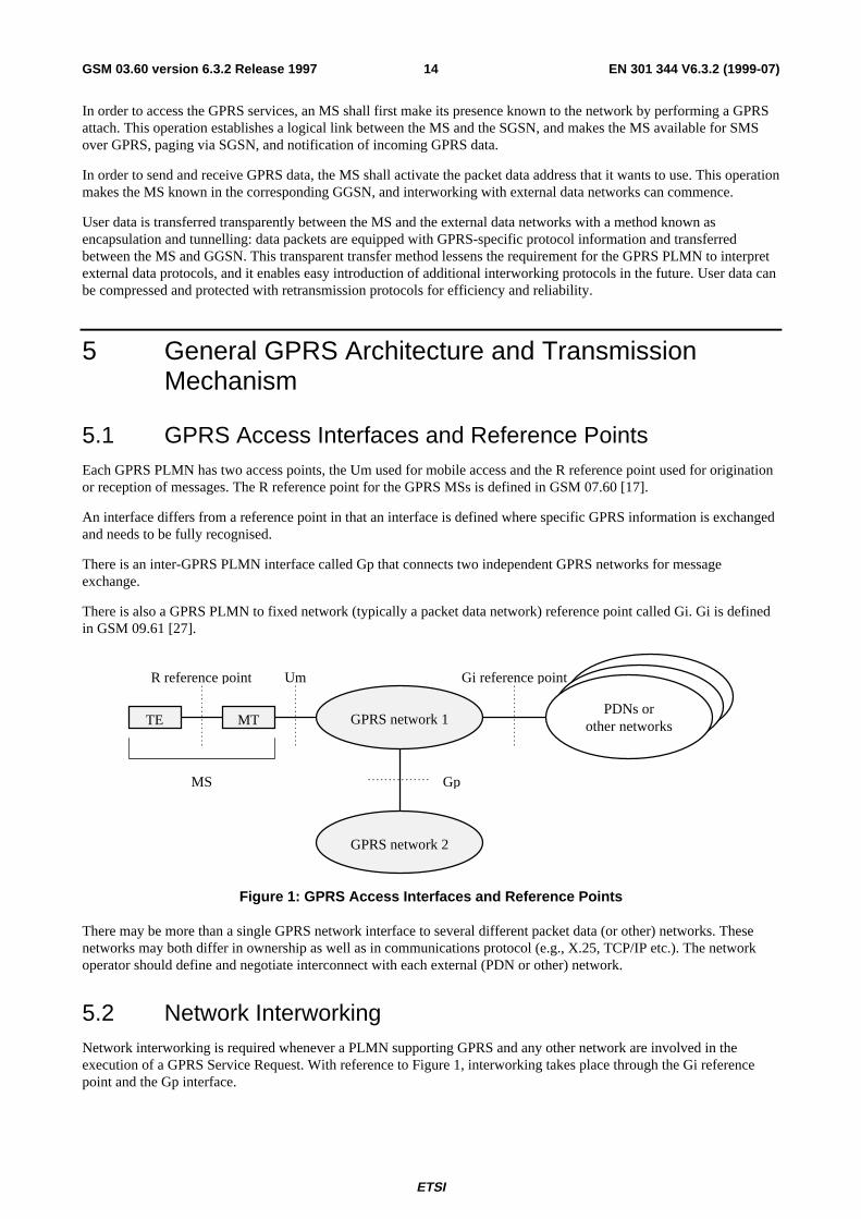
5.1 GPRS Access Interfaces and Reference PointsEach GPRS PLMN has two access points, the Um used for mobile access and the R reference point used for originationor reception of messages. The R reference point for the GPRS MSs is defined in GSM 07.60 [17].
An interface differs from a reference point in that an interface is defined where specific GPRS information is exchangedand needs to be fully recognised.
There is an inter-GPRS PLMN interface called Gp that connects two independent GPRS networks for messageexchange.
There is also a GPRS PLMN to fixed network (typically a packet data network) reference point called Gi. Gi is definedin GSM 09.61 [27].
Gi reference point
GPRS network 1
GPRS network 2
PDNs orother networksTE MT
Gp
UmR reference point
MS
Figure 1: GPRS Access Interfaces and Reference Points
There may be more than a single GPRS network interface to several different packet data (or other) networks. Thesenetworks may both differ in ownership as well as in communications protocol (e.g., X.25, TCP/IP etc.). The networkoperator should define and negotiate interconnect with each external (PDN or other) network.
5.2 Network InterworkingNetwork interworking is required whenever a PLMN supporting GPRS and any other network are involved in theexecution of a GPRS Service Request. With reference to Figure 1, interworking takes place through the Gi referencepoint and the Gp interface.

ETSI
EN 301 344 V6.3.2 (1999-07)15GSM 03.60 version 6.3.2 Release 1997
The GPRS internal mechanism for conveying the PDU through the GSM PLMN is managed by the GSM GPRS networkoperator and is not apparent to the data user. The use of this GSM data service may have an impact on and increase thetransfer time normally found for a message when communicated through a fixed packet data network.
5.2.1 PSPDN Interworking
GPRS shall support interworking with PSPDN networks. The interworking may be either direct or through a transitnetwork (e.g., ISDN). GPRS shall support both X.121 [38] and E.164 [30] addresses.
GPRS shall provide support for X.25 virtual circuits and X.25 fast select. X.75 [37] may be used for interworking withX.25 PDNs.
The GPRS TEs have addresses provided by the GSM PLMN GPRS service operator and belong to the GPRS servicedomain. The PSPDN TE sends data to the GPRS TE by use of the GSM PLMN GPRS DNIC (Data NetworkIdentification Code) or equivalent that uniquely identifies the GPRS network.
5.2.2 Internet (IP) Interworking
GPRS shall support interworking with networks based on the internet protocol (IP). IP is defined in RFC 791 [40].GPRS may provide compression of the TCP/IP header when an IP-datagram is used within the context of a TCPconnection.
In a similar way to the PSPDN X.25 case, the GSM PLMN GPRS service is an IP domain, and mobile terminals offeredservice by a GSM service provider may be globally addressable through the network operator's addressing scheme.
5.3 High-Level Functions Required for GPRSThe following list gives the logical functions performed within the GPRS network. Several functional groupings (meta-functions) are defined which each encompasses a number of individual functions:
- Network Access Control Functions.
- Packet Routeing and Transfer Functions.
- Mobility Management Functions.
- Logical Link Management Functions.
- Radio Resource Management Functions.
- Network Management Functions.
5.3.1 Network Access Control Functions
Network access is the means by which a user is connected to a telecommunication network in order to use the servicesand/or facilities of that network. An access protocol is a defined set of procedures that enables the user to employ theservices and/or facilities of the network.
User network access may occur from either the mobile side or the fixed side of the GPRS network. The fixed networkinterface may support multiple access protocols to external data networks, for example X.25 or IP. The set of accessprotocols to be supported is determined by the PLMN operator.
Individual PLMN administrations may require specific access-control procedures in order to limit the set of userspermitted to access the network, or to restrict the capabilities of individual users, for example by limiting the type ofservice available to an individual subscriber. Such access control procedures are beyond the scope of the GPRSspecifications.
ETSI
EN 301 344 V6.3.2 (1999-07)16GSM 03.60 version 6.3.2 Release 1997
In addition to the standard PTP data transfer, GPRS may support anonymous access to the network. The service allowsan MS to exchange data packets with a predefined host that can be addressed by the supported interworking protocols.Only a limited number of destination PDP addresses can be used within this service. IMSI or IMEI shall not be usedwhen accessing the network thus guaranteeing a high level of anonymity. Therefore, no authentication and cipheringfunctionalities are foreseen for anonymous access.
5.3.1.1 Registration Function
Registration is the means by which a user's Mobile Id is associated with the user's packet data protocol(s) andaddress(es) within the PLMN, and with the user's access point(s) to the external PDP network. The association can bestatic, i.e., stored in an HLR, or dynamic, i.e., allocated on a per need basis.
5.3.1.2 Authentication and Authorisation Function
This function performs the identification and authentication of the service requester, and the validation of the servicerequest type to ensure that the user is authorised to use the particular network services. The authentication function isperformed in association with the Mobility Management functions.
5.3.1.3 Admission Control Function
The purpose of admission control is to calculate which network resources are required to provide the quality of service(QoS) requested, determine if those resources are available, and then reserve those resources. Admission control isperformed in association with the Radio Resource Management functions in order to estimate the radio resourcerequirements within each cell.
5.3.1.4 Message Screening Function
A screening function concerned with filtering out unauthorised or unsolicited messages is required. This should besupported through packet filtering functions. Network-controlled screening is supported in the first phase of GPRS.Subscription-controlled and user-controlled screening may be provided in a later phase.
5.3.1.5 Packet Terminal Adaptation Function
This function adapts data packets received / transmitted from / to terminal equipment to a form suitable for transmissionacross the GPRS network.
5.3.1.6 Charging Data Collection Function
This function collects data necessary to support subscription and/or traffic fees.
5.3.2 Packet Routeing and Transfer Functions
A route is an ordered list of nodes used for the transfer of messages within and between the PLMN(s). Each routeconsists of the originating node, zero or more relay nodes and the destination node. Routeing is the process ofdetermining and using, in accordance with a set of rules, the route for transmission of a message within and between thePLMN(s).
5.3.2.1 Relay Function
The relay function is the means by which a node forwards data received from one node to the next node in the route.
5.3.2.2 Routeing Function
The routeing function determines the network node to which a message should be forwarded and the underlyingservice(s) used to reach that GPRS Support Node (GSN), using the destination address of the message. The routeingfunction selects the transmission path for the "next hop" in the route.
ETSI
EN 301 344 V6.3.2 (1999-07)17GSM 03.60 version 6.3.2 Release 1997
Data transmission between GSNs may occur across external data networks that provide their own internal routeingfunctions, for example X.25, Frame Relay or ATM networks.
5.3.2.3 Address Translation and Mapping Function
Address translation is the conversion of one address to another address of a different type. Address translation may beused to convert an external network protocol address into an internal network address that can be used for routeingpackets within and between the PLMN(s).
Address mapping is used to map a network address to another network address of the same type for the routeing andrelaying of messages within and between the PLMN(s), for example to forward packets from one network node toanother.
5.3.2.4 Encapsulation Function
Encapsulation is the addition of address and control information to a data unit for routeing packets within and betweenthe PLMN(s). Decapsulation is the removal of the addressing and control information from a packet to reveal theoriginal data unit.
Encapsulation and decapsulation are performed between the support nodes of the GPRS PLMN(s), and between theserving support node and the MS.
5.3.2.5 Tunnelling Function
Tunnelling is the transfer of encapsulated data units within and between the PLMN(s) from the point of encapsulation tothe point of decapsulation. A tunnel is a two-way point-to-point path. Only the tunnel endpoints are identified.
5.3.2.6 Compression Function
The compression function optimises use of radio path capacity by transmitting as little of the SDU (i.e., the exterior PDPPDU) as possible while at the same time as preserving the information contained within it.
5.3.2.7 Ciphering Function
The ciphering function preserves the confidentiality of user data and signalling across the radio channels and inherentlyprotects the PLMN from intruders.
5.3.2.8 Domain Name Server Function
The Domain Name Server function resolves logical GSN names to GSN addresses. This function is standard Internetfunctionality according to [43], which allows to resolve any name for GSNs and other GPRS nodes within the GPRSbackbone networks.
5.3.3 Mobility Management Functions
The mobility management functions are used to keep track of the current location of an MS within the PLMN or withinanother PLMN.
5.3.4 Logical Link Management Functions
Logical link management functions are concerned with the maintenance of a communication channel between anindividual MS and the PLMN across the radio interface. These functions involve the co-ordination of link stateinformation between the MS and the PLMN as well as the supervision of data transfer activity over the logical link.
Refer to GSM 04.64 [15] for further information.
5.3.4.1 Logical Link Establishment Function
Logical link establishment is performed when the MS attaches to the GPRS service.
ETSI
EN 301 344 V6.3.2 (1999-07)18GSM 03.60 version 6.3.2 Release 1997
5.3.4.2 Logical Link Maintenance Functions
Logical link maintenance functions supervise the logical link status and control link state changes.
5.3.4.3 Logical Link Release Function
The logical link release function is used to de-allocate resources associated with the logical link connection.
5.3.5 Radio Resource Management Functions
Radio resource management functions are concerned with the allocation and maintenance of radio communication paths.GSM radio resources is shared between the circuit mode (voice and data) services and the GPRS.
Refer to GSM 03.64 for further information.
5.3.5.1 Um Management Function
This function manages the set of physical channels used in each cell and determines the amount of radio resources to beallocated for GPRS use. The amount of radio resources allocated for GPRS may vary from cell to cell depending uponlocal user demand or other policies established by the PLMN operator.
5.3.5.2 Cell Selection Function
This function enables the MS to select the optimal cell for use in establishing a communication path with the PLMN.This involves the measurement and evaluation of signal quality from nearby cells as well as the detection and avoidanceof congestion within candidate cells.
Refer to GSM 03.22 [7] and GSM 03.64 for further information.
5.3.5.3 Um-tranx Function
The Um-tranx function provides packet data transfer capability across the radio interface between the MS and the BSS.This function includes procedures that:
- Provide medium access control over radio channels.
- Provide packet multiplexing over common physical radio channels.
- Provide packet discrimination within the MS.
- Provide error detection and correction.
- Provide flow control procedures.
5.3.5.4 Path Management Function
This function manages the packet data communication paths between the BSS and the serving GSN nodes. Theestablishment and release of these paths may be dynamic based upon the amount of data traffic or may be static basedupon the maximum expected load within each cell.
5.3.6 Network Management Functions
Network management functions provide mechanisms to support O&M functions related to GPRS.
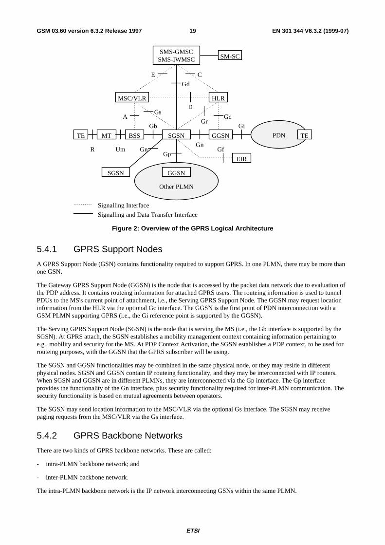
5.4 Logical ArchitectureGPRS is logically implemented on the GSM structure through the addition of two network nodes, the Serving GPRSSupport Node and the Gateway GPRS Support Node. It is necessary to name a number of new interfaces. No inferenceshould be drawn about the physical configuration on an interface from Figure 2.
ETSI
EN 301 344 V6.3.2 (1999-07)19GSM 03.60 version 6.3.2 Release 1997
Gf
D
Gi
Gn
Gb
Gc
CE
Gp
Gs
Signalling and Data Transfer Interface
Signalling Interface
MSC/VLR
TE MT BSS TEPDN
R Um
GrA
HLR
Other PLMN
SGSN
GGSN
Gd
SM-SCSMS-GMSCSMS-IWMSC
GGSN
EIR
SGSN
Gn
Figure 2: Overview of the GPRS Logical Architecture
5.4.1 GPRS Support Nodes
A GPRS Support Node (GSN) contains functionality required to support GPRS. In one PLMN, there may be more thanone GSN.
The Gateway GPRS Support Node (GGSN) is the node that is accessed by the packet data network due to evaluation ofthe PDP address. It contains routeing information for attached GPRS users. The routeing information is used to tunnelPDUs to the MS's current point of attachment, i.e., the Serving GPRS Support Node. The GGSN may request locationinformation from the HLR via the optional Gc interface. The GGSN is the first point of PDN interconnection with aGSM PLMN supporting GPRS (i.e., the Gi reference point is supported by the GGSN).
The Serving GPRS Support Node (SGSN) is the node that is serving the MS (i.e., the Gb interface is supported by theSGSN). At GPRS attach, the SGSN establishes a mobility management context containing information pertaining toe.g., mobility and security for the MS. At PDP Context Activation, the SGSN establishes a PDP context, to be used forrouteing purposes, with the GGSN that the GPRS subscriber will be using.
The SGSN and GGSN functionalities may be combined in the same physical node, or they may reside in differentphysical nodes. SGSN and GGSN contain IP routeing functionality, and they may be interconnected with IP routers.When SGSN and GGSN are in different PLMNs, they are interconnected via the Gp interface. The Gp interfaceprovides the functionality of the Gn interface, plus security functionality required for inter-PLMN communication. Thesecurity functionality is based on mutual agreements between operators.
The SGSN may send location information to the MSC/VLR via the optional Gs interface. The SGSN may receivepaging requests from the MSC/VLR via the Gs interface.
5.4.2 GPRS Backbone Networks
There are two kinds of GPRS backbone networks. These are called:
- intra-PLMN backbone network; and
- inter-PLMN backbone network.
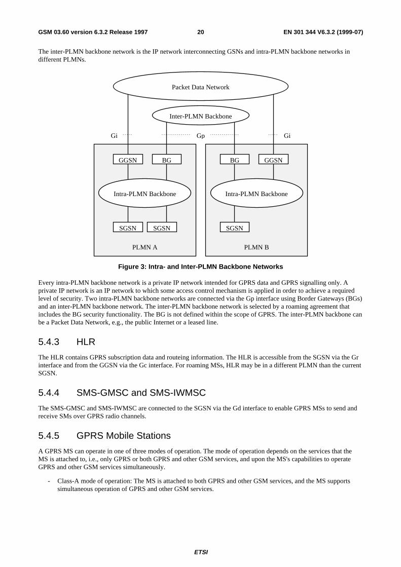
The intra-PLMN backbone network is the IP network interconnecting GSNs within the same PLMN.
ETSI
EN 301 344 V6.3.2 (1999-07)20GSM 03.60 version 6.3.2 Release 1997
The inter-PLMN backbone network is the IP network interconnecting GSNs and intra-PLMN backbone networks indifferent PLMNs.
BG
SGSN
BG
SGSN
GGSN GGSN
SGSN
Intra-PLMN BackboneIntra-PLMN Backbone
Gi Gp Gi
PLMN A PLMN B
Packet Data Network
Inter-PLMN Backbone
Figure 3: Intra- and Inter-PLMN Backbone Networks
Every intra-PLMN backbone network is a private IP network intended for GPRS data and GPRS signalling only. Aprivate IP network is an IP network to which some access control mechanism is applied in order to achieve a requiredlevel of security. Two intra-PLMN backbone networks are connected via the Gp interface using Border Gateways (BGs)and an inter-PLMN backbone network. The inter-PLMN backbone network is selected by a roaming agreement thatincludes the BG security functionality. The BG is not defined within the scope of GPRS. The inter-PLMN backbone canbe a Packet Data Network, e.g., the public Internet or a leased line.
5.4.3 HLR
The HLR contains GPRS subscription data and routeing information. The HLR is accessible from the SGSN via the Grinterface and from the GGSN via the Gc interface. For roaming MSs, HLR may be in a different PLMN than the currentSGSN.
5.4.4 SMS-GMSC and SMS-IWMSC
The SMS-GMSC and SMS-IWMSC are connected to the SGSN via the Gd interface to enable GPRS MSs to send andreceive SMs over GPRS radio channels.
5.4.5 GPRS Mobile Stations
A GPRS MS can operate in one of three modes of operation. The mode of operation depends on the services that theMS is attached to, i.e., only GPRS or both GPRS and other GSM services, and upon the MS's capabilities to operateGPRS and other GSM services simultaneously.
- Class-A mode of operation: The MS is attached to both GPRS and other GSM services, and the MS supportssimultaneous operation of GPRS and other GSM services.
ETSI
EN 301 344 V6.3.2 (1999-07)21GSM 03.60 version 6.3.2 Release 1997
- Class-B mode of operation: The MS is attached to both GPRS and other GSM services, but the MS can onlyoperate one set of services at a time. In network operation mode III (see subclause "Paging Co-ordination"), anMS that is capable of monitoring only one paging channel at a time cannot operate in class B mode of operation.In this case, such an MS shall revert to class-C mode of operation.
- Class-C mode of operation: The MS is exclusively attached to GPRS services.
NOTE: Other GSM technical specifications may refer to the MS modes of operation as GPRS class-A MS, GPRSclass-B MS, and GPRS class-C MS.
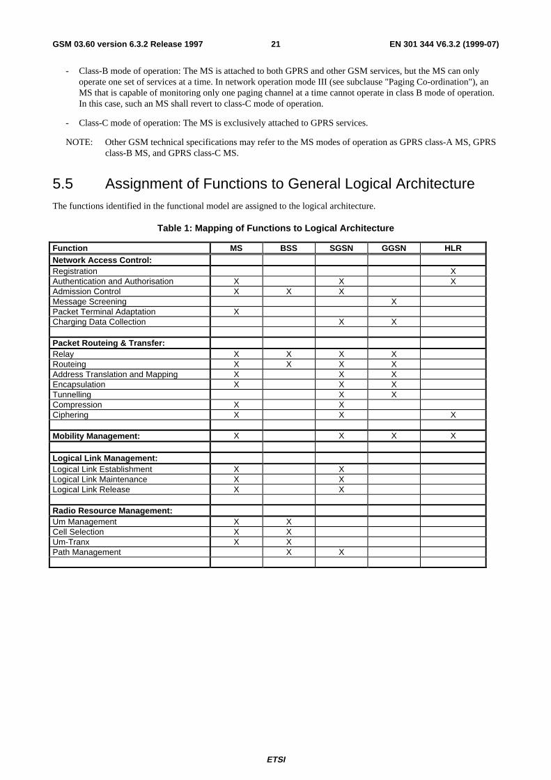
5.5 Assignment of Functions to General Logical ArchitectureThe functions identified in the functional model are assigned to the logical architecture.
Table 1: Mapping of Functions to Logical Architecture
Function MS BSS SGSN GGSN HLRNetwork Access Control:Registration XAuthentication and Authorisation X X XAdmission Control X X XMessage Screening XPacket Terminal Adaptation XCharging Data Collection X X
Packet Routeing & Transfer:Relay X X X XRouteing X X X XAddress Translation and Mapping X X XEncapsulation X X XTunnelling X XCompression X XCiphering X X X
Mobility Management: X X X X
Logical Link Management:Logical Link Establishment X XLogical Link Maintenance X XLogical Link Release X X
Radio Resource Management:Um Management X XCell Selection X XUm-Tranx X XPath Management X X
ETSI
EN 301 344 V6.3.2 (1999-07)22GSM 03.60 version 6.3.2 Release 1997
5.6 Transmission and Signalling Planes
5.6.1 Transmission Plane
The transmission plane consists of a layered protocol structure providing user information transfer, along withassociated information transfer control procedures (e.g., flow control, error detection, error correction and errorrecovery). The transmission plane independence of the Network Subsystem (NSS) platform from the underlying radiointerface is preserved via the Gb interface. The following transmission plane is used in GPRS:
Relay
NetworkService
GTP
Application
IP / X.25
SNDCP
LLC
RLC
MAC
GSM RF
SNDCP
LLC
BSSGP
L1bis
RLC
MAC
GSM RF
BSSGP
L1bis
Relay
L2
L1
IP
L2
L1
IP
GTP
IP / X.25
Um Gb Gn GiMS BSS SGSN GGSN
NetworkService
UDP /TCP
UDP /TCP
Figure 4: Transmission Plane
Legend:
- GPRS Tunnelling Protocol (GTP): This protocol tunnels user data and signalling between GPRS Support Nodesin the GPRS backbone network. All PTP PDP PDUs shall be encapsulated by the GPRS Tunnelling Protocol.GTP is specified in GSM 09.60 [26].
- TCP carries GTP PDUs in the GPRS backbone network for protocols that need a reliable data link (e.g., X.25),and UDP carries GTP PDUs for protocols that do not need a reliable data link (e.g., IP). TCP provides flowcontrol and protection against lost and corrupted GTP PDUs. UDP provides protection against corrupted GTPPDUs. TCP is defined in RFC 793 [42]. UDP is defined in RFC 768 [39].
- IP: This is the GPRS backbone network protocol used for routeing user data and control signalling. The GPRSbackbone network may initially be based on the IP version 4 protocol. Ultimately, IP version 6 shall be used. IPversion 4 is defined in RFC 791.
- Subnetwork Dependent Convergence Protocol (SNDCP): This transmission functionality maps network-levelcharacteristics onto the characteristics of the underlying network. SNDCP is specified in GSM 04.65 [16].
- Logical Link Control (LLC): This layer provides a highly reliable ciphered logical link. LLC shall beindependent of the underlying radio interface protocols in order to allow introduction of alternative GPRS radiosolutions with minimum changes to the NSS. LLC is specified in GSM 04.64.
- Relay: In the BSS, this function relays LLC PDUs between the Um and Gb interfaces. In the SGSN, this functionrelays PDP PDUs between the Gb and Gn interfaces.
- Base Station System GPRS Protocol (BSSGP): This layer conveys routeing- and QoS-related informationbetween BSS and SGSN. BSSGP does not perform error correction. BSSGP is specified in GSM 08.18 [21].
- Network Service (NS): This layer transports BSSGP PDUs. NS is based on the Frame Relay connection betweenBSS and SGSN, and may be multi-hop and traverse a network of Frame Relay switching nodes. NS is specifiedin GSM 08.16 [20].
- RLC/MAC: This layer contains two functions: The Radio Link Control function provides a radio-solution-dependent reliable link. The Medium Access Control function controls the access signalling (request and grant)procedures for the radio channel, and the mapping of LLC frames onto the GSM physical channel. RLC/MAC isdefined in GSM 04.60 [14].
ETSI
EN 301 344 V6.3.2 (1999-07)23GSM 03.60 version 6.3.2 Release 1997
- GSM RF: As defined in GSM 05 series.
5.6.2 Signalling Plane
The signalling plane consists of protocols for control and support of the transmission plane functions:
- controlling the GPRS network access connections, such as attaching to and detaching from the GPRS network;
- controlling the attributes of an established network access connection, such as activation of a PDP address;
- controlling the routeing path of an established network connection in order to support user mobility;
- controlling the assignment of network resources to meet changing user demands; and
- providing supplementary services.
The following signalling planes are used in GPRS:
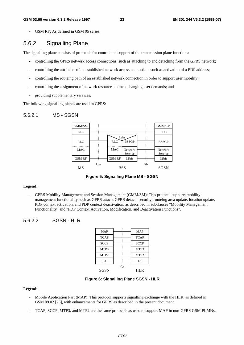
5.6.2.1 MS - SGSN
BSSGPRelay
GMM/SM
LLC
RLC
MAC
GSM RF
GMM/SM
LLC
BSSGP
L1bis
Um GbMS BSS SGSN
NetworkService
RLC
MAC
GSM RF L1bis
NetworkService
Figure 5: Signalling Plane MS - SGSN
Legend:
- GPRS Mobility Management and Session Management (GMM/SM): This protocol supports mobilitymanagement functionality such as GPRS attach, GPRS detach, security, routeing area update, location update,PDP context activation, and PDP context deactivation, as described in subclauses "Mobility ManagementFunctionality" and "PDP Context Activation, Modification, and Deactivation Functions".
5.6.2.2 SGSN - HLR
SCCP
MTP2
MTP3
MTP2
MTP3
SCCP
GrSGSN HLR
TCAP
MAP
TCAP
MAP
L1 L1
Figure 6: Signalling Plane SGSN - HLR
Legend:
- Mobile Application Part (MAP): This protocol supports signalling exchange with the HLR, as defined inGSM 09.02 [23], with enhancements for GPRS as described in the present document.
- TCAP, SCCP, MTP3, and MTP2 are the same protocols as used to support MAP in non-GPRS GSM PLMNs.
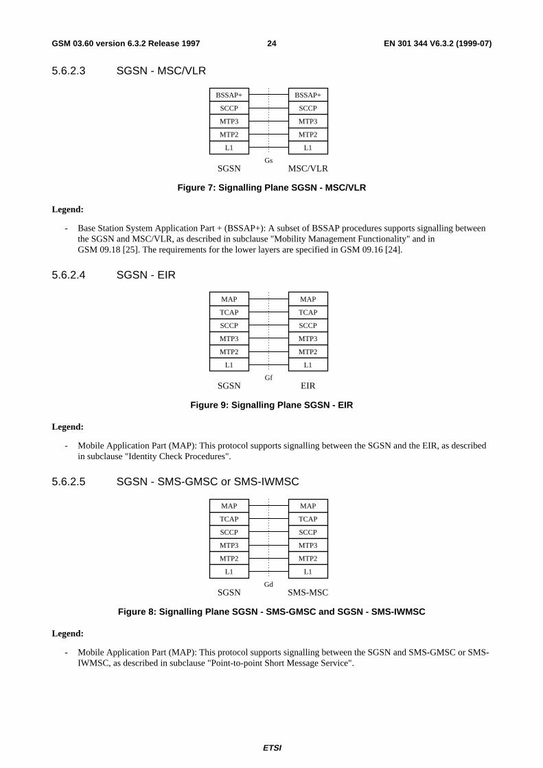
ETSI
EN 301 344 V6.3.2 (1999-07)24GSM 03.60 version 6.3.2 Release 1997
5.6.2.3 SGSN - MSC/VLR
SCCP
MTP2
MTP3
MTP2
MTP3
SCCP
GsSGSN MSC/VLR
BSSAP+ BSSAP+
L1 L1
Figure 7: Signalling Plane SGSN - MSC/VLR
Legend:
- Base Station System Application Part + (BSSAP+): A subset of BSSAP procedures supports signalling betweenthe SGSN and MSC/VLR, as described in subclause "Mobility Management Functionality" and inGSM 09.18 [25]. The requirements for the lower layers are specified in GSM 09.16 [24].
5.6.2.4 SGSN - EIR
SCCP
MTP2
MTP3
MTP2
MTP3
SCCP
GfSGSN EIR
TCAP
MAP
TCAP
MAP
L1 L1
Figure 9: Signalling Plane SGSN - EIR
Legend:
- Mobile Application Part (MAP): This protocol supports signalling between the SGSN and the EIR, as describedin subclause "Identity Check Procedures".
5.6.2.5 SGSN - SMS-GMSC or SMS-IWMSC
SCCP
MTP2
MTP3
MTP2
MTP3
SCCP
GdSGSN SMS-MSC
TCAP
MAP
TCAP
MAP
L1 L1
Figure 8: Signalling Plane SGSN - SMS-GMSC and SGSN - SMS-IWMSC
Legend:
- Mobile Application Part (MAP): This protocol supports signalling between the SGSN and SMS-GMSC or SMS-IWMSC, as described in subclause "Point-to-point Short Message Service".
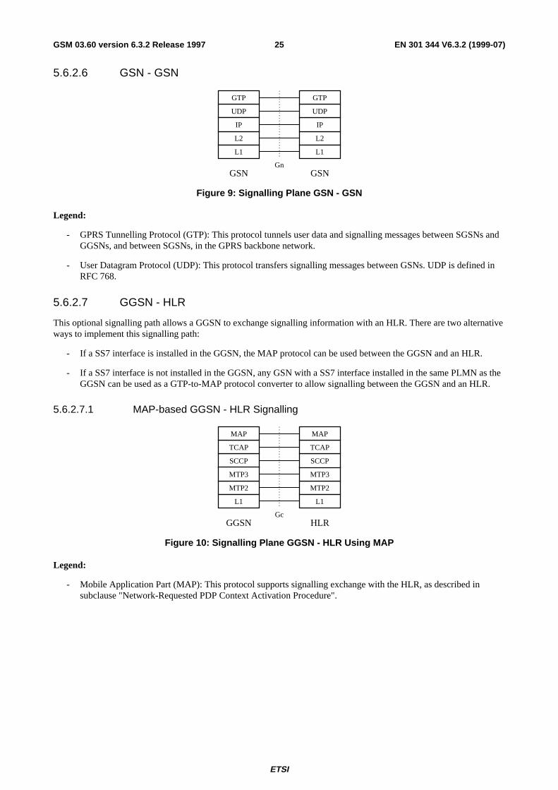
ETSI
EN 301 344 V6.3.2 (1999-07)25GSM 03.60 version 6.3.2 Release 1997
5.6.2.6 GSN - GSN
UDP
L2
L1
IP
L2
L1
IP
UDP
GnGSN GSN
GTP GTP
Figure 9: Signalling Plane GSN - GSN
Legend:
- GPRS Tunnelling Protocol (GTP): This protocol tunnels user data and signalling messages between SGSNs andGGSNs, and between SGSNs, in the GPRS backbone network.
- User Datagram Protocol (UDP): This protocol transfers signalling messages between GSNs. UDP is defined inRFC 768.
5.6.2.7 GGSN - HLR
This optional signalling path allows a GGSN to exchange signalling information with an HLR. There are two alternativeways to implement this signalling path:
- If a SS7 interface is installed in the GGSN, the MAP protocol can be used between the GGSN and an HLR.
- If a SS7 interface is not installed in the GGSN, any GSN with a SS7 interface installed in the same PLMN as theGGSN can be used as a GTP-to-MAP protocol converter to allow signalling between the GGSN and an HLR.
5.6.2.7.1 MAP-based GGSN - HLR Signalling
SCCP
MTP2
MTP3
MTP2
MTP3
SCCP
GcGGSN HLR
TCAP
MAP
TCAP
MAP
L1 L1
Figure 10: Signalling Plane GGSN - HLR Using MAP
Legend:
- Mobile Application Part (MAP): This protocol supports signalling exchange with the HLR, as described insubclause "Network-Requested PDP Context Activation Procedure".
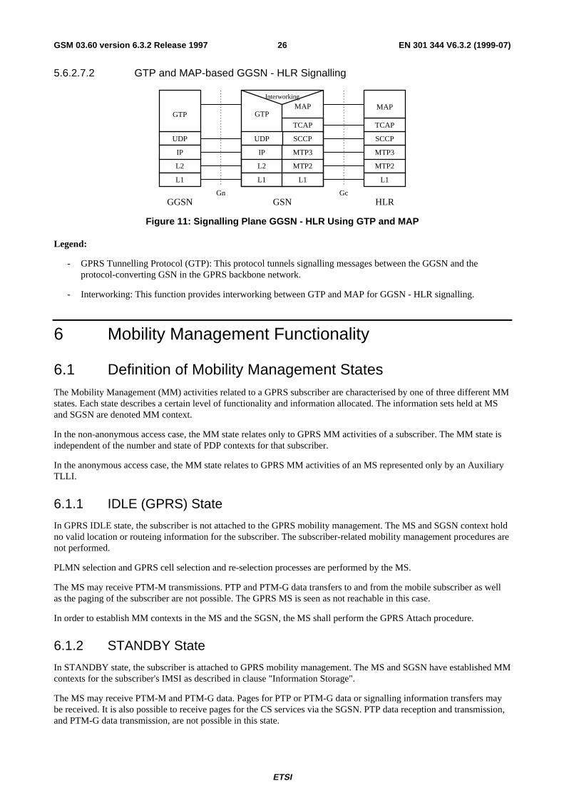
ETSI
EN 301 344 V6.3.2 (1999-07)26GSM 03.60 version 6.3.2 Release 1997
5.6.2.7.2 GTP and MAP-based GGSN - HLR Signalling
Gn
UDP
L2
IP
GGSN
L1
L2
IP
GSN
GTP
L1
MTP2
MTP3
SCCP
MAP
L1
MTP2
MTP3
SCCP
HLR
TCAP
MAP
L1
GTP
Gc
Interworking
TCAP
UDP
Figure 11: Signalling Plane GGSN - HLR Using GTP and MAP
Legend:
- GPRS Tunnelling Protocol (GTP): This protocol tunnels signalling messages between the GGSN and theprotocol-converting GSN in the GPRS backbone network.
- Interworking: This function provides interworking between GTP and MAP for GGSN - HLR signalling.
6 Mobility Management Functionality
6.1 Definition of Mobility Management StatesThe Mobility Management (MM) activities related to a GPRS subscriber are characterised by one of three different MMstates. Each state describes a certain level of functionality and information allocated. The information sets held at MSand SGSN are denoted MM context.
In the non-anonymous access case, the MM state relates only to GPRS MM activities of a subscriber. The MM state isindependent of the number and state of PDP contexts for that subscriber.
In the anonymous access case, the MM state relates to GPRS MM activities of an MS represented only by an AuxiliaryTLLI.
6.1.1 IDLE (GPRS) State
In GPRS IDLE state, the subscriber is not attached to the GPRS mobility management. The MS and SGSN context holdno valid location or routeing information for the subscriber. The subscriber-related mobility management procedures arenot performed.
PLMN selection and GPRS cell selection and re-selection processes are performed by the MS.
The MS may receive PTM-M transmissions. PTP and PTM-G data transfers to and from the mobile subscriber as wellas the paging of the subscriber are not possible. The GPRS MS is seen as not reachable in this case.
In order to establish MM contexts in the MS and the SGSN, the MS shall perform the GPRS Attach procedure.
6.1.2 STANDBY State
In STANDBY state, the subscriber is attached to GPRS mobility management. The MS and SGSN have established MMcontexts for the subscriber's IMSI as described in clause "Information Storage".
The MS may receive PTM-M and PTM-G data. Pages for PTP or PTM-G data or signalling information transfers maybe received. It is also possible to receive pages for the CS services via the SGSN. PTP data reception and transmission,and PTM-G data transmission, are not possible in this state.
ETSI
EN 301 344 V6.3.2 (1999-07)27GSM 03.60 version 6.3.2 Release 1997
The MS performs GPRS Routeing Area (RA) and GPRS cell selection and re-selection locally. The MS executesmobility management procedures to inform the SGSN when it has entered a new RA. The MS does not inform theSGSN on a change of cell in the same RA. Therefore, the location information in the SGSN MM context contains onlythe GPRS RAI for MSs in STANDBY state.
The MS may initiate activation or deactivation of PDP contexts while in STANDBY state. A PDP context shall beactivated before data can be transmitted or received for this PDP context.
The SGSN may have to send data or signalling information to an MS in STANDBY state. The SGSN then sends aPaging Request in the routeing area where the MS is located if PPF is set. If PPF is cleared, then paging is not done. TheMM state in the MS is changed to READY when the MS responds to the page, and in the SGSN when the page responseis received. Also, the MM state in the MS is changed to READY when data or signalling information is sent from theMS and, accordingly, the MM state in the SGSN is changed to READY when data or signalling information is receivedfrom the MS.
The MS or the network may initiate the GPRS Detach procedure to move to the IDLE state. After expiry of the mobilereachable timer the SGSN may perform an implicit detach in order to return the MM contexts in the SGSN to IDLEstate. The MM and PDP contexts may then be deleted.
6.1.3 READY State
In READY state, the SGSN MM context corresponds to the STANDBY MM context extended by location informationfor the subscriber on cell level. The MS performs mobility management procedures to provide the network with theactual selected cell. GPRS cell selection and re-selection is done locally by the MS, or may optionally be controlled bythe network.
An identifier of the cell, the Cell Global Identity including RAC and LAC, is included in the BSSGP header of the datapacket from the MS, see GSM 08.18.
The MS may send and receive PTP PDUs in this state. The network initiates no GPRS pages for an MS in READYstate, pages for other services may be done via the SGSN. The SGSN transfers downlink data to the BSS responsible forthe subscriber's actual GPRS cell.
The MS may receive PTM-M and PTM-G data in READY state.
The MS may activate or deactivate PDP contexts while in READY state.
Regardless if a radio resource is allocated to the subscriber or not, the MM context remains in the READY state evenwhen there is no data being communicated. The READY state is supervised by a timer. An MM context moves fromREADY state to STANDBY state when the READY timer expires. In order to move from READY state to IDLE state,the MS initiates the GPRS Detach procedure.
ETSI
EN 301 344 V6.3.2 (1999-07)28GSM 03.60 version 6.3.2 Release 1997
6.2 IDLE / STANDBY / READY State Functionality
6.2.1 State Transitions and Functions
The movement from one state to the next is dependent on the current state (IDLE, STANDBY, or READY) and theevent occurred (e.g., GPRS attach).
PDU transmission
Implicit Detachor
Cancel Location
GPRS Attach
READY timer expiryorForce to STANDBY
GPRS Detach GPRS Attach
PDU reception
GPRS Detachor
Cancel Location
MM State Model of MS MM State Model of SGSN
IDLE
READY
STANDBY
IDLE
READY
STANDBY
READY timer expiryorForce to STANDBYorAbnormal RLC condition
Figure 12: Functional Mobility Management State Model
Figure 12 describes the following state transitions:
Moving from IDLE to READY:
- GPRS Attach: The MS requests access and a logical link to an SGSN is initiated. MM contexts are established atthe MS and SGSN.
Moving from STANDBY to IDLE:
- Implicit Detach: The MM and PDP contexts in the SGSN shall return to IDLE and INACTIVE state. The MMand PDP contexts in the SGSN may be deleted. The GGSN PDP contexts shall be deleted.
- Cancel Location: The SGSN receives a MAP Cancel Location message from the HLR, and removes the MM andPDP contexts.
Moving from STANDBY to READY:
- PDU transmission: The MS sends an LLC PDU to the SGSN, possibly in response to a page.
- PDU reception: The SGSN receives an LLC PDU from the MS.
ETSI
EN 301 344 V6.3.2 (1999-07)29GSM 03.60 version 6.3.2 Release 1997
Moving from READY to STANDBY:
- READY timer expiry: The MS and the SGSN MM contexts return to STANDBY state.
- Force to STANDBY: The SGSN indicates an immediate return to STANDBY state before the READY timerexpires.
- Abnormal RLC condition: The SGSN MM context returns to STANDBY state in case of delivery problems onthe radio interface or in case of irrecoverable disruption of a radio transmission.
Moving from READY to IDLE:
- GPRS Detach: The MS or the network requests that the MM contexts to IDLE state and that the PDP contextsreturn to INACTIVE state. The SGSN may delete the MM and PDP contexts. The PDP contexts in the GGSNshall be deleted.
- Cancel Location: The SGSN receives a MAP Cancel Location message from the HLR, and removes the MM andPDP contexts.
For anonymous access, a reduced Mobility Management State Model consisting of IDLE and READY states is used.The AA MM state machine is independently handled by the MS and the network and may coexist with an IMSI-basedMM state machine. Several AA MM state machines may coexist in the same MS and SGSN simultaneously.
READY timer expiryor
AA PDP ContextDeactivation
AA PDP ContextActivation
AA MM State Model of MS
IDLE
READY
READY timer expiryor
Abnormal RLC conditionor
AA PDP ContextDeactivation
AA PDP ContextActivation
AA MM State Model of SGSN
IDLE
READY
Figure 13: Functional Anonymous Access Mobility Management State Model
Figure 13 describes the following state transitions for anonymous access:
Moving from IDLE to READY:
- AA PDP Context Activation: The MS requests an anonymous access and a logical link to an SGSN is initiated.MM contexts are established at the MS and SGSN, and PDP contexts are established at the MS, the SGSN, and aGGSN.
Moving from READY to IDLE:
- READY timer expiry: The MM and PDP contexts in the MS, the SGSN, and the GGSN are deleted.
- Abnormal RLC condition: The SGSN MM context shall be deleted in case of delivery problems on the radiointerface or in case of irrecoverable disruption of a radio transmission.
- AA PDP Context Deactivation: The network (either the SGSN or the GGSN) initiates the AA PDP ContextDeactivation procedure, e.g., due to malicious usage of the anonymous service. The MM and PDP contexts in theMS, the SGSN, and the GGSN shall be deleted.
ETSI
EN 301 344 V6.3.2 (1999-07)30GSM 03.60 version 6.3.2 Release 1997
6.2.2 READY Timer Function
The READY timer function maintains the READY timer in the MS and SGSN. The READY timer controls the time anMS remains in READY state in the MS and the SGSN. The READY timer shall be reset and begin running in the MSwhen an LLC PDU is transmitted, and in the SGSN when an LLC PDU is correctly received. When the READY timerexpires, the MS and SGSN MM contexts shall return to STANDBY state. In case of anonymous access the MM contextshall be deleted.
The length of the READY timer shall be the same in the MS and SGSN. The initial length of the READY timer shall bedefined by a default value. The SGSN, and only the SGSN, may change the length of the READY timer by transmittinga new value in the Attach Accept, Routeing Area Update Accept, or AA PDP Context Accept messages.
If the READY timer length is set to zero, the MS shall immediately be forced into STANDBY state. If the timer lengthis set to all 1s (binary), then the READY timer function shall be deactivated, i.e., the timer no longer runs and the MSremains in READY state.
6.2.3 Periodic RA Update Timer Function
The Periodic RA Update Timer function monitors the periodic RA update procedure in the MS. The length of theperiodic RA update timer is sent in the Routeing Area Update Accept or Attach Accept message. The periodic RAupdate timer is unique within an RA. Upon expiry of the periodic RA update timer, the MS shall start a periodicrouteing area update procedure.
If the MS is in coverage but out of GPRS coverage when the periodic RA update timer expires, then, if the MS is IMSI-attached to a network in network operation mode I, the periodic location update procedure (or other appropriate locationupdate procedure) shall be started immediately. In addition, and irrespective of whether or not the MS was IMSI-attached, regardless of the network operation mode, the periodic RA update procedure (or other appropriate updateprocedure) shall be started as soon as the MS returns to GPRS coverage.
If the MS is out of coverage when the periodic RA update timer expires then:
- if the MS is both IMSI and GPRS-attached and returns to coverage in a cell that supports GPRS in networkoperation mode I, then the combined RA / LA update procedure with IMSI attach requested shall be started assoon as the MS returns to coverage;
- if the MS is both IMSI and GPRS-attached and returns to coverage in a cell that supports GPRS in networkoperation mode II or III, or if a GPRS only-attached MS returns to coverage in a cell that supports GPRS, thenthe periodic RA update procedure shall be started as soon as the MS returns to coverage; or
- if the MS returns to coverage in a cell that does not support GPRS, and if the MS is IMSI-attached, then theperiodic location update procedure (or other appropriate location update procedure) shall be started as soon asthe MS returns to coverage in that cell. In addition, and irrespective of whether or not the MS was IMSI-attached,the periodic RA update procedure (or other appropriate update procedure) shall be started as soon as the MSreturns to GPRS coverage.
If the MS lost GPRS coverage but the periodic RA update timer did not expire while out of GPRS coverage, then, theMS shall not perform the periodic RA update procedure because of the MS's return to GPRS coverage.
If the MS lost coverage but the periodic RA update timer did not expire while out of coverage, then the MS shall notperform the periodic RA update procedure because of the MS's return to coverage.
6.2.4 Mobile Reachable Timer Function
The Mobile Reachable Timer function monitors the periodic RA update procedure in the SGSN. The mobile reachabletimer shall be slightly longer than the periodic RA update timer used by an MS.
The mobile reachable timer is stopped when the READY state is entered. The mobile reachable timer is reset and startedwhen the state returns to STANDBY.
ETSI
EN 301 344 V6.3.2 (1999-07)31GSM 03.60 version 6.3.2 Release 1997
If the mobile reachable timer expires, the SGSN shall clear PPF. Typically, this causes the SGSN to stop sending GPRSpaging or CS paging messages to the MS, but other features (e.g., MSC/VLR-based call forwarding) may happenimmediately. PPF is set when the next activity from the MS is detected. The MM and PDP contexts shall be kept in theSGSN.
When an MS first registers in an SGSN, then PPF is set.
6.3 Interactions Between SGSN and MSC/VLRThe interactions described in this subclause shall be supported if the optional Gs interface is installed.
An association is created between SGSN and MSC/VLR to provide for interactions between SGSN and MSC/VLR. Theassociation is created when the VLR stores the SGSN number and the SGSN stores the VLR number. The association isused for co-ordinating MSs that are both GPRS-attached and IMSI-attached.
The association supports the following actions:
- IMSI attach and detach via SGSN. This makes combined GPRS / IMSI attach and combined GPRS / IMSIdetach possible, thus saving radio resources.
- Co-ordination of LA update and RA update, including periodic updates, thus saving radio resources. A combinedRA / LA update is sent from the MS to the SGSN. SGSN forwards the LA update to the VLR.
- Paging for a CS connection via the SGSN.
- Alert procedures for non-GPRS services.
- Identification procedure.
- MM Information procedure.
6.3.1 Administration of the SGSN - MSC/VLR Association
The SGSN - MSC/VLR association is created at the following occasions:
- Combined IMSI / GPRS attach.
- GPRS attach when the MS is already IMSI-attached.
- Combined RA / LA update when the MS performs IMSI attach and is already GPRS-attached.
Combined RA / LA update when an IMSI and GPRS-attached MS changes from an area of network operationmode II or III to an area of network operation mode I.
The association is initiated by the SGSN. The SGSN creates an association by sending a BSSAP+ message concerning aparticular MS to the VLR. To get the VLR number, the SGSN translates the current RAI to a VLR number via atranslation table. During a CS connection, an MS in class-B mode of operation cannot perform GPRS attach norrouteing area updates, only MSs in class-A mode of operation can perform these procedures. If a GPRS attach was madeduring a CS connection, the association shall be initiated by a combined RA / LA update after the CS connection hasbeen released.
The association is updated on the following occasions:
- When an MS changes VLR.
- When an MS changes SGSN.
The association is not updated during a CS connection.
When the MS is in idle mode (see GSM 03.22), the association is updated with the combined RA / LA updatesprocedure.
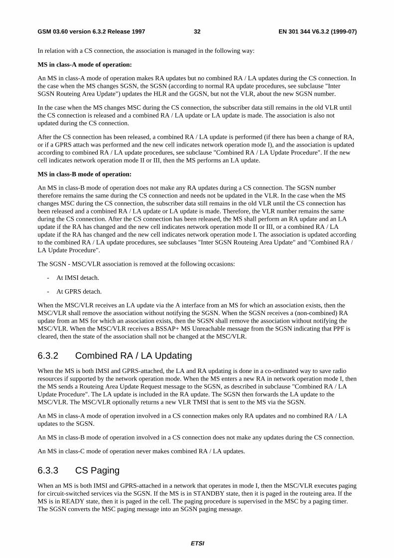
ETSI
EN 301 344 V6.3.2 (1999-07)32GSM 03.60 version 6.3.2 Release 1997
In relation with a CS connection, the association is managed in the following way:
MS in class-A mode of operation:
An MS in class-A mode of operation makes RA updates but no combined RA / LA updates during the CS connection. Inthe case when the MS changes SGSN, the SGSN (according to normal RA update procedures, see subclause "InterSGSN Routeing Area Update") updates the HLR and the GGSN, but not the VLR, about the new SGSN number.
In the case when the MS changes MSC during the CS connection, the subscriber data still remains in the old VLR untilthe CS connection is released and a combined RA / LA update or LA update is made. The association is also notupdated during the CS connection.
After the CS connection has been released, a combined RA / LA update is performed (if there has been a change of RA,or if a GPRS attach was performed and the new cell indicates network operation mode I), and the association is updatedaccording to combined RA / LA update procedures, see subclause "Combined RA / LA Update Procedure". If the newcell indicates network operation mode II or III, then the MS performs an LA update.
MS in class-B mode of operation:
An MS in class-B mode of operation does not make any RA updates during a CS connection. The SGSN numbertherefore remains the same during the CS connection and needs not be updated in the VLR. In the case when the MSchanges MSC during the CS connection, the subscriber data still remains in the old VLR until the CS connection hasbeen released and a combined RA / LA update or LA update is made. Therefore, the VLR number remains the sameduring the CS connection. After the CS connection has been released, the MS shall perform an RA update and an LAupdate if the RA has changed and the new cell indicates network operation mode II or III, or a combined RA / LAupdate if the RA has changed and the new cell indicates network operation mode I. The association is updated accordingto the combined RA / LA update procedures, see subclauses "Inter SGSN Routeing Area Update" and "Combined RA /LA Update Procedure".
The SGSN - MSC/VLR association is removed at the following occasions:
- At IMSI detach.
- At GPRS detach.
When the MSC/VLR receives an LA update via the A interface from an MS for which an association exists, then theMSC/VLR shall remove the association without notifying the SGSN. When the SGSN receives a (non-combined) RAupdate from an MS for which an association exists, then the SGSN shall remove the association without notifying theMSC/VLR. When the MSC/VLR receives a BSSAP+ MS Unreachable message from the SGSN indicating that PPF iscleared, then the state of the association shall not be changed at the MSC/VLR.
6.3.2 Combined RA / LA Updating
When the MS is both IMSI and GPRS-attached, the LA and RA updating is done in a co-ordinated way to save radioresources if supported by the network operation mode. When the MS enters a new RA in network operation mode I, thenthe MS sends a Routeing Area Update Request message to the SGSN, as described in subclause "Combined RA / LAUpdate Procedure". The LA update is included in the RA update. The SGSN then forwards the LA update to theMSC/VLR. The MSC/VLR optionally returns a new VLR TMSI that is sent to the MS via the SGSN.
An MS in class-A mode of operation involved in a CS connection makes only RA updates and no combined RA / LAupdates to the SGSN.
An MS in class-B mode of operation involved in a CS connection does not make any updates during the CS connection.
An MS in class-C mode of operation never makes combined RA / LA updates.
6.3.3 CS Paging
When an MS is both IMSI and GPRS-attached in a network that operates in mode I, then the MSC/VLR executes pagingfor circuit-switched services via the SGSN. If the MS is in STANDBY state, then it is paged in the routeing area. If theMS is in READY state, then it is paged in the cell. The paging procedure is supervised in the MSC by a paging timer.The SGSN converts the MSC paging message into an SGSN paging message.
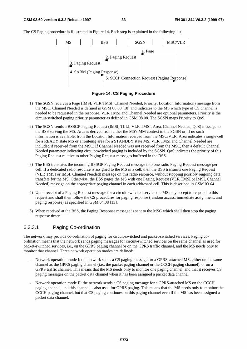
ETSI
EN 301 344 V6.3.2 (1999-07)33GSM 03.60 version 6.3.2 Release 1997
The CS Paging procedure is illustrated in Figure 14. Each step is explained in the following list.
4. SABM (Paging Response)
5. SCCP Connection Request (Paging Response)
1. Page
3. Paging Request
2. Paging Request
MS BSS SGSN MSC/VLR
Figure 14: CS Paging Procedure
1) The SGSN receives a Page (IMSI, VLR TMSI, Channel Needed, Priority, Location Information) message fromthe MSC. Channel Needed is defined in GSM 08.08 [18] and indicates to the MS which type of CS channel isneeded to be requested in the response. VLR TMSI and Channel Needed are optional parameters. Priority is thecircuit-switched paging priority parameter as defined in GSM 08.08. The SGSN maps Priority to QoS.
2) The SGSN sends a BSSGP Paging Request (IMSI, TLLI, VLR TMSI, Area, Channel Needed, QoS) message tothe BSS serving the MS. Area is derived from either the MS's MM context in the SGSN or, if no suchinformation is available, from the Location Information received from the MSC/VLR. Area indicates a single cellfor a READY state MS or a routeing area for a STANDBY state MS. VLR TMSI and Channel Needed areincluded if received from the MSC. If Channel Needed was not received from the MSC, then a default ChannelNeeded parameter indicating circuit-switched paging is included by the SGSN. QoS indicates the priority of thisPaging Request relative to other Paging Request messages buffered in the BSS.
3) The BSS translates the incoming BSSGP Paging Request message into one radio Paging Request message percell. If a dedicated radio resource is assigned to the MS in a cell, then the BSS transmits one Paging Request(VLR TMSI or IMSI, Channel Needed) message on this radio resource, without stopping possibly ongoing datatransfers for the MS. Otherwise, the BSS pages the MS with one Paging Request (VLR TMSI or IMSI, ChannelNeeded) message on the appropriate paging channel in each addressed cell. This is described in GSM 03.64.
4) Upon receipt of a Paging Request message for a circuit-switched service the MS may accept to respond to thisrequest and shall then follow the CS procedures for paging response (random access, immediate assignment, andpaging response) as specified in GSM 04.08 [13].
5) When received at the BSS, the Paging Response message is sent to the MSC which shall then stop the pagingresponse timer.
6.3.3.1 Paging Co-ordination
The network may provide co-ordination of paging for circuit-switched and packet-switched services. Paging co-ordination means that the network sends paging messages for circuit-switched services on the same channel as used forpacket-switched services, i.e., on the GPRS paging channel or on the GPRS traffic channel, and the MS needs only tomonitor that channel. Three network operation modes are defined:
- Network operation mode I: the network sends a CS paging message for a GPRS-attached MS, either on the samechannel as the GPRS paging channel (i.e., the packet paging channel or the CCCH paging channel), or on aGPRS traffic channel. This means that the MS needs only to monitor one paging channel, and that it receives CSpaging messages on the packet data channel when it has been assigned a packet data channel.
- Network operation mode II: the network sends a CS paging message for a GPRS-attached MS on the CCCHpaging channel, and this channel is also used for GPRS paging. This means that the MS needs only to monitor theCCCH paging channel, but that CS paging continues on this paging channel even if the MS has been assigned apacket data channel.
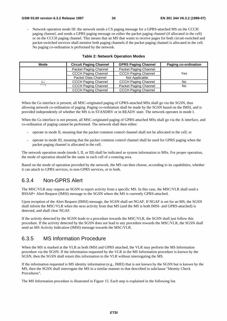
ETSI
EN 301 344 V6.3.2 (1999-07)34GSM 03.60 version 6.3.2 Release 1997
- Network operation mode III: the network sends a CS paging message for a GPRS-attached MS on the CCCHpaging channel, and sends a GPRS paging message on either the packet paging channel (if allocated in the cell)or on the CCCH paging channel. This means that an MS that wants to receive pages for both circuit-switched andpacket-switched services shall monitor both paging channels if the packet paging channel is allocated in the cell.No paging co-ordination is performed by the network.
Table 2: Network Operation Modes
Mode Circuit Paging Channel GPRS Paging Channel Paging co-ordinationPacket Paging Channel Packet Paging Channel
, CCCH Paging Channel CCCH Paging Channel YesPacket Data Channel Not Applicable
,, CCCH Paging Channel CCCH Paging Channel No,,, CCCH Paging Channel Packet Paging Channel No
CCCH Paging Channel CCCH Paging Channel
When the Gs interface is present, all MSC-originated paging of GPRS-attached MSs shall go via the SGSN, thusallowing network co-ordination of paging. Paging co-ordination shall be made by the SGSN based on the IMSI, and isprovided independently of whether the MS is in STANDBY or in READY state. The network operates in mode I.
When the Gs interface is not present, all MSC-originated paging of GPRS-attached MSs shall go via the A interface, andco-ordination of paging cannot be performed. The network shall then either:
- operate in mode II, meaning that the packet common control channel shall not be allocated in the cell; or
- operate in mode III, meaning that the packet common control channel shall be used for GPRS paging when thepacket paging channel is allocated in the cell.
The network operation mode (mode I, II, or III) shall be indicated as system information to MSs. For proper operation,the mode of operation should be the same in each cell of a routeing area.
Based on the mode of operation provided by the network, the MS can then choose, according to its capabilities, whetherit can attach to GPRS services, to non-GPRS services, or to both.
6.3.4 Non-GPRS Alert
The MSC/VLR may request an SGSN to report activity from a specific MS. In this case, the MSC/VLR shall send aBSSAP+ Alert Request (IMSI) message to the SGSN where the MS is currently GPRS-attached.
Upon reception of the Alert Request (IMSI) message, the SGSN shall set NGAF. If NGAF is set for an MS, the SGSNshall inform the MSC/VLR when the next activity from that MS (and the MS is both IMSI- and GPRS-attached) isdetected, and shall clear NGAF.
If the activity detected by the SGSN leads to a procedure towards the MSC/VLR, the SGSN shall just follow thisprocedure. If the activity detected by the SGSN does not lead to any procedure towards the MSC/VLR, the SGSN shallsend an MS Activity Indication (IMSI) message towards the MSC/VLR.
6.3.5 MS Information Procedure
When the MS is marked at the VLR as both IMSI and GPRS attached, the VLR may perform the MS Informationprocedure via the SGSN. If the information requested by the VLR in the MS Information procedure is known by theSGSN, then the SGSN shall return this information to the VLR without interrogating the MS.
If the information requested is MS identity information (e.g., IMEI) that is not known by the SGSN but is known by theMS, then the SGSN shall interrogate the MS in a similar manner to that described in subclause "Identity CheckProcedures".
The MS Information procedure is illustrated in Figure 15. Each step is explained in the following list.
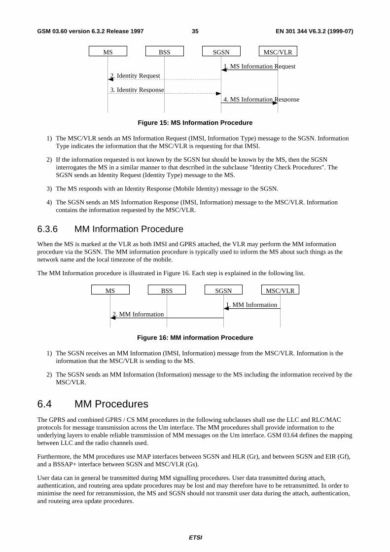
ETSI
EN 301 344 V6.3.2 (1999-07)35GSM 03.60 version 6.3.2 Release 1997
BSS SGSN MSC/VLR
1. MS Information Request
MS
2. Identity Request
4. MS Information Response
3. Identity Response
Figure 15: MS Information Procedure
1) The MSC/VLR sends an MS Information Request (IMSI, Information Type) message to the SGSN. InformationType indicates the information that the MSC/VLR is requesting for that IMSI.
2) If the information requested is not known by the SGSN but should be known by the MS, then the SGSNinterrogates the MS in a similar manner to that described in the subclause "Identity Check Procedures". TheSGSN sends an Identity Request (Identity Type) message to the MS.
3) The MS responds with an Identity Response (Mobile Identity) message to the SGSN.
4) The SGSN sends an MS Information Response (IMSI, Information) message to the MSC/VLR. Informationcontains the information requested by the MSC/VLR.
6.3.6 MM Information Procedure
When the MS is marked at the VLR as both IMSI and GPRS attached, the VLR may perform the MM informationprocedure via the SGSN. The MM information procedure is typically used to inform the MS about such things as thenetwork name and the local timezone of the mobile.
The MM Information procedure is illustrated in Figure 16. Each step is explained in the following list.
BSS SGSN MSC/VLR
1. MM Information
MS
2. MM Information
Figure 16: MM information Procedure
1) The SGSN receives an MM Information (IMSI, Information) message from the MSC/VLR. Information is theinformation that the MSC/VLR is sending to the MS.
2) The SGSN sends an MM Information (Information) message to the MS including the information received by theMSC/VLR.
6.4 MM ProceduresThe GPRS and combined GPRS / CS MM procedures in the following subclauses shall use the LLC and RLC/MACprotocols for message transmission across the Um interface. The MM procedures shall provide information to theunderlying layers to enable reliable transmission of MM messages on the Um interface. GSM 03.64 defines the mappingbetween LLC and the radio channels used.
Furthermore, the MM procedures use MAP interfaces between SGSN and HLR (Gr), and between SGSN and EIR (Gf),and a BSSAP+ interface between SGSN and MSC/VLR (Gs).
User data can in general be transmitted during MM signalling procedures. User data transmitted during attach,authentication, and routeing area update procedures may be lost and may therefore have to be retransmitted. In order tominimise the need for retransmission, the MS and SGSN should not transmit user data during the attach, authentication,and routeing area update procedures.
ETSI
EN 301 344 V6.3.2 (1999-07)36GSM 03.60 version 6.3.2 Release 1997
6.5 Attach FunctionA GPRS attach is made to the SGSN. A GPRS-attached MS makes IMSI attach via the SGSN with the combined RA /LA update procedure if the network operation mode is I. In network operation modes II and III, or if the MS is notGPRS-attached, then the MS makes IMSI attach as already defined in GSM. An IMSI-attached MS in class-A mode ofoperation engaged in a CS connection shall use the (non-combined) GPRS Attach procedure when it performs a GPRSattach.
In the attach procedure, the MS shall provide its identity and an indication of which type of attach that is to be executed.The identity provided to the network shall be the MS's Packet TMSI (P-TMSI) or IMSI. P-TMSI and the RAI associatedwith the P-TMSI shall be provided if the MS has a valid P-TMSI. If the MS does not have a valid P-TMSI, then the MSshall provide its IMSI. The different types of attach are GPRS attach and combined GPRS / IMSI attach.
At the RLC/MAC layer, the MS shall identify itself with a Local or Foreign TLLI if the MS is already GPRS-attachedand is performing an IMSI attach. Otherwise, the MS shall identify itself with a Foreign TLLI, or a Random TLLI if avalid P-TMSI is not available. The Foreign or Random TLLI is used as an identifier during the attach procedure until anew P-TMSI is allocated.
After having executed the GPRS attach, the MS is in READY state and MM contexts are established in the MS and theSGSN. The MS may then activate PDP contexts as described in subclause "Activation Procedures".
An IMSI-attached MS that can only operate in class-C mode of operation shall follow the normal IMSI detachprocedure before it makes a GPRS attach. A GPRS-attached MS in class-C mode of operation shall always perform aGPRS detach before it makes an IMSI attach.
If the network operates in mode I (see subclause "Paging Co-ordination"), then an MS that is both GPRS-attached andIMSI-attached shall perform the Combined RA / LA Update procedures.
If the network operates in mode II or III, then a GPRS-attached MS that has the capability to be simultaneously GPRS-attached and IMSI-attached shall perform the (non-combined) Routeing Area Update procedures, and either:
- access the non-GPRS common control channels for CS operation (the way that CS operation is performed inparallel with GPRS operation is an MS implementation issue outside the scope of the present document); or
- if CS operation is not desired, depending on system information that defines whether or not explicit detach shallbe used, either:
- avoid all CS signalling (in which case the MS may be implicitly IMSI detached after a while); or
- perform an explicit IMSI detach via the non-GPRS common control channels (if the MS was already IMSI-attached).
The Combined GPRS / IMSI Attach procedure is illustrated in Figure 17. Each step is explained in the following list.
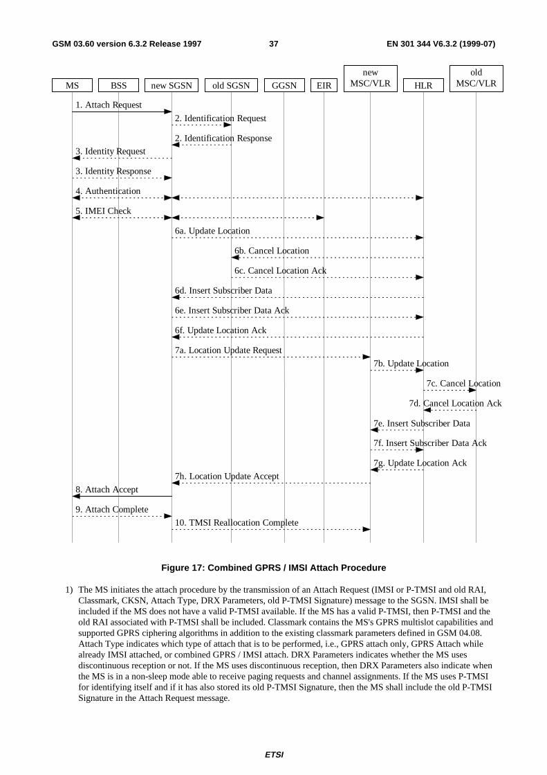
ETSI
EN 301 344 V6.3.2 (1999-07)37GSM 03.60 version 6.3.2 Release 1997
7d. Cancel Location Ack
7c. Cancel Location
7b. Update Location
7g. Update Location Ack
7e. Insert Subscriber Data
7f. Insert Subscriber Data Ack
6d. Insert Subscriber Data
6c. Cancel Location Ack
6b. Cancel Location
3. Identity Response
2. Identification Response
2. Identification Request
1. Attach Request
5. IMEI Check
3. Identity Request
4. Authentication
6a. Update Location
7a. Location Update Request
7h. Location Update Accept
6f. Update Location Ack
6e. Insert Subscriber Data Ack
MS BSS new SGSN old SGSN GGSN HLREIR
oldMSC/VLR
newMSC/VLR
9. Attach Complete
8. Attach Accept
10. TMSI Reallocation Complete
Figure 17: Combined GPRS / IMSI Attach Procedure
1) The MS initiates the attach procedure by the transmission of an Attach Request (IMSI or P-TMSI and old RAI,Classmark, CKSN, Attach Type, DRX Parameters, old P-TMSI Signature) message to the SGSN. IMSI shall beincluded if the MS does not have a valid P-TMSI available. If the MS has a valid P-TMSI, then P-TMSI and theold RAI associated with P-TMSI shall be included. Classmark contains the MS's GPRS multislot capabilities andsupported GPRS ciphering algorithms in addition to the existing classmark parameters defined in GSM 04.08.Attach Type indicates which type of attach that is to be performed, i.e., GPRS attach only, GPRS Attach whilealready IMSI attached, or combined GPRS / IMSI attach. DRX Parameters indicates whether the MS usesdiscontinuous reception or not. If the MS uses discontinuous reception, then DRX Parameters also indicate whenthe MS is in a non-sleep mode able to receive paging requests and channel assignments. If the MS uses P-TMSIfor identifying itself and if it has also stored its old P-TMSI Signature, then the MS shall include the old P-TMSISignature in the Attach Request message.
ETSI
EN 301 344 V6.3.2 (1999-07)38GSM 03.60 version 6.3.2 Release 1997
2) If the MS identifies itself with P-TMSI and the SGSN has changed since detach, the new SGSN sends anIdentification Request (P-TMSI, old RAI, old P-TMSI Signature) to the old SGSN to request the IMSI. The oldSGSN responds with Identification Response (IMSI, Authentication Triplets). If the MS is not known in the oldSGSN, the old SGSN responds with an appropriate error cause. The old SGSN also validates the old P-TMSISignature and responds with an appropriate error cause if it does not match the value stored in the old SGSN.
3) If the MS is unknown in both the old and new SGSN, the SGSN sends an Identity Request (Identity Type =IMSI) to the MS. The MS responds with Identity Response (IMSI).
4) The authentication functions are defined in the subclause "Security Function". If no MM context for the MSexists anywhere in the network, then authentication is mandatory. Ciphering procedures are described insubclause "Security Function". If P-TMSI allocation is going to be done, and if ciphering is supported by thenetwork, ciphering mode shall be set.
5) The equipment checking functions are defined in the subclause "Identity Check Procedures". Equipmentchecking is optional.
6) If the SGSN number has changed since the GPRS detach, or if it is the very first attach, then the SGSN informsthe HLR:
a) The SGSN sends an Update Location (SGSN Number, SGSN Address, IMSI) to the HLR.
b) The HLR sends Cancel Location (IMSI, Cancellation Type) to the old SGSN with Cancellation Type set toUpdate Procedure.
c) The old SGSN acknowledges with Cancel Location Ack (IMSI). If there are any ongoing procedures for thatMS, the old SGSN shall wait until these procedures are finished before removing the MM and PDP contexts.
d) The HLR sends Insert Subscriber Data (IMSI, GPRS subscription data) to the new SGSN.
e) The new SGSN validates the MS's presence in the (new) RA. If due to regional subscription restrictions theMS is not allowed to attach in the RA, the SGSN rejects the Attach Request with an appropriate cause, andmay return an Insert Subscriber Data Ack (IMSI, SGSN Area Restricted) message to the HLR. If subscriptionchecking fails for other reasons, the SGSN rejects the Attach Request with an appropriate cause and returnsan Insert Subscriber Data Ack (IMSI, Cause) message to the HLR. If all checks are successful then the SGSNconstructs an MM context for the MS and returns an Insert Subscriber Data Ack (IMSI) message to the HLR.
f) The HLR acknowledges the Update Location message by sending an Update Location Ack to the SGSN afterthe cancelling of old MM context and insertion of new MM context are finished. If the Update Location isrejected by the HLR, the SGSN rejects the Attach Request from the MS with an appropriate cause.
7) If Attach Type in step 1 indicated GPRS Attach while already IMSI attached, or combined GPRS / IMSI attach,then the VLR shall be updated if the Gs interface is installed. The VLR number is derived from the RAinformation. The SGSN starts the location update procedure towards the new MSC/VLR upon receipt of the firstInsert Subscriber Data message from the HLR in step 6 d). This operation marks the MS as GPRS-attached in theVLR.
a) The SGSN sends a Location Update Request (new LAI, IMSI, SGSN Number, Location Update Type)message to the VLR. Location Update Type shall indicate IMSI attach if Attach Type indicated combinedGPRS / IMSI attach. Otherwise, Location Update Type shall indicate normal location update. The VLRcreates an association with the SGSN by storing SGSN Number.
b) If the LA update is inter-MSC, the new VLR sends Update Location (IMSI, new VLR) to the HLR.
c) If the LA update is inter-MSC, the HLR sends a Cancel Location (IMSI) to the old VLR.
d) The old VLR acknowledges with Cancel Location Ack (IMSI).
e) If the LA update is inter-MSC, the HLR sends Insert Subscriber Data (IMSI, GSM subscriber data) to thenew VLR.
f) The VLR acknowledges with Insert Subscriber Data Ack (IMSI).
ETSI
EN 301 344 V6.3.2 (1999-07)39GSM 03.60 version 6.3.2 Release 1997
g) After finishing the inter-MSC location update procedures, the HLR responds with Update Location Ack(IMSI) to the new VLR.
h) The VLR responds with Location Update Accept (VLR TMSI) to the SGSN.
8) The SGSN selects Radio Priority SMS, and sends an Attach Accept (P-TMSI, VLR TMSI, P-TMSI Signature,Radio Priority SMS) message to the MS. P-TMSI is included if the SGSN allocates a new P-TMSI.
9) If P-TMSI or VLR TMSI was changed, the MS acknowledges the received TMSI(s) with Attach Complete(P-TMSI, VLR TMSI).
10)If VLR TMSI was changed, the SGSN confirms the VLR TMSI re-allocation by sending TMSI ReallocationComplete (VLR TMSI) to the VLR.
If the Attach Request cannot be accepted, the SGSN returns an Attach Reject (IMSI, Cause) message to the MS.
6.6 Detach FunctionThe Detach function allows an MS to inform the network that it wants to make a GPRS and/or IMSI detach, and itallows the network to inform an MS that it has been GPRS-detached or IMSI-detached by the network. The differenttypes of detach are:
- IMSI detach;
- GPRS detach; and
- combined GPRS / IMSI detach (MS-initiated only).
The MS is detached from GPRS either explicitly or implicitly:
- Explicit detach: The network or the MS explicitly requests detach.
- Implicit detach: The network detaches the MS, without notifiying the MS, a configuration-dependent time afterthe mobile reachable timer expired, or after an irrecoverable radio error causes disconnection of the logical link.
In the explicit detach case, a Detach Request (Cause) is sent by the SGSN to the MS, or by the MS to the SGSN.
The MS can make an IMSI detach in one of two ways depending on if it is GPRS-attached or not:
- A GPRS-attached MS sends a Detach Request message to the SGSN, indicating an IMSI detach. This can bemade in combination with GPRS detach.
- An MS not attached to the GPRS makes the IMSI detach as already defined in GSM.
In the MO Detach Request message there is an indication to tell if the detach is due to switch off or not. The indicationis needed to know whether a Detach Accept message should be returned or not.
In the network-originated Detach Request message there may be an indication to tell the MS that it is requested toinitiate GPRS Attach and PDP Context Activation procedures for the previously activated PDP contexts.
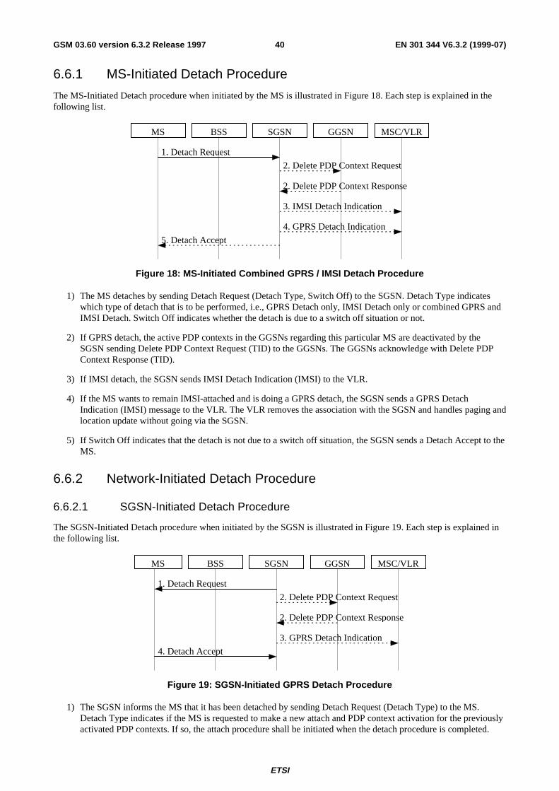
ETSI
EN 301 344 V6.3.2 (1999-07)40GSM 03.60 version 6.3.2 Release 1997
6.6.1 MS-Initiated Detach Procedure
The MS-Initiated Detach procedure when initiated by the MS is illustrated in Figure 18. Each step is explained in thefollowing list.
3. IMSI Detach Indication
2. Delete PDP Context Response
1. Detach Request
2. Delete PDP Context Request
5. Detach Accept
MS BSS GGSNSGSN MSC/VLR
4. GPRS Detach Indication
Figure 18: MS-Initiated Combined GPRS / IMSI Detach Procedure
1) The MS detaches by sending Detach Request (Detach Type, Switch Off) to the SGSN. Detach Type indicateswhich type of detach that is to be performed, i.e., GPRS Detach only, IMSI Detach only or combined GPRS andIMSI Detach. Switch Off indicates whether the detach is due to a switch off situation or not.
2) If GPRS detach, the active PDP contexts in the GGSNs regarding this particular MS are deactivated by theSGSN sending Delete PDP Context Request (TID) to the GGSNs. The GGSNs acknowledge with Delete PDPContext Response (TID).
3) If IMSI detach, the SGSN sends IMSI Detach Indication (IMSI) to the VLR.
4) If the MS wants to remain IMSI-attached and is doing a GPRS detach, the SGSN sends a GPRS DetachIndication (IMSI) message to the VLR. The VLR removes the association with the SGSN and handles paging andlocation update without going via the SGSN.
5) If Switch Off indicates that the detach is not due to a switch off situation, the SGSN sends a Detach Accept to theMS.
6.6.2 Network-Initiated Detach Procedure
6.6.2.1 SGSN-Initiated Detach Procedure
The SGSN-Initiated Detach procedure when initiated by the SGSN is illustrated in Figure 19. Each step is explained inthe following list.
2. Delete PDP Context Response
1. Detach Request
2. Delete PDP Context Request
4. Detach Accept
MS BSS GGSNSGSN MSC/VLR
3. GPRS Detach Indication
Figure 19: SGSN-Initiated GPRS Detach Procedure
1) The SGSN informs the MS that it has been detached by sending Detach Request (Detach Type) to the MS.Detach Type indicates if the MS is requested to make a new attach and PDP context activation for the previouslyactivated PDP contexts. If so, the attach procedure shall be initiated when the detach procedure is completed.
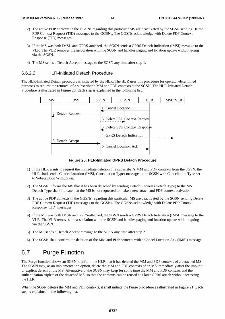
ETSI
EN 301 344 V6.3.2 (1999-07)41GSM 03.60 version 6.3.2 Release 1997
2) The active PDP contexts in the GGSNs regarding this particular MS are deactivated by the SGSN sending DeletePDP Context Request (TID) messages to the GGSNs. The GGSNs acknowledge with Delete PDP ContextResponse (TID) messages.
3) If the MS was both IMSI- and GPRS-attached, the SGSN sends a GPRS Detach Indication (IMSI) message to theVLR. The VLR removes the association with the SGSN and handles paging and location update without goingvia the SGSN.
4) The MS sends a Detach Accept message to the SGSN any time after step 1.
6.6.2.2 HLR-Initiated Detach Procedure
The HLR-Initiated Detach procedure is initiated by the HLR. The HLR uses this procedure for operator-determinedpurposes to request the removal of a subscriber’s MM and PDP contexts at the SGSN. The HLR-Initiated DetachProcedure is illustrated in Figure 20. Each step is explained in the following list.
HLRMS BSS GGSNSGSN MSC/VLR
3. Delete PDP Context Request
1. Cancel Location
4. GPRS Detach Indication
2. Detach Request
6. Cancel Location Ack
3. Delete PDP Context Response
5. Detach Accept
Figure 20: HLR-Initiated GPRS Detach Procedure
1) If the HLR wants to request the immediate deletion of a subscriber’s MM and PDP contexts from the SGSN, theHLR shall send a Cancel Location (IMSI, Cancellation Type) message to the SGSN with Cancellation Type setto Subscription Withdrawn.
2) The SGSN informs the MS that it has been detached by sending Detach Request (Detach Type) to the MS.Detach Type shall indicate that the MS is not requested to make a new attach and PDP context activation.
3) The active PDP contexts in the GGSNs regarding this particular MS are deactivated by the SGSN sending DeletePDP Context Request (TID) messages to the GGSNs. The GGSNs acknowledge with Delete PDP ContextResponse (TID) messages.
4) If the MS was both IMSI- and GPRS-attached, the SGSN sends a GPRS Detach Indication (IMSI) message to theVLR. The VLR removes the association with the SGSN and handles paging and location update without goingvia the SGSN.
5) The MS sends a Detach Accept message to the SGSN any time after step 2.
6) The SGSN shall confirm the deletion of the MM and PDP contexts with a Cancel Location Ack (IMSI) message.
6.7 Purge FunctionThe Purge function allows an SGSN to inform the HLR that it has deleted the MM and PDP contexts of a detached MS.The SGSN may, as an implementation option, delete the MM and PDP contexts of an MS immediately after the implicitor explicit detach of the MS. Alternatively, the SGSN may keep for some time the MM and PDP contexts and theauthentication triplets of the detached MS, so that the contexts can be reused at a later GPRS attach without accessingthe HLR.
When the SGSN deletes the MM and PDP contexts, it shall initiate the Purge procedure as illustrated in Figure 21. Eachstep is explained in the following list.
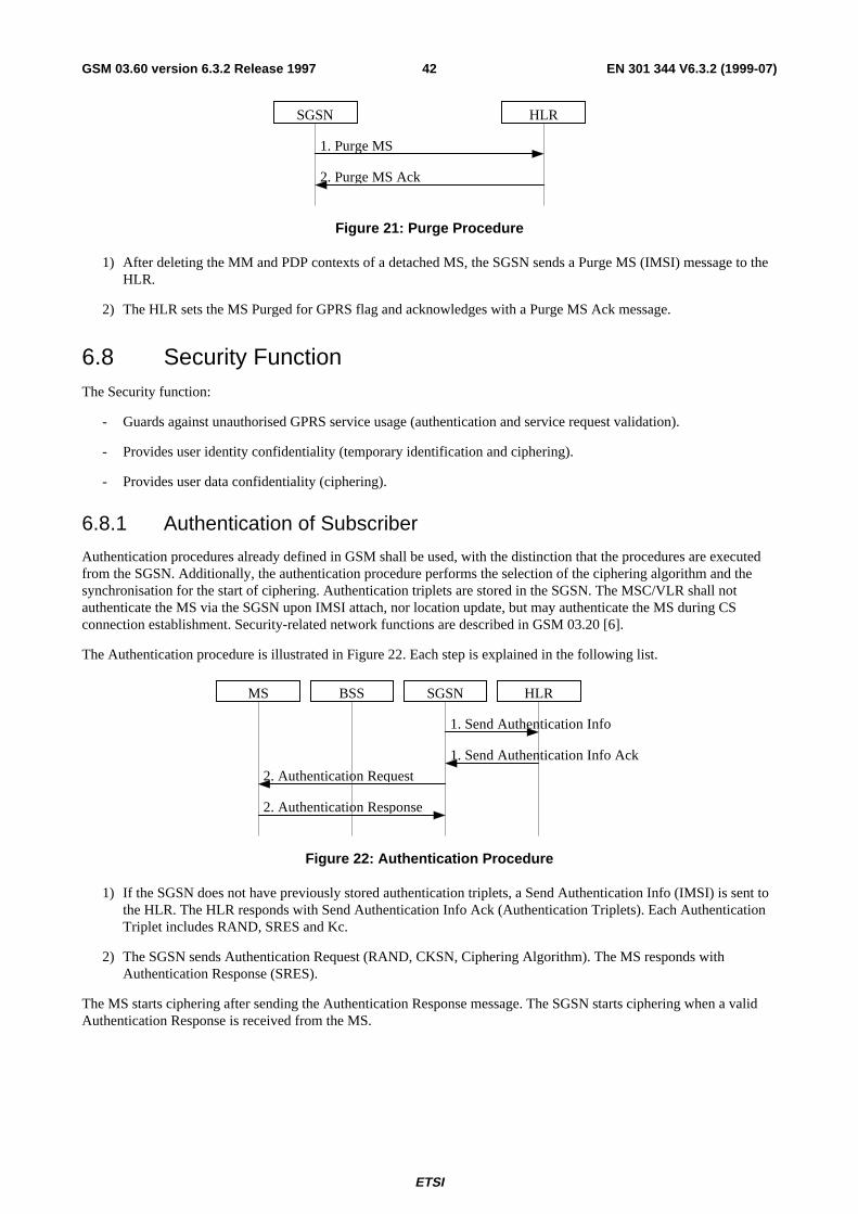
ETSI
EN 301 344 V6.3.2 (1999-07)42GSM 03.60 version 6.3.2 Release 1997
1. Purge MS
2. Purge MS Ack
SGSN HLR
Figure 21: Purge Procedure
1) After deleting the MM and PDP contexts of a detached MS, the SGSN sends a Purge MS (IMSI) message to theHLR.
2) The HLR sets the MS Purged for GPRS flag and acknowledges with a Purge MS Ack message.
6.8 Security FunctionThe Security function:
- Guards against unauthorised GPRS service usage (authentication and service request validation).
- Provides user identity confidentiality (temporary identification and ciphering).
- Provides user data confidentiality (ciphering).
6.8.1 Authentication of Subscriber
Authentication procedures already defined in GSM shall be used, with the distinction that the procedures are executedfrom the SGSN. Additionally, the authentication procedure performs the selection of the ciphering algorithm and thesynchronisation for the start of ciphering. Authentication triplets are stored in the SGSN. The MSC/VLR shall notauthenticate the MS via the SGSN upon IMSI attach, nor location update, but may authenticate the MS during CSconnection establishment. Security-related network functions are described in GSM 03.20 [6].
The Authentication procedure is illustrated in Figure 22. Each step is explained in the following list.
1. Send Authentication Info
2. Authentication Request
1. Send Authentication Info Ack
2. Authentication Response
MS BSS HLRSGSN
Figure 22: Authentication Procedure
1) If the SGSN does not have previously stored authentication triplets, a Send Authentication Info (IMSI) is sent tothe HLR. The HLR responds with Send Authentication Info Ack (Authentication Triplets). Each AuthenticationTriplet includes RAND, SRES and Kc.
2) The SGSN sends Authentication Request (RAND, CKSN, Ciphering Algorithm). The MS responds withAuthentication Response (SRES).
The MS starts ciphering after sending the Authentication Response message. The SGSN starts ciphering when a validAuthentication Response is received from the MS.
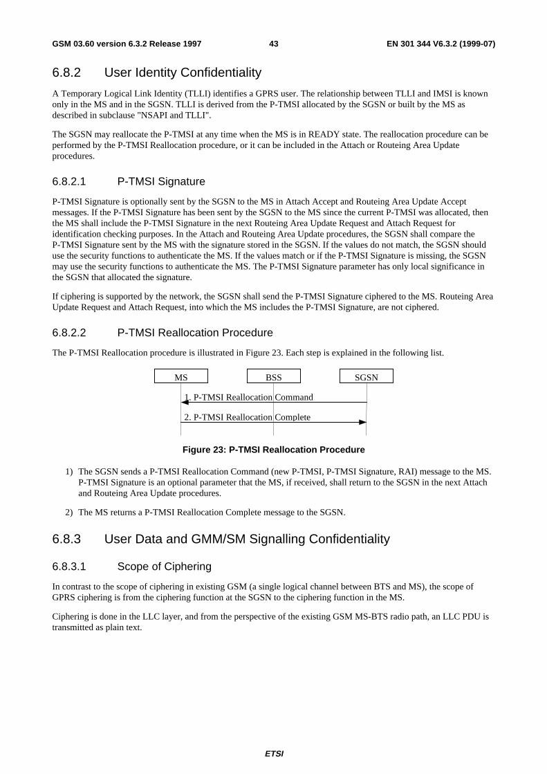
ETSI
EN 301 344 V6.3.2 (1999-07)43GSM 03.60 version 6.3.2 Release 1997
6.8.2 User Identity Confidentiality
A Temporary Logical Link Identity (TLLI) identifies a GPRS user. The relationship between TLLI and IMSI is knownonly in the MS and in the SGSN. TLLI is derived from the P-TMSI allocated by the SGSN or built by the MS asdescribed in subclause "NSAPI and TLLI".
The SGSN may reallocate the P-TMSI at any time when the MS is in READY state. The reallocation procedure can beperformed by the P-TMSI Reallocation procedure, or it can be included in the Attach or Routeing Area Updateprocedures.
6.8.2.1 P-TMSI Signature
P-TMSI Signature is optionally sent by the SGSN to the MS in Attach Accept and Routeing Area Update Acceptmessages. If the P-TMSI Signature has been sent by the SGSN to the MS since the current P-TMSI was allocated, thenthe MS shall include the P-TMSI Signature in the next Routeing Area Update Request and Attach Request foridentification checking purposes. In the Attach and Routeing Area Update procedures, the SGSN shall compare theP-TMSI Signature sent by the MS with the signature stored in the SGSN. If the values do not match, the SGSN shoulduse the security functions to authenticate the MS. If the values match or if the P-TMSI Signature is missing, the SGSNmay use the security functions to authenticate the MS. The P-TMSI Signature parameter has only local significance inthe SGSN that allocated the signature.
If ciphering is supported by the network, the SGSN shall send the P-TMSI Signature ciphered to the MS. Routeing AreaUpdate Request and Attach Request, into which the MS includes the P-TMSI Signature, are not ciphered.
6.8.2.2 P-TMSI Reallocation Procedure
The P-TMSI Reallocation procedure is illustrated in Figure 23. Each step is explained in the following list.
2. P-TMSI Reallocation Complete
1. P-TMSI Reallocation Command
MS BSS SGSN
Figure 23: P-TMSI Reallocation Procedure
1) The SGSN sends a P-TMSI Reallocation Command (new P-TMSI, P-TMSI Signature, RAI) message to the MS.P-TMSI Signature is an optional parameter that the MS, if received, shall return to the SGSN in the next Attachand Routeing Area Update procedures.
2) The MS returns a P-TMSI Reallocation Complete message to the SGSN.
6.8.3 User Data and GMM/SM Signalling Confidentiality
6.8.3.1 Scope of Ciphering
In contrast to the scope of ciphering in existing GSM (a single logical channel between BTS and MS), the scope ofGPRS ciphering is from the ciphering function at the SGSN to the ciphering function in the MS.
Ciphering is done in the LLC layer, and from the perspective of the existing GSM MS-BTS radio path, an LLC PDU istransmitted as plain text.
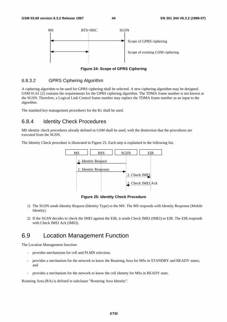
ETSI
EN 301 344 V6.3.2 (1999-07)44GSM 03.60 version 6.3.2 Release 1997
MS BTS+BSC SGSN
Scope of GPRS ciphering
Scope of existing GSM ciphering
Figure 24: Scope of GPRS Ciphering
6.8.3.2 GPRS Ciphering Algorithm
A ciphering algorithm to be used for GPRS ciphering shall be selected. A new ciphering algorithm may be designed.GSM 01.61 [2] contains the requirements for the GPRS ciphering algorithm. The TDMA frame number is not known atthe SGSN. Therefore, a Logical Link Control frame number may replace the TDMA frame number as an input to thealgorithm.
The standard key management procedures for the Kc shall be used.
6.8.4 Identity Check Procedures
MS identity check procedures already defined in GSM shall be used, with the distinction that the procedures areexecuted from the SGSN.
The Identity Check procedure is illustrated in Figure 25. Each step is explained in the following list.
1. Identity Response
2. Check IMEI
1. Identity Request
2. Check IMEI Ack
MS BSS EIRSGSN
Figure 25: Identity Check Procedure
1) The SGSN sends Identity Request (Identity Type) to the MS. The MS responds with Identity Response (MobileIdentity).
2) If the SGSN decides to check the IMEI against the EIR, it sends Check IMEI (IMEI) to EIR. The EIR respondswith Check IMEI Ack (IMEI).
6.9 Location Management FunctionThe Location Management function:
- provides mechanisms for cell and PLMN selection;
- provides a mechanism for the network to know the Routeing Area for MSs in STANDBY and READY states;and
- provides a mechanism for the network to know the cell identity for MSs in READY state.
Routeing Area (RA) is defined in subclause "Routeing Area Identity".
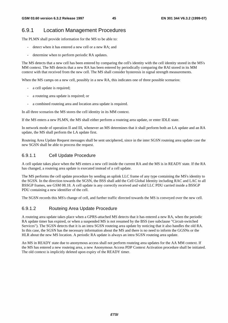
ETSI
EN 301 344 V6.3.2 (1999-07)45GSM 03.60 version 6.3.2 Release 1997
6.9.1 Location Management Procedures
The PLMN shall provide information for the MS to be able to:
- detect when it has entered a new cell or a new RA; and
- determine when to perform periodic RA updates.
The MS detects that a new cell has been entered by comparing the cell's identity with the cell identity stored in the MS'sMM context. The MS detects that a new RA has been entered by periodically comparing the RAI stored in its MMcontext with that received from the new cell. The MS shall consider hysteresis in signal strength measurements.
When the MS camps on a new cell, possibly in a new RA, this indicates one of three possible scenarios:
- a cell update is required;
- a routeing area update is required; or
- a combined routeing area and location area update is required.
In all three scenarios the MS stores the cell identity in its MM context.
If the MS enters a new PLMN, the MS shall either perform a routeing area update, or enter IDLE state.
In network mode of operation II and III, whenever an MS determines that it shall perform both an LA update and an RAupdate, the MS shall perform the LA update first.
Routeing Area Update Request messages shall be sent unciphered, since in the inter SGSN routeing area update case thenew SGSN shall be able to process the request.
6.9.1.1 Cell Update Procedure
A cell update takes place when the MS enters a new cell inside the current RA and the MS is in READY state. If the RAhas changed, a routeing area update is executed instead of a cell update.
The MS performs the cell update procedure by sending an uplink LLC frame of any type containing the MS's identity tothe SGSN. In the direction towards the SGSN, the BSS shall add the Cell Global Identity including RAC and LAC to allBSSGP frames, see GSM 08.18. A cell update is any correctly received and valid LLC PDU carried inside a BSSGPPDU containing a new identifier of the cell.
The SGSN records this MS's change of cell, and further traffic directed towards the MS is conveyed over the new cell.
6.9.1.2 Routeing Area Update Procedure
A routeing area update takes place when a GPRS-attached MS detects that it has entered a new RA, when the periodicRA update timer has expired, or when a suspended MS is not resumed by the BSS (see subclause "Circuit-switchedServices"). The SGSN detects that it is an intra SGSN routeing area update by noticing that it also handles the old RA.In this case, the SGSN has the necessary information about the MS and there is no need to inform the GGSNs or theHLR about the new MS location. A periodic RA update is always an intra SGSN routeing area update.
An MS in READY state due to anonymous access shall not perform routeing area updates for the AA MM context. Ifthe MS has entered a new routeing area, a new Anonymous Access PDP Context Activation procedure shall be initiated.The old context is implicitly deleted upon expiry of the READY timer.
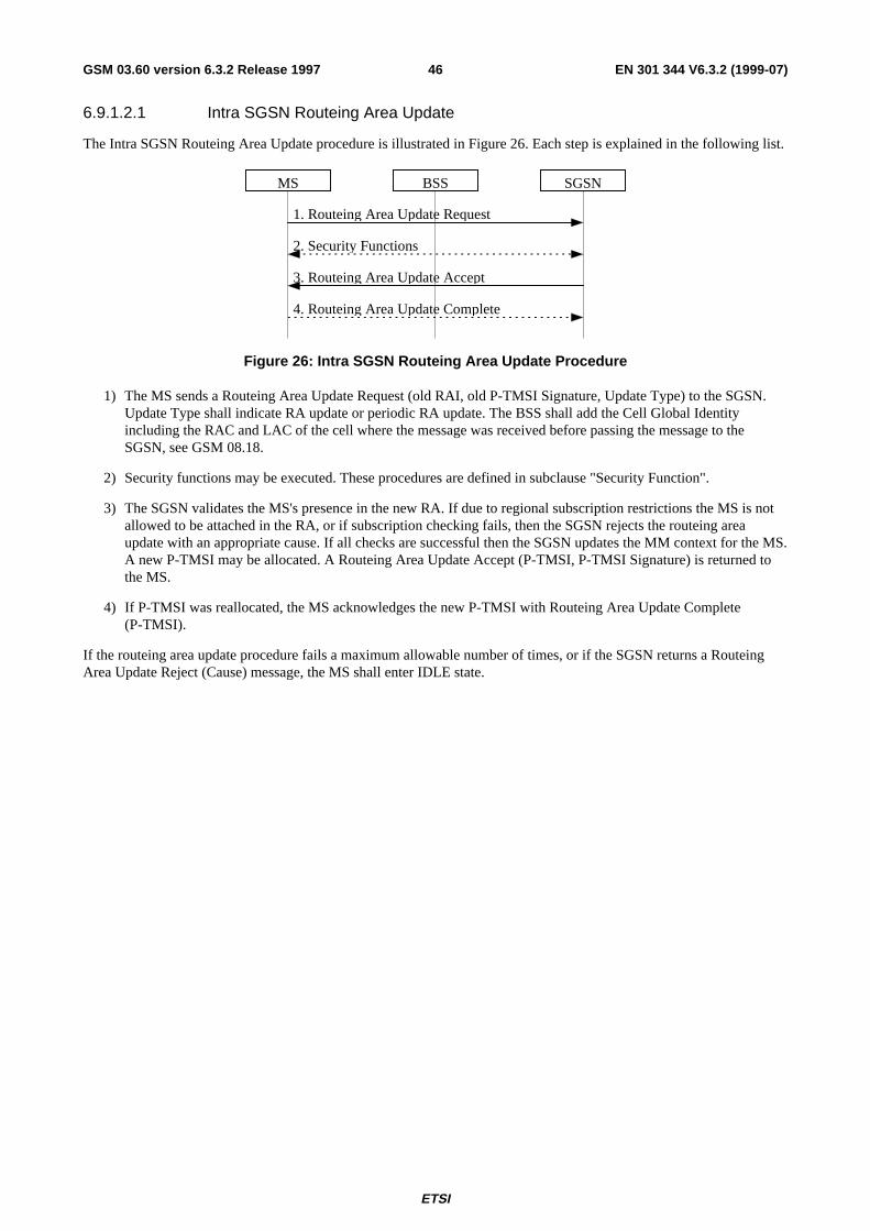
ETSI
EN 301 344 V6.3.2 (1999-07)46GSM 03.60 version 6.3.2 Release 1997
6.9.1.2.1 Intra SGSN Routeing Area Update
The Intra SGSN Routeing Area Update procedure is illustrated in Figure 26. Each step is explained in the following list.
1. Routeing Area Update Request
3. Routeing Area Update Accept
2. Security Functions
MS BSS SGSN
4. Routeing Area Update Complete
Figure 26: Intra SGSN Routeing Area Update Procedure
1) The MS sends a Routeing Area Update Request (old RAI, old P-TMSI Signature, Update Type) to the SGSN.Update Type shall indicate RA update or periodic RA update. The BSS shall add the Cell Global Identityincluding the RAC and LAC of the cell where the message was received before passing the message to theSGSN, see GSM 08.18.
2) Security functions may be executed. These procedures are defined in subclause "Security Function".
3) The SGSN validates the MS's presence in the new RA. If due to regional subscription restrictions the MS is notallowed to be attached in the RA, or if subscription checking fails, then the SGSN rejects the routeing areaupdate with an appropriate cause. If all checks are successful then the SGSN updates the MM context for the MS.A new P-TMSI may be allocated. A Routeing Area Update Accept (P-TMSI, P-TMSI Signature) is returned tothe MS.
4) If P-TMSI was reallocated, the MS acknowledges the new P-TMSI with Routeing Area Update Complete(P-TMSI).
If the routeing area update procedure fails a maximum allowable number of times, or if the SGSN returns a RouteingArea Update Reject (Cause) message, the MS shall enter IDLE state.
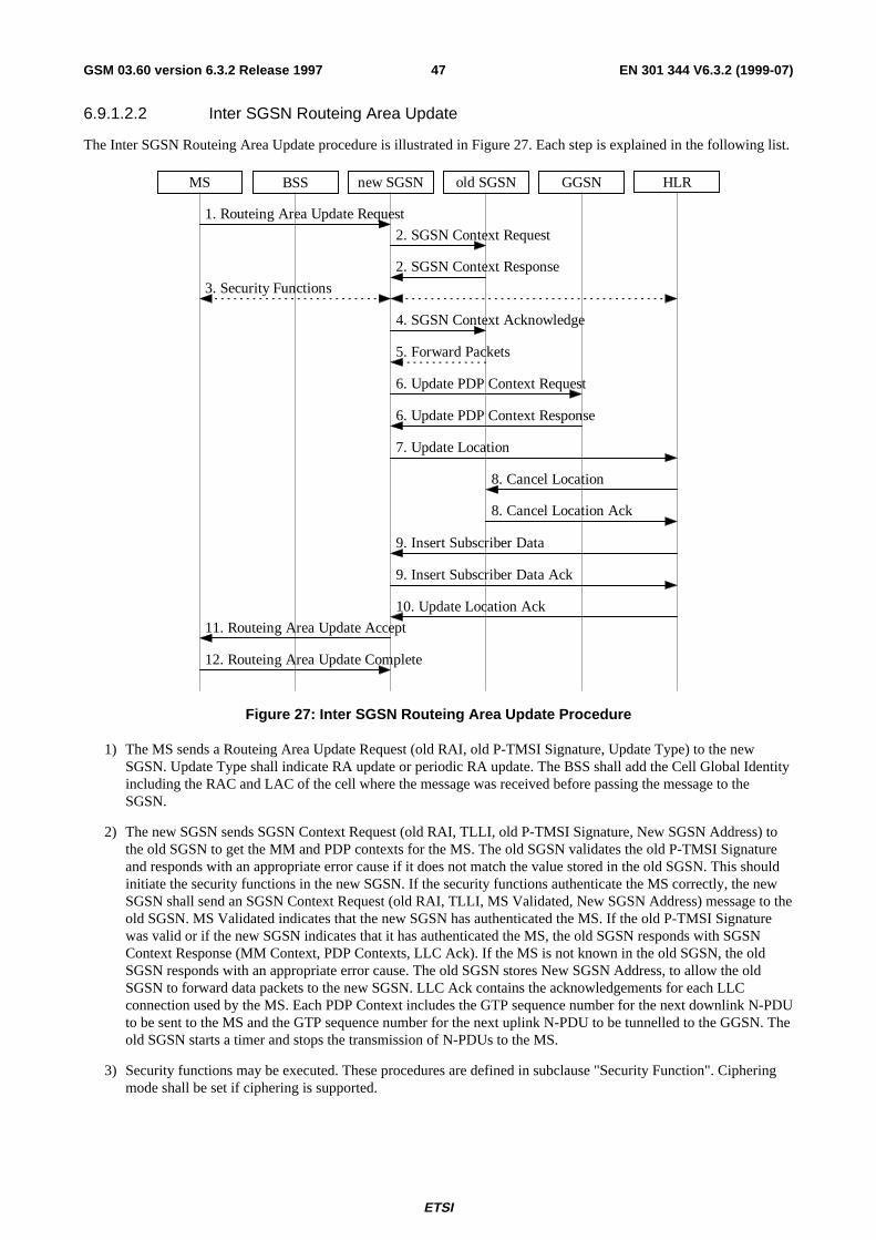
ETSI
EN 301 344 V6.3.2 (1999-07)47GSM 03.60 version 6.3.2 Release 1997
6.9.1.2.2 Inter SGSN Routeing Area Update
The Inter SGSN Routeing Area Update procedure is illustrated in Figure 27. Each step is explained in the following list.
MS BSS new SGSN HLRGGSNold SGSN
2. SGSN Context Response
3. Security Functions
1. Routeing Area Update Request
2. SGSN Context Request
6. Update PDP Context Request
6. Update PDP Context Response
7. Update Location
10. Update Location Ack
11. Routeing Area Update Accept
8. Cancel Location
8. Cancel Location Ack
9. Insert Subscriber Data Ack
9. Insert Subscriber Data
12. Routeing Area Update Complete
5. Forward Packets
4. SGSN Context Acknowledge
Figure 27: Inter SGSN Routeing Area Update Procedure
1) The MS sends a Routeing Area Update Request (old RAI, old P-TMSI Signature, Update Type) to the newSGSN. Update Type shall indicate RA update or periodic RA update. The BSS shall add the Cell Global Identityincluding the RAC and LAC of the cell where the message was received before passing the message to theSGSN.
2) The new SGSN sends SGSN Context Request (old RAI, TLLI, old P-TMSI Signature, New SGSN Address) tothe old SGSN to get the MM and PDP contexts for the MS. The old SGSN validates the old P-TMSI Signatureand responds with an appropriate error cause if it does not match the value stored in the old SGSN. This shouldinitiate the security functions in the new SGSN. If the security functions authenticate the MS correctly, the newSGSN shall send an SGSN Context Request (old RAI, TLLI, MS Validated, New SGSN Address) message to theold SGSN. MS Validated indicates that the new SGSN has authenticated the MS. If the old P-TMSI Signaturewas valid or if the new SGSN indicates that it has authenticated the MS, the old SGSN responds with SGSNContext Response (MM Context, PDP Contexts, LLC Ack). If the MS is not known in the old SGSN, the oldSGSN responds with an appropriate error cause. The old SGSN stores New SGSN Address, to allow the oldSGSN to forward data packets to the new SGSN. LLC Ack contains the acknowledgements for each LLCconnection used by the MS. Each PDP Context includes the GTP sequence number for the next downlink N-PDUto be sent to the MS and the GTP sequence number for the next uplink N-PDU to be tunnelled to the GGSN. Theold SGSN starts a timer and stops the transmission of N-PDUs to the MS.
3) Security functions may be executed. These procedures are defined in subclause "Security Function". Cipheringmode shall be set if ciphering is supported.
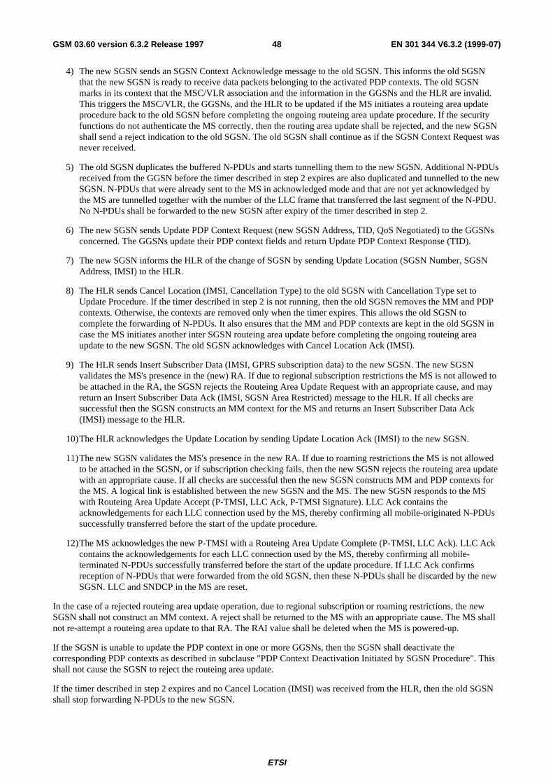
ETSI
EN 301 344 V6.3.2 (1999-07)48GSM 03.60 version 6.3.2 Release 1997
4) The new SGSN sends an SGSN Context Acknowledge message to the old SGSN. This informs the old SGSNthat the new SGSN is ready to receive data packets belonging to the activated PDP contexts. The old SGSNmarks in its context that the MSC/VLR association and the information in the GGSNs and the HLR are invalid.This triggers the MSC/VLR, the GGSNs, and the HLR to be updated if the MS initiates a routeing area updateprocedure back to the old SGSN before completing the ongoing routeing area update procedure. If the securityfunctions do not authenticate the MS correctly, then the routing area update shall be rejected, and the new SGSNshall send a reject indication to the old SGSN. The old SGSN shall continue as if the SGSN Context Request wasnever received.
5) The old SGSN duplicates the buffered N-PDUs and starts tunnelling them to the new SGSN. Additional N-PDUsreceived from the GGSN before the timer described in step 2 expires are also duplicated and tunnelled to the newSGSN. N-PDUs that were already sent to the MS in acknowledged mode and that are not yet acknowledged bythe MS are tunnelled together with the number of the LLC frame that transferred the last segment of the N-PDU.No N-PDUs shall be forwarded to the new SGSN after expiry of the timer described in step 2.
6) The new SGSN sends Update PDP Context Request (new SGSN Address, TID, QoS Negotiated) to the GGSNsconcerned. The GGSNs update their PDP context fields and return Update PDP Context Response (TID).
7) The new SGSN informs the HLR of the change of SGSN by sending Update Location (SGSN Number, SGSNAddress, IMSI) to the HLR.
8) The HLR sends Cancel Location (IMSI, Cancellation Type) to the old SGSN with Cancellation Type set toUpdate Procedure. If the timer described in step 2 is not running, then the old SGSN removes the MM and PDPcontexts. Otherwise, the contexts are removed only when the timer expires. This allows the old SGSN tocomplete the forwarding of N-PDUs. It also ensures that the MM and PDP contexts are kept in the old SGSN incase the MS initiates another inter SGSN routeing area update before completing the ongoing routeing areaupdate to the new SGSN. The old SGSN acknowledges with Cancel Location Ack (IMSI).
9) The HLR sends Insert Subscriber Data (IMSI, GPRS subscription data) to the new SGSN. The new SGSNvalidates the MS's presence in the (new) RA. If due to regional subscription restrictions the MS is not allowed tobe attached in the RA, the SGSN rejects the Routeing Area Update Request with an appropriate cause, and mayreturn an Insert Subscriber Data Ack (IMSI, SGSN Area Restricted) message to the HLR. If all checks aresuccessful then the SGSN constructs an MM context for the MS and returns an Insert Subscriber Data Ack(IMSI) message to the HLR.
10)The HLR acknowledges the Update Location by sending Update Location Ack (IMSI) to the new SGSN.
11)The new SGSN validates the MS's presence in the new RA. If due to roaming restrictions the MS is not allowedto be attached in the SGSN, or if subscription checking fails, then the new SGSN rejects the routeing area updatewith an appropriate cause. If all checks are successful then the new SGSN constructs MM and PDP contexts forthe MS. A logical link is established between the new SGSN and the MS. The new SGSN responds to the MSwith Routeing Area Update Accept (P-TMSI, LLC Ack, P-TMSI Signature). LLC Ack contains theacknowledgements for each LLC connection used by the MS, thereby confirming all mobile-originated N-PDUssuccessfully transferred before the start of the update procedure.
12)The MS acknowledges the new P-TMSI with a Routeing Area Update Complete (P-TMSI, LLC Ack). LLC Ackcontains the acknowledgements for each LLC connection used by the MS, thereby confirming all mobile-terminated N-PDUs successfully transferred before the start of the update procedure. If LLC Ack confirmsreception of N-PDUs that were forwarded from the old SGSN, then these N-PDUs shall be discarded by the newSGSN. LLC and SNDCP in the MS are reset.
In the case of a rejected routeing area update operation, due to regional subscription or roaming restrictions, the newSGSN shall not construct an MM context. A reject shall be returned to the MS with an appropriate cause. The MS shallnot re-attempt a routeing area update to that RA. The RAI value shall be deleted when the MS is powered-up.
If the SGSN is unable to update the PDP context in one or more GGSNs, then the SGSN shall deactivate thecorresponding PDP contexts as described in subclause "PDP Context Deactivation Initiated by SGSN Procedure". Thisshall not cause the SGSN to reject the routeing area update.
If the timer described in step 2 expires and no Cancel Location (IMSI) was received from the HLR, then the old SGSNshall stop forwarding N-PDUs to the new SGSN.
ETSI
EN 301 344 V6.3.2 (1999-07)49GSM 03.60 version 6.3.2 Release 1997
If the routeing area update procedure fails a maximum allowable number of times, or if the SGSN returns a RouteingArea Update Reject (Cause) message, the MS shall enter IDLE state.
6.9.1.3 Combined RA / LA Update Procedure
A combined RA / LA update takes place in network operation mode I when the MS enters a new RA or when a GPRS-attached MS performs IMSI attach. The MS sends a Routeing Area Update Request indicating that an LA update mayalso need to be performed, in which case the SGSN forwards the LA update to the VLR. This concerns only idle mode(see GSM 03.22), as no combined RA / LA updates are performed during a CS connection.
6.9.1.3.1 Combined Intra SGSN RA / LA Update
The Combined RA / LA Update (intra SGSN) procedure is illustrated in Figure 28. Each step is explained in thefollowing list.
4b. Cancel Location
4c. Cancel Location Ack
4e. Insert Subscriber Data Ack
4d. Insert Subscriber Data
HLRMS BSS
newMSC/VLRSGSN
oldMSC/VLR
3. Location Update Request
1. Routeing Area Update Request
2. Security Functions
4a. Update Location
4f. Update Location Ack
8. TMSI Reallocation Complete
6. Routeing Area Update Accept
5. Location Update Accept
7. Routeing Area Update Complete
Figure 28: Combined RA / LA Update in the Case of Intra SGSN RA Update Procedure
1) The MS sends a Routeing Area Update Request (old RAI, old P-TMSI Signature, Update Type) to the SGSN.Update Type shall indicate combined RA / LA update, or, if the MS wants to perform an IMSI attach, combinedRA / LA update with IMSI attach requested. The BSS shall add the Cell Global Identity including the RAC andLAC of the cell where the message was received before passing the message to the SGSN.
2) Security functions may be executed. This procedure is defined in subclause "Security Function".
3) If the association has to be established, if Update Type indicates combined RA / LA update with IMSI attachrequested, or if the LA changed with the routeing area update, then the SGSN sends a Location Update Request(new LAI, IMSI, SGSN Number, Location Update Type) to the VLR. Location Update Type shall indicate IMSIattach if Update Type in step 1 indicated combined RA / LA update with IMSI attach requested. Otherwise,Location Update Type shall indicate normal location update. The VLR number is translated from the RAI via atable in the SGSN. The VLR creates or updates the association with the SGSN by storing SGSN Number.
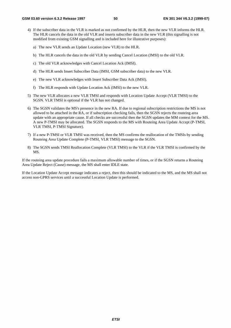
ETSI
EN 301 344 V6.3.2 (1999-07)50GSM 03.60 version 6.3.2 Release 1997
4) If the subscriber data in the VLR is marked as not confirmed by the HLR, then the new VLR informs the HLR.The HLR cancels the data in the old VLR and inserts subscriber data in the new VLR (this signalling is notmodified from existing GSM signalling and is included here for illustrative purposes):
a) The new VLR sends an Update Location (new VLR) to the HLR.
b) The HLR cancels the data in the old VLR by sending Cancel Location (IMSI) to the old VLR.
c) The old VLR acknowledges with Cancel Location Ack (IMSI).
d) The HLR sends Insert Subscriber Data (IMSI, GSM subscriber data) to the new VLR.
e) The new VLR acknowledges with Insert Subscriber Data Ack (IMSI).
f) The HLR responds with Update Location Ack (IMSI) to the new VLR.
5) The new VLR allocates a new VLR TMSI and responds with Location Update Accept (VLR TMSI) to theSGSN. VLR TMSI is optional if the VLR has not changed.
6) The SGSN validates the MS's presence in the new RA. If due to regional subscription restrictions the MS is notallowed to be attached in the RA, or if subscription checking fails, then the SGSN rejects the routeing areaupdate with an appropriate cause. If all checks are successful then the SGSN updates the MM context for the MS.A new P-TMSI may be allocated. The SGSN responds to the MS with Routeing Area Update Accept (P-TMSI,VLR TMSI, P-TMSI Signature).
7) If a new P-TMSI or VLR TMSI was received, then the MS confirms the reallocation of the TMSIs by sendingRouteing Area Update Complete (P-TMSI, VLR TMSI) message to the SGSN.
8) The SGSN sends TMSI Reallocation Complete (VLR TMSI) to the VLR if the VLR TMSI is confirmed by theMS.
If the routeing area update procedure fails a maximum allowable number of times, or if the SGSN returns a RouteingArea Update Reject (Cause) message, the MS shall enter IDLE state.
If the Location Update Accept message indicates a reject, then this should be indicated to the MS, and the MS shall notaccess non-GPRS services until a successful Location Update is performed.
ETSI
EN 301 344 V6.3.2 (1999-07)51GSM 03.60 version 6.3.2 Release 1997
6.9.1.3.2 Combined Inter SGSN RA / LA Update
The Combined RA / LA Update (inter SGSN) procedure is illustrated in Figure 29. Each step is explained in thefollowing list.
12b. Cancel Location
12c. Cancel Location Ack
12d. Insert Subscriber Data
16. TMSI Reallocation Complete
12f. Update Location Ack
13. Location Update Accept
15. Routeing Area Update Complete
14. Routeing Area Update Accept
8. Cancel Location
8. Cancel Location Ack
6. Update PDP Context Response
6. Update PDP Context Request
7. Update Location
10. Update Location Ack
12a. Update Location
11. Location Update Request
2. SGSN Context Response
3. Security Functions
2. SGSN Context Request
1. Routeing Area Update Request
9. Insert Subscriber Data
9. Insert Subscriber Data Ack
12e. Insert Subscriber Data Ack
MS BSS GGSNold SGSNnew SGSN HLR
newMSC/VLR
oldMSC/VLR
5. Forward Packets
4. SGSN Context Acknowledge
Figure 29: Combined RA / LA Update in the Case of Inter SGSN RA Update Procedure
1) The MS sends a Routeing Area Update Request (old RAI, old P-TMSI Signature, Update Type) to the newSGSN. Update Type shall indicate combined RA / LA update, or, if the MS wants to perform an IMSI attach,combined RA / LA update with IMSI attach requested. The BSS shall add the Cell Global Identity including theRAC and LAC of the cell where the message was received before passing the message to the SGSN.
ETSI
EN 301 344 V6.3.2 (1999-07)52GSM 03.60 version 6.3.2 Release 1997
2) The new SGSN sends SGSN Context Request (old RAI, TLLI, old P-TMSI Signature, New SGSN Address) tothe old SGSN to get the MM and PDP contexts for the MS. The old SGSN validates the old P-TMSI Signatureand responds with an appropriate error cause if it does not match the value stored in the old SGSN. This shouldinitiate the security functions in the new SGSN. If the security functions authenticate the MS correctly, the newSGSN shall send an SGSN Context Request (old RAI, TLLI, MS Validated, New SGSN Address) message to theold SGSN. MS Validated indicates that the new SGSN has authenticated the MS. If the old P-TMSI Signaturewas valid or if the new SGSN indicates that it has authenticated the MS, the old SGSN responds with SGSNContext Response (MM Context, PDP Contexts, LLC Ack). If the MS is not known in the old SGSN, the oldSGSN responds with an appropriate error cause. The old SGSN stores New SGSN Address until the old MMcontext is cancelled, to allow the old SGSN to forward data packets to the new SGSN. LLC Ack contains theacknowledgements for each LLC connection used by the MS. Each PDP Context includes the GTP sequencenumber for the next downlink N-PDU to be sent to the MS and the GTP sequence number for the next uplinkN-PDU to be tunnelled to the GGSN. The old SGSN starts a timer and stops the downlink transfer.
3) Security functions may be executed. These procedures are defined in subclause "Security Function". Cipheringmode shall be set if ciphering is supported.
4) The new SGSN sends an SGSN Context Acknowledge message to the old SGSN. This informs the old SGSNthat the new SGSN is ready to receive data packets belonging to the activated PDP contexts. The old SGSNmarks in its context that the MSC/VLR association and the information in the GGSNs and the HLR are invalid.This triggers the MSC/VLR, the GGSNs, and the HLR to be updated if the MS initiates a routeing area updateprocedure back to the old SGSN before completing the ongoing routeing area update procedure. If the securityfunctions do not authenticate the MS correctly, then the routing area update shall be rejected, and the new SGSNshall send a reject indication to the old SGSN. The old SGSN shall continue as if the SGSN Context Request wasnever received.
5) The old SGSN duplicates the buffered N-PDUs and starts tunnelling them to the new SGSN. Additional N-PDUsreceived from the GGSN before the timer described in step 2 expires are also duplicated and tunnelled to the newSGSN. N-PDUs that were already sent to the MS in acknowledged mode and that are not yet acknowledged bythe MS are tunnelled together with the number of the LLC frame that transferred the last segment of the N-PDU.No N-PDUs shall be forwarded to the new SGSN after expiry of the timer described in step 2.
6) The new SGSN sends Update PDP Context Request (new SGSN Address, TID, QoS Negotiated) to the GGSNsconcerned. The GGSNs update their PDP context fields and return an Update PDP Context Response (TID).
7) The new SGSN informs the HLR of the change of SGSN by sending Update Location (SGSN Number, SGSNAddress, IMSI) to the HLR.
8) The HLR sends Cancel Location (IMSI, Cancellation Type) to the old SGSN with Cancellation Type set toUpdate Procedure. If the timer described in step 2 is not running, then the old SGSN removes the MM and PDPcontexts. Otherwise, the contexts are removed only when the timer expires. This allows the old SGSN tocomplete the forwarding of N-PDUs. It also ensures that the MM and PDP contexts are kept in the old SGSN incase the MS initiates another inter SGSN routeing area update before completing the ongoing routeing areaupdate to the new SGSN. The old SGSN acknowledges with Cancel Location Ack (IMSI).
9) The HLR sends Insert Subscriber Data (IMSI, GPRS subscription data) to the new SGSN. The new SGSNvalidates the MS's presence in the (new) RA. If due to regional subscription restrictions the MS is not allowed tobe attached in the RA, the SGSN rejects the Routeing Area Upate Request with an appropriate cause, and mayreturn an Insert Subscriber Data Ack (IMSI, SGSN Area Restricted) message to the HLR. If all checks aresuccessful then the SGSN constructs an MM context for the MS and returns an Insert Subscriber Data Ack(IMSI) message to the HLR.
10)The HLR acknowledges the Update Location by sending Update Location Ack (IMSI) to the new SGSN.
11)If the association has to be established, if Update Type indicates combined RA / LA update with IMSI attachrequested, or if the LA changed with the routeing area update, then the new SGSN sends a Location UpdateRequest (new LAI, IMSI, SGSN Number, Location Update Type) to the VLR. Location Update Type shallindicate IMSI attach if Update Type in step 1 indicated combined RA / LA update with IMSI attach requested.Otherwise, Location Update Type shall indicate normal location update. The VLR number is translated from theRAI via a table in the SGSN. The SGSN starts the location update procedure towards the new MSC/VLR uponreceipt of the first Insert Subscriber Data message from the HLR in step 9). The VLR creates or updates theassociation with the SGSN by storing SGSN Number.
ETSI
EN 301 344 V6.3.2 (1999-07)53GSM 03.60 version 6.3.2 Release 1997
12)If the subscriber data in the VLR is marked as not confirmed by the HLR, the new VLR informs the HLR. TheHLR cancels the old VLR and inserts subscriber data in the new VLR (this signalling is not modified fromexisting GSM signalling and is included here for illustrative purposes):
a) The new VLR sends an Update Location (new VLR) to the HLR.
b) The HLR cancels the data in the old VLR by sending Cancel Location (IMSI) to the old VLR.
c) The old VLR acknowledges with Cancel Location Ack (IMSI).
d) The HLR sends Insert Subscriber Data (IMSI, GSM subscriber data) to the new VLR.
e) The new VLR acknowledges with Insert Subscriber Data Ack (IMSI).
f) The HLR responds with Update Location Ack (IMSI) to the new VLR.
13)The new VLR allocates a new TMSI and responds with Location Update Accept (VLR TMSI) to the SGSN.VLR TMSI is optional if the VLR has not changed.
14)The new SGSN validates the MS's presence in the new RA. If due to roaming restrictions the MS is not allowedto be attached in the SGSN, or if subscription checking fails, then the SGSN rejects the routeing area update withan appropriate cause. If all checks are successful then the new SGSN establishes MM and PDP contexts for theMS. A logical link is established between the new SGSN and the MS. The new SGSN responds to the MS withRouteing Area Update Accept (P-TMSI, VLR TMSI, LLC Ack, P-TMSI Signature). LLC Ack contains theacknowledgements for each LLC connection used by the MS, thereby confirming all mobile-originated N-PDUssuccessfully transferred before the start of the update procedure.
15)The MS confirms the reallocation of the TMSIs by sending Routeing Area Update Complete (P-TMSI, VLRTMSI, LLC Ack) to the SGSN. LLC Ack contains the acknowledgements for each LLC connection used by theMS, thereby confirming all mobile-terminated N-PDUs successfully transferred before the start of the updateprocedure. If LLC Ack confirms reception of N-PDUs that were forwarded from the old SGSN, then theseN-PDUs shall be discarded by the new SGSN. LLC and SNDCP in the MS are reset.
16)The new SGSN sends TMSI Reallocation Complete (VLR TMSI) to the new VLR if the VLR TMSI isconfirmed by the MS.
In the case of a rejected routeing area update operation, due to regional subscription or roaming restrictions, the newSGSN shall not construct an MM context. A reject shall be returned to the MS with an appropriate cause. The MS shallnot re-attempt a routeing area update to that RA. The RAI value shall be deleted when the MS is powered-up.
If the SGSN is unable to update the PDP context in one or more GGSNs, then the SGSN shall deactivate thecorresponding PDP contexts as described in subclause "PDP Context Deactivation Initiated by SGSN Procedure". Thisshall not cause the SGSN to reject the routeing area update.
If the routeing area update procedure fails a maximum allowable number of times, or if the SGSN returns a RouteingArea Update Reject (Cause) message, the MS shall enter IDLE state.
If the timer described in step 2 expires and no Cancel Location (IMSI) was received from the HLR, then the old SGSNshall stop forwarding N-PDUs to the new SGSN.
If the Location Update Accept message indicates a reject, then this should be indicated to the MS, and the MS shall notaccess non-GPRS services until a successful location update is performed.
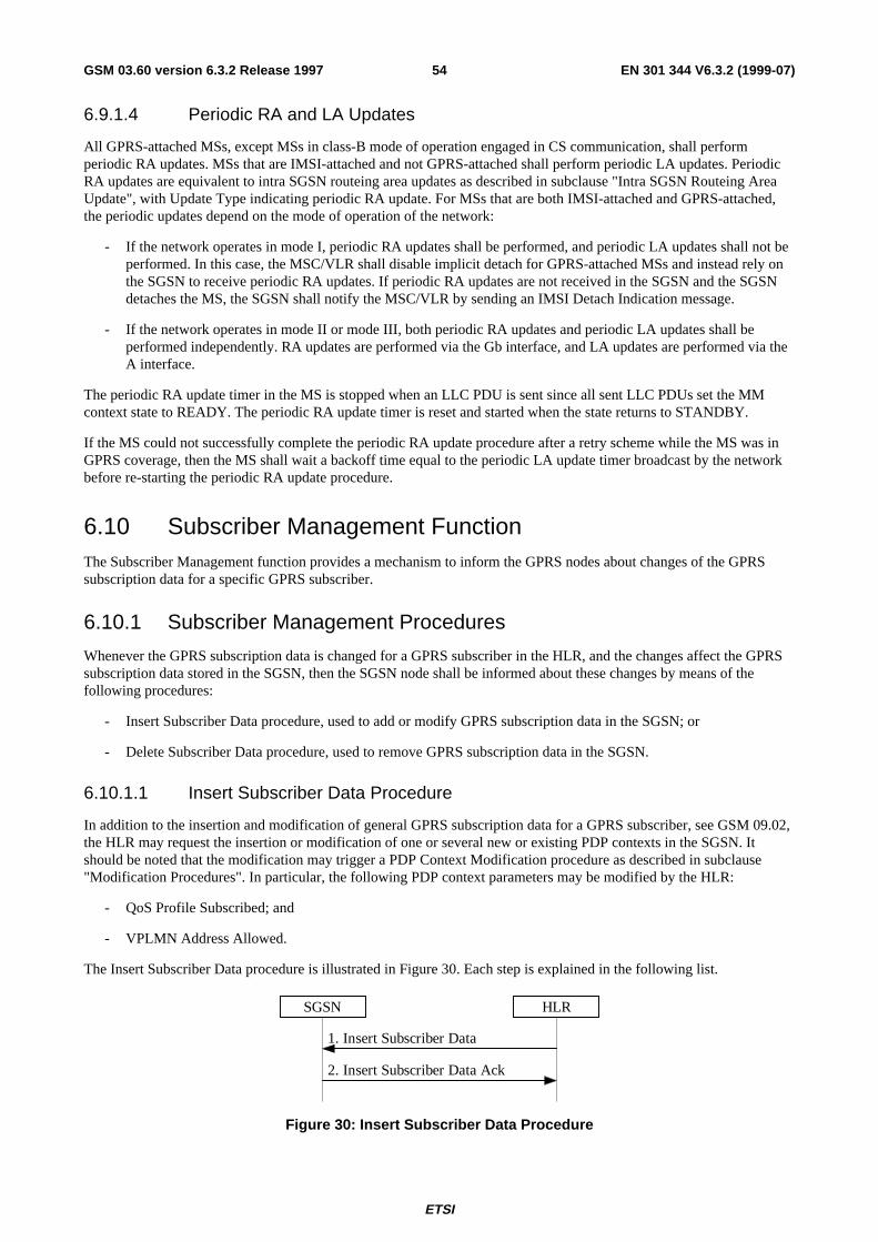
ETSI
EN 301 344 V6.3.2 (1999-07)54GSM 03.60 version 6.3.2 Release 1997
6.9.1.4 Periodic RA and LA Updates
All GPRS-attached MSs, except MSs in class-B mode of operation engaged in CS communication, shall performperiodic RA updates. MSs that are IMSI-attached and not GPRS-attached shall perform periodic LA updates. PeriodicRA updates are equivalent to intra SGSN routeing area updates as described in subclause "Intra SGSN Routeing AreaUpdate", with Update Type indicating periodic RA update. For MSs that are both IMSI-attached and GPRS-attached,the periodic updates depend on the mode of operation of the network:
- If the network operates in mode I, periodic RA updates shall be performed, and periodic LA updates shall not beperformed. In this case, the MSC/VLR shall disable implicit detach for GPRS-attached MSs and instead rely onthe SGSN to receive periodic RA updates. If periodic RA updates are not received in the SGSN and the SGSNdetaches the MS, the SGSN shall notify the MSC/VLR by sending an IMSI Detach Indication message.
- If the network operates in mode II or mode III, both periodic RA updates and periodic LA updates shall beperformed independently. RA updates are performed via the Gb interface, and LA updates are performed via theA interface.
The periodic RA update timer in the MS is stopped when an LLC PDU is sent since all sent LLC PDUs set the MMcontext state to READY. The periodic RA update timer is reset and started when the state returns to STANDBY.
If the MS could not successfully complete the periodic RA update procedure after a retry scheme while the MS was inGPRS coverage, then the MS shall wait a backoff time equal to the periodic LA update timer broadcast by the networkbefore re-starting the periodic RA update procedure.
6.10 Subscriber Management FunctionThe Subscriber Management function provides a mechanism to inform the GPRS nodes about changes of the GPRSsubscription data for a specific GPRS subscriber.
6.10.1 Subscriber Management Procedures
Whenever the GPRS subscription data is changed for a GPRS subscriber in the HLR, and the changes affect the GPRSsubscription data stored in the SGSN, then the SGSN node shall be informed about these changes by means of thefollowing procedures:
- Insert Subscriber Data procedure, used to add or modify GPRS subscription data in the SGSN; or
- Delete Subscriber Data procedure, used to remove GPRS subscription data in the SGSN.
6.10.1.1 Insert Subscriber Data Procedure
In addition to the insertion and modification of general GPRS subscription data for a GPRS subscriber, see GSM 09.02,the HLR may request the insertion or modification of one or several new or existing PDP contexts in the SGSN. Itshould be noted that the modification may trigger a PDP Context Modification procedure as described in subclause"Modification Procedures". In particular, the following PDP context parameters may be modified by the HLR:
- QoS Profile Subscribed; and
- VPLMN Address Allowed.
The Insert Subscriber Data procedure is illustrated in Figure 30. Each step is explained in the following list.
1. Insert Subscriber Data
2. Insert Subscriber Data Ack
SGSN HLR
Figure 30: Insert Subscriber Data Procedure
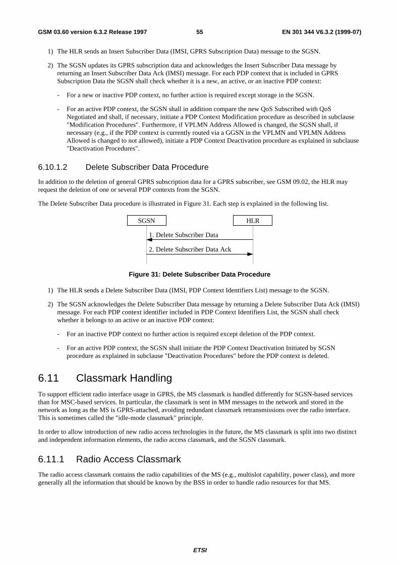
ETSI
EN 301 344 V6.3.2 (1999-07)55GSM 03.60 version 6.3.2 Release 1997
1) The HLR sends an Insert Subscriber Data (IMSI, GPRS Subscription Data) message to the SGSN.
2) The SGSN updates its GPRS subscription data and acknowledges the Insert Subscriber Data message byreturning an Insert Subscriber Data Ack (IMSI) message. For each PDP context that is included in GPRSSubscription Data the SGSN shall check whether it is a new, an active, or an inactive PDP context:
- For a new or inactive PDP context, no further action is required except storage in the SGSN.
- For an active PDP context, the SGSN shall in addition compare the new QoS Subscribed with QoSNegotiated and shall, if necessary, initiate a PDP Context Modification procedure as described in subclause"Modification Procedures". Furthermore, if VPLMN Address Allowed is changed, the SGSN shall, ifnecessary (e.g., if the PDP context is currently routed via a GGSN in the VPLMN and VPLMN AddressAllowed is changed to not allowed), initiate a PDP Context Deactivation procedure as explained in subclause"Deactivation Procedures".
6.10.1.2 Delete Subscriber Data Procedure
In addition to the deletion of general GPRS subscription data for a GPRS subscriber, see GSM 09.02, the HLR mayrequest the deletion of one or several PDP contexts from the SGSN.
The Delete Subscriber Data procedure is illustrated in Figure 31. Each step is explained in the following list.
1. Delete Subscriber Data
2. Delete Subscriber Data Ack
SGSN HLR
Figure 31: Delete Subscriber Data Procedure
1) The HLR sends a Delete Subscriber Data (IMSI, PDP Context Identifiers List) message to the SGSN.
2) The SGSN acknowledges the Delete Subscriber Data message by returning a Delete Subscriber Data Ack (IMSI)message. For each PDP context identifier included in PDP Context Identifiers List, the SGSN shall checkwhether it belongs to an active or an inactive PDP context:
- For an inactive PDP context no further action is required except deletion of the PDP context.
- For an active PDP context, the SGSN shall initiate the PDP Context Deactivation Initiated by SGSNprocedure as explained in subclause "Deactivation Procedures" before the PDP context is deleted.
6.11 Classmark HandlingTo support efficient radio interface usage in GPRS, the MS classmark is handled differently for SGSN-based servicesthan for MSC-based services. In particular, the classmark is sent in MM messages to the network and stored in thenetwork as long as the MS is GPRS-attached, avoiding redundant classmark retransmissions over the radio interface.This is sometimes called the "idle-mode classmark" principle.
In order to allow introduction of new radio access technologies in the future, the MS classmark is split into two distinctand independent information elements, the radio access classmark, and the SGSN classmark.
6.11.1 Radio Access Classmark
The radio access classmark contains the radio capabilities of the MS (e.g., multislot capability, power class), and moregenerally all the information that should be known by the BSS in order to handle radio resources for that MS.
ETSI
EN 301 344 V6.3.2 (1999-07)56GSM 03.60 version 6.3.2 Release 1997
The radio access classmark is a container for a multiplicity of radio access technology-dependent information, i.e.,within the radio access classmark there are independent sub-fields for various technologies such as GSM 900,GSM 1800, Satellite, UMTS, etc. The coding shall allow a BSS to extract only the sub-fields relevant to it withoutinterpreting the other sub-fields. This ensures that the radio classmark does not need to be interpreted by the NSS, andthe full radio classmark is always sent by the MS to the SGSN, and thereafter provided to the BSS irrespective of theactual BSS capabilities.
The SGSN shall provide the radio access classmark as an information element on the Gb interface. It is theresponsibility of the SGSN to provide the BSS with the most recent classmark received from the MS. The classmarkinformation element can be included in a downlink transfer request, or be sent in a specific message that updates theradio classmark information in the BSS. The BSS may at any time request the radio classmark for a given MS to betransmitted from the SGSN to the BSS.
A specific optimisation allows the BSS to receive a reduced radio access classmark at initial access directly from theMS. This enables the BSS not to wait for the full radio access classmark to be provided by the SGSN, and is thereforequicker for the initial MS-originated transmission. The reduced classmark can be carried is several RR messagesdepending on the access method, e.g., in the initial random access message, or in the first uplink radio block. Details areprovided in GSM 04.08 and GSM 04.60.
6.11.2 SGSN Classmark
The SGSN classmark contains non radio-related capabilities, e.g., the ciphering capability. The SGSN stores the SGSNclassmark which is used both locally by the SGSN and for transfer to the new SGSN at all types of inter SGSN RAupdate.
7 Network Management FunctionalityThe Network Management function provides mechanisms to support O&M functions related to GPRS.
8 Radio Resource Functionality
8.1 Cell Selection and ReselectionAn MS (in any mode of operation (A, B, or C)) cannot camp on more than one cell. This means that the cell selectionand reselection procedure should choose cells that support services the user has subscribed to.
If the MS is in idle mode, see GSM 03.22, then it shall behave as described below:
When the MS is in GPRS IDLE state and wishes to initiate the GPRS Attach procedure, the following applies:
- If the currently camped-on cell supports GPRS then no cell reselection is required.
- If the currently camped-on cell does not support GPRS, then reselection of a cell supporting GPRS is requiredbefore execution of the attach procedure.
If the MS is in GPRS STANDBY or READY state, cell selection and reselection procedures specific to GPRS shall beused, see GSM 03.22.
The cell reselection procedure used in READY state shall minimise the cell changes.
If the MS is in dedicated mode, see GSM 04.08, then the changes from one cell to another is performed according to thenetwork-controlled handover procedures.
There may be co-ordination of the idle and dedicated mode procedures used for circuit-switched services with theREADY state procedure for MSs that are both IMSI-attached and GPRS-attached.
ETSI
EN 301 344 V6.3.2 (1999-07)57GSM 03.60 version 6.3.2 Release 1997
8.2 Discontinuous ReceptionA GPRS MS may be able to choose if it wants to use discontinuous reception (DRX) or not. If using DRX, the MS shallalso be able to specify other DRX parameters that indicate the delay for the network to send a page request or a channelassignment to the MS (see GSM 03.64).
The DRX parameters shall be indicated by the MS in the attach procedure. The SGSN shall then in each page requestsend these parameters to the BSS that uses this information and the IMSI to calculate the correct paging group.
DRX usage is independent of the MM states IDLE, STANDBY and READY. As DRX can be used by a GPRS MS inREADY state, DRX has to be considered also when assigning a packet data channel for downlink transfer. The SGSNshall therefore indicate the DRX parameters for the MS in all packet transmission requests to the BSS.
A GPRS MS shall not apply DRX in READY state during the GPRS attach and routeing area update procedures.
8.3 Radio Resource ManagementGSM Radio Resource Management functions are defined in GSM 04.07 [12]. The radio interface layer 3 protocol isspecified in GSM 04.08.
8.3.1 Layer Functions
GPRS radio resource management procedures are required for the following functions:
- allocation and release of physical resources (i.e., timeslots) associated with a GPRS channel;
- monitoring GPRS channel utilisation to detect under-utilised or congested GPRS channels;
- initiating congestion control procedures; and
- distribution of GPRS channel configuration information for broadcasting to the MSs.
8.3.2 Model of Operation
8.3.2.1 Dynamic Allocation of Radio Resources
A cell may or may not support GPRS.
A cell supporting GPRS may have GPRS radio resources allocated at a given instance. If no GPRS radio resources areallocated, an MS can request allocation of such resources. MSs may then use these radio resources. The PLMN maydynamically increase, to a PLMN operator-defined maximum, or, decrease to an operator-defined minimum, the radioresources allocated.
The network broadcasts GPRS system information on the common control channels.
GSM radio resources are dynamically shared between GPRS and other GSM services.
8.4 Paging for GPRS Downlink TransferAn MS in STANDBY state is paged by the SGSN before a downlink transfer to that MS. The paging procedure shallmove the MM state to READY to allow the SGSN to forward downlink data to the radio resource. Therefore, any uplinkdata from the MS that moves the MM context at the SGSN to READY state is a valid response to paging.
The SGSN supervises the paging procedure with a timer. If the SGSN receives no response from the MS to the PagingRequest message, it shall repeat the paging. The repetition strategy is implementation dependent.
The MS shall accept pages also in READY state if no radio resource is assigned. This supports recovery frominconsistent MM states in MS and SGSN.
ETSI
EN 301 344 V6.3.2 (1999-07)58GSM 03.60 version 6.3.2 Release 1997
The Paging procedure is illustrated in Figure 32. Each step is explained in the following list.
5. Any LLC Frame
4. Any LLC Frame
3. GPRS Paging Request
2. Paging Request
1. PDP PDU
MS BSS SGSN
Figure 32: GPRS Paging Procedure
1) The SGSN receives a downlink PDP PDU for an MS in STANDBY state. Downlink signalling to a STANDBYstate MS initiates paging as well.
2) The SGSN sends a BSSGP Paging Request (IMSI, P-TMSI, Area, Channel Needed, QoS, DRX Parameters)message to the BSS serving the MS. IMSI is needed by the BSS in order to calculate the MS paging group.P-TMSI is the identifier by which the MS is paged. Area indicates the routeing area in which the MS is paged.Channel Needed indicates GPRS paging. QoS is the negotiated QoS for the PDP context that initiates the pagingprocedure, and indicates the priority of this Paging Request relative to other Paging Request messages buffered inthe BSS. DRX Parameters indicates whether the MS uses discontinuous reception or not. If the MS usesdiscontinuous reception, then DRX Parameters also indicate when the MS is in a non-sleep mode able to receivepaging requests.
3) The BSS pages the MS with one Paging Request (P-TMSI, Channel Needed) message in each cell belonging tothe addressed routeing area. This is described in GSM 03.64.
4) Upon receipt of a GPRS Paging Request message, the MS shall respond with either any single valid LLC frame(e.g., a Receive Ready or Information frame) that implicitly is interpreted as a page response message by theSGSN. When responding, the MS changes MM state to READY. The response is preceded by the PacketChannel Request and Packet Immediate Assignment procedures as described in GSM 03.64.
5) Upon reception of the LLC frame, the BSS adds the Cell Global Identity including the RAC and LAC of the celland sends the LLC frame to the SGSN. The SGSN shall then consider the LLC frame to be an implicit pagingresponse message and stop the paging response timer.
9 Packet Routeing and Transfer Functionality
9.1 Definition of Packet Data Protocol StatesA PTP GPRS subscription contains the subscription of one or more PDP addresses. Each PDP address is described byan individual PDP context in the MS, the SGSN, and the GGSN. Every PDP context exists independently in one of twoPDP states. The PDP state indicates whether the PDP address is activated for data transfer or not. Activation anddeactivation are described in subclause "PDP Context Activation, Modification, and Deactivation Functions". All PDPcontexts of a subscriber are associated with the same MM context for the IMSI of that subscriber.
9.1.1 INACTIVE State
The INACTIVE state characterises the data service for a certain PDP address of the subscriber as not activated. ThePDP context contains no routeing or mapping information to process PDUs related to that PDP address. No data can betransferred. A changing location of a subscriber causes no update for the PDP context in INACTIVE state even if thesubscriber is attached to the GPRS MM.
ETSI
EN 301 344 V6.3.2 (1999-07)59GSM 03.60 version 6.3.2 Release 1997
Mobile-terminated PTP packets received in INACTIVE state by the GGSN may initiate the Network-Requested PDPContext Activation procedure if the GGSN is allowed to initiate the activation of the PDP context for that PDP address.Otherwise, mobile-terminated PTP packets received in INACTIVE state invoke error procedures in the GGSN relevantto the external network protocol, for example, an IP packet is discarded and an ICMP [41] packet (error notification) isreturned to the source of the received packet. Other error procedures may be introduced on the application level, but thisis outside the scope of the present document.
The MS initiates the movement from INACTIVE to ACTIVE state by initiating the PDP Context Activation procedure.
9.1.2 ACTIVE State
In ACTIVE state, the PDP context for the PDP address in use is activated in MS, SGSN and GGSN. The PDP contextcontains mapping and routeing information for transferring PDUs for that particular PDP address between MS andGGSN. The PDP state ACTIVE is permitted only when the mobility management state of the subscriber is STANDBYor READY.
An active PDP context for an MS is moved to INACTIVE state when the deactivation procedure is initiated.
All active PDP contexts for an MS are moved to INACTIVE state when the MM state changes to IDLE.
Deactivate PDP Contextor
MM state change to IDLE
Activate PDPContext
INACTIVE
ACTIVE
Figure 33: Functional PDP State Model
9.2 PDP Context Activation, Modification, and DeactivationFunctions
These functions are only meaningful at the NSS level and in the MS, and do not directly involve the BSS. An MS inSTANDBY or READY state can initiate these functions at any time to activate or deactivate a PDP context in the MS,the SGSN, and the GGSN. A GGSN may request the activation of a PDP context to a GPRS-attached subscriber. AGGSN may initiate the deactivation of a PDP context.
Upon receiving an Activate PDP Context Request message, the SGSN shall initiate procedures to set up PDP contexts.
Upon receiving a Deactivate PDP Context Request message, the SGSN shall initiate procedures to deactivate PDPcontexts. If a logical name is stored in the PDP context "GGSN Address" field and if the SGSN needs to use this field,then the SGSN shall convert this logical name to an IP address upon PDP context activation. The SGSN shall store theconverted IP address in the "GGSN Address in Use" field. If an IP address is stored in the "GGSN Address" field, thenthe same IP address shall be stored in "GGSN Address in Use".
An MS does not have to receive the (De-)Activate PDP Context Accept message before issuing another (De-)ActivatePDP Context Request. However, only one request can be outstanding for every NSAPI.

ETSI
EN 301 344 V6.3.2 (1999-07)60GSM 03.60 version 6.3.2 Release 1997
9.2.1 Static and Dynamic PDP Addresses
PDP addresses can be allocated to an MS in three different ways:
- the HPLMN operator assigns a PDP address permanently to the MS (static PDP address);
- the HPLMN operator assigns a PDP address to the MS when a PDP context is activated (dynamic HPLMN PDPaddress); or
- the VPLMN operator assigns a PDP address to the MS when a PDP context is activated (dynamic VPLMN PDPaddress).
It is the HPLMN operator that defines in the subscription whether a dynamic HPLMN or VPLMN PDP address can beused.
For every IMSI, zero, one, or more dynamic PDP address per PDP type can be assigned. For every IMSI, zero, one, ormore static PDP addresses per PDP type can be subscribed to.
When dynamic addressing is used, it is the responsibility of the GGSN to allocate and release the dynamic PDP address.
Only static PDP addressing is applicable in the network-requested PDP context activation case.
9.2.2 Activation Procedures
9.2.2.1 PDP Context Activation Procedure
The PDP Context Activation procedure is illustrated in Figure 34. Each step is explained in the following list.
GGSN
4. Activate PDP Context Accept
3. Create PDP Context Response
3. Create PDP Context Request
1. Activate PDP Context Request
SGSNMS
2. Security Functions
Figure 34: PDP Context Activation Procedure
1) The MS sends an Activate PDP Context Request (NSAPI, TI, PDP Type, PDP Address, Access Point Name,QoS Requested, PDP Configuration Options) message to the SGSN. The MS shall use PDP Address to indicatewhether it requires the use of a static PDP address or whether it requires the use of a dynamic PDP address. TheMS shall leave PDP Address empty to request a dynamic PDP address. The MS may use Access Point Name toselect a reference point to a certain external network. Access Point Name is a logical name referring to theexternal packet data network that the subscriber wishes to connect to. QoS Requested indicates the desired QoSprofile. PDP Configuration Options may be used to request optional PDP parameters from the GGSN (seeGSM 09.60). PDP Configuration Options is sent transparently through the SGSN.
2) Security functions may be executed. These procedures are defined in subclause "Security Function".
3) The SGSN validates the Activate PDP Context Request using PDP Type (optional), PDP Address (optional), andAccess Point Name (optional) provided by the MS and the PDP context subscription records. The validationcriteria, the APN selection criteria, and the mapping from APN to a GGSN are described in annex A.
If no GGSN address can be derived or if the SGSN has determined that the Activate PDP Context Request is notvalid according to the rules described in annex A, then the SGSN rejects the PDP context activation request.
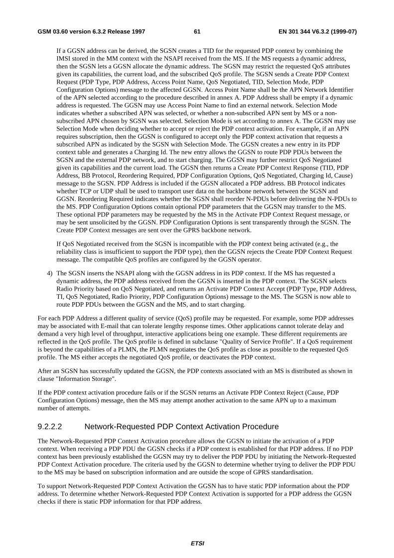
ETSI
EN 301 344 V6.3.2 (1999-07)61GSM 03.60 version 6.3.2 Release 1997
If a GGSN address can be derived, the SGSN creates a TID for the requested PDP context by combining theIMSI stored in the MM context with the NSAPI received from the MS. If the MS requests a dynamic address,then the SGSN lets a GGSN allocate the dynamic address. The SGSN may restrict the requested QoS attributesgiven its capabilities, the current load, and the subscribed QoS profile. The SGSN sends a Create PDP ContextRequest (PDP Type, PDP Address, Access Point Name, QoS Negotiated, TID, Selection Mode, PDPConfiguration Options) message to the affected GGSN. Access Point Name shall be the APN Network Identifierof the APN selected according to the procedure described in annex A. PDP Address shall be empty if a dynamicaddress is requested. The GGSN may use Access Point Name to find an external network. Selection Modeindicates whether a subscribed APN was selected, or whether a non-subscribed APN sent by MS or a non-subscribed APN chosen by SGSN was selected. Selection Mode is set according to annex A. The GGSN may useSelection Mode when deciding whether to accept or reject the PDP context activation. For example, if an APNrequires subscription, then the GGSN is configured to accept only the PDP context activation that requests asubscribed APN as indicated by the SGSN with Selection Mode. The GGSN creates a new entry in its PDPcontext table and generates a Charging Id. The new entry allows the GGSN to route PDP PDUs between theSGSN and the external PDP network, and to start charging. The GGSN may further restrict QoS Negotiatedgiven its capabilities and the current load. The GGSN then returns a Create PDP Context Response (TID, PDPAddress, BB Protocol, Reordering Required, PDP Configuration Options, QoS Negotiated, Charging Id, Cause)message to the SGSN. PDP Address is included if the GGSN allocated a PDP address. BB Protocol indicateswhether TCP or UDP shall be used to transport user data on the backbone network between the SGSN andGGSN. Reordering Required indicates whether the SGSN shall reorder N-PDUs before delivering the N-PDUs tothe MS. PDP Configuration Options contain optional PDP parameters that the GGSN may transfer to the MS.These optional PDP parameters may be requested by the MS in the Activate PDP Context Request message, ormay be sent unsolicited by the GGSN. PDP Configuration Options is sent transparently through the SGSN. TheCreate PDP Context messages are sent over the GPRS backbone network.
If QoS Negotiated received from the SGSN is incompatible with the PDP context being activated (e.g., thereliability class is insufficient to support the PDP type), then the GGSN rejects the Create PDP Context Requestmessage. The compatible QoS profiles are configured by the GGSN operator.
4) The SGSN inserts the NSAPI along with the GGSN address in its PDP context. If the MS has requested adynamic address, the PDP address received from the GGSN is inserted in the PDP context. The SGSN selectsRadio Priority based on QoS Negotiated, and returns an Activate PDP Context Accept (PDP Type, PDP Address,TI, QoS Negotiated, Radio Priority, PDP Configuration Options) message to the MS. The SGSN is now able toroute PDP PDUs between the GGSN and the MS, and to start charging.
For each PDP Address a different quality of service (QoS) profile may be requested. For example, some PDP addressesmay be associated with E-mail that can tolerate lengthy response times. Other applications cannot tolerate delay anddemand a very high level of throughput, interactive applications being one example. These different requirements arereflected in the QoS profile. The QoS profile is defined in subclause "Quality of Service Profile". If a QoS requirementis beyond the capabilities of a PLMN, the PLMN negotiates the QoS profile as close as possible to the requested QoSprofile. The MS either accepts the negotiated QoS profile, or deactivates the PDP context.
After an SGSN has successfully updated the GGSN, the PDP contexts associated with an MS is distributed as shown inclause "Information Storage".
If the PDP context activation procedure fails or if the SGSN returns an Activate PDP Context Reject (Cause, PDPConfiguration Options) message, then the MS may attempt another activation to the same APN up to a maximumnumber of attempts.
9.2.2.2 Network-Requested PDP Context Activation Procedure
The Network-Requested PDP Context Activation procedure allows the GGSN to initiate the activation of a PDPcontext. When receiving a PDP PDU the GGSN checks if a PDP context is established for that PDP address. If no PDPcontext has been previously established the GGSN may try to deliver the PDP PDU by initiating the Network-RequestedPDP Context Activation procedure. The criteria used by the GGSN to determine whether trying to deliver the PDP PDUto the MS may be based on subscription information and are outside the scope of GPRS standardisation.
To support Network-Requested PDP Context Activation the GGSN has to have static PDP information about the PDPaddress. To determine whether Network-Requested PDP Context Activation is supported for a PDP address the GGSNchecks if there is static PDP information for that PDP address.
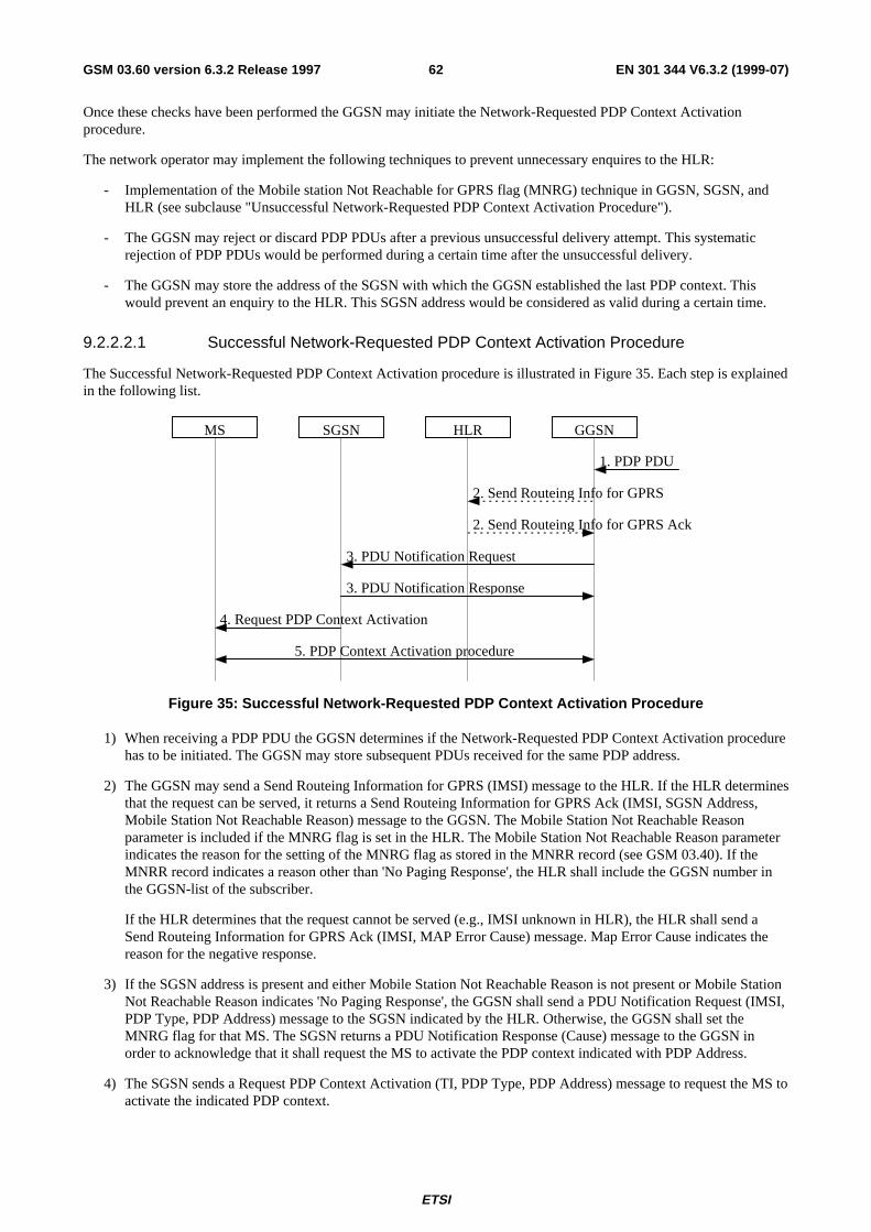
ETSI
EN 301 344 V6.3.2 (1999-07)62GSM 03.60 version 6.3.2 Release 1997
Once these checks have been performed the GGSN may initiate the Network-Requested PDP Context Activationprocedure.
The network operator may implement the following techniques to prevent unnecessary enquires to the HLR:
- Implementation of the Mobile station Not Reachable for GPRS flag (MNRG) technique in GGSN, SGSN, andHLR (see subclause "Unsuccessful Network-Requested PDP Context Activation Procedure").
- The GGSN may reject or discard PDP PDUs after a previous unsuccessful delivery attempt. This systematicrejection of PDP PDUs would be performed during a certain time after the unsuccessful delivery.
- The GGSN may store the address of the SGSN with which the GGSN established the last PDP context. Thiswould prevent an enquiry to the HLR. This SGSN address would be considered as valid during a certain time.
9.2.2.2.1 Successful Network-Requested PDP Context Activation Procedure
The Successful Network-Requested PDP Context Activation procedure is illustrated in Figure 35. Each step is explainedin the following list.
MS SGSN GGSN
3. PDU Notification Request
HLR
1. PDP PDU
2. Send Routeing Info for GPRS
2. Send Routeing Info for GPRS Ack
4. Request PDP Context Activation
5. PDP Context Activation procedure
3. PDU Notification Response
Figure 35: Successful Network-Requested PDP Context Activation Procedure
1) When receiving a PDP PDU the GGSN determines if the Network-Requested PDP Context Activation procedurehas to be initiated. The GGSN may store subsequent PDUs received for the same PDP address.
2) The GGSN may send a Send Routeing Information for GPRS (IMSI) message to the HLR. If the HLR determinesthat the request can be served, it returns a Send Routeing Information for GPRS Ack (IMSI, SGSN Address,Mobile Station Not Reachable Reason) message to the GGSN. The Mobile Station Not Reachable Reasonparameter is included if the MNRG flag is set in the HLR. The Mobile Station Not Reachable Reason parameterindicates the reason for the setting of the MNRG flag as stored in the MNRR record (see GSM 03.40). If theMNRR record indicates a reason other than 'No Paging Response', the HLR shall include the GGSN number inthe GGSN-list of the subscriber.
If the HLR determines that the request cannot be served (e.g., IMSI unknown in HLR), the HLR shall send aSend Routeing Information for GPRS Ack (IMSI, MAP Error Cause) message. Map Error Cause indicates thereason for the negative response.
3) If the SGSN address is present and either Mobile Station Not Reachable Reason is not present or Mobile StationNot Reachable Reason indicates 'No Paging Response', the GGSN shall send a PDU Notification Request (IMSI,PDP Type, PDP Address) message to the SGSN indicated by the HLR. Otherwise, the GGSN shall set theMNRG flag for that MS. The SGSN returns a PDU Notification Response (Cause) message to the GGSN inorder to acknowledge that it shall request the MS to activate the PDP context indicated with PDP Address.
4) The SGSN sends a Request PDP Context Activation (TI, PDP Type, PDP Address) message to request the MS toactivate the indicated PDP context.
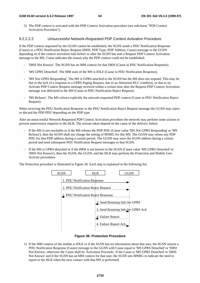
ETSI
EN 301 344 V6.3.2 (1999-07)63GSM 03.60 version 6.3.2 Release 1997
5) The PDP context is activated with the PDP Context Activation procedure (see subclause "PDP ContextActivation Procedure").
9.2.2.2.2 Unsuccessful Network-Requested PDP Context Activation Procedure
If the PDP context requested by the GGSN cannot be established, the SGSN sends a PDU Notification Response(Cause) or a PDU Notification Reject Request (IMSI, PDP Type, PDP Address, Cause) message to the GGSNdepending on if the context activation fails before or after the SGSN has sent a Request PDP Context Activationmessage to the MS. Cause indicates the reason why the PDP context could not be established:
- 'IMSI Not Known'. The SGSN has no MM context for that IMSI (Cause in PDU Notification Response).
- 'MS GPRS Detached'. The MM state of the MS is IDLE (Cause in PDU Notification Response).
- 'MS Not GPRS Responding'. The MS is GPRS-attached to the SGSN but the MS does not respond. This may bedue to the lack of a response to a GPRS Paging Request, due to an Abnormal RLC condition, or due to noActivate PDP Context Request message received within a certain time after the Request PDP Context Activationmessage was delivered to the MS (Cause in PDU Notification Reject Request).
- 'MS Refuses'. The MS refuses explicitly the network-requested PDP context (Cause in PDU Notification RejectRequest).
When receiving the PDU Notification Response or the PDU Notification Reject Request message the GGSN may rejector discard the PDP PDU depending on the PDP type.
After an unsuccessful Network-Requested PDP Context Activation procedure the network may perform some actions toprevent unnecessary enquires to the HLR. The actions taken depend on the cause of the delivery failure.
- If the MS is not reachable or if the MS refuses the PDP PDU (Cause value 'MS Not GPRS Responding' or 'MSRefuses'), then the SGSN shall not change the setting of MNRG for this MS. The GGSN may refuse any PDPPDU for that PDP address during a certain period. The GGSN may store the SGSN address during a certainperiod and send subsequent PDU Notification Request messages to that SGSN.
- If the MS is GPRS-detached or if the IMSI is not known in the SGSN (Cause value 'MS GPRS Detached' or'IMSI Not Known'), then the SGSN, the GGSN, and the HLR may perform the Protection and Mobile UserActivity procedures.
The Protection procedure is illustrated in Figure 36. Each step is explained in the following list.
SGSN HLR GGSN
1. PDU Notification Response
3. Send Routeing Info for GPRS
3. Send Routeing Info for GPRS Ack
4. Failure Report
4. Failure Report Ack
2. PDU Notification Reject Response
2. PDU Notification Reject Request
Figure 36: Protection Procedure
1) If the MM context of the mobile is IDLE or if the SGSN has no information about that user, the SGSN returns aPDU Notification Response (Cause) message to the GGSN with Cause equal to 'MS GPRS Detached' or 'IMSINot Known', otherwise the Cause shall be 'Activation Proceeds'. If the Cause is 'MS GPRS Detached' or 'IMSINot Known' and if the SGSN has an MM context for that user, the SGSN sets MNRG to indicate the need toreport to the HLR when the next contact with that MS is performed.
ETSI
EN 301 344 V6.3.2 (1999-07)64GSM 03.60 version 6.3.2 Release 1997
2) If the MS does not respond or refuses the activation request, the SGSN sends a PDU Notification Reject Request(IMSI, PDP Type, PDP Address, Cause) message to the GGSN with Cause equal to 'MS Not GPRS Responding'or 'MS Refuses'. The GGSN returns a PDU Notification Reject Response message to the SGSN.
3) If Cause equals 'IMSI Not Known' the GGSN may send a Send Routeing Information for GPRS (IMSI) messageto the HLR. The HLR returns a Send Routeing Information for GPRS Ack (IMSI, SGSN Address, Cause)message to the GGSN indicating the address of the SGSN that currently serves the MS. If SGSN Address isdifferent from the one previously stored by the GGSN, then steps 3, 4, and 5 in Figure 35 are followed.
4) If SGSN Address is the same as the one previously stored in the GGSN, or if the Cause value returned in step 1equals 'MS GPRS Detached', then the GGSN sets MNRG for that PDP address and sends a Failure Report (IMSI,GGSN Number, GGSN Address) message to the HLR to request MNRG to be set in the HLR. The HLR sets (ifnot already set) MNRG for the IMSI and adds GGSN Number and GGSN Address to the list of GGSNs to reportto when activity from that IMSI is detected. GGSN Number is either the number of the GGSN, or, if a protocol-converting GSN is used as an intermediate node, the number of the protocol-converting GSN. GGSN Address isan optional parameter that shall be included if a protocol-converting GSN is used.
The Mobile User Activity procedure is illustrated in Figure 37. Each step is explained in the following list.
3. Note MS GPRS Present
SGSN HLR GGSN
1. Attach Request
2a. Ready for SM
2b. Update Location
MS
Figure 37: Mobile User Activity Procedure
1) The SGSN receives an indication that an MS is reachable, e.g., an Attach Request message from the MS.
2a) If the SGSN contains an MM context of the MS and MNRG for that MS is set, the SGSN shall send a Ready forSM (IMSI, MS Reachable) message to the HLR and clears MNRG for that MS.
2b)If the SGSN does not keep the MM context of the MS, the SGSN shall send an Update Location message (seesubclause "Attach Function") to the HLR.
3) When the HLR receives the Ready for SM message or the Update Location message for an MS that has MNRGset, it clears MNRG for that MS and sends a Note MS GPRS Present (IMSI, SGSN Address) message to all theGGSNs in the list of the subscriber. (The Ready for SM message also triggers the SMS alert procedure asdescribed in subclause "Unsuccessful Mobile-terminated SMS Transfer".) SGSN Address contains the address ofthe SGSN that currently serves the MS. Upon reception of Note MS Present, each GGSN shall clear MNRG.
9.2.2.3 Anonymous Access PDP Context Activation Procedure
The MS can anonymously initiate PDP Context Activation in IDLE, STANDBY, and READY states. An existing MMcontext in the SGSN is neither required nor used in this case. Only dynamic PDP addressing is applicable.
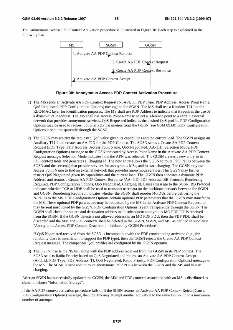
ETSI
EN 301 344 V6.3.2 (1999-07)65GSM 03.60 version 6.3.2 Release 1997
The Anonymous Access PDP Context Activation procedure is illustrated in Figure 38. Each step is explained in thefollowing list.
3. Activate AA PDP Context Accept
2. Create AA PDP Context Response
2. Create AA PDP Context Request
1. Activate AA PDP Context Request
SGSN GGSNMS
Figure 38: Anonymous Access PDP Context Activation Procedure
1) The MS sends an Activate AA PDP Context Request (NSAPI, TI, PDP Type, PDP Address, Access Point Name,QoS Requested, PDP Configuration Options) message to the SGSN. The MS shall use a Random TLLI at theRLC/MAC layer for identification purposes. The MS shall use PDP Address to indicate that it requires the use ofa dynamic PDP address. The MS shall use Access Point Name to select a reference point to a certain externalnetwork that provides anonymous services. QoS Requested indicates the desired QoS profile. PDP ConfigurationOptions may be used to request optional PDP parameters from the GGSN (see GSM 09.60). PDP ConfigurationOptions is sent transparently through the SGSN.
2) The SGSN may restrict the requested QoS value given its capabilities and the current load. The SGSN assigns anAuxiliary TLLI and creates an AA-TID for the PDP-Context. The SGSN sends a Create AA PDP ContextRequest (PDP Type, PDP Address, Access Point Name, QoS Negotiated, AA-TID, Selection Mode, PDPConfiguration Options) message to the GGSN indicated by Access Point Name in the Activate AA PDP ContextRequest message. Selection Mode indicates how the APN was selected. The GGSN creates a new entry in itsPDP context table and generates a Charging Id. The new entry allows the GGSN to route PDP PDUs between theSGSN and the server(s) that provide services for anonymous MSs, and to start charging. The GGSN may useAccess Point Name to find an external network that provides anonymous services. The GGSN may furtherrestrict QoS Negotiated given its capabilities and the current load. The GGSN then allocates a dynamic PDPAddress and returns a Create AA PDP Context Response (AA-TID, PDP Address, BB Protocol, ReorderingRequired, PDP Configuration Options, QoS Negotiated, Charging Id, Cause) message to the SGSN. BB Protocolindicates whether TCP or UDP shall be used to transport user data on the backbone network between the SGSNand GGSN. Reordering Required indicates whether the SGSN shall reorder N-PDUs before delivering theN-PDUs to the MS. PDP Configuration Options contain optional PDP parameters that the GGSN may transfer tothe MS. These optional PDP parameters may be requested by the MS in the Activate PDP Context Request, ormay be sent unsolicited by the GGSN. PDP Configuration Options is sent transparently through the SGSN. TheGGSN shall check the source and destination address in all subsequent anonymous MO PDP PDUs receivedfrom the SGSN. If the GGSN detects a not allowed address in an MO PDP PDU, then the PDP PDU shall bediscarded and the MM and PDP contexts shall be deleted in the GGSN, SGSN, and MS, as defined in subclause"Anonymous Access PDP Context Deactivation Initiated by GGSN Procedure".
If QoS Negotiated received from the SGSN is incompatible with the PDP context being activated (e.g., thereliability class is insufficient to support the PDP type), then the GGSN rejects the Create AA PDP ContextRequest message. The compatible QoS profiles are configured by the GGSN operator.
3) The SGSN inserts the NSAPI along with the PDP address received from the GGSN in its PDP context. TheSGSN selects Radio Priority based on QoS Negotiated and returns an Activate AA PDP Context Accept(A-TLLI, PDP Type, PDP Address, TI, QoS Negotiated, Radio Priority, PDP Configuration Options) message tothe MS. The SGSN is now able to route anonymous PDP PDUs between the GGSN and the MS and to startcharging.
After an SGSN has successfully updated the GGSN, the MM and PDP contexts associated with an MS is distributed asshown in clause "Information Storage".
If the AA PDP context activation procedure fails or if the SGSN returns an Activate AA PDP Context Reject (Cause,PDP Configuration Options) message, then the MS may attempt another activation to the same GGSN up to a maximumnumber of attempts.
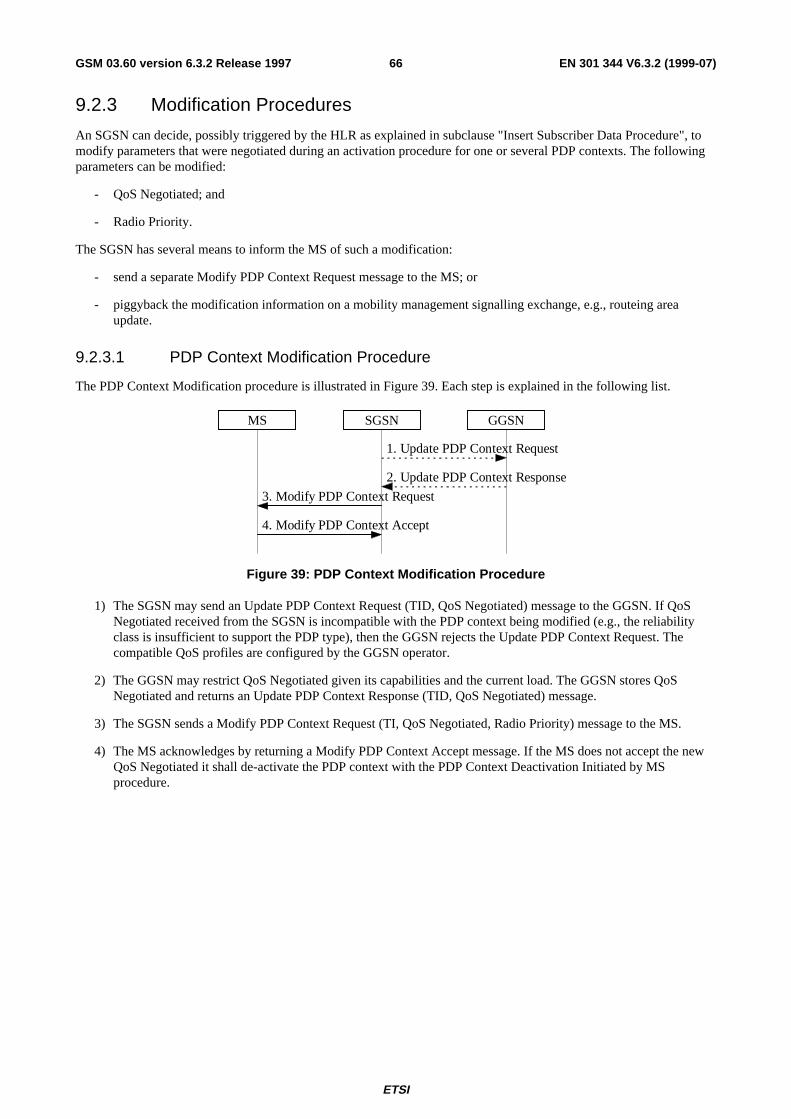
ETSI
EN 301 344 V6.3.2 (1999-07)66GSM 03.60 version 6.3.2 Release 1997
9.2.3 Modification Procedures
An SGSN can decide, possibly triggered by the HLR as explained in subclause "Insert Subscriber Data Procedure", tomodify parameters that were negotiated during an activation procedure for one or several PDP contexts. The followingparameters can be modified:
- QoS Negotiated; and
- Radio Priority.
The SGSN has several means to inform the MS of such a modification:
- send a separate Modify PDP Context Request message to the MS; or
- piggyback the modification information on a mobility management signalling exchange, e.g., routeing areaupdate.
9.2.3.1 PDP Context Modification Procedure
The PDP Context Modification procedure is illustrated in Figure 39. Each step is explained in the following list.
4. Modify PDP Context Accept
2. Update PDP Context Response
1. Update PDP Context Request
3. Modify PDP Context Request
SGSN GGSNMS
Figure 39: PDP Context Modification Procedure
1) The SGSN may send an Update PDP Context Request (TID, QoS Negotiated) message to the GGSN. If QoSNegotiated received from the SGSN is incompatible with the PDP context being modified (e.g., the reliabilityclass is insufficient to support the PDP type), then the GGSN rejects the Update PDP Context Request. Thecompatible QoS profiles are configured by the GGSN operator.
2) The GGSN may restrict QoS Negotiated given its capabilities and the current load. The GGSN stores QoSNegotiated and returns an Update PDP Context Response (TID, QoS Negotiated) message.
3) The SGSN sends a Modify PDP Context Request (TI, QoS Negotiated, Radio Priority) message to the MS.
4) The MS acknowledges by returning a Modify PDP Context Accept message. If the MS does not accept the newQoS Negotiated it shall de-activate the PDP context with the PDP Context Deactivation Initiated by MSprocedure.
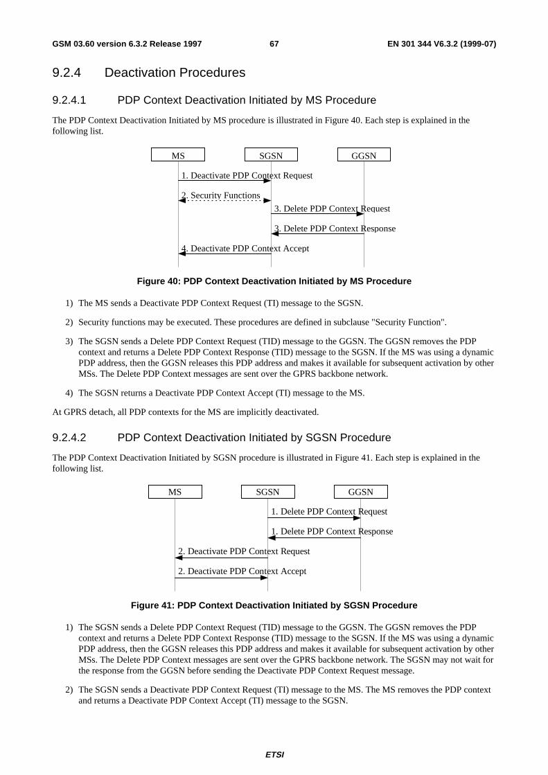
ETSI
EN 301 344 V6.3.2 (1999-07)67GSM 03.60 version 6.3.2 Release 1997
9.2.4 Deactivation Procedures
9.2.4.1 PDP Context Deactivation Initiated by MS Procedure
The PDP Context Deactivation Initiated by MS procedure is illustrated in Figure 40. Each step is explained in thefollowing list.
GGSN
4. Deactivate PDP Context Accept
3. Delete PDP Context Response
3. Delete PDP Context Request
1. Deactivate PDP Context Request
SGSNMS
2. Security Functions
Figure 40: PDP Context Deactivation Initiated by MS Procedure
1) The MS sends a Deactivate PDP Context Request (TI) message to the SGSN.
2) Security functions may be executed. These procedures are defined in subclause "Security Function".
3) The SGSN sends a Delete PDP Context Request (TID) message to the GGSN. The GGSN removes the PDPcontext and returns a Delete PDP Context Response (TID) message to the SGSN. If the MS was using a dynamicPDP address, then the GGSN releases this PDP address and makes it available for subsequent activation by otherMSs. The Delete PDP Context messages are sent over the GPRS backbone network.
4) The SGSN returns a Deactivate PDP Context Accept (TI) message to the MS.
At GPRS detach, all PDP contexts for the MS are implicitly deactivated.
9.2.4.2 PDP Context Deactivation Initiated by SGSN Procedure
The PDP Context Deactivation Initiated by SGSN procedure is illustrated in Figure 41. Each step is explained in thefollowing list.
GGSN
1. Delete PDP Context Request
SGSN
1. Delete PDP Context Response
2. Deactivate PDP Context Accept
2. Deactivate PDP Context Request
MS
Figure 41: PDP Context Deactivation Initiated by SGSN Procedure
1) The SGSN sends a Delete PDP Context Request (TID) message to the GGSN. The GGSN removes the PDPcontext and returns a Delete PDP Context Response (TID) message to the SGSN. If the MS was using a dynamicPDP address, then the GGSN releases this PDP address and makes it available for subsequent activation by otherMSs. The Delete PDP Context messages are sent over the GPRS backbone network. The SGSN may not wait forthe response from the GGSN before sending the Deactivate PDP Context Request message.
2) The SGSN sends a Deactivate PDP Context Request (TI) message to the MS. The MS removes the PDP contextand returns a Deactivate PDP Context Accept (TI) message to the SGSN.
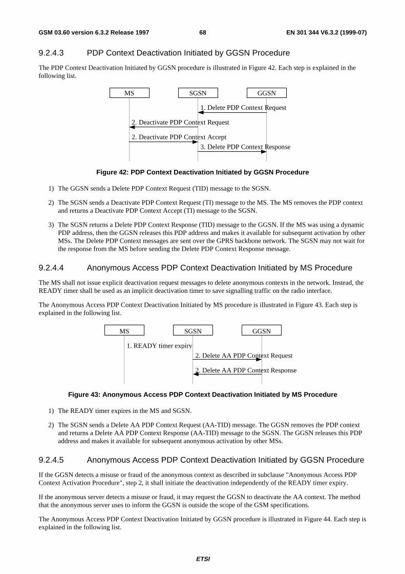
ETSI
EN 301 344 V6.3.2 (1999-07)68GSM 03.60 version 6.3.2 Release 1997
9.2.4.3 PDP Context Deactivation Initiated by GGSN Procedure
The PDP Context Deactivation Initiated by GGSN procedure is illustrated in Figure 42. Each step is explained in thefollowing list.
GGSN
1. Delete PDP Context Request
SGSN
3. Delete PDP Context Response
2. Deactivate PDP Context Accept
2. Deactivate PDP Context Request
MS
Figure 42: PDP Context Deactivation Initiated by GGSN Procedure
1) The GGSN sends a Delete PDP Context Request (TID) message to the SGSN.
2) The SGSN sends a Deactivate PDP Context Request (TI) message to the MS. The MS removes the PDP contextand returns a Deactivate PDP Context Accept (TI) message to the SGSN.
3) The SGSN returns a Delete PDP Context Response (TID) message to the GGSN. If the MS was using a dynamicPDP address, then the GGSN releases this PDP address and makes it available for subsequent activation by otherMSs. The Delete PDP Context messages are sent over the GPRS backbone network. The SGSN may not wait forthe response from the MS before sending the Delete PDP Context Response message.
9.2.4.4 Anonymous Access PDP Context Deactivation Initiated by MS Procedure
The MS shall not issue explicit deactivation request messages to delete anonymous contexts in the network. Instead, theREADY timer shall be used as an implicit deactivation timer to save signalling traffic on the radio interface.
The Anonymous Access PDP Context Deactivation Initiated by MS procedure is illustrated in Figure 43. Each step isexplained in the following list.
2. Delete AA PDP Context Response
2. Delete AA PDP Context Request
1. READY timer expiry
MS SGSN GGSN
Figure 43: Anonymous Access PDP Context Deactivation Initiated by MS Procedure
1) The READY timer expires in the MS and SGSN.
2) The SGSN sends a Delete AA PDP Context Request (AA-TID) message. The GGSN removes the PDP contextand returns a Delete AA PDP Context Response (AA-TID) message to the SGSN. The GGSN releases this PDPaddress and makes it available for subsequent anonymous activation by other MSs.
9.2.4.5 Anonymous Access PDP Context Deactivation Initiated by GGSN Procedure
If the GGSN detects a misuse or fraud of the anonymous context as described in subclause "Anonymous Access PDPContext Activation Procedure", step 2, it shall initiate the deactivation independently of the READY timer expiry.
If the anonymous server detects a misuse or fraud, it may request the GGSN to deactivate the AA context. The methodthat the anonymous server uses to inform the GGSN is outside the scope of the GSM specifications.
The Anonymous Access PDP Context Deactivation Initiated by GGSN procedure is illustrated in Figure 44. Each step isexplained in the following list.
ETSI
EN 301 344 V6.3.2 (1999-07)69GSM 03.60 version 6.3.2 Release 1997
GGSN
1. Delete AA PDP Context Request
SGSN
4. Delete AA PDP Context Response
3. Deactivate AA PDP Context Accept
3. Deactivate AA PDP Context Request
MS
2. Identity Response
2. Identity Request
Figure 44: Anonymous Access PDP Context Deactivation Initiated by GGSN Procedure
1) The GGSN sends a Delete AA PDP Context Request (AA-TID) message to the SGSN.
2) The SGSN may send an Identity Request (Identity Type = IMSI or IMEI) message to the MS. The MS shallrespond with an Identity Response (IMSI or IMEI) message.
3) The SGSN sends a Deactivate AA PDP Context Request (TI) message to the MS. The MS removes the PDPcontext and returns a Deactivate AA PDP Context Accept (TI) message to the SGSN.
4) The SGSN returns a Delete AA PDP Context Response (AA-TID) message to the GGSN. The GGSN releasesthis PDP address and makes it available for subsequent activation by other MSs. The Delete AA PDP Contextmessages are sent over the GPRS backbone network. The SGSN may not wait for the accept from the MS beforesending the Delete AA PDP Context Response message.
9.3 Packet Routeing and Transfer FunctionThe packet routeing and transfer function:
- routes and transfers packets between a mobile TE and an external network, i.e., between reference point R andreference point Gi;
- routes and transfers packets between mobile TE and other GPRS PLMN, i.e., between reference point R andreference point Gi via interface Gp; and
- routes and transfers packets between TEs, i.e., between the R reference point in different MSs.
The PDP PDUs shall be routed and transferred between the MS and the GGSN as N-PDUs. The maximum size of eachN-PDU shall be 1 500 octets. When the MS or the GGSN receives a PDP PDU that is not larger than the maximumN-PDU size, then the PDP PDU shall be routed and transferred as one N-PDU. When the MS or the GGSN receives aPDP PDU that is larger than the maximum N-PDU size, then the PDP PDU shall be segmented, discarded or rejected,depending on the PDP type and the implementation. The packet data protocol in the MS may limit the maximum size ofthe PDP PDUs that are routed and transferred, e.g., due to MS memory limitations.
Between the SGSN and the MS, PDP PDUs are transferred with the SNDCP.
Between the SGSN and the GGSN, PDP PDUs are routed and transferred with either the TCP/IP or the UDP/IPprotocols. The GPRS Tunnelling Protocol transfers data through tunnels. A tunnel is identified by a tunnel identifier(TID) and a GSN address.
To support roaming GPRS subscribers, and for forward compatibility, the SGSN is not required to know the tunnelledPDP. Every SGSN shall have the capability to transfer PDUs belonging to PDPs not supported in the PLMN of theSGSN.
ETSI
EN 301 344 V6.3.2 (1999-07)70GSM 03.60 version 6.3.2 Release 1997
9.4 Relay FunctionThe relay function of a network node transfers the PDP PDUs received from the incoming link to the appropriateoutgoing link. At SGSN and GGSN the relay function stores all valid PDP PDUs until they are forwarded to the nextnetwork node or until the maximum holding time of the PDP PDUs is reached. The PDP PDUs are discarded whenbuffering is longer than their maximum holding time. This maximum holding time is implementation dependent and canbe influenced by the PDP type, the QoS of the PDP PDU, the resource load status, and by buffer conditions. Thediscarding protects resources from useless transfer attempts, especially the radio resource. Impacts on user protocoloperation by too short holding time shall be avoided.
The SGSN and GGSN relay functions add sequence numbers to PDP PDUs received from SNDCP and from the Gireference point, respectively. The SGSN relay function may perform re-sequencing of PDP PDUs before passing thePDP PDUs to SNDCP. The GGSN relay function may perform re-sequencing of PDP PDUs before passing the PDPPDUs to the Gi reference point.
9.5 Packet Terminal Adaptation FunctionThe Packet Terminal Adaptation function adapts packets received from and transmitted to the Terminal Equipment to aform suitable for transmission within GSM.
A range of MT versions providing different standard interfaces towards the TE can be used, e.g.:
- MT with asynchronous serial interface and PAD (Packet Assembly / Disassembly) support (e.g., AT commandset PAD, X.28 [35] / X.29 [36] / X.3 [33] PAD). In the case when the PAD function does not exist in the MT, itexists in the TE.
- "Integrated MT" with industry standard application program interface.
- MT with synchronous serial interface.
9.6 Encapsulation FunctionGPRS transparently transports PDP PDUs between external networks and MSs. All PDP PDUs are encapsulated anddecapsulated for GPRS routeing purposes. Encapsulation functionality exists at the MS, at the SGSN, and at the GGSN.Encapsulation allows PDP PDUs to be delivered to and associated with the correct PDP context in the MS, the SGSN,or the GGSN. Two different encapsulation schemes are used; one for the GPRS backbone network between two GSNs,and one for the GPRS connection between SGSN and MS.
In the PTP case, encapsulation requires that the MS is attached to GPRS, and that the PDP Context Activationprocedure has been executed. If the GPRS Attach or PDP Context Activation procedures cannot be successfullyexecuted, then uplink-bound PDP PDUs are discarded in the MS. If these procedures have not been executed when adownlink-bound PDP PDU arrives in the GGSN, then the downlink PDP PDU shall be discarded, rejected, or thenetwork-requested PDP context activation procedure shall be initiated.
9.6.1 Encapsulation Between SGSN and GGSN
The GPRS backbone network encapsulates a PDP PDU with a GPRS Tunnelling Protocol header, and inserts this GTPPDU in a TCP PDU or UDP PDU that again is inserted in an IP PDU. The IP and GTP PDU headers contain the GSNaddresses and tunnel endpoint identifier necessary to uniquely address a GSN PDP context.
9.6.2 Encapsulation Between SGSN and MS
Between SGSN and MS, an SGSN or MS PDP context is uniquely addressed with a temporary logical link identity anda network layer service access point identifier pair. TLLI is derived from the P-TMSI. An NSAPI is assigned when theMS initiates the PDP Context Activation function. The relationship between TLLI / NSAPI and LLC / SNDCP isillustrated in Figure 45. TLLI and NSAPI are described in subclause "NSAPI and TLLI".
ETSI
EN 301 344 V6.3.2 (1999-07)71GSM 03.60 version 6.3.2 Release 1997
10 Message Screening FunctionalityThis screening mechanism may be performed by routers and firewalls, and performs the selection of which packets toallow and which to deny.
Only network-controlled message screening shall be supported. Network-controlled screening is used to protect theGPRS network from known security problems, and the screening provided by a certain PLMN is applied independentlyof the MS user. Network-controlled screening is outside the scope of GPRS standardisation.
11 Compatibility IssuesNon-GPRS MSs in GSM PLMNs that support GPRS shall, without changes, be able to continue operation.
GSM PLMNs that do not support GPRS shall, without changes, be able to continue interworking with GSM PLMNs thatdo support GPRS.
A GPRS ME shall be able to access GPRS services with GPRS-aware SIMs, and with SIMs that are not GPRS-aware. AGPRS-aware SIM is able to store information in the elementary files EFKcGPRS and EFLOCIGPRS ,as defined inGSM 11.11 [28].
12 Transmission
12.1 Transmission ModesThe GTP, LLC, and RLC protocols offer various transmission modes. The combinations of the GTP, LLC, and RLCtransmission modes define the QoS reliability classes (see subclause "Reliability Class").
12.1.1 GTP Transmission Modes
Two modes of operation of the GTP layer are supported for information transfer between the GGSN and SGSN;unacknowledged (UDP/IP) and acknowledged (TCP/IP). The GTP layer shall support both modes simultaneously.
12.1.2 LLC Transmission Modes
Two modes of operation of the LLC layer are defined for information transfer; unacknowledged and acknowledged. TheLLC layer shall support both modes simultaneously.
- In acknowledged mode, the receipt of LL-PDUs are confirmed. The LLC layer retransmits LL-PDUs ifconfirmation has not been received within a timeout period.
- In unacknowledged mode, there is no confirmation required for LL-PDUs.
Signalling and SMS shall be transferred in unacknowledged mode.
In unacknowledged mode, the LLC layer shall offer the following two options:
- transport of "protected" information, such that errors within the LLC information field result in the frame beingdiscarded; and
- transport of "unprotected" information, such that errors within the LLC information field do not result in theframe being discarded.
The LLC layer shall support several different QoS delay classes with different transfer delay characteristics.
ETSI
EN 301 344 V6.3.2 (1999-07)72GSM 03.60 version 6.3.2 Release 1997
12.1.3 RLC Transmission Modes
Two modes of operation of the RLC layer are defined for information transfer; unacknowledged and acknowledged. TheRLC layer shall support both modes simultaneously.
12.2 Logical Link Control FunctionalityThe Logical Link Control (LLC) protocol provides a reliable logical link between the MS and its SGSN. As shown insubclause "Transmission and Signalling Planes", the LLC layer is situated below the SNDC layer.
12.2.1 Addressing
TLLI is used for addressing at the LLC layer. TLLI is described in subclause "NSAPI and TLLI".
12.2.2 Services
LLC provides the services necessary to maintain a ciphered data link between an MS and an SGSN. The LLC layer doesnot support direct communication between two MSs.
The LLC connection is maintained as the MS moves between cells served by the same SGSN. When the MS moves to acell being served by a different SGSN, the existing connection is released and a new logical connection is establishedwith the new SGSN.
The LLC connection can be used to transfer point-to-point and point-to-multipoint data between the MS and its SGSN.
LLC shall be independent of the underlying radio interface protocols. In order to allow LLC to operate with a variety ofdifferent radio interface protocols, and to ensure optimum performance, it may be necessary to adjust e.g., the maximumLLC PDU length and the LLC protocol timer values. Such adjustments can be made through negotiation between theMS and the SGSN. The maximum length of an LLC PDU shall not be greater than 1 600 octets minus the BSSGPprotocol control information.
12.2.3 Functions
The Logical Link Control layer supports:
- service primitives allowing the transfer of SNDCP Protocol Data Units (SN-PDUs) between the SubnetworkDependent Convergence layer and the Logical Link Control layer;
- procedures for transferring LL-PDUs between the MS and SGSN, including:
- procedures for unacknowledged point-to-point delivery of LL-PDUs between the MS and the SGSN;
- procedures for acknowledged, reliable point-to-point delivery of LL-PDUs between the MS and SGSN; and
- procedures for point-to-multipoint delivery of LL-PDUs from the SGSN to the MS;
- procedures for detecting and recovering from lost or corrupted LL-PDUs;
- procedures for flow control of LL-PDUs between the MS and the SGSN; and
- procedures for ciphering of LL-PDUs. The procedures are applicable to both unacknowledged and acknowledgedLL-PDU delivery.
The layer functions are organised in such a way that ciphering resides immediately above the RLC/MAC layer in theMS, and immediately above the BSSGP layer in the SGSN.
ETSI
EN 301 344 V6.3.2 (1999-07)73GSM 03.60 version 6.3.2 Release 1997
12.3 Subnetwork Dependent Convergence FunctionalityThe Subnetwork Dependent Convergence (SNDC) protocol is situated below the network layer and above the LogicalLink Control layer in the MS and the SGSN, as shown in subclause "Transmission and Signalling Planes". A variety ofnetwork layers are supported, e.g., IP and X.25. The network-layer packet data protocols share the same SNDCP, thatthen performs multiplexing of data coming from the different sources to be sent across LLC. This is illustrated inFigure 45.
Packet DataProtocol
SNDCP
LLC Information
Signalling SMS
LLC
NSAPI
NSAPI + Control
DataControl
SNDC Header
LLC Header
TLLI
RLC or BSSGP
Data
N-PDU
SAPI
Figure 45: Multiplexing of Network Protocols
The following identities and control information is needed:
- NSAPI identifies the network layer. The SNDCP control part contains compression information.
- TLLI identifies the MS. The LLC control part contains the rest of the LLC protocol header including cipheringinformation.
The Subnetwork Dependent Convergence function is defined in terms of offered services and sub-functions.
12.3.1 Services
The SNDC function provides the following services to the network layer:
- Transmission and reception of N-PDUs in acknowledged and unacknowledged LLC mode. In acknowledgedmode, the receipt of data shall be confirmed at the LLC layer, and the data shall be transmitted and received inorder per NSAPI. In unacknowledged mode, the receipt of data shall not be confirmed at the SNDCP layer nor atthe LLC layer.
- Transmission and reception between the MS and SGSN of variable-length N-PDUs.
- Transmission and reception of N-PDUs between the SGSN and MS according to the negotiated QoS profile.
- Transfer of the minimum amount of data possible between the SGSN and MS through compression techniques.
The SNDC function requires the following services from the LLC layer:
- Acknowledged and unacknowledged data transfer.
- Point-to-point and point-to-multipoint data transfer.
- Ciphered transmission of SN-PDUs.
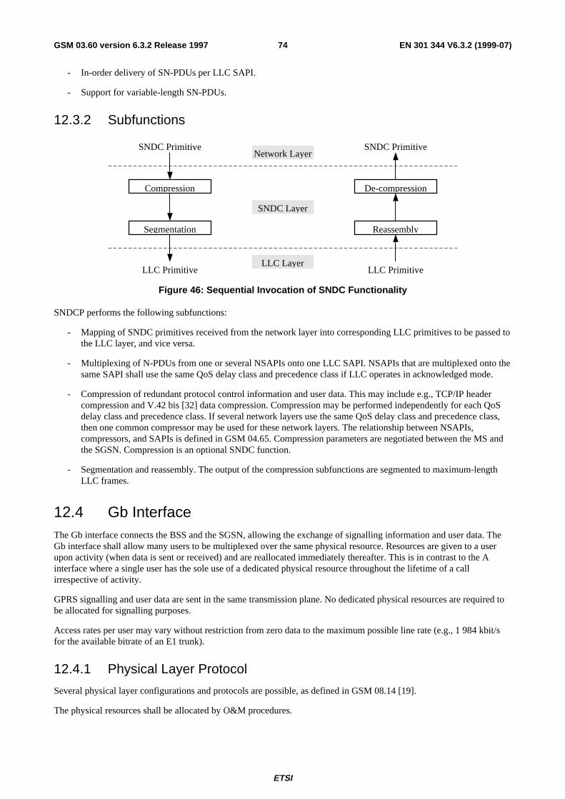
ETSI
EN 301 344 V6.3.2 (1999-07)74GSM 03.60 version 6.3.2 Release 1997
- In-order delivery of SN-PDUs per LLC SAPI.
- Support for variable-length SN-PDUs.
12.3.2 Subfunctions
Compression
Segmentation Reassembly
De-compression
SNDC Primitive SNDC Primitive
LLC Primitive LLC Primitive
Network Layer
SNDC Layer
LLC Layer
Figure 46: Sequential Invocation of SNDC Functionality
SNDCP performs the following subfunctions:
- Mapping of SNDC primitives received from the network layer into corresponding LLC primitives to be passed tothe LLC layer, and vice versa.
- Multiplexing of N-PDUs from one or several NSAPIs onto one LLC SAPI. NSAPIs that are multiplexed onto thesame SAPI shall use the same QoS delay class and precedence class if LLC operates in acknowledged mode.
- Compression of redundant protocol control information and user data. This may include e.g., TCP/IP headercompression and V.42 bis [32] data compression. Compression may be performed independently for each QoSdelay class and precedence class. If several network layers use the same QoS delay class and precedence class,then one common compressor may be used for these network layers. The relationship between NSAPIs,compressors, and SAPIs is defined in GSM 04.65. Compression parameters are negotiated between the MS andthe SGSN. Compression is an optional SNDC function.
- Segmentation and reassembly. The output of the compression subfunctions are segmented to maximum-lengthLLC frames.
12.4 Gb InterfaceThe Gb interface connects the BSS and the SGSN, allowing the exchange of signalling information and user data. TheGb interface shall allow many users to be multiplexed over the same physical resource. Resources are given to a userupon activity (when data is sent or received) and are reallocated immediately thereafter. This is in contrast to the Ainterface where a single user has the sole use of a dedicated physical resource throughout the lifetime of a callirrespective of activity.
GPRS signalling and user data are sent in the same transmission plane. No dedicated physical resources are required tobe allocated for signalling purposes.
Access rates per user may vary without restriction from zero data to the maximum possible line rate (e.g., 1 984 kbit/sfor the available bitrate of an E1 trunk).
12.4.1 Physical Layer Protocol
Several physical layer configurations and protocols are possible, as defined in GSM 08.14 [19].
The physical resources shall be allocated by O&M procedures.
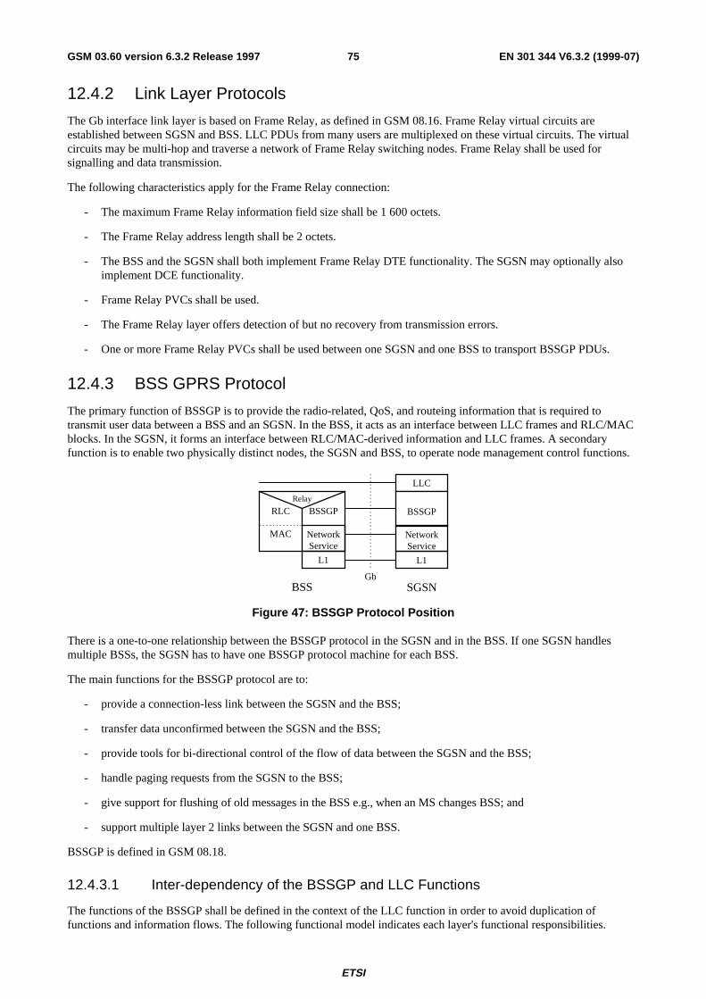
ETSI
EN 301 344 V6.3.2 (1999-07)75GSM 03.60 version 6.3.2 Release 1997
12.4.2 Link Layer Protocols
The Gb interface link layer is based on Frame Relay, as defined in GSM 08.16. Frame Relay virtual circuits areestablished between SGSN and BSS. LLC PDUs from many users are multiplexed on these virtual circuits. The virtualcircuits may be multi-hop and traverse a network of Frame Relay switching nodes. Frame Relay shall be used forsignalling and data transmission.
The following characteristics apply for the Frame Relay connection:
- The maximum Frame Relay information field size shall be 1 600 octets.
- The Frame Relay address length shall be 2 octets.
- The BSS and the SGSN shall both implement Frame Relay DTE functionality. The SGSN may optionally alsoimplement DCE functionality.
- Frame Relay PVCs shall be used.
- The Frame Relay layer offers detection of but no recovery from transmission errors.
- One or more Frame Relay PVCs shall be used between one SGSN and one BSS to transport BSSGP PDUs.
12.4.3 BSS GPRS Protocol
The primary function of BSSGP is to provide the radio-related, QoS, and routeing information that is required totransmit user data between a BSS and an SGSN. In the BSS, it acts as an interface between LLC frames and RLC/MACblocks. In the SGSN, it forms an interface between RLC/MAC-derived information and LLC frames. A secondaryfunction is to enable two physically distinct nodes, the SGSN and BSS, to operate node management control functions.
GbBSS
NetworkService
RLC
MAC
BSSGP
L1
Relay
LLC
BSSGP
L1
SGSN
NetworkService
Figure 47: BSSGP Protocol Position
There is a one-to-one relationship between the BSSGP protocol in the SGSN and in the BSS. If one SGSN handlesmultiple BSSs, the SGSN has to have one BSSGP protocol machine for each BSS.
The main functions for the BSSGP protocol are to:
- provide a connection-less link between the SGSN and the BSS;
- transfer data unconfirmed between the SGSN and the BSS;
- provide tools for bi-directional control of the flow of data between the SGSN and the BSS;
- handle paging requests from the SGSN to the BSS;
- give support for flushing of old messages in the BSS e.g., when an MS changes BSS; and
- support multiple layer 2 links between the SGSN and one BSS.
BSSGP is defined in GSM 08.18.
12.4.3.1 Inter-dependency of the BSSGP and LLC Functions
The functions of the BSSGP shall be defined in the context of the LLC function in order to avoid duplication offunctions and information flows. The following functional model indicates each layer's functional responsibilities.
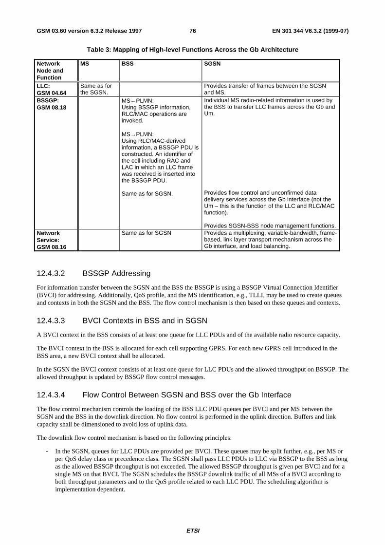
ETSI
EN 301 344 V6.3.2 (1999-07)76GSM 03.60 version 6.3.2 Release 1997
Table 3: Mapping of High-level Functions Across the Gb Architecture
NetworkNode andFunction
MS BSS SGSN
LLC:GSM 04.64
Same as forthe SGSN.
Provides transfer of frames between the SGSNand MS.
BSSGP:GSM 08.18
MS←PLMN:Using BSSGP information,RLC/MAC operations areinvoked.
MS→PLMN:Using RLC/MAC-derivedinformation, a BSSGP PDU isconstructed. An identifier ofthe cell including RAC andLAC in which an LLC framewas received is inserted intothe BSSGP PDU.
Same as for SGSN.
Individual MS radio-related information is used bythe BSS to transfer LLC frames across the Gb andUm.
Provides flow control and unconfirmed datadelivery services across the Gb interface (not theUm – this is the function of the LLC and RLC/MACfunction).
Provides SGSN-BSS node management functions.NetworkService:GSM 08.16
Same as for SGSN Provides a multiplexing, variable-bandwidth, frame-based, link layer transport mechanism across theGb interface, and load balancing.
12.4.3.2 BSSGP Addressing
For information transfer between the SGSN and the BSS the BSSGP is using a BSSGP Virtual Connection Identifier(BVCI) for addressing. Additionally, QoS profile, and the MS identification, e.g., TLLI, may be used to create queuesand contexts in both the SGSN and the BSS. The flow control mechanism is then based on these queues and contexts.
12.4.3.3 BVCI Contexts in BSS and in SGSN
A BVCI context in the BSS consists of at least one queue for LLC PDUs and of the available radio resource capacity.
The BVCI context in the BSS is allocated for each cell supporting GPRS. For each new GPRS cell introduced in theBSS area, a new BVCI context shall be allocated.
In the SGSN the BVCI context consists of at least one queue for LLC PDUs and the allowed throughput on BSSGP. Theallowed throughput is updated by BSSGP flow control messages.
12.4.3.4 Flow Control Between SGSN and BSS over the Gb Interface
The flow control mechanism controls the loading of the BSS LLC PDU queues per BVCI and per MS between theSGSN and the BSS in the downlink direction. No flow control is performed in the uplink direction. Buffers and linkcapacity shall be dimensioned to avoid loss of uplink data.
The downlink flow control mechanism is based on the following principles:
- In the SGSN, queues for LLC PDUs are provided per BVCI. These queues may be split further, e.g., per MS orper QoS delay class or precedence class. The SGSN shall pass LLC PDUs to LLC via BSSGP to the BSS as longas the allowed BSSGP throughput is not exceeded. The allowed BSSGP throughput is given per BVCI and for asingle MS on that BVCI. The SGSN schedules the BSSGP downlink traffic of all MSs of a BVCI according toboth throughput parameters and to the QoS profile related to each LLC PDU. The scheduling algorithm isimplementation dependent.
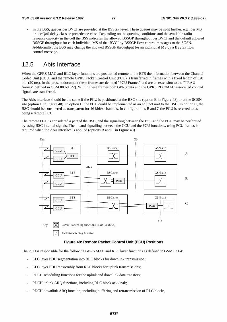
ETSI
EN 301 344 V6.3.2 (1999-07)77GSM 03.60 version 6.3.2 Release 1997
- In the BSS, queues per BVCI are provided at the BSSGP level. These queues may be split further, e.g., per MSor per QoS delay class or precedence class. Depending on the queuing conditions and the available radioresource capacity in the cell the BSS indicates the allowed BSSGP throughput per BVCI and the default allowedBSSGP throughput for each individual MS of that BVCI by BSSGP flow control messages to the SGSN.Additionally, the BSS may change the allowed BSSGP throughput for an individual MS by a BSSGP flowcontrol message.
12.5 Abis InterfaceWhen the GPRS MAC and RLC layer functions are positioned remote to the BTS the information between the ChannelCodec Unit (CCU) and the remote GPRS Packet Control Unit (PCU) is transferred in frames with a fixed length of 320bits (20 ms). In the present document these frames are denoted "PCU Frames" and are an extension to the "TRAUframes" defined in GSM 08.60 [22]. Within these frames both GPRS data and the GPRS RLC/MAC associated controlsignals are transferred.
The Abis interface should be the same if the PCU is positioned at the BSC site (option B in Figure 48) or at the SGSNsite (option C in Figure 48). In option B, the PCU could be implemented as an adjunct unit to the BSC. In option C, theBSC should be considered as transparent for 16 kbit/s channels. In configurations B and C the PCU is referred to asbeing a remote PCU.
The remote PCU is considered a part of the BSC, and the signalling between the BSC and the PCU may be performedby using BSC internal signals. The inband signalling between the CCU and the PCU functions, using PCU frames isrequired when the Abis interface is applied (options B and C in Figure 48).
Abis
BTS BSC site GSN site
BSC site GSN site
BSC site GSN site
CCU
PCUCCU
BTSCCU
CCU
BTSCCU
CCU
Um Gb
A
B
C
PCU
PCU
Key: Circuit-switching function (16 or 64 kbit/s)
Packet-switching function
Gb
Figure 48: Remote Packet Control Unit (PCU) Positions
The PCU is responsible for the following GPRS MAC and RLC layer functions as defined in GSM 03.64:
- LLC layer PDU segmentation into RLC blocks for downlink transmission;
- LLC layer PDU reassembly from RLC blocks for uplink transmissions;
- PDCH scheduling functions for the uplink and downlink data transfers;
- PDCH uplink ARQ functions, including RLC block ack / nak;
- PDCH downlink ARQ function, including buffering and retransmission of RLC blocks;
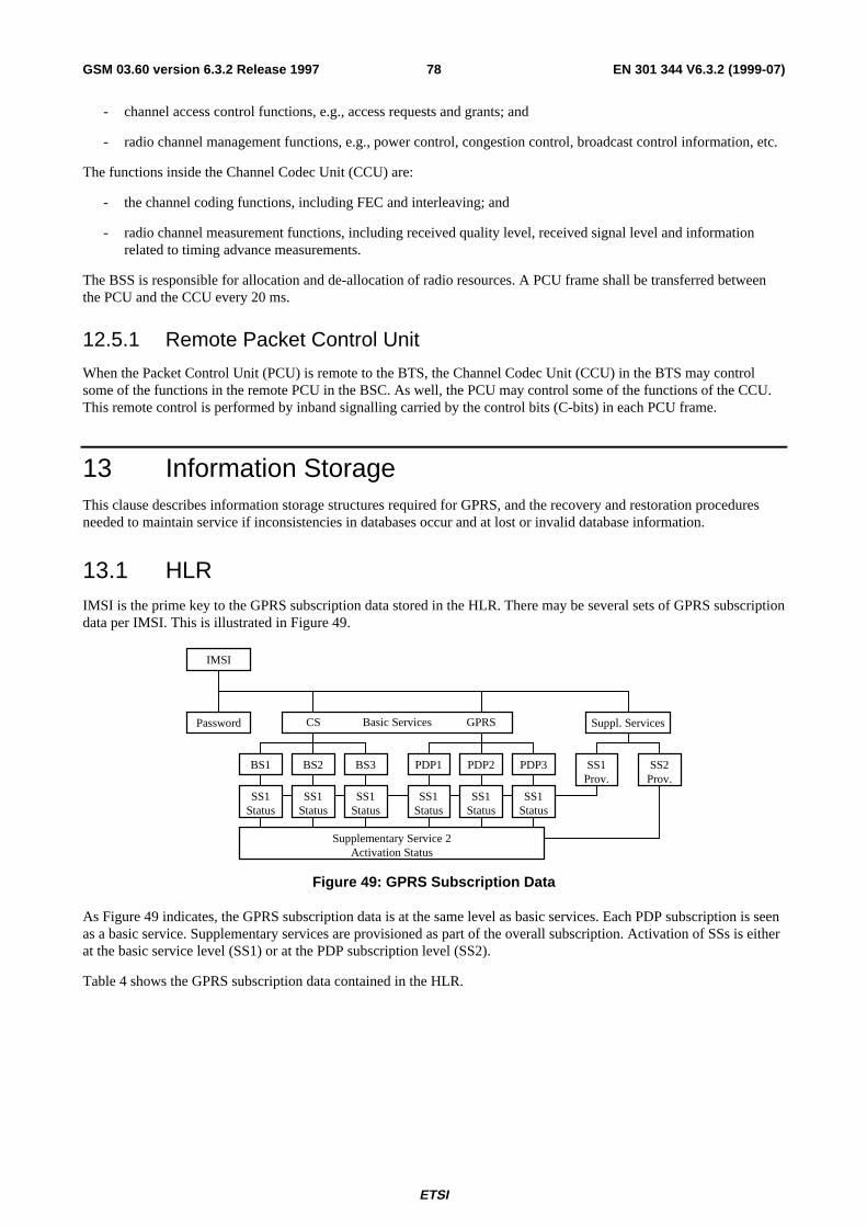
ETSI
EN 301 344 V6.3.2 (1999-07)78GSM 03.60 version 6.3.2 Release 1997
- channel access control functions, e.g., access requests and grants; and
- radio channel management functions, e.g., power control, congestion control, broadcast control information, etc.
The functions inside the Channel Codec Unit (CCU) are:
- the channel coding functions, including FEC and interleaving; and
- radio channel measurement functions, including received quality level, received signal level and informationrelated to timing advance measurements.
The BSS is responsible for allocation and de-allocation of radio resources. A PCU frame shall be transferred betweenthe PCU and the CCU every 20 ms.
12.5.1 Remote Packet Control Unit
When the Packet Control Unit (PCU) is remote to the BTS, the Channel Codec Unit (CCU) in the BTS may controlsome of the functions in the remote PCU in the BSC. As well, the PCU may control some of the functions of the CCU.This remote control is performed by inband signalling carried by the control bits (C-bits) in each PCU frame.
13 Information StorageThis clause describes information storage structures required for GPRS, and the recovery and restoration proceduresneeded to maintain service if inconsistencies in databases occur and at lost or invalid database information.
13.1 HLRIMSI is the prime key to the GPRS subscription data stored in the HLR. There may be several sets of GPRS subscriptiondata per IMSI. This is illustrated in Figure 49.
IMSI
Password CS GPRS Suppl. Services
BS1 BS3BS2
SS1Status
SS1Status
SS1Status
PDP1 PDP3PDP2
SS1Status
SS1Status
SS1Status
SS2Prov.
SS1Prov.
Supplementary Service 2Activation Status
Basic Services
Figure 49: GPRS Subscription Data
As Figure 49 indicates, the GPRS subscription data is at the same level as basic services. Each PDP subscription is seenas a basic service. Supplementary services are provisioned as part of the overall subscription. Activation of SSs is eitherat the basic service level (SS1) or at the PDP subscription level (SS2).
Table 4 shows the GPRS subscription data contained in the HLR.
ETSI
EN 301 344 V6.3.2 (1999-07)79GSM 03.60 version 6.3.2 Release 1997
Table 4: HLR GPRS Subscription Data
Field DescriptionIMSI IMSI is the main reference key.MSISDN The basic MSISDN of the MS.SGSN Number The SS7 number of the SGSN currently serving this MS.SGSN Address The IP address of the SGSN currently serving this MS.SMS Parameters SMS-related parameters, e.g., operator-determined barring.MS Purged for GPRS Indicates that the MM and PDP contexts of the MS are deleted from the SGSN.MNRG Indicates that the MS is not reachable through an SGSN, and that the MS is marked
as not reachable for GPRS at the SGSN and possibly at the GGSN.GGSN-list The GSN number and optional IP address pair related to the GGSN that shall be
contacted when activity from the MS is detected and MNRG is set. The GSN numbershall be either the number of the GGSN or the protocol-converting GSN as describedin the subclauses "MAP-based GGSN - HLR Signalling" and "GTP and MAP-basedGGSN - HLR Signalling".
Each IMSI contains zero or more of the following PDP context subscription records:PDP Context Identifier Index of the PDP context.PDP Type PDP type, e.g., X.25 or IP.PDP Address PDP address, e.g., an X.121 address. This field shall be empty if dynamic
addressing is allowed.QoS Profile Subscribed The quality of service profile subscribed. QoS Profile Subscribed is the default level if
a particular QoS profile is not requested.VPLMN Address Allowed Specifies whether the MS is allowed to use the APN in the domain of the HPLMN
only, or additionally the APN in the domain of the VPLMN.Access Point Name A label according to DNS naming conventions describing the access point to the
external packet data network.
ETSI
EN 301 344 V6.3.2 (1999-07)80GSM 03.60 version 6.3.2 Release 1997
13.2 SGSNSGSN maintains MM context and PDP context information for MSs in STANDBY and READY states. Table 5 showsthe context fields for one MS.
Table 5: SGSN MM and PDP Contexts
Field DescriptionIMSI IMSI is the main reference key.MM State Mobility management state, IDLE, STANDBY, or READY.P-TMSI Packet Temporary Mobile Subscriber Identity.IMEI International Mobile Equipment IdentityP-TMSI Signature A signature used for identification checking purposes.Routeing Area Current routeing area.Cell Identity Current cell in READY state, last known cell in STANDBY or IDLE state.Cell Identity Age Time elapsed since the last LLC PDU was received from the MS at the SGSN.VLR Number The VLR number of the MSC/VLR currently serving this MS.New SGSN Address The IP address of the new SGSN where buffered and not sent N-PDUs should be
forwarded to.Authentication Triplets Authentication and ciphering parameters.Kc Currently used ciphering key.CKSN Ciphering key sequence number of Kc.Ciphering algorithm Selected ciphering algorithm.Radio Access Classmark MS radio access capabilities.SGSN Classmark MS network capabilities.DRX Parameters Discontinuous reception parameters.MNRG Indicates whether activity from the MS shall be reported to the HLR.NGAF Indicates whether activity from the MS shall be reported to the MSC/VLR.PPF Indicates whether paging for GPRS and non-GPRS services can be initiated.MSISDN The basic MSISDN of the MS.SMS Parameters SMS-related parameters, e.g., operator-determined barring.Recovery Indicates if HLR or VLR is performing database recovery.Radio Priority SMS The RLC/MAC radio priority level for uplink SMS transmission.Each MM context contains zero or more of the following PDP contexts:PDP Context Identifier Index of the PDP context.PDP Type PDP type, e.g., X.25 or IP.PDP Address PDP address, e.g., an X.121 address.NSAPI Network layer Service Access Point Identifier.TI Transaction Identifier.PDP State Packet data protocol state, INACTIVE or ACTIVE.Access Point Name The APN requested by the MS.GGSN Address in Use The IP address of the GGSN currently used by the activated PDP context.VPLMN Address Allowed Specifies whether the MS is allowed to use the APN in the domain of the HPLMN
only, or additionally the APN in the domain of the VPLMN.QoS Profile Subscribed The quality of service profile subscribed.QoS Profile Requested The quality of service profile requested.QoS Profile Negotiated The quality of service profile negotiated.Radio Priority The RLC/MAC radio priority level for uplink user data transmission.SND GTP sequence number of the next downlink N-PDU to be sent to the MS.SNU GTP sequence number of the next uplink N-PDU to be sent to the GGSN.Charging Id Charging identifier, identifies charging records generated by SGSN and GGSN.Reordering Required Specifies whether the SGSN shall reorder N-PDUs before delivering the N-PDUs to
the MS.

ETSI
EN 301 344 V6.3.2 (1999-07)81GSM 03.60 version 6.3.2 Release 1997
In case of anonymous access the SGSN maintains the MM context and PDP context information for MSs in READYstate. Table 6 shows the context fields for one MS.
Table 6: SGSN MM and PDP Contexts for Anonymous Access
Field DescriptionA-TLLI Auxiliary Temporary Logical Link Identity.AA-TID Anonymous Access Tunnel Identifier.Routeing Area Current routeing area.Cell Identity Current cell.PDP Type PDP type, e.g., X.25 or IP.PDP Address PDP address, e.g., an X.121 address.NSAPI Network layer Service Access Point Identifier.TI Transaction Identifier.QoS Profile Negotiated The quality of service profile negotiated.QoS Profile Requested The quality of service profile requested.GGSN Address in Use The IP address of the GGSN currently used.Radio Priority The RLC/MAC radio priority level for uplink user data transmission.SND GTP sequence number of the next downlink N-PDU to be sent to the MS.SNU GTP sequence number of the next uplink N-PDU to be sent to the GGSN.Charging Id Charging identifier, identifies charging records generated by SGSN and GGSN.Reordering Required Specifies whether the SGSN shall reorder N-PDUs before delivering the N-PDUs to
the MS.
13.3 GGSNGGSN maintains activated PDP contexts. Table 7 shows the PDP context fields for one PDP Address.
Table 7: GGSN PDP Context
Field DescriptionIMSI International Mobile Subscriber Identity.NSAPI Network layer Service Access Point Identifier.PDP Type PDP type, e.g., X.25 or IP.PDP Address PDP address, e.g., an X.121 address.Dynamic Address Indicates whether PDP Address is static or dynamic.QoS Profile Negotiated The quality of service profile negotiated.SGSN Address The IP address of the SGSN currently serving this MS.Access Point Name The APN requested by the MS.MNRG Indicates whether the MS is marked as not reachable for GPRS at the HLR.Recovery Indicates if the SGSN is performing database recovery.SND GTP sequence number of the next downlink N-PDU to be sent to the MS.SNU GTP sequence number of the next uplink N-PDU to be received from the SGSN.Charging Id Charging identifier, identifies charging records generated by SGSN and GGSN.Reordering Required Specifies whether the GGSN shall reorder N-PDUs received from the SGSN.
ETSI
EN 301 344 V6.3.2 (1999-07)82GSM 03.60 version 6.3.2 Release 1997
If a PDP context is enabled for network-requested PDP context activation, then IMSI, PDP Type, PDP Address, SGSNAddress and MNRG contain valid information also when the PDP context is inactive and when the MS is GPRS-detached.
In case of anonymous access the GGSN maintains activated PDP contexts. Table 8 shows the PDP context fields for oneMS.
Table 8: GGSN PDP Context for Anonymous Access
Field DescriptionAA-TID Anonymous Access Tunnel Identifier.PDP Type PDP type, e.g., X.25 or IP.PDP Address PDP address, e.g., an X.121 address.QoS Profile Negotiated The quality of service profile negotiated.SGSN Address The IP address of the SGSN serving this MS.Access Point Name The APN requested by the MS.SND GTP sequence number of the next downlink N-PDU to be sent to the MS.SNU GTP sequence number of the next uplink N-PDU to be sent to the GGSN.Charging Id Charging identifier, identifies charging records generated by SGSN and GGSN.Reordering Required Specifies whether the GGSN shall reorder N-PDUs received from the SGSN.
A GGSN that supports anonymous access shall have a list of server addresses that are allowed to be accessed byanonymous MSs. The method to maintain the list of the servers is outside the scope of the present document.
13.4 MSEach GPRS MS maintains MM and PDP context information in IDLE, STANDBY and READY states. The informationmay be contained in the MS and the TE. Table 9 shows the MS context fields.
Table 9: MS MM and PDP Contexts
Field SIM DescriptionIMSI X International Mobile Subscriber Identity.MM State Mobility management state, IDLE, STANDBY, or READY.P-TMSI X Packet Temporary Mobile Subscriber Identity.P-TMSI Signature X A signature used for identification checking purposes.Routeing Area X Current routeing area.Cell Identity Current cell.Kc X Currently used ciphering key.CKSN X Ciphering key sequence number of Kc.Ciphering algorithm Selected ciphering algorithm.Classmark MS classmark.DRX Parameters Discontinuous reception parameters.Radio Priority SMS The RLC/MAC radio priority level for uplink SMS transmission.Each MM context contains zero or more of the following PDP contexts:PDP Type PDP type, e.g., X.25 or IP.PDP Address PDP address, e.g., an X.121 address.PDP State Packet data protocol state, INACTIVE or ACTIVE.Dynamic Address Allowed Specifies whether the MS is allowed to use a dynamic address.NSAPI Network layer Service Access Point Identifier.TI Transaction Identifier.QoS Profile Requested The quality of service profile requested.QoS Profile Negotiated The quality of service profile negotiated.Radio Priority The RLC/MAC radio priority level for uplink user data transmission.
The information marked with an "X" in Table 9:
- shall be stored in the SIM if the connected SIM is GPRS-aware; and
- may be stored in the ME after GPRS detach if the connected SIM is not GPRS-aware.
ETSI
EN 301 344 V6.3.2 (1999-07)83GSM 03.60 version 6.3.2 Release 1997
If the SIM is GPRS-aware, then the IMSI, P-TMSI, P-TMSI Signature, Routeing Area, Kc, and CKSN stored in theSIM shall be used when accessing the GPRS services.
If the SIM is not GPRS-aware, then the P-TMSI, P-TMSI Signature, Routeing Area, Kc, and CKSN stored in the MEshall be used if and only if the IMSI stored in the SIM is identical to the IMSI image maintained in the ME. If the IMSIstored in the SIM is different from the IMSI image in the ME, then the IMSI image in the ME shall not be used, and theMS shall identify itself with the IMSI stored in the SIM when performing a GPRS attach. IMSI, P-TMSI, P-TMSISignature, Routeing Area, Kc, and CKSN may be stored in the ME after the GPRS attach has been successfullyperformed.
For anonymous access each GPRS MS maintains MM and PDP context information in READY state. The informationmay be contained in the ME and the TE. Table 10 shows the MS context fields.
Table 10: MS MM and PDP Contexts for Anonymous Access
Field DescriptionA-TLLI Auxiliary Temporary Logical Link Identity.Routeing Area Current routeing area.Cell Identity Current cell.PDP Type PDP type, e.g., X.25 or IP.PDP Address PDP address, e.g., an X.121 address.NSAPI Network layer Service Access Point Identifier.TI Transaction Identifier.QoS Profile Requested The quality of service profile requested.QoS Profile Negotiated The quality of service profile negotiated.Radio Priority The RLC/MAC radio priority level for uplink user data transmission.
13.5 MSC/VLRThe MSC/VLR may store the SGSN number of GPRS-attached MSs that are also IMSI-attached. Table 11 shows theMSC/VLR association for one MS.
Table 11: MSC/VLR Association
Field DescriptionIMSI IMSI is the main reference key.SGSN Number The SGSN number of the SGSN currently serving this MS.
13.6 Recovery and Restoration ProceduresThe recovery and restoration procedures are intended to maintain service if inconsistencies in databases occur and at lostor invalid database information. "Invalid" in this context means that the database entry cannot be regarded as reliable.
13.6.1 HLR Failure
When an HLR restarts, it sends to each SGSN where one or more of its MSs are registered a Reset message. This causesthe SGSN to mark the relevant MM contexts as invalid, and to set NGAF if an SGSN – MSC/VLR association exists.After receipt of the first valid LLC frame from a marked MS, the SGSN performs an update location to the HLR as inthe attach or inter SGSN RA update procedures, and, if NGAF is set, the procedure in subclause "Non-GPRS Alert" isfollowed. The update location procedure and the procedure towards the MSC/VLR may be delayed by the SGSN for amaximum operator configuration-depending time period to avoid high signalling load. The periodic back-up of HLRdata to non-volatile storage is mandatory as described in GSM 03.07 [5].
ETSI
EN 301 344 V6.3.2 (1999-07)84GSM 03.60 version 6.3.2 Release 1997
13.6.2 SGSN Failure
When an SGSN fails, it deletes all MM and PDP contexts affected by the failure. SGSN storage of subscriber data isvolatile. Based on configuration data, the SGSN shall send a Reset message to each of its associated VLRs. The VLRsshall mark all associations containing the restarted SGSN as unreliable.
If data or signalling, except GPRS attach and RA update, is received in an SGSN from an MS for which no MM contextexists in the SGSN, the SGSN shall discard the data or signalling.
If an RA update request is received in an SGSN from an MS for which no MM context exists in the SGSN, the SGSNshall command the MS to make a new GPRS attach and PDP context activations. The MS requests the re-activation ofthe PDP contexts with the same NSAPI value per PDP address as in the previous connection. This re-activates the MMand PDP contexts in the SGSN and GGSN.
When the SGSN receives a tunnel PDU for which no PDP context exists it discards the tunnel PDU and sends an errorindication to the originating GGSN. The GGSN marks the related PDP context as invalid. The SGSN may search theMS by paging with the IMSI in the SGSN area if there is no MM context for the MS. When the MS responds to paging,the MM and PDP contexts at SGSN and GGSN are re-established as at a mobile-originated transaction described above.
When the SGSN receives a mobile-terminated SM from the SMS-GMSC for an IMSI unknown in the SGSN, it rejectsthe request.
When the SGSN receives a Paging request over the Gs interface for an IMSI unknown in the SGSN and the SGSN hasnot completed recovery (see GSM 03.07), then the SGSN shall page for the MS in the area specified by the locationinformation provided by the MSC/VLR. If no such location information is provided, then the SGSN shall page for theMS in the routeing areas corresponding to that MSC/VLR.
13.6.3 GGSN Failure
When a GGSN fails, all its PDP contexts affected by the failure become invalid and may be deleted. GGSN storage ofsubscriber data is volatile.
When the GGSN receives a tunnel PDU for which no PDP context exists, it shall discard the tunnel PDU and return anerror indication to the originating SGSN. The SGSN shall mark the related PDP context as invalid and send a DeactivatePDP Context Request message to the MS. The MS may then reactivate the PDP context.
13.6.4 VLR Failure
When a VLR fails, all its associations with SGSNs affected by the failure become invalid and may be deleted. Based onconfiguration data, the MSC/VLR sends a BSSAP+ Reset message to each of its associated SGSNs. The SGSNs markall associations containing the restarted VLR as invalid. After receipt of the first valid LLC frame from an MS that isboth GPRS-attached and IMSI-attached, the SGSN shall return a Detach Request (Detach Type) message in order torequest the MS to perform a combined RA / LA update. Detach Type shall be set to IMSI Detach. The detach proceduremay be delayed by the SGSN for a maximum operator-configuration depending time period to avoid high signallingload.
14 Identities
14.1 IMSIA unique International Mobile Subscriber Identity (IMSI) shall be allocated to each mobile subscriber in GSM. This isalso the case for GPRS-only mobile subscribers, except for anonymous-only access subscribers. IMSI is defined inGSM 03.03 [4].
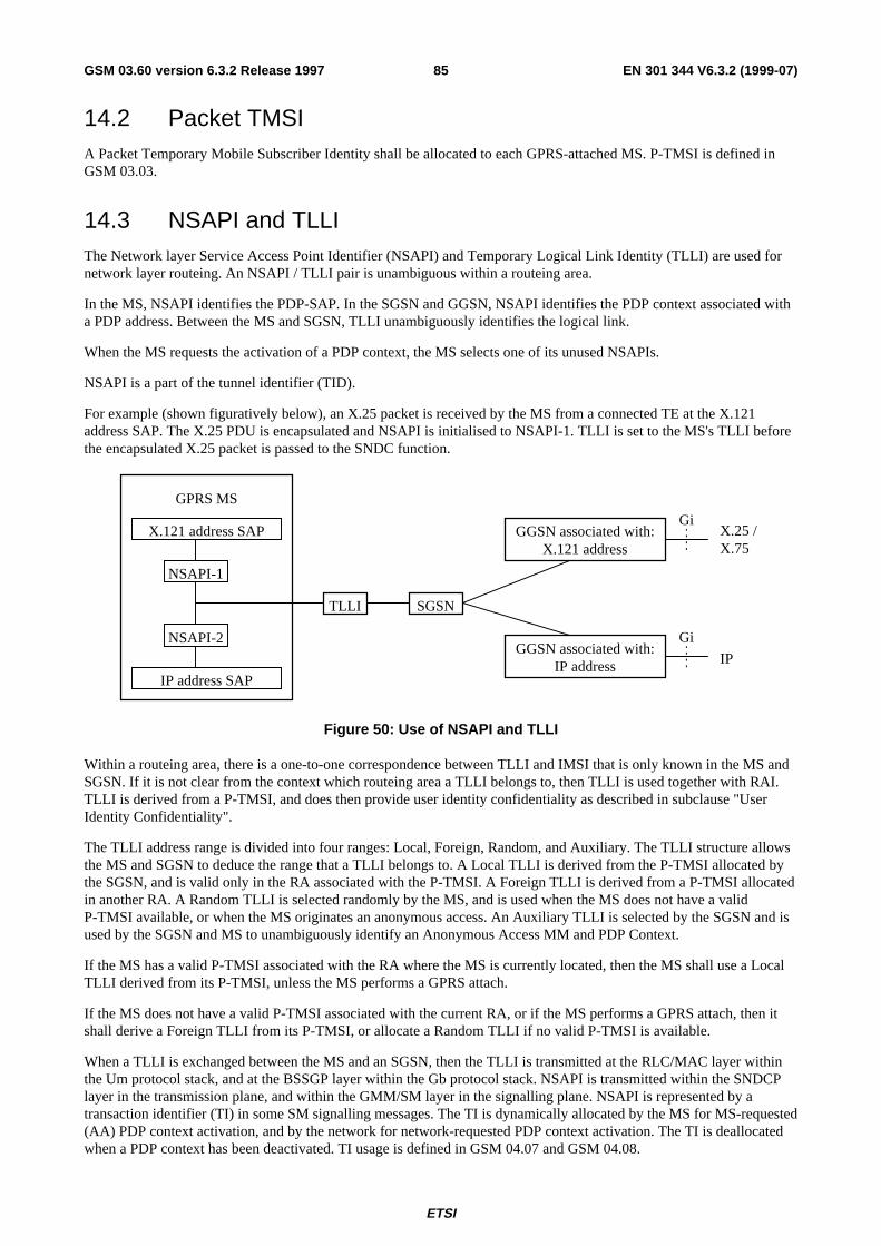
ETSI
EN 301 344 V6.3.2 (1999-07)85GSM 03.60 version 6.3.2 Release 1997
14.2 Packet TMSIA Packet Temporary Mobile Subscriber Identity shall be allocated to each GPRS-attached MS. P-TMSI is defined inGSM 03.03.
14.3 NSAPI and TLLIThe Network layer Service Access Point Identifier (NSAPI) and Temporary Logical Link Identity (TLLI) are used fornetwork layer routeing. An NSAPI / TLLI pair is unambiguous within a routeing area.
In the MS, NSAPI identifies the PDP-SAP. In the SGSN and GGSN, NSAPI identifies the PDP context associated witha PDP address. Between the MS and SGSN, TLLI unambiguously identifies the logical link.
When the MS requests the activation of a PDP context, the MS selects one of its unused NSAPIs.
NSAPI is a part of the tunnel identifier (TID).
For example (shown figuratively below), an X.25 packet is received by the MS from a connected TE at the X.121address SAP. The X.25 PDU is encapsulated and NSAPI is initialised to NSAPI-1. TLLI is set to the MS's TLLI beforethe encapsulated X.25 packet is passed to the SNDC function.
GGSN associated with:X.121 address
TLLI
X.121 address SAP
IP address SAP
NSAPI-1
NSAPI-2
Gi
GGSN associated with:IP address
Gi
GPRS MS
SGSN
X.25 /X.75
IP
Figure 50: Use of NSAPI and TLLI
Within a routeing area, there is a one-to-one correspondence between TLLI and IMSI that is only known in the MS andSGSN. If it is not clear from the context which routeing area a TLLI belongs to, then TLLI is used together with RAI.TLLI is derived from a P-TMSI, and does then provide user identity confidentiality as described in subclause "UserIdentity Confidentiality".
The TLLI address range is divided into four ranges: Local, Foreign, Random, and Auxiliary. The TLLI structure allowsthe MS and SGSN to deduce the range that a TLLI belongs to. A Local TLLI is derived from the P-TMSI allocated bythe SGSN, and is valid only in the RA associated with the P-TMSI. A Foreign TLLI is derived from a P-TMSI allocatedin another RA. A Random TLLI is selected randomly by the MS, and is used when the MS does not have a validP-TMSI available, or when the MS originates an anonymous access. An Auxiliary TLLI is selected by the SGSN and isused by the SGSN and MS to unambiguously identify an Anonymous Access MM and PDP Context.
If the MS has a valid P-TMSI associated with the RA where the MS is currently located, then the MS shall use a LocalTLLI derived from its P-TMSI, unless the MS performs a GPRS attach.
If the MS does not have a valid P-TMSI associated with the current RA, or if the MS performs a GPRS attach, then itshall derive a Foreign TLLI from its P-TMSI, or allocate a Random TLLI if no valid P-TMSI is available.
When a TLLI is exchanged between the MS and an SGSN, then the TLLI is transmitted at the RLC/MAC layer withinthe Um protocol stack, and at the BSSGP layer within the Gb protocol stack. NSAPI is transmitted within the SNDCPlayer in the transmission plane, and within the GMM/SM layer in the signalling plane. NSAPI is represented by atransaction identifier (TI) in some SM signalling messages. The TI is dynamically allocated by the MS for MS-requested(AA) PDP context activation, and by the network for network-requested PDP context activation. The TI is deallocatedwhen a PDP context has been deactivated. TI usage is defined in GSM 04.07 and GSM 04.08.
ETSI
EN 301 344 V6.3.2 (1999-07)86GSM 03.60 version 6.3.2 Release 1997
By default, unless explicitly specified in the procedures, the TLLI transmitted at the RLC/MAC and BSSGP layers shallbe used to identify the MS.
14.4 PDP AddressA GPRS subscriber identified by an IMSI, shall have one or more network layer addresses, i.e., PDP addresses,temporarily and/or permanently associated with it that conforms to the standard addressing scheme of the respectivenetwork layer service used, e.g.:
- an IP version 4 address;
- an IP version 6 address; or
- an X.121 address.
PDP addresses are activated and deactivated through MM procedures described in subclause "PDP Context Activation,Modification, and Deactivation Functions".
14.5 TIDA Tunnel Identifier (TID) is used by the GPRS Tunnelling protocol between GSNs to identify a PDP context. A TIDconsists of an IMSI and an NSAPI. The combination of IMSI and NSAPI uniquely identifies a single PDP context.
The TID is forwarded to the GGSN upon PDP Context Activation and it is used in subsequent tunnelling of user databetween the GGSN and the SGSN to identify the MS's PDP contexts in the SGSN and GGSN. The TID is also used toforward N-PDUs from the old SGSN to the new SGSN at and after an inter SGSN routeing area update.
In the anonymous access case, AA-TID is allocated locally by the SGSN. An AA-TID consists of an A-TLLI and anNSAPI similar to TID. Since the IMSI is longer than A-TLLI, the unused digits shall be used to create a unique identitywithin one PLMN. The allocated AA-TID shall not collide with the TID address space.
14.6 Routeing Area IdentityRouteing Area Identity (RAI), defined by an operator, identifies one or several cells. RAI is broadcast as systeminformation and is used by the MS to determine, when changing cell, if an RA border was crossed. If that was the case,the MS initiates the RA update procedure.
The location of an MS in STANDBY state is known in the SGSN on an RA level. This means that the MS is paged inthe RA where the MS is located when mobile-terminated traffic arrives in the SGSN.
A Routeing Area is a subset of one, and only one, Location Area (LA), meaning that an RA cannot span more than oneLA. An RA is served by only one SGSN.
The following rules apply for the Routeing Area Identity:
- RAC is only unique when presented together with LAI.
- CI is only unique when presented together with LAI or RAI.
- LAI = MCC + MNC + LAC
- RAI = MCC + MNC + LAC + RAC
- CGI = LAI + CI
14.7 Cell IdentityCell Identity (CI) identifies one cell. CI is defined in GSM 03.03.
ETSI
EN 301 344 V6.3.2 (1999-07)87GSM 03.60 version 6.3.2 Release 1997
14.8 GSN Addresses
14.8.1 GSN Address
Each SGSN and GGSN shall have an IP address, either of type IPv4 or IPv6, for inter-communication over the GPRSbackbone network. The IP addresses of GSNs and other GPRS backbone nodes of all PLMNs build a private addressspace that is not accessible from the public Internet. For the GGSN and the SGSN, this IP address may also correspondto one or more DNS-type logical GSN names.
14.8.2 GSN Number
Each SGSN shall have an SGSN number for communication with e.g., HLR and EIR.
Each GGSN that supports the optional SS7-based Gc interface shall have a GGSN number for communication withHLRs.
14.9 Access Point NameIn the GPRS backbone, Access Point Name is a reference to the GGSN to be used. In addition, Access Point Name may,in the GGSN, identify the external network. Access Point Name is composed of two parts as defined in GSM 03.03:
- The APN Network Identifier is mandatory and is a label (for example "corporation") or a set of labels separatedby dots which is a fully qualified domain name according to the DNS naming conventions (for example"company.com"). In order to guarantee the uniqueness of the APN, the GPRS PLMN should allocate, to an ISPor corporation, an APN Network Identifier identical to their domain name in the public Internet. The APNNetwork Identifier shall not end with ".gprs".
- The APN Operator Identifier is optional. It is a fully qualified domain name according to the DNS namingconventions, and consists of three labels. The APN Operator Identifier shall end in ".gprs". For example, it maybe "MNCyyyy.MCCzzzz.gprs". The exact format is defined in GSM 09.60.
The APN stored in the HLR shall not contain the APN Operator Identifier. A wild card may be stored in the HLRinstead of the APN. This wild card indicates that the user may select an APN that is not stored in the HLR. The use ofthe wild card is described in annex A.
15 Operational Aspects
15.1 ChargingCharging information in the GPRS network is collected for each MS by SGSNs and GGSNs that are serving the MS.
The information that the operator uses to generate a bill to a subscriber is operator-specific. Billing aspects, e.g., aregular fee for a fixed period, are outside the scope of the present document.
Every GPRS operator collects and processes their own charging information.
The SGSN collects charging information for each MS related with the radio network usage while the GGSN collectscharging information for each MS related with the external data network usage. Both GSNs also collect charginginformation on usage of the GPRS network resources.
15.1.1 Charging Information
PTP charging information is collected for the GPRS subscriber.
ETSI
EN 301 344 V6.3.2 (1999-07)88GSM 03.60 version 6.3.2 Release 1997
As a minimum, the SGSN shall collect the following charging information:
- usage of the radio interface: the charging information shall describe the amount of data transmitted in MO andMT directions categorised with QoS and user protocols;
- usage of the packet data protocol addresses: the charging information shall describe how long the MS has usedthe packet data protocol addresses;
- usage of the general GPRS resources: the charging information shall describe the usage of other GPRS-relatedresources and the MS's GPRS network activity (e.g., mobility management); and
- location of MS: HPLMN, VPLMN, plus optional higher-accuracy location information.
As a minimum, the GGSN shall collect the following charging information:
- destination and source: the charging information shall describe the destination and source addresses with a levelof accuracy as defined by the GPRS operator;
- usage of the external data networks: the charging information shall describe the amount of data sent and receivedto and from the external data network;
- usage of the packet data protocol addresses: the charging information shall describe how long the MS has usedthe PDP addresses; and
- location of MS: HPLMN, VPLMN, plus optional higher-accuracy location information.
15.1.2 Reverse Charging
It shall be possible to provide reverse charging as a subscription option. However, reverse charging may not beapplicable to certain external data network protocols.
15.2 Quality of Service ProfileA QoS profile is associated with each PDP context. The QoS profile is considered to be a single parameter with multipledata transfer attributes. It defines the quality of service expected in terms the following attributes:
- precedence class;
- delay class;
- reliability class;
- peak throughput class; and
- mean throughput class.
There are many possible QoS profiles defined by the combinations of the attributes. A PLMN may support only alimited subset of the possible QoS profiles.
During the QoS profile negotiation defined in subclause "Activation Procedures", it shall be possible for the MS torequest a value for each of the QoS attributes, including the HLR-stored subscribed default values. The network shallnegotiate each attribute to a level that is in accordance with the available GPRS resources. The network shall alwaysattempt to provide adequate resources to support the negotiated QoS profiles.
The RLC/MAC layer supports four radio priority levels and an additional level for signalling messages as defined inGSM 03.64 and GSM 04.60. Upon uplink access the MS can indicate one of the four priority levels, and whether thecause for the uplink access is user data or signalling message transmission. This information is used by the BSS todetermine the radio access precedence (i.e., access priority) and the service precedence (i.e., transfer priority undercongested situation), see GSM 04.60. The radio priority levels to be used for transmission of MO SMS shall bedetermined by the SGSN and delivered to the MS in the Attach Accept message. The radio priority level to be used foruser data transmission shall be determined by the SGSN based on the negotiated QoS profile and shall be delivered tothe MS during the PDP Context Activation and PDP Context Modification procedures.
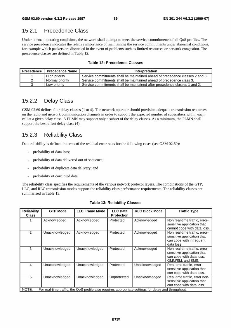
ETSI
EN 301 344 V6.3.2 (1999-07)89GSM 03.60 version 6.3.2 Release 1997
15.2.1 Precedence Class
Under normal operating conditions, the network shall attempt to meet the service commitments of all QoS profiles. Theservice precedence indicates the relative importance of maintaining the service commitments under abnormal conditions,for example which packets are discarded in the event of problems such as limited resources or network congestion. Theprecedence classes are defined in Table 12.
Table 12: Precedence Classes
Precedence Precedence Name Interpretation1 High priority Service commitments shall be maintained ahead of precedence classes 2 and 3.2 Normal priority Service commitments shall be maintained ahead of precedence class 3.3 Low priority Service commitments shall be maintained after precedence classes 1 and 2.
15.2.2 Delay Class
GSM 02.60 defines four delay classes (1 to 4). The network operator should provision adequate transmission resourceson the radio and network communication channels in order to support the expected number of subscribers within eachcell at a given delay class. A PLMN may support only a subset of the delay classes. As a minimum, the PLMN shallsupport the best effort delay class (4).
15.2.3 Reliability Class
Data reliability is defined in terms of the residual error rates for the following cases (see GSM 02.60):
- probability of data loss;
- probability of data delivered out of sequence;
- probability of duplicate data delivery; and
- probability of corrupted data.
The reliability class specifies the requirements of the various network protocol layers. The combinations of the GTP,LLC, and RLC transmission modes support the reliability class performance requirements. The reliability classes aresummarised in Table 13.
Table 13: Reliability Classes
ReliabilityClass
GTP Mode LLC Frame Mode LLC DataProtection
RLC Block Mode Traffic Type
1 Acknowledged Acknowledged Protected Acknowledged Non real-time traffic, error-sensitive application thatcannot cope with data loss.
2 Unacknowledged Acknowledged Protected Acknowledged Non real-time traffic, error-sensitive application thatcan cope with infrequentdata loss.
3 Unacknowledged Unacknowledged Protected Acknowledged Non real-time traffic, error-sensitive application thatcan cope with data loss,GMM/SM, and SMS.
4 Unacknowledged Unacknowledged Protected Unacknowledged Real-time traffic, error-sensitive application thatcan cope with data loss.
5 Unacknowledged Unacknowledged Unprotected Unacknowledged Real-time traffic, error non-sensitive application thatcan cope with data loss.
NOTE: For real-time traffic, the QoS profile also requires appropriate settings for delay and throughput.
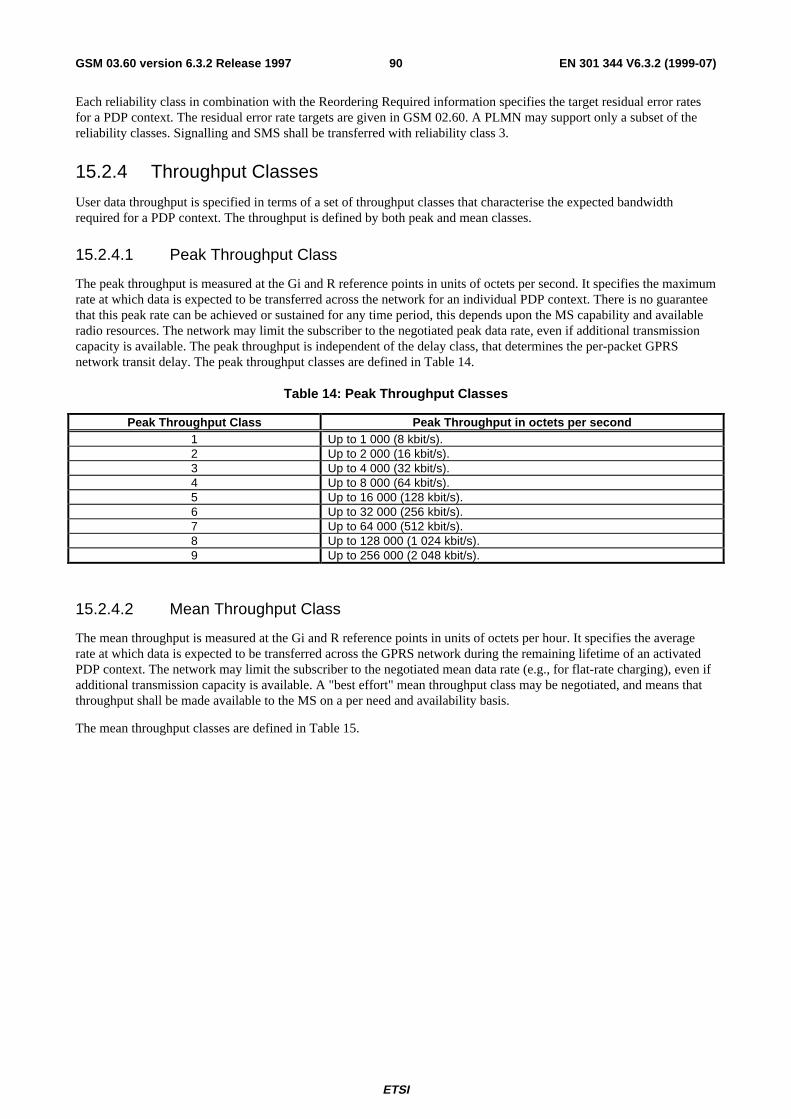
ETSI
EN 301 344 V6.3.2 (1999-07)90GSM 03.60 version 6.3.2 Release 1997
Each reliability class in combination with the Reordering Required information specifies the target residual error ratesfor a PDP context. The residual error rate targets are given in GSM 02.60. A PLMN may support only a subset of thereliability classes. Signalling and SMS shall be transferred with reliability class 3.
15.2.4 Throughput Classes
User data throughput is specified in terms of a set of throughput classes that characterise the expected bandwidthrequired for a PDP context. The throughput is defined by both peak and mean classes.
15.2.4.1 Peak Throughput Class
The peak throughput is measured at the Gi and R reference points in units of octets per second. It specifies the maximumrate at which data is expected to be transferred across the network for an individual PDP context. There is no guaranteethat this peak rate can be achieved or sustained for any time period, this depends upon the MS capability and availableradio resources. The network may limit the subscriber to the negotiated peak data rate, even if additional transmissioncapacity is available. The peak throughput is independent of the delay class, that determines the per-packet GPRSnetwork transit delay. The peak throughput classes are defined in Table 14.
Table 14: Peak Throughput Classes
Peak Throughput Class Peak Throughput in octets per second1 Up to 1 000 (8 kbit/s).2 Up to 2 000 (16 kbit/s).3 Up to 4 000 (32 kbit/s).4 Up to 8 000 (64 kbit/s).5 Up to 16 000 (128 kbit/s).6 Up to 32 000 (256 kbit/s).7 Up to 64 000 (512 kbit/s).8 Up to 128 000 (1 024 kbit/s).9 Up to 256 000 (2 048 kbit/s).
15.2.4.2 Mean Throughput Class
The mean throughput is measured at the Gi and R reference points in units of octets per hour. It specifies the averagerate at which data is expected to be transferred across the GPRS network during the remaining lifetime of an activatedPDP context. The network may limit the subscriber to the negotiated mean data rate (e.g., for flat-rate charging), even ifadditional transmission capacity is available. A "best effort" mean throughput class may be negotiated, and means thatthroughput shall be made available to the MS on a per need and availability basis.
The mean throughput classes are defined in Table 15.
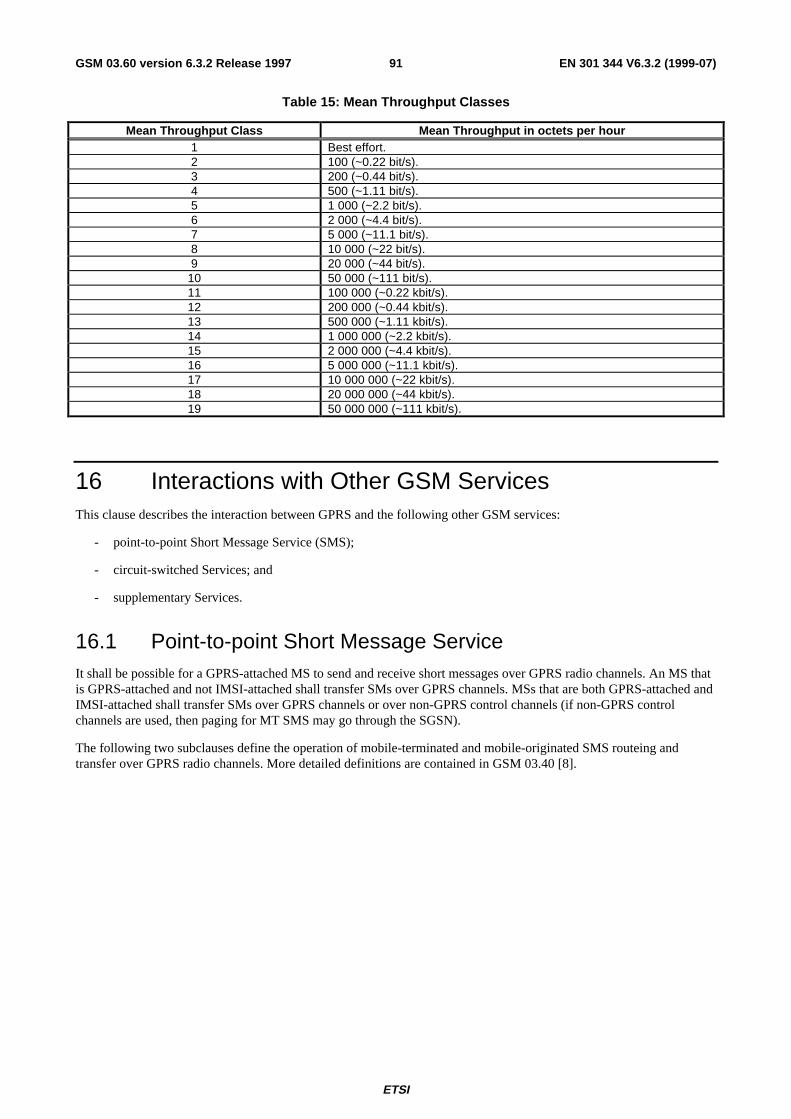
ETSI
EN 301 344 V6.3.2 (1999-07)91GSM 03.60 version 6.3.2 Release 1997
Table 15: Mean Throughput Classes
Mean Throughput Class Mean Throughput in octets per hour1 Best effort.2 100 (~0.22 bit/s).3 200 (~0.44 bit/s).4 500 (~1.11 bit/s).5 1 000 (~2.2 bit/s).6 2 000 (~4.4 bit/s).7 5 000 (~11.1 bit/s).8 10 000 (~22 bit/s).9 20 000 (~44 bit/s).
10 50 000 (~111 bit/s).11 100 000 (~0.22 kbit/s).12 200 000 (~0.44 kbit/s).13 500 000 (~1.11 kbit/s).14 1 000 000 (~2.2 kbit/s).15 2 000 000 (~4.4 kbit/s).16 5 000 000 (~11.1 kbit/s).17 10 000 000 (~22 kbit/s).18 20 000 000 (~44 kbit/s).19 50 000 000 (~111 kbit/s).
16 Interactions with Other GSM ServicesThis clause describes the interaction between GPRS and the following other GSM services:
- point-to-point Short Message Service (SMS);
- circuit-switched Services; and
- supplementary Services.
16.1 Point-to-point Short Message ServiceIt shall be possible for a GPRS-attached MS to send and receive short messages over GPRS radio channels. An MS thatis GPRS-attached and not IMSI-attached shall transfer SMs over GPRS channels. MSs that are both GPRS-attached andIMSI-attached shall transfer SMs over GPRS channels or over non-GPRS control channels (if non-GPRS controlchannels are used, then paging for MT SMS may go through the SGSN).
The following two subclauses define the operation of mobile-terminated and mobile-originated SMS routeing andtransfer over GPRS radio channels. More detailed definitions are contained in GSM 03.40 [8].
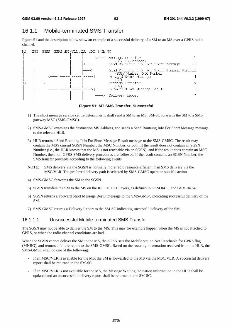
ETSI
EN 301 344 V6.3.2 (1999-07)92GSM 03.60 version 6.3.2 Release 1997
16.1.1 Mobile-terminated SMS Transfer
Figure 51 and the description below show an example of a successful delivery of a SM to an MS over a GPRS radiochannel.
06 %66 6*61 **61 06&�9/5 +/5 606�* 60�6&_ _ _ _ _ _ _ __ _ _ _ _ _ _�����_ 0HVVDJH 7UDQVIHU �_ _ _ _ _ _ _ _ �60� 06 $GGUHVV�_ _ _ _ _ _�����_ _ 6HQG 5RXWHLQJ ,QIR )RU 6KRUW 0HVVDJH �_ _ _ _ _ _ _ __ _ _ _ _ _����!_ _ 6HQG 5RXWHLQJ ,QIR )RU 6KRUW 0HVVDJH 5HVXOW�_ _ _ _ _ _ _ _ �6*61 1XPEHU� 06& 1XPEHU�_ _ _�����_�����_�����_�����_ _ )RUZDUG 6KRUW 0HVVDJH �_ _ _ _ _ _ _ _ �60�_�����_����!_ _ _ _ _ _ 0HVVDJH 7UDQVIHU �_ _ _ _ _ _ _ _ �60�_ _ _�����_�����_�����_����!_ _ )RUZDUG 6KRUW 0HVVDJH 5HVXOW �_ _ _ _ _ _ _ __ _ _ _ _ _ _����!_ 'HOLYHU\ 5HSRUW �_ _ _ _ _ _ _ _
Figure 51: MT SMS Transfer, Successful
1) The short message service centre determines it shall send a SM to an MS. SM-SC forwards the SM to a SMSgateway MSC (SMS-GMSC).
2) SMS-GMSC examines the destination MS Address, and sends a Send Routeing Info For Short Message messageto the relevant HLR.
3) HLR returns a Send Routeing Info For Short Message Result message to the SMS-GMSC. The result maycontain the MS's current SGSN Number, the MSC Number, or both. If the result does not contain an SGSNNumber (i.e., the HLR knows that the MS is not reachable via an SGSN), and if the result does contain an MSCNumber, then non-GPRS SMS delivery procedures are followed. If the result contains an SGSN Number, theSMS transfer proceeds according to the following events.
NOTE: SMS delivery via the SGSN is normally more radio resource efficient than SMS delivery via theMSC/VLR. The preferred delivery path is selected by SMS-GMSC operator-specific action.
4) SMS-GMSC forwards the SM to the SGSN.
5) SGSN transfers the SM to the MS on the RP, CP, LLC layers, as defined in GSM 04.11 and GSM 04.64.
6) SGSN returns a Forward Short Message Result message to the SMS-GMSC indicating successful delivery of theSM.
7) SMS-GMSC returns a Delivery Report to the SM-SC indicating successful delivery of the SM.
16.1.1.1 Unsuccessful Mobile-terminated SMS Transfer
The SGSN may not be able to deliver the SM to the MS. This may for example happen when the MS is not attached toGPRS, or when the radio channel conditions are bad.
When the SGSN cannot deliver the SM to the MS, the SGSN sets the Mobile station Not Reachable for GPRS flag(MNRG), and returns a failure report to the SMS-GMSC. Based on the routeing information received from the HLR, theSMS-GMSC shall do one of the following:
- If an MSC/VLR is available for the MS, the SM is forwarded to the MS via the MSC/VLR. A successful deliveryreport shall be returned to the SM-SC.
- If an MSC/VLR is not available for the MS, the Message Waiting Indication information in the HLR shall beupdated and an unsuccessful delivery report shall be returned to the SM-SC.
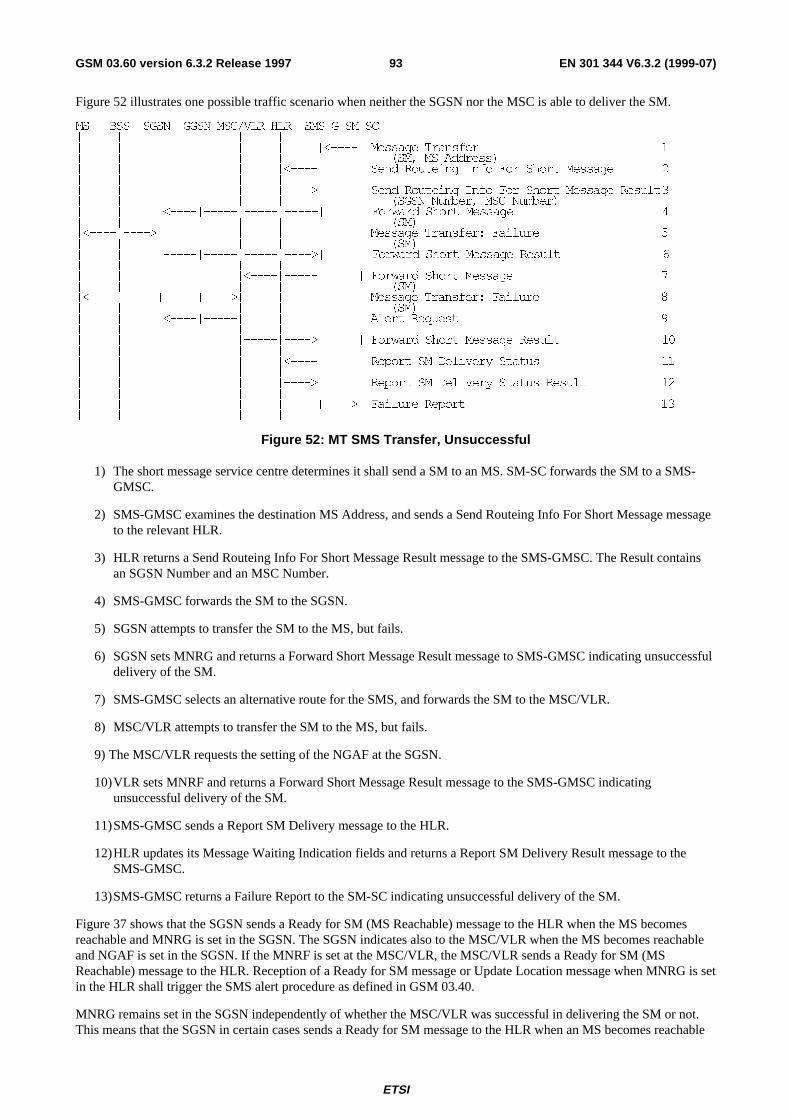
ETSI
EN 301 344 V6.3.2 (1999-07)93GSM 03.60 version 6.3.2 Release 1997
Figure 52 illustrates one possible traffic scenario when neither the SGSN nor the MSC is able to deliver the SM.
06 %66 6*61 **61 06&�9/5 +/5 606�* 60�6&_ _ _ _ _ _ _ __ _ _ _ _ _ _�����_ 0HVVDJH 7UDQVIHU �_ _ _ _ _ _ _ _ �60� 06 $GGUHVV�_ _ _ _ _ _�����_ _ 6HQG 5RXWHLQJ ,QIR )RU 6KRUW 0HVVDJH �_ _ _ _ _ _ _ __ _ _ _ _ _����!_ _ 6HQG 5RXWHLQJ ,QIR )RU 6KRUW 0HVVDJH 5HVXOW�_ _ _ _ _ _ _ _ �6*61 1XPEHU� 06& 1XPEHU�_ _ _�����_�����_�����_�����_ _ )RUZDUG 6KRUW 0HVVDJH �_ _ _ _ _ _ _ _ �60�_�����_����!_ _ _ _ _ _ 0HVVDJH 7UDQVIHU� )DLOXUH �_ _ _ _ _ _ _ _ �60�_ _ _�����_�����_�����_����!_ _ )RUZDUG 6KRUW 0HVVDJH 5HVXOW �_ _ _ _ _ _ _ __ _ _ _ _�����_�����_ _ )RUZDUG 6KRUW 0HVVDJH �_ _ _ _ _ _ _ _ �60�_�����_�����_�����_����!_ _ _ _ 0HVVDJH 7UDQVIHU� )DLOXUH �_ _ _ _ _ _ _ _ �60�_ _ _�����_�����_ _ _ _ $OHUW 5HTXHVW �_ _ _ _ _ _ _ __ _ _ _ _�����_����!_ _ )RUZDUG 6KRUW 0HVVDJH 5HVXOW ��_ _ _ _ _ _ _ __ _ _ _ _ _�����_ _ 5HSRUW 60 'HOLYHU\ 6WDWXV ��_ _ _ _ _ _ _ __ _ _ _ _ _����!_ _ 5HSRUW 60 'HOLYHU\ 6WDWXV 5HVXOW ��_ _ _ _ _ _ _ __ _ _ _ _ _ _����!_ )DLOXUH 5HSRUW ��_ _ _ _ _ _ _ _
Figure 52: MT SMS Transfer, Unsuccessful
1) The short message service centre determines it shall send a SM to an MS. SM-SC forwards the SM to a SMS-GMSC.
2) SMS-GMSC examines the destination MS Address, and sends a Send Routeing Info For Short Message messageto the relevant HLR.
3) HLR returns a Send Routeing Info For Short Message Result message to the SMS-GMSC. The Result containsan SGSN Number and an MSC Number.
4) SMS-GMSC forwards the SM to the SGSN.
5) SGSN attempts to transfer the SM to the MS, but fails.
6) SGSN sets MNRG and returns a Forward Short Message Result message to SMS-GMSC indicating unsuccessfuldelivery of the SM.
7) SMS-GMSC selects an alternative route for the SMS, and forwards the SM to the MSC/VLR.
8) MSC/VLR attempts to transfer the SM to the MS, but fails.
9) The MSC/VLR requests the setting of the NGAF at the SGSN.
10)VLR sets MNRF and returns a Forward Short Message Result message to the SMS-GMSC indicatingunsuccessful delivery of the SM.
11)SMS-GMSC sends a Report SM Delivery message to the HLR.
12)HLR updates its Message Waiting Indication fields and returns a Report SM Delivery Result message to theSMS-GMSC.
13)SMS-GMSC returns a Failure Report to the SM-SC indicating unsuccessful delivery of the SM.
Figure 37 shows that the SGSN sends a Ready for SM (MS Reachable) message to the HLR when the MS becomesreachable and MNRG is set in the SGSN. The SGSN indicates also to the MSC/VLR when the MS becomes reachableand NGAF is set in the SGSN. If the MNRF is set at the MSC/VLR, the MSC/VLR sends a Ready for SM (MSReachable) message to the HLR. Reception of a Ready for SM message or Update Location message when MNRG is setin the HLR shall trigger the SMS alert procedure as defined in GSM 03.40.
MNRG remains set in the SGSN independently of whether the MSC/VLR was successful in delivering the SM or not.This means that the SGSN in certain cases sends a Ready for SM message to the HLR when an MS becomes reachable
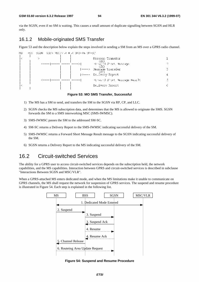
ETSI
EN 301 344 V6.3.2 (1999-07)94GSM 03.60 version 6.3.2 Release 1997
via the SGSN, even if no SM is waiting. This causes a small amount of duplicate signalling between SGSN and HLRonly.
16.1.2 Mobile-originated SMS Transfer
Figure 53 and the description below explain the steps involved in sending a SM from an MS over a GPRS radio channel.
06 %66 6*61 **61 06&�9/5 +/5 606�,: 60�6&_ _ _ _ _ _ _ __�����_����!_ _ _ _ _ _ 0HVVDJH 7UDQVIHU �_ _ _ _ _ _ _ _ �60�_ _ _�����_�����_�����_����!_ _ )RUZDUG 6KRUW 0HVVDJH �_ _ _ _ _ _ _ _ �60�_ _ _ _ _ _ _����!_ 0HVVDJH 7UDQVIHU �_ _ _ _ _ _ _ _ �60�_ _ _ _ _ _ _�����_ 'HOLYHU\ 5HSRUW �_ _ _ _ _ _ _ __ _ _�����_�����_�����_�����_ _ )RUZDUG 6KRUW 0HVVDJH 5HVXOW �_ _ _ _ _ _ _ __�����_�����_ _ _ _ _ _ 'HOLYHU\ 5HSRUW �_ _ _ _ _ _ _ _
Figure 53: MO SMS Transfer, Successful
1) The MS has a SM to send, and transfers the SM to the SGSN via RP, CP, and LLC.
2) SGSN checks the MS subscription data, and determines that the MS is allowed to originate the SMS. SGSNforwards the SM to a SMS interworking MSC (SMS-IWMSC).
3) SMS-IWMSC passes the SM to the addressed SM-SC.
4) SM-SC returns a Delivery Report to the SMS-IWMSC indicating successful delivery of the SM.
5) SMS-IWMSC returns a Forward Short Message Result message to the SGSN indicating successful delivery ofthe SM.
6) SGSN returns a Delivery Report to the MS indicating successful delivery of the SM.
16.2 Circuit-switched ServicesThe ability for a GPRS user to access circuit-switched services depends on the subscription held, the networkcapabilities, and the MS capabilities. Interaction between GPRS and circuit-switched services is described in subclause"Interactions Between SGSN and MSC/VLR".
When a GPRS-attached MS enters dedicated mode, and when the MS limitations make it unable to communicate onGPRS channels, the MS shall request the network for suspension of GPRS services. The suspend and resume procedureis illustrated in Figure 54. Each step is explained in the following list.
2. Suspend
6. Routeing Area Update Request
1. Dedicated Mode Entered
MS BSS SGSN MSC/VLR
3. Suspend
4. Resume
5. Channel Release
3. Suspend Ack
4. Resume Ack
Figure 54: Suspend and Resume Procedure
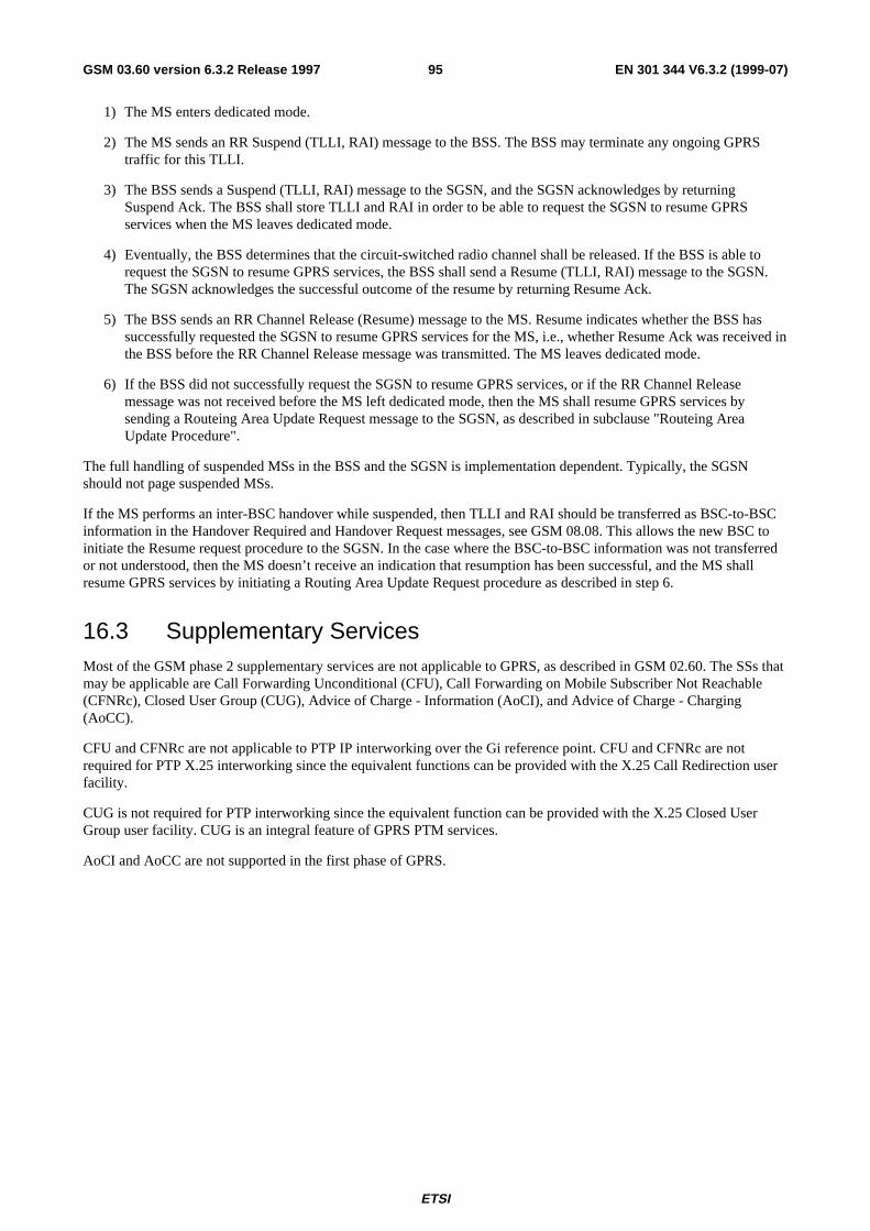
ETSI
EN 301 344 V6.3.2 (1999-07)95GSM 03.60 version 6.3.2 Release 1997
1) The MS enters dedicated mode.
2) The MS sends an RR Suspend (TLLI, RAI) message to the BSS. The BSS may terminate any ongoing GPRStraffic for this TLLI.
3) The BSS sends a Suspend (TLLI, RAI) message to the SGSN, and the SGSN acknowledges by returningSuspend Ack. The BSS shall store TLLI and RAI in order to be able to request the SGSN to resume GPRSservices when the MS leaves dedicated mode.
4) Eventually, the BSS determines that the circuit-switched radio channel shall be released. If the BSS is able torequest the SGSN to resume GPRS services, the BSS shall send a Resume (TLLI, RAI) message to the SGSN.The SGSN acknowledges the successful outcome of the resume by returning Resume Ack.
5) The BSS sends an RR Channel Release (Resume) message to the MS. Resume indicates whether the BSS hassuccessfully requested the SGSN to resume GPRS services for the MS, i.e., whether Resume Ack was received inthe BSS before the RR Channel Release message was transmitted. The MS leaves dedicated mode.
6) If the BSS did not successfully request the SGSN to resume GPRS services, or if the RR Channel Releasemessage was not received before the MS left dedicated mode, then the MS shall resume GPRS services bysending a Routeing Area Update Request message to the SGSN, as described in subclause "Routeing AreaUpdate Procedure".
The full handling of suspended MSs in the BSS and the SGSN is implementation dependent. Typically, the SGSNshould not page suspended MSs.
If the MS performs an inter-BSC handover while suspended, then TLLI and RAI should be transferred as BSC-to-BSCinformation in the Handover Required and Handover Request messages, see GSM 08.08. This allows the new BSC toinitiate the Resume request procedure to the SGSN. In the case where the BSC-to-BSC information was not transferredor not understood, then the MS doesn’t receive an indication that resumption has been successful, and the MS shallresume GPRS services by initiating a Routing Area Update Request procedure as described in step 6.
16.3 Supplementary ServicesMost of the GSM phase 2 supplementary services are not applicable to GPRS, as described in GSM 02.60. The SSs thatmay be applicable are Call Forwarding Unconditional (CFU), Call Forwarding on Mobile Subscriber Not Reachable(CFNRc), Closed User Group (CUG), Advice of Charge - Information (AoCI), and Advice of Charge - Charging(AoCC).
CFU and CFNRc are not applicable to PTP IP interworking over the Gi reference point. CFU and CFNRc are notrequired for PTP X.25 interworking since the equivalent functions can be provided with the X.25 Call Redirection userfacility.
CUG is not required for PTP interworking since the equivalent function can be provided with the X.25 Closed UserGroup user facility. CUG is an integral feature of GPRS PTM services.
AoCI and AoCC are not supported in the first phase of GPRS.
ETSI
EN 301 344 V6.3.2 (1999-07)96GSM 03.60 version 6.3.2 Release 1997
Annex A (normative):GGSN Selection Decision Tree
A.1 DefinitionsThe SGSN knows from the subscription data the parameters (S for Subscribed): PDP type (S), PDP address (S),APN (S), and VPLMN address allowed.
The SGSN may know from configuration the default APN supporting a given PDP type. This APN is calledAPN (SGSN) and does not include an APN Operator Identifier.
The SGSN knows the parameters requested by the MS (R for Requested): PDP type (R), PDP address (R), andAPN (R). APN (R) is the APN Network Identifier requested by the user.
In case of "an APN chosen by the SGSN" the activated PDP context is always linked with a dynamic PDP address.
An MS may have multiple subscription records for the same PDP type and the same PDP address, but with differentAPNs.
An MS may have one or two subscription records with the same PDP type and the same APN: one with a static PDPaddress, one with a dynamic PDP address.
When the MS is in its HPMLN, if the MS requests an APN that does not correspond to any GGSN of its HPLMN, therequest shall be rejected by SGSN. When the MS is in a VPMLN, if the MS requests an APN that does not correspondto any GGSN of its HPLMN nor of this VPLMN, the request shall be rejected by SGSN.
If APN (S) = wild card (see GSM 03.03), it means either:
- that a default APN (a default PDN) has to be chosen by the SGSN (APN (SGSN)) if no APN (R) has beenprovided; or
- that a PDP context with dynamic PDP address may be activated towards any APN requested by the MS.
A.2 APN (R)In order to derive APN (R) from the APN sent by the MS, the SGSN shall check if the APN sent by the user ends with".gprs". If not, then APN (R) is equal to APN sent by the MS. If yes, then APN (R) is the APN sent by the MS withoutthe three last labels.
A.3 APN Selection RulesThe SGSN shall select the APN to be used to derive the GGSN address, and set the selection mode parameter accordingto the following rules.
If no PDP type, no PDP address and no APN is sent by the MS, SGSN checks if there is a single PDP contextsubscription record subscribed for this subscriber
If yes, SGSN checks if a PDP address is present in the single PDP context subscription record
If yes, SGSN considers that MS requested a static PDP address, SGSN selects APN (S) from this PDPcontext subscription record and sets selection mode parameter to "subscribed", go to case 3
If no, SGSN considers that MS requested a dynamic PDP address, and checks if APN (S) is a wild card
If no, SGSN selects APN (S) and sets selection mode parameter to "subscribed", go to case 3
ETSI
EN 301 344 V6.3.2 (1999-07)97GSM 03.60 version 6.3.2 Release 1997
If yes, SGSN selects subscribed PDP type and sets selection mode parameter to "chosen by SGSN", go tocase 2
If no, SGSN rejects Activate PDP Context Request
If no PDP type, but either a PDP address, or an APN, or both is sent by MS, SGSN rejects Activate PDP ContextRequest
If PDP type (R) is sent by user, SGSN looks for PDP context subscription records where PDP type (S) = PDP type (R)
If none exists, SGSN rejects Activate PDP Context Request
If at least one exists, SGSN checks if PDP address is sent by the MS
If a PDP address is sent, SGSN selects the PDP context subscription records where PDP address (S) = PDPaddress (R)
If none exists, SGSN rejects Activate PDP Context Request
If only one record where PDP address (S) = PDP address (R) exists, SGSN checks if APN (R) is empty
If an APN (R) is not empty, check if APN (S) = APN (R)
If yes, SGSN selects APN (R) and sets selection mode parameter to "subscribed", go to case 1
If no, SGSN rejects Activate PDP Context Request
If APN (R) is empty, SGSN selects APN (S) and sets selection mode parameter to "subscribed", go tocase 3
If more than one subscription record where PDP address (S) = PDP address (R) exists
If an APN (R) is not empty, SGSN selects the subscription record where APN (S) = APN (R)
If none exists, SGSN rejects Activate PDP Context Request
If one exists, SGSN selects APN (R) and sets selection mode parameter to "subscribed", go tocase 1
If APN (R) is empty, SGSN rejects Activate PDP Context Request
If no PDP address is sent, SGSN checks APN (R)
If APN (R) not empty, SGSN checks if PDP context subscription record where APN (S) = APN (R) exists
If none exists, SGSN checks if HLR has one PDP context subscription record with APN (S) = wildcard
If yes, SGSN selects this PDP context subscription record, selects APN (R), and sets selectionmode parameter to "sent by MS", go to case 1
If no, SGSN rejects Activate PDP Context Request
If only one subscription record where APN (S) = APN (R) exists, SGSN selects this PDP contextsubscription record, selects APN (S), and sets selection mode parameter to "subscribed", and checks ifa PDP address is present in this PDP context subscription record
If a PDP address is present, SGSN considers that MS requested a static PDP address, go to case 1
If no PDP address is present, SGSN considers that MS requested a dynamic PDP address, go tocase 1
If more than one subscription record where APN (S) = APN (R) exists, SGSN selects the PDP contextsubscription that allows the dynamic adress
If one exists, SGSN selects APN (S) and sets selection mode parameter to "subscribed", go tocase 1
ETSI
EN 301 344 V6.3.2 (1999-07)98GSM 03.60 version 6.3.2 Release 1997
If none exists, SGSN rejects the Activate PDP Context Request
If APN (R) empty, check if HLR has one PDP context subscription record with APN (S) = wild card
If yes, SGSN sets selection mode parameter to "chosen by SGSN", go to case 2
If no, SGSN checks if there is a single PDP context subscription record subscribed for this PDP type
If yes, SGSN selects APN (S) from this PDP context subscription record and sets selection modeparameter to "subscribed", go to case 3
If no, SGSN rejects Activate PDP Context Request
Case 1: (an APN was sent by the MS)
SGSN checks if the APN sent by MS included an APN Operator Identifier
If yes, SGSN checks if APN Operator Identifier is in HPLMN
If yes, go to case a
If no, SGSN checks if APN Operator Identifier is in VPLMN
If yes, SGSN checks if VPLMN address allowed for this selected PDP context subscription record
If yes, go to case b
If no, SGSN rejects Activate PDP Context Request
If no, SGSN rejects Activate PDP Context Request
If no, SGSN checks if VPLMN allowed for this selected PDP context subscription record
If yes, go to case c
If no, go to case a
Case 2: (a default APN is to be chosen by SGSN)
SGSN checks if user is currently located in HPLMN
If yes, SGSN checks if it knows an APN (SGSN) supporting this PDP type
If yes, SGSN selects APN (SGSN) and go to case a
If no, SGSN rejects Activate PDP Context Request
If no, check if VPLMN allowed for the wild card subscription record
If yes, SGSN checks if it knows an APN (SGSN) supporting this PDP type
If yes, SGSN selects APN (SGSN) and go to case b
If no, SGSN rejects Activate PDP Context Request
If no, SGSN rejects Activate PDP Context Request
Case 3: (the APN from the single PDP context was selected)
SGSN checks if VPLMN address allowed for this unique subscription records
If yes, go to case c
If no, go to case a
Case a: (access requested in HPLMN)
ETSI
EN 301 344 V6.3.2 (1999-07)99GSM 03.60 version 6.3.2 Release 1997
SGSN interrogates DNS server with selected APN with appended HPLMN APN Operator Identifier to interrogate DNSserver
If interrogation fails, reject Activate PDP Context Request
If interrogation successful, SGSN sends Create PDP Context Request to GGSN
Case b: (access requested in VPLMN only)
SGSN interrogates DNS server with selected APN with appended VPLMN APN Operator Identifier to interrogate DNSserver
If interrogation fails, reject Activate PDP Context Request
If interrogation successful, SGSN sends Create PDP Context Request to GGSN
Case c: (access requested in VPLMN first)
SGSN interrogates DNS server with selected APN with appended VPLMN APN Operator Identifier to interrogate DNSserver
If interrogation fails, go to case a
If interrogation successful, SGSN sends Create PDP Context Request to GGSN.
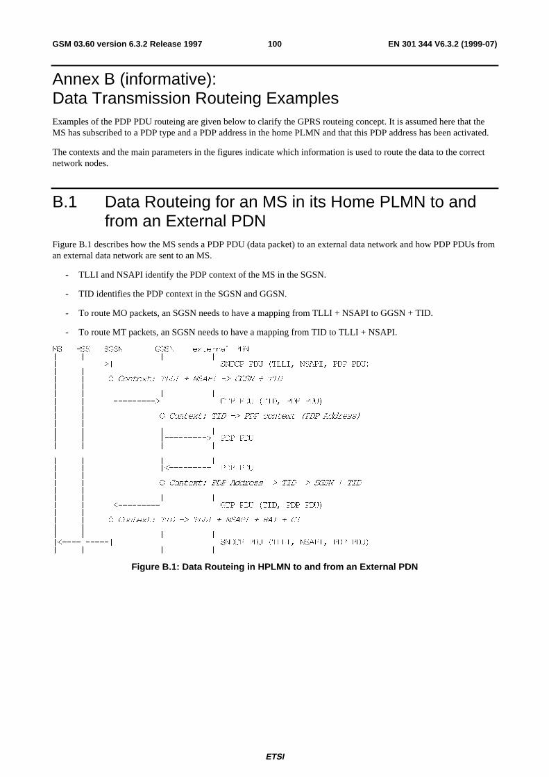
ETSI
EN 301 344 V6.3.2 (1999-07)100GSM 03.60 version 6.3.2 Release 1997
Annex B (informative):Data Transmission Routeing ExamplesExamples of the PDP PDU routeing are given below to clarify the GPRS routeing concept. It is assumed here that theMS has subscribed to a PDP type and a PDP address in the home PLMN and that this PDP address has been activated.
The contexts and the main parameters in the figures indicate which information is used to route the data to the correctnetwork nodes.
B.1 Data Routeing for an MS in its Home PLMN to andfrom an External PDN
Figure B.1 describes how the MS sends a PDP PDU (data packet) to an external data network and how PDP PDUs froman external data network are sent to an MS.
- TLLI and NSAPI identify the PDP context of the MS in the SGSN.
- TID identifies the PDP context in the SGSN and GGSN.
- To route MO packets, an SGSN needs to have a mapping from TLLI + NSAPI to GGSN + TID.
- To route MT packets, an SGSN needs to have a mapping from TID to TLLI + NSAPI.
06 %66 6*61 **61 H[WHUQDO 3'1_ _ _ _ __�����_����!_ _ _ 61'&3 3'8 �7//,� 16$3,� 3'3 3'8�_ __ _ 2 &RQWH[W� 7//, � 16$3, �! **61 � 7,'_ __ _ _ _ __ _ _���������!_ _ *73 3'8 �7,'� 3'3 3'8�_ _ __ _ _ 2 &RQWH[W� 7,' �! 3'3 FRQWH[W �3'3 $GGUHVV�_ _ __ _ _ _ __ _ _ _���������!_ 3'3 3'8_ _ _ _ _
_ _ _ _ __ _ _ _����������_ 3'3 3'8_ _ __ _ _ 2 &RQWH[W� 3'3 $GGUHVV �! 7,' �! 6*61 � 7,'_ _ __ _ _ _ __ _ _����������_ _ *73 3'8 �7,'� 3'3 3'8�_ __ _ 2 &RQWH[W� 7,' �! 7//, � 16$3, � 5$, � &,_ __ _ _ _ __�����_�����_ _ _ 61'&3 3'8 �7//,� 16$3,� 3'3 3'8�_ _ _ _ _
Figure B.1: Data Routeing in HPLMN to and from an External PDN
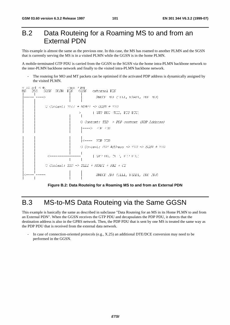
ETSI
EN 301 344 V6.3.2 (1999-07)101GSM 03.60 version 6.3.2 Release 1997
B.2 Data Routeing for a Roaming MS to and from anExternal PDN
This example is almost the same as the previous one. In this case, the MS has roamed to another PLMN and the SGSNthat is currently serving the MS is in a visited PLMN while the GGSN is in the home PLMN.
A mobile-terminated GTP PDU is carried from the GGSN to the SGSN via the home intra-PLMN backbone network tothe inter-PLMN backbone network and finally to the visited intra-PLMN backbone network.
- The routeing for MO and MT packets can be optimised if the activated PDP address is dynamically assigned bythe visited PLMN.
9LVLWHG 3/01 +RPH 3/0106 %66 6*61 **61 3'1 **61 H[WHUQDO 3'1_ _ _ _ _ _ __�����_����!_ _ _ _ _ 61'&3 3'8 �7//,� 16$3,� 3'3 3'8�_ _ _ _ _ _ __ __ _ 2 &RQWH[W� 7//, � 16$3, �! **61 � 7,'_ __ _ _����������������!_ _ *73 3'8 �7,'� 3'3 3'8�_ _ _ _ _ _ __ _ _ _ __ _ _ _ _ 2 &RQWH[W� 7,' �! 3'3 FRQWH[W �3'3 $GGUHVV�_ _ _ _ __ _ _ _ _ _����!_ 3'3 3'8_ _ _ _ _ _ _
_ _ _ _ _ _ __ _ _ _ _ _�����_ 3'3 3'8_ _ _ _ __ _ _ _ _ 2 &RQWH[W� 3'3 $GGUHVV �! 7,' �! 6*61 � 7,'_ _ _ _ __ _ _ _ _ _ __ _ _�����������������_ _ *73 3'8 �7,'� 3'3 3'8�_ _ _ _ _ _ __ __ _ 2 &RQWH[W� 7,' �! 7//, � 16$3, � 5$, � &,_ __ _ _ _ _ _ __�����_�����_ _ _ _ _ 61'&3 3'8 �7//,� 16$3,� 3'3 3'8�_ _ _ _ _ _ _
Figure B.2: Data Routeing for a Roaming MS to and from an External PDN
B.3 MS-to-MS Data Routeing via the Same GGSNThis example is basically the same as described in subclause "Data Routeing for an MS in its Home PLMN to and froman External PDN". When the GGSN receives the GTP PDU and decapsulates the PDP PDU, it detects that thedestination address is also in the GPRS network. Then, the PDP PDU that is sent by one MS is treated the same way asthe PDP PDU that is received from the external data network.
- In case of connection-oriented protocols (e.g., X.25) an additional DTE/DCE conversion may need to beperformed in the GGSN.
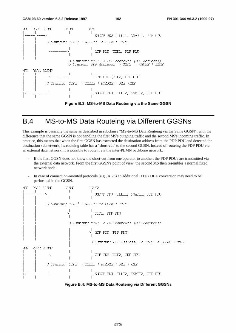
ETSI
EN 301 344 V6.3.2 (1999-07)102GSM 03.60 version 6.3.2 Release 1997
06� %66� 6*61� **61 3'1_ _ _ _ __�����_����!_ _ _ 61'&3 3'8 �7//,�� 16$3,�� 3'3 3'8�_ __ _ 2 &RQWH[W� 7//,� � 16$3,� �! **61 � 7,'�_ __ _ _ _ __ _ _���������!_ _ *73 3'8 �7,'�� 3'3 3'8�_ _ _ _ __ _ _
2 &RQWH[W� 7,'� �! 3'3 FRQWH[W� �3'3 $GGUHVV��2 &RQWH[W� 3'3 $GGUHVV� �! 7,'� �! 6*61� � 7,'�
06� %66� 6*61� _ __ _ _ _ __ _ _����������_ _ *73 3'8 �7,'�� 3'3 3'8�_ __ _ 2 &RQWH[W� 7,'� �! 7//,� � 16$3,� � 5$� �&,�_ __ _ _ _ __�����_�����_ _ _ 61'&3 3'8 �7//,�� 16$3,�� 3'3 3'8�_ _ _ _ _
Figure B.3: MS-to-MS Data Routeing via the Same GGSN
B.4 MS-to-MS Data Routeing via Different GGSNsThis example is basically the same as described in subclause "MS-to-MS Data Routeing via the Same GGSN", with thedifference that the same GGSN is not handling the first MS's outgoing traffic and the second MS's incoming traffic. Inpractice, this means that when the first GGSN has extracted the destination address from the PDP PDU and detected thedestination subnetwork, its routeing table has a "short-cut" to the second GGSN. Instead of routeing the PDP PDU viaan external data network, it is possible to route it via the inter-PLMN backbone network.
- If the first GGSN does not know the short-cut from one operator to another, the PDP PDUs are transmitted viathe external data network. From the first GGSN's point of view, the second MS then resembles a normal fixednetwork node.
- In case of connection-oriented protocols (e.g., X.25) an additional DTE / DCE conversion may need to beperformed in the GGSN.
06� %66� 6*61� **61� **61�_ _ _ _ __�����_����!_ _ _ 61'&3 3'8 �7//,�� 16$3,�� 3'3 3'8�_ _ _ _ __ __ _ 2 &RQWH[W� 7//,� � 16$3,� �! **61 � 7,'�_ __ _ _ _ __ _ _���������!_ _ 7,'�� 3'3 3'8_ _ _ _ __ _ __ _ _ 2 &RQWH[W� 7,'� �! 3'3 FRQWH[W� �3'3 $GGUHVV��_ _ __ _ _ _ __ _ _ _���������!_ *73 3'8 �3'3 3'8�_ _ _ _ __ _ _ _
_ 2 &RQWH[W� 3'3 $GGUHVV� �! 7,'� �! 6*61� � 7,'�_
06� %66� 6*61� _ __ _ _ _ __ _ _���������������������_ *73 3'8 �7,'�� 3'3 3'8�_ _ _ _ __ __ _ 2 &RQWH[W� 7,'� �! 7//,� � 16$3,� � 5$� � &,�_ __ _ _ _ __�����_�����_ _ _ 61'&3 3'8 �7//,�� 16$3,�� 3'3 3'8�_ _ _ _ _
Figure B.4: MS-to-MS Data Routeing via Different GGSNs
ETSI
EN 301 344 V6.3.2 (1999-07)103GSM 03.60 version 6.3.2 Release 1997
Annex C (informative):FiguresFigure 1: GPRS Access Interfaces and Reference Points ................................................................................................. 14
Figure 2: Overview of the GPRS Logical Architecture .................................................................................................... 19
Figure 3: Intra- and Inter-PLMN Backbone Networks ..................................................................................................... 20
Figure 4: Transmission Plane............................................................................................................................................ 22
Figure 5: Signalling Plane MS - SGSN............................................................................................................................. 23
Figure 6: Signalling Plane SGSN - HLR .......................................................................................................................... 23
Figure 7: Signalling Plane SGSN - MSC/VLR................................................................................................................. 24
Figure 8: Signalling Plane SGSN - SMS-GMSC and SGSN - SMS-IWMSC .................................................................. 24
Figure 9: Signalling Plane GSN - GSN............................................................................................................................. 25
Figure 10: Signalling Plane GGSN - HLR Using MAP.................................................................................................... 25
Figure 11: Signalling Plane GGSN - HLR Using GTP and MAP..................................................................................... 26
Figure 12: Functional Mobility Management State Model ............................................................................................... 28
Figure 13: Functional Anonymous Access Mobility Management State Model............................................................... 29
Figure 14: CS Paging Procedure....................................................................................................................................... 33
Figure 15: MS Information Procedure.............................................................................................................................. 35
Figure 16: MM information Procedure............................................................................................................................. 35
Figure 17: Combined GPRS / IMSI Attach Procedure ..................................................................................................... 37
Figure 18: MS-Initiated Combined GPRS / IMSI Detach Procedure ............................................................................... 40
Figure 19: SGSN-Initiated GPRS Detach Procedure........................................................................................................ 40
Figure 20: HLR-Initiated GPRS Detach Procedure .......................................................................................................... 41
Figure 21: Purge Procedure .............................................................................................................................................. 42
Figure 22: Authentication Procedure ................................................................................................................................ 42
Figure 23: P-TMSI Reallocation Procedure ..................................................................................................................... 43
Figure 24: Scope of GPRS Ciphering............................................................................................................................... 44
Figure 25: Identity Check Procedure ................................................................................................................................ 44
Figure 26: Intra SGSN Routeing Area Update Procedure ................................................................................................ 46
Figure 27: Inter SGSN Routeing Area Update Procedure ................................................................................................ 47
Figure 28: Combined RA / LA Update in the Case of Intra SGSN RA Update Procedure...............................................49
Figure 29: Combined RA / LA Update in the Case of Inter SGSN RA Update Procedure...............................................51
Figure 30: Insert Subscriber Data Procedure .................................................................................................................... 54
Figure 31: Delete Subscriber Data Procedure................................................................................................................... 55
Figure 32: GPRS Paging Procedure.................................................................................................................................. 58
ETSI
EN 301 344 V6.3.2 (1999-07)104GSM 03.60 version 6.3.2 Release 1997
Figure 33: Functional PDP State Model ........................................................................................................................... 59
Figure 34: PDP Context Activation Procedure ................................................................................................................. 60
Figure 35: Successful Network-Requested PDP Context Activation Procedure............................................................... 62
Figure 36: Protection Procedure ....................................................................................................................................... 63
Figure 37: Mobile User Activity Procedure...................................................................................................................... 64
Figure 38: Anonymous Access PDP Context Activation Procedure................................................................................. 65
Figure 39: PDP Context Modification Procedure ............................................................................................................. 66
Figure 40: PDP Context Deactivation Initiated by MS Procedure.................................................................................... 67
Figure 41: PDP Context Deactivation Initiated by SGSN Procedure ............................................................................... 67
Figure 42: PDP Context Deactivation Initiated by GGSN Procedure............................................................................... 68
Figure 43: Anonymous Access PDP Context Deactivation Initiated by MS Procedure ................................................... 68
Figure 44: Anonymous Access PDP Context Deactivation Initiated by GGSN Procedure .............................................. 69
Figure 45: Multiplexing of Network Protocols ................................................................................................................. 73
Figure 46: Sequential Invocation of SNDC Functionality ................................................................................................ 74
Figure 47: BSSGP Protocol Position................................................................................................................................ 75
Figure 48: Remote Packet Control Unit (PCU) Positions................................................................................................. 77
Figure 49: GPRS Subscription Data ................................................................................................................................. 78
Figure 50: Use of NSAPI and TLLI ................................................................................................................................. 85
Figure 51: MT SMS Transfer, Successful ........................................................................................................................ 92
Figure 52: MT SMS Transfer, Unsuccessful .................................................................................................................... 93
Figure 53: MO SMS Transfer, Successful ........................................................................................................................ 94
Figure 54: Suspend and Resume Procedure...................................................................................................................... 94
ETSI
EN 301 344 V6.3.2 (1999-07)105GSM 03.60 version 6.3.2 Release 1997
Annex D (informative):TablesTable 1: Mapping of Functions to Logical Architecture................................................................................................... 21
Table 2: Network Operation Modes ................................................................................................................................. 34
Table 3: Mapping of High-level Functions Across the Gb Architecture........................................................................... 76
Table 4: HLR GPRS Subscription Data............................................................................................................................ 79
Table 5: SGSN MM and PDP Contexts............................................................................................................................ 80
Table 6: SGSN MM and PDP Contexts for Anonymous Access...................................................................................... 81
Table 7: GGSN PDP Context ........................................................................................................................................... 81
Table 8: GGSN PDP Context for Anonymous Access ..................................................................................................... 82
Table 9: MS MM and PDP Contexts ................................................................................................................................ 82
Table 10: MS MM and PDP Contexts for Anonymous Access ........................................................................................ 83
Table 11: MSC/VLR Association..................................................................................................................................... 83
Table 12: Precedence Classes........................................................................................................................................... 89
Table 13: Reliability Classes ............................................................................................................................................ 89
Table 14: Peak Throughput Classes.................................................................................................................................. 90
Table 15: Mean Throughput Classes ................................................................................................................................ 91
ETSI
EN 301 344 V6.3.2 (1999-07)106GSM 03.60 version 6.3.2 Release 1997
Annex E (informative):Document history
Document history
5.0.0 June 1997 SMG#22 approved.
5.1.0 October 1997 Included SMG#23 approved change requests A001 through A010.
5.2.0 December 1997 Included SMG#24 approved change requests A011 through A019, A021 throughA026, A028, A030 through A033, and A035.
5.3.0 March 1998 Included SMG#25 approved change requests A027, A036 through A038, A040,A042, and A043.
6.0.0 March 1998 Included SMG#25 approved change request A044.
6.1.0 June 1998 Included SMG#26 approved change requests A045 through A048, A050 throughA055, and A057 through A062.
6.1.1 August 1998 ETSI version change due to change of Public Enquiry dates.
6.2.0 October 1998 Included SMG#27 approved change requests A065, A066, A068 through A080,A082, A088, and A090.
6.3.0 February 1999 Included SMG#28 approved change requests A092, A093, A095 through A098,A100 through A102, A105, and A108.
6.3.1 April 1999 Editorial correction
6.3.2 June 1999 ETSI version change for publication
ETSI
EN 301 344 V6.3.2 (1999-07)107GSM 03.60 version 6.3.2 Release 1997
History
Document history
V6.1.1 August 1998 Public Enquiry PE 9849: 1998-08-07 to 1998-12-04
V6.3.1 April 1999 Vote V 9924: 1999-04-13 to 1999-06-11
V6.3.2 July 1999 Publication
ISBN 2-7437-2968-6Dépôt légal : Juillet 1999