GENERAL NOTES Match Deck Joint width
6
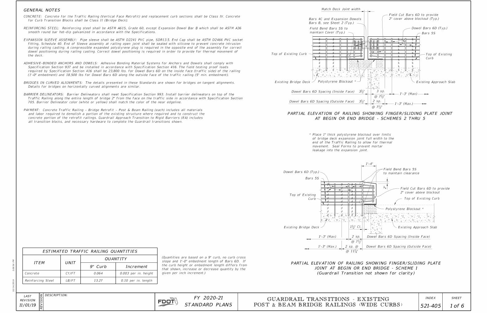
Concrete Reinforcing Steel CY/FT 0.064 13.27 0.003 per in. height 0.10 per in. length 2 sp. @ 2 sp. Dowel Bars 6D Spacing (Inside Face) Dowel Bars 6D Spacing (Outside Face) 1'-3" (Max) 1'-3" (Max.) Bars 5S Dowel Bars 6D (Typ.) 2 " Top of Existing Curb Polystyrene Blockout * * Place 1" thick polystyrene blockout over limits of bridge deck expansion joint full width to the end of the Traffic Railing to allow for thermal movement. Seal Forms to prevent mortar leakage into the expansion joint. 2 sp. 1'-3" (Max.) 1'-3" (Max) 3 sp. Dowel Bars 6D Spacing (Outside Face) Dowel Bars 6D Spacing (Inside Face) Polystyrene Blockout * Top of Existing Curb Top of Existing Curb Field Bend Bars 5S to maintain Cover (Typ.) Bars 4C and Expansion Dowels Bars B, see Sheet 2 (Typ.) Match Deck Joint width Field Cut Bars 6D to provide 2" cover above blockout (Typ.) Dowel Bars 6D (Typ.) Bars 5S 3ƀ" 3ƀ" @ 7ƀ" @ 7ƀ" Increment 9" Curb UNIT QUANTITY ESTIMATED TRAFFIC RAILING QUANTITIES ITEM LB/FT (Quantities are based on a 9" curb, no curb cross slope and 1'-0" embedment length of Bars 6D. If the curb height or embedment length differs from that shown, increase or decrease quantity by the given per inch increment.) GENERAL NOTES Top of Existing Curb Field Bend Bars 5S to maintain clearance Field Cut Bars 6D to provide 2" cover above blockout 1ƀ" Cl. @ 7ƀ" @ 11Ɓ" Existing Approach Slab Existing Bridge Deck PARTIAL ELEVATION OF RAILING SHOWING FINGER/SLIDING PLATE JOINT AT BEGIN OR END BRIDGE - SCHEME 1 (Guardrail Transition not shown for clarity) Existing Approach Slab Existing Bridge Deck PARTIAL ELEVATION OF RAILING SHOWING FINGER/SLIDING PLATE JOINT AT BEGIN OR END BRIDGE - SCHEMES 2 THRU 5 1'-4" CONCRETE: Concrete for the Traffic Railing (Vertical Face Retrofit) and replacement curb sections shall be Class IV. Concrete for Curb Transition Blocks shall be Class II (Bridge Deck). REINFORCING STEEL: Reinforcing steel shall be ASTM A615, Grade 60, except Expansion Dowel Bar B which shall be ASTM A36 smooth round bar hot-dip galvanized in accordance with the Specifications. EXPANSION SLEEVE ASSEMBLY: Pipe sleeve shall be ASTM D2241 PVC pipe, SDR13.5. End Cap shall be ASTM D2466 PVC socket fitting, Schedule 40. End of Sleeve assembly at railing open joint shall be sealed with silicone to prevent concrete intrusion during railing casting. A compressible expanded polystyrene plug is required in the opposite end of the assembly for correct dowel positioning during railing casting. Correct dowel positioning is required in order to provide for thermal movement of the deck. ADHESIVE-BONDED ANCHORS AND DOWELS: Adhesive Bonding Material Systems for Anchors and Dowels shall comply with Specification Section 937 and be installed in accordance with Specification Section 416. The field testing proof loads required by Specification Section 416 shall be 23,800 lbs. for Dowel Bars 6D on the inside face (traffic side) of the railing (1'-0" embedment) and 18,500 lbs for Dowel Bars 6D along the outside face of the traffic railing (5" min. embedment). BRIDGES ON CURVED ALIGNMENTS: The details presented in these Standards are shown for bridges on tangent alignments. Details for bridges on horizontally curved alignments are similar. BARRIER DELINEATORS: Barrier Delineators shall meet Specification Section 993. Install barrier delineators on top of the Traffic Railing along the entire length of bridge 2" from the face on the traffic side in accordance with Specification Section 705. Barrier Delineator color (white or yellow) shall match the color of the near edgeline. PAYMENT: Concrete Traffic Railing - Bridge Retrofit - Post & Beam Railing (each) includes all materials and labor required to demolish a portion of the existing structure where required and to construct the concrete portion of the retrofit railings. Guardrail Approach Transition to Rigid Barriers (EA) includes all transition blocks, and necessary hardware to complete the Guardrail transitions shown. 10/ 14/ 2019 3: 08: 56 PM REVI SI ON DESCRIPTION: REVISION LAST of STANDARD PLANS FY 2020-21 SHEET INDEX GUARDRAIL TRANSITIONS - EXISTING POST & BEAM BRIDGE RAILINGS (WIDE CURBS) 1 6 521-405 11/01/19
Transcript of GENERAL NOTES Match Deck Joint width
Concrete
Reinforcing Steel
CY/FT 0.064
13.27
0.003 per in. height
0.10 per in. length
2 sp. @
2 sp. Dowel Bars 6D Spacing (Inside Face)
Dowel Bars 6D Spacing (Outside Face)
1'-3" (Max)
1'-3" (Max.)
Bars 5S
Dowel Bars 6D (Typ.)
2"
Top of Existing Curb
Polystyrene Blockout *
* Place 1" thick polystyrene blockout over limits
of bridge deck expansion joint full width to the
end of the Traffic Railing to allow for thermal
movement. Seal Forms to prevent mortar
leakage into the expansion joint.
2 sp.1'-3" (Max.)
1'-3" (Max)3 sp.
Dowel Bars 6D Spacing (Outside Face)
Dowel Bars 6D Spacing (Inside Face)
Polystyrene Blockout *
Top of Existing
Curb
Top of Existing Curb
Field Bend Bars 5S to
maintain Cover (Typ.)
Bars 4C and Expansion Dowels
Bars B, see Sheet 2 (Typ.)
Match Deck Joint width
Field Cut Bars 6D to provide
2" cover above blockout (Typ.)
Dowel Bars 6D (Typ.)
Bars 5S
3ƀ"
3ƀ"
@ 7ƀ"
@ 7ƀ"
Increment9" CurbUNIT
QUANTITY
ESTIMATED TRAFFIC RAILING QUANTITIES
ITEM
LB/FT
(Quantities are based on a 9" curb, no curb cross
slope and 1'-0" embedment length of Bars 6D. If
the curb height or embedment length differs from
that shown, increase or decrease quantity by the
given per inch increment.)
GENERAL NOTES
Top of Existing
Curb
Field Bend Bars 5S
to maintain clearance
Field Cut Bars 6D to provide
2" cover above blockout
1ƀ" Cl.
@ 7ƀ"
@ 11Ɓ"
Existing Approach SlabExisting Bridge Deck
PARTIAL ELEVATION OF RAILING SHOWING FINGER/SLIDING PLATE
JOINT AT BEGIN OR END BRIDGE - SCHEME 1
(Guardrail Transition not shown for clarity)
Existing Approach SlabExisting Bridge Deck
PARTIAL ELEVATION OF RAILING SHOWING FINGER/SLIDING PLATE JOINT
AT BEGIN OR END BRIDGE - SCHEMES 2 THRU 5
1'-4"
CONCRETE: Concrete for the Traffic Railing (Vertical Face Retrofit) and replacement curb sections shall be Class IV. Concrete
for Curb Transition Blocks shall be Class II (Bridge Deck).
REINFORCING STEEL: Reinforcing steel shall be ASTM A615, Grade 60, except Expansion Dowel Bar B which shall be ASTM A36
smooth round bar hot-dip galvanized in accordance with the Specifications.
EXPANSION SLEEVE ASSEMBLY: Pipe sleeve shall be ASTM D2241 PVC pipe, SDR13.5. End Cap shall be ASTM D2466 PVC socket
fitting, Schedule 40. End of Sleeve assembly at railing open joint shall be sealed with silicone to prevent concrete intrusion
during railing casting. A compressible expanded polystyrene plug is required in the opposite end of the assembly for correct
dowel positioning during railing casting. Correct dowel positioning is required in order to provide for thermal movement of
the deck.
ADHESIVE-BONDED ANCHORS AND DOWELS: Adhesive Bonding Material Systems for Anchors and Dowels shall comply with
Specification Section 937 and be installed in accordance with Specification Section 416. The field testing proof loads
required by Specification Section 416 shall be 23,800 lbs. for Dowel Bars 6D on the inside face (traffic side) of the railing
(1'-0" embedment) and 18,500 lbs for Dowel Bars 6D along the outside face of the traffic railing (5" min. embedment).
BRIDGES ON CURVED ALIGNMENTS: The details presented in these Standards are shown for bridges on tangent alignments.
Details for bridges on horizontally curved alignments are similar.
BARRIER DELINEATORS: Barrier Delineators shall meet Specification Section 993. Install barrier delineators on top of the
Traffic Railing along the entire length of bridge 2" from the face on the traffic side in accordance with Specification Section
705. Barrier Delineator color (white or yellow) shall match the color of the near edgeline.
PAYMENT: Concrete Traffic Railing - Bridge Retrofit - Post & Beam Railing (each) includes all materials
and labor required to demolish a portion of the existing structure where required and to construct the
concrete portion of the retrofit railings. Guardrail Approach Transition to Rigid Barriers (EA) includes
all transition blocks, and necessary hardware to complete the Guardrail transitions shown.
10/14/2019
3:0
8:5
6 P
M
RE
VISIO
N DESCRIPTION:
REVISION
LAST
ofSTANDARD PLANS
FY 2020-21 SHEETINDEX GUARDRAIL TRANSITIONS - EXISTING
POST & BEAM BRIDGE RAILINGS (WIDE CURBS)
1 6 521-40511/01/19
Deck
Joint
2" Co
ver (T
yp.)
Existing
Approach
Slab
2 equal sp.1'-3" sp. (Typ.)Gutter Line
Joint
Deck
Bars 6
D
Gutter
LineEmbedment
1'-0"
Field Cut 2 ~ Bars 6D
2" above existing curb
for corner overhangs
Expansion
Dowel Bar B
Vertical Face
Retrofit Railing
Bars 6D
(Typ.) *
Bars 5S
(Typ.)
Vertical Face
Retrofit Railing
1'-0"2" Cover
(Typ.)
Match width of Deck Joint
Expansion Dowel Bar B
Embedment
1'-0" 1'-0"
Expansion
Dowel Sleeve
Assembly
Bars 6D @ 1'-3" Spacing
Max. (Back Face, Approach
Slab Side only)
Bars 6D @ 7ƀ" Spacing
Max. (Front Face, Approach
Slab Side only)Ø
3ƀ"
(11Ɓ" Max.)
7ƀ"7ƀ"
2 equal spaces (7ƀ" Max. on
Approach Slab, 1'-3" Max. on Bridge)
7ƀ" or 1'-3" spacing (Typ.) **
Ø
3ƀ" (T
yp.)
Pairs of Bars 4C
@ 3Ƃ " sp. (Typ.)
Shift to clear Bars
6D as required
ƀ" Preformed
Joint Filler
Pairs of Bars 4C @ 3Ƃ"
sp. (Typ.) Shift to clear
Bars 6D as required
3ƀ"
Hole Diameter to meet
Manufacturer's Requirements
Existing
Concrete
Em
bed
ment Length
Varie
s
Varie
s
Adhesive Bonding
Material SystemDowel Bar 6D,
4L or 4N
Top of Existing
Curb
Spacing Pairs of Bars 4C
Spacing Expansion
Dowel Bars B
1'-0" 1'-0"
1'-0"
Expansion Sleeve Assembly
Length of Expanded Polystyrene
Plug to match width of open joint
1" Ø PVC Pipe Sleeve,
Cap & Polystyrene Plug
2 sp. @ 3Ƃ"
2ƀ" (Shift Bars 4C
to clear Bars 6D for
skewed joints)
7ƀ"
5Ƅ
"
Ƃ" Int. Open Joint
or Deck Joint
Ɓ"
9"
3'-8"Bar 4L
Bar 4M
Bar 4N 2'-0"
3'-10"
Length as Required
3
2 & 5
1, 2 & 3
2 & 3
1 & 3
1 & 3
1 & 3
2, 3 & 4
AS REQD.
2'-0"
2'-0"
AS REQD.
4'-1"
4'-3"
2'-5"
AS REQD.5
4
4
4
6
4
4A
B
C
D
L
M
N
S
1" Ø
D = 4ƀ" Pin
5ƀ"
4ƀ"
SKEW DETAIL
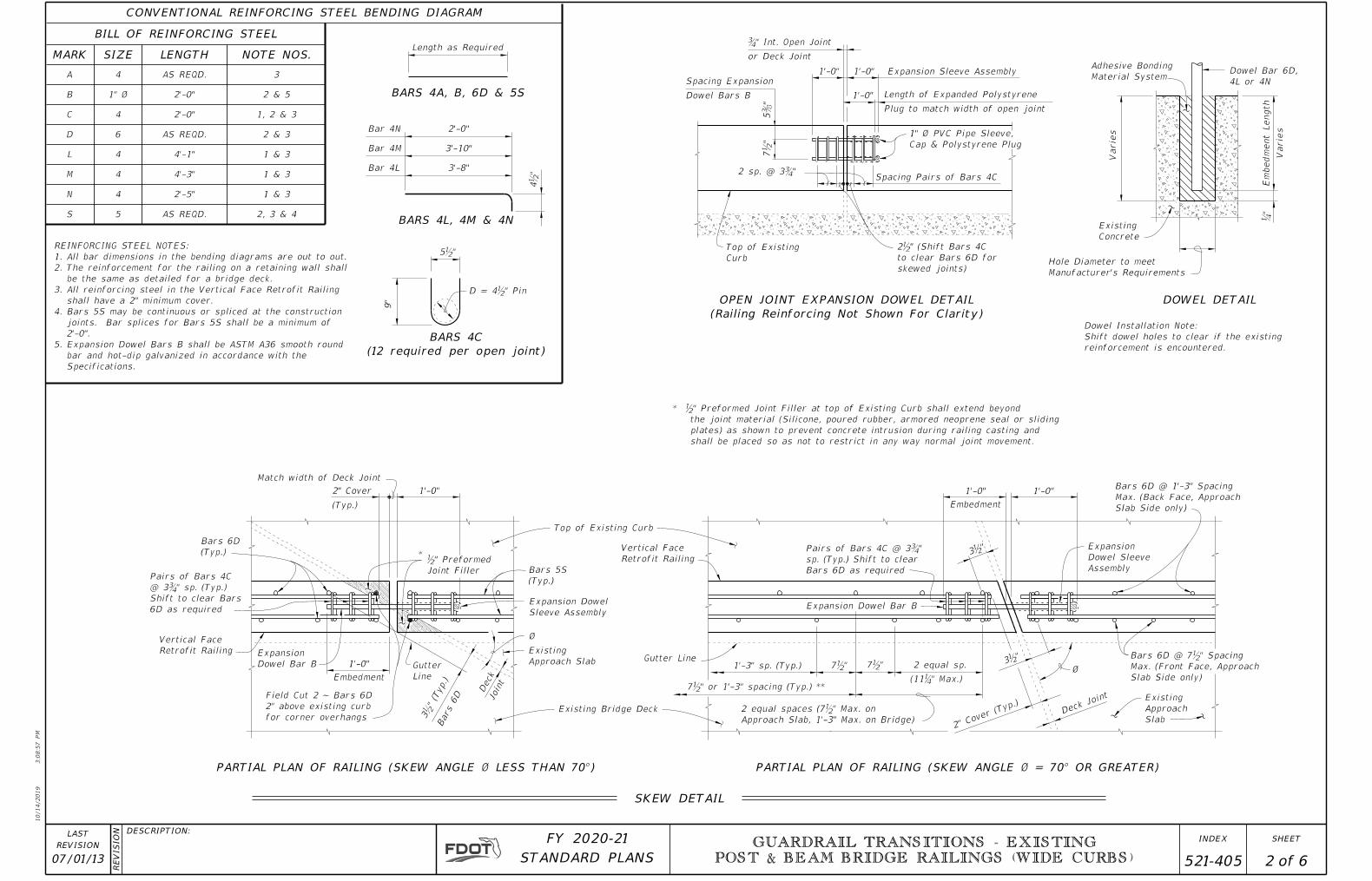
DOWEL DETAILOPEN JOINT EXPANSION DOWEL DETAIL
(Railing Reinforcing Not Shown For Clarity)
BARS 4C
(12 required per open joint)
BARS 4L, 4M & 4N
CONVENTIONAL REINFORCING STEEL BENDING DIAGRAM
BILL OF REINFORCING STEEL
NOTE NOS.LENGTHSIZEMARK
BARS 4A, B, 6D & 5S
REINFORCING STEEL NOTES:
1.All bar dimensions in the bending diagrams are out to out.
2.The reinforcement for the railing on a retaining wall shall
be the same as detailed for a bridge deck.
3.All reinforcing steel in the Vertical Face Retrofit Railing
shall have a 2" minimum cover.
4.Bars 5S may be continuous or spliced at the construction
joints. Bar splices for Bars 5S shall be a minimum of
2'-0".
5.Expansion Dowel Bars B shall be ASTM A36 smooth round
bar and hot-dip galvanized in accordance with the
Specifications.
* ƀ" Preformed Joint Filler at top of Existing Curb shall extend beyond
the joint material (Silicone, poured rubber, armored neoprene seal or sliding
plates) as shown to prevent concrete intrusion during railing casting and
shall be placed so as not to restrict in any way normal joint movement.
Dowel Installation Note:
Shift dowel holes to clear if the existing
reinforcement is encountered.
PARTIAL PLAN OF RAILING (SKEW ANGLE Ø LESS THAN 70°) PARTIAL PLAN OF RAILING (SKEW ANGLE Ø = 70° OR GREATER)
Top of Existing Curb
Existing Bridge Deck
Expansion Dowel
Sleeve Assembly
Approach Slab
Existing
10/14/2019
3:0
8:5
7 P
M
RE
VISIO
N DESCRIPTION:
REVISION
LAST
ofSTANDARD PLANS
FY 2020-21 SHEETINDEX GUARDRAIL TRANSITIONS - EXISTING
POST & BEAM BRIDGE RAILINGS (WIDE CURBS)
07/01/13 2 6 521-405
10/14/2019
3:0
8:5
8 P
M
RE
VISIO
N DESCRIPTION:
REVISION
LAST
ofSTANDARD PLANS
FY 2020-21 SHEETINDEX GUARDRAIL TRANSITIONS - EXISTING
POST & BEAM BRIDGE RAILINGS (WIDE CURBS)
07/01/13 3 6 521-405
Brid
ge
Deck
Dowel
Bars 6D
Bars 5S
(Typ.)
Dowel
Bars 6D
Final
Riding
Surface5" Min.
Embed.
� Thrie-Beam
Guardrail Bolts
� Thrie-Beam
Guardrail Bolts
SECTION A-A
TYPICAL SECTION THRU RAILING ON BRIDGE DECK
Bars 5S
(Typ.)
Existing Curb
Bridge Deck
Existing
Existing Bridge Deck
Existing Curb
Retrofit Railing
Vertical Face
Existing Bridge Deck
Varies, 7'-0" Max.
Existing Post Spacing
2" Min. Clear
1" (Min.)
3" (M
ax.) Preferred
PARTIAL ELEVATION OF INSIDE FACE OF RAILING
(Expansion Dowel Assemblies & Bars 4C not shown for clarity)
Front Face of Backwall, Begin
or End Bridge & Match Line
(See Sheets 4, 5 or 6)
Existing Bridge Coping
and cast concrete below Rail.
between 2nd & 3rd or 3rd & 4th Existing Post
Set Form flush with back of Existing Railing
(Schemes 2 thru 5 only)
Expansion Dowel
Existing Curb
Top of
3rd or 4th Existing Post
Railing
Post & Beam
Existing
Existing Post
3rd or 4th
2nd or 3rd Existing Post
1st Existing Post
2nd or 3rd Existing Post
(Type Varies)
Existing Wing Post
Existing Approach Slab Existing Wing Wall
Wall (6" Min. thickness)
with Approach Slab or Wing
Reinforced Curb Integral
Existing Bridge Deck
SECTION B-B
Beam Railing
Existing Post &
Existing Railing
back face of
Form at
2" clear of
Field Cut to
Bars 5S
Existing Railing
front face of
2" clear at
Field cut to
Bars 5S
Curb
Existing
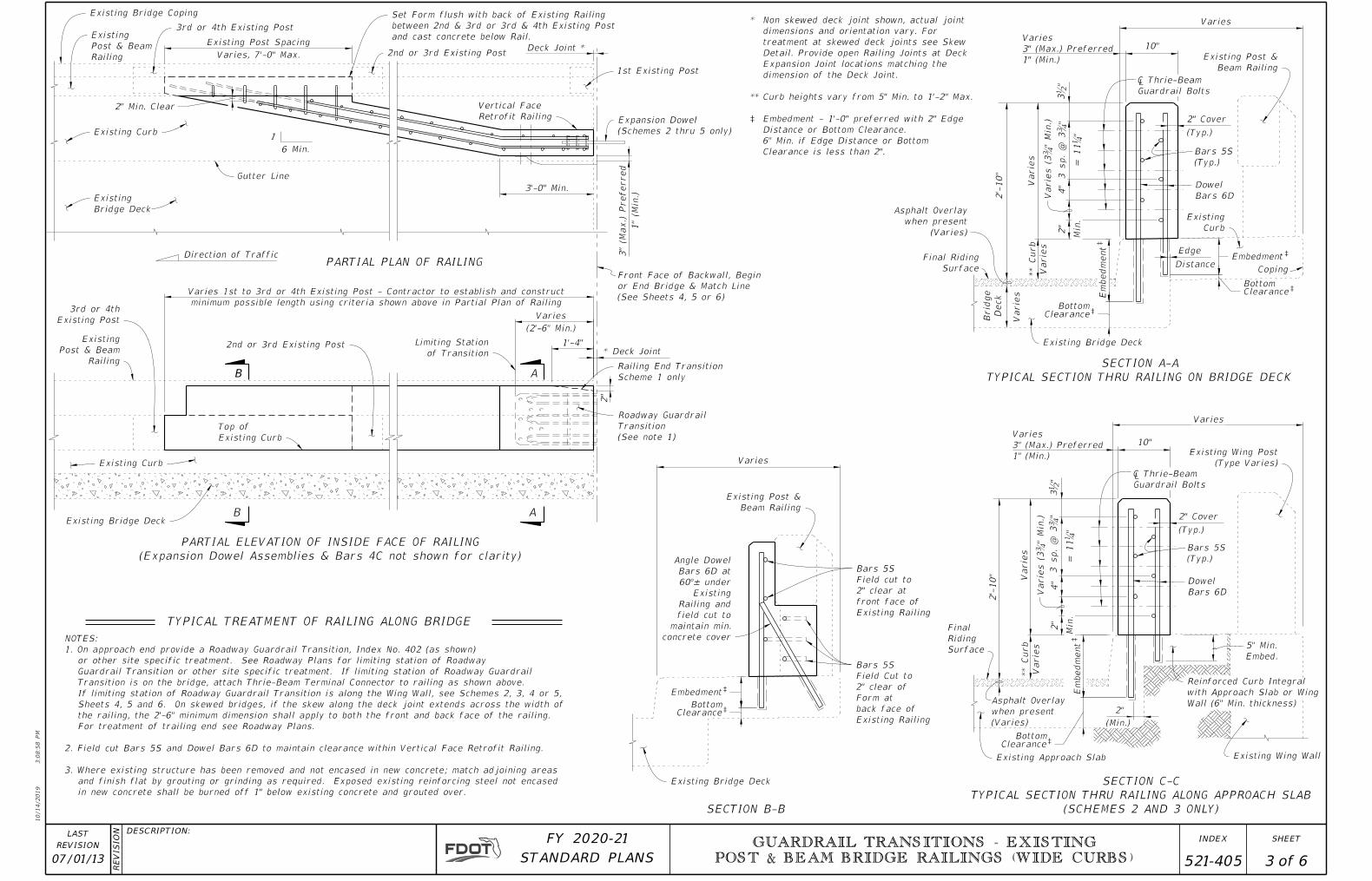
* Non skewed deck joint shown, actual joint
dimensions and orientation vary. For
treatment at skewed deck joints see Skew
Detail. Provide open Railing Joints at Deck
Expansion Joint locations matching the
dimension of the Deck Joint.
** Curb heights vary from 5" Min. to 1'-2" Max.
‡ Embedment - 1'-0" preferred with 2" Edge
Distance or Bottom Clearance.
6" Min. if Edge Distance or Bottom
Clearance is less than 2".
Asphalt Overlay
when present
(Varies)
SECTION C-C
TYPICAL SECTION THRU RAILING ALONG APPROACH SLAB
(SCHEMES 2 AND 3 ONLY)
NOTES:
1. On approach end provide a Roadway Guardrail Transition, Index No. 402 (as shown)
or other site specific treatment. See Roadway Plans for limiting station of Roadway
Guardrail Transition or other site specific treatment. If limiting station of Roadway Guardrail
Transition is on the bridge, attach Thrie-Beam Terminal Connector to railing as shown above.
If limiting station of Roadway Guardrail Transition is along the Wing Wall, see Schemes 2, 3, 4 or 5,
Sheets 4, 5 and 6. On skewed bridges, if the skew along the deck joint extends across the width of
the railing, the 2'-6" minimum dimension shall apply to both the front and back face of the railing.
For treatment of trailing end see Roadway Plans.
2. Field cut Bars 5S and Dowel Bars 6D to maintain clearance within Vertical Face Retrofit Railing.
3. Where existing structure has been removed and not encased in new concrete; match adjoining areas
and finish flat by grouting or grinding as required. Exposed existing reinforcing steel not encased
in new concrete shall be burned off 1" below existing concrete and grouted over.
(See note 1)
Transition
Roadway Guardrail
Clearance
Em
bed
ment
Clearance
Embedment
Beam Railing
Existing Post &
Clearance
Em
bed
ment
Clearance
Embedment
Asphalt Overlay
when present
(Varies)
Final Riding
Surface
3'-0" Min.
(2'-6" Min.)
Varies
2"
1'-4"
Scheme 1 only
Railing End Transition
Deck Joint *
Gutter Line
Direction of Traffic
* Deck Joint
Varies
10"
4"V
arie
s
2'-
10"
Varie
s
2"
Min.
2" Cover
(Typ.)
Coping
Edge
Distance
Varies
10"
2" Cover
Min.
2"
4"
Varie
s
2'-
10"
2"
(Min.)
Varie
s (3
Ƃ"
Min.)
3 sp.
@ 3
Ƃ"
= 11
Ɓ"
3ƀ"
(Typ.)
Varie
s (3
Ƃ"
Min.)
3 sp.
@ 3
Ƃ"
= 11
Ɓ"
3ƀ"
PARTIAL PLAN OF RAILING
TYPICAL TREATMENT OF RAILING ALONG BRIDGE
A
A
** Curb
Varie
s
** Curb
Varie
s
1
6 Min.
Railing
Post & Beam
Existing
Varies 1st to 3rd or 4th Existing Post - Contractor to establish and construct
minimum possible length using criteria shown above in Partial Plan of Railing
Varies
concrete cover
maintain min.
field cut to
Railing and
Existing
60°± under
Bars 6D at
Angle Dowel
Varies
3" (Max.) Preferred
1" (Min.)
Varies
3" (Max.) Preferred
1" (Min.)
B
B
Bottom
Bottom
Bottom
Bottom
‡
‡
‡
‡
‡
‡
‡
‡
of Transition
Limiting Station
Dowel Bars 4L (10" Embedment) (Place 3 Bars
Min. Top and 1 Bar Min. Bottom)
Existing Approach Slab
Match Existing
Curb Height
1'-0"
Transition Block
(See Note 2)
Railing End Transition
(See Note 2)
2"
1'-4"
(2'-6" Min.)
VariesLimiting Station
of Transition
Existing
Curb
Final Riding
Surface
Asphalt Overlay when
present (Varies)
of Existing Curb)
Varies (Match Length
Block (See Note 2)
3'-0" Transition
Bars 5S
(Typ.) Transition Block
(See Note 2)
Existing Approach
Slab
Direction of Traffic
7"
Edge of Existing Approach
Slab (Location Varies)Dowel Bars 6D @ 1'-3" Spacing
Max. (Back Face only)
312"(Typ. each
end)
Expansion Dowel
Sleeve Assembly
Bars 4C
(Typ.)
Vertical Face
Retrofit Railing
Existing Curb
Existing Wing Post (Type Varies)
Existing Parallel Wing Wall shown,
Existing Flared Wing Wall similarExisting Wing Post
(Type Varies)
Existing Perpendicular Wing Wall shown,
Existing Angled Wing Wall similar
Dowel Bars 4L (10" Embedment)
(See Note 2)
Edge of Existing Approach
Slab (Location Varies)
7"
Transition Block
(See Note 1)
Existing Approach SlabTransition Block
(See Note 1)
3'-0"
Direction of Traffic
Dowel Bars 4L (10" Embedment)
(See Note 2)
Transition Block
(See Note 1)
1'-0"
Match Existing
Curb Height
Existing Approach Slab
Place first post 2"
clear of Wing Wall
9ƀ"
Bars 6D @ 7ƀ"
Spacing Max.
(Front Face only)
9ƀ"
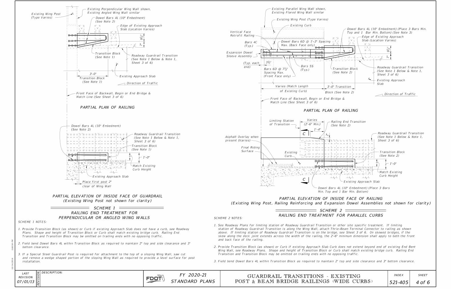
SCHEME 2
RAILING END TREATMENT FOR PARALLEL CURBS
PARTIAL ELEVATION OF INSIDE FACE OF RAILING
(Existing Wing Post, Railing Reinforcing and Expansion Dowel Assemblies not shown for clarity)
PARTIAL PLAN OF RAILING
PARTIAL ELEVATION OF INSIDE FACE OF GUARDRAIL
(Existing Wing Post not shown for clarity)
SCHEME 1
RAILING END TREATMENT FOR
PERPENDICULAR OR ANGLED WING WALLS
SCHEME 1 NOTES:
1. Provide Transition Block (as shown) or Curb if existing Approach Slab does not have a curb, see Roadway
Plans. Shape and height of Transition Block or Curb shall match existing bridge curb. Railing End
Transition and Transition Block may be omitted on trailing ends with no opposing traffic.
2. Field bend Dowel Bars 4L within Transition Block as required to maintain 2" top and side clearance and 3"
bottom clearance.
3. If a Special Steel Guardrail Post is required for attachment to the top of a sloping Wing Wall, saw cut
and remove a wedge shaped portion of the sloping Wing Wall as required to provide a level surface for post
installation.
Front Face of Backwall, Begin or End Bridge &
Match Line (See Sheet 3 of 6)Front Face of Backwall, Begin or End Bridge &
Match Line (See Sheet 3 of 6)
Roadway Guardrail Transition
(See Note 1 Below & Note 1,
Sheet 3 of 6)
Roadway Guardrail Transition
(See Note 1 Below & Note 1,
Sheet 3 of 6)
C
C
Dowel Bars 4L (10" Embedment) (Place 3 Bars Min.
Top and 1 Bar Min. Bottom) (See Note 3)
Roadway Guardrail Transition
(See Note 1 Below & Note 1,
Sheet 3 of 6)
Roadway Guardrail Transition
(See Note 1 Below & Note 1,
Sheet 3 of 6)
PARTIAL PLAN OF RAILING
SCHEME 2 NOTES:
1. See Roadway Plans for limiting station of Roadway Guardrail Transition or other site specific treatment. If limiting
station of Roadway Guardrail Transition is along the Wing Wall, attach Thrie-Beam Terminal Connector to railing as shown
above. If limiting station of Roadway Guardrail Transition is on the bridge, see Sheet 3 of 6. On skewed bridges, if the
skew along the deck joint extends across the width of the railing, the 2'-6" minimum dimension shall apply to both the front
and back face of the railing.
2. Provide Transition Block (as shown) or Curb if existing Approach Slab Curb does not extend beyond end of existing End Bent
Wing Wall, see Roadway Plans. Shape and height of Transition Block or Curb shall match existing bridge curb. Railing End
Transition and Transition Block may be omitted on trailing ends with no opposing traffic.
3. Field bend Dowel Bars 4L within Transition Block as required to maintain 2" top and side clearance and 3" bottom clearance.
10/14/2019
3:0
8:5
9 P
M
RE
VISIO
N DESCRIPTION:
REVISION
LAST
ofSTANDARD PLANS
FY 2020-21 SHEETINDEX GUARDRAIL TRANSITIONS - EXISTING
POST & BEAM BRIDGE RAILINGS (WIDE CURBS)
07/01/13 4 6 521-405

Existing Approach Slab
2'-
0"
Min.
Match Existing
Curb Height on
Bridge
Begin Flared Portion
of Vertical Face
Retrofit Railing
Final Riding
Surface
Asphalt Overlay when
present (Varies)
Limiting Station
of Transition
Varies (1'-0" Min.)
Parallel Portion of Vertical Face Retrofit
Railing if present (See Note 1)
Varies (Match Length of Existing Flared Curb)
Direction of Traffic
Existing Approach
Slab
end)
(Typ. each 312"
Bars 5S (Field
Bend) (Typ.)
Bars 6D @ 712"
Spacing Max.
(Front Face only)
Dowel Bars 4N
@ 1'-3" (Typ.)
Edge of Existing Approach
Slab (Location Varies)
Bars 4A @ 9" Max. (Field Bend
as required to maintain
clearance) (Typ.)
Existing Flared Wing WallExisting Wing Post (Type Varies)Parallel portion of Existing
Curb and Wing Wall may or
may not exist (length varies)
Dowel Bars 6D @ 1'-3" Spacing
Max. (Back Face only)Vertical Face Retrofit Railing
Bars 4C (Typ.)
Expansion Dowel
Sleeve Assembly
Bars 6D cut to clear Backwall
Gutter Line (Cut Exist.
Approach Slab along
this line)
Parallel portion of Existing Curb
and Wing Wall may or may not
exist (length varies)Vertical Face
Retrofit Railing
Existing Wing Post
(Type Varies)
Existing Flared Wing Wall
Existing Curb
Edge of Existing Approach
Slab (Location Varies)
Existing Approach Slab
Direction of Traffic
Varies (Match Length of Existing Flared Curb)
Bars 6D @ 712" Spacing
Max. (Front Face only)
312"(Typ. each
end)
Expansion
Dowel
Sleeve
Assembly
Bars 4C
(Typ.)
Dowel Bars 6D @ 1'-3" Spacing
Max. (Back Face only)
Bars 5S (Field
Bend) (Typ.)
Parallel Portion of Vertical Face Retrofit
Railing if present (See Note 1)
Varies (1'-0" Min.)
Limiting Station
of Transition
Begin Flared Portion of Vertical
Face Retrofit Railing
Existing Curb
Asphalt Overlay
when present
(Varies)Final Riding
Surface
Existing Approach Slab
PARTIAL PLAN OF RAILING
PARTIAL ELEVATION OF INSIDE FACE OF RAILING
(Existing Wing Post, Railing Reinforcing and Expansion Dowel Assemblies not shown for clarity)
SCHEME 4
RAILING END TREATMENT FOR FLARED CURBS
PARTIAL ELEVATION OF INSIDE FACE OF RAILING
(Existing Wing Post, Railing Reinforcing and Expansion Dowel Assemblies not shown for clarity)
SCHEME 3
RAILING END TREATMENT FOR FLARED CURBS
C-I-P Curb
Front Face of Backwall, Begin or End Bridge &
Match Line (See Sheet 3 of 6)
SCHEME 4 NOTES:
1. See Roadway Plans for limiting station of Roadway Guardrail Transition or other site specific treatment. If limiting station
of Roadway Guardrail Transition is along the Wing Wall, attach Thrie-Beam Terminal Connector to railing as shown above.
If limiting station of Roadway Guardrail Transition is on the bridge, see Sheet 3 of 6.
2. Dowel Bars 4N may be installed on a maximum angle of 45° to the cut edge of the Approach Slab as shown to facilitate
drilling of holes and installation of bars.
3. At the Contractor's option, along the length of the Approach Slab curb that is to be replaced, Dowel Bars 6D may be cast
in with the new section of curb as shown or they may be installed in drilled holes in the new section of curb using an
Adhesive Bonding Material System with a 1'-0" minimum embedment.
Front Face of Backwall, Begin or End
Bridge & Match Line (See Sheet 3 of 6)
D
D
C
C
Roadway Guardrail Transition
(See Note 1 Below & Note 1,
Sheet 3 of 6)Roadway Guardrail Transition
(See Note 1 Below & Note 1,
Sheet 3 of 6)
PARTIAL PLAN OF RAILING
Roadway Guardrail Transition
(See Note 1 Below & Note 1,
Sheet 3 of 6)Roadway Guardrail Transition
(See Note 1 Below & Note 1,
Sheet 3 of 6)
SCHEME 3 NOTE:
1. See Roadway Plans for limiting station of Roadway Guardrail Transition or other site specific
treatment. If limiting station of Roadway Guardrail Transition is along the Wing Wall, attach
Thrie-Beam Terminal Connector to railing as shown above. If limiting station of Roadway
Guardrail Transition is on the bridge, see Sheet 3 of 6.
Organic Felt
Bond Breaker
10/14/2019
3:0
9:0
0 P
M
RE
VISIO
N DESCRIPTION:
REVISION
LAST
ofSTANDARD PLANS
FY 2020-21 SHEETINDEX GUARDRAIL TRANSITIONS - EXISTING
POST & BEAM BRIDGE RAILINGS (WIDE CURBS)
11/01/16 5 6 521-405

Dowel Bars 4N @ 1'-3" (Typ.)
2" Min. Clear. Top
and Sides, 4" Min.
Clear. Bottom
2'-
0" (Min.)
Bars 4A @ 9" Max.
Existing Approach Slab
Asphalt Overlay
when present
(Varies)
Final Riding
Surface
2"
Min.
4"
Varie
s
Dowel Bars 6D
(See Note 5)
Bars 5S
(Typ.)
2" Clear
Existing Wing Post
(Type Varies)
10"
Varies
2'-
10"
(Typ.)
� Thrie-Beam
Guardrail Bolts
3ƀ"
3 sp.
@ 3
Ƃ"
= 11
Ɓ"
Varie
s (3
Ƃ"
Min.)
Parallel portion of Existing
Flared Wing Wall may or may
not exist (length varies)
Existing Wing Post (Type Varies)
Existing Flared Wing Wall shown,
Existing Parallel Wing Wall similar
Bars 4A @ 9" Max. (Field Bend as
required to maintain clearance) (Typ.)
Bars 4M (See
Note 4)Transition Block
(See Note 3)
Edge of Existing Approach
Slab (Location Varies)
7"
Existing Approach SlabBlock (See Note 3)
3'-0" Transition
Gutter Line (Cut
Exist. Approach
Slab along this line)
Dowel Bars 4N
@ 1'-3" (Typ.)
Varies (Match Length of Existing Curb)
Bars 5S
Dowel Bars 6D @ 1'-3" Spacing
Max. (Back Face only)
Vertical Face
Retrofit Railing
Bars 4C (Typ.)
Expansion Dowel
Sleeve Assembly
Bars 6D cut to
clear Backwall
(Typ. each
end)
Limiting Station
of Transition
Varies
(2'-6" Min.)Railing End Transition
(See Note 3)
Direction of Traffic
9ƀ"
Dowel Bars 6D @ 7ƀ" Spacing
Max. (Front Face only)
3ƀ"
1'-4"
2" Transition Block
(See Note 3)
Match Existing
Curb Height on
Bridge
1'-
0"
Min.
2'-
0"
Min.
Bars 4M (1'-0" Min.
Embedment, See Note 4)
Existing Approach Slab
Asphalt Overlay when
present (Varies)Final Riding
Surface
SCHEME 5
RAILING END TREATMENT FOR PARALLEL CURBS
PARTIAL PLAN OF RAILING
C-I-P Curb
*** Curb heights vary from 5" Min. to
10" Max. Match height and shape
of existing curb on bridge.
*** Curb
Varie
s
Front Face of Backwall, Begin or End
Bridge & Match Line (See Sheet 3 of 6)
PARTIAL ELEVATION OF INSIDE FACE OF RAILING
(Existing Wing Post, Railing Reinforcing and Expansion Dowel Assemblies not shown for clarity)
SCHEME 5 NOTES:
1. See Roadway Plans for limiting station of Roadway Guardrail Transition or other site specific treatment. If limiting station
of Roadway Guardrail Transition is along the Wing Wall, attach Thrie-Beam Terminal Connector to railing as shown above. If
limiting station of Roadway Guardrail Transition is on the bridge, see Sheet 3 of 6.
2. Dowel Bars 4N may be installed on a maximum angle of 45° to the cut edge of the Approach Slab as shown to facilitate
drilling of holes and installation of bars.
3. Provide Transition Block (as shown) or Curb if existing Approach Slab Curb does not extend beyond end of existing End Bent
Wing Wall, see Roadway Plans. Shape and height of Transition Block or Curb shall match existing bridge curb. Railing End
Transition and Transition Block may be omitted on trailing ends with no opposing traffic.
4. Field bend Dowel Bars 4M within Transition Block as required to maintain 2" top and side clearance and 3" bottom clearance.
5. At the Contractor's option, along the length of the Approach Slab curb that is to be replaced, Dowel Bars 6D may be cast in
with the new section of curb as shown or they may be installed in drilled holes in the new section of curb using an
Adhesive Bonding Material System with a 1'-0" minimum embedment.
Gutter Line (Cut
Existing Approach
Slab along this line)
Varies (1'-2" Min.)
Varies
(Type Varies)
Existing Wing Post
Wing Wall
Existing
Portion of Existing Approach
Slab with Integral Curb less
than 6" thick or portion of
Existing Approach Slab and
Curb with Floating Detached
Sidewalk to be removed
shown hatched.
Asphalt Overlay
when present
(Varies)
Bars 4A @ 9" Max., Min. 3 full length bars
required Top & Bottom (Field Bend to clear) (Typ.)
10" Min.
Embedment
Existing Approach Slab
Roadway Guardrail
Transition (See Note 1
Below & Note 1,
Sheet 3 of 6)
Roadway Guardrail
Transition (See Note 1
Below & Note 1,
Sheet 3 of 6)
D
D
SECTION D-D
TYPICAL SECTION THRU RAILING ALONG APPROACH SLAB
(SCHEME 4 SHOWN, SCHEME 5 SIMILAR)
Varies
3" (Max.) Preferred
1" Min.
Varies (1'-2" Min.)
TYPICAL SECTION THRU EXISTING APPROACH
SLAB AND END BENT WING WALL SHOWING LIMITS OF REMOVAL
(SCHEMES 4 AND 5 ONLY)
Organic Felt
Bond Breaker
Organic Felt Bond Breaker10/14/2019
3:0
9:0
1 P
M
RE
VISIO
N DESCRIPTION:
REVISION
LAST
ofSTANDARD PLANS
FY 2020-21 SHEETINDEX GUARDRAIL TRANSITIONS - EXISTING
POST & BEAM BRIDGE RAILINGS (WIDE CURBS)
11/01/16 6 6 521-405