GENERAL MANUAL CONTENTS - BWS Manufacturing · Hoist & H-Frame Diagram 25 ... Tools to Service Your...
58
2 ALL SEASON SANDER GENERAL MANUAL CONTENTS INTRODUCTION 4 Products 4 BWS COMPANY HISTORY 5 Quality Policy 6 COMPLIANCE PLATE 7 WARNING 8 MAINTENANCE & OPERATION 9 Operation 9 Control of Spreader 9 Inner Floor 10 Maintenance Instructions 10 Gear Box 11 Bleeding Procedure 11 Grease Fittings 12 QUALITY CONTROL 13 Pre-operating maintenance 13 INSTALLATION PROCEDURE 14 Installation of Cylinder Base 14 Installation of Hinges System 15 Air Operated Tailgate System 15 Installation of BWS Mud flap 16 PARTS LISTINGS 17 All-Season Sander Box Main Assembly (22201799) 17 All-Season Sander Box Main Parts List (22201799) 18 Conveyor Assembly (22201833) 19 Conveyor Parts List (22201833) 20 Hydraulic Cylinder Base & Body Prop for 21 All Season Dump/Sander diagram (40959280) 21 Hydraulic Cylinder Base & Body Prop for All Season Dump/Sander Parts List 22 Fluid Control Diagram 23 Fluid Control Parts List 24 Hoist & H-Frame Diagram 25 Hoist & H-Frame Parts List 26 Truck Frame Cut Line 27 Spinner Location and elevation 28 13’ F-model all season Sander/Dump body 29 All Season Sander/Dump Hydraulic Components 29 SAFETY FEATURES 30 Inner Floor Prop 30 Sander Box Prop 30 SUPPLIERS 31 Mailhot Cylinder 31 Introduction 32 Internal Configuration 33 Identifying the Correct Cylinder for Your Needs 35 Safety First 36 Warnings 38 Installation of the Cylinder 39 Tools to Service Your Telescopic Cylinder 41 Disassembly, Assembly, Test & Bleeding Procedure 43 Trouble Shooting 49 Warranty 50
Transcript of GENERAL MANUAL CONTENTS - BWS Manufacturing · Hoist & H-Frame Diagram 25 ... Tools to Service Your...

2ALL SEASON SANDER
GENERAL MANUAL CONTENTSINTRODUCTION 4
Products 4BWS COMPANY HISTORY 5
Quality Policy 6COMPLIANCE PLATE 7WARNING 8MAINTENANCE & OPERATION 9
Operation 9Control of Spreader 9Inner Floor 10Maintenance Instructions 10Gear Box 11Bleeding Procedure 11Grease Fittings 12
QUALITY CONTROL 13Pre-operating maintenance 13
INSTALLATION PROCEDURE 14Installation of Cylinder Base 14Installation of Hinges System 15Air Operated Tailgate System 15Installation of BWS Mud flap 16
PARTS LISTINGS 17All-Season Sander Box Main Assembly (22201799) 17All-Season Sander Box Main Parts List (22201799) 18Conveyor Assembly (22201833) 19Conveyor Parts List (22201833) 20Hydraulic Cylinder Base & Body Prop for 21All Season Dump/Sander diagram (40959280) 21Hydraulic Cylinder Base & Body Prop for All Season Dump/Sander Parts List 22Fluid Control Diagram 23Fluid Control Parts List 24Hoist & H-Frame Diagram 25Hoist & H-Frame Parts List 26Truck Frame Cut Line 27Spinner Location and elevation 2813’ F-model all season Sander/Dump body 29All Season Sander/Dump Hydraulic Components 29
SAFETY FEATURES 30Inner Floor Prop 30Sander Box Prop 30
SUPPLIERS 31Mailhot Cylinder 31
Introduction 32Internal Configuration 33Identifying the Correct Cylinder for Your Needs 35Safety First 36Warnings 38Installation of the Cylinder 39Tools to Service Your Telescopic Cylinder 41Disassembly, Assembly, Test & Bleeding Procedure 43Trouble Shooting 49Warranty 50

3ALL SEASON SANDER
SCHEMATICS 52Electrical Schematic 52Air Schematic 53Hydraulic Schematic 54
TROUBLE SHOOTING 55WARRANTY 56
BWS All Season Sander Warranty Agreement 561 Year Basic Warranty 56Paint/Finish 56Exclusions from BWS Warranty Coverage 57BWS Warranty Disclaimer and Limitations of Liability 57Warranty registration form 58
BWS Contact Information 59

4ALL SEASON SANDER
INTRODUCTIONThe BWS product you have just taken delivery of has been carefully designed and built for easy, low maintenance, reliable operation that meets the requirements of a shrewd transportation industry.
We take this opportunity to thank you for choosing BWS, and assure you of our interest in the continued safe and reliable operation of this equipment through its’ dealer and service network abroad. BWS requires that you and anyone else who will be operating or maintaining the unit, read this manual carefully and understand the safety, operation, maintenance and trouble shooting information contained in the operator’s manual.
FORESTRYLogging trailers, straight and drop framesHydraulic & air detachable goosenecksB-Train loggersJeepsTag-a-longs
GENERAL FREIGHTEquipment trailersHydraulic & Air Detachable GoosenecksHighway Drop DecksHighway FlatbedsB-Train FlatbedsPony Trailer
CONSTRUCTIONLow bed equipment trailersDetachable & fixed goosenecksHydraulic & air detachable goosenecksTag-a-long trailers, tilting & non-tilting decksDump trailersJeepsBoosters
HYDRO/TELEPHONECable Reel trailers
SPECIAL ORDER TRAILERSNuclear WasteGenerator TrailersWagon Type TrailersMilitary TrailersSpecialty Trailers for offshore productsA/S Dump SandersA/S U-Body Dump Sanders
OIL & GASOil field trailersEquipment trailersOil field jeeps / Oil field hydraulicsHydraulic goosenecksScissornecksTag-a-longs
PAVING & RECOVERYAggregate ScreenersHydraulic & air detachable goosenecksEquipment trailersTag-a-longsDump Trailer
SNOW & ICESander BodiesHopper SandersU BodyTurn Key Trucks
PRODUCTS

5ALL SEASON SANDER
BWS COMPANY HISTORYBWS products are engineered, designed and manufactured by BWS, located in Centreville, New Brunswick. It is a family owned and managed business that is dedicated and committed to delivering outstanding value. Its success is built on thinking like the customer and producing trailers that can be relied on year after year without fail.
Since 1967, it has gained and maintained the trust and respect of experienced customers who work in the oil fields, construction, snow & ice, equipment and machinery moving, forestry, road building, paving and private contracting industries.
Originally BWS manufactured custom trailers with a focus on forestry and agriculture. Having built a solid reputation in this rough off-road industry and operating in the tough Canadian environment, BWS continues today to manufacture trailers that are designed to meet the customers’ expectations in the environments in which they operate. The units are designed to go to work and stay at work.
BWS has expanded its product line into areas where it can continue to provide high quality solutions that deliver value.
The employees of BWS are a dedicated workforce with a “craftsman” mentality. Many of its senior people have past experience operating trailers and equipment and this has resulted in their philosophy of putting themselves in the shoes of their customers. BWS relies heavily on feedback from both their dealers and their customers. They build what performs, not just what sells and that is what has contributed to their significant growth throughout North America over the last several years.
6ALL SEASON SANDER
BWS Manufacturing is totally committed to understanding and meeting the quality needs and expectations of all our customers. Our company has a proud reputation for delivering quality equipment and components.
BWS strives for continuous improvement of our product and meeting the objectives of the company. We are also committed to the continuous improvement of our quality management system to insure its suitability to meet all company, customer, regulatory, legal and ISO requirements.
The entire BWS team will adhere to the spirit and intent of our quality policy, as well as the directives of this quality assurance manual and its supporting quality system documentation. We will continue to aggressively strive to insure that customer satisfaction is achieved at all times, and in all things.
QUALITY POLICY
QA-DOC-004-VER-001

7ALL SEASON SANDER
COMPLIANCE PLATEThe compliance plate is located on the road side of the trailer frame. The National Safety Mark (NSM) verifies compliance with all applicable Canadian Motor Vehicle Safety Standards (CMVSS) and/or American Federal Motor Vehicle Safety Standards (FMVSS) , and records the following information.
V.I.N. Vehicle Identification Number
DATE Date of Manufacture
TYPE (TRA/REM) in Canada onlyMODEL BWS ModelG.V.W.R Gross Vehicle Weight Rating is the sum of the trailer weight and the allowable trailer load.
G.A.W.R Gross Axle Weight Rating is the lowest capacity of all the individual components in the axle assembly. It reflects the “weakest link” in the entire suspension system, whether it be springs, axles, wheels, rims or tires.
RIM Rim Diameter x WidthTIRE Outside Diameter/Width R Inside Diameter
PRESSURE COLD Cold tire inflation pressure in psi (US) / kPa and psi (Can.) It is the practice of BWS to use maximum pressure for tire inflation.
NSM BWS has been assigned a registration number and has been authorized to use the NSM on
their products. The NSM signifies conformance with the CMVSS set by transport Canada.
TAG COMPLIANCE PLATE

8ALL SEASON SANDER
WARNINGAll air must be removed from the two inner floor side tipping cylinders prior to operation of the hydraulic system. Air must also be bled from the hydraulic system any time the hydraulic fluid gets low or if hoses have been removed for any reason. Failure to bleed the air may result in structural damage to the front headboard of the All Season Dump body.
Functional requirements for proper operation of your BWS All Season Sander include:• 23 gallons per minute of uninterrupted hydraulic fluid to the sander control valve.• A minimum of 8 gallons per minute to the spinner motor and 15 gallons per minute to the auger
motor.• High volume control valve for the cylinder.
Failure to provide any of the above will result in malfunction and may preclude compatibility with some electronic spreading devices.

9ALL SEASON SANDER
MAINTENANCE & OPERATIONOPERATION
CONTROL OF SPREADER
The BWS All Season Dump/Sander has been designed with the user in mind. To provide a unit that can be utilized 12 months of the year as a dump truck or as a mineral spreader.
To convert the unit from a dump truck to a spreader, lift and lock conveyor cover and open the conveyor discharge gate (approximately 2”).
All controls are in the truck cab. Select required knob positions to provide the desired spread pattern. Make sure discharge gate is properly adjusted to provide full opening when spreading sand and partly opened when spreading salt.
Hydra-Tac Hydraulics or Compuspread of Dickey-John:Refer to separate manual enclosed if applicable.
10ALL SEASON SANDER
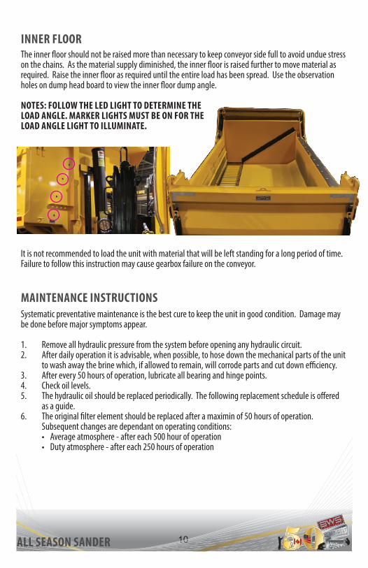
INNER FLOORThe inner floor should not be raised more than necessary to keep conveyor side full to avoid undue stress on the chains. As the material supply diminished, the inner floor is raised further to move material as required. Raise the inner floor as required until the entire load has been spread. Use the observation holes on dump head board to view the inner floor dump angle.
NOTES: FOLLOW THE LED LIGHT TO DETERMINE THE LOAD ANGLE. MARKER LIGHTS MUST BE ON FOR THE LOAD ANGLE LIGHT TO ILLUMINATE.
MAINTENANCE INSTRUCTIONSSystematic preventative maintenance is the best cure to keep the unit in good condition. Damage may be done before major symptoms appear.
1. Remove all hydraulic pressure from the system before opening any hydraulic circuit.2. After daily operation it is advisable, when possible, to hose down the mechanical parts of the unit
to wash away the brine which, if allowed to remain, will corrode parts and cut down efficiency.3. After every 50 hours of operation, lubricate all bearing and hinge points.4. Check oil levels. 5. The hydraulic oil should be replaced periodically. The following replacement schedule is offered
as a guide.6. The original filter element should be replaced after a maximin of 50 hours of operation.
Subsequent changes are dependant on operating conditions:• Average atmosphere - after each 500 hour of operation• Duty atmosphere - after each 250 hours of operation
It is not recommended to load the unit with material that will be left standing for a long period of time. Failure to follow this instruction may cause gearbox failure on the conveyor.

11ALL SEASON SANDER
GEAR BOXComplete Gear Box P/N 08305
1. Use an hex key/Allen wrench to reveal the input area at the top of the gear box.
2. Continue adding oil until it starts to seep out the bottom output.
3. Wipe the outside with a rag.4. Replace the plug.
BLEEDING PROCEDURE1. Ensure the inner floor is in the closed position.2. Loosen the bleeder screws located at the top and bottom of both inner
floor cylinders.3. Start the vehicle and engage the hydraulic pump.4. Have an operator gently open the inner floor cylinder valve to the raised
position.5. Once all of the air bubbles have been expelled and a constant flow of clear
oil is present, tighten bleeder screws and disengage the pump.6. Ensure that the hydraulic lines remain full of oil to prevent more air from
being trapped within the hydraulic system.7. Top up the hydraulic reservoir to full level.8. Check the hydraulic tank gauge. Make certain to read the gauge when all
cylinders are in the return position.9. Operate the inner floor up and down a few times to check for any leaks.
NOTE: FAILURE TO FOLLOW THESE PROCEDURES MAY RESULT IN FAILURE OF THE INNER FLOOR EQUALIZING SYSTEM AND THUS SERIOUS STRUCTURAL DAMAGE TO YOUR BWS ALL SEASON DUMP SANDER.

12AS132S-PROMOJT. UNDERHILLREV. 02016/06/07
BWS
Man
ufac
turin
g Lt
d.29
Haw
kins
Roa
dC
entre
ville
New
Bru
nsw
ick
Can
ada
E7K
1A4
AP
PR
OV
AL
DA
TE
: ___
____
____
____
SIG
NA
TU
RE
: ___
____
_W
O #
____
____
____
____
_
MO
DEL
: 231
3NB
13 F
T. N
B AL
L SE
ASO
N B
OD
YN
OTE
: ALL
DIM
ENSI
ON
S AR
E LO
ADED
& N
OM
INAL
.
DU
MPE
D E
LEVA
TIO
N
16" N
OM
. H.B
.69"
176"
OAL
90"54"
REA
R V
IEW
FRO
NT
VIEW
156"
I/S
137"
ELEV
ATIO
N
PLAN
96" O/S
48" TAILGATE
36" SIDES
49.8°
86"
80"
GREASE FITTINGS
10 FI
TTIN
GS
UNDE
R TH
E CO
NVEY
OR

13ALL SEASON SANDER
QUALITY CONTROLThe following check list is to be used on all season dump sanders BEFORE being used. BWS will not be responsible for damage resulting in negligence of this checklist. All BWS equipment is tested before leaving the factory.
PRE-OPERATING MAINTENANCE1. Check all bearings and apply the standard chassis lube of your choice if required, including all
sealed bearings in conveyor system as well as all grease fitting on the spinner assembly.
2. Check the oil level on the conveyor system gear reducer. This can be done by removing small plug. If the oil level is up to the inspection hole, it is acceptable. If not, fill with the proper fluid (#90 gear lube).
3. Check (with truck engine shut off) set screws in crank drive shaft to ensure that the unit is intact and operational.
4. Check all adjustments on conveyor and spinner assemblies to ensure the locking devices are tight.
5. Check hydraulic oil levels by observing the sight gauge. Oil level should full on the sight gauge. If not, bring up to half level using hydraulic oil #32.
NOTE: DO NOT OVER FILL THIS UNIT.
DAILY OPERATIONAL MAINTENANCEAfter every 50 hours of operation, step 1 should be repeated. After every 100 hours of operation, steps through 3 should be repeated.
SEASONAL MAINTENANCEAt the end of each season, you BWS unit should be washed or steamed thoroughly to ensure maximum life of the entire unit. Salt corrodes, not only the chassis, but the drive chain, bearing seals and gear box seals. Once the unit has been thoroughly cleaned, inspect complete unit for excessive wear of parts. Replacement parts are available through the BWS Parts Department in Centreville, NB.

14ALL SEASON SANDER
INSTALLATION PROCEDUREYour safety and that of others are the first considerations when engaging in the installation and maintenance of equipment. Always be conscious of weight. Never attempt to move heavy parts without the aid of a mechanical device. Do not allow heavy objects to rest in an unstable position. When raising a portion of the equipment, ensure that the adequate support is provided.
These warnings are given to alert the installer to the possibility of personal injuries and/or equipment damage resulting from improper installation and handling. Furthermore, the authorized dealer and the final stage installer have the full responsibility to certify that the completed all season sander vehicle conforms to all required safety rules or standards applicable in its area of operation.
BWS Manufacturing Ltd. will not be liable for any claim for loss of usage, any kind of injuries or any other claims that could be the product of a faulty on incomplete installation by an authorized dealer or distributor.
INSTALLATION OF CYLINDER BASELocate the pre-assembled BWS cylinder base at the appropriate position on the truck frame in regards to the position of the front body cross members.
1. Before any welding is started on the vehicle, make certain that the battery is disconnected to avoid any computer issues.
2. Install the mounting angles (2) under the pre-assembled BWS cylinder base.3. Match the drill holes on the truck frame in the proper location.4. Install the bolts (3) and proceed to the tightening procedure with the nuts (4).5. Proceed to the last adjustments between the mounting angles (2) and the cylinder base cross
members (6).6. Proceed with all welds needed to join the mounting angles (2) with the cylinder base cross
members (6).
Be sure the positioning guides (1) are correctly located on the cylinder base before proceeding with the welding. Allow a maximum pacing of 1/16” between the positioning guides welded on the dump body.

15ALL SEASON SANDER
INSTALLATION OF HINGES SYSTEM1. Establish the exact location of the hinge assembly (4) to be installed at the back extremity of the
truck frame (1).2. Trim the truck (1) to the required dimensions, then proceed with the hinge assembly (4)
installation.3. Install and fix the booster guard (2) and the horizontal bar (3).4. Install and weld the standard tow plate (5) as well as the heavy duty tow plate, if required.
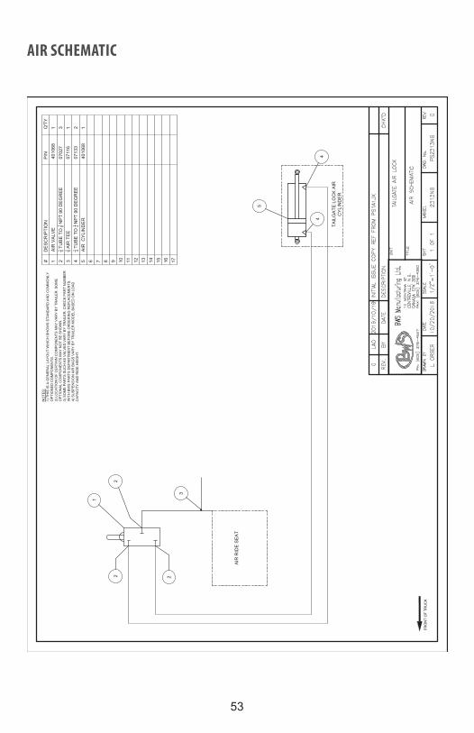
For safety, insure that the tailgate locking system is positively locked, only being opened by operating the pneumatic control, located in the cab of the truck, for dumping purposes.
See air schematic for further details.An indicator light helps the operator to know when the tailgate is open by illuminating on the cab controls.
NOTE: IN THE CASE OF A SYSTEM FAILURE, THE OPERATOR IS ABLE TO OPEN AND CLOSE THE TAILGATE MANUALLY. A TOOL STORED AT THE FRONT OF THE BOX, ON THE DRIVER SIDE TO ALLOW THE OPERATOR TO COMPLETE THE TASK.
AIR OPERATED TAILGATE SYSTEM

16ALL SEASON SANDER
INSTALLATION OF BWS MUD FLAPInstallation with loose mud flap brackets:1. Attach mud flap to the mount using back plate, nuts and washers.2. Make sure all nuts have been tightened.
NOTE: FRONT MUD FLAPS MAY BE INSTALLED IN FRONT OF THE FRONT AXLE OF SINGLE OR DOUBLE TRUCKS. REAR MUD FLAPS MUST BE INSTALLED AT THE BACK OF THE SINGLE OR DOUBLE AXLE TRUCKS, EITHER ON THE DUMP BODY OR THE TRUCK FRAME.

17
PARTS LISTINGSALL-SEASON SANDER BOX MAIN ASSEMBLY (22201799)

18ALL SEASON SANDER
ALL-SEASON SANDER BOX MAIN PARTS LIST (22201799)

19
TOP
VIEW
SCAL
E 1/
16
SID
E EL
EVAT
ION
VIE
WSC
ALE
1/16
ISO
VIE
WSC
ALE
1/25
SEC
TIO
N A
-ASC
ALE
1/16
SEC
TIO
N B
-BSC
ALE
1/16
Parts
Lis
tC
OM
MEN
TSAR
EA (S
Q.F
T.)
WID
THLE
NG
THD
ESC
RIP
TIO
NPA
RT
No.
STO
CK
No.
QTY
ITEM
ASSY
G
EAR
BO
X AD
JUST
ER A
SSEM
BLY
2220
1842
1
1ST
D
CO
MPL
ETE
MAI
N C
HAI
N A
LL S
EASO
N22
2018
34
12
STD
, ASS
'Y
GEA
RBO
X R
OD
WIT
H N
UTS
2220
1191
1
3ST
D, A
SS'Y
G
EAR
BOX
RO
D W
ITH
NU
TS22
2003
35
14
STD
, DW
G, I
RO
NW
7 in
FLAT
BAR
1/4
X 2
MS
2220
1800
5314
21
5ST
D, M
S, S
AW
2
1/2
in3/
8 C
F SQ
UAR
E BA
R22
2017
7052
381
6ST
D, M
S, S
AW
2
1/4
in1/
2" C
F SQ
UAR
E BA
R22
2017
6952
124
7ST
D, S
AW, M
AC
H.
33 1
/4 in
1 3/
4 D
IA. S
TRES
SPR
OO
F SH
AFT
2220
0408
4813
41
8ST
D, S
AW, M
AC
H.
27 in
1 3/
4 D
IA. S
TRES
SPR
OO
F SH
AFT
2220
0113
4813
41
9ST
OC
K
GEA
R B
OX,
DU
RST
50:
1, A
1126
-800
508
305
1
10ST
OC
K
MO
TOR
, HYD
GEA
R B
OX
( EAT
ON
101
-101
1-00
9).
0960
5
111
STO
CK
1
3/4
DIA
. 4-B
OLT
FLA
NG
E BE
ARIN
G02
018
2
12ST
OC
K
2202
9 SP
RO
CKE
T AL
667X
H B
9T
X 1
-3/4
C/W
SC
REW
S40
9522
0822
029
413
AA
BB
UN
IT
TITL
E
DR
AWN
BY
DA
TESC
ALE
SHT
MO
DE
LD
WG
. No.
RE
V
BWS
Man
ufac
turin
g Lt
d.10
MO
NTA
NA
ST.
C
ENTR
EV
ILLE
, N.B
. C
ANA
DA,
E7K
3E9
PH
: (50
6) 2
76-4
567
FAX:
(506
) 276
-438
0
MIL
LIN
G ±
.005
LATH
E ±
.005
DR
ILL
± .0
05SH
EAR
± 1
/16
PRO
CED
UR
ES: A
S PE
R A
PPR
OV
ED C
WB
PR
OC
ED
UR
ES O
NLY
SIZE
S, U
NO
: 100
% t
FOR
TH
INN
ER
ME
MBE
R T
HIC
KN
ESS
t <=
1/4
"75
% t
FOR
TH
INN
ER
ME
MB
ER T
HIC
KNES
S t >
1/4
"
SAW
± 1
/16
TOLE
RA
NC
ES:
WE
LDIN
G:
IRO
NW
OR
KER
± 1
/16
BRAK
E ±
1°
DA
TEBY
REV.
DESC
RIPT
ION
CHK'D
MAC
H. S
HO
P:U
NIT
STR
:
CO
NVE
YOR
PU
RC
HAS
ED P
ARTS
AS
SEM
BLY
PAR
T D
ETAI
L
LAO
7/14
/201
6AS
NO
TED
1 o
f 2
2313
2220
1833
1
-
-
1LA
O7/
14/2
016
INIT
IAL
ISSU
E.
MAI
N A
SSEM
BLY
7
12
12
9
48
2
150
5/8
7 3/8
150
5/8
13
13
13
8
1110
1
5
2
24 1/2
18
1 5/16
7 1/
16
4
CONVEYOR ASSEMBLY (22201833)

20ALL SEASON SANDER
TOP VIEWSCALE 1/16
SIDE ELEVATION VIEWSCALE 1/16
ISO VIEWSCALE 1/25
SECTION A-ASCALE 1/16
SECTION B-BSCALE 1/16
Parts ListCOMMENTSAREA (SQ.FT.)WIDTHLENGTHDESCRIPTIONPART No.STOCK No.QTYITEM
ASSY GEAR BOX ADJUSTER ASSEMBLY22201842 11STD COMPLETE MAIN CHAIN ALL SEASON22201834 12STD, ASS'Y GEARBOX ROD WITH NUTS22201191 13STD, ASS'Y GEARBOX ROD WITH NUTS22200335 14STD, DWG, IRONW 7 inFLAT BAR 1/4 X 2 MS222018005314215STD, MS, SAW 2 1/2 in3/8 CF SQUARE BAR22201770523816STD, MS, SAW 2 1/4 in1/2" CF SQUARE BAR22201769521247STD, SAW, MACH. 33 1/4 in1 3/4 DIA. STRESSPROOF SHAFT222004084813418STD, SAW, MACH. 27 in1 3/4 DIA. STRESSPROOF SHAFT222001134813419STOCK GEAR BOX, DURST 50:1, A1126-800508305 110STOCK MOTOR, HYD GEAR BOX ( EATON 101-1011-009).09605 111STOCK 1 3/4 DIA. 4-BOLT FLANGE BEARING02018 212STOCK 22029 SPROCKET AL667XH B 9T X 1-3/4 C/W SCREWS4095220822029413
A A
B B
UNIT
TITLE
DRAWN BY DATE SCALE SHT MODEL DWG. No. REV
BWS Manufacturing Ltd.10 MONTANA ST. CENTREVILLE, N.B. CANADA, E7K 3E9PH: (506) 276-4567FAX: (506) 276-4380
MILLING ± .005LATHE ± .005 DRILL ± .005SHEAR ± 1/16
PROCEDURES: AS PER APPROVED CWB PROCEDURES ONLYSIZES, UNO: 100% t FOR THINNER MEMBER THICKNESS t <= 1/4"75% t FOR THINNER MEMBER THICKNESS t > 1/4"
SAW ± 1/16TOLERANCES:
WELDING:
IRONWORKER ± 1/16 BRAKE ± 1°
DATEBYREV. DESCRIPTION CHK'D
MACH. SHOP:UNITS
TR:
CONVEYOR PURCHASED PARTS ASSEMBLY
PART DETAIL
LAO 7/14/2016 AS NOTED 1 of 2 2313 22201833 1
- -
1 LAO 7/14/2016 INITIAL ISSUE.
MAIN ASSEMBLY
7
12
12
9
4 82
150 5/8
7 3/
8
150 5/8
13
13
13
8
1110
1
5
2
24 1
/2
18
1 5/
16
7 1/16
4
CONVEYOR PARTS LIST (22201833)

21
FRO
NT
SCAL
E 1/
10
ELEV
ATIO
NSC
ALE
1/10
END
SCAL
E 1/
10
VIEW
9SC
ALE
1/10
Parts
Lis
tC
OM
MEN
TSAR
EA
(SQ
.FT.
)W
IDTH
LEN
GTH
DES
CR
IPTI
ON
PAR
T N
o.S
TOC
K N
o.Q
TYIT
EMD
WG
, IR
ON
W, B
RAK
E0.
194
in7
inFL
AT B
AR 3
/8 X
440
9573
3653
384
11
DW
G, S
AW, D
RIL
L
44
inH
SS 3
X 3
X 3
/840
9573
3554
3337
51
2D
WG
, SAW
, DR
ILL,
TAP
0.03
1 1/
2 in
3 1/
8 in
FLAT
BAR
1/4
X 1
-1/2
MS
2220
1482
5314
112
13
MS,
IRO
NW
0.46
5 in
13 1
/4 in
FLAT
BAR
3/8
" X 5
" MS
4095
9281
5338
51
4M
S,IR
ON
W
1 in
3 1/
2 in
FLAT
BAR
1/4
" X 1
" M
S40
9593
1253
141
15
MS,
IRO
NW
11 in
FLAT
BAR
3/8
" X 2
" MS
4095
9283
5338
22
6ST
D, L
ASER
7
in8
7/8
inPL
ATE
1/2
50W
2220
1542
7212
27
STO
CK
Bo
lt, H
ex 7
/8-9
UN
C -
5.5
0327
9
18
STO
CK
7/
8 St
d N
C N
yloc
k N
ut03
243
1
9ST
OC
K
Nut
, Hex
1/2
- 13
UN
C03
193
1
10ST
OC
K
Bolt,
Hex
1/2
-13
UN
C -
1.5
0310
6
111
STO
CK
H
-FR
AME
AC40
4009
586
0958
61
12ST
OC
K
PIN
Q/R
STA
INLE
SS #
233-
829
2245
523
3-82
91
13ST
OC
K, C
UT
C
HAI
N, 1
/8" (
14 L
INK
S)
0400
11
14
UN
IT
TITL
E
DR
AWN
BY
DA
TESC
ALE
SHT
MO
DE
LD
WG
. No.
RE
V
BWS
Man
ufac
turin
g Lt
d.10
MO
NTA
NA
ST.
C
ENTR
EV
ILLE
, N.B
. C
ANA
DA,
E7K
3E9
PH
: (50
6) 2
76-4
567
FAX:
(506
) 276
-438
0
MIL
LIN
G ±
.005
LATH
E ±
.005
DR
ILL
± .0
05SH
EAR
± 1
/16
PRO
CED
UR
ES: A
S PE
R A
PPR
OV
ED C
WB
PR
OC
ED
UR
ES O
NLY
SIZE
S, U
NO
: 100
% t
FOR
TH
INN
ER
ME
MBE
R T
HIC
KN
ESS
t <=
1/4
"75
% t
FOR
TH
INN
ER
ME
MB
ER T
HIC
KNES
S t >
1/4
"
SAW
± 1
/16
TOLE
RA
NC
ES:
WE
LDIN
G:
IRO
NW
OR
KER
± 1
/16
BRAK
E ±
1°
DA
TEBY
REV.
DESC
RIPT
ION
CHK'D
MAC
H. S
HO
P:U
NIT
STR
:
DU
MP
PRO
P A
SSEM
BLY
201
4
PAR
T D
ETAI
L
LAO
7/8/
2014
AS N
OTE
D1
of 1
AS
4095
9280
4
-
-
4LA
O2/
3/20
15AS
SEM
BLY
REV
ISE
D
3LA
O9/
15/2
014
ASS
EMBL
Y R
EVIS
ED
2
LAO
7/11
/201
4C
HAN
GED
222
0148
3 AN
D 4
0957
334
TO P
HAN
TOM
VIE
W
1LA
O4/
26/2
012
INIT
IAL
ISSU
E
MAI
N A
SSEM
BLY
0
7 9/16
05
7 5/
16
11 3
/8
50 3
/4
0
1/4
3 1/8
3 15/16
5 5/8
7 5/16
9 1/2
19 3/4
31
31 1/4
0
3 1/8
8 1/8
9 1/2
0
15/1
62
2 1/
16
7 9/
16
15 1
/8
1413
8
4
2
6
6
1 5/
16
1 15
/16
80°
1/8
3
0
7/16
4 9/16
5
3
2
11
10
79
6
HYDRAULIC CYLINDER BASE & BODY PROP FOR ALL SEASON DUMP/SANDER DIAGRAM (40959280)

22ALL SEASON SANDER
FRONTSCALE 1/10
ELEVATIONSCALE 1/10
ENDSCALE 1/10
VIEW9SCALE 1/10
Parts ListCOMMENTSAREA (SQ.FT.)WIDTHLENGTHDESCRIPTIONPART No.STOCK No.QTYITEM
DWG, IRONW, BRAKE0.194 in7 inFLAT BAR 3/8 X 4409573365338411DWG, SAW, DRILL 44 inHSS 3 X 3 X 3/840957335543337512DWG, SAW, DRILL,TAP0.031 1/2 in3 1/8 inFLAT BAR 1/4 X 1-1/2 MS22201482531411213MS, IRONW0.465 in13 1/4 inFLAT BAR 3/8" X 5" MS409592815338514MS,IRONW 1 in3 1/2 inFLAT BAR 1/4" X 1" MS409593125314115MS,IRONW 11 inFLAT BAR 3/8" X 2" MS409592835338226STD, LASER 7 in8 7/8 inPLATE 1/2 50W22201542721227STOCK Bolt, Hex 7/8-9 UNC - 5.503279 18STOCK 7/8 Std NC Nylock Nut03243 19STOCK Nut, Hex 1/2 - 13 UNC03193 110STOCK Bolt, Hex 1/2-13 UNC - 1.503106 111STOCK H-FRAME AC40400958609586112STOCK PIN Q/R STAINLESS #233-82922455233-829113STOCK, CUT CHAIN, 1/8" (14 LINKS) 04001114
UNIT
TITLE
DRAWN BY DATE SCALE SHT MODEL DWG. No. REV
BWS Manufacturing Ltd.10 MONTANA ST. CENTREVILLE, N.B. CANADA, E7K 3E9PH: (506) 276-4567FAX: (506) 276-4380
MILLING ± .005LATHE ± .005 DRILL ± .005SHEAR ± 1/16
PROCEDURES: AS PER APPROVED CWB PROCEDURES ONLYSIZES, UNO: 100% t FOR THINNER MEMBER THICKNESS t <= 1/4"75% t FOR THINNER MEMBER THICKNESS t > 1/4"
SAW ± 1/16TOLERANCES:
WELDING:
IRONWORKER ± 1/16 BRAKE ± 1°
DATEBYREV. DESCRIPTION CHK'D
MACH. SHOP:UNITS
TR:
DUMP PROP ASSEMBLY 2014
PART DETAIL
LAO 7/8/2014 AS NOTED 1 of 1 AS 40959280 4
- -
4 LAO 2/3/2015 ASSEMBLY REVISED 3 LAO 9/15/2014 ASSEMBLY REVISED 2 LAO 7/11/2014 CHANGED 22201483 AND 40957334 TO PHANTOM VIEW 1 LAO 4/26/2012 INITIAL ISSUE
MAIN ASSEMBLY
0
7 9/
16
0
5
7 5/16
11 3/8
50 3/4
0
1/4
3 1/
8
3 15
/16
5 5/
8
7 5/
16
9 1/
2
19 3
/4 31
31 1
/4
0 3 1/
8
8 1/
8
9 1/
2
0
15/16
2
2 1/16
7 9/16
15 1/8
1413
8
4
2
6
6
1 5/16
1 15/16
80°
1/8
3
0
7/16
4 9/
16 5
3
2
11
10
79
6
HYDRAULIC CYLINDER BASE & BODY PROP FOR ALL SEASON DUMP/SANDER PARTS LIST

23
FLUID CONTROL DIAGRAM
MACHINE SHOP: -
TR
:
-

24ALL SEASON SANDER
MA
CH
INE
SH
OP
:
-
TR: -
FLUID CONTROL PARTS LIST

25
HOIST & H-FRAME DIAGRAM
ISO VIEWSCALE 1/12
Parts ListCOMMENTSAREA (SQ.FT.)WIDTHLENGTHDESCRIPTIONPART No.STOCK No.QTYITEM
ASS'Y NBDOT MAILHOT CYLINDER 09705 ASSEMBLY22201891 11ASS'Y 14 FT U-BODY SAFETY PROP ASS'Y40959280 12
UNIT
TITLE
DRAWN BY DATE SCALE SHT MODEL DWG. No. REV
BWS Manufacturing Ltd.10 MONTANA ST. CENTREVILLE, N.B. CANADA, E7K 3E9PH: (506) 276-4567FAX: (506) 276-4380
MILLING ± .005LATHE ± .005 DRILL ± .005SHEAR ± 1/16
PROCEDURES: AS PER APPROVED CWB PROCEDURES ONLYSIZES, UNO: 100% t FOR THINNER MEMBER THICKNESS t <= 1/4"75% t FOR THINNER MEMBER THICKNESS t > 1/4"
SAW ± 1/16TOLERANCES:
WELDING:
IRONWORKER ± 1/16 BRAKE ± 1°
DATEBYREV. DESCRIPTION CHK'D
MACH. SHOP:UNITS
TR:
HOIST AND H-FRAME
ASSEMBLY DETAIL
LAO 10/31/2016 AS NOTED 1 of 1 2313NB 22201235 1
- -
1 LAO 10/31/2016 INITIAL ISSUE.

26ALL SEASON SANDER
ISO VIEWSCALE 1/12
Parts ListCOMMENTSAREA (SQ.FT.)WIDTHLENGTHDESCRIPTIONPART No.STOCK No.QTYITEM
ASS'Y NBDOT MAILHOT CYLINDER 09705 ASSEMBLY22201891 11ASS'Y 14 FT U-BODY SAFETY PROP ASS'Y40959280 12
UNIT
TITLE
DRAWN BY DATE SCALE SHT MODEL DWG. No. REV
BWS Manufacturing Ltd.10 MONTANA ST. CENTREVILLE, N.B. CANADA, E7K 3E9PH: (506) 276-4567FAX: (506) 276-4380
MILLING ± .005LATHE ± .005 DRILL ± .005SHEAR ± 1/16
PROCEDURES: AS PER APPROVED CWB PROCEDURES ONLYSIZES, UNO: 100% t FOR THINNER MEMBER THICKNESS t <= 1/4"75% t FOR THINNER MEMBER THICKNESS t > 1/4"
SAW ± 1/16TOLERANCES:
WELDING:
IRONWORKER ± 1/16 BRAKE ± 1°
DATEBYREV. DESCRIPTION CHK'D
MACH. SHOP:UNITS
TR:
HOIST AND H-FRAME
ASSEMBLY DETAIL
LAO 10/31/2016 AS NOTED 1 of 1 2313NB 22201235 1
- -
1 LAO 10/31/2016 INITIAL ISSUE.
HOIST & H-FRAME PARTS LIST

27
TRUCK FRAME CUT LINE

28
SPINNER LOCATION AND ELEVATION

29ALL SEASON SANDER
13’ F-MODEL ALL SEASON SANDER/DUMP BODY
QTY BWS PART # DESCRIPTION2 17258 lynch pin
3 04058 1/2” diameter clevis pin
3 04056 1/2” clevis
1 09705 telescopic cylinder CS 130-6-3
1 09283 hoist blocks and bolts
2 22200117 tailgate latch
1 11005 spreader gate jack
1 222200627 conveyor chain
1 02011 1 3/4” take-up bearing
1 40953264 discharge chute
1 19080 1/2” x 6” 80” rubber belting1 222001193 49” x 93” box style tailgate
4 22200626 bearing block c/w neoprene bushing
1 22201754 21” spreader gate door
2 19063 rod end
1 22201334 1 1/4” x 155” floor hinge pin
1 22201830 manual tailgate latch handle
1 22202022 inner floor safety prop
1 22201760 discharge end plate
ALL SEASON SANDER/DUMP HYDRAULIC COMPONENTS
QTY BWS PART # DESCRIPTION1 09604 1/4” hydraulic motor for spinner
1 09705 hoist cylinder M100-4.5 - 3

30ALL SEASON SANDER
SAFETY FEATURESINNER FLOOR PROP
SANDER BOX PROP
Used for maintenance when operator is working under the unit.
It is recommended that two people perform this operation.
1. Raise the inner floor to the full angle. 2. Remove pin from the prop and move to the
support position on the frame, inside the angle kick-out stop.
3. Lower the inner floor down until the weight is being supported by the prop.
Used for maintenance when operator is working under the unit.
1. Raise the sander box.2. Pull the pin on the prop and move it to the
desired position. 3. Lower the sander box until the prop is
holding the full weight.

31
SUPPLIERS
Mailhot Industries www.mailhotindustries.com
C-TypeSingle & Double Acting Telescopic Cylinder
Maintenance
MAILHOT CYLINDER

32
Mailhot Industries www.mailhotindustries.com C-Type Telescopic Cylinders 2Updated 2/4/2005
NOTICE
Before starting any work on the C-series single or Double Acting telescopic cylinder it is important toverify the warranty status of the product. Unauthorized service of a cylinder within the warranty period without the consent of Mailhot Industries Inc. may void the warranty. Please contact the customerservice department in your region to obtain an R.G.A. and further instructions.
St-Jacques, Quebec, Canada (450) 839-3663 or (800) 563-3663Guelph, Ontario, Canada (519) 763-6116 or (800) 668-6810Edmonton, Alberta, Canada (780) 482-2121 or (888) 988-2121Hudson, New Hampshire, USA (603) 880-9380 or (800) 624-5468Mailhot, Mexico (011) 5255-586-4583
DISCLAIMER
This maintenance manual is intended to provide general guidance when servicing your C-CSseries Single or Double Acting telescopic cylinder manufactured by Mailhot Industries Inc. All illustrations and photos should only be used as reference for disassembling and assembling the hydraulic cylinder. Mailhot Industries Inc. will not be liable and is not responsible fordamages due to inadequate tools, incorrect procedures, incorrect and/or aftermarketcomponents used and for any other damages. Please contact the Mailhot Industries Inc.customer service department in your region for further information.
INTRODUCTION
This manual was created to provide you with the necessary information to perform general disassembly and assembly of the C-series Single and Double Acting telescopic cylinder, manufactured by Mailhot Industries Inc.
Please be sure to closely follow the recommendations given. We believe this manual can be a useful tool for you and is intended to further enhance the quality of service provided by Mailhot Industries Inc.
GENERAL INFORMATIONBefore starting work on any hydraulic cylinder, be sure the work area is clean, and offers enough space to extend the cylinder to its full stroke. Work area obstructions or lack of space could make the cylinder difficult to handle increasing the risk for injury or potential damage to the cylinder.
©2003 "MAILHOT INDUSTRIES INC." All rights reserved.This document can not be reproduced in part or in whole without explicit permission from "Mailhot Industries Inc."
WARNINGIt is strongly recommended to take all necessary precautions to avoid an accident during the disassembly and
assembly process. During removal of the cylinder, it is recommended that the safety prop(s) and a secondary support be used to keep the truck body in the open position at all times.
INTRODUCTION

33
Mailhot Industries www.mailhotindustries.com C-Type Telescopic Cylinders 3Updated 2/4/2005
C-CS Series Single and Double Acting Telescopic Cylinder
Internal ConfigurationAll cylinders are the same! False! Our new generation of C-CS series telescopic cylinders has a uniquedesign that uses 40% less parts than comparable models. This simplified concept improves performance and makes assembly and disassembly a more manageable task. All gland nuts are removable using a minimal set of basic tools.
SAE OIL PORT
IMPROVED INTERNALLY THREADED GLANDS/WIPER, U-CUP, O-RING SEAL CONFIGURATION
SAE OIL PORTS
RELIEF VALVE
IMPROVED INTERNALLY THREADED GLANDS/WIPER, U-CUP, O-RING SEAL CONFIGURATION
Figure 1
Figure 2
INTERNAL CONFIGURATION

34
Mailhot Industries www.mailhotindustries.com C-Type Telescopic Cylinders 4Updated 2/4/2005
When you want to order or repair your new generation C-CS series Single or Double Acting telescopic cylinder, we strongly recommend you contact the Mailhot Industries Inc. representative in your region for instructions. Below you will find the coding method that will help you to understand the part number terminology.
P S D D D C C C S A A S S S S
CYLINDERDIAMETER
CYLINDERSTROKE
FRONT AND REAR
ATTACHMENTS
MAILHOTDRAWINGNUMBER
NUMBER OF STAGES
FOR DOUBLE ACTING, ADD THE LETTER "D"
Figure 3

35
Mailhot Industries www.mailhotindustries.com C-Type Telescopic Cylinders 5Updated 2/4/2005
Identifying the Correct Cylinder for Your Needs
Mailhot Industries Inc. manufactures a variety of cylinder sizes to accommodate different body lengths and capacity requirements. If provided with the correct information, we can determine, based on experience and with the use of application software the C-series telescopic cylinder that is best for your specific application.
When contacting a Mailhot Industries Inc. representative to select a cylinder, please have the following information available;
Overall box length: Total length of dump body from end to end.
Overhang: Distance from the center of rear hinge pin to theback of the dump body.
Height of box sides : Distance from the bottom of the box side to thehighest point, in the middle of the side.
Working pressure: Working pressure per square inch (P.S.I.) appliedto cylinder.
With this data in hand, your representative will be able to exactly determine the cylinder type you need for your intended use.
DUMPANGLE
(overhang)
Distance between base ofthe cylinder to hinge
(Overall)
HEIGHT OF BOX SIDE
Figure 4
IDENTIFYING THE CORRECT CYLINDER FOR YOUR NEEDS

36
Mailhot Industries www.mailhotindustries.com C-Type Telescopic Cylinders 6Updated 2/4/2005
Safety First
Suggestions and Recommendations for the Safety Aspects of Your CylinderVISUAL INSPECTIONInspect the cylinder in the non-extended position, the entire hydraulic system and cylinder duringextension.• Inspect for leakage at the pump, cylinder and hoses.• Inspect tank for leakage and correct oil level. • Verify with the cylinder extended that all gland nuts are tight (not partially unscrewed or show
any other signs of damage)HANDLING
When it is necessary to remove the cylinder, it is important to handle it with great care to prevent potential injury or damage to the cylinder. Any hard contact to the outer wall of the cylinder can cause serious damage. It is important to inspect the cylinder for any scoring, imperfections or dents that prevent the cylinder from working correctly. If leakage is visible or the cylinder does not stage correctly rendering the cylinder unusable, please contact the Mailhot Industries Inc. customer service department in your region for instructions. A damaged cylinder installed on a vehicle could lead to serious personal injury or even death.
STORAGE
If a cylinder must be stored for any period of time, it should be protected from poor weather conditions, direct sunlight and extreme temperature variation. Oil ports must be sealed with an appropriate plug to prevent dust, water, humidity or any other contaminant from entering the cylinder. Adding oil inside the cylinder will prevent potential corrosion, especially if cylinder is stored outside. Depending on the length of time the cylinder will be in storage, some additional precautions should be taken. • 6 months of storage or less, no special precautions other then those stated above are required. • 6-12 months, cylinders should be stored vertically. • 12-24 months of storage, cylinder should be pressure tested before installation to ensure seals
are functioning properly.• 24 months or more of storage, all seals should be replaced.
If the cylinder must be stored outside with little or no protection from the weather, the cylinder should be at least stored vertically and filled with oil.
HYDRAULIC OIL
For optimum performance from your hydraulic system Mailhot Industries Inc. recommends using oil specifically designed to be used in hydraulic systems with a viscosity grade between 32 cSt (150 SUS) and 68 cSt (315 SUS) with anti-friction additives.
It is important to verify that the hydraulic oil used is compatible with all the components that comprise your hydraulic system. Due to a wide variety of applications with varying climatic conditions, it is important to consult with a hydraulic oil supplier to determine the appropriate hydraulic oil that will help to prolong the life of your hydraulic system.
SAFETY FIRST

37
Mailhot Industries www.mailhotindustries.com C-Type Telescopic Cylinders 7Updated 2/4/2005
PRESSURE IN THE CYLINDER
When the cylinder is under pressure, a small leak could allow oil to escape at more than 2000 P.S.I. causing serious injury. Loose clothing, safety goggles and work gloves are always suggested when working around a pressured system requiring service.
When disassembling a cylinder, great care must be taken because there is always residual pressure that remains in the cylinder. Pressure can remain in a cylinder even after it has been removed and in storage for some time. When stages are moved, even without an oil supply, pressure can built up between the stages, especially if an oil port is clogged or blocked. A sudden unclogging, removal of blockage, or leak in a seal can generate enough pressure to cause serious injury.
38
Mailhot Industries www.mailhotindustries.com C-Type Telescopic Cylinders 8Updated 2/4/2005
Warnings:
• A cylinder is a lifting device only. A cylinder is not a structural component of the truck/box assembly. A cylinder is not and should not be considered a stabilization device.
• A cylinder should be allowed to complete its stroke without any obstacle. There should be nothing in the path of the cylinder that could interfere with its natural movement during extension and retraction.
• Cylinder installation should only be performed by trained and/or qualified personnel, otherwise, serious damage and/or injury is possible.
• When operating a cylinder, equipment should be on level ground and all axles should be in alignment (trailers and end-dump trailers should never be unloaded in a jack-knifed position.)
• Never unload if the ground is not level, too soft or strong winds are present, causing the vehicle to tilt. Lateral movements will result in damage to the cylinder, misalignment of the cylinder stages and could lead to a possible rollover of the vehicle.
• Never unload if equipment or people are in the unloading area.• The operator of the equipment should always stay at the controls. If the vehicle starts to tilt, it
should be lowered immediately. Always be careful not to lower the body to fast and try to lower in a steady motion. Sudden stopping or jerking can cause a sudden peak in pressure within the cylinder and could cause damage.
• Never overload the trailer. The load should be evenly distributed in the body in a horizontal and vertical manner. A load that sticks to the body increases the risk of tilting or potential rollover.The operator should lower the body to assess the situation.
• Never jerk the body to release a stuck load. This can cause damage to the body, hydraulic system, and the vehicle itself. It is preferable to lower the body and to use a manual or mechanical means to free the material. Do not move the truck and/or use sudden stops with the cylinder extended to free a stuck load.
• Over pressurization of the cylinder must be avoided. This could cause serious damage to the cylinder, serious injuries or even death. Do not operate a cylinder with pressures above 2000 P.S.I. without a written notice and approval of Mailhot Industries Inc.
• Maintenance is essential to keep the vehicle working safely and to prolong the useful life of the vehicle. An inspection of the vehicle should be part of the operator's daily routine; this will increase safety and helps to detect problems before damage occurs.
• Hydraulic oil changes are very important. Periodic changing of the oil will greatly increase the performance of the hydraulic system.
• Never extend the trailer cylinder in the presence of high voltage electrical lines.
WARNINGS

39
Mailhot Industries www.mailhotindustries.com C-Type Telescopic Cylinders 9Updated 2/4/2005
Installation of the CylinderTo ensure an efficient installation of all the hydraulic circuitry components (pump, tank and hoses) it isnecessary to do the following:
Oil Tank and PumpOil tank should be installed higher then the pump to ensure a positive flow to the oil port. It is important to fill the tank with new and clean hydraulic oil. Oil should also be selected according to temperature and application uses and specifications mentioned in this manual.
StartingWhen pump and oil tank are installed, pump must be primed by hand before connecting it to the P.T.O. Rotate the shaft manually until the pump is filled with hydraulic oil. WARNING: never engage an emptypump.
Filtering DeviceWe highly recommended installing a filtering device on the oil return line of the hydraulic circuitry. This will protect all the components against contaminants and impurities that could be present in the circuit. The ideal dimension of the filtering element should be between 20 microns (700 mesh) and 35 microns (400 mesh). To address the potential problems surrounding the installation and removal of the filtering element, we have designed a tank-filter assembly (below) that permits easy servicing of replaceable parts. We also recommend changing the hydraulic oil at least once a year.
To Cylinder
Pump
Return Line Feeding Line
Filtering Device
Cap
Tank
Figure 5
INSTALLATION OF THE CYLINDER
40
Mailhot Industries www.mailhotindustries.com C-Type Telescopic Cylinders 10Updated 2/4/2005
IMPORTANT: Ensure that none of the devices described above are in any way altering neither the movement of the cylinder nor the parallelism of body with the truck/trailer frame. Damage could result due to improper installation. Please consult your truck/trailer body manufacturer to obtain restrictions and recommendations for the installation of such devices.
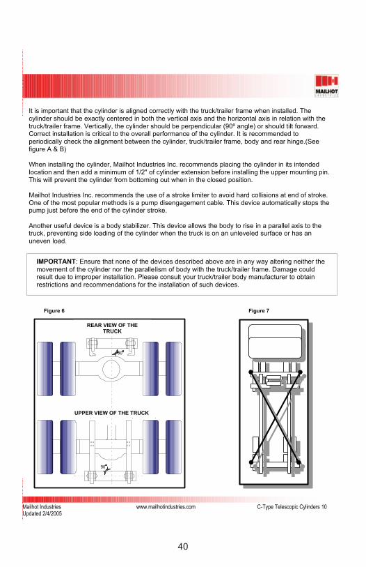
It is important that the cylinder is aligned correctly with the truck/trailer frame when installed. The cylinder should be exactly centered in both the vertical axis and the horizontal axis in relation with the truck/trailer frame. Vertically, the cylinder should be perpendicular (90º angle) or should tilt forward. Correct installation is critical to the overall performance of the cylinder. It is recommended to periodically check the alignment between the cylinder, truck/trailer frame, body and rear hinge.(See figure A & B)
When installing the cylinder, Mailhot Industries Inc. recommends placing the cylinder in its intended location and then add a minimum of 1/2" of cylinder extension before installing the upper mounting pin.This will prevent the cylinder from bottoming out when in the closed position.
Mailhot Industries Inc. recommends the use of a stroke limiter to avoid hard collisions at end of stroke. One of the most popular methods is a pump disengagement cable. This device automatically stops the pump just before the end of the cylinder stroke.
Another useful device is a body stabilizer. This device allows the body to rise in a parallel axis to the truck, preventing side loading of the cylinder when the truck is on an unleveled surface or has an uneven load.
REAR VIEW OF THE TRUCK
UPPER VIEW OF THE TRUCK
Figure 6 Figure 7

41
Mailhot Industries www.mailhotindustries.com C-Type Telescopic Cylinders 11Updated 2/4/2005
Tools to Service Your Telescopic Cylinder
When the cylinder is removed from the truck, it is suggested to use the following tools to disassemble and assemble it.
Figure 8: Metal brush
Figure 9: Mechanic type hammer
Figure 10: ViseGrip chain wrench
Figure 11: Seal hook
Figure 12: Drill and drill bits
Figure 13: Electrical contact cleaner
o Figure 14: Screwdriver with a flat rounded tip
o Figure 15: Mailhot key (wrench)
o Figure 16: 3/16” pointed punch
o Figure 17: 3/16” flatted punch
Non-illustrated: Thread sealant (Loctite 565) and Bond glue (Loctite 222)
Figure 8 Figure 9 Figure 10
Figure 11 Figure 12 Figure 13
TOOLS TO SERVICE YOUR TELESCOPIC CYLINDER

42
Mailhot Industries www.mailhotindustries.com C-Type Telescopic Cylinders 12Updated 2/4/2005
Figure 14 Figure 15 Figure 16
Figure 17
43
Mailhot Industries www.mailhotindustries.com C-Type Telescopic Cylinders 13Updated 2/4/2005
Disassembly, Assembly, Test and Bleeding Procedure
Step 1:WARNING: Before starting to remove the cylinder from the truck/trailer, take all necessary safetyprecautions and be sure to install a blocking device to prevent the box from coming down.
Stop the box in open position. Remove the upper mounting pin. Retract the cylinder. Support thecylinder and remove the lower mounting pin at the base and remove the cylinder from the truck/trailer.
WARNING: Be careful when removing oil hoses, residual pressure can be present in the cylinder or in the hydraulic system.
After the cylinder has been removed from the truck/trailer, place the cylinder where it will be able to reach full extension without any obstacle. Caution: the stand or bench where the cylinder will be serviced must be capable of holding the weight. If you have a hydraulic bench, be sure that the jaws or any other object will not damage the stages of the cylinder.
Step 2:Verify that the cylinder does not contain any oil pressure and all oil ports are clear, the air bleeder (if equipped) as well as the grease nipple on the upper attachment must be removed.
The single acting model is equipped with a sleeve over the upper stages. This has to be removed.Run a metal ring of adequate diameter on the cylinder, from the base until it reaches the sleeve. Using a hammer (plastic is recommended) hit the ring all around in order to remove the sleeve.
NOTE: Because all of the stages are to be pulled apart from the cylinder, it is important to leave adequate space on the extension side of the cylinder to avoid an accident.
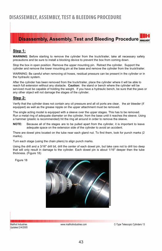
There are dowel pins located on the tube near each gland nut. To find them, look for punch marks (2 marks).
Turn each stage (using the chain pliers) to align punch marks.
Using the drill and a 3/16" drill bit, drill the center of each dowel pin, but take care not to drill too deep that will only result in damage to the cylinder. Each dowel pin is about 1/16" deeper then the tube thickness. (Figure 18)
Figure 18
DISASSEMBLY, ASSEMBLY, TEST & BLEEDING PROCEDURE
44
Mailhot Industries www.mailhotindustries.com C-Type Telescopic Cylinders 14Updated 2/4/2005
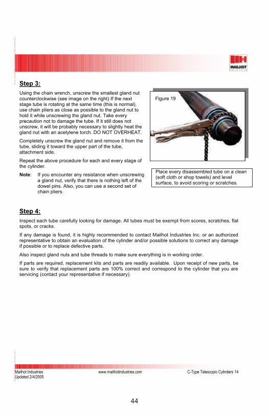
Step 3:Using the chain wrench, unscrew the smallest gland nut counterclockwise (see image on the right) If the nextstage tube is rotating at the same time (this is normal), use chain pliers as close as possible to the gland nut to hold it while unscrewing the gland nut. Take every precaution not to damage the tube. If it still does not unscrew, it will be probably necessary to slightly heat the gland nut with an acetylene torch. DO NOT OVERHEAT.
Completely unscrew the gland nut and remove it from the tube, sliding it toward the upper part of the tube, attachment side.
Repeat the above procedure for each and every stage of the cylinder.
Note: If you encounter any resistance when unscrewing a gland nut, verify that there is nothing left of the dowel pins. Also, you can use a second set of chain pliers.
Step 4:Inspect each tube carefully looking for damage. All tubes must be exempt from scores, scratches, flat spots, or cracks.
If any damage is found, it is highly recommended to contact Mailhot Industries Inc. or an authorized representative to obtain an evaluation of the cylinder and/or possible solutions to correct any damage if possible or to replace defective parts.
Also inspect gland nuts and tube threads to make sure everything is in working order.
If parts are required, replacement kits and parts are readily available. Upon receipt of new parts, be sure to verify that replacement parts are 100% correct and correspond to the cylinder that you are servicing (contact your representative if necessary).
Place every disassembled tube on a clean (soft cloth or shop towels) and levelsurface, to avoid scoring or scratches.
Figure 19

45
Mailhot Industries www.mailhotindustries.com C-Type Telescopic Cylinders 15Updated 2/4/2005
Step 5:To remove the wiper, take a flat screwdriver and insert the tipbetween the outer lip and the edge of the gland nut (Figure 20)and insert the seal hook to pull off the wiper.
Repeat the same operation with the seal hook and thescrewdriver to remove the u-cup from the gland nut. (Figure 21)
Normally, these parts should be removed by hand but it ispossible that one or more parts are jammed in the head or the gland nut so the seal would be sturdy. If this is the case, use a
flat screwdriver with a rounded tip to get under each of theseparts. WARNING: Be careful not to score the seal groove when removing the seals.
Replace the u-cup with a new one. Finally replace the wipermaking sure the lip is facing out of the gland nut (upper side).
Turn the gland nut upside down and take off the O-ring and thebackup ring as well (Figure 22). Replace with new ones.(Complete seal kit should be changed (Figure 23))
Repeat this step for each gland nut of the cylinder.
Step 4:
Figure 20
Figure 21
Figure 22 Figure 23

46
Mailhot Industries www.mailhotindustries.com C-Type Telescopic Cylinders 16Updated 2/4/2005
Step 6:
To put the cylinder back together, install the base tube in the jaw of the hydraulic bench (if you have one) otherwise,secure the tube in a sturdy device to hold it in place. DO NOT squeeze the tube too much; this could make the tube out of round.
Thoroughly inspect the inside of the tube, particularly where the dowel pin was when the cylinder was taken apart.Remove any metal residue from drilling or metal filings aswell. Apply grease at the very end of the threads. (Figure 24)
Insert the first section (next tube) in the base section and push it in approximately half way. Be sure to keep the section inserted as parallel as possible.
Install a sleeve (if available) on the threads of the sectionnewly installed (Figure 25). Take the gland nut corresponding to the section that was just inserted and apply grease to it,specifically where the seal assembly is. Hydraulic oil solublegrease is strongly recommended.
Insert the gland nut, keeping it as parallel to the tube as possible. Threads must be inserted first. After insertion, place the palm of your hands on each outer front side of the nut and slightly rotate, push in the nut until the threads can be engaged on the bigger tube. If too tight, a plastic hammer can be used (Figure 26).
Also, if the gland is too hard to move easily on the tube, install the chain pliers on it. This will give you the grip to move it along the tube.
Figure 24
Figure 25
Figure 26

47
Mailhot Industries www.mailhotindustries.com C-Type Telescopic Cylinders 17Updated 2/4/2005
Step 7:Before starting to screw the nut, clean it with an electrical cleaner spray or with a cleaner that evaporates after cleaning. If necessary, use a metal brush to remove any particles from the threads.
Begin threading with chain pliers and then apply thread sealant (Loctite565), approximately 3 inch long patch (Figure 27). Tighten the gland nut with chain pliers (Figure 28).
For stages equipped with a dowel pin, drill a 3/16” diameter hole in the tube at 180 degrees from the previous dowel pin (Image C), the depth should be only 1/16" into the gland nut. Put a drop of bond glue (Loctite 222) in the newly made hole. Insert a new dowel pin and hammer the dowel pin until it is flat with the tube surface (Be careful not to damage the tube. Using the pointed punch, push somemetal toward the dowel pin on each side (Figure 29).
Repeat steps 5, 6 and 7 for all stages of the cylinder.
Figure 27 Figure 28
Figure 29 Figure 30

48
Mailhot Industries www.mailhotindustries.com C-Type Telescopic Cylinders 18Updated 2/4/2005
Step 8:Install the sleeve over the upper stages and secure it in place using a plastic hammer. The sleeve head must rest in the groove. If too loose or badly damaged, this part should be replaced. Contact your Mailhot Industries representative.
Finally, install and tighten the air bleeder (if equipped).
Install the cylinder on the truck.
Connect the cylinder to the hose(s).
If equipped with an air bleeder: The last step is to bleed any air that could be trapped in the cylinder. Fully extend the cylinder (dump body/trailer should be empty) for the first time. Then lower the cylinder to within a foot of the frame. Turn the bleeder in a counterclockwise direction, this opens the valve and will allow air to escape. When a steady flow of oil comes from the bleeder, turn the valve clockwise until the valve is closed.
49
Mailhot Industries www.mailhotindustries.com C-Type Telescopic Cylinders 19Updated 2/4/2005
Troubleshooting
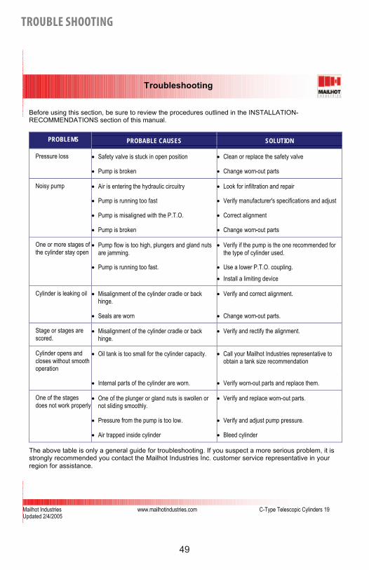
Before using this section, be sure to review the procedures outlined in the INSTALLATION-RECOMMENDATIONS section of this manual.
PROBLEMS PROBABLE CAUSES SOLUTION
Pressure loss • Safety valve is stuck in open position • Clean or replace the safety valve
• Pump is broken • Change worn-out parts
Noisy pump • Air is entering the hydraulic circuitry • Look for infiltration and repair
• Pump is running too fast • Verify manufacturer's specifications and adjust
• Pump is misaligned with the P.T.O. • Correct alignment
• Pump is broken • Change worn-out parts
One or more stages of the cylinder stay open
• Pump flow is too high, plungers and gland nuts are jamming.
• Verify if the pump is the one recommended for the type of cylinder used.
• Pump is running too fast. • Use a lower P.T.O. coupling.• Install a limiting device
Cylinder is leaking oil • Misalignment of the cylinder cradle or back hinge.
• Verify and correct alignment.
• Seals are worn • Change worn-out parts.
Stage or stages are scored.
• Misalignment of the cylinder cradle or back hinge.
• Verify and rectify the alignment.
Cylinder opens and closes without smooth operation
• Oil tank is too small for the cylinder capacity. • Call your Mailhot Industries representative to obtain a tank size recommendation
• Internal parts of the cylinder are worn. • Verify worn-out parts and replace them.
One of the stages does not work properly
• One of the plunger or gland nuts is swollen or not sliding smoothly.
• Verify and replace worn-out parts.
• Pressure from the pump is too low. • Verify and adjust pump pressure.
• Air trapped inside cylinder • Bleed cylinder
The above table is only a general guide for troubleshooting. If you suspect a more serious problem, it is strongly recommended you contact the Mailhot Industries Inc. customer service representative in your region for assistance.
TROUBLE SHOOTING
50
Mailhot Industries www.mailhotindustries.com C-Type Telescopic Cylinders 20Updated 2/4/2005
Warranty
A) DURATIONMailhot Industries Inc. warranty starts at the date of invoice:
1. Non-nitrided cylinders and components, Mailhot branded hydraulic components and nitrided cylinder's components are covered with a one (1) year period against manufacturing defects or raw material defect.
2. Nitrided cylinders are covered for a two (2) year period against all manufacturing or material defects.
B) COVERAGE1. Warranty mentioned in paragraph A applies to defective parts only and actual work done on
those parts by Mailhot Industries Inc. employees, at a designated and authorized Mailhot Industries service center, or by a third party, provided there is an agreement between Mailhot Industries Inc. and the buyer. In all these cases, a Return Goods Authorization (R.G.A.) number must be issued by Mailhot Industries Inc. or its authorized representative. Notwithstanding the above, Mailhot Industries Inc. reserves the right to replace, in all or in part, or to credit product covered by this warranty.
2. Costs and expenditures caused by the removal and reinstallation of the defective productfrom "Mailhot Industries Inc" are at the buyer's expense. If the product is defective and this defectiveness is covered by the present warranty, Mailhot Industries Inc. will reimburse tothe buyer costs according to the agreement negotiated when the Return GoodsAuthorization number was issued.
3. This warranty is ruled with a maximal workmanship allowance according to the case andregion. You must call Mailhot Industries Inc. to get all details.
4. All product must be returned to Mailhot Industries Inc. or its authorized representative using ground transportation and prepaid. If the product is defective and this defectiveness iscovered with the present warranty, Mailhot Industries Inc will reimburse to the buyer costs of transport as agreed when the Returned Merchandise Authorization number was issued.
C) NON COVERAGE (EXCLUSIONS)This Mailhot Industries Inc. warranty does not apply to:
1. Modification on Mailhot hydraulic components, cylinder and/or it's components;2. Bad maintenance on Mailhot hydraulic components, cylinder and/or it's components;3. Abusive use of Mailhot hydraulic components, cylinder and/or it's components;4. Installation or use not according to instructions supplied in maintenance manual for the
purchased product;5. Use of Mailhot hydraulic components and/or cylinder and/or components after a defect has
been found, a functional defect or any defect that would interfere with the normal use;6. Any non-authorized repair of a Mailhot component and/or cylinder and/or it's components;7. Any damage or defect caused by an impact or accident on the vehicle or the equipment
where the Mailhot component and/or cylinder and/or it's component was installed;8. Any Mailhot hydraulic components, cylinder and/or it's components working under excessive
working pressure specified by Mailhot Industries Inc.;9. Any Mailhot hydraulic components, cylinder and/or it's components within an hydraulic
system not equipped with a filtering system as described in the maintenance manual;10. Any traveling fees from the buyer to verify a related problem to the Mailhot hydraulic
components, cylinder and/or it's components;11. Any expenses for lubricant or workshop expenditures
WARRANTY

51
Mailhot Industries www.mailhotindustries.com C-Type Telescopic Cylinders 21Updated 2/4/2005
12. Any expenses for repainting a Mailhot hydraulic components, cylinder and/or it's components 13. Failing to report within 30 days to Mailhot Industries Inc. or it's authorized representative
about the knowledge of a defect or breakage of a Mailhot hydraulic components, cylinderand/or it's components;
14. Normal wear of seals or wear caused by contamination.15. Inadequate warehousing of the product (refer to the maintenance manual)
D) RESPONSIBILITY EXCLUSIONMailhot Industries Inc. will not be liable for the consequential damages or contingent liabilities, including, but not limited to, loss of life, personal injury, loss of business income, downtime costs and trade, or other commercial loss arising out of the failure of Mailhot cylinder or hydraulic component covered by present warranty.
E) ELECTED PLACE OF RESIDENCEMailhot Industries Inc. and the buyer agree, for any and all claims, or lawsuit for any reason whatsoever, in relation with present agreement, to choose the law district of Joliette, province of Quebec, Canada, as the proper place of auditions of claims or lawsuits to the exclusion of any other law district that could have jurisdiction on such claims or lawsuit, as prescribed by the law.
52
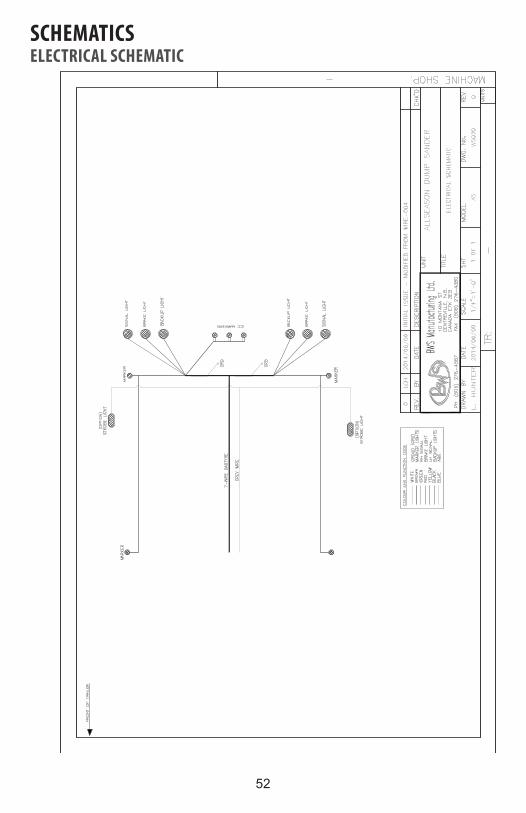
SCHEMATICSELECTRICAL SCHEMATIC
53
AIR SCHEMATIC
FRO
NT
OF
TRU
CK
1
3
AIR
CYL
IND
ER
1 4 AIR
TEE
AIR
VAL
VE1 4 T
UBE
TO
1 8 NPT
90
DEG
REE
4010
68
0711
6
4010
6807
027
3 4 5 9 11761 2
DES
CR
IPTI
ON
P/N
#1 3Q
'TY
11
108
1 4 TU
BE T
O 1 4 N
PT 9
0 D
EGR
EE07
133
2
12
NO
TES:
1) T
HIS
IS A
GEN
ERAL
LAY
OU
T W
HIC
H S
HO
WS
STAN
DAR
D A
ND
CO
MM
ON
LYO
PTIO
NED
CO
MPO
NEN
TS.
2) L
OC
ATIO
N O
F C
ERTA
IN C
OM
PON
ENTS
MAY
VAR
Y BY
TR
AILE
R. S
OM
EO
PTIO
NAL
CO
MPO
NEN
TS M
AY N
OT
BE S
HO
WN
.3)
SO
ME
PAR
TS S
UC
H A
S VA
LVES
VAR
Y BY
TR
AILE
R. C
HEC
K PA
RT
NU
MBE
RW
ITH
BW
S PA
RTS
DEP
ARTM
ENT
BEFO
RE
OR
DER
ING
REP
LAC
EMEN
TS.
4) S
USP
ENSI
ON
AIR
BAG
S VA
RY
BY T
RAI
LER
MO
DEL
BAS
ED O
N L
OAD
CAP
ACIT
Y AN
D R
IDE
HEI
GH
T.
13 14 15 16 172
2
TAIL
GAT
E LO
CK
AIR
CYL
IND
ER
AIR
RID
E SE
AT
2
5
44

54
HYDRAULIC SCHEMATIC

55ALL SEASON SANDER
TROUBLE SHOOTINGPROBLEM POSSIBLE SOLUTIONS
Spinner not turning Check spinner drive assembly and keys.
Check for motor rotation.
Check motor shaft key to see if the key was sheared off.
Conveyor is not operating. Check for anything jammed in the conveyor chain.
Check gearbox drive shaft to conveyor for rotation.
If shaft is not turning check for gear box damage.
Remove motor from gear box to see if motor shaft key is sheared.
Check if motor shaft is turning.
None of the hydraulic circuits are working.
Shut down the truck as soon as it is safe to do so. Check under the truck for hydraulic oil. If there isn't oil under the truck, install pressure gauge at the test port on the valve box. If there is no pressure shown on the gauge there is a possible pump or electrical failure.Check main power fuse under drivers seat this is the main power supply to the control valve and cab controls.

56ALL SEASON SANDER
WARRANTYBWS ALL SEASON SANDER WARRANTY AGREEMENTThis is a legal contract between the original owner, BWS Manufacturing Ltd. and the retailing BWS Authorized Representative/Dealership.
1 YEAR BASIC WARRANTYExcept for exclusions specified below, BWS Manufacturing Ltd. warrants that the specified BWS equipment herein will be free from defects in materials and workmanship, under normal use and service, for the period of the first 12 months of regular service post the date-in-service. This warranty extends only to the original 1st owner. It is not transferable and applies only to OEM installed components & equipment.
EXTENDED BWS FRAME SUPER STRUCTURE WARRANTY COVERAGEIn addition to the above prescribed 12 month warranty period, BWS Manufacturing Ltd. also warrants the trailer main frame beams or ‘super-structure’ (consisting of the top & bottom flanges, and their connecting web) to be free from defects in materials & workmanship, under normal use and service for a period of 5 years from the date-in-service (DIS) only to the first owner.
PAINT/FINISHGuaranteed against defects in materials & workmanship for 3 years. Any custom colors are subject to a 1 year warranty only. Does not cover against general wear and tear such as stone chips or fade as of 2016.
Any new or used BWS equipment sold through any auction (private or public), does not qualify for any BWS Manufacturing Ltd. administered or supported warranty coverage what-so-ever.
AT THE SOLE DISCRETION OF BWS MANUFACTURING LTD.:• Your sole exclusive remedy arising from your use of this BWS equipment; is limited to the repair or
replacement, of any specified defective parts and/or materials. All warranty work is to be performed at an authorized BWS Warranty Dealer, or at the BWS Manufacturing Ltd. OEM facility (in Centreville, NB).
• Claims made from far away / remote locations may necessitate advance repair quote submissions from local & capable repair shops / facilities to be prepared for, reviewed and accepted by BWS Manufacturing Ltd., as being the best & most reasonable remedy for a given situation.
• The warranty coverage period expiry term applies fairly as to when the specified BWS equipment is brought to an authorized BWS Dealer, or to the BWS OEM facility for remedy or correction(s) of any user suspected possibly warrantable defect(s).

57ALL SEASON SANDER
EXCLUSIONS FROM BWS WARRANTY COVERAGE
THIS WARRANTY SHALL NOT APPLY TO:1. Components manufactured by persons or organizations other than BWS, when independently
warrantied by that component supplier / manufacturer beyond the 12 month BWS warranty terms period. Such as, but not limited to:
• air, electrical• hydraulic accessory systems (eg. ABS sensor alignment)
2. Any trailer/unit which shall have been operated in such a manner against the specific instructions or recommendations of BWS Manufacturing Ltd., or which shall have been neglected in regular user maintenance or used in any way deemed inappropriate to the opinion of BWS Manufacturing Ltd., consequently adversely affecting the intended performance levels.
3. Any trailer/unit to which affected original parts have been removed or altered, or had user custom alterations made, without the express written consent & approval of BWS Manufacturing Ltd.
4. Normal required regular maintenance, adjustment(s), & service.5. BWS Products operated with cargo(s)/payload(s) exceeding BWS’ rated unit capacity.6. Any freight or transportation costs associated with warranty claim(s).7. BWS is not involved in any warranty claims of any OEM installed engines.
BWS WARRANTY DISCLAIMER AND LIMITATIONS OF LIABILITYBWS Manufacturing Ltd. And the authorized dealer offer no other warranties, expressed or implied. It is agreed that neither BWS, nor the dealer shall be liable for any incidental or consequential damages.Including but not limited to:
• loss of income• damage of vehicle(s) or equipment• damage to attachments• damage to cargo• towing expenses• attorney fees• liability you may have in respect to any other person or party
TIME LIMIT ON COMMENCING LEGAL ACTIONIt is agreed that you have one (1) year from the accrual of the cause of action to commence any legal action, arising from the purchase or use of the specified BWS equipment or be barred forever. To the extent any provision of this warranty contravenes the law of an affected local legal jurisdiction, such provision shall be inapplicable in such jurisdiction, and the remainder of the warranty shall not be affected thereby.On the date of sale, I have read the complete BWS Warranty Agreement, I understand its terms & conditions, and acknowledge receipt of my copy of this agreement.

58ALL SEASON SANDER
WARRANTY REGISTRATION FORM
Please print clearly or type.
___________________________ __________________________________date of sale BWS serial #___________________________ __________________________________date of delivery BWS Model______________________________________ __________________________________purchaser name purchaser title /position within the company______________________________________purchaser signature
__________________________________________________________________________purchaser/company name __________________________________________________________________________ship to address city/town __________________________________________________________________________province/state postal/zip code
__________________________________________________________________________dealership name_____________________________________ __________________________________primary contact at the dealership primary contact phone__________________________________________________________________________ship to address city/town __________________________________________________________________________province/state postal/zip code
Please record required information and submit to BWS Warranty Department. Email [email protected] or fax (506) 276-4380. Make certain to provide a copy to the customer/trailer purchaser and keep a copy at the dealer office.
59ALL SEASON SANDER
The following items are to be performed by the dealer at the time of delivery. Customer is to review and sign off each item as verification that it was performed.
Completed the BWS Warranty Registration Form
Explain required maintenance program to Customer.
Review operation and service manual with the Customer.
Explain the BWS warranty to the Customer
Explain and demonstrate the equipment operation to the Customer.
Present completed warranty registration copy to the Customer and fax copy to BWS Warranty Department.
FOR ASSISTANCE, PLEASE CALL SERVICE Monday - Friday 8:00am - 5:00pm AST
Toll Free (888) 896-5777Phone (506) 276-4567 Email: [email protected]
STRUCTURAL & COMPONENT WARRANTIESNo warranty what-so-ever on tires or ABS sensor alignment.1 year complete - 100% Parts and Labour (from the In Service Date)
BWS CONTACT INFORMATION 29 Hawkins Road, Centreville, NB E7K 1A4 Phone (506) 276-4567 Email [email protected]


![[XLS] · Web viewHOIST HOIST EQUIPMENT ACTUATOR, MLG HOIST HOIST EQUIPMENT - ACTUATOR, MLG HOIST HOIST - CARDAN PIN HOIST HOIST-CARDAN PIN HOIST HOIST-DEVICE,FLAP TRACK 2-5 HOIST](https://static.fdocuments.us/doc/165x107/5b1fa5177f8b9aa64c8b4800/xls-web-viewhoist-hoist-equipment-actuator-mlg-hoist-hoist-equipment-actuator.jpg)