General License Class Chapter 6 - Antennas
61
General License Class Chapter 6 - Antennas Bob – KA9BHD Eric – K9VIC
Transcript of General License Class Chapter 6 - Antennas

General License ClassChapter 6 - Antennas
Bob – KA9BHD
Eric – K9VIC

Learning ObjectivesLearning Objectives
• Teach you enough to get all the antenna questions right during the VE Session
• Learn a few things from you about antennas and your experiences
• Un-teach you a few things you might have picked up from ‘friendly’ sources on the repeater
• Have fun (it’s a hobby, right?)• Finish before noon

VE Session
• Total of 4 questions from this chapter
• One each in these areas:– Feedlines, Characteristic Impedance and
Attenuation, SWR Calculation and Measurement and effects, Matching Networks
– Basic Antennas
– Directional Antennas
– Specialized Antennas

Feedlines
• Coax
• Twin Lead
• Ladder Line

Feedlines
• Coax– For amateur use, 50 and 75 Ohm typical– Impedance determined by size and spacing of
conductors, and the type of dielectric– Unbalanced– Convenient
• Impedance matches most modern radios• Physical routing easy
– Losses (dB/100 ft.) increase with increased SWR and frequency
Feedlines
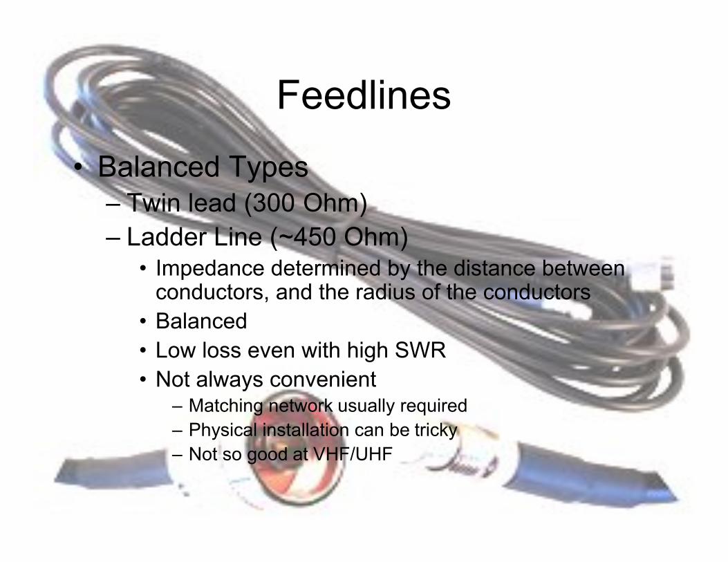
• Balanced Types– Twin lead (300 Ohm)– Ladder Line (~450 Ohm)
• Impedance determined by the distance between conductors, and the radius of the conductors
• Balanced• Low loss even with high SWR• Not always convenient
– Matching network usually required– Physical installation can be tricky– Not so good at VHF/UHF

Feedlines
• SWR (Standing Wave Ratio)– Caused by reflection of RF at impedance
mismatch
– Expressed as a ratio, always 1:1 or greater
– Cannot be eliminated by using a tuner at the radio end of the line
– Calculated by taking a ratio of impedances
TerminologyTerminology
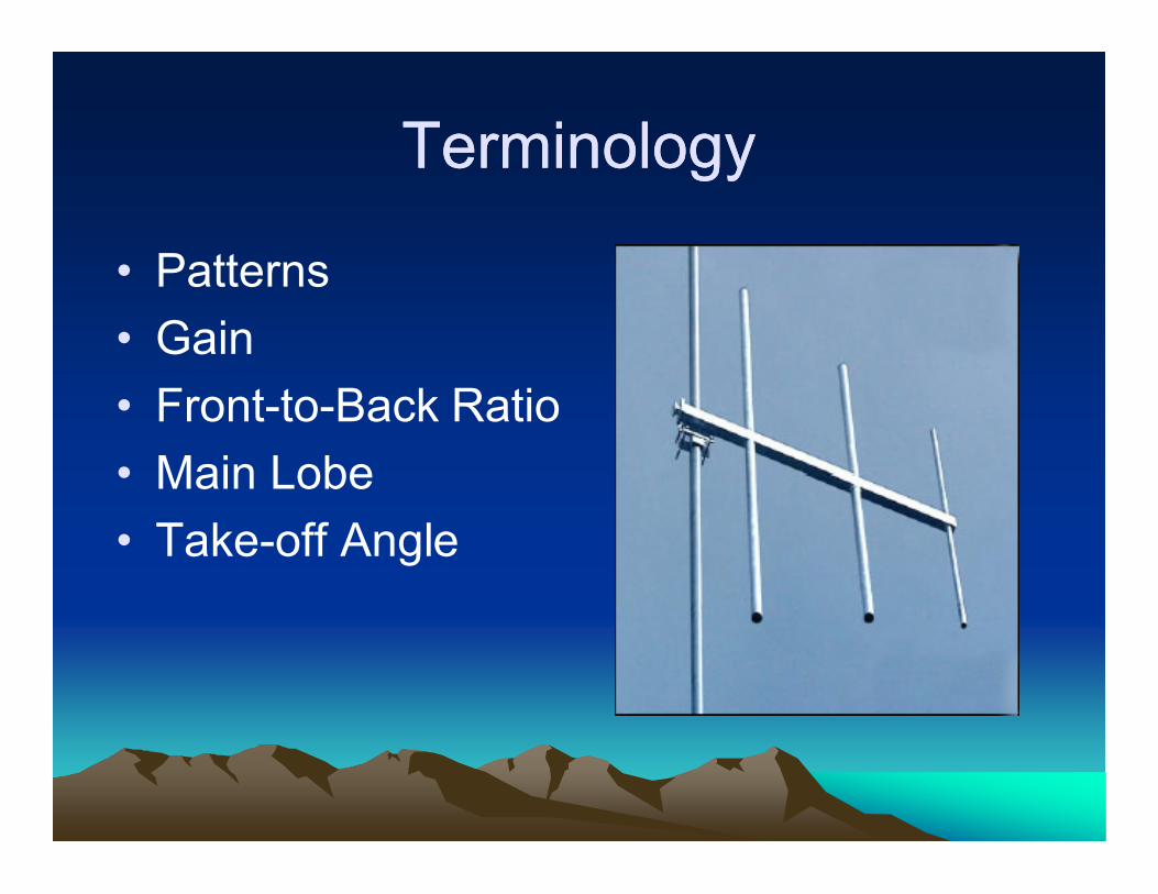
• Patterns
• Gain
• Front-to-Back Ratio
• Main Lobe
• Take-off Angle
TerminologyTerminology
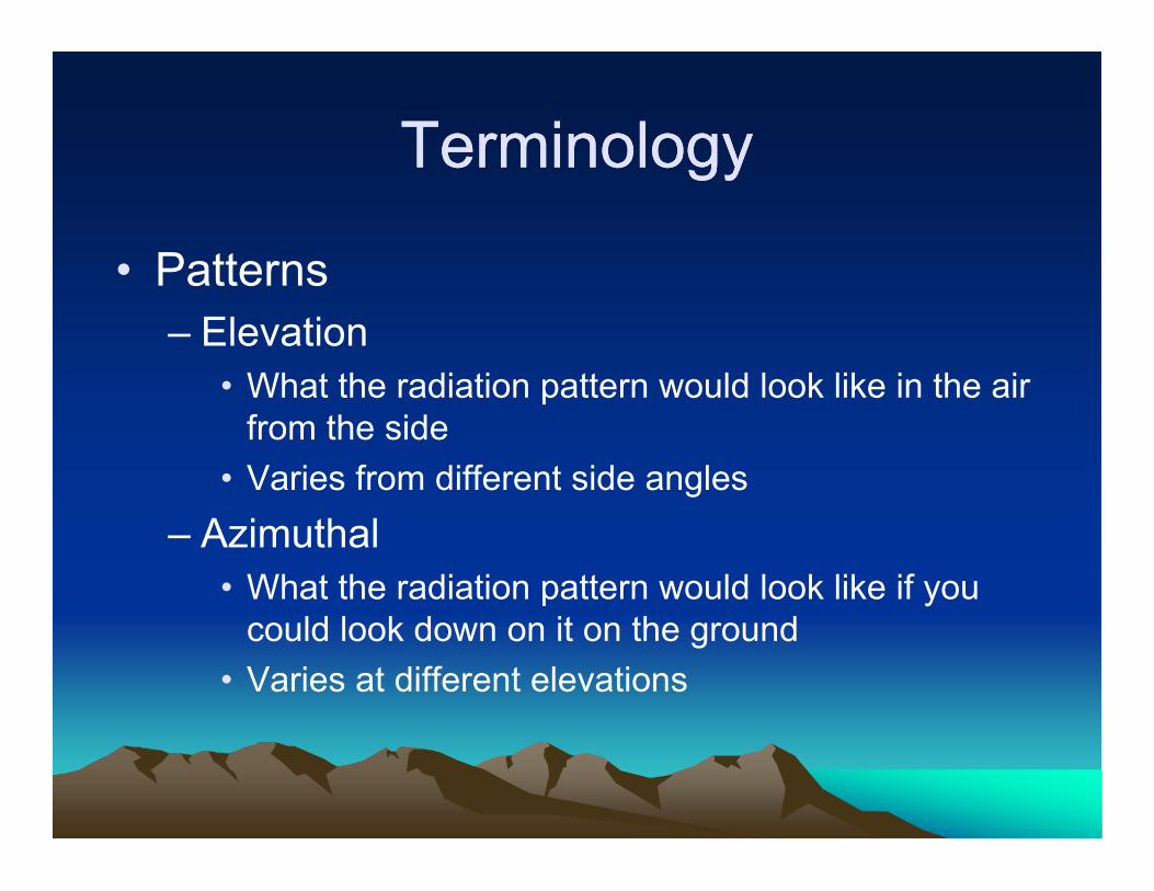
• Patterns– Elevation
• What the radiation pattern would look like in the air from the side
• Varies from different side angles
– Azimuthal• What the radiation pattern would look like if you
could look down on it on the ground
• Varies at different elevations

Terminology
Two Plots of the same antenna:
Elevation Azimuth
TerminologyTerminology
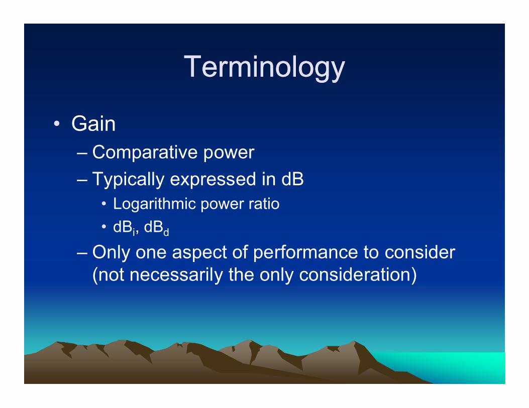
• Gain– Comparative power
– Typically expressed in dB• Logarithmic power ratio
• dBi, dBd
– Only one aspect of performance to consider (not necessarily the only consideration)

Terminology
• Gain (where does it come from?)

Terminology
• Front-to-back ratio

Terminology
• Main Lobe

Terminology
• Take-off Angle

TerminologyTerminology
• What’s as important as gain figures?– F/B Ratio
– Source (feedpoint) impedance
– Take-off angle (usually varies with height, not antenna design)
– Performance over what frequencies?
– Example

A Tale of Two Antennas

A Tale of Two Antennas
Antenna A Antenna B
Gain (dBi) 11.10 11.87
F/B (dB) 11.47 17.17
Beam Width 72.6° 68.8°

A Tale of Two Antennas
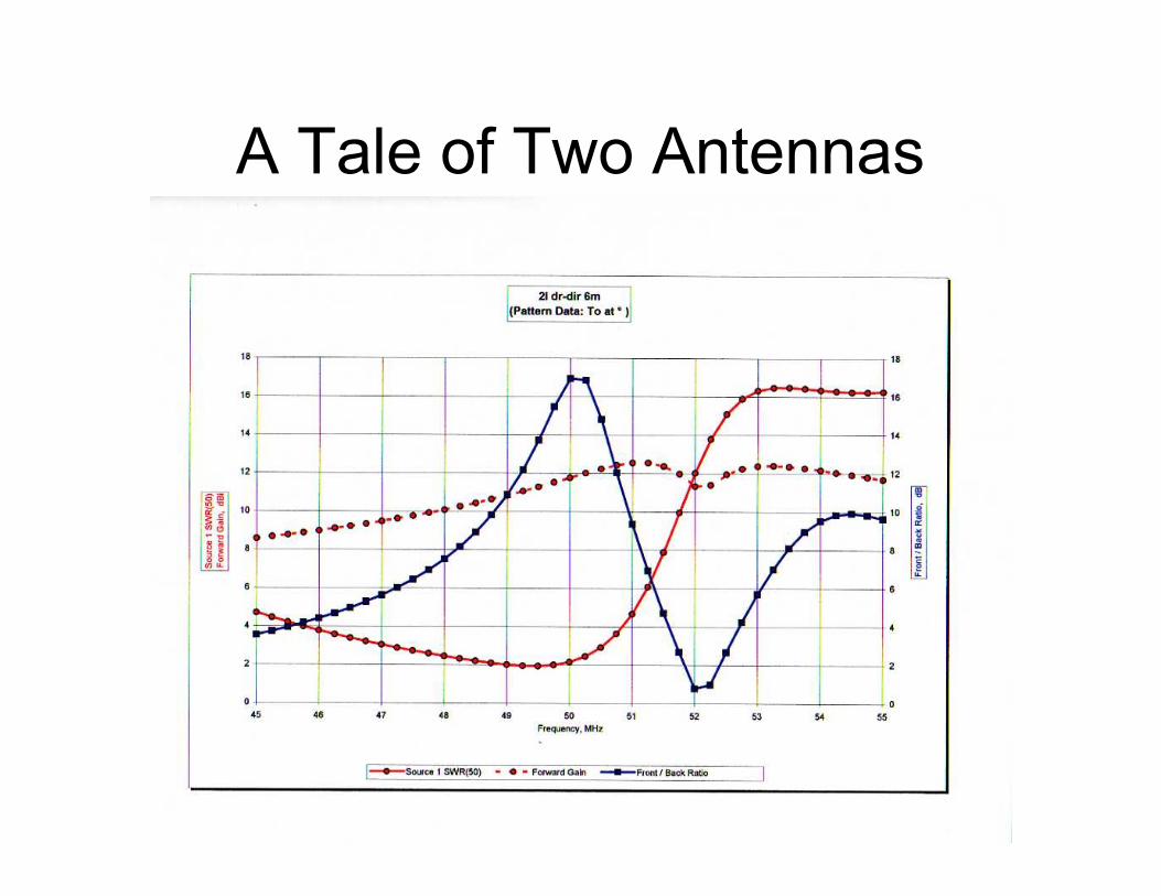
A Tale of Two Antennas
Basic AntennasBasic Antennas
• Random wire (not long wire)
• Ground plane (vertical monopole)
• Ground mounted vertical
• Dipole (vs. doublet)

Basic AntennasBasic Antennas
• Random wire– Advantages
• Cheap
• Can be put just about anywhere
– Disadvantages• Radiation pattern unpredictable
• Requires remote match or leaves RF in the shack
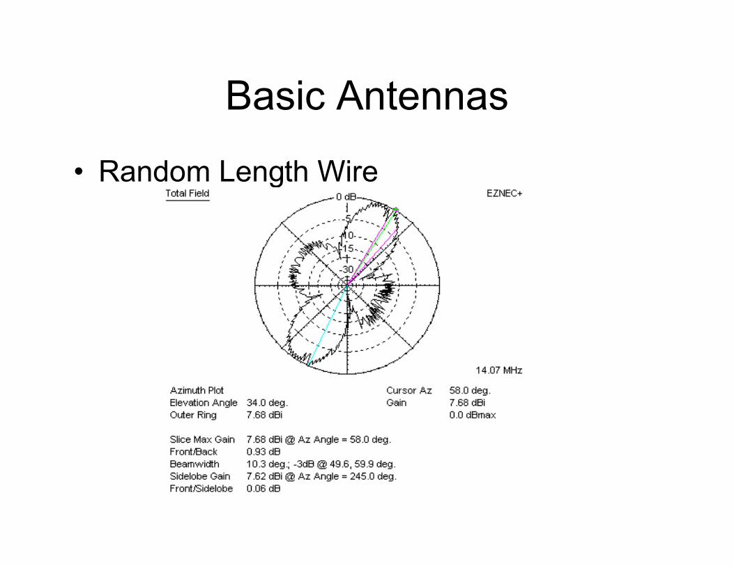
Basic Antennas
• Random Length Wire
Basic AntennasBasic Antennas
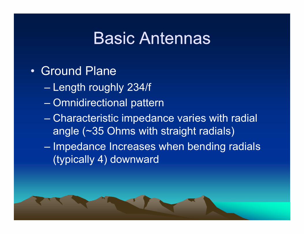
• Ground Plane– Length roughly 234/f
– Omnidirectional pattern
– Characteristic impedance varies with radial angle (~35 Ohms with straight radials)
– Impedance Increases when bending radials (typically 4) downward

Basic Antennas
• Ground Plane
Basic AntennasBasic Antennas
• Ground Plane– What do the radials actually do?
– Are they passive?
– Do they radiate?

Basic Antennas
• Ground Plane
showing
currents

Basic Antennas
• Ground Plane
Basic Antennas
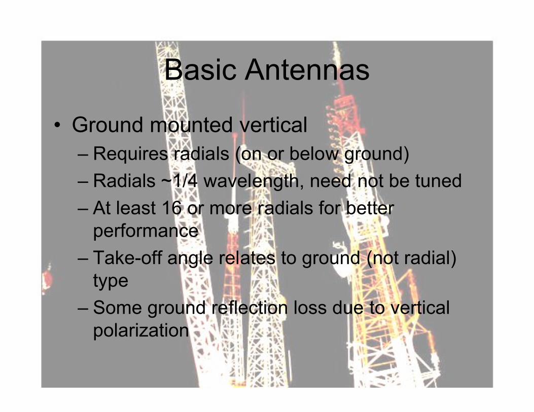
• Ground mounted vertical– Requires radials (on or below ground)
– Radials ~1/4 wavelength, need not be tuned
– At least 16 or more radials for better performance
– Take-off angle relates to ground (not radial) type
– Some ground reflection loss due to vertical polarization
Basic AntennasBasic Antennas
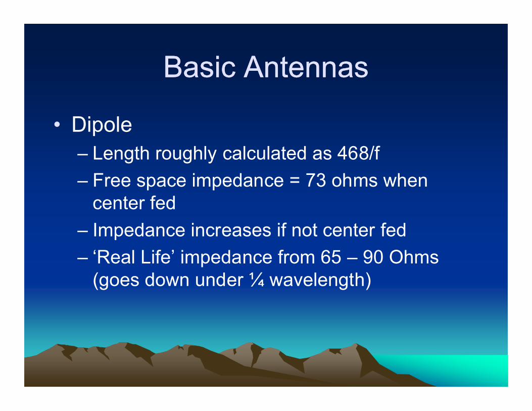
• Dipole– Length roughly calculated as 468/f
– Free space impedance = 73 ohms when center fed
– Impedance increases if not center fed
– ‘Real Life’ impedance from 65 – 90 Ohms (goes down under ¼ wavelength)

Basic Antennas

Basic Antennas
• Dipole at 1/2 wavelength
Basic Antennas
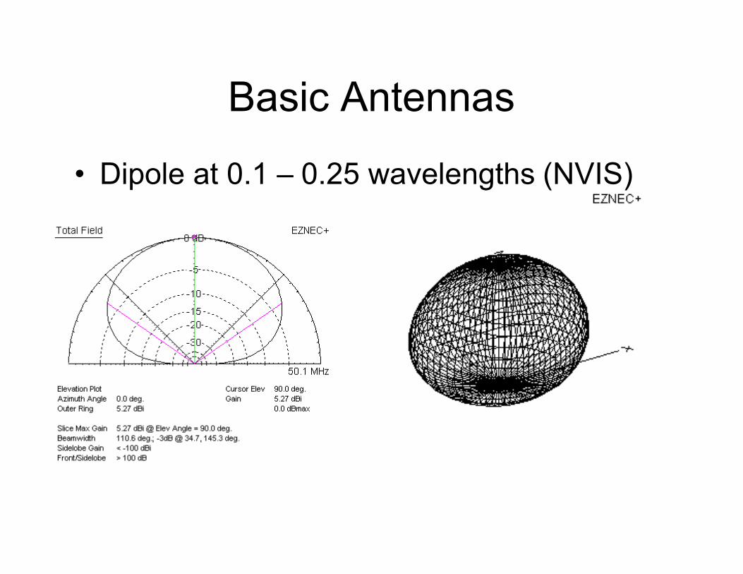
• Dipole at 0.1 – 0.25 wavelengths (NVIS)

(Uni) Directional Antennas(Uni) Directional Antennas
• Yagi-Uda
• Cubical Quad
• Delta Loop

Directional Antennas
• Yagi-Uda

Directional AntennasDirectional Antennas
• Yagi-Uda– Driven element (DE) and some combination
of Reflector and Director(s)– Reflector slightly longer than the DE– Driven Element about ½ Wavelength– Director Shorter than the DE– More Directors (on longer boom) = more gain– DE impedance typically 35 Ohms
• Gamma match typically used to match 50 Ohm line

Directional AntennasDirectional Antennas
• Yagi-Uda– Adjustments to boom length, number of
elements, spacing of elements can be used to change:
• Gain (3-element has theoretical 9.7 dBi)
• F/B Ratio
• SWR Bandwidth– Can also be increased with fatter elements

Directional AntennasDirectional Antennas
• Yagi-Uda– Can be stacked
• Two 3-element Yagis ½ wavelength apart vertically increase gain by 3 dB
• Elevation of major lobes gets tighter (lower overall elevation pattern)

Directional Antennas
• Yagi-Uda, Stacked pattern
Directional Antennas
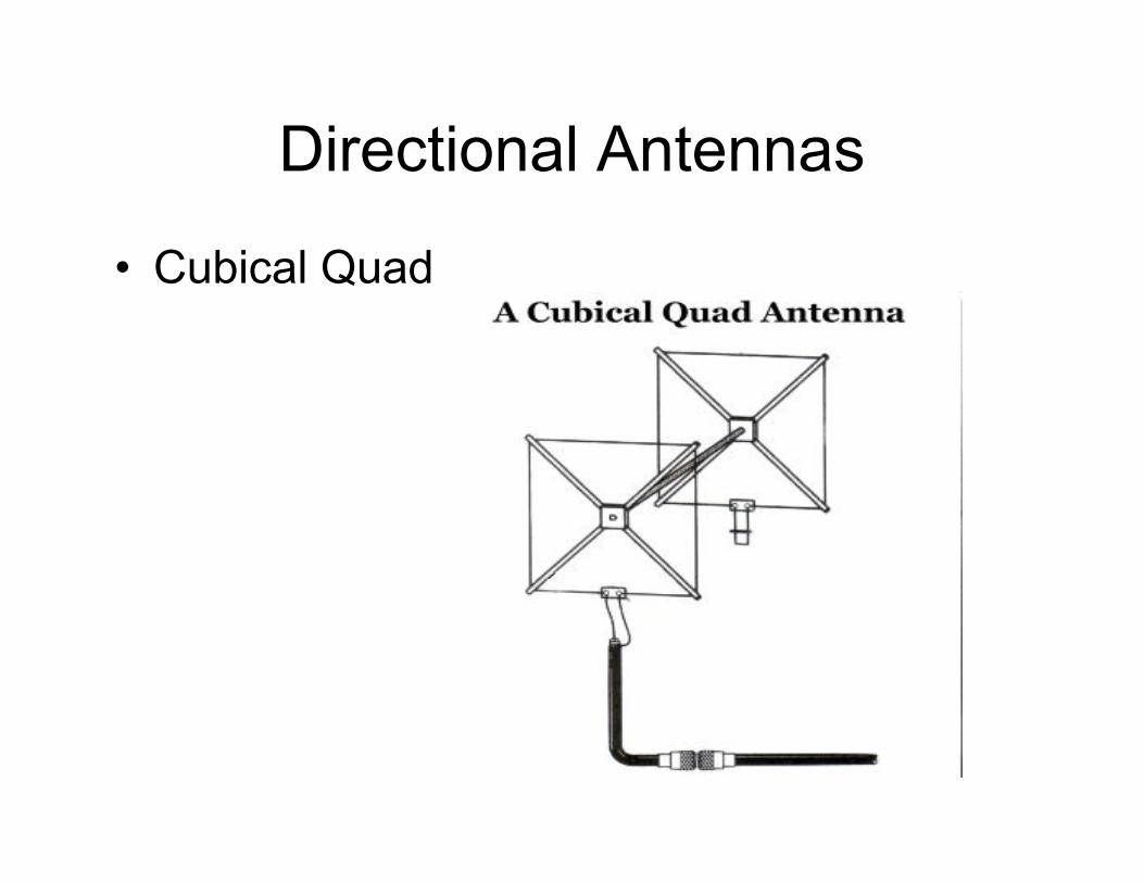
• Cubical Quad

Directional AntennasDirectional Antennas
• Cubical Quad– Driven Element (DE) and Reflector
– DE is about 1 Wavelength long
– Reflector is about 5% longer than the DE
– Spacing between elements is about 0.2 wavelengths
– Gain roughly the same as 3-element Yagi
– Feed at bottom or side
Directional Antennas
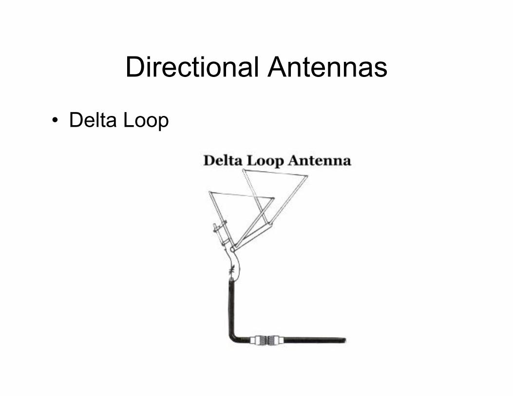
• Delta Loop

Directional AntennasDirectional Antennas
• Delta Loop– Driven Element and Reflector (triangles)
– DE about 1 Wavelength long
– Reflector about 5% longer than the DE
– Gain about the same as the quad

Specialized AntennasSpecialized Antennas
• Log Periodic Dipole Array (LPDA)
• Beverage
• Multiband Antennas
Specialized Antennas
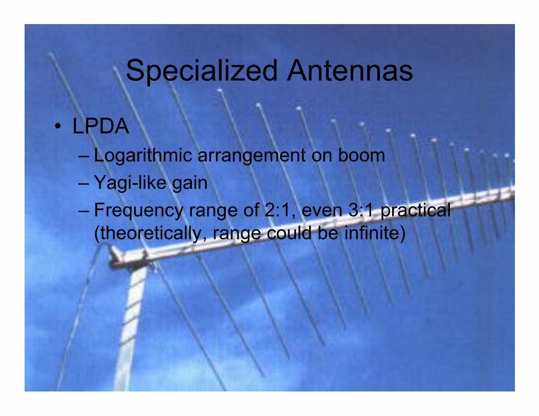
• LPDA– Logarithmic arrangement on boom
– Yagi-like gain
– Frequency range of 2:1, even 3:1 practical (theoretically, range could be infinite)
Specialized AntennasSpecialized Antennas
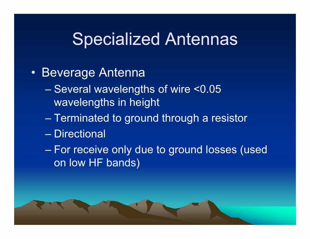
• Beverage Antenna– Several wavelengths of wire <0.05
wavelengths in height
– Terminated to ground through a resistor
– Directional
– For receive only due to ground losses (used on low HF bands)

Specialized AntennasSpecialized Antennas
• Multiband Antennas– Use traps/stubs to radiate on more than one
band• Trap is a tuned circuit
• At resonant frequency it presents high impedance
• Below resonant frequency it’s typically inductive (makes antenna shorter)
Specialized AntennasSpecialized Antennas
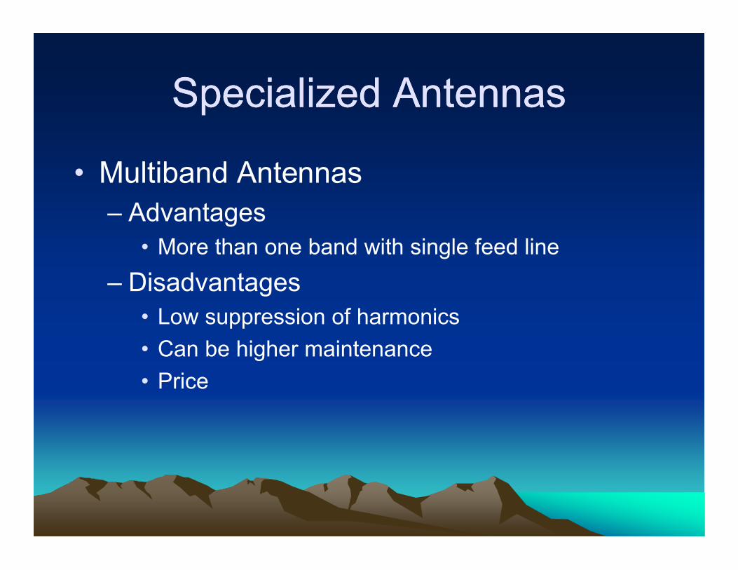
• Multiband Antennas– Advantages
• More than one band with single feed line
– Disadvantages• Low suppression of harmonics
• Can be higher maintenance
• Price

Case StudyCase Study
• Not on the exam, but good practical knowledge.
• One reason it’s good to have some knowledge of what we’ve covered here this morning.
SWR as an IndicatorSWR as an Indicator
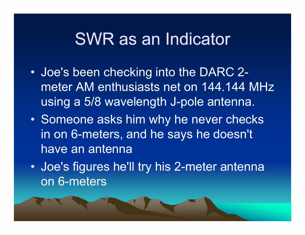
• Joe's been checking into the DARC 2-meter AM enthusiasts net on 144.144 MHz using a 5/8 wavelength J-pole antenna.
• Someone asks him why he never checks in on 6-meters, and he says he doesn't have an antenna
• Joe's figures he'll try his 2-meter antenna on 6-meters
SWR as an IndicatorSWR as an Indicator
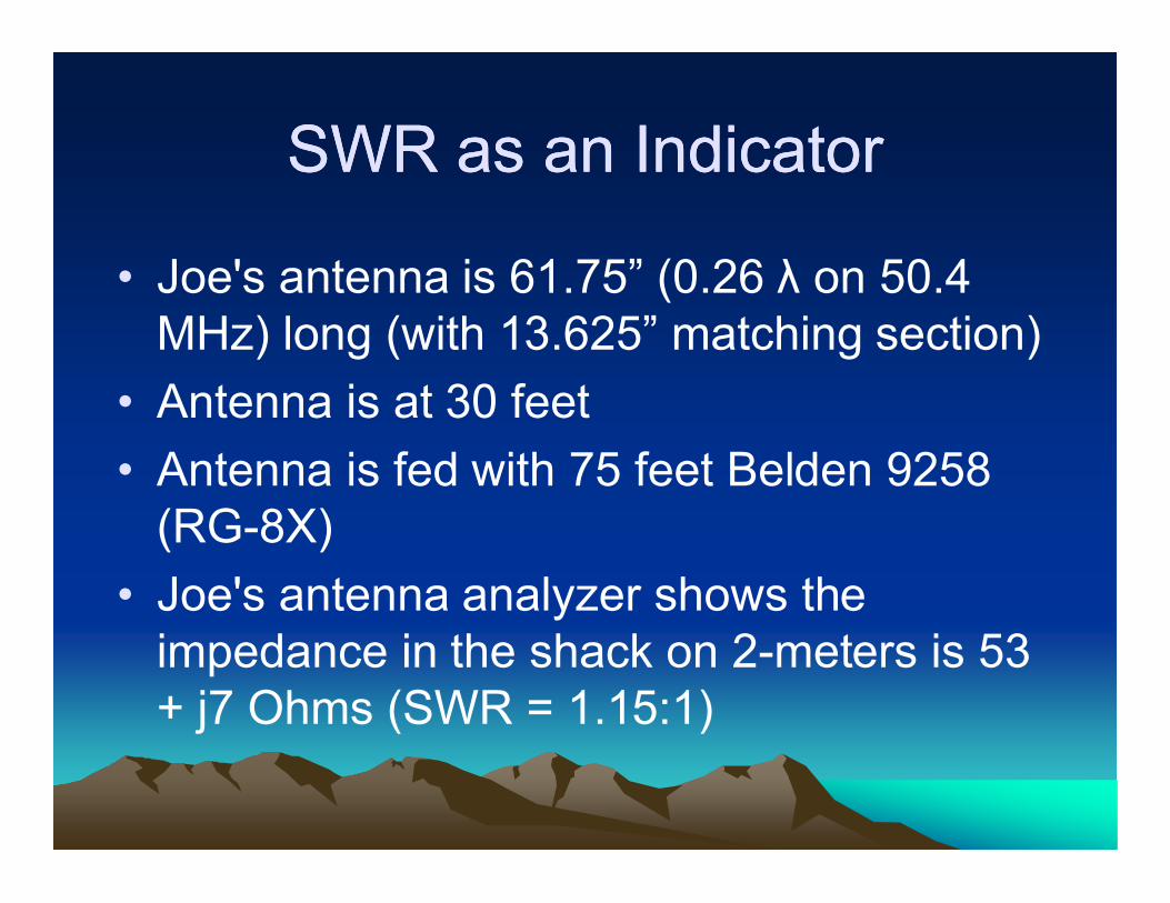
• Joe's antenna is 61.75” (0.26 λ on 50.4 MHz) long (with 13.625” matching section)
• Antenna is at 30 feet
• Antenna is fed with 75 feet Belden 9258 (RG-8X)
• Joe's antenna analyzer shows the impedance in the shack on 2-meters is 53 + j7 Ohms (SWR = 1.15:1)

SWR as an IndicatorSWR as an Indicator
• Joe measures the impedance in the shack at 50.4 MHz and finds that it's 14 +j23 Ohms (SWR = 4.4:1)
• Joe looks up loss data for his coax, and finds that 4.5:1 SWR will cause an additional 1.5 dB loss
• Joe models his antenna and finds it has 4 dBi gain at 50.4
• Joe runs 20 Watts on 6-meters; he calculates his ERP at 35.5 Watts (4 – 1.5 = 2.5 dB gain)

SWR as an IndicatorSWR as an Indicator
• Joe puts a simple L-network (loss <<1dB) in his shack, and measures the SWR at 1:1 on 50.4 MHz. He calls and calls, but he can barely hear the net, and no one can hear him trying to check in.
• What happened to poor Joe?

SWR as an IndicatorSWR as an Indicator
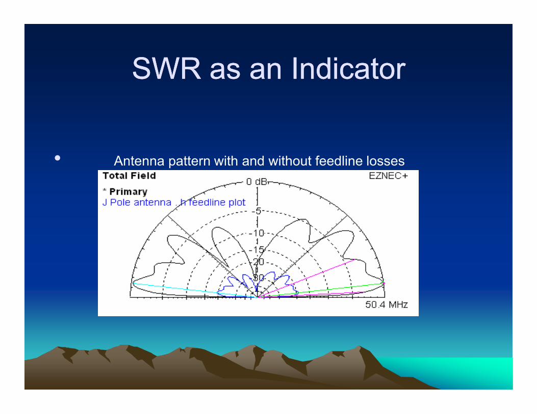
• While at 50.4 MHz the SWR in the shack was 4.4:1, at the antenna it was 263:1 (impedance = 11.6 – j440.6 Ohms)
• Line losses from SWR are 17 dB
• Matched line loss is 2 dB
• Total losses = 19 dB
SWR as an IndicatorSWR as an Indicator
• Antenna pattern with and without feedline losses

SWR as an IndicatorSWR as an Indicator
• Reasonable SWR does notindicate your antenna is
working well!
• Total power into the antenna = 0.2 Watts

SWR as an IndicatorSWR as an Indicator
• Mary has a dipole 65.5” long cut for the bottom of the FM broadcast band
• She knows the SWR at the antenna can't be measured with her SWR meter (>300:1) as the impedance is 16.6 -j542 Ohms
• She's determined to get on the 6-meter net
SWR as an IndicatorSWR as an Indicator
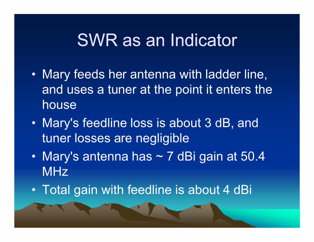
• Mary feeds her antenna with ladder line, and uses a tuner at the point it enters the house
• Mary's feedline loss is about 3 dB, and tuner losses are negligible
• Mary's antenna has ~ 7 dBi gain at 50.4 MHz
• Total gain with feedline is about 4 dBi

SWR as an IndicatorSWR as an Indicator
• Antenna pattern with and without feedline losses

SWR as an IndicatorSWR as an Indicator
• Very High SWR does notindicate your antenna won't
work well!
• Total power into the antenna = 9.1 Watts
• Difference from Joe's Antenna ~ 25 dB

Questions?Questions?
If you have any questions while reviewing the
material or the CD, please e-mail me at:
or
See: www.k9vic.info