General Information -...
166
Transcript of General Information -...

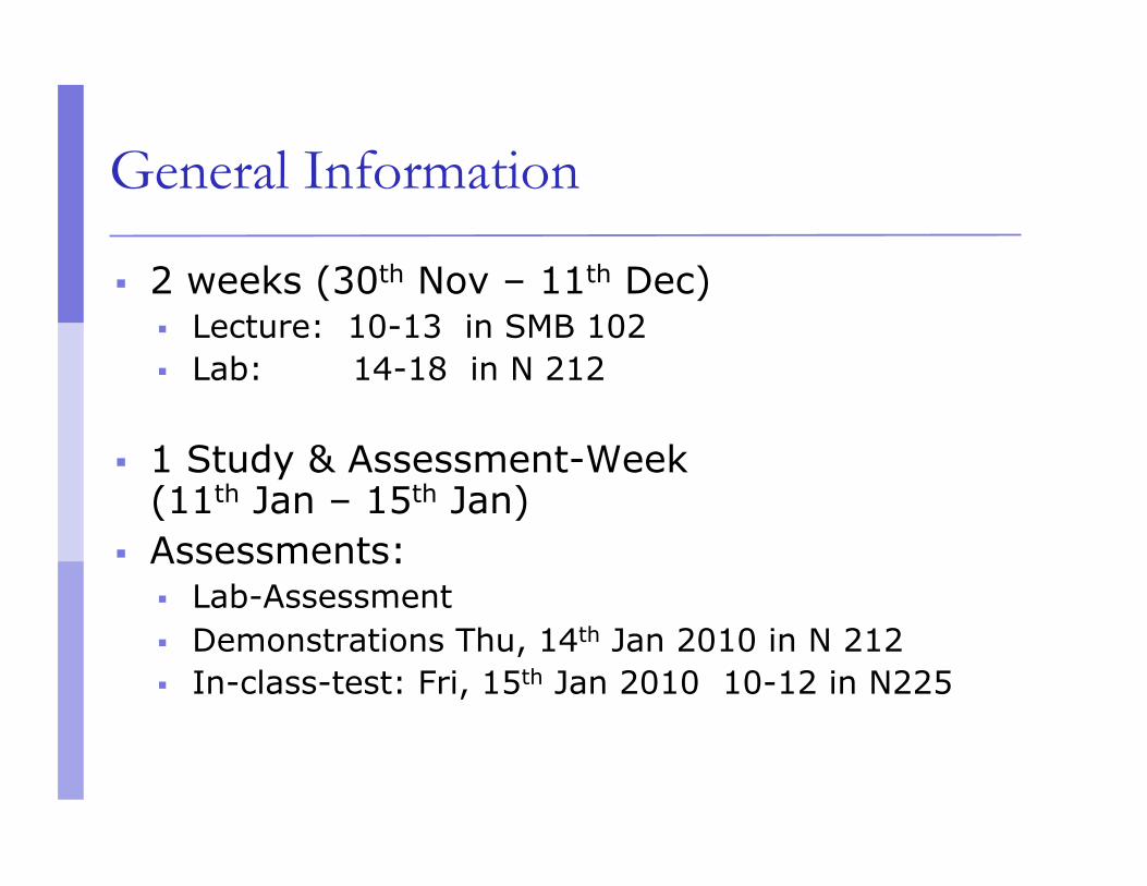
General Information
2 weeks (30th Nov – 11th Dec) Lecture: 10-13 in SMB 102 Lab: 14-18 in N 212
1 Study & Assessment-Week (11th Jan – 15th Jan)
Assessments: Lab-Assessment Demonstrations Thu, 14th Jan 2010 in N 212 In-class-test: Fri, 15th Jan 2010 10-12 in N225
Module Objectives
Basis foundations about how the Internet works.
Hands-on-experience with real Internet hardware in a Lab

IP and Networking Basics

Internet History
1961: Kleinrock - queueing theory shows effectiveness of packet-switching 1964: Baran - packet-switching in military nets 1967: ARPAnet conceived by Advanced Research Projects Agency 1969: first ARPAnet node operational
1972: ARPAnet demonstrated publicly NCP (Network Control Protocol) first host-host protocol first e-mail program ARPAnet has 15 nodes
1961-1972: Early packet-switching principles
Internet History
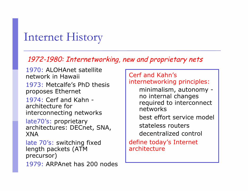
1970: ALOHAnet satellite network in Hawaii 1973: Metcalfe’s PhD thesis proposes Ethernet 1974: Cerf and Kahn - architecture for interconnecting networks late70’s: proprietary architectures: DECnet, SNA, XNA late 70’s: switching fixed length packets (ATM precursor) 1979: ARPAnet has 200 nodes
Cerf and Kahn’s internetworking principles:
minimalism, autonomy - no internal changes required to interconnect networks best effort service model stateless routers decentralized control
define today’s Internet architecture
1972-1980: Internetworking, new and proprietary nets
Internet History
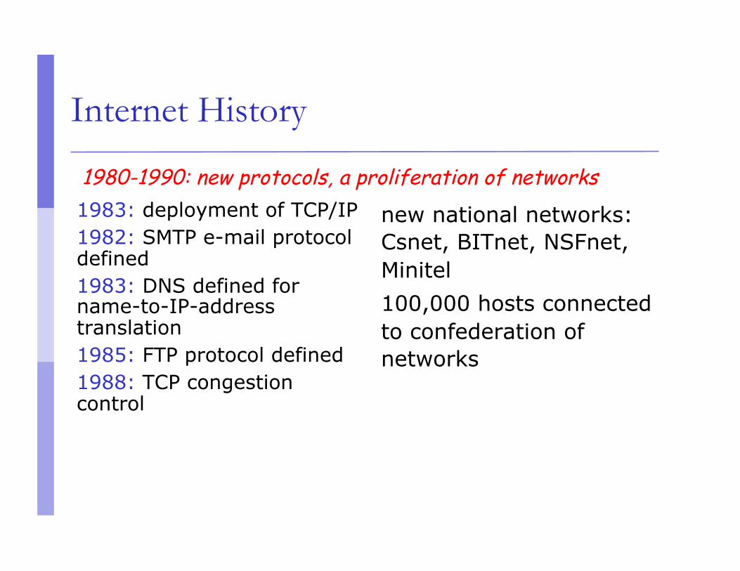
1983: deployment of TCP/IP 1982: SMTP e-mail protocol defined 1983: DNS defined for name-to-IP-address translation 1985: FTP protocol defined 1988: TCP congestion control
new national networks: Csnet, BITnet, NSFnet, Minitel 100,000 hosts connected to confederation of networks
1980-1990: new protocols, a proliferation of networks

Internet History
Early 1990’s: ARPAnet decommissioned 1991: NSF lifts restrictions on commercial use of NSFnet (decommissioned, 1995) early 1990s: Web
hypertext [Bush 1945, Nelson 1960’s] HTML, HTTP: Berners-Lee 1994: Mosaic, later Netscape late 1990’s: commercialization of the Web
Late 1990’s – 2000’s: more killer apps: instant messaging, peer2peer file sharing (e.g., Naptser) network security to forefront est. 50 million host, 100 million+ users backbone links running at Gbps now: 10-40 Gbps youtube, social networking
1990, 2000’s: commercialization, the Web, new apps

The (capital “I”) Internet
The world-wide network of TCP/IP networks Different people or organisations own different
parts Different parts use different technologies Interconnections between the parts Interconnections require agreements
sale/purchase of service contracts “peering” agreements
No central control or management

A small internetwork or (small “i”) “internet”

The principle of “Internetworking”
We have lots of little networks Many different owners/operators Many different types
Ethernet, dedicated leased lines, dialup, optical, broadband, wireless, ...
Each type has its
own idea of low level addressing and protocols We want to connect them all together and provide a unified view of the whole lot (treat the
collec

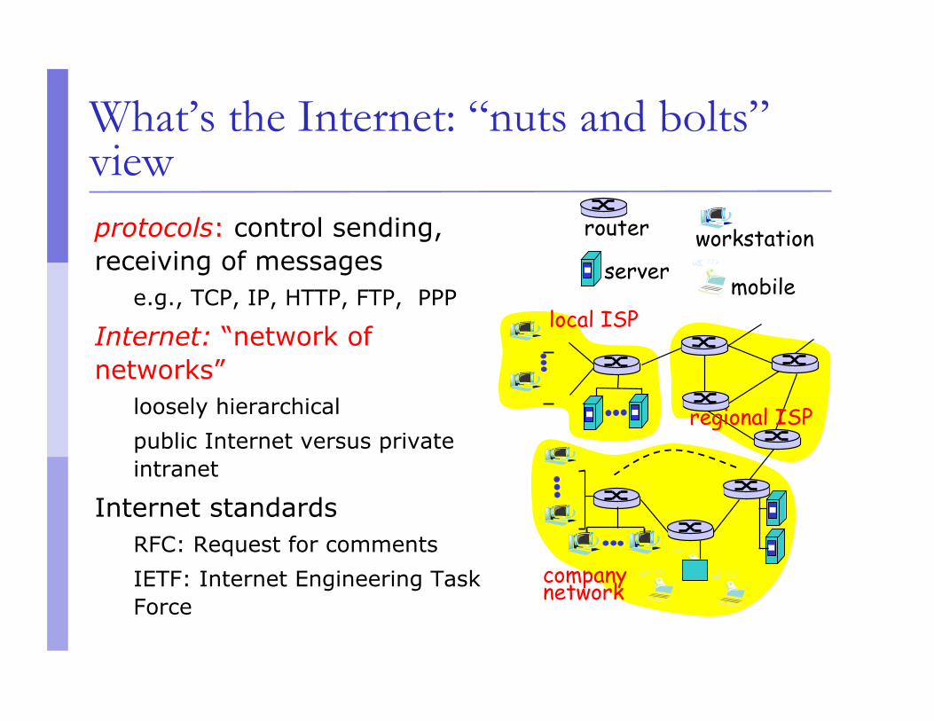
What’s the Internet: “nuts and bolts” view millions of connected computing devices: hosts, end-systems
PC’s workstations, servers PDA’s phones, toasters
running network apps communication links
fiber, copper, radio, satellite
routers: forward packets (chunks) of data through network
local ISP
company network
regional ISP
router workstation server
mobile
What’s the Internet: “nuts and bolts” view
local ISP
company network
regional ISP
router workstation server
mobile
protocols: control sending, receiving of messages
e.g., TCP, IP, HTTP, FTP, PPP
Internet: “network of networks”
loosely hierarchical public Internet versus private intranet
Internet standards RFC: Request for comments IETF: Internet Engineering Task Force

What’s the Internet: a service view
local ISP
company network
regional ISP
router workstation server
mobile
communication infrastructure enables distributed applications:
WWW, email, games, e-commerce, database, e-voting, more?
communication services provided:
connectionless connection-oriented

Connectionless Paradigm
There is no “connection” in IP Packets can be delivered out-of-order Each packet can take a different path to the
destination No error detection or correction in payload No congestion control (beyond “drop”)
TCP mitigates these for connection-oriented applications error correction is by retransmission
OSI Stack & TCP/IP Architecture

Principles of the Internet
Edge vs. core (end-systems vs. routers) Dumb network Intelligence at the end-systems
Different communication paradigms Connection oriented vs. connection less Packet vs. circuit switching
Layered System Network of collaborating networks

The network edge
end systems (hosts): run application programs e.g., WWW, email at “edge of network”
client/server model: client host requests, receives service from server e.g., WWW client (browser)/ server; email client/server
peer-peer model: host interaction symmetric e.g.: teleconferencing

Network edge: connection-oriented service Goal: data transfer between end sys. handshaking: setup (prepare for) data transfer ahead of time
Hello, hello back human protocol set up “state” in two communicating hosts
TCP - Transmission Control Protocol
Internet’s connection-oriented service
TCP service [RFC 793] reliable, in-order byte-stream data transfer
loss: acknowledgements and retransmissions
flow control: sender won’t overwhelm receiver
congestion control: senders “slow down sending rate” when network congested

Network edge: connectionless service
Goal: data transfer between end systems
UDP - User Datagram Protocol [RFC 768]: Internet’s connectionless service unreliable data transfer no flow control no congestion control
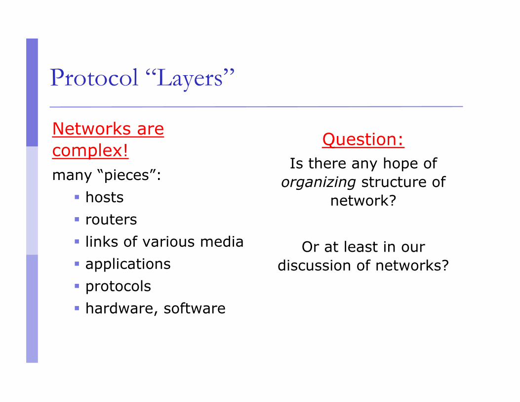
Protocol “Layers”
Networks are complex! many “pieces”:
hosts routers links of various media applications protocols hardware, software
Question: Is there any hope of
organizing structure of network?
Or at least in our discussion of networks?

The unifying effect of the network layer
Define a protocol that works in the same way with any underlying network
Call it the network layer (e.g. IP) IP routers operate at the network layer IP over anything Anything over IP

Why layering?
Dealing with complex systems: explicit structure allows identification,
relationship of complex system’s pieces layered reference model for discussion
modularization eases maintenance, updating of system change of implementation of layer’s service
transparent to rest of system e.g., change in gate procedure does not affect rest
of system
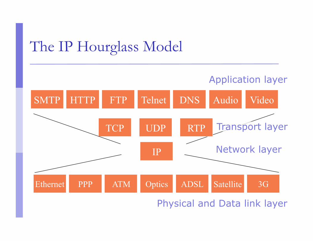
The IP Hourglass Model
Network layer
PPP ATM Optics ADSL Satellite 3G Ethernet
IP
UDP TCP
HTTP FTP Telnet DNS SMTP Audio Video
RTP
Physical and Data link layer
Application layer
Transport layer
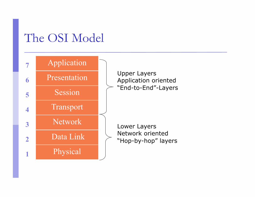
The OSI Model
Upper Layers Application oriented “End-to-End”-Layers
Lower Layers Network oriented “Hop-by-hop” layers
1
3
2
4
5
6
7 Application
Presentation
Session
Transport
Network
Data Link
Physical
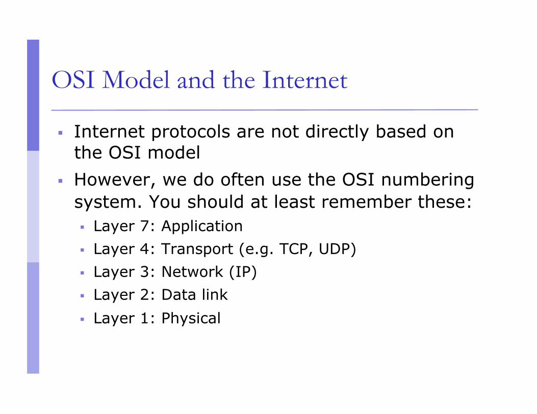
OSI Model and the Internet
Internet protocols are not directly based on the OSI model
However, we do often use the OSI numbering system. You should at least remember these: Layer 7: Application Layer 4: Transport (e.g. TCP, UDP) Layer 3: Network (IP) Layer 2: Data link Layer 1: Physical

Layer Interaction: TCP/IP Model
Host Router Host
Application
TCP or UDP
IP
Link
Physical
IP
Link Link
IP
Link Link
Application
TCP or UDP
IP
Link
Physical Physical
Hop by hop
End to end
Router
End-to-end layers
Upper layers are “end-to-end” Applications at the two ends behave as if they
can talk directly to each other They do not concern themselves with the
details of what happens in between

Hop-by-hop layers
At the lower layers, devices share access to the same physical medium
Devices communicate directly with each other
The network layer (IP) has some knowledge of how many small networks are interconnected to make a large internet
Information moves one hop at a time, getting closer to the destination at each hop

Layer Interaction: TCP/IP Model
Host Router Host
Application
TCP or UDP
IP
Link
Physical
IP
Link Link
IP
Link Link
Application
TCP or UDP
IP
Link
Physical Physical
Router

Layer Interaction: The Application Layer
Host Router Host
Application
TCP or UDP
IP
Link
Physical
IP
Link Link
IP
Link Link
Application
TCP or UDP
IP
Link
Physical Physical
Router
Applications behave as if they can talk to each other, but in reality the application at each side talks to the
TCP or UDP service below it.
The application layer doesn't care about what happens at the lower layers, provided the transport layer
carries the application's data safely from end to end.

Layer Interaction: The Transport Layer
Host Router Host
Application
TCP or UDP
IP
Link
Physical
IP
Link Link
IP
Link Link
Application
TCP or UDP
IP
Link
Physical Physical
Router
The transport layer instances at the two ends act as if they are talking to each other, but in reality they are each talking to the IP layer below it. The transport
layer doesn't care about what the application layer is doing above it.
The transport layer doesn't care what happens in the IP layer or below, as long as the IP layer can move
datagrams from one side to the other.
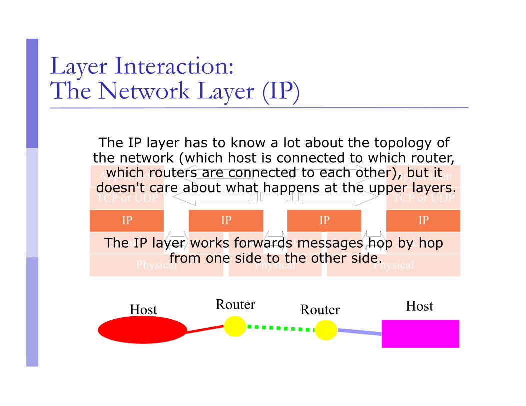
Layer Interaction: The Network Layer (IP)
Host Host
Application
TCP or UDP
IP
Link
Physical
IP
Link Link
IP
Link Link
Application
TCP or UDP
IP
Link
Physical Physical
Router
The IP layer works forwards messages hop by hop from one side to the other side.
The IP layer has to know a lot about the topology of the network (which host is connected to which router,
which routers are connected to each other), but it doesn't care about what happens at the upper layers.
Router

Layer Interaction: Link and Physical Layers
Host Router Host
Application
TCP or UDP
IP
Link
Physical
IP
Link Link
IP
Link Link
Application
TCP or UDP
IP
Link
Physical Physical
Router
The link layer doesn't care what happens above it, but it is very closely tied to the physical layer below it.
All links are independent of each other, and have no way of communicating with each other.

Layering: physical communication
application transport network
link physical
application transport network
link physical application
transport network
link physical
application transport network
link physical
network link
physical
data
data

Frame, Datagram, Segment, Packet
Different names for packets at different layers Ethernet (link layer) frame IP (network layer) datagram TCP (transport layer) segment
Terminology is not strictly followed we often just use the term “packet” at any layer
Encapsulation & Decapsulation
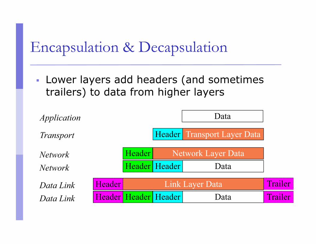
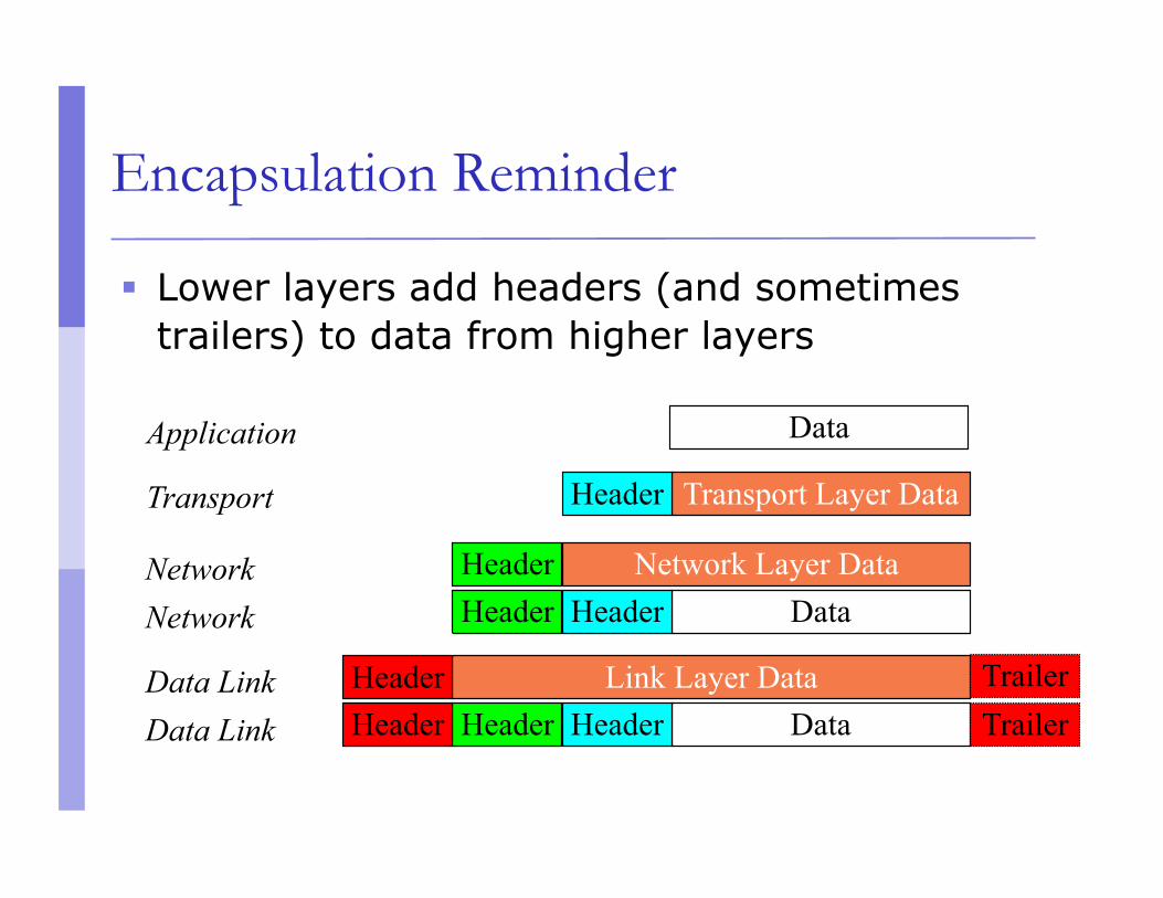
Lower layers add headers (and sometimes trailers) to data from higher layers
Application
Transport
Network
Data Link Data Link
Network
Data
Transport Layer Data Header
Network Layer Data Header Data Header Header
Link Layer Data Data Header Header
Header Header
Trailer Trailer

Layer 2 - Ethernet frame
Destination and source are 48-bit MAC addresses (e.g., 00:26:4a:18:f6:aa)
Type 0x0800 means that the “data” portion of the Ethernet frame contains an IPv4 datagram. Type 0x0806 for ARP. Type 0x86DD for IPv6.
“Data” part of layer 2 frame contains a layer 3 datagram.
Preamble Dest 6 bytes
Source 6 bytes
Data 46 to 1500
bytes
CRC 4 bytes
Type 2 bytes

IHL Differentiated Services Total Length Version Fragment Offset Identification Flags
Time to Live Protocol Header Checksum Source Address (32-bit IPv4 address)
Destination Address (32-bit IPv4 address)
Data (contains layer 4 segment) Padding Options
Layer 3 - IPv4 datagram
Protocol = 6 means data portion contains a TCP segment. Protocol = 17 means UDP.
Version = 4 If no options, IHL = 5 Source and Destination are 32-bit IPv4 addresses

Layer 4 - TCP segment
Source and Destination are 16-bit TCP port numbers (IP addresses are implied by the IP header)
If no options, Data Offset = 5 (which means 20 octets)
Source Port Destination Port Sequence Number
Acknowledgement Number Data Offset
Window Reserved ACK
URG
EOL
RST
SYN
FIN
Checksum Urgent Pointer
Data (contains application data) Padding Options

IP Addressing

Purpose of an IPv4 address
Unique Identification of: Source
So the recipient knows where the message is from Sometimes used for security or policy-based filtering of
data
Destination So the networks know where to send the data
Network Independent Format IP over anything

Purpose of an IP Address
Identifies a machine’s connection to a network Physically moving a machine from
one network to another requires changing the IP address
Unique; assigned in a hierarchical fashion IANA (Internet Assigned Number Authority) IANA to RIRs (AfriNIC, ARIN, RIPE, APNIC, LACNIC) RIR to ISPs and large organisations ISP or company IT department to end users
IPv4 uses unique 32-bit addresses IPv6 used similar concepts but 128-bit addresses
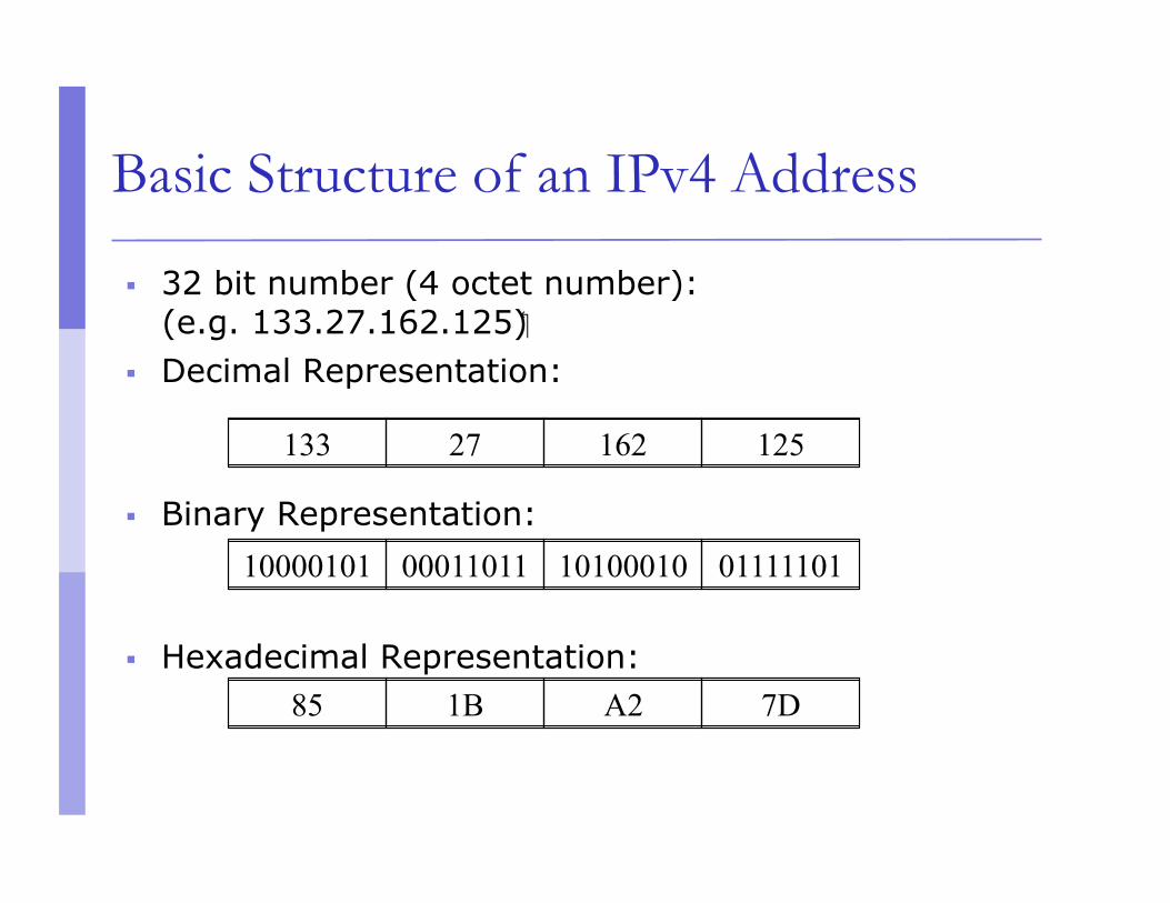
133 27 162 125
10000101 00011011 10100010 01111101
85 1B A2 7D
Basic Structure of an IPv4 Address
32 bit number (4 octet number): (e.g. 133.27.162.125)
Decimal Representation:
Binary Representation:
Hexadecimal Representation:
Addressing in Internetworks
The problem we have More than one physical network Different Locations Larger number of hosts Need a way of numbering them all
We use a structured numbering system Hosts that are connected to the same physical
network have “similar” IP addresses Often more then one level of structure; e.g.
physical networks in the same organisation use “similar” IP addresses
Network part and Host part
Remember IPv4 address is 32 bits Divide it into a “network part” and “host part”
“network part” of the address identifies which network in the internetwork (e.g. the Internet)
“host part” identifies host on that network Hosts or routers connected to the same link-layer network will have IP
addresses
with the same network part, but different host part. Host part contains enough bits to address
all

Dividing an address
Hierarchical Division in IP Address: Network Part (or Prefix) – high order bits (left)
describes which physical network
Host Part – low order bits (right) describes which host on that network
Boundary can be anywhere choose the boundary according to number of hosts very often NOT a multiple of 8 bits
Network Part Host Part

Network Masks
“Network Masks” help define which bits are used to describe the Network Part and which for the Host Part
Different Representations: decimal dot notation: 255.255.224.0 binary: 11111111 11111111 11100000 00000000 hexadecimal: 0xFFFFE000 number of network bits: /19
count the 1's in the binary representation
Above examples all mean the same: 19 bits for the Network Part and 13 bits for the Host Part

Example Prefixes
137.158.128.0/17 (netmask 255.255.128.0)
198.134.0.0/16 (netmask 255.255.0.0)
205.37.193.128/26 (netmask 255.255.255.192)
1000 1001 1001 1110 1 000 0000 0000 0000 1111 1111 1111 1111 1 000 0000 0000 0000
1100 0110 1000 0110 0000 0000 0000 0000 1111 1111 1111 1111 0000 0000 0000 0000
1100 1101 0010 0101 1100 0001 10 00 0000 1111 1111 1111 1111 1111 1111 11 00 0000
Special Addresses
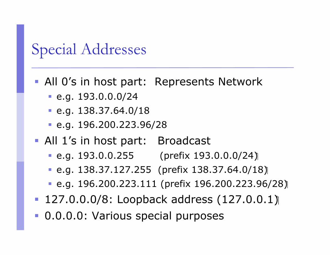
All 0’s in host part: Represents Network e.g. 193.0.0.0/24 e.g. 138.37.64.0/18 e.g. 196.200.223.96/28
All 1’s in host part: Broadcast e.g. 193.0.0.255 (prefix 193.0.0.0/24) e.g. 138.37.127.255 (prefix 138.37.64.0/18) e.g. 196.200.223.111 (prefix 196.200.223.96/28)
127.0.0.0/8: Loopback address (127.0.0.1) 0.0.0.0: Various special purposes

Exercise
Verify that the previous examples are all broadcast addresses: 193.0.0.255 (prefix 193.0.0.0/24) 138.37.127.255 (prefix 138.37.64.0/18) 196.200.223.111 (prefix 196.200.223.96/28)
Do this by finding the boundary between network part and host part, and checking that the
host part (if written in binary) contains all 1's.
Maximum number of hosts per network
The number of bits in the host part determines the maximum number of hosts
The all-zeros and all-ones addresses are reserved, can't be used for actual hosts
E.g. a subnet mask of 255.255.255.0 or /24 means 24 network bits, 8 host bits (24+8=32) 28 minus 2 = 254 possible hosts
Similarly a subnet mask of 255.255.255.224

More Address Exercises
Assuming there are 9 routers on the classroom backbone network: what is the minimum number of host bits needed
to address each router with a unique IP address? with that many host bits, how many network bits? what is the corresponding prefix length in “slash”
notation? what is the corresponding netmask (in decimal)? with that netmask, what is the maximum number
of hosts?

More levels of address hierarchy
Extend the concept of “network part” and “host part”: arbitrary number of levels of hierarchy blocks don’t all need to be the same size but each block size must be a power of 2
Very large blocks allocated to RIRs (e.g. /8) Divided into smaller blocks for ISPs (e.g. /17)
Divided into smaller blocks for businesses (e.g. /22) Divided into smaller blocks for local networks (e.g. /26)
Each host gets a host address
What if addresses overlap??

Ancient History: Classful Addressing
Nowadays, we always explicitly say where the boundary between network and host part is using slash notation or netmask notation
Old systems used restrictive rules (obsolete) Called “Class A”, “Class B”, “Class C” networks Boundary
between
network part and host part was implied by the class
Nowadays (since 1994), no restriction
Ancient History: Sizes of classful networks Different classes were used to represent
different sizes of network (small, medium, large)
Class A networks (large): 8 bits network part, 24 bits host part
Class B networks (medium): 16 bits network part, 16 bits host part
Class C networks (small): 24 bits network part, 8 bits host part

Ancient History: What class is my address? Just look at the address to tell what class it is.
Class A: 0.0.0.0 to 127.255.255.255 binary 0nnnnnnnhhhhhhhhhhhhhhhhhhhhhhhh
Class B: 128.0.0.0 to 191.255.255.255 binary 10nnnnnnnnnnnnnnhhhhhhhhhhhhhhhh
Class C: 192.0.0.0 to 223.255.255.255 binary 110nnnnnnnnnnnnnnnnnnnnnhhhhhhhh
Class D: (multicast) 224.0.0.0 to 239.255.255.255 binary 1110xxxxxxxxxxxxxxxxxxxxxxxxxxxx
Class E: (reserved) 240.0.0.0 to 255.255.255.255

Ancient History: Implied netmasks
A classful network had a “natural” or “implied” prefix length or netmask: Class A: prefix length /8 (netmask 255.0.0.0) Class B: prefix length /16 (netmask 255.255.0.0) Class C: prefix length /24 (netmask 255.255.255.0)
Modern (classless) routing systems have explicit prefix lengths or netmasks You can't just look at an IP address to tell what the prefix length or netmask should be.
Protocols a

Classless addressing
Class A, Class B, Class C terminology and restrictions are now of historical interest only Obsolete in 1994
Internet routing and address management today is classless
CIDR = Classless Inter-Domain Routing routing does not assume that class A, B, C implies
prefix length /8, /16, /24
VLSM = Variable-Length Subnet Masks routing does not assume that all subnets are the
same size

Classless addressing example
An ISP gets a large block of addresses e.g., a /16 prefix, or 65536 separate addresses
Allocate smaller blocks to customers e.g., a /22 prefix (1024 addresses) to one customer,
and a /28 prefix (16 addresses) to another customer (and some space left over for other customers)
An organisation that gets a /22 prefix from their ISP divides it into smaller blocks e.g. a /26 prefix (64 addresses) for one department,
and a /27 prefix (32 addresses) for another department (and some space left over for other internal networks)

Classless addressing exercise
Consider the address block 133.27.162.0/23 Allocate 5 separate /29 blocks, one /27 block, and
one /25 block What are the IP addresses of each block allocated
above? in prefix length notation netmasks in decimal IP address ranges
What blocks are still available (not yet allocated)? How big is the largest available block?

IPv6
IP version 6
IPv6 designed as successor to IPv4 Expanded address space
Address length quadrupled to 16 bytes (128 bits)
Header Format Simplification Fixed length, optional headers are daisy-chained
No checksum at the IP network layer 64 bits aligned fields in the header Authentication and Privacy Capabilities
IPsec is mandated
No more broadcast

IPv4 and IPv6 Header Comparison
IPv4 Header IPv6 Header
Field’s name kept from IPv4 to IPv6
Fields not kept in IPv6 Name and position changed in IPv6 New field in IPv6
Lege
nd
Next Header Hop Limit
Flow Label Traffic Class
Destination Address
Source Address
Payload Length
Version
Fragment Offset Flags
Total Length Type of Service IHL
Padding Options
Destination Address
Source Address
Header Checksum Protocol Time to Live
Identification
Version

Larger Address Space
IPv4 32 bits = 4,294,967,296 possible addressable devices
IPv6 128 bits: 4 times the size in bits = 3.4 x 1038 possible addressable devices = 340,282,366,920,938,463,463,374,607,431,768,211,456 ∼ 5 x 1028 addresses per person on the planet
IPv4 = 32 bits
IPv6 = 128 bits
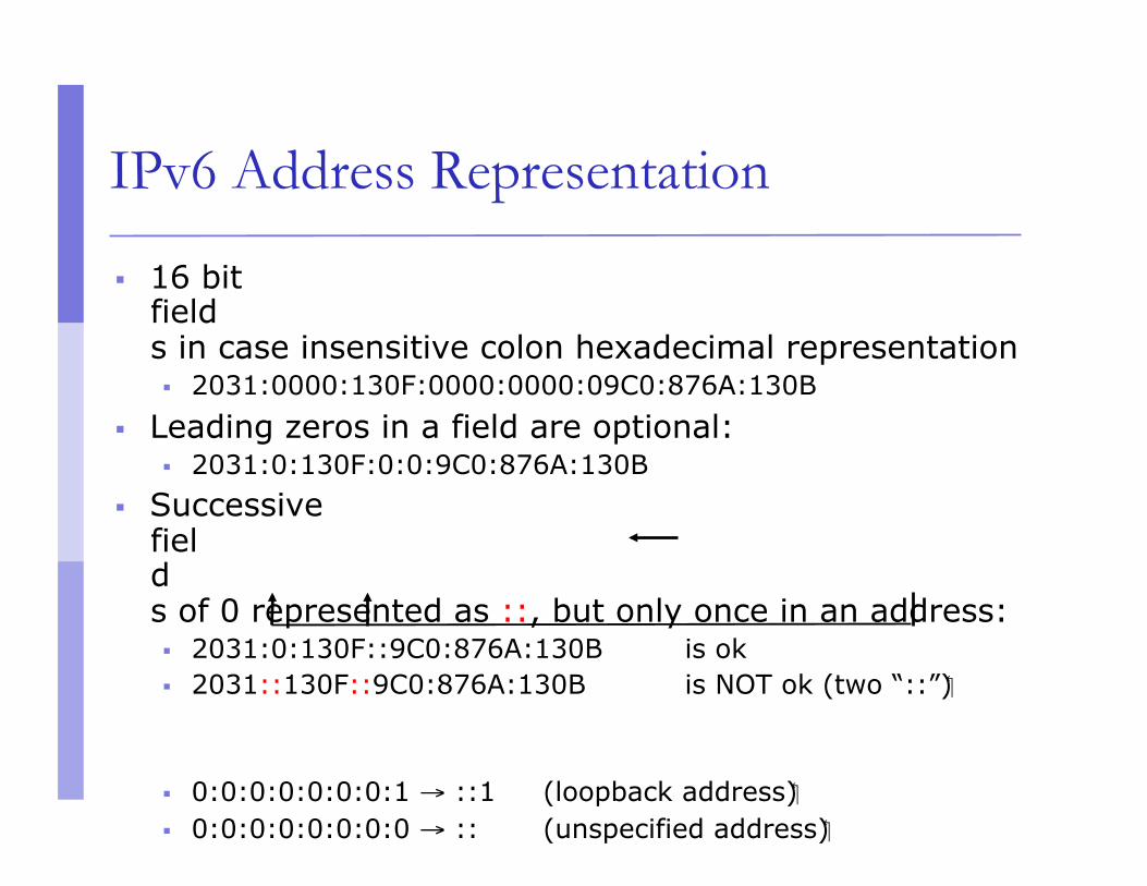
IPv6 Address Representation
16 bit fields in case insensitive colon hexadecimal representation 2031:0000:130F:0000:0000:09C0:876A:130B
Leading zeros in a field are optional: 2031:0:130F:0:0:9C0:876A:130B
Successive fields of 0 represented as ::, but only once in an address: 2031:0:130F::9C0:876A:130B is ok 2031::130F::9C0:876A:130B is NOT ok (two “::”)
0:0:0:0:0:0:0:1 → ::1 (loopback address) 0:0:0:0:0:0:0:0 → :: (unspecified address)
IPv6 Address Representation
In a URL, it is enclosed in brackets (RFC3986) http://[2001:4860:b006::67]:80/index.html Cumbersome for users Mostly for diagnostic purposes Use fully qualified domain names (FQDN) instead of this
Prefix Representation Representation of prefix is same as for IPv4 CIDR
Address and then prefix length, with slash separator
IPv4 address: 198.10.0.0/16
IPv6 address: 2001:db8:12::/40

IPv6 Addressing
::/128 0000…0000 Unspecified
::1/128 0000…0001 Loopback
FF00::/8 1111 1111 ... Multicast Address
FC00::/7 1111 1100 ... 1111 1101 ...
Unique Local Unicast Address
FE80::/10 1111 1110 10... Link Local Unicast Address
2000::/3 001 ... Global Unicast Address
Hex Binary Type

Interface ID Global Routing Prefix Subnet-id
001
64 bits 48 bits 16 bits
Provider Site Host
IPv6 Global Unicast Addresses
IPv6 Global Unicast addresses are: Addresses for generic use of IPv6 Hierarchical structure intended to simplify
aggregation
2000 0db8
ISP prefix Site prefix LAN prefix
/32 /48 /64
Registry
/12
Interface ID
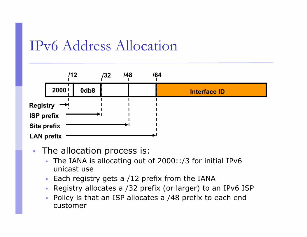
IPv6 Address Allocation
The allocation process is: The IANA is allocating out of 2000::/3 for initial IPv6
unicast use Each registry gets a /12 prefix from the IANA Registry allocates a /32 prefix (or larger) to an IPv6 ISP Policy is that an ISP allocates a /48 prefix to each end
customer

IPv6 Addressing Scope
64 bits reserved for the interface ID Possibility of 264 hosts on one network LAN Arrangement to
accommodate MAC addresses within the IPv6 address
16 bits reserved for the end site Possibility of 216 networks at each end-site 65536 subnets equivalent
to a /12 in IPv4 (assuming 16 hosts per IPv4 subnet)

IPv6 Addressing Scope
16 bits reserved for the service provider Possibility of 216 end-sites per service provider 65536 possible customers: equivalent to each service provider receiving a /8
in IPv4 (assuming a /24 address block per customer)
32 bits reserved for service providers Possibility of 232 service providers i.e. 4 billion discrete service provider networks
Although some service providers already are justifying more than a /32
Equivalent to the size of the entire IPv4 address space
IPv6 Benefits: Autoconfiguration
Every link uses fe80::/64 for link-local stuff Hosts in isolated networks automatically
communicate
Router can announce global addresses Router Advertisement (RA) ICMP packets e.g., 2001:608:4:0::/64
Clients will use all available /64 prefixes Compute the host part from their MAC address EUI-64: Algorithm for computing 64-bit host part
from 48-bit (Ethernet) MAC address
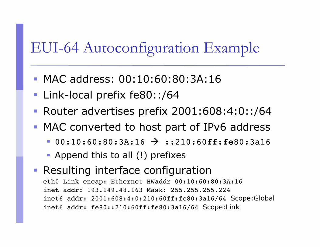
EUI-64 Autoconfiguration Example
MAC address: 00:10:60:80:3A:16 Link-local prefix fe80::/64 Router advertises prefix 2001:608:4:0::/64 MAC converted to host part of IPv6 address
00:10:60:80:3A:16 ::210:60ff:fe80:3a16
Append this to all (!) prefixes
Resulting interface configuration eth0 Link encap: Ethernet HWaddr 00:10:60:80:3A:16inet addr: 193.149.48.163 Mask: 255.255.255.224inet6 addr: 2001:608:4:0:210:60ff:fe80:3a16/64 Scope:Global inet6 addr: fe80::210:60ff:fe80:3a16/64 Scope:Link

Migration towards IPv6
Problems v4 host wanting to talk to v6 host v6 networks that are only connected by v4
infrastructure
Migration techniques: Dual-stacked hosts/router (v4+v6 IP stack on
same machine) Dual-stacked proxies / application-level gateways Tunnelling
Manually configured tunnels Automatic tunnelling (6to4, ISATAP, Teredo) Tunnels configured by tunnel broker
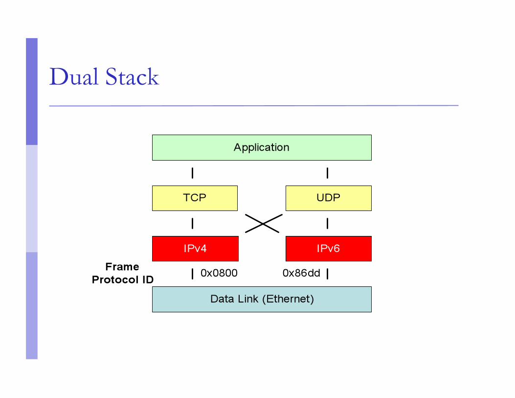
Dual Stack
Summary
Vast address space Hexadecimal addressing Distinct addressing hierarchy between ISPs,
end-sites, and LANs ISPs have /32s End-sites have /48s LANs have /64s
Other IPv6 features discussed later

Large Network Issues & Routers
The need for Packet Forwarding
Many small networks can be interconnected to make a larger internetwork
A device on one network cannot send a packet directly to a device on another network
The packet has to be forwarded from one network to another, through intermediate nodes, until it reaches its destination
The intermediate nodes are called “routers”

An IP Router
A device with more than one link-layer interface
Different IP addresses (from different subnets) on different interfaces
Receives packets on one interface, and forwards them (usually out of another interface) to get them one hop closer to their destination
Maintains forwarding tables

IP Router - action for each packet
Packet is received on one interface Checks whether the destination address is the
router itself – if so, pass it to higher layers Decrement TTL (time to live), and discard
packet if it reaches zero Look up the destination IP address in the
forwarding table Destination could be on a directly attached
link, or through another router
Forwarding vs. Routing
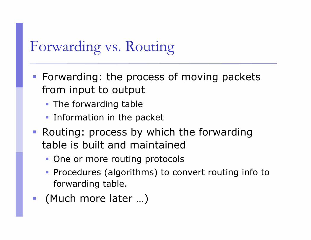
Forwarding: the process of moving packets from input to output The forwarding table Information in the packet
Routing: process by which the forwarding table is built and maintained One or more routing protocols Procedures (algorithms) to convert routing info to
forwarding table.
(Much more later …)

Forwarding is hop by hop
Each router tries to get the packet one hop closer to the destination
Each router makes an independent decision, based on its own forwarding table
Different routers have different forwarding tables and make different decisions If all is well, decisions will be consistent
Routers talk routing protocols to each other, to help update routing and forwarding tables

Hop by Hop Forwarding

Router Functions
Determine optimum routing paths through a network Lowest delay Highest reliability
Move packets through the network Examines destination address in packet Makes a decision on which port to forward the packet through Decision is based on the Routing Table
Interconnected Routers exchange routing tables in order to maintain a clear picture of the network
In a large network, the routing table updates can consume a lot of bandwidth a protocol for route updates is required

Forwarding table structure
We don't list every IP number on the Internet - the table would be huge
Instead, the forwarding table contains prefixes (network numbers) "If the first /n bits matches this entry, send the
datagram that way"
If more than one prefix matches, the longest prefix wins (more specific route)
0.0.0.0/0 is "default route" - matches anything, but only if no other prefix matches

IPv6 Forwarding & Routing
Forwarding / routing table lookup: similar to IPv4 Same basic rule: "most specific wins"
2001:608:b:1::/64 2001:608:b::/48
Default route is 0::0/0 Routing protocols (BGP, ISIS) and routing table
buildup follow same principles as IPv4
p LIR-Alloc NLA SLA Interface-ID 64 Bit 0 3 32 48 64 128

ARP
Encapsulation Reminder
Lower layers add headers (and sometimes trailers) to data from higher layers
Application
Transport
Network
Data Link Data Link
Network
Data
Transport Layer Data Header
Network Layer Data Header Data Header Header
Link Layer Data Data Header Header
Header Header
Trailer Trailer
Ethernet Reminder
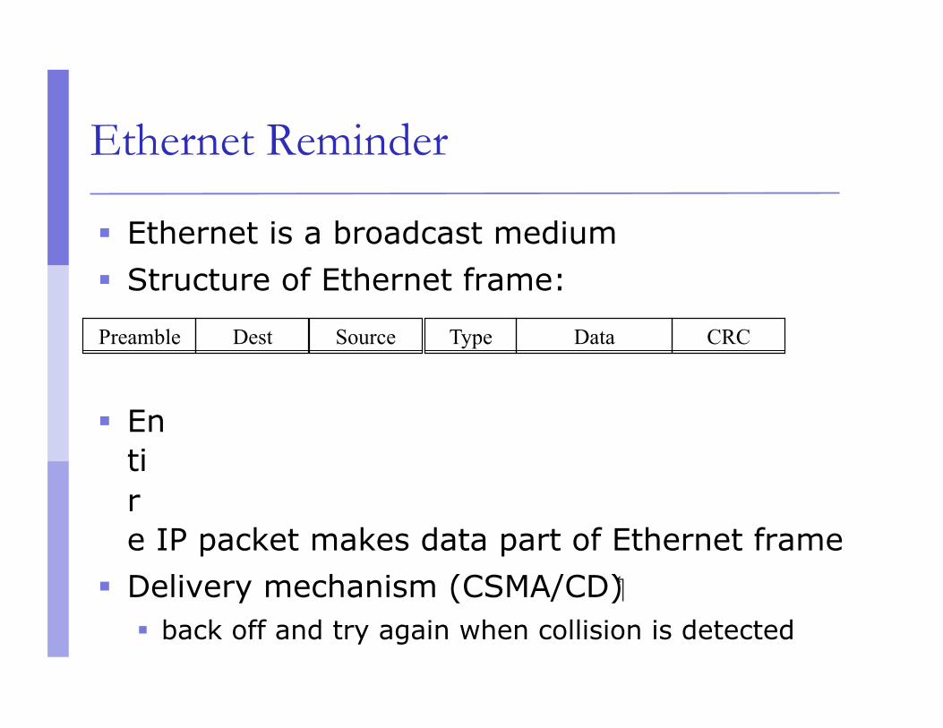
Ethernet is a broadcast medium Structure of Ethernet frame:
Entire IP packet makes data part of Ethernet frame
Delivery mechanism (CSMA/CD) back off and try again when collision is detected
Preamble Dest Source Data CRC Type

Ethernet/IP Address Resolution
Internet Address Unique worldwide (excepting private nets) Independent of Physical Network technology
Ethernet Address Unique worldwide (excepting errors) Ethernet Only
Need to map from higher layer to lower (i.e. IP to Ethernet, using ARP)
Address Resolution Protocol
ARP is only used in IPv4 ND replaces ARP in IPv6
Check ARP cache for matching IP address If not found, broadcast packet with IP address
to every host on Ethernet “Owner” of the IP address responds Response cached in ARP table for future use Old cache entries removed by timeout
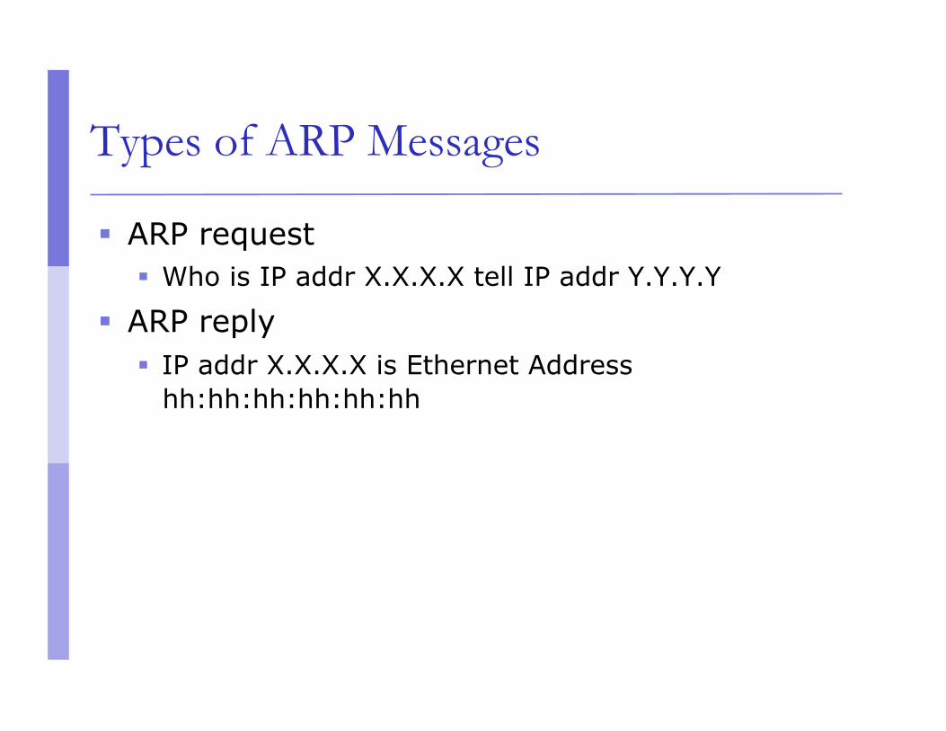
Types of ARP Messages
ARP request Who is IP addr X.X.X.X tell IP addr Y.Y.Y.Y
ARP reply IP addr X.X.X.X is Ethernet Address
hh:hh:hh:hh:hh:hh

ARP Procedure
1. ARP Cache is checked
2. ARP Request is Sent using broadcast
3. ARP Entry is added
4. ARP Reply is sent unicast
5. ARP Entry is added

ARP Table
43 07-01-20-08-73-22 192.168.0.34
120 05-02-20-08-88-33 192.168.0.65
3 08-00-20-08-70-54 192.168.0.2
Age (Sec) Hardware Address IP Address
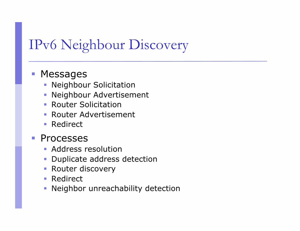
IPv6 Neighbour Discovery
Messages Neighbour Solicitation Neighbour Advertisement Router Solicitation Router Advertisement Redirect
Processes Address resolution Duplicate address detection Router discovery Redirect Neighbor unreachability detection

Cisco Router Configuration
Basics

Router Components
ROM Starts and maintains the router
Bootstrap Stored in ROM microcode – brings router up during initialisation,
boots router and loads the IOS.
POST – Power On Self Test Stored in ROM microcode – checks for basic functionality of router
hardware and determines which interfaces are present
ROM Monitor Stored in ROM microcode – used for manufacturing, testing and
troubleshooting
Mini-IOS a.k.a RXBOOT/boot loader by Cisco – small IOS ROM used to bring
up an interface and load a Cisco IOS into flash memory from a TFTP server; can also perform a few other maintenance operations

Router Components
RAM Holds packet buffers, ARP cache, routing table, software and
data structure that allows the router to function; running-config is stored in RAM, as well as the decompressed IOS in later router models
Flash memory Holds the IOS; is not erased when the router is reloaded; is
an EEPROM [Electrically Erasable Programmable Read-Only Memory] that can be erased and reprogrammed repeatedly through an application of higher than normal electric voltage
NVRAM Non-Volatile RAM - stores router startup-config; is not
erased when router is reloaded
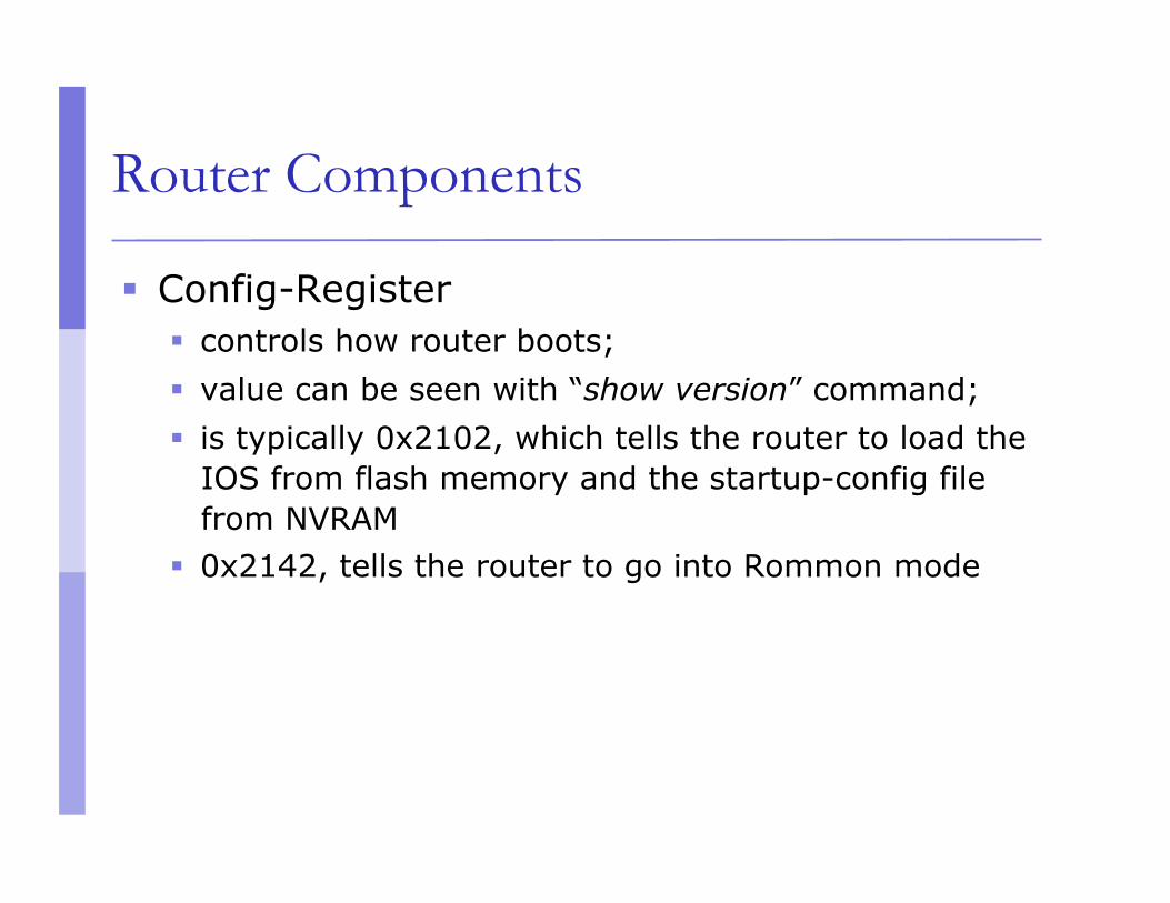
Router Components
Config-Register controls how router boots; value can be seen with “show version” command; is typically 0x2102, which tells the router to load the
IOS from flash memory and the startup-config file from NVRAM
0x2142, tells the router to go into Rommon mode

Purpose of the Config Register
Reasons why you would want to modify the config-register: Force the router into ROM Monitor Mode Select a boot source and default boot filename Enable/Disable the Break function Control broadcast addresses Set console terminal baud rate Load operating software from ROM Enable booting from a TFTP server
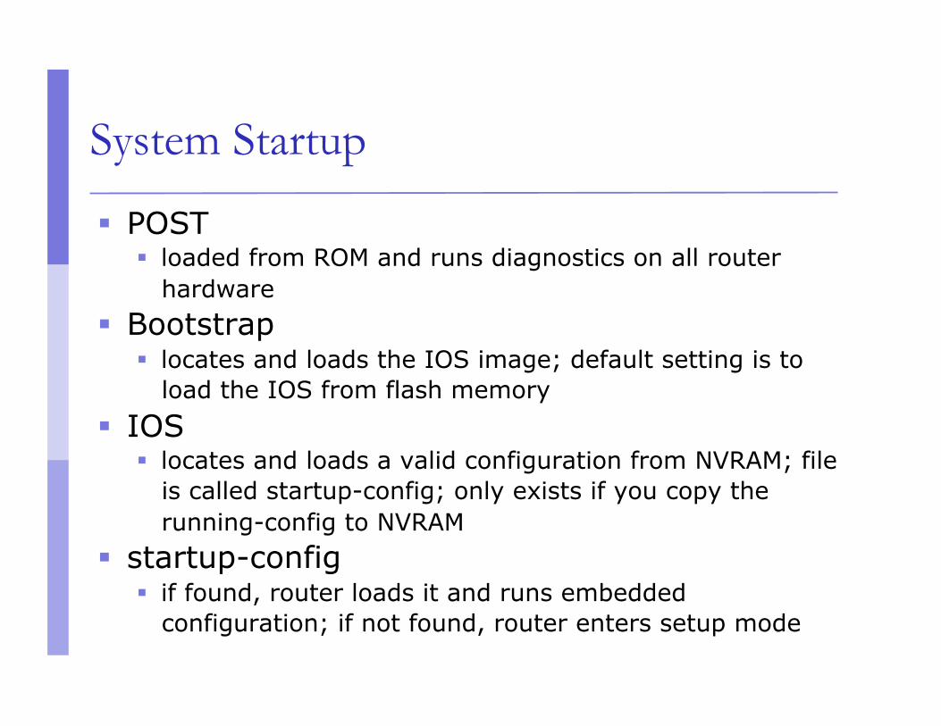
System Startup
POST loaded from ROM and runs diagnostics on all router
hardware Bootstrap
locates and loads the IOS image; default setting is to load the IOS from flash memory
IOS locates and loads a valid configuration from NVRAM; file
is called startup-config; only exists if you copy the running-config to NVRAM
startup-config if found, router loads it and runs embedded
configuration; if not found, router enters setup mode

Overview
Router configuration controls the operation of the router’s: Interface IP address and netmask Routing information (static, dynamic or default) Boot and startup information Security (passwords and authentication)

Where is the Configuration?
Router always has two configurations: Running configuration
In RAM, determines how the router is currently operating
Is modified using the configure command To see it: show running-config
Startup confguration In NVRAM, determines how the router will operate
after next reload Is modified using the copy command To see it: show startup-config

Where is the Configuration?
Can also be stored in more permanent places: External hosts, using TFTP (Trivial File Transfer
Protocol) In flash memory in the router
Copy command is used to move it around copy run start copy run tftp
copy start tftp copy tftp start
copy flash start copy start flash
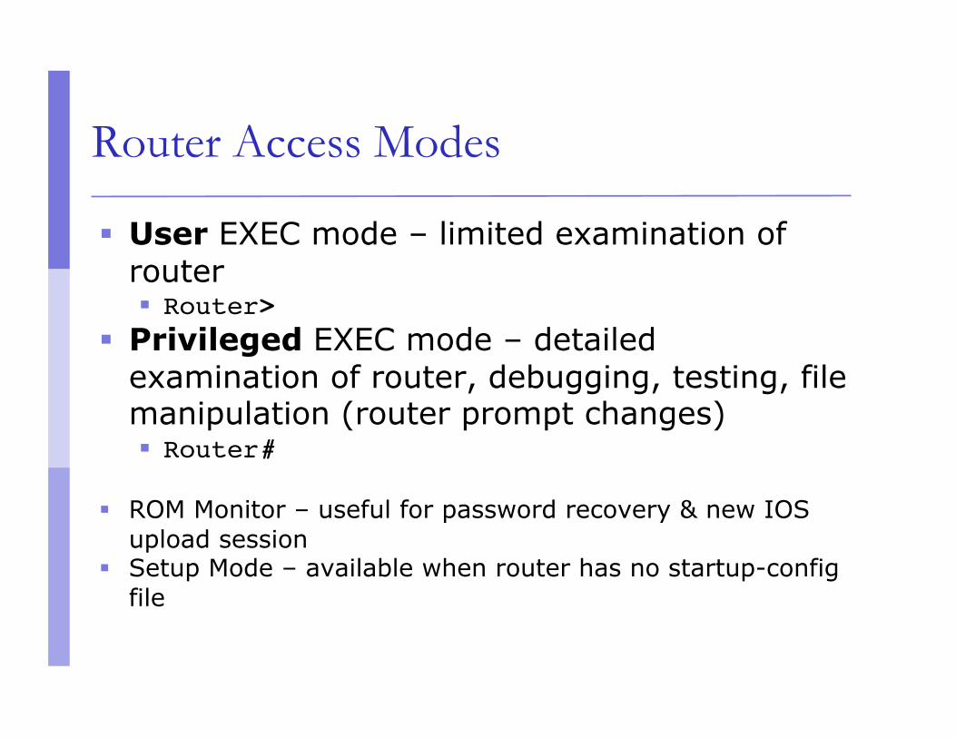
Router Access Modes
User EXEC mode – limited examination of router Router>
Privileged EXEC mode – detailed examination of router, debugging, testing, file manipulation (router prompt changes) Router#
ROM Monitor – useful for password recovery & new IOS upload session
Setup Mode – available when router has no startup-config file

External Configuration Sources
Console Direct PC serial access
Auxiliary port Modem access
Virtual terminals Telnet/SSH access
TFTP Server Copy configuration file into router RAM
Network Management Software e.g., CiscoWorks
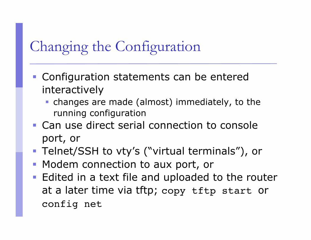
Changing the Configuration
Configuration statements can be entered interactively changes are made (almost) immediately, to the
running configuration Can use direct serial connection to console
port, or Telnet/SSH to vty’s (“virtual terminals”), or Modem connection to aux port, or Edited in a text file and uploaded to the router
at a later time via tftp; copy tftp start or config net
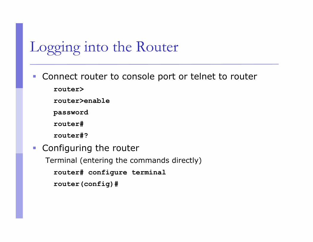
Logging into the Router
Connect router to console port or telnet to router router>
router>enable
password
router#
router#?
Configuring the router Terminal (entering the commands directly) router# configure terminal
router(config)#

New Router Configuration Process
Load configuration parameters into RAM Router#configure terminal
Personalize router identification Router#(config)hostname RouterA
Assign access passwords RouterA#(config)line console 0
RouterA#(config-line)password cisco
RouterA#(config-line)login

New Router Configuration Process
Configure interfaces RouterA#(config)interface fastethernet 0/0
RouterA#(config-if)ip address n.n.n.n m.m.m.m
RouterA#(config-if)no shutdown
Configure routing/routed protocols Save configuration parameters to NVRAM
RouterA#copy running-config startup-config
(or write memory)
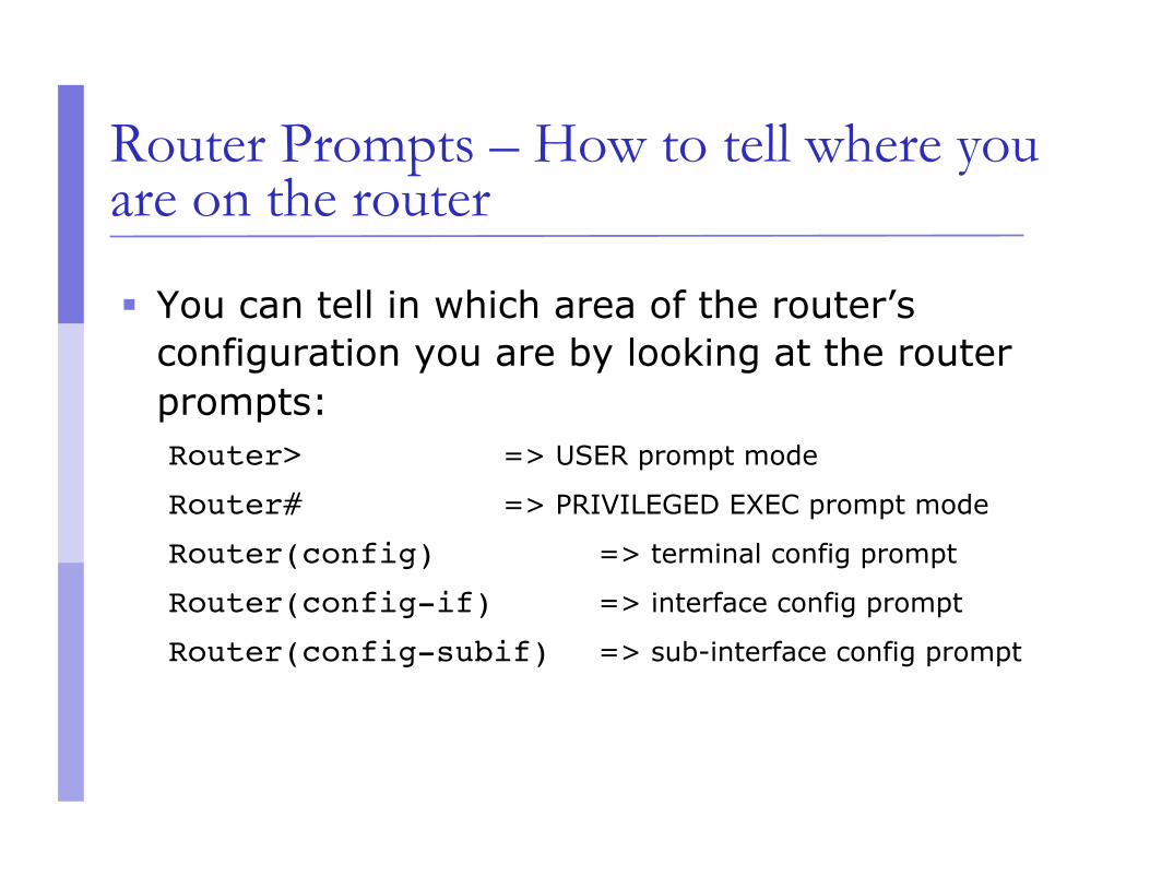
Router Prompts – How to tell where you are on the router
You can tell in which area of the router’s configuration you are by looking at the router prompts: Router> => USER prompt mode
Router# => PRIVILEGED EXEC prompt mode
Router(config) => terminal config prompt
Router(config-if) => interface config prompt
Router(config-subif) => sub-interface config prompt

Router Prompts – How to tell where you are on the router
You can tell in which area of the router’s configuration you are by looking at the router prompts: Router(config-route-map)# => route-map config
Router(config-router)# => router config prompt
Router(config-line)# => line config prompt
rommon 1> => ROM Monitor mode
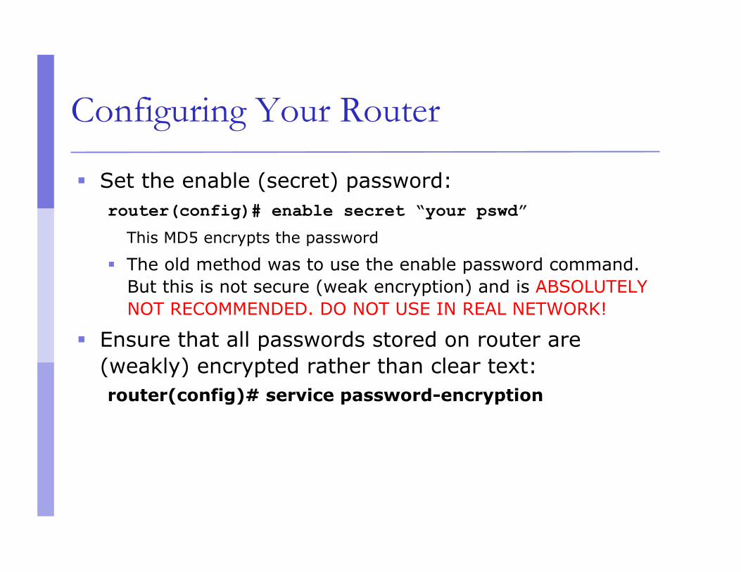
Configuring Your Router
Set the enable (secret) password: router(config)# enable secret “your pswd”
This MD5 encrypts the password
The old method was to use the enable password command. But this is not secure (weak encryption) and is ABSOLUTELY NOT RECOMMENDED. DO NOT USE IN REAL NETWORK!
Ensure that all passwords stored on router are (weakly) encrypted rather than clear text: router(config)# service password-encryption

Configuring Your Router
To configure interface you should go to interface configuration prompt router(config)# interface fastethernet0/0
router(config-if)#
Save your configuration router#copy running-config startup-config

Configuring Your Router
Global: enable secret cop455
Interface: interface fastethernet 0/0 ip address 10.5.2.3 255.255.255.0
Router: router isis net 49.0001.0020.0000.0002.00
Line: line vty 0 4

Global Configuration
Global configuration statements are independent of any particular interface or routing protocol, e.g.:
hostname routerK
enable secret cop455
service password-encryption
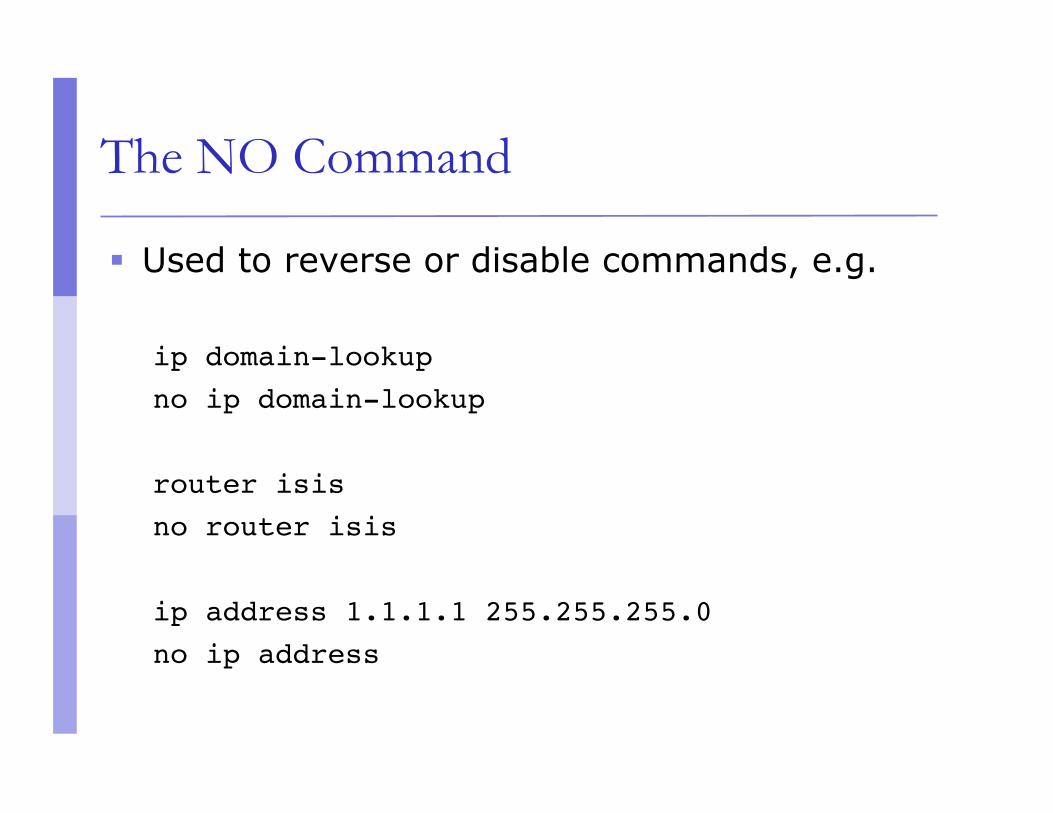
The NO Command
Used to reverse or disable commands, e.g.
ip domain-lookup no ip domain-lookup
router isis no router isis
ip address 1.1.1.1 255.255.255.0 no ip address
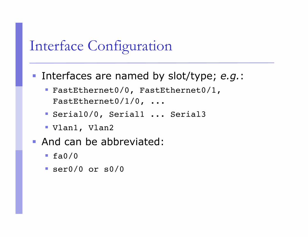
Interface Configuration
Interfaces are named by slot/type; e.g.: FastEthernet0/0, FastEthernet0/1, FastEthernet0/1/0, ...
Serial0/0, Serial1 ... Serial3 Vlan1, Vlan2
And can be abbreviated: fa0/0 ser0/0 or s0/0

Interface Configuration
Administratively enable/disable the interface router(config-if)#no shutdown
router(config-if)#shutdown
Description router(config-if)#description ethernet link to admin building router

Global Configuration Commands
Cisco global config should always include: ip classless ip subnet-zero no ip domain-lookup
Cisco interface config should usually include: no shutdown no ip proxy-arp no ip redirects no ip directed-broadcast
Looking at the Configuration
Use “show running-configuration” to see the current configuration
Use “show startup-configuration” to see the configuration in NVRAM, that will be loaded the next time the router is rebooted or reloaded

Interactive Configuration
Enter configuration mode, using “configure terminal” Often abbreviated to “conf t”
Prompt gives a hint about where you are: router#configure terminal router(config)#ip classless router(config)#ip subnet-zero router(config)#int fasteth0/1 router(config-if)#ip addr n.n.n.n m.m.m.m router(config-if)#no shut router(config-if)#^Z

Storing the Configuration to a Remote System Requires: ‘tftpd’ on a unix host; destination file must
exist before the file is written and must be world writable...
router#copy run tftp Remote host []? n.n.n.n Name of configuration file to write [hoste2-rtr-confg]? hoste2-rtr-confg
Write file hoste2-rtr-confg on Host n.n.n.n? [confirm] Building configuration...
Writing hoste2-rtr-confg !![OK] router#

Restoring the Configuration from a Remote System Use ‘tftp’ to pull file from UNIX host, copying to
running-config or startup-config
router#copy tftp start Address of remote host [255.255.255.255]? n.n.n.n Name of configuration file [hoste2-rtr-confg]? Configure using hoste2-rtr-confg from n.n.n.n? [confirm]
Loading hoste2-rtr-confg from n.n.n.n (via Ethernet0/0): !
[OK - 1005/128975 bytes] [OK] router# reload

Getting Online Help
IOS has a built-in help facility; use “?” to get a list of possible configuration statements
“?” after the prompt lists all possible commands: router#?
“<partial command> ?” lists all possible subcommands, e.g.: router#show ?router#show ip ?

Getting Online Help
“<partial command>?” shows all possible command completions router#con?
configure connect
This is different: router#conf ?
memory Configure from NVRAM
network Configure from a TFTP network host
overwrite-network Overwrite NV memory from TFTP... network host
terminal Configure from the terminal
<cr>

Getting Online Help
This also works in configuration mode: router(config)#ip a?
accounting-list accounting-threshold
accounting-transits address-pool
alias as-path
router(config)#int faste0/0
router(config-if)#ip a?
access-group accounting address
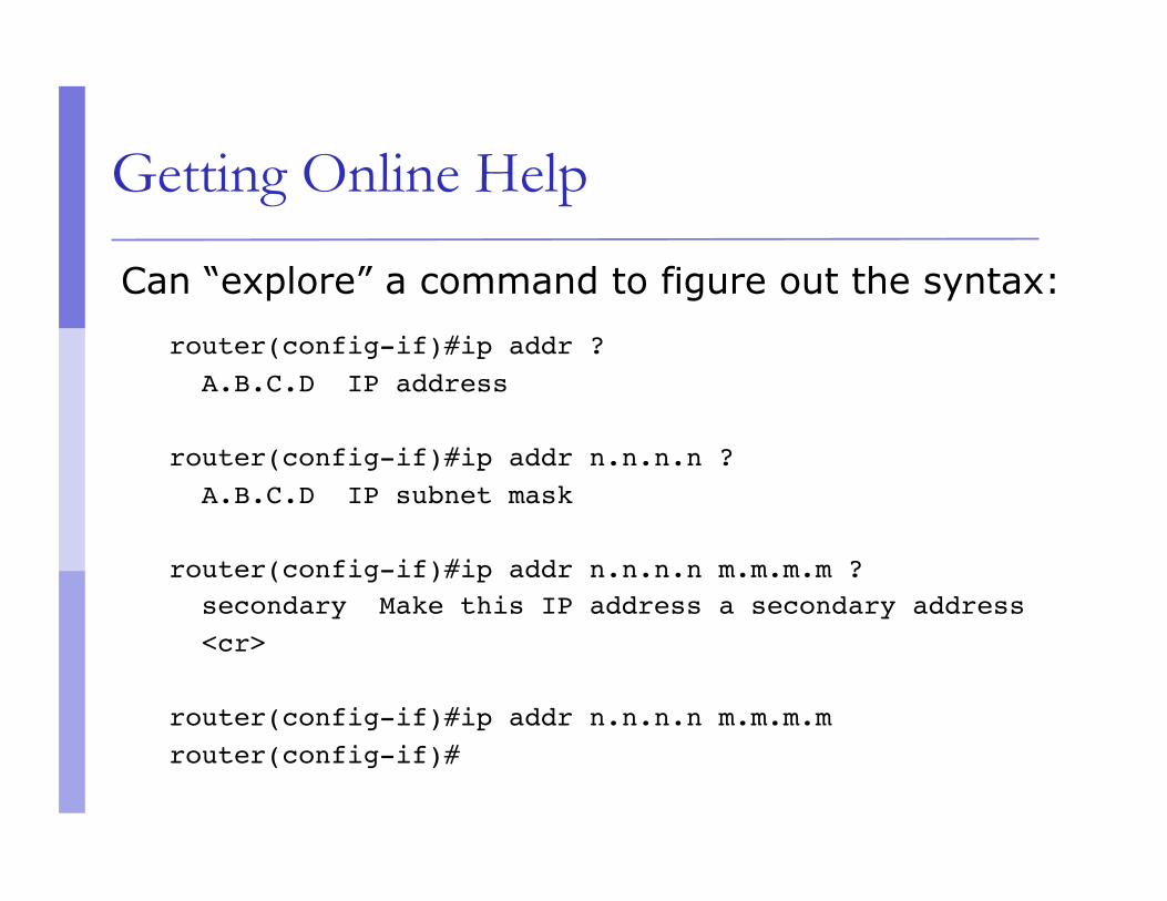
Getting Online Help
Can “explore” a command to figure out the syntax:
router(config-if)#ip addr ? A.B.C.D IP address
router(config-if)#ip addr n.n.n.n ? A.B.C.D IP subnet mask
router(config-if)#ip addr n.n.n.n m.m.m.m ? secondary Make this IP address a secondary address <cr>
router(config-if)#ip addr n.n.n.n m.m.m.m router(config-if)#

Getting Lazy Online Help
TAB character will complete a partial word hostel-rtr(config)#int<TAB> hostel-rtr(config)#interface et<TAB> hostel-rtr(config)#interface ethernet 0 hostel-rtr(config-if)#ip add<TAB> hostel-rtr(config-if)#ip address n.n.n.n m.m.m.m
Not really necessary; partial commands can be used: router#conf t router(config)#int fa0/0 router(config-if)#ip addr n.n.n.n
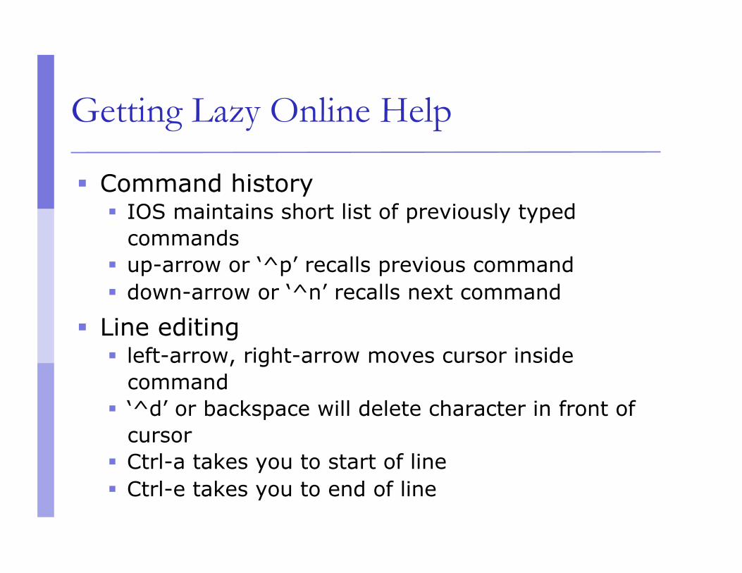
Getting Lazy Online Help
Command history IOS maintains short list of previously typed
commands up-arrow or ‘^p’ recalls previous command down-arrow or ‘^n’ recalls next command
Line editing left-arrow, right-arrow moves cursor inside
command ‘^d’ or backspace will delete character in front of
cursor Ctrl-a takes you to start of line Ctrl-e takes you to end of line
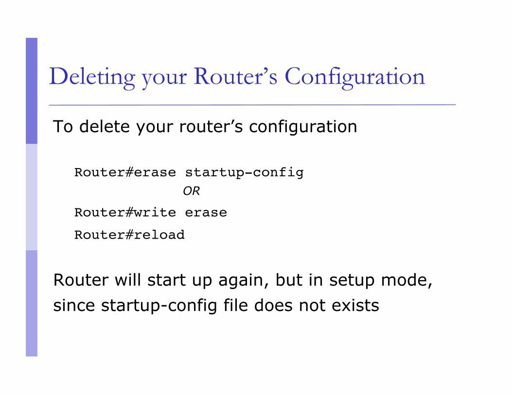
Deleting your Router’s Configuration
To delete your router’s configuration
Router#erase startup-config OR
Router#write erase
Router#reload
Router will start up again, but in setup mode, since startup-config file does not exists

Using Access Control Lists (ACLs)
Access Control Lists used to implement security in routers powerful tool for network control filter packets flow in or out of router interfaces restrict network use by certain users or devices deny or permit traffic
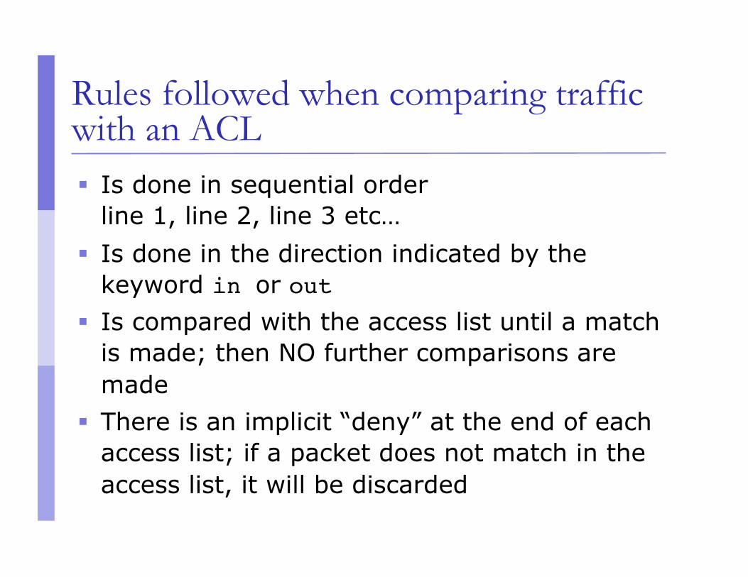
Rules followed when comparing traffic with an ACL Is done in sequential order
line 1, line 2, line 3 etc… Is done in the direction indicated by the
keyword in or out Is compared with the access list until a match
is made; then NO further comparisons are made
There is an implicit “deny” at the end of each access list; if a packet does not match in the access list, it will be discarded

Using ACLs
Standard IP Access Lists ranges (1 - 99) & (1300-1999) simpler address specifications generally permits or denies entire protocol suite
Extended IP Access Lists ranges (100 - 199) & (2000-2699) more complex address specification generally permits or denies specific protocols
There are also named access-lists Standard Extended Named access-lists easier to manage as lines may be deleted
or added by sequence number. NO need to delete and reinstall the entire ACL. Not supported with all features.

ACL Syntax
Standard IP Access List Configuration Syntax access-list access-list-number {permit | deny} source {source-mask}
ip access-group access-list-number {in | out}
Extended IP Access List Configuration Syntax access-list access-list-number {permit | deny} protocol source {source-mask} destination {destination-mask}
ip access-group access-list-number {in | out}
Named IP Access List Configuration Syntax ip access-list {standard | extended} {name | number}

Where to place ACLs
Place Standard IP access list close to destination
Place Extended IP access lists close to the source of the traffic you want to manage
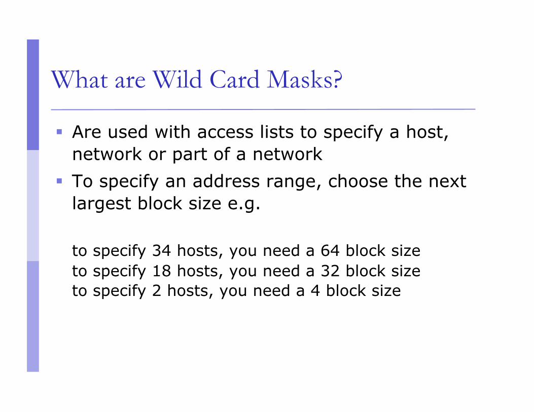
What are Wild Card Masks?
Are used with access lists to specify a host, network or part of a network
To specify an address range, choose the next largest block size e.g.
to specify 34 hosts, you need a 64 block size to specify 18 hosts, you need a 32 block size to specify 2 hosts, you need a 4 block size

What are Wild Card Masks?
Are used with the host/network address to tell the router a range of addresses to filter
Examples: To specify a host:
196.200.220.1 0.0.0.0
To specify a small subnet: 196.200.220.8 – 196.200.220.15 (would be a /29) Block size is 8, and wildcard is always one number less than the
block size Cisco access list then becomes 196.200.220.8 0.0.0.7
To specify all hosts on a /24 network: 196.200.220.0 0.0.0.255

What are Wild Card Masks?
Short cut method to a quick calculation of a network subnet to wildcard: 255 – {netmask bits on subnet mask}
Examples: to create wild card mask for 196.200.220.160
255.255.255.240 196.200.220.160 0.0.0.15 {255 – 240}
to create wild card mask for 196.200.220.0 255.255.252.0 196.200.220.0 0.0.3.255
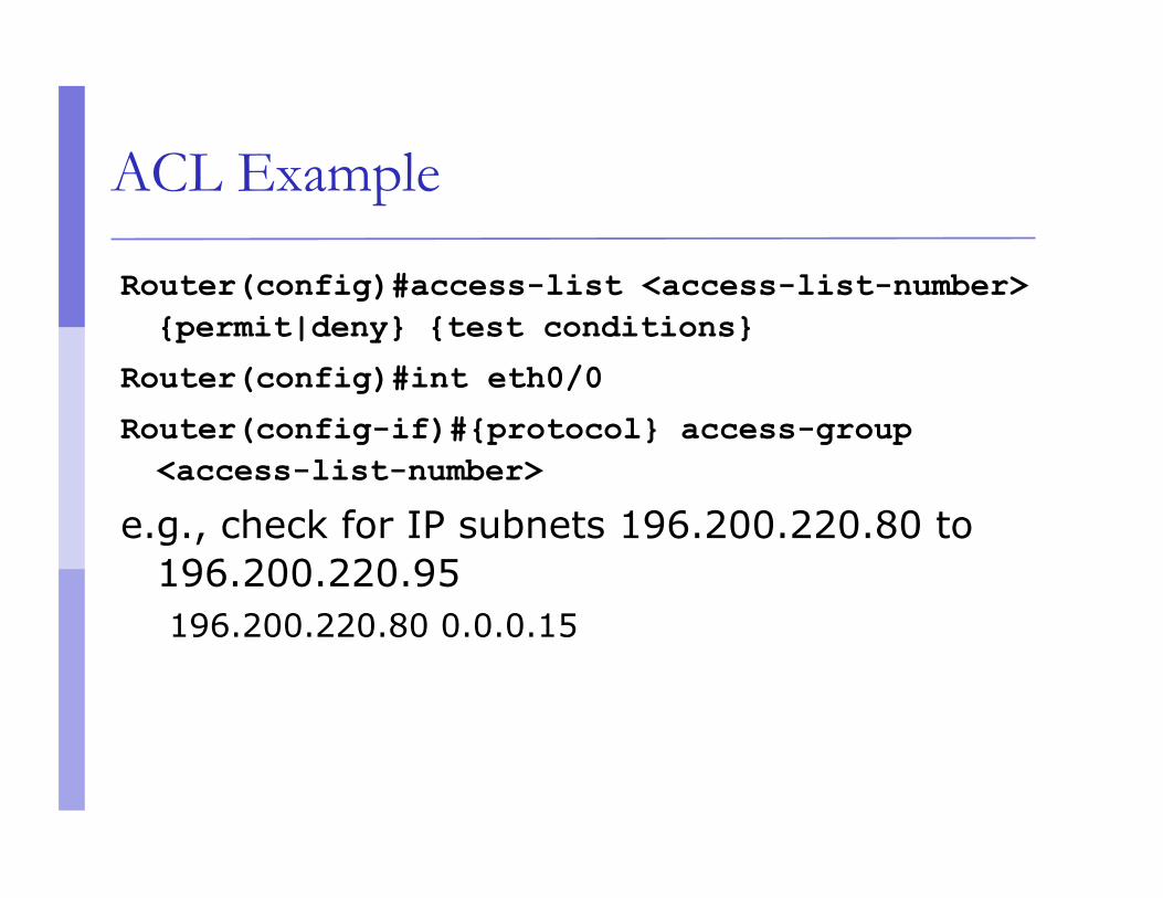
ACL Example
Router(config)#access-list <access-list-number> {permit|deny} {test conditions}
Router(config)#int eth0/0
Router(config-if)#{protocol} access-group <access-list-number>
e.g., check for IP subnets 196.200.220.80 to 196.200.220.95 196.200.220.80 0.0.0.15
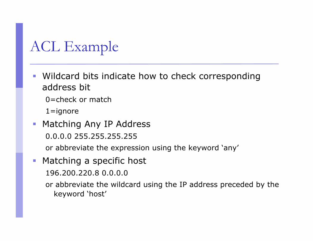
ACL Example
Wildcard bits indicate how to check corresponding address bit 0=check or match 1=ignore
Matching Any IP Address 0.0.0.0 255.255.255.255 or abbreviate the expression using the keyword ‘any’
Matching a specific host 196.200.220.8 0.0.0.0 or abbreviate the wildcard using the IP address preceded by the
keyword ‘host’

Permit telnet access only for my network
access-list 1 permit 196.200.220.192 0.0.0.15
access-list 1 deny any
line vty 0 4
access-class 1 in

Standard IP ACLs Permit only my network
Non 196.200.220.0
196.200.220.1 196.200.220.81
196.200.220.82 E0 S0
access-list 1 permit 196.200.220.80 0.0.0.15
interface ethernet 0 ip access-group 1 out interface serial 0 ip access-group 1 out
e0 s0

Extended IP ACLs: Deny FTP access through Interface E1
Non 196.200.220.0
196.200.220.10 196.200.220.225
196.200.220.226 E0 e1 S0
access-list 101 deny tcp 196.200.220.0 0.0.0.15 196.200.220.224 0.0.0.15 eq 21 access-list 101 deny tcp 196.200.220.0 0.0.0.15 196.200.220.224 0.0.0.15 eq 20 access-list 101 permit ip 196.200.220.0 0.0.0.15 0.0.0.0 255.255.255.255 interface ethernet 1 ip access-group 101 out
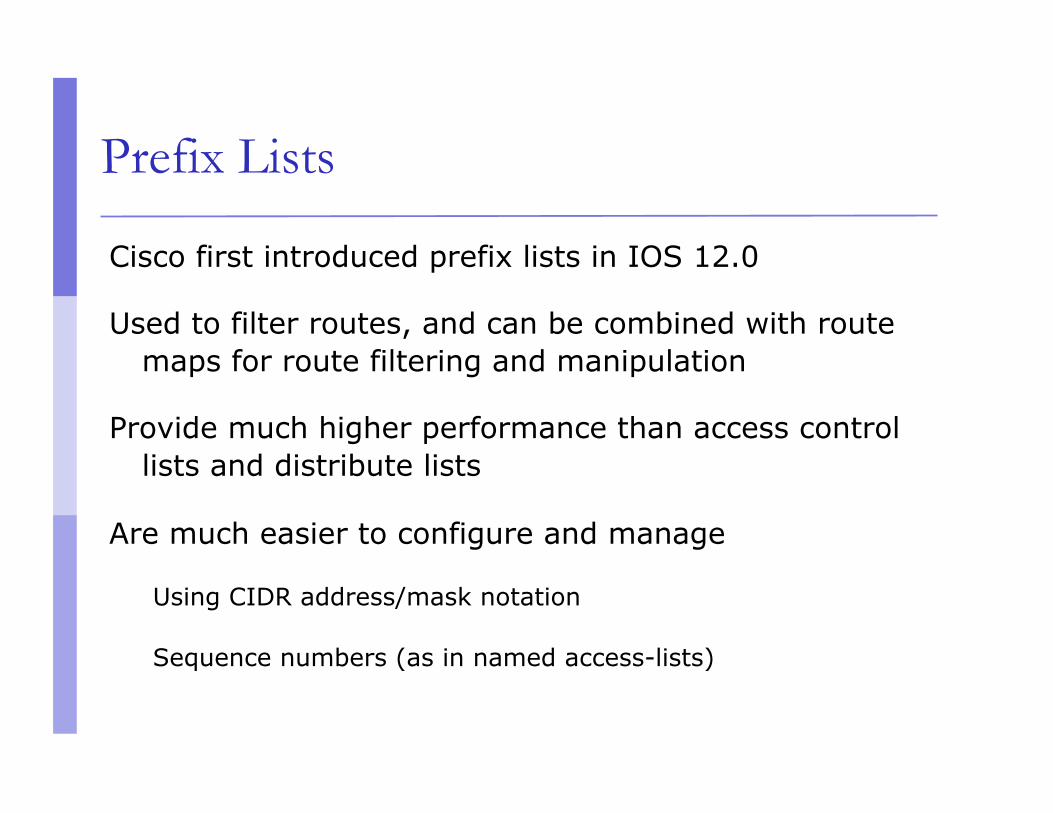
Prefix Lists
Cisco first introduced prefix lists in IOS 12.0
Used to filter routes, and can be combined with route maps for route filtering and manipulation
Provide much higher performance than access control lists and distribute lists
Are much easier to configure and manage
Using CIDR address/mask notation
Sequence numbers (as in named access-lists)

Prefix Lists
Prefix lists have an implicit “deny” at the end of them, like access control lists
Are quicker to process than regular access control lists
If you do have IOS 12.0 or later, it is STRONGLY RECOMMENDED to use prefix lists rather than access lists for route filtering and manipulation

Prefix List Configuration Syntax
Prefix list configuration syntax
config t ip prefix-list list-name {seq seq-value} {permit|deny} network/len {ge ge-value} {le le-value}
list-name – name to use for the prefix list seq-value – numeric value of the sequence; optional network/len – CIDR network address notation

Prefix List Configuration Syntax
Prefix list configuration Syntax
ge-value – “from” value of range; matches equal or longer prefixes (more bits in the prefix, smaller blocks of address space)
le-value – “to” value of range; matches equal or shorter prefixes (less bits in the prefix, bigger blocks of address space)
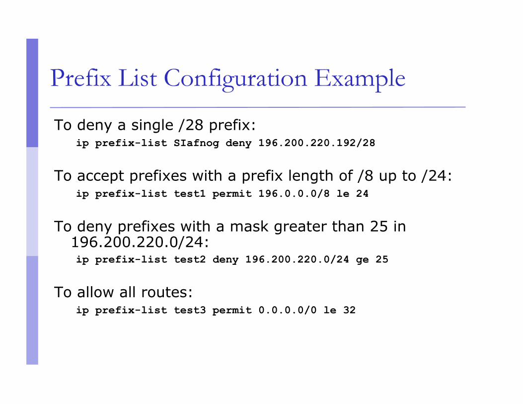
Prefix List Configuration Example
To deny a single /28 prefix: ip prefix-list SIafnog deny 196.200.220.192/28
To accept prefixes with a prefix length of /8 up to /24: ip prefix-list test1 permit 196.0.0.0/8 le 24
To deny prefixes with a mask greater than 25 in 196.200.220.0/24: ip prefix-list test2 deny 196.200.220.0/24 ge 25
To allow all routes: ip prefix-list test3 permit 0.0.0.0/0 le 32

Disaster Recovery – ROM Monitor
ROM Monitor is very helpful in recovering from emergency failures such as: Password recovery Upload new IOS into router with NO IOS installed Selecting a boot source and default boot filename Set console terminal baud rate to upload new IOS
quicker Load operating software from ROM Enable booting from a TFTP server

Getting to the ROM Monitor
Windows using HyperTerminal for the console session Ctrl-Break
FreeBSD/UNIX using Tip for the console session <Enter>, then ~# OR Ctrl-], then Break or Ctrl-C
Linux using Minicom for the console session Ctrl-A F
MacOS using Zterm for the console session Apple B
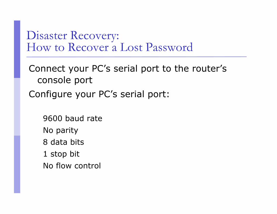
Disaster Recovery: How to Recover a Lost Password
Connect your PC’s serial port to the router’s console port
Configure your PC’s serial port:
9600 baud rate No parity 8 data bits 1 stop bit No flow control

Disaster Recovery: How to Recover a Lost Password
Your configuration register should be 0x2102; use “show version” command to check
Reboot the router and apply the Break-sequence within 60 seconds of powering the router, to put it into ROMMON mode
Rommon 1>confreg 0x2142 Rommon 2>reset
Router reboots, bypassing startup-config file
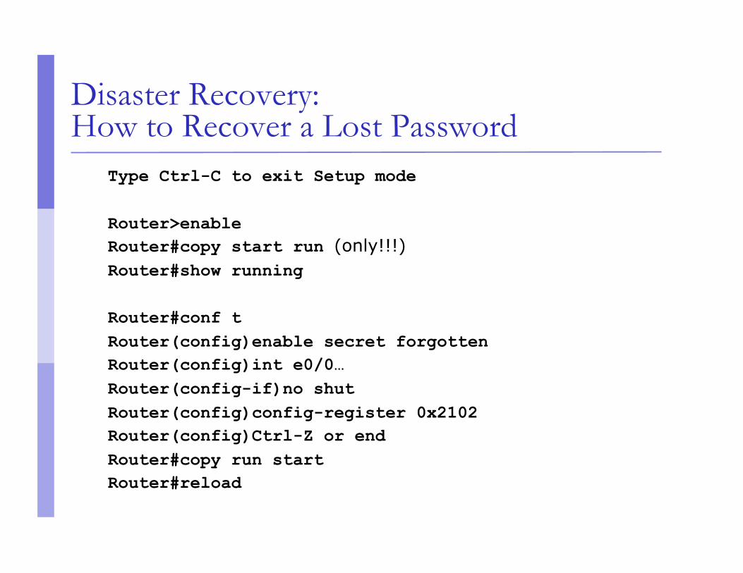
Disaster Recovery: How to Recover a Lost Password
Type Ctrl-C to exit Setup mode
Router>enable Router#copy start run (only!!!) Router#show running
Router#conf t Router(config)enable secret forgotten Router(config)int e0/0… Router(config-if)no shut Router(config)config-register 0x2102 Router(config)Ctrl-Z or end Router#copy run start Router#reload

Basic IPv6 Configuration

IPv6 Configuration
Enabling IPv6:
Router(config)# ipv6 unicast-routing
Disable Source Routing
Router(config)# no ipv6 source route
Activating IPv6 CEF
Router(config)# ipv6 cef

IPv6 Configuration - Interfaces
Configuring interfaces: A global or unique local IPv6 address:
Router(config-if)# ipv6 address X:X..X:X/prefix
An EUI-64 based IPv6 address (not a good idea on a router):
Router(config-if)# ipv6 address X:X::/prefix eui-64

IPv6 Configuration
Note that by configuring any IPv6 address on an interface, you will see a global or unique-local IPv6 address and a link-local IPv6 address on the interface Link-local IPv6 address format is:
FE80::interface-id
The local-link IPv6 address is constructed automatically by concatenating FE80 with Interface ID as soon as IPv6 is enabled on the interface:
Router(config-if)# ipv6 enable

IOS IPv6 Interface Status – Link Local Router1# conf t
Router1(config)# ipv6 unicast-routing
Router1(config)# ^Z
Router1#sh ipv6 interface
Ethernet0/0 is up, line protocol is up
IPv6 is enabled, link-local address is FE80::A8BB:CCFF:FE00:1E00
No global unicast address is configured
Joined group address(es):
FF02::1
FF02::2
FF02::1:FF00:1E00
MTU is 1500 bytes
ICMP error messages limited to one every 100 milliseconds
ICMP redirects are enabled
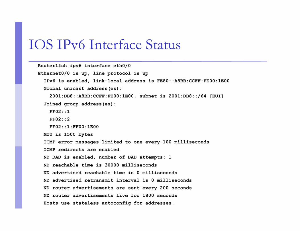
IOS IPv6 Interface Status Router1#sh ipv6 interface eth0/0
Ethernet0/0 is up, line protocol is up
IPv6 is enabled, link-local address is FE80::A8BB:CCFF:FE00:1E00
Global unicast address(es):
2001:DB8::A8BB:CCFF:FE00:1E00, subnet is 2001:DB8::/64 [EUI]
Joined group address(es):
FF02::1
FF02::2
FF02::1:FF00:1E00
MTU is 1500 bytes
ICMP error messages limited to one every 100 milliseconds
ICMP redirects are enabled
ND DAD is enabled, number of DAD attempts: 1
ND reachable time is 30000 milliseconds
ND advertised reachable time is 0 milliseconds
ND advertised retransmit interval is 0 milliseconds
ND router advertisements are sent every 200 seconds
ND router advertisements live for 1800 seconds
Hosts use stateless autoconfig for addresses.

IPv6 Configuration – Miscellaneous
Disable IPv6 redirects on interfaces
interface fastethernet 0/0 no ipv6 redirects
Nameserver, syslog etc can be IPv6 accessible
ip nameserver 2001:db8:2:1::2 ip nameserver 10.1.40.40
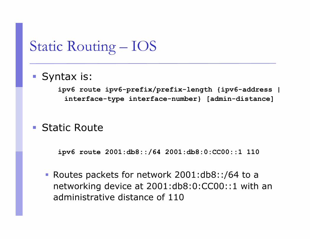
Static Routing – IOS
Syntax is: ipv6 route ipv6-prefix/prefix-length {ipv6-address | interface-type interface-number} [admin-distance]
Static Route
ipv6 route 2001:db8::/64 2001:db8:0:CC00::1 110
Routes packets for network 2001:db8::/64 to a networking device at 2001:db8:0:CC00::1 with an administrative distance of 110
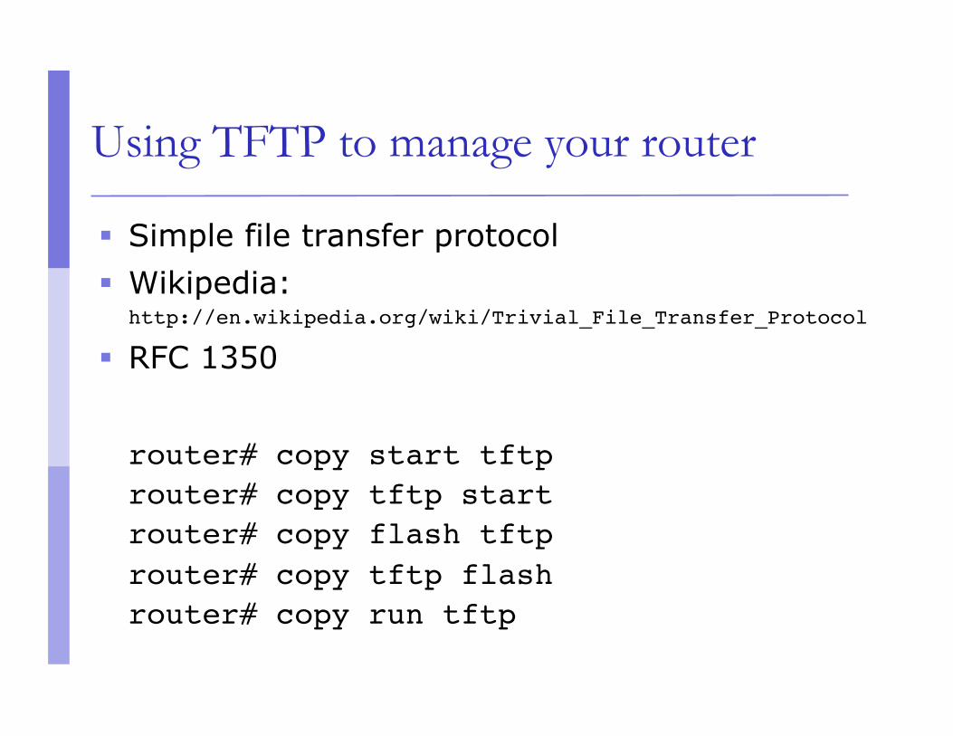
Using TFTP to manage your router
Simple file transfer protocol Wikipedia:
http://en.wikipedia.org/wiki/Trivial_File_Transfer_Protocol
RFC 1350
router# copy start tftp router# copy tftp startrouter# copy flash tftp router# copy tftp flashrouter# copy run tftp
Things to remember
Keep your server secure! Your TFTP server will typically have stored router
configs and IOS images. Therefore it's important that you restrict access to
your server. Setup integrity checking (even simple md5)
For large file transfers, consider using SCP/RCP

Other Alternatives?
router#conf network ? ftp: URL of source file http: URL of source file https: URL of source file pram: URL of source file rcp: URL of source file scp: URL of source file tftp: URL of source file <cr>