General Information - Autonerdz...General Information Sterling vehicles have a 12-volt, negative...
38
General Information Sterling vehicles have a 12-volt, negative ground electrical system. See Specifications 400 for a list of standard circuit numbers and circuit descriptions for vehicles built beginning February 27, 2001. Fuses and Circuit Breakers Sterling vehicles use blade-type fuses that have a transparent plastic housing enclosing the metal fuse element. A fuse is designed to melt the metal ele- ment at a certain amperage to protect the circuit wir- ing and components from damage due to an overcur- rent condition. The ampere rating of a fuse can be determined by reading the number molded into the top end of the fuse or by color. See Specifica- tions 400 for the fuse amperage rating and color for that amperage rating. Wire Color Code Colored wiring aids in the diagnosis and testing of electrical systems. It allows for faster identification when testing circuits for failure. See Specifica- tions 400 for a list of standard wiring color-coding information for vehicles built beginning February 27, 2001. In-Line Protection Devices In addition to the fuses in the fuse junction panel and the power distribution module (PDM), there may be in-line fuses in the wiring harnesses. The fuses are located in the battery cable wiring assembly and pro- vide power to the PDM fuses for the electrical, audio, and gauges in the cab. Two 10-gauge fuse links may be used on Sterling vehicles built before February 27, 2001: one is located between the starter motor battery terminal, the other is in the alternator wiring circuit protection. Fusible Links Fusible links are short lengths of wire that are smaller than the wires they are protecting. Fusible link wire is covered with a special, thick, non- flammable insulation. An overcurrent condition causes the insulation to blister and, if the overcurrent condition continues, the wire link will melt. To check a fusible link, look for blistered insulation. If the insu- lation is okay, pull lightly on the wire. If the fusible link insulation stretches, the wire has melted. Shielded Wires Shielding is necessary when a critical circuit is sus- ceptible to electromagnetic interference. Shielded wire has three conducting strands. The outermost strand is grounded, which creates a ground plane around the two inner conductors. Any interference that enters the shielded cable will be conducted to ground instead of affecting the circuit’s signal. Engine, Cab, and Trailer Wiring Sterling vehicles have two PDMs, one in the engine compartment and one in the cab. Both contain fuses, circuit breakers and relays used in the electrical system. Engine Wiring The engine compartment PDM has a decal identify- ing the location of the fuses, circuit breakers and re- lays on the outside of the PDM cover. See Fig. 1 for right-hand-drive vehicles, Fig. 2 for left-hand-drive vehicles built before February 27, 2001, or Fig. 3 for left-hand-drive vehicles built since February 27, 2001 but prior to September 12, 2003. Depending on ve- hicle options, fuse/circuit breaker/relay locations may vary from those shown. For fuse/circuit breaker/relay identification information, see Table 1 for right-hand- drive vehicles, Table 2 for left-hand-drive vehicles built before February 27, 2001, or Table 3 for left- hand-drive vehicles built since February 27, 2001 but prior to September 12, 2003. f542042 R1 R2 R3 R4 R5 R6 R7 R8 R9 R10 R11 R12 R13 R14 R15 R16 R17 R18 1 2 3 4 5 6 7 8 9 10 11 12 13 14 15 16 17 18 19 20 21 22 23 24 25 26 27 28 29 30 F F F F F F F F F F F F F F F F F F F F F F F F F F F F F F 09/23/99 Fig. 1, Engine Compartment PDM, Right-Hand-Drive Vehicles Wiring 54.13 General Information L-Line and A-Line Workshop Manual, Supplement 13, May 2004 050/1
Transcript of General Information - Autonerdz...General Information Sterling vehicles have a 12-volt, negative...
General InformationSterling vehicles have a 12-volt, negative groundelectrical system. See Specifications 400 for a listof standard circuit numbers and circuit descriptionsfor vehicles built beginning February 27, 2001.
Fuses and Circuit BreakersSterling vehicles use blade-type fuses that have atransparent plastic housing enclosing the metal fuseelement. A fuse is designed to melt the metal ele-ment at a certain amperage to protect the circuit wir-ing and components from damage due to an overcur-rent condition. The ampere rating of a fuse can bedetermined by reading the number molded into thetop end of the fuse or by color. See Specifica-tions 400 for the fuse amperage rating and color forthat amperage rating.
Wire Color CodeColored wiring aids in the diagnosis and testing ofelectrical systems. It allows for faster identificationwhen testing circuits for failure. See Specifica-tions 400 for a list of standard wiring color-codinginformation for vehicles built beginning February 27,2001.
In-Line Protection DevicesIn addition to the fuses in the fuse junction panel andthe power distribution module (PDM), there may bein-line fuses in the wiring harnesses. The fuses arelocated in the battery cable wiring assembly and pro-vide power to the PDM fuses for the electrical, audio,and gauges in the cab. Two 10-gauge fuse links maybe used on Sterling vehicles built before February27, 2001: one is located between the starter motorbattery terminal, the other is in the alternator wiringcircuit protection.
Fusible LinksFusible links are short lengths of wire that aresmaller than the wires they are protecting. Fusiblelink wire is covered with a special, thick, non-flammable insulation. An overcurrent conditioncauses the insulation to blister and, if the overcurrentcondition continues, the wire link will melt. To checka fusible link, look for blistered insulation. If the insu-lation is okay, pull lightly on the wire. If the fusiblelink insulation stretches, the wire has melted.
Shielded WiresShielding is necessary when a critical circuit is sus-ceptible to electromagnetic interference. Shieldedwire has three conducting strands. The outermoststrand is grounded, which creates a ground planearound the two inner conductors. Any interferencethat enters the shielded cable will be conducted toground instead of affecting the circuit’s signal.
Engine, Cab, and Trailer WiringSterling vehicles have two PDMs, one in the enginecompartment and one in the cab. Both contain fuses,circuit breakers and relays used in the electricalsystem.
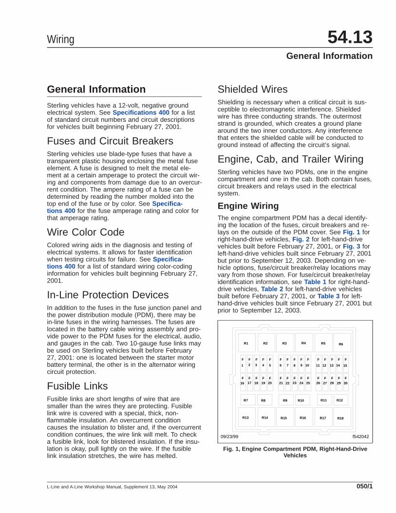
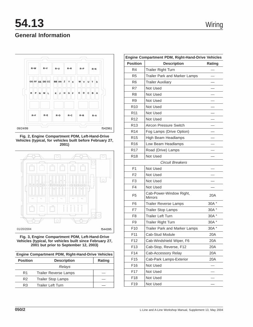
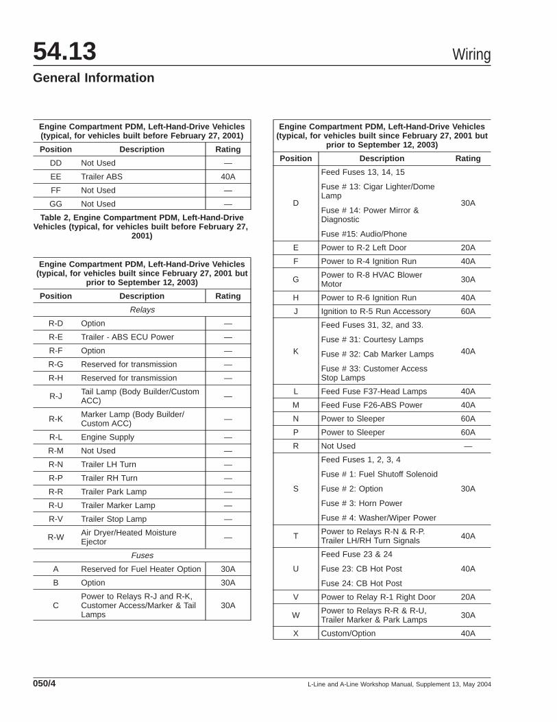
Engine WiringThe engine compartment PDM has a decal identify-ing the location of the fuses, circuit breakers and re-lays on the outside of the PDM cover. See Fig. 1 forright-hand-drive vehicles, Fig. 2 for left-hand-drivevehicles built before February 27, 2001, or Fig. 3 forleft-hand-drive vehicles built since February 27, 2001but prior to September 12, 2003. Depending on ve-hicle options, fuse/circuit breaker/relay locations mayvary from those shown. For fuse/circuit breaker/relayidentification information, see Table 1 for right-hand-drive vehicles, Table 2 for left-hand-drive vehiclesbuilt before February 27, 2001, or Table 3 for left-hand-drive vehicles built since February 27, 2001 butprior to September 12, 2003.
f542042
R1 R2 R3 R4 R5 R6
R7 R8 R9 R10 R11 R12
R13 R14 R15 R16 R17 R18
1 2 3 4 5 6 7 8 9 10 11 12 13 14 15
16 17 18 19 20 21 22 23 24 25 26 27 28 29 30
F F F F F F F F F F F F F F F
FFFFFFFFFFFFFFF
09/23/99
Fig. 1, Engine Compartment PDM, Right-Hand-DriveVehicles
Wiring 54.13General Information
L-Line and A-Line Workshop Manual, Supplement 13, May 2004 050/1
Engine Compartment PDM, Right-Hand-Drive Vehicles
Position Description Rating
Relays
R1 Trailer Reverse Lamps —
R2 Trailer Stop Lamps —
R3 Trailer Left Turn —
Engine Compartment PDM, Right-Hand-Drive Vehicles
Position Description Rating
R4 Trailer Right Turn —
R5 Trailer Park and Marker Lamps —
R6 Trailer Auxiliary —
R7 Not Used —
R8 Not Used —
R9 Not Used —
R10 Not Used —
R11 Not Used —
R12 Not Used —
R13 Aircon Pressure Switch —
R14 Fog Lamps (Drive Option) —
R15 High Beam Headlamps —
R16 Low Beam Headlamps —
R17 Road (Drive) Lamps —
R18 Not Used —
Circuit Breakers
F1 Not Used —
F2 Not Used —
F3 Not Used —
F4 Not Used —
F5 Cab-Power-Window Right,Mirrors 20A
F6 Trailer Reverse Lamps 30A *
F7 Trailer Stop Lamps 30A *
F8 Trailer Left Turn 30A *
F9 Trailer Right Turn 30A *
F10 Trailer Park and Marker Lamps 30A *
F11 Cab-Stud Module 20A
F12 Cab-Windshield Wiper, F6 20A
F13 Cab-Stop, Reverse, F12 20A
F14 Cab-Accessory Relay 20A
F15 Cab-Park Lamps-Exterior 20A
F16 Not Used —
F17 Not Used —
F18 Not Used —
F19 Not Used —
f542961
GG FF EE DD CC BB AA Z Y X W V U T S
ABCDEFGHJKLMNPR
R−F R−E R−D R−C R−B R−A
R−W R−V R−U R−R R−P R−N
09/24/99
Fig. 2, Engine Compartment PDM, Left-Hand-DriveVehicles (typical, for vehicles built before February 27,
2001)
01/20/2004 f544395
Fig. 3, Engine Compartment PDM, Left-Hand-DriveVehicles (typical, for vehicles built since February 27,
2001 but prior to September 12, 2003)
Wiring54.13General Information
L-Line and A-Line Workshop Manual, Supplement 13, May 2004050/2

Engine Compartment PDM, Right-Hand-Drive Vehicles
Position Description Rating
F20 Cab-Power-Window Left, DoorLocks 20A
F21 Fog Lamps (Drive Option) 20A *
F22 High Beam Headlamps 20A *
F23 Low Beam Headlamps 20A *
F24 Road (Drive) Lamps 20A *
F25 Trailer Auxiliary 20A *
F26 Cab-Customer Access 20A
F27 Cab-Lighting Control, Courtesy 20A
F28 Cab-Heater Aircon Blower Motor 30AMaxifuse
F29 Cab-Flasher Unit, Horn 20A
F30 Cab-Ignition Switch, Relay, FuelShutoff 20A
* Cycling Type (Automatic Reset)
Table 1, Engine Compartment PDM, Right-Hand-DriveVehicles
Engine Compartment PDM, Left-Hand-Drive Vehicles(typical, for vehicles built before February 27, 2001)
Position Description Rating
Relays
R-A Fuel Heater —
R-B Customer Access Park Lamps —
R-C Customer Access Marker Lamps —
R-D Not Used —
R-E Trailer ABS —
R-F Not Used —
R-N Trailer Left Turn Signal —
R-P Trailer Right Turn Signal —
R-R Trailer Park Lamps —
R-U Trailer Marker Lamps —
R-V Trailer Stop Lamps —
R-W Heated Moisture Ejectors —
Fuses
A Fuel Heater Relay R-A 40A
B Fuse 1 Fuel Solenoid 30A
Engine Compartment PDM, Left-Hand-Drive Vehicles(typical, for vehicles built before February 27, 2001)
Position Description Rating
C Customer Access, Marker andPark Lamp Relays R-B and R-C 40A
D
Fuse 13 Dome Lamp andLighter, Fuse 14 Mirrors andDiagnostic Connection, Fuse 15Audio/Phone
40A
E Left-Hand Power Window RelayR2 40A
FRun Relay R4, Fuse F36, Flash-to-Pass and Trailer HookupLamp
40A
G Heater/AC Blower Relay R8 40A
H Run Relay R6 40A
J Ignition Switch and Run/AccRelay R5 60A
KFuse 31 Courtesy Lamps, Fuse32 Cab Marker Lamps, Fuse 33Customer Access Stop Lamps
40A
L Headlamp Fuse 37 andHeadlamp Switch 40A
M ABS 40A
N Not Used —
P Not Used —
R Not Used —
S Fuse 3, Horns and C/B 4, Wiper 40A
T Trailer Turn Lamps Relay, R-Pand R-N 40A
U Fuses 23 and 24, CB Hot Posts 40A
V Right-Hand Power WindowRelay R1 40A
W Trailer Marker and Park LampsRelays, R-U, R-R 40A
X Customer Access, Stud "A",Instrument Panel 30A
Y Heated Moisture Ejectors 30A
Z Fuse 42, Turn Signals 40A
AA Customer Access, Run/ACCRelay R10 40A
BB Customer Access, Stud "H",Instrument Panel 30A
CC Trailer Stop Lamps Relay R-V 40A
Wiring 54.13General Information
L-Line and A-Line Workshop Manual, Supplement 13, May 2004 050/3
Engine Compartment PDM, Left-Hand-Drive Vehicles(typical, for vehicles built before February 27, 2001)
Position Description Rating
DD Not Used —
EE Trailer ABS 40A
FF Not Used —
GG Not Used —
Table 2, Engine Compartment PDM, Left-Hand-DriveVehicles (typical, for vehicles built before February 27,
2001)
Engine Compartment PDM, Left-Hand-Drive Vehicles(typical, for vehicles built since February 27, 2001 but
prior to September 12, 2003)
Position Description Rating
Relays
R-D Option —
R-E Trailer - ABS ECU Power —
R-F Option —
R-G Reserved for transmission —
R-H Reserved for transmission —
R-J Tail Lamp (Body Builder/CustomACC) —
R-K Marker Lamp (Body Builder/Custom ACC) —
R-L Engine Supply —
R-M Not Used —
R-N Trailer LH Turn —
R-P Trailer RH Turn —
R-R Trailer Park Lamp —
R-U Trailer Marker Lamp —
R-V Trailer Stop Lamp —
R-W Air Dryer/Heated MoistureEjector —
Fuses
A Reserved for Fuel Heater Option 30A
B Option 30A
CPower to Relays R-J and R-K,Customer Access/Marker & TailLamps
30A
Engine Compartment PDM, Left-Hand-Drive Vehicles(typical, for vehicles built since February 27, 2001 but
prior to September 12, 2003)
Position Description Rating
D
Feed Fuses 13, 14, 15
Fuse # 13: Cigar Lighter/DomeLamp
Fuse # 14: Power Mirror &Diagnostic
Fuse #15: Audio/Phone
30A
E Power to R-2 Left Door 20A
F Power to R-4 Ignition Run 40A
G Power to R-8 HVAC BlowerMotor 30A
H Power to R-6 Ignition Run 40A
J Ignition to R-5 Run Accessory 60A
K
Feed Fuses 31, 32, and 33.
Fuse # 31: Courtesy Lamps
Fuse # 32: Cab Marker Lamps
Fuse # 33: Customer AccessStop Lamps
40A
L Feed Fuse F37-Head Lamps 40A
M Feed Fuse F26-ABS Power 40A
N Power to Sleeper 60A
P Power to Sleeper 60A
R Not Used —
S
Feed Fuses 1, 2, 3, 4
Fuse # 1: Fuel Shutoff Solenoid
Fuse # 2: Option
Fuse # 3: Horn Power
Fuse # 4: Washer/Wiper Power
30A
T Power to Relays R-N & R-P.Trailer LH/RH Turn Signals 40A
U
Feed Fuse 23 & 24
Fuse 23: CB Hot Post
Fuse 24: CB Hot Post
40A
V Power to Relay R-1 Right Door 20A
W Power to Relays R-R & R-U,Trailer Marker & Park Lamps 30A
X Custom/Option 40A
Wiring54.13General Information
L-Line and A-Line Workshop Manual, Supplement 13, May 2004050/4
Engine Compartment PDM, Left-Hand-Drive Vehicles(typical, for vehicles built since February 27, 2001 but
prior to September 12, 2003)
Position Description Rating
Y Power to Relay RW-HeatedMoist/Dryer 30A
Z Feed Fuse 42, Stop Lamps andTurn Signals 40A
AA Power to Hydromax 40A
BB Customer Access, Stud "H",Instrument Panel 40A
CC Trailer Stop Lamps Relay R-V 40A
DD Not Used —
EE Power to Relay R-E: Trailer ABS 40A
FF Not Used —
GG Reserved for Engine 40A
HH Option Varied
JJ Option Varied
KK Option Varied
LL Battery Power Supply toTransmission ECU Varied
MM Ignition Power Supply to Engine Varied
NN Ignition Power Supply toTransmission ECU Varied
Table 3, Engine Compartment PDM, Left-Hand-DriveVehicles (typical, for vehicles built since February 27,
2001 but prior to September 12, 2003)
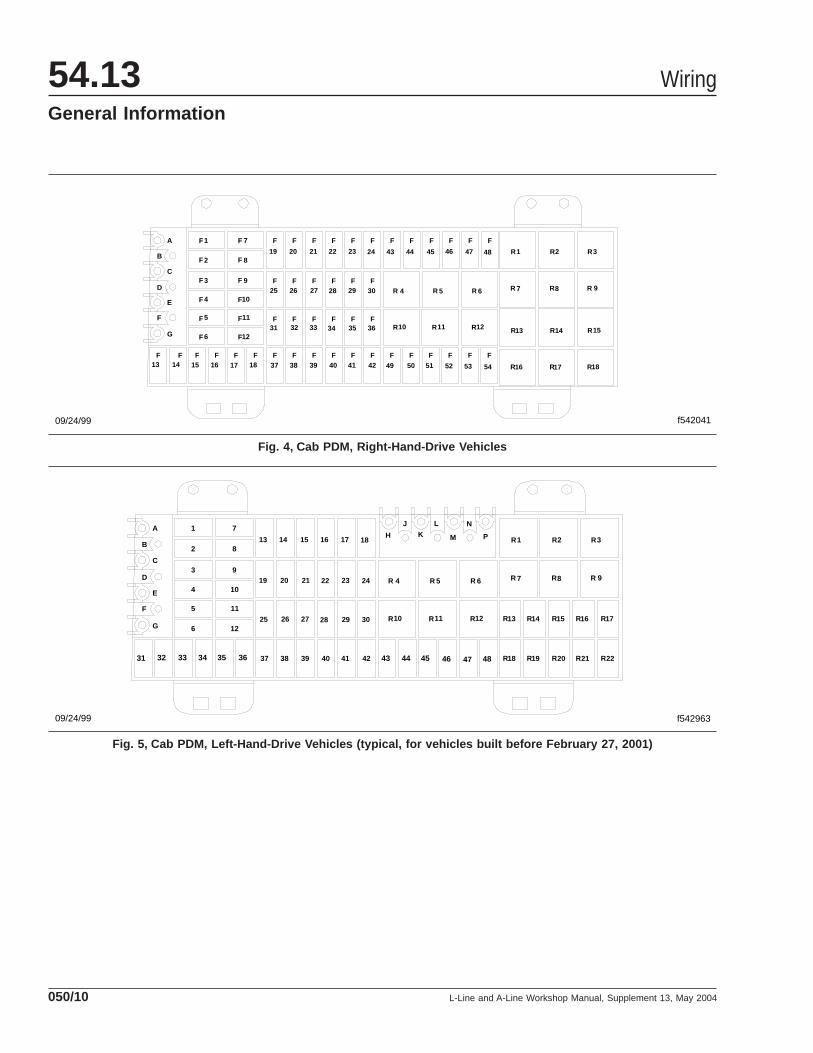
Cab WiringThe cab PDM is located on the passenger sidewithin the instrument panel. See Fig. 4 for right-hand-drive vehicles, Fig. 5 for left-hand-drive ve-hicles built before February 27, 2001, or Fig. 6 forleft-hand-drive vehicles built since February 27, 2001but prior to September 12, 2003. A trim panel coversthe PDM and is attached to the instrument panel byquarter-turn fasteners. A decal identifying the locationof the fuses, circuit breakers, and relays is attachedto the back side of the trim panel. For fuse/circuitbreaker/relay identification information, see Table 4for right-hand-drive vehicles, Table 5 for left-hand-drive vehicles built before February 27, 2001, orTable 6 for left-hand-drive vehicles built since Febru-ary 27, 2001 but prior to September 12, 2003.
Cab PDM, Right-Hand-Drive Vehicles
Position Description Rating
Circuit Breakers
F1 Left Power Window 18A *
F2 Power Door Locks 10A
F3 Right Power Window 18A *
F4 Power Mirrors 10A
F5 Windshield Wiper/Washer 11A *
F6 Not Used —
F7 Ignition Switch 10A
F8 Fuel Shutoff Relay 10A
F9 Not Used —
F10 Reverse Lamps 10A
F11 Stop Lamps 10A
F12 Not Used —
F13 Flasher Unit 10A
F14 Horn 10A
F15 Ignition Connection AntilockBrakes 5A
F16 Not Used —
F17 Customer-Constant 12V 10A
F18 Customer-Accessory 10A
F19 A/C-Blend Motor, Blower Relay 5A
F20 Cigar Lighter 10A
F21 Mirror Heater 10A
F22 Switch-Trailer Auxiliary,Customer 5A
F23 Not Used —
F24 Not Used —
F25 Air Intake Heater Module 10A
F26 Engine/Exhaust Brake 10A
F27 Warning Lamps 5A
F28 Fan Clutch Solenoid, A/CPressure Switch 5A
F29 Aircon Compressor 10A
F30 Air Switches 5A
F31 Clock Connection-Constant 12V 5A
F32 Dash Display, DiagnosticConnection 12V 5A
Wiring 54.13General Information
L-Line and A-Line Workshop Manual, Supplement 13, May 2004 050/5
Cab PDM, Right-Hand-Drive Vehicles
Position Description Rating
F33 Gauges 5A
F34 Clock, Road Speed Module-Ignition 5A
F35 Cruise Switch, DiagnosticConnection-Ignition 5A
F36 Not Used —
F37 Headlamp Switch 10A
F38 Flash-to-Pass Switch 5A
F39 Courtesy Lamps 10A
F40 Low Beam Relay Control 5A
F41 Park Relay Control 5A
F42 Fog Lamps Switch 5A
F43 Radio-Cassette-Constant 12V 5A
F44 Audio Connector-Constant 12V 5A
F45 Radio-Cassette-Accessory 5A
F46 Audio Connector-Accessory 5A
F47 Stud Module A-Constant 12V 10A
F48 Stud Module C-Constant 12V 10A
F49 High Beam Relay Control 5A
F50 Road Lamp Switch, High BeamIndicator Lamp 5A
F51 Park Lamps-Front and Rear 10A
F52 Park Lamps-Roof and Mirror 10A
F53 Park-Radio/Cassette, DashDisplay 5A
F54 Dimmer-Instrument Panel 10A
Relays
R1 Left Power Window —
R2 Right Power Window —
R3 Horn —
R4 Ignition CB25 to CB30 —
R5 Accessory CB19 to CB24 —
R6 Ignition-Stop, Reverse, CB12 —
R7 Interior Illumination —
R8 Blower Motor —
R9 Flasher —
R10 Accessory-Customer —
Cab PDM, Right-Hand-Drive Vehicles
Position Description Rating
R11 Windshield Wiper/Washer-Accessory —
R12 Fuel Shutoff —
R13 Audio-Accessory —
R14 Gauges/Electronics-Ignition —
R15 Engine Control Module-Ignition —
R16 Exterior Park Lamps —
R17 Not Used —
R18 Not Used —
Stud Module
A (AA)/Battery 12V/40A
B Accessory/Ignition —
C Ground 12V
D Not Used —
E Not Used —
F Not Used —
G Not Used —* Cycling Type (Automatic Reset)
Table 4, Cab PDM, Right-Hand-Drive Vehicles
Cab PDM, Left-Hand-Drive Vehicles (typical, forvehicles built before February 27, 2001)
Position Description Rating
Circuit Breakers
1 Fuel Shutoff Solenoid 10A
2 Not Used —
3 Horn Power 10A
4 Washer/Wiper Timer 11A *
5 Daytime Running Lights Module,High Beam Indicator 15A
6 Air Dryer, Instrument Panel AirValves, Trailer Stop Relay 10A
7 Air Intake Heater Module 10A
8 Two-Speed Axle, ABS Relay 15A
9 Exhaust/Engine Brake Solenoid,A/C Clutch, Allison ABS Relay 10A
10 Backup Lamps 10A
Wiring54.13General Information
L-Line and A-Line Workshop Manual, Supplement 13, May 2004050/6

Cab PDM, Left-Hand-Drive Vehicles (typical, forvehicles built before February 27, 2001)
Position Description Rating
11Pushbutton Start, Bulb CheckRelay, Warning Lamps, EtherSolenoid
20A
12 Engine Fan Control 10A
13 Cigar Lighter/Dome Lamps 15A
14 Power Mirrors, Datalink Power 10A
15 Audio, Cellular Phone (Battery) 20A
16 Audio Cellular Phone, SleeperRelay (Run/Accy) 10A
17 Heated Mirror, Power WindowRelay, Washer/Wiper Relay 25A
18 Heated Seats, Blend Door Motor,Blower Motor Relay 15A
19Electronic Transmission,Caterpillar 3126 AutomaticTransmission (Run)
5A
20 Electronic Engine Control (Start/Run) 15A
21 Warning Lamps, Fuel HeaterRelay 10A
22 Gauges, Speedometer, MessageCenter (Power) 10A
23 Hot Post Number 2 (InstrumentPanel or Header Console) 15A
24 Hot Post Number 1 (InstrumentPanel) 15A
25 Customer Accessory (Run/Accy) 25A
26 Not Used —
27 Detroit Diesel and CumminsElectronic Engines 15A
28 Electronic Engines
15A-Detroit
Diesel andCummins,
20A-Caterpillar
29 To Electronic Engines (Battery) 15A
30 Electronic AutomaticTransmission (Battery) 15A
31 Courtesy/Dome/Spot Lamps 15A
32 Door Locks, Horn Relay, MarkerLamps 15A
Cab PDM, Left-Hand-Drive Vehicles (typical, forvehicles built before February 27, 2001)
Position Description Rating
33 Customer Accessory StopLamps 15A
34 Left-Hand Power Window 18A *
35 Right-Hand Power Window 18A *
36 Flash-to-Pass, Trailer HookupLamps, Windshield Wipers 15A
37Instrument Panel Illumination,Park Lamps, Headlights,Customer Accessory Relay
15A
38 High Beam Indicator Lamp 5A
39 Fog/Road Lamps 10A
40 Left-Hand Turn Signal IndicatorLamp 5A
41 Right-Hand Turn Signal IndicatorLamp 5A
42 Turn Signals, Hazards 30A
43 Customer Access Front Left-Hand Turn Signal 5A
44 Customer Access Front Right-Hand Turn Signal 5A
45 Not Used —
46 Starter Relay, Air Intake Module,Ether Solenoid 20A
47 Not Used —
48 Two-Speed Axle Signal toSpeedometer 5A
Relays
R1 Right-Hand Power Window —
R2 Left-Hand Power Window —
R3 Two-Speed Axle —
R4 Run Relay —
R5 Run/Accessory —
R6 Run Relay —
R7 Fog/Road Lamps —
R8 Blower Motor —
R9 Turn Signal Flasher —
R10 Customer Access (Run/Accy) —
R11 Washer/Wiper —
R12 ABS Power —
Wiring 54.13General Information
L-Line and A-Line Workshop Manual, Supplement 13, May 2004 050/7
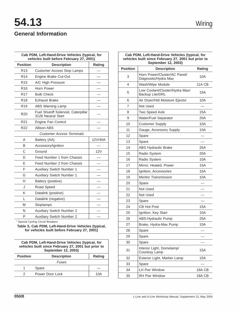
Cab PDM, Left-Hand-Drive Vehicles (typical, forvehicles built before February 27, 2001)
Position Description Rating
R13 Customer Access Stop Lamps —
R14 Engine Brake Cut-Out —
R15 A/C High Pressure —
R16 Horn Power —
R17 Bulb Check —
R18 Exhaust Brake —
R19 ABS Warning Lamp —
R20 Fuel Shutoff Solenoid, Caterpillar3126 Neutral Start —
R21 Engine Fan Control —
R22 Allison ABS —
Customer Access Terminals
A Battery (AA) 12V/40A
B Accessory/Ignition —
C Ground 12V
D Feed Number 1 from Chassis —
E Feed Number 2 from Chassis —
F Auxiliary Switch Number 1 —
G Auxiliary Switch Number 1 —
H Battery (positive) —
J Road Speed —
K Datalink (positive) —
L Datalink (negative) —
M Stoplamps —
N Auxiliary Switch Number 2 —
P Auxiliary Switch Number 2 —* Special Cycling Circuit Breakers
Table 5, Cab PDM, Left-Hand-Drive Vehicles (typical,for vehicles built before February 27, 2001)
Cab PDM, Left-Hand-Drive Vehicles (typical, forvehicles built since February 27, 2001 but prior to
September 12, 2003)
Position Description Rating
Fuses
1 Spare —
2 Power Door Lock 10A
Cab PDM, Left-Hand-Drive Vehicles (typical, forvehicles built since February 27, 2001 but prior to
September 12, 2003)
Position Description Rating
3 Horn Power/Cluster/AC Panel/Diagnostic/Hydra Max 10A
4 Wash/Wipe Module 11A CB
5 Low Coolant/Cluster/Hydra Max/Backup Lite/DRL 15A
6 Air Dryer/Htd Moisture Ejector 10A
7 Not Used —
8 Two Speed Axle 15A
9 Water/Fuel Separator 20A
10 Customer Supply 10A
11 Gauge, Accessory Supply 10A
12 Spare —
13 Spare —
14 ABS Hydraulic Brake 25A
15 Radio System 20A
16 Radio System 10A
17 Mirror, Heated, Power 15A
18 Ignition, Accessories 15A
19 Meritor Transmission 10A
20 Spare —
21 Not Used —
22 Not Used —
23 Spare —
24 CB Hot Post 15A
25 Ignition, Key Start 10A
26 ABS-Hydraulic Pump 25A
27 Brake, Hydra-Max Pump 10A
28 Spare —
29 Spare —
30 Spare —
31 Interior Light, Domelamp/Courtesy Lamp 15A
32 Exterior Light, Marker Lamp 15A
33 Spare —
34 LH Pwr Window 18A CB
35 RH Pwr Window 18A CB
Wiring54.13General Information
L-Line and A-Line Workshop Manual, Supplement 13, May 2004050/8
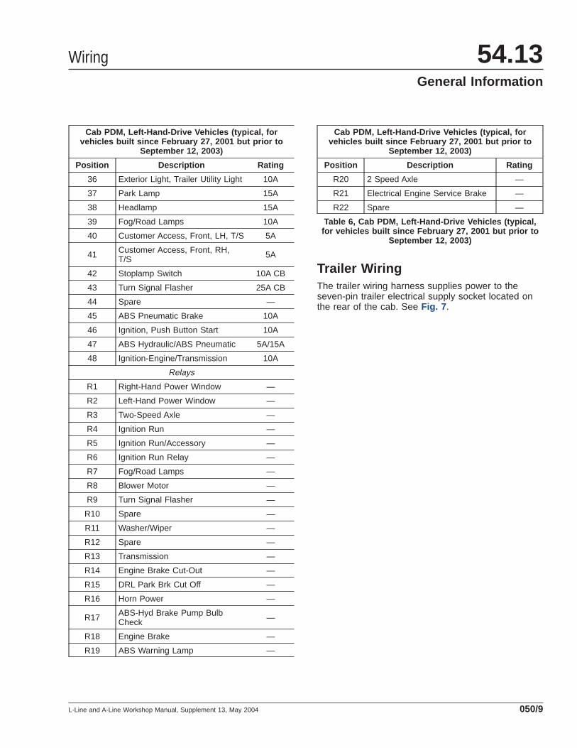
Cab PDM, Left-Hand-Drive Vehicles (typical, forvehicles built since February 27, 2001 but prior to
September 12, 2003)
Position Description Rating
36 Exterior Light, Trailer Utility Light 10A
37 Park Lamp 15A
38 Headlamp 15A
39 Fog/Road Lamps 10A
40 Customer Access, Front, LH, T/S 5A
41 Customer Access, Front, RH,T/S 5A
42 Stoplamp Switch 10A CB
43 Turn Signal Flasher 25A CB
44 Spare —
45 ABS Pneumatic Brake 10A
46 Ignition, Push Button Start 10A
47 ABS Hydraulic/ABS Pneumatic 5A/15A
48 Ignition-Engine/Transmission 10A
Relays
R1 Right-Hand Power Window —
R2 Left-Hand Power Window —
R3 Two-Speed Axle —
R4 Ignition Run —
R5 Ignition Run/Accessory —
R6 Ignition Run Relay —
R7 Fog/Road Lamps —
R8 Blower Motor —
R9 Turn Signal Flasher —
R10 Spare —
R11 Washer/Wiper —
R12 Spare —
R13 Transmission —
R14 Engine Brake Cut-Out —
R15 DRL Park Brk Cut Off —
R16 Horn Power —
R17 ABS-Hyd Brake Pump BulbCheck —
R18 Engine Brake —
R19 ABS Warning Lamp —
Cab PDM, Left-Hand-Drive Vehicles (typical, forvehicles built since February 27, 2001 but prior to
September 12, 2003)
Position Description Rating
R20 2 Speed Axle —
R21 Electrical Engine Service Brake —
R22 Spare —
Table 6, Cab PDM, Left-Hand-Drive Vehicles (typical,for vehicles built since February 27, 2001 but prior to
September 12, 2003)
Trailer WiringThe trailer wiring harness supplies power to theseven-pin trailer electrical supply socket located onthe rear of the cab. See Fig. 7 .
Wiring 54.13General Information
L-Line and A-Line Workshop Manual, Supplement 13, May 2004 050/9
A
C
E
G
F
D
B
1 7
2 8
3 9
4 10
5 11
6 12
37 38 39 40 41 42
4 5 6
1
7 8 9
2 3
10 11 12
f542041
19 20 21 22 23 24 43 44 45 46 47 48 R R R
R R R
R R R
R R R
13 14 15
16 17 18
R
R R R
R R
49 50 51 52 53 5413 14 15 16 17 18
25 26 27 28 29 30
31 32 33 34 35 36
09/24/99
F F F F F F F F F F F F
F F F F F F
F F F F F F F F F F F F F F F F F F
F
F
F
F
F
F F
F
F
F
F
F
F F F F F F
Fig. 4, Cab PDM, Right-Hand-Drive Vehicles
A
C
E
G
F
D
B
1 7
2 8
3 9
4 10
5 11
6 12
37 38 39 40 41 42
4 5 6
1
7 8 9
2 3
10 11 12
13 14 15 16 17 18 R R R
R R R
R13R
R R R
R R
19 20 21 22 23 24
25 26 27 28 29 30
PMKH
J L N
31 32 33 34 35 36 43 44 45 46 47 48
R14 R15 R16 R17
R18 R19 R20 R21 R22
09/24/99 f542963
Fig. 5, Cab PDM, Left-Hand-Drive Vehicles (typical, for vehicles built before February 27, 2001)
Wiring54.13General Information
L-Line and A-Line Workshop Manual, Supplement 13, May 2004050/10

01/16/2004 f544396
Fig. 6, Cab PDM, Left-Hand-Drive Vehicles (typical, for vehicles built since February 27, 2001 but prior to September12, 2003)
03/11/99 f430123
1
2
1. Electrical Connections Assembly2. Cover
Fig. 7, Trailer Electrical Connections Socket Location
Wiring 54.13General Information
L-Line and A-Line Workshop Manual, Supplement 13, May 2004 050/11
Wiring Repair Using PhillipsSTA-DRY® SolderlessConnectors
Parts and ToolsParts are available through the Parts DistributionCenters (PDCs) in packages of 25 connectors. Usethe connectors and adhesive lined shrinkable tubingshown in Table 1 when making a wiring splice.
Tools needed for wiring repair using solderless con-nectors include the following.
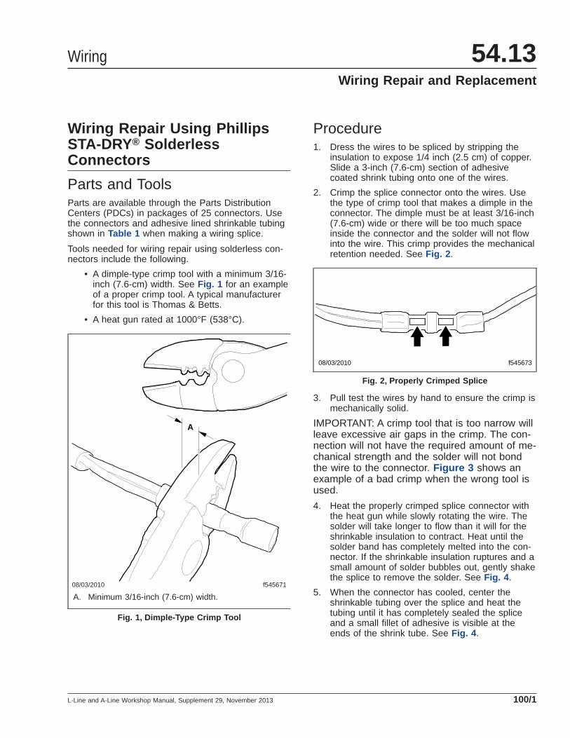
• A dimple-type crimp tool with a minimum 3/16-inch (7.6-cm) width. See Fig. 1 for an exampleof a proper crimp tool. A typical manufacturerfor this tool is Thomas & Betts.
• A heat gun rated at 1000°F (538°C).
Procedure1. Dress the wires to be spliced by stripping the
insulation to expose 1/4 inch (2.5 cm) of copper.Slide a 3-inch (7.6-cm) section of adhesivecoated shrink tubing onto one of the wires.
2. Crimp the splice connector onto the wires. Usethe type of crimp tool that makes a dimple in theconnector. The dimple must be at least 3/16-inch(7.6-cm) wide or there will be too much spaceinside the connector and the solder will not flowinto the wire. This crimp provides the mechanicalretention needed. See Fig. 2 .
3. Pull test the wires by hand to ensure the crimp ismechanically solid.
IMPORTANT: A crimp tool that is too narrow willleave excessive air gaps in the crimp. The con-nection will not have the required amount of me-chanical strength and the solder will not bondthe wire to the connector. Figure 3 shows anexample of a bad crimp when the wrong tool isused.
4. Heat the properly crimped splice connector withthe heat gun while slowly rotating the wire. Thesolder will take longer to flow than it will for theshrinkable insulation to contract. Heat until thesolder band has completely melted into the con-nector. If the shrinkable insulation ruptures and asmall amount of solder bubbles out, gently shakethe splice to remove the solder. See Fig. 4 .
5. When the connector has cooled, center theshrinkable tubing over the splice and heat thetubing until it has completely sealed the spliceand a small fillet of adhesive is visible at theends of the shrink tube. See Fig. 4 .
08/03/2010 f545671
A
A. Minimum 3/16-inch (7.6-cm) width.
Fig. 1, Dimple-Type Crimp Tool
08/03/2010 f545673
Fig. 2, Properly Crimped Splice
Wiring 54.13Wiring Repair and Replacement
L-Line and A-Line Workshop Manual, Supplement 29, November 2013 100/1
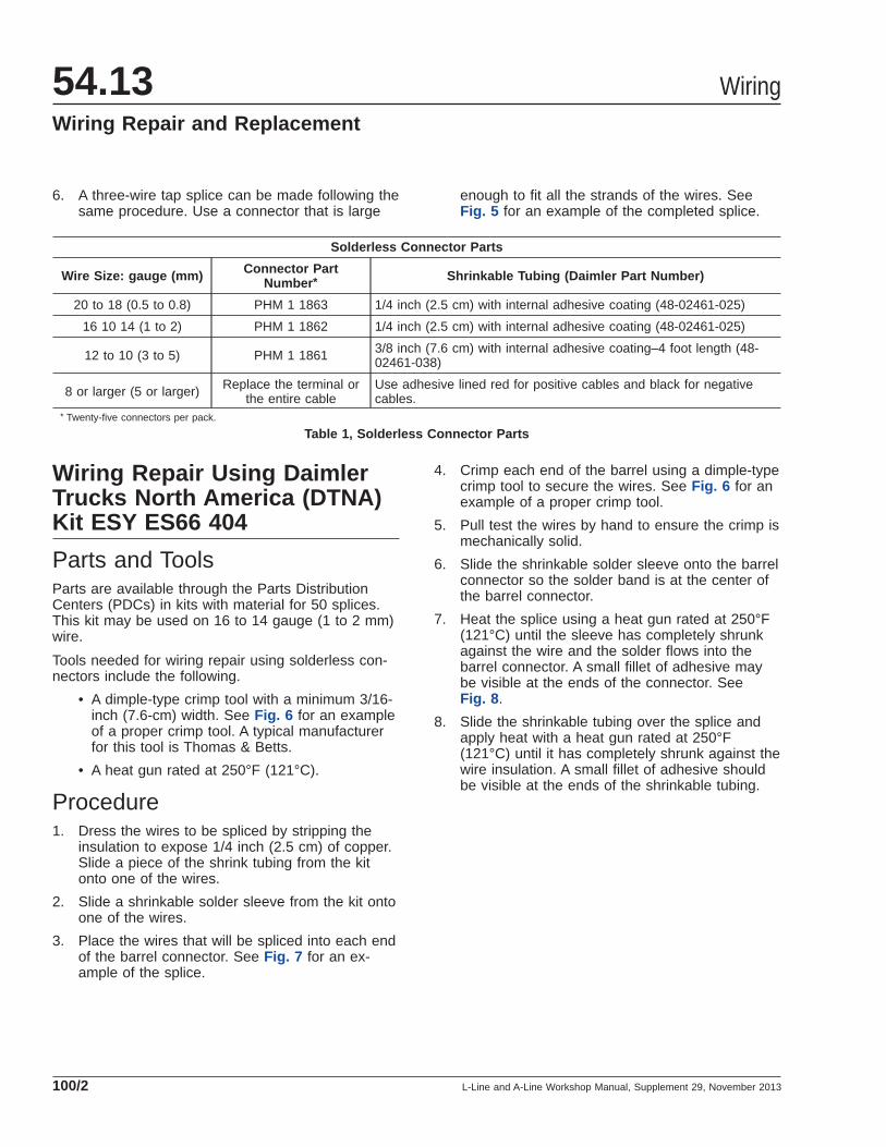
6. A three-wire tap splice can be made following thesame procedure. Use a connector that is large
enough to fit all the strands of the wires. SeeFig. 5 for an example of the completed splice.
Solderless Connector Parts
Wire Size: gauge (mm) Connector PartNumber * Shrinkable Tubing (Daimler Part Number)
20 to 18 (0.5 to 0.8) PHM 1 1863 1/4 inch (2.5 cm) with internal adhesive coating (48-02461-025)
16 10 14 (1 to 2) PHM 1 1862 1/4 inch (2.5 cm) with internal adhesive coating (48-02461-025)
12 to 10 (3 to 5) PHM 1 1861 3/8 inch (7.6 cm) with internal adhesive coating–4 foot length (48-02461-038)
8 or larger (5 or larger) Replace the terminal orthe entire cable
Use adhesive lined red for positive cables and black for negativecables.
* Twenty-five connectors per pack.
Table 1, Solderless Connector Parts
Wiring Repair Using DaimlerTrucks North America (DTNA)Kit ESY ES66 404
Parts and ToolsParts are available through the Parts DistributionCenters (PDCs) in kits with material for 50 splices.This kit may be used on 16 to 14 gauge (1 to 2 mm)wire.
Tools needed for wiring repair using solderless con-nectors include the following.
• A dimple-type crimp tool with a minimum 3/16-inch (7.6-cm) width. See Fig. 6 for an exampleof a proper crimp tool. A typical manufacturerfor this tool is Thomas & Betts.
• A heat gun rated at 250°F (121°C).
Procedure1. Dress the wires to be spliced by stripping the
insulation to expose 1/4 inch (2.5 cm) of copper.Slide a piece of the shrink tubing from the kitonto one of the wires.
2. Slide a shrinkable solder sleeve from the kit ontoone of the wires.
3. Place the wires that will be spliced into each endof the barrel connector. See Fig. 7 for an ex-ample of the splice.
4. Crimp each end of the barrel using a dimple-typecrimp tool to secure the wires. See Fig. 6 for anexample of a proper crimp tool.
5. Pull test the wires by hand to ensure the crimp ismechanically solid.
6. Slide the shrinkable solder sleeve onto the barrelconnector so the solder band is at the center ofthe barrel connector.
7. Heat the splice using a heat gun rated at 250°F(121°C) until the sleeve has completely shrunkagainst the wire and the solder flows into thebarrel connector. A small fillet of adhesive maybe visible at the ends of the connector. SeeFig. 8 .
8. Slide the shrinkable tubing over the splice andapply heat with a heat gun rated at 250°F(121°C) until it has completely shrunk against thewire insulation. A small fillet of adhesive shouldbe visible at the ends of the shrinkable tubing.
Wiring54.13Wiring Repair and Replacement
L-Line and A-Line Workshop Manual, Supplement 29, November 2013100/2
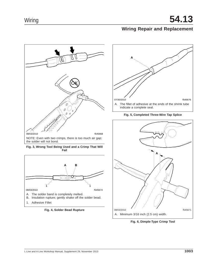
08/03/2010 f545668
OK
NOTE: Even with two crimps, there is too much air gap;the solder will not bond.
Fig. 3, Wrong Tool Being Used and a Crimp That WillFail
08/03/2010 f545674
A B
1 1
A. The solder band is completely melted.B. Insulation rupture; gently shake off the solder bead.
1. Adhesive Fillet
Fig. 4, Solder Bead Rupture
07/30/2010 f545676
A
A. The fillet of adhesive at the ends of the shrink tubeindicate a complete seal.
Fig. 5, Completed Three-Wire Tap Splice
08/03/2010 f545671
A
A. Minimum 3/16 inch (2.5 cm) width.
Fig. 6, Dimple-Type Crimp Tool
Wiring 54.13Wiring Repair and Replacement
L-Line and A-Line Workshop Manual, Supplement 29, November 2013 100/3
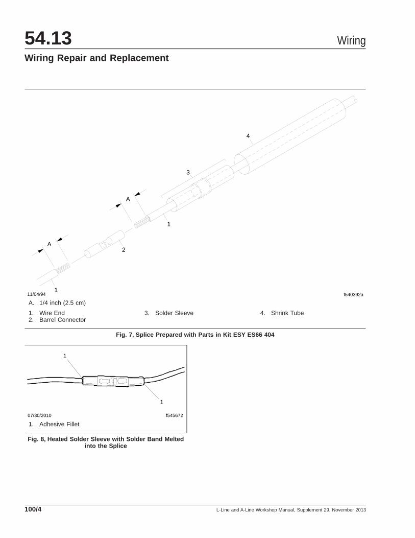
f540392a 1
2
1
3
4
A
A
11/04/94
A. 1/4 inch (2.5 cm)
1. Wire End2. Barrel Connector
3. Solder Sleeve 4. Shrink Tube
Fig. 7, Splice Prepared with Parts in Kit ESY ES66 404
07/30/2010 f545672
1
1
1. Adhesive Fillet
Fig. 8, Heated Solder Sleeve with Solder Band Meltedinto the Splice
Wiring54.13Wiring Repair and Replacement
L-Line and A-Line Workshop Manual, Supplement 29, November 2013100/4

Removal1. Park the vehicle on a level surface and set the
parking brake. Shut down the engine. Chock thetires.
2. Disconnect the batteries.
3. Remove the cover stud nuts retaining the coverto the cab.
4. Remove the cover. See Fig. 1 .
5. Remove the three screws holding the electricalsocket to the cover. See Fig. 2 .
6. Remove the housing cover from the electricalsocket and remove the cap.
7. Mark and disconnect the wires from the electricalsocket terminals.
Installation1. Connect the wires to the electrical socket termi-
nals.
2. Install the housing cover.
2.1 Insert the electrical socket into the hous-ing.
2.2 Tighten the three screws connecting theelectrical socket to the housing cover.See Fig. 2 .
3. Apply calking around the studs.
4. Slide the cover over the studs.
5. Install and tighten the nuts fastening the cover tothe cab.
6. Connect the batteries.
7. Remove the chocks from the tires.
03/11/99 f430123
1
2
1. Electrical Socket Assembly2. Cover
Fig. 1, Trailer Electrical Supply Socket Location
03/19/99
1
2
3 45
6
7
f542805
1. Harness2. Socket Housing3. Cover4. Grommet5. Socket Cover6. Cover-to-Electrical Socket Housing Screw (3 qty.)7. Nut
Fig. 2, Trailer Electrical Supply Socket andComponents
Wiring 54.13Trailer Electrical Supply Socket Removal and
Installation
L-Line and A-Line Workshop Manual, Supplement 4, January 2000 110/1

IMPORTANT: All figures are typical for vehiclesbuilt before February 27, 2001.
See Table 1 for fuse amperage ratings and colors foreach amperage rating.
See Table 2 for standard wiring color-coding informa-tion for vehicles built beginning February 27, 2001.
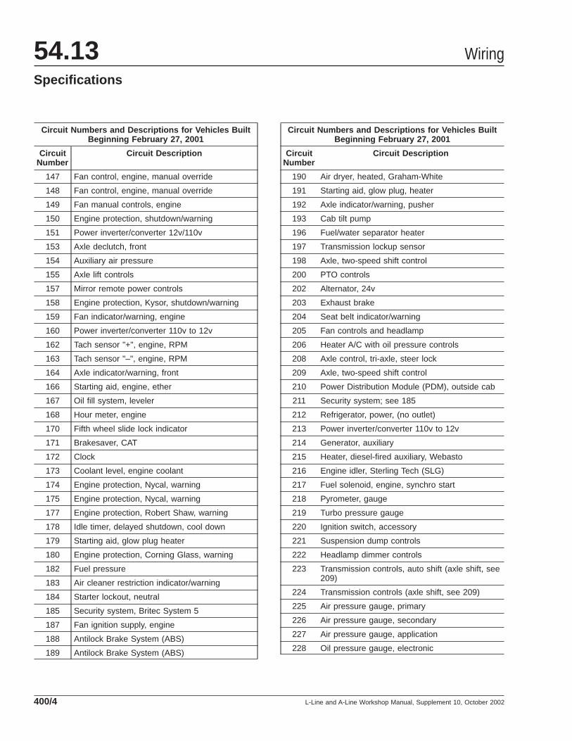
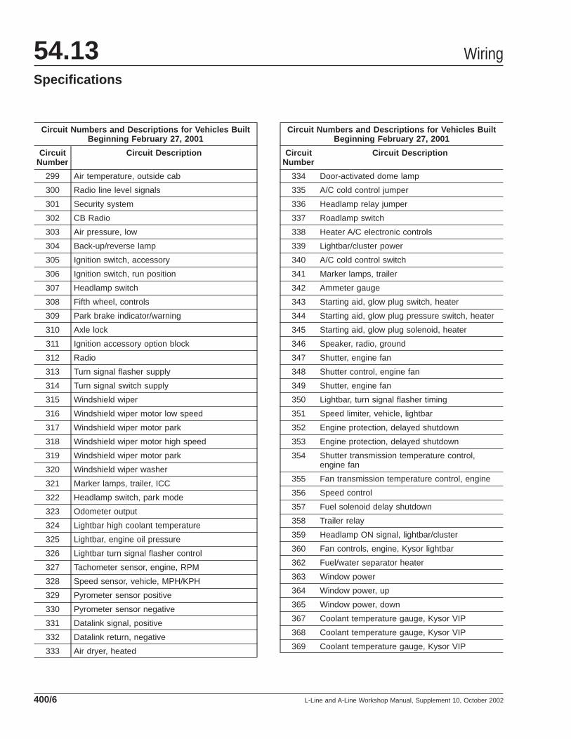
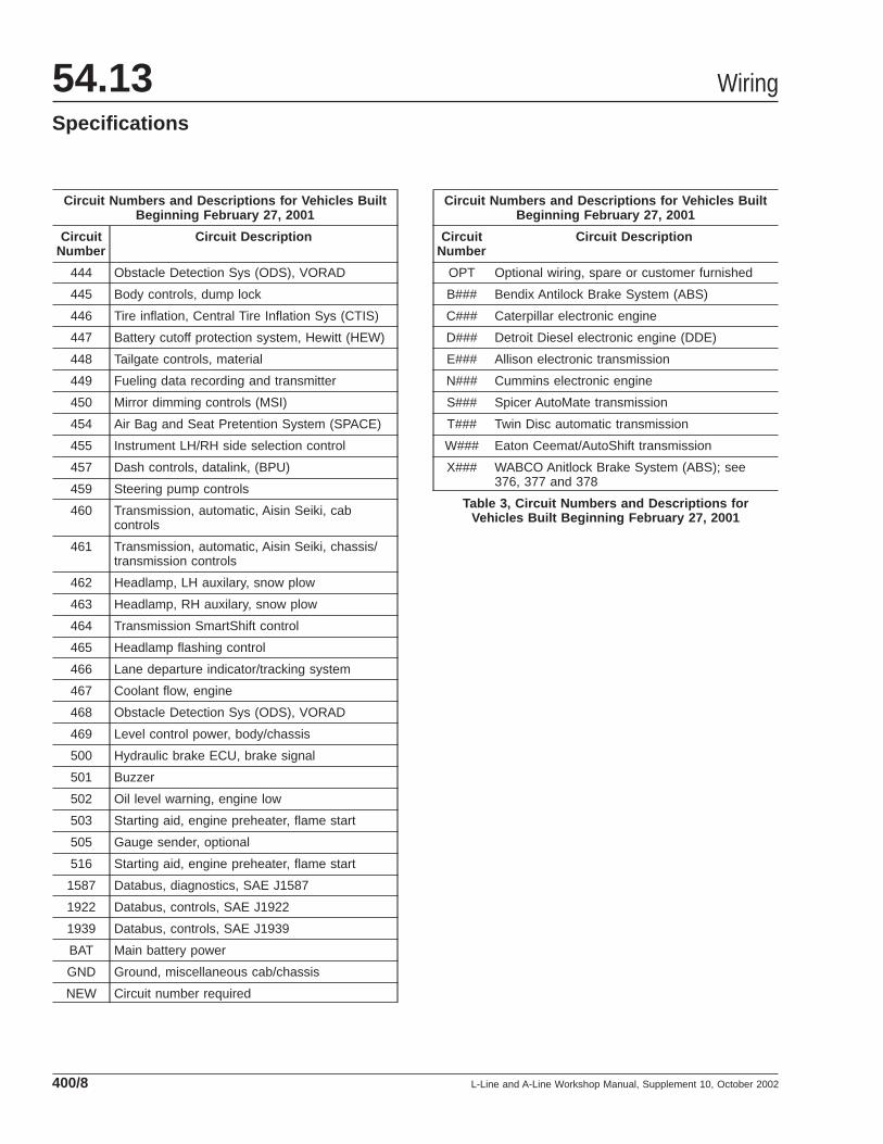
See Table 3 for circuit numbers and descriptions forvehicles built beginning February 27, 2001.
See Fig. 1 for a full view of the power distributionwiring.
See Fig. 2 and Fig. 3 for partial views of the powerdistribution wiring.
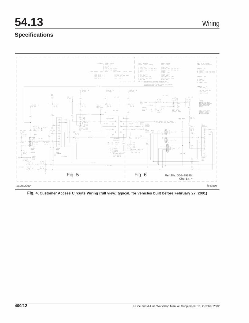
See Fig. 4 for a full view of the customer access cir-cuits wiring.
See Fig. 5 and Fig. 6 for partial views of the cus-tomer access circuits wiring.
See Fig. 7 for a full view of the instrument panel wir-ing.
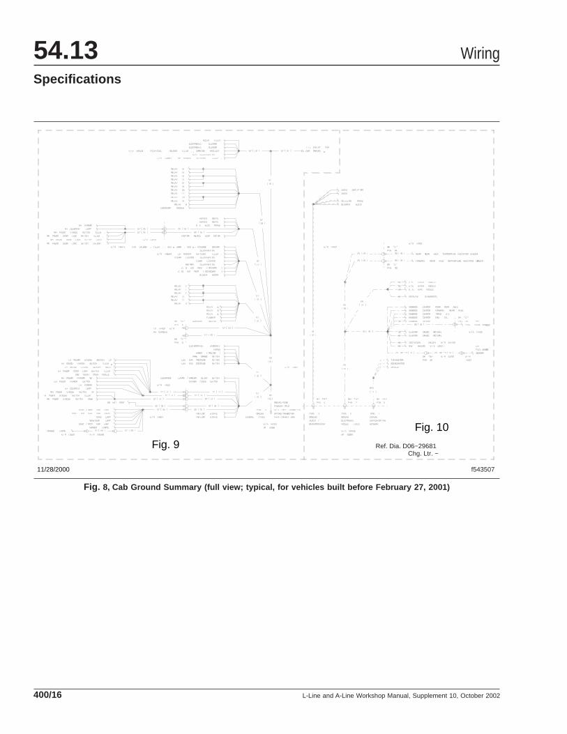
See Fig. 8 for a full view of the cab ground sum-mary.
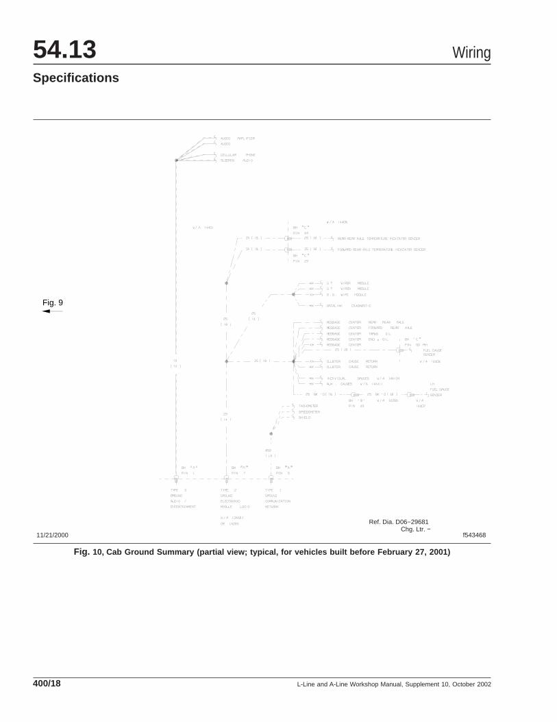
See Fig. 9 and Fig. 10 for partial views of the cabground summary.
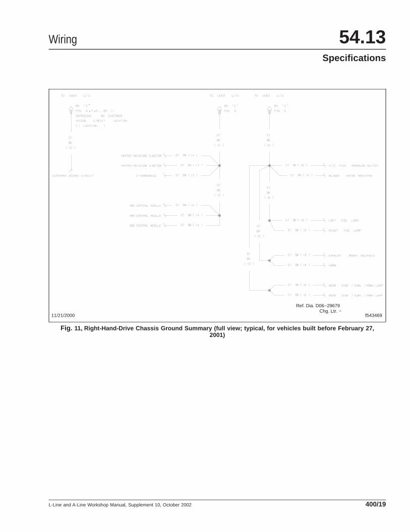
See Fig. 11 for a full view of the right-hand-drivechassis ground summary.
See Fig. 12 for a full view of the left-hand-drivechassis ground summary.
See Fig. 13 for bulkhead connector "A" pin and cir-cuit number identification.
See Fig. 14 for bulkhead connector "B" pin and cir-cuit number identification.
See Fig. 15 for bulkhead connector "C" pin and cir-cuit number identification.
Blade Fuse Color-Coding Chart
Ampere Rating Color
5A ATO Tan
10A ATO Red
15A ATO Light Blue
20A ATO Yellow
25A ATO Natural
30A ATO or Maxi Light Green
40A Maxi Amber
Table 1, Blade Fuse Color-Coding Chart
Standard Wiring Color-Coding for Vehicles Built Beginning February 27, 2001
Color Abbr Typical Usage
Black BK Ground, General
Black-White BK-W Ground, Clean or Isolated
Blue DK DKBL Backup/Windshield Wiper/Trailer Auxiliary
Blue LT LTBL HVAC/Circulation Fans/1922+
Blue LT-White LTBL-W Water, Oil Gauge and Indicator (Engine and Transmission)
Brown BR Marker, Tail and Panel Lamps
Gray GY Electronic Engine (or TXL Insulation)
Green DK DKG Turn Signal, RH/Driver’s Display/Data Record/1587+/1939–
Wiring 54.13Specifications
L-Line and A-Line Workshop Manual, Supplement 10, October 2002 400/1
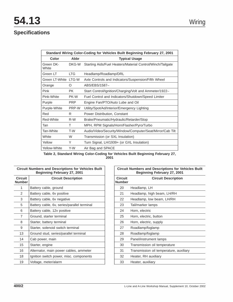
Standard Wiring Color-Coding for Vehicles Built Beginning February 27, 2001
Color Abbr Typical Usage
Green DK-White
DKG-W Starting Aids/Fuel Heaters/Material Control/Winch/Tailgate
Green LT LTG Headlamp/Roadlamp/DRL
Green LT-White LTG-W Axle Controls and Indicators/Suspension/Fifth Wheel
Orange O ABS/EBS/1587–
Pink PK Start Control/Ignition/Charging/Volt and Ammeter/1922–
Pink-White PK-W Fuel Control and Indicators/Shutdown/Speed Limiter
Purple PRP Engine Fan/PTO/Auto Lube and Oil
Purple-White PRP-W Utility/Spot/Ad/Interior/Emergency Lighting
Red R Power Distribution, Constant
Red-White R-W Brake/Pneumatic/Hydraulic/Retarder/Stop
Tan T MPH, RPM Signals/Horn/Flasher/Pyro/Turbo
Tan-White T-W Audio/Video/Security/Window/Computer/Seat/Mirror/Cab Tilt
White W Transmission (or SXL Insulation)
Yellow Y Turn Signal, LH/1939+ (or GXL Insulation)
Yellow-White Y-W Air Bag and SPACE
Table 2, Standard Wiring Color-Coding for Vehicles Built Beginning February 27,2001
Circuit Numbers and Descriptions for Vehicles BuiltBeginning February 27, 2001
CircuitNumber
Circuit Description
1 Battery cable, ground
2 Battery cable, 6v positive
3 Battery cable, 6v negative
5 Battery cable, 6v, series/parallel terminal
6 Battery cable, 12v positive
7 Ground, starter terminal
8 Starter, battery terminal
9 Starter, solenoid switch terminal
13 Ground stud, series/parallel terminal
14 Cab power, main
15 Starter, engine
16 Alternator, main power cables, ammeter
18 Ignition switch power, misc. components
19 Voltage, meter/alarm
Circuit Numbers and Descriptions for Vehicles BuiltBeginning February 27, 2001
CircuitNumber
Circuit Description
20 Headlamp, LH
21 Headlamp, high beam, LH/RH
22 Headlamp, low beam, LH/RH
23 Tail/marker lamps
24 Horn, electric
25 Horn, electric, button
26 Horn, electric, supply
27 Roadlamp/foglamp
28 Roadlamp/foglamp
29 Panel/instrument lamps
30 Transmission oil temperature
31 Transmission oil temperature, auxiliary
32 Heater, RH auxiliary
33 Heater, auxiliary
Wiring54.13Specifications
L-Line and A-Line Workshop Manual, Supplement 10, October 2002400/2

Circuit Numbers and Descriptions for Vehicles BuiltBeginning February 27, 2001
CircuitNumber
Circuit Description
34 Oil pressure, engine
35 Oil temperature, engine
36 Stop lamp
37 Turn signal flasher supply
38 Turn signal LH, EOF and trailer
39 Stop/turn combination lamp
40 Fan, windshield/sleeper
41 Dome lamp, interior
42 Axle oil temperature, forward
43 Axle oil temperature, rear
44 Axle oil temperature, center auxiliary
45 Receptacle, trailer
46 Marker/parking lamps
47 Fuel level
48 Fuel control and level, natural gas
52 Ignition switch and controls
54 Data recorder, speed and tach graph
55 Data recorder, speed and tach graph
57 Outlet, 12v power receptacle/cigar lighter
58 Heater, auxiliary
60 Turn signal, LH cab
61 Turn signal, RH cab
71 Ignition switch and controls
73 Utility lamp, back of cab
74 Starter mag switch/solenoid
75 Starter mag switch, ground, thermal protection
76 Mirror heat
77 Mirror heat, RH mirror supply
78 Spot lamp
80 Mirror heat, switch and controls
81 Ignition switch control devices
82 Starter mag switch, power supply
83 Alternator ground
84 Starting aid, glow plug heater
85 Starting aid, glow plug heater
Circuit Numbers and Descriptions for Vehicles BuiltBeginning February 27, 2001
CircuitNumber
Circuit Description
86 Axle lock, switch, interaxle
87 Axle lock
88 Lubrication system, automatic
90 Sander, road
91 Heater, diesel-fired auxiliary
94 Air dryer, heated
95 Speaker, radio
96 Oil level warning
97 Coolant level alarm, Perry
98 Heater A/C motor, blower
99 Fuel solenoid, engine run
101 Alternator control bus
102 Parking lamps
103 Parking lamps, RH
108 Door control dome lamp, LH
109 Door control dome lamp, RH
113 Baggage compartment lamps
116 Ground, cab stud
117 Speed sensor "+", vehicle, MPH/KPH
118 Speed sensor "–", vehicle, MPH/KPH
119 Coolant temperature, engine
120 Back-up/reverse lamp
121 Brake, engine/retarder/compression
122 Backup/reverse alarm
123 Alternator, voltage regulator/rectifier
124 Alternator regulator, ground
125 Park brake indicator/warning
130 Alternator/generator multi-voltage
131 Alternator "No Charge" indicator/warning
132 Alternator "No Charge" indicator/warning
137 Alternator "No Charge" indicator/warning
138 Starter lockout, alternator, ADLO
139 Starter lockout, alternator, ADLO
140 Oil pressure gauge, electronic
141 Starter lockout, alternator, ADLO
Wiring 54.13Specifications
L-Line and A-Line Workshop Manual, Supplement 10, October 2002 400/3
Circuit Numbers and Descriptions for Vehicles BuiltBeginning February 27, 2001
CircuitNumber
Circuit Description
147 Fan control, engine, manual override
148 Fan control, engine, manual override
149 Fan manual controls, engine
150 Engine protection, shutdown/warning
151 Power inverter/converter 12v/110v
153 Axle declutch, front
154 Auxiliary air pressure
155 Axle lift controls
157 Mirror remote power controls
158 Engine protection, Kysor, shutdown/warning
159 Fan indicator/warning, engine
160 Power inverter/converter 110v to 12v
162 Tach sensor "+", engine, RPM
163 Tach sensor "–", engine, RPM
164 Axle indicator/warning, front
166 Starting aid, engine, ether
167 Oil fill system, leveler
168 Hour meter, engine
170 Fifth wheel slide lock indicator
171 Brakesaver, CAT
172 Clock
173 Coolant level, engine coolant
174 Engine protection, Nycal, warning
175 Engine protection, Nycal, warning
177 Engine protection, Robert Shaw, warning
178 Idle timer, delayed shutdown, cool down
179 Starting aid, glow plug heater
180 Engine protection, Corning Glass, warning
182 Fuel pressure
183 Air cleaner restriction indicator/warning
184 Starter lockout, neutral
185 Security system, Britec System 5
187 Fan ignition supply, engine
188 Antilock Brake System (ABS)
189 Antilock Brake System (ABS)
Circuit Numbers and Descriptions for Vehicles BuiltBeginning February 27, 2001
CircuitNumber
Circuit Description
190 Air dryer, heated, Graham-White
191 Starting aid, glow plug, heater
192 Axle indicator/warning, pusher
193 Cab tilt pump
196 Fuel/water separator heater
197 Transmission lockup sensor
198 Axle, two-speed shift control
200 PTO controls
202 Alternator, 24v
203 Exhaust brake
204 Seat belt indicator/warning
205 Fan controls and headlamp
206 Heater A/C with oil pressure controls
208 Axle control, tri-axle, steer lock
209 Axle, two-speed shift control
210 Power Distribution Module (PDM), outside cab
211 Security system; see 185
212 Refrigerator, power, (no outlet)
213 Power inverter/converter 110v to 12v
214 Generator, auxiliary
215 Heater, diesel-fired auxiliary, Webasto
216 Engine idler, Sterling Tech (SLG)
217 Fuel solenoid, engine, synchro start
218 Pyrometer, gauge
219 Turbo pressure gauge
220 Ignition switch, accessory
221 Suspension dump controls
222 Headlamp dimmer controls
223 Transmission controls, auto shift (axle shift, see209)
224 Transmission controls (axle shift, see 209)
225 Air pressure gauge, primary
226 Air pressure gauge, secondary
227 Air pressure gauge, application
228 Oil pressure gauge, electronic
Wiring54.13Specifications
L-Line and A-Line Workshop Manual, Supplement 10, October 2002400/4

Circuit Numbers and Descriptions for Vehicles BuiltBeginning February 27, 2001
CircuitNumber
Circuit Description
229 Retarder, Telma (TLM)
230 Retarder, Telma (TLM)
231 Cab tilt alarm
232 Transmission controls, power harness
233 Retarder, transmission (Allison)
234 Fan controls, engine
235 Speed limiter, vehicle, Lenmar (LNM)
236 Transmission neutral indicator
237 Axle lock, auto, Meritor
238 PTO controls, Chelsea
239 Axle lock, auto, Meritor
240 Fuel/water separator indicator/warning
241 Data recorder, Sangamo tacho graph
242 Seat controls
243 Power inverter/converter
244 Speed limiter, vehicle, Hewitt
245 Engine protection, warning, P & N Co. (PNC)
246 Fuel pump, electric
248 Engine protection, shutdown, Ulanet Watchdog(ULN)
250 Cruise control, Bendix (BW)
251 Speed limiter, vehicle, Cummins Arrest (CUM)
252 Engine protection, shutdown, Lenmar (LNM)
253 Cab tilt indicator
254 Emergency lamp, beacon
255 Advertising lamp
256 Optional power wire
257 Windshield wiper delay
258 Fifth wheel, indicator
259 Alternator multi-voltage
260 Engine protection, shutdown, Murphy (MUR)
261 Axle lock, controlled differential
262 Retarder, transmission (Allison)
263 Engine protection, shutdown, Sterling Tech(SLG)
Circuit Numbers and Descriptions for Vehicles BuiltBeginning February 27, 2001
CircuitNumber
Circuit Description
264 Coolant level alarm, Webb (WEI)
265 Oil level warning, Webb (WEI)
266 PTO controls, transfer case
268 Gauge alarm, Murphy (MUR)
269 Speedometer, Engler (ENG)
270 Tachometer, Engler (ENG)
271 Oil pressure gauge, electronic
272 Transmission, deep reduction indicator
273 Axle oil temperature indicator, rear
274 Transmission oil temperature
275 TRW ETEC
276 Oil fill system, leveler, Webb (WEI)
277 Idle limiter, Kysor Idlestop (KYS)
278 Windshield wiper control, RH
279 Windshield wiper control, LH
280 Pyrometer alarm/shutdown, Hewitt (HEW)
281 Oil filter change indicator/warning
282 Engine protection, shutdown
283 Engine idler, cycler, Webb (WEI)
284 Oil filter change indicator/warning, Big Cam3
285 Suspension electrical/air controls
286 Fuel/water separator indicator/warning, Racor(RAI)
287 Tachometer, Sangamo (SNG)
288 Engine protection, alarm, Sterling Tech (SLG)
289 Transmission indicator, neutral
290 Engine protection, alarm, Hewitt (HEW)
291 Engine protection, warning, Webb (WEI)
292 Fuel tachometer, Flowscan (FOS), Argo (ARG)
293 Starting aid, engine, ether, Lubristart
294 Air tank auto-drain valve, SAB
295 Radio, AM/FM/CB
296 Fuel transfer pump
297 Data recorder warning buzzer
298 Fuel pressure gauge
Wiring 54.13Specifications
L-Line and A-Line Workshop Manual, Supplement 10, October 2002 400/5
Circuit Numbers and Descriptions for Vehicles BuiltBeginning February 27, 2001
CircuitNumber
Circuit Description
299 Air temperature, outside cab
300 Radio line level signals
301 Security system
302 CB Radio
303 Air pressure, low
304 Back-up/reverse lamp
305 Ignition switch, accessory
306 Ignition switch, run position
307 Headlamp switch
308 Fifth wheel, controls
309 Park brake indicator/warning
310 Axle lock
311 Ignition accessory option block
312 Radio
313 Turn signal flasher supply
314 Turn signal switch supply
315 Windshield wiper
316 Windshield wiper motor low speed
317 Windshield wiper motor park
318 Windshield wiper motor high speed
319 Windshield wiper motor park
320 Windshield wiper washer
321 Marker lamps, trailer, ICC
322 Headlamp switch, park mode
323 Odometer output
324 Lightbar high coolant temperature
325 Lightbar, engine oil pressure
326 Lightbar turn signal flasher control
327 Tachometer sensor, engine, RPM
328 Speed sensor, vehicle, MPH/KPH
329 Pyrometer sensor positive
330 Pyrometer sensor negative
331 Datalink signal, positive
332 Datalink return, negative
333 Air dryer, heated
Circuit Numbers and Descriptions for Vehicles BuiltBeginning February 27, 2001
CircuitNumber
Circuit Description
334 Door-activated dome lamp
335 A/C cold control jumper
336 Headlamp relay jumper
337 Roadlamp switch
338 Heater A/C electronic controls
339 Lightbar/cluster power
340 A/C cold control switch
341 Marker lamps, trailer
342 Ammeter gauge
343 Starting aid, glow plug switch, heater
344 Starting aid, glow plug pressure switch, heater
345 Starting aid, glow plug solenoid, heater
346 Speaker, radio, ground
347 Shutter, engine fan
348 Shutter control, engine fan
349 Shutter, engine fan
350 Lightbar, turn signal flasher timing
351 Speed limiter, vehicle, lightbar
352 Engine protection, delayed shutdown
353 Engine protection, delayed shutdown
354 Shutter transmission temperature control,engine fan
355 Fan transmission temperature control, engine
356 Speed control
357 Fuel solenoid delay shutdown
358 Trailer relay
359 Headlamp ON signal, lightbar/cluster
360 Fan controls, engine, Kysor lightbar
362 Fuel/water separator heater
363 Window power
364 Window power, up
365 Window power, down
367 Coolant temperature gauge, Kysor VIP
368 Coolant temperature gauge, Kysor VIP
369 Coolant temperature gauge, Kysor VIP
Wiring54.13Specifications
L-Line and A-Line Workshop Manual, Supplement 10, October 2002400/6

Circuit Numbers and Descriptions for Vehicles BuiltBeginning February 27, 2001
CircuitNumber
Circuit Description
370 Receptacle auxiliary terminal, trailer
371 Marker lamp, fender guides
372 Receptacle, heavy duty, trailer
373 Fuel solenoid, engine run
374 Starter lockout
375 Daylight Running Lamps (DRL), neutral
376 Antilock Brake System (ABS) controls
377 Antilock Brake System (ABS) sensors
378 Antilock Brake System (ABS) valves
379 Daylight Running Lamps (DRL)
380 Daylight Running Lamps (DRL)
381 Daylight Running Lamps (DRL)
382 Daylight Running Lamps (DRL), LH headlamp
383 Daylight Running Lamps (DRL), RH headlamp
384 Daylight Running Lamps (DRL), program
385 Daylight Running Lamps (DRL), controls
386 Daylight Running Lamps (DRL), LH headlamp
387 Daylight Running Lamps (DRL), RH headlamp
388 Hydraulic brake power
389 Hydraulic brake relay
390 Hydraulic brake lamp
391 Hydraulic brake relay
392 Hydraulic brake motor
393 Hydraulic brake flow/relay
394 Hydraulic brake, park brake lamp
395 Hydraulic brake fluid sensor
396 Hydraulic brake buzzer/alarm
397 Hydraulic brake cab door signal
398 Hydraulic brake motor sense
399 Optional wire, cab/chassis, customer furnished
400 Optional wire, cab/chassis, customer furnished
401 Block coolant heater, Truck Comfort Sys (TCS)
403 Fuel restriction indicator, Hewitt (HEW)
404 Data recorder, ARI Trip
405 Data recorder
Circuit Numbers and Descriptions for Vehicles BuiltBeginning February 27, 2001
CircuitNumber
Circuit Description
406 Emergency lamp, alternating flashing
407 Emergency lamp, cross-fire lights
408 Emergency lamp, alley lights
409 Emergency lamp, bin lights
410 Emergency siren
411 Emergency fire truck miscellaneous
412 Data recorder, Isspro (ISP)
414 Tracking system, vehicle, Sony Geostrat RGSS
415 Idle governor, high
416 Refrigerator/television power, (no outlet)
417 Phone power, mobile
418 Tool box lamp, LH
419 Tool box lamp, RH
420 Military 24v lighting, blackout
421 Military 24v lighting, blackout
422 Military auxilliary 24v heater
423 Military, winch controls
424 Headlamp wiper/washer
425 Battery cutoff switch controls and bypass
426 Air inside/outside indicator
427 Tracking system, vehicle, satellite
428 Battery isolator protection system
429 Pyrometer alarm/warning
430 Windshield wiper heater
431 Starting aid, engine preheater, grid/flame
432 Seat controls
433 Data recorder, Data Hub (DDE)
434 Suspension controls, ECAS
435 Seat belt indicator/warning
436 Camera, rear and side view
437 Instrumentation Control Unit (ICU), dash display
439 Electronic engine ECU
440 Electronic engine ECU
442 Data recorder, Data Logger Unit (DLU)
443 Door lock
Wiring 54.13Specifications
L-Line and A-Line Workshop Manual, Supplement 10, October 2002 400/7
Circuit Numbers and Descriptions for Vehicles BuiltBeginning February 27, 2001
CircuitNumber
Circuit Description
444 Obstacle Detection Sys (ODS), VORAD
445 Body controls, dump lock
446 Tire inflation, Central Tire Inflation Sys (CTIS)
447 Battery cutoff protection system, Hewitt (HEW)
448 Tailgate controls, material
449 Fueling data recording and transmitter
450 Mirror dimming controls (MSI)
454 Air Bag and Seat Pretention System (SPACE)
455 Instrument LH/RH side selection control
457 Dash controls, datalink, (BPU)
459 Steering pump controls
460 Transmission, automatic, Aisin Seiki, cabcontrols
461 Transmission, automatic, Aisin Seiki, chassis/transmission controls
462 Headlamp, LH auxilary, snow plow
463 Headlamp, RH auxilary, snow plow
464 Transmission SmartShift control
465 Headlamp flashing control
466 Lane departure indicator/tracking system
467 Coolant flow, engine
468 Obstacle Detection Sys (ODS), VORAD
469 Level control power, body/chassis
500 Hydraulic brake ECU, brake signal
501 Buzzer
502 Oil level warning, engine low
503 Starting aid, engine preheater, flame start
505 Gauge sender, optional
516 Starting aid, engine preheater, flame start
1587 Databus, diagnostics, SAE J1587
1922 Databus, controls, SAE J1922
1939 Databus, controls, SAE J1939
BAT Main battery power
GND Ground, miscellaneous cab/chassis
NEW Circuit number required
Circuit Numbers and Descriptions for Vehicles BuiltBeginning February 27, 2001
CircuitNumber
Circuit Description
OPT Optional wiring, spare or customer furnished
B### Bendix Antilock Brake System (ABS)
C### Caterpillar electronic engine
D### Detroit Diesel electronic engine (DDE)
E### Allison electronic transmission
N### Cummins electronic engine
S### Spicer AutoMate transmission
T### Twin Disc automatic transmission
W### Eaton Ceemat/AutoShift transmission
X### WABCO Anitlock Brake System (ABS); see376, 377 and 378
Table 3, Circuit Numbers and Descriptions forVehicles Built Beginning February 27, 2001
Wiring54.13Specifications
L-Line and A-Line Workshop Manual, Supplement 10, October 2002400/8
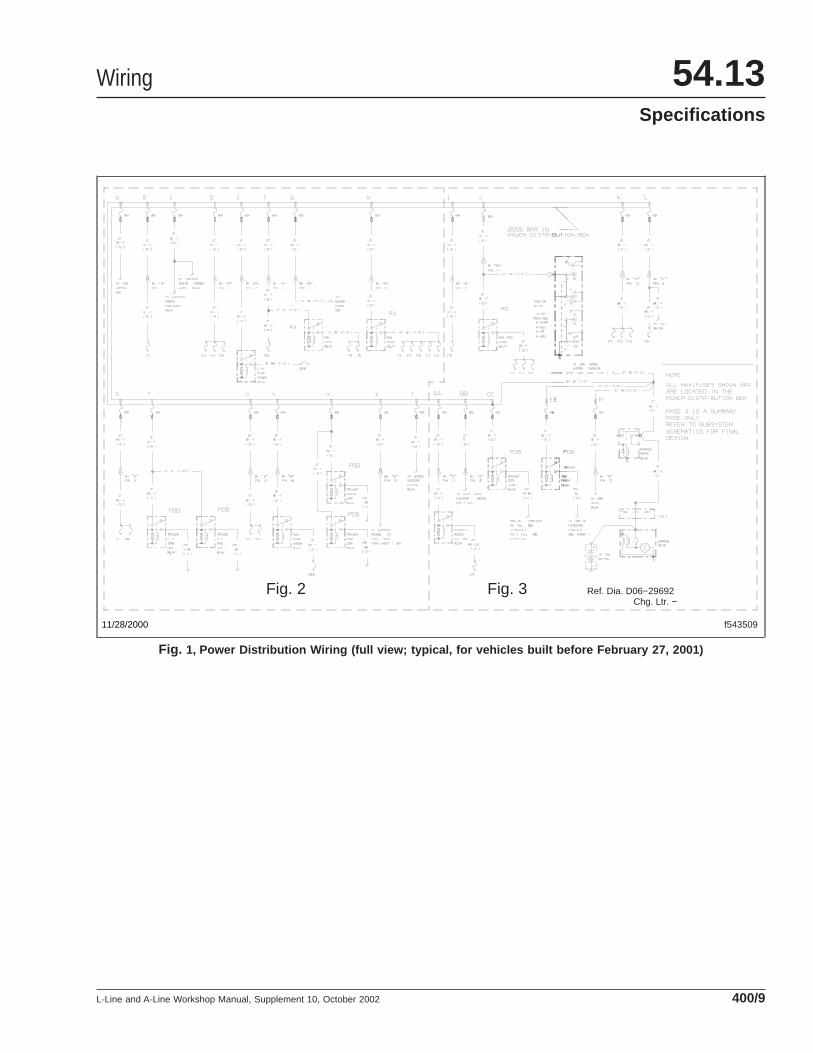
f543509
Ref. Dia. D06−29692 Chg. Ltr. −
Fig. 2 Fig. 3
11/28/2000
Fig. 1, Power Distribution Wiring (full view; typical, for vehicles built before February 27, 2001)
Wiring 54.13Specifications
L-Line and A-Line Workshop Manual, Supplement 10, October 2002 400/9
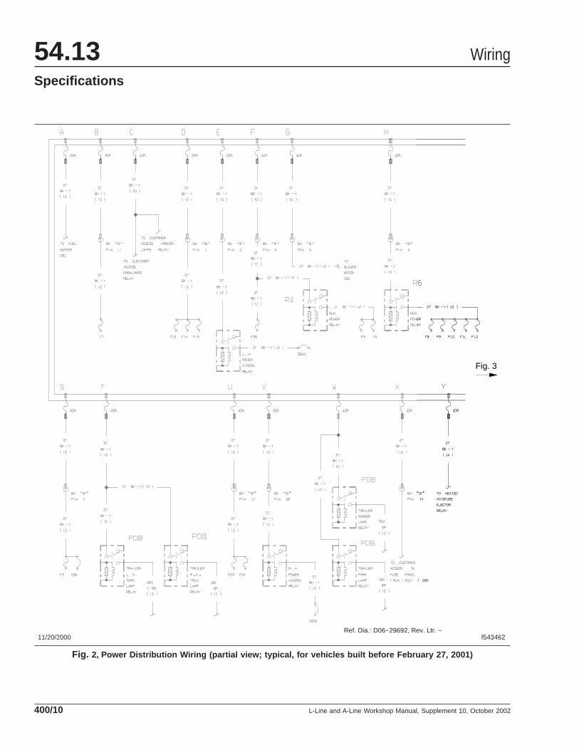
11/20/2000 f543462Ref. Dia.: D06−29692, Rev. Ltr. −
Fig. 3
Fig. 2, Power Distribution Wiring (partial view; typical, for vehicles built before February 27, 2001)
Wiring54.13Specifications
L-Line and A-Line Workshop Manual, Supplement 10, October 2002400/10
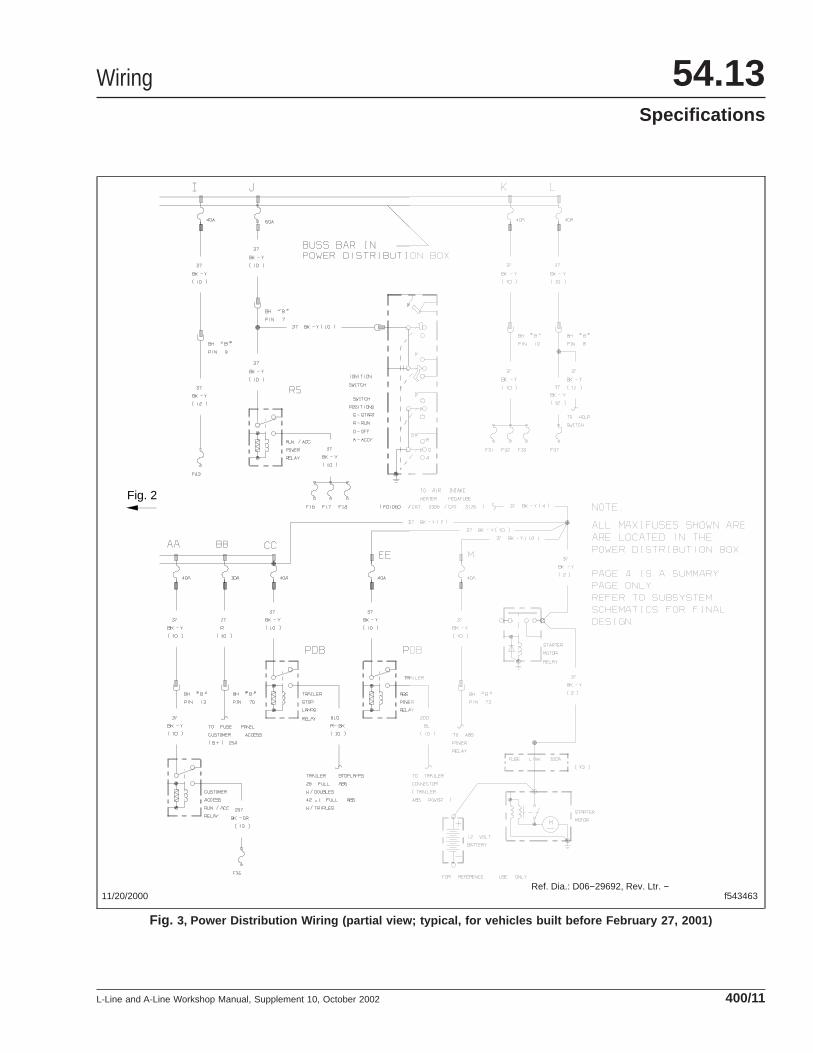
11/20/2000 f543463Ref. Dia.: D06−29692, Rev. Ltr. −
Fig. 2
Fig. 3, Power Distribution Wiring (partial view; typical, for vehicles built before February 27, 2001)
Wiring 54.13Specifications
L-Line and A-Line Workshop Manual, Supplement 10, October 2002 400/11
f543508
Ref. Dia. D06−29690 Chg. Ltr. −
Fig. 5 Fig. 6
11/28/2000
Fig. 4, Customer Access Circuits Wiring (full view; typical, for vehicles built before February 27, 2001)
Wiring54.13Specifications
L-Line and A-Line Workshop Manual, Supplement 10, October 2002400/12

11/21/2000 f543464
Ref. Dia. D06−29690 Chg. Ltr. −
Fig. 6
Fig. 5, Customer Access Circuits Wiring (partial view; typical, for vehicles built before February 27, 2001)
Wiring 54.13Specifications
L-Line and A-Line Workshop Manual, Supplement 10, October 2002 400/13
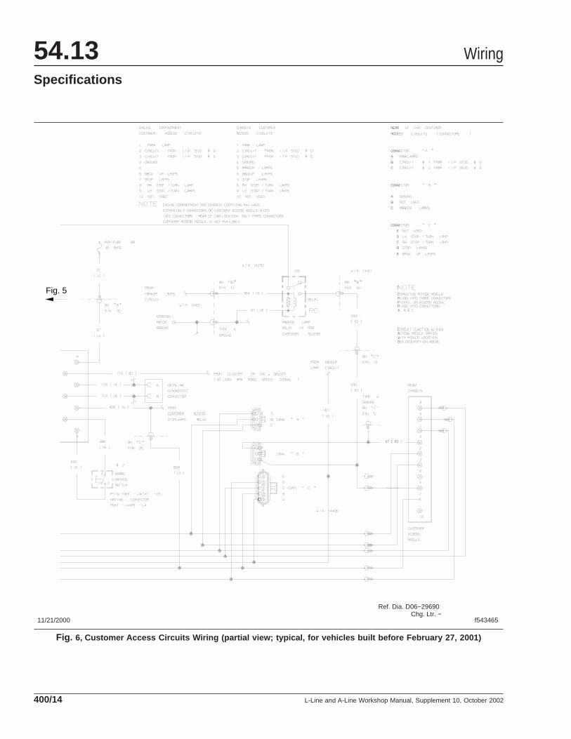
11/21/2000 f543465
Ref. Dia. D06−29690 Chg. Ltr. −
Fig. 5
Fig. 6, Customer Access Circuits Wiring (partial view; typical, for vehicles built before February 27, 2001)
Wiring54.13Specifications
L-Line and A-Line Workshop Manual, Supplement 10, October 2002400/14

11/21/2000 f543466
Ref. Dia. D06−29689 Chg. Ltr. −
Fig. 7, Instrument Panel Wiring (full view; typical, for vehicles built before February 27, 2001)
Wiring 54.13Specifications
L-Line and A-Line Workshop Manual, Supplement 10, October 2002 400/15
f543507
Ref. Dia. D06−29681 Chg. Ltr. −
Fig. 9
Fig. 10
11/28/2000
Fig. 8, Cab Ground Summary (full view; typical, for vehicles built before February 27, 2001)
Wiring54.13Specifications
L-Line and A-Line Workshop Manual, Supplement 10, October 2002400/16

11/21/2000 f543467
Ref. Dia. D06−29681 Chg. Ltr. −
Fig. 10
Fig. 9, Cab Ground Summary (partial view; typical, for vehicles built before February 27, 2001)
Wiring 54.13Specifications
L-Line and A-Line Workshop Manual, Supplement 10, October 2002 400/17
11/21/2000 f543468
Ref. Dia. D06−29681 Chg. Ltr. −
Fig. 9
Fig. 10, Cab Ground Summary (partial view; typical, for vehicles built before February 27, 2001)
Wiring54.13Specifications
L-Line and A-Line Workshop Manual, Supplement 10, October 2002400/18
11/21/2000 f543469
Ref. Dia. D06−29679 Chg. Ltr. −
Fig. 11, Right-Hand-Drive Chassis Ground Summary (full view; typical, for vehicles built before February 27,2001)
Wiring 54.13Specifications
L-Line and A-Line Workshop Manual, Supplement 10, October 2002 400/19

11/21/2000 f543483
Ref. Dia. D06−29680 Chg. Ltr. −
Fig. 12, Left-Hand-Drive Chassis Ground Summary (full view; typical, for vehicles built before February 27, 2001)
Wiring54.13Specifications
L-Line and A-Line Workshop Manual, Supplement 10, October 2002400/20

f54349311/21/2000
Fig. 13, Bulkhead Connector "A" Pin and CircuitNumber Identification (typical, for vehicles built before
February 27, 2001)
f54349411/21/2000
Fig. 14, Bulkhead Connector "B" Pin and CircuitNumber Identification (typical, for vehicles built before
February 27, 2001)
Wiring 54.13Specifications
L-Line and A-Line Workshop Manual, Supplement 10, October 2002 400/21

f54349511/21/2000
Fig. 15, Bulkhead Connector "C" Pin and CircuitNumber Identification (typical, for vehicles built before
February 27, 2001)
Wiring54.13Specifications
L-Line and A-Line Workshop Manual, Supplement 10, October 2002400/22