
Generac Power Systems, Inc. - Genset Services
44
Owner’s Manual 60 Hz Air-Cooled Generators 20 kW Synergy™ SAVE THIS MANUAL FOR FUTURE REFERENCE Para español , visita: http://www.generac.com/service-support/product-support-lookup Pour le français, visiter : http://www.generac.com/service-support/product-support-lookup Register your Generac product at: WWW.GENERAC.COM 1-888-GENERAC (888-436-3722) (000209a) WARNING This product is not intended to be used in a critical life support application. Failure to adhere to this warning could result in death or serious injury.
Transcript of Generac Power Systems, Inc. - Genset Services

Owner’s Manual60 Hz Air-Cooled Generators
20 kW Synergy™
SAVE THIS MANUAL FOR FUTURE REFERENCE
Para español , visita: http://www.generac.com/service-support/product-support-lookup
Pour le français, visiter : http://www.generac.com/service-support/product-support-lookup
000918
Register your Generac product at:WWW.GENERAC.COM
1-888-GENERAC(888-436-3722)
(000209a)
WARNINGThis product is not intended to be used in a critical life support application. Failure to adhere to this warning could result in death or serious injury.

ii Owner’s Manual for 60 Hz Air-cooled Generators
Use this page to record important information about your generator set.
Record the information found on your unit data label on thispage. For the location of the unit data label, see GeneralInformation. The unit has a label plate affixed to the insidepartition, to the left of the control panel console as shown inFigure 2-1. For directions on how to open the top lid andremove the front panel, see Operation.
When contacting an Independent Authorized Service Dealer(IASD) about parts and service, always supply the completemodel number and serial number of the unit.
Operation and Maintenance: Proper maintenance and careof the generator ensures a minimum number of problemsand keeps operating expenses at a minimum. It is theoperator’s responsibility to perform all safety checks, tomake sure that all maintenance for safe operation isperformed promptly. Generac recommends that theequipment be checked periodically by an IndependentAuthorized Service Dealer. Normal maintenance, serviceand replacement of parts are the responsibility of the owner/operator and, as such, are not considered defects inmaterials or workmanship within the terms of the warranty.Individual operating habits and usage may contribute to theneed for additional maintenance or service.
When the generator requires servicing or repairs, Generacrecommends contacting an Independent Authorized ServiceDealer for assistance. Authorized service technicians arefactory-trained and are capable of handling all serviceneeds.To locate the nearest Independent Authorized ServiceDealer, please visit the dealer locator at:
www.generac.com/Service/DealerLocator/
Model:
Serial:
Prod Date Week:
Volts:
LPV Amps:
NG Amps:
Hz:
Phase:
Controller P/N:
(000005)
WARNINGCalifornia Proposition 65. This product contains or emits chemicals known to the state of California to cause cancer, birth defects, and other reproductive harm.
(000004)
WARNINGCalifornia Proposition 65. Engine exhaust and some of its constituents are known to the state of California to cause cancer, birth defects, and other reproductiveharm.

Table of Contents
Section 1: Safety Rules
Introduction ..................................................................1Read This Manual Thoroughly ....................................1
How to Obtain Service .................................................1
Safety Rules .................................................................2General Hazards .........................................................2
Exhaust Hazards .........................................................3
Electrical Hazards .......................................................3
Fire Hazards ................................................................4
Explosion Hazards ......................................................4
Section 2: General Information
Synergy Operating Principle .......................................5Benefits .......................................................................5
Start Up .......................................................................5
Normal Running ..........................................................5
Small Load Changes ...................................................5
Large Load (Not Overload) ..........................................5
Overload ......................................................................5
Low Speed Exercise ....................................................5
Normal Exercise ..........................................................5
Automatic Voltage Regulator (AVR) Cooling Fans ......5
Protection Systems .....................................................7
Emissions .....................................................................7
Specifications ...............................................................8Generator ....................................................................8
Engine .........................................................................8
Fuel Requirements .......................................................9
Battery Requirements ..................................................9
Battery Charger ............................................................9
Engine Oil Requirements ............................................9
Replacement Parts .......................................................9
Accessories ................................................................10
Section 3: Operation
Site Prep Verification .................................................11
Side Compartment .....................................................11Main Circuit Breaker (Generator Disconnect) ............11
LED Indicator Lights ..................................................11
120V GFCI Outlet/15 Amp Breaker ...........................11
Generator Enclosure .................................................11
Control Panel Interface ..............................................13
Using the Auto/Off/Manual Interface ........................13
Interface Menu Displays ............................................13The LCD display ........................................................13
Menu System Navigation ..........................................13
Setting the Exercise Timer ........................................16
Battery Charger ..........................................................16
Manual Transfer Operation .......................................17Transfer to Generator Power Source ........................17
Transfer Back to Utility Power Source .......................17
Automatic Transfer Operation ..................................18
Automatic Sequence of Operation ...........................18Utility Failure ..............................................................18
Cranking ....................................................................18
Cold Smart Start ........................................................18
Load Transfer ............................................................18
Shutting Generator Down While Under Load ..........19To turn the generator OFF: .......................................19
To turn the generator back ON: .................................19
Section 4: Maintenance
Maintenance ...............................................................21
Performing Scheduled Maintenance ........................21
Before Servicing ........................................................21
Maintenance Kits .......................................................21
Service Schedule .......................................................22Maintenance Log .......................................................23
Oil, oil filter, air filter and spark plug replacement .....23
Valve Adjustment ......................................................23
Checking Engine Oil Level ........................................23Engine Oil Recommendations ...................................23
Changing the Oil and Oil Filter .................................24
Replacing the Engine Air Filter .................................25
Replacing the AVR Filter ...........................................25
Maintaining the Spark Plugs .....................................26
Valve Clearance Adjustment .....................................26Check Valve Clearance .............................................26
Adjust Valve Clearance .............................................27
Battery Maintenance ..................................................28
Attention After Submersion ......................................28
Corrosion Protection .................................................29
Remove From, and Return To Service Procedure ..29Remove From Service ...............................................29
Return to Service .......................................................29
Owner’s Manual for 60 Hz Synergy Generator™ iii

Section 2:
Section 5: Troubleshooting / Quick Reference Guide
General Troubleshooting .......................................... 31
Synergy Troubleshooting ......................................... 32
Load Shed Troubleshooting ..................................... 34
Quick Reference Guide ............................................. 36
iv Owner’s Manual for 60 Hz Synergy Generator™

Safety Rules
Section 1: Safety Rules
IntroductionThank you for purchasing this compact, highperformance, variable speed, air-cooled, engine-drivenstationary automatic standby generator. It is designed toautomatically supply electrical power to operate criticalloads during a utility power failure.
This unit is factory installed in an all-weather, metalenclosure that is intended exclusively for outdoorinstallation. This generator will operate using either vaporwithdrawn liquid propane (LP) or natural gas (NG).
NOTE: When sized properly, this generator is suitable forsupplying typical residential loads such as inductionmotors (sump pumps, refrigerators, air conditioners,furnaces, etc.), electronic components (computer,monitor, TV, etc.), lighting loads and microwaves.
Read This Manual Thoroughly
If any portion of this manual is not understood, contactthe nearest Independent Authorized Service Dealer forstarting, operating and servicing procedures.
This manual must be used in conjunction with theappropriate Owner’s Manual.
SAVE THESE INSTRUCTIONS: The manufacturersuggests that this manual and the rules for safe operationbe copied and posted near the unit installation site.Safety should be stressed to all operators and potentialoperators of this equipment.
Throughout this publication and on tags and decalsaffixed to the generator, DANGER, WARNING, andCAUTION blocks are used to alert personnel to specialinstructions about a particular operation that may behazardous if performed incorrectly or carelessly. Observethem carefully. Their definitions are as follows:
NOTE: Notes provide additional information important toa procedure or component.
These safety warnings cannot eliminate the hazards theyindicate. Observing safety precautions and strictcompliance with the special instructions while performingthe action or service are essential to preventing accidents.
The operator is responsible for proper and safe use ofthe equipment. The manufacturer strongly recommendsthat if the operator is also the owner, to read the Owner’sManual and thoroughly understand all instructions beforeusing this equipment. The manufacturer also stronglyrecommends instructing other users to properly start andoperate the unit. This prepares them if they need tooperate the equipment in an emergency.
How to Obtain Service
When the generator requires servicing or repairs, Generacrecommends contacting an Independent AuthorizedService Dealer (IASD) for assistance. Service techniciansare factory-trained and are capable of handling all serviceneeds. For assistance locating a dealer, go towww.generac.com/Service/DealerLocator/.
When contacting an IASD about parts and service,always supply the complete model number and serialnumber of the unit as given on its data decal, which islocated on the generator. Refer to Figure 2-1 for decallocation. Record the model number and serial numbers inthe spaces provided on the inside front cover of thismanual.
(000100a)
WARNINGConsult Manual. Read and understand manualcompletely before using product. Failure to completely understand manual and productcould result in death or serious injury.
(000001)
DANGERIndicates a hazardous situation which, if not avoided, will result in death or serious injury.
(000002)
WARNINGIndicates a hazardous situation which, if not avoided,could result in death or serious injury.
(000003)
CAUTIONIndicates a hazardous situation which, if not avoided,could result in minor or moderate injury.
Owner’s Manual for 60 Hz Synergy Generator™ 1

Safety Rules
Safety RulesStudy these SAFETY RULES carefully before installing,operating or servicing this equipment. Become familiarwith this Owner’s Manual and with the unit. Thegenerator can operate safely, efficiently and reliably onlyif it is properly installed, operated and maintained. Manyaccidents are caused by failing to follow simple andfundamental rules or precautions.
The manufacturer cannot anticipate every possiblecircumstance that might involve a hazard. The warnings inthis manual and on tags and decals affixed to the unit are,therefore, not all-inclusive. If using a procedure, workmethod, or operating technique the manufacturer does notspecifically recommend, verify that it is safe for others.Also, make sure the procedure, work method or operatingtechnique utilized does not render the generator unsafe.
General Hazards
(000190)
DANGERLoss of life. Property damage. Installation must alwayscomply with applicable codes, standards, laws and regulations. Failure to do so will result in death or serious injury.
Automatic start-up. Disconnect utility power and render unit inoperable before working on unit. Failure to do so will result in death or serious injury.
(000191)
DANGER
WARNINGThis unit is not intended for use as a prime power source. It is intended for use as an intermediate power supply in the event of temporary power outage only. See individual unit specifications for required maintenance and run times pertaining to use. (000247)
(000209a)
WARNINGThis product is not intended to be used in a critical life support application. Failure to adhere to this warning could result in death or serious injury.
(000187)
WARNING
(000130)
WARNINGAccidental Start-up. Disconnect the negative battery cable, then the positive battery cable when working on unit. Failure to do so could result in death or serious injury.
(000182)
WARNING
(000155)
WARNINGOnly a trained and licensed electrician should performwiring and connections to unit. Failure to follow properinstallation requirements could result in death, seriousinjury, and damage to equipment or property.
(000115)
WARNINGMoving Parts. Do not wear jewelry when starting or operating this product. Wearing jewelry while starting or operating this product could result in death or serious injury.
(000111)
WARNINGMoving Parts. Keep clothing, hair, and appendages away from moving parts. Failure to do so could result in death or serious injury.
(000108)
WARNINGHot Surfaces. When operating machine, do not touch hot surfaces. Keep machine away from combustibles during use. Hot surfaces could result in severe burns or fire.
(000146)
WARNINGEquipment and property damage. Do not alter construction of, installation, or block ventilation for generator. Failure to do so could result in unsafe operation or damage to the generator.
2 Owner’s Manual for 60 Hz Synergy Generator™

Safety Rules
Inspect the generator regularly, and contact the nearestIndependent Authorized Service Dealer for parts needingrepair or replacement.
Exhaust Hazards
• Adequate, unobstructed flow of cooling andventilating air is critical to correct generatoroperation. Do not alter the installation or permiteven partial blockage of ventilation provisions, asthis can seriously affect safe operation of thegenerator. The generator must be installed andoperated outdoors only.
Electrical HazardsWARNING
Risk of injury. Do not operate or service this machine if not fully alert. Fatigue can impair the ability to service this equipment and could result in death or serious injury. (000215)
WARNINGEnvironmental Hazard. Always recycle batteries at an official recycling center in accordance with all local laws and regulations. Failure to do so could result inenvironmental damage, death or serious injury.
(000228)
WARNINGInjury and equipment damage. Do not use generator as a step. Doing so could result in falling, damaged parts, unsafe equipment operation, and could result in death or serious injury. (000216)
Asphyxiation. Running engines produce carbon monoxide, a colorless, odorless, poisonous gas. Carbon monoxide, if not avoided, will result in death or serious injury.
(000103)
DANGER
(000178a)
Asphyxiation. Always use a battery operated carbon monoxide alarm indoors and installed according to the manufacturer’s instructions. Failure to do so could result in death or serious injury.
WARNING
(000144)
DANGERElectrocution. Contact with bare wires, terminals, and connections while generator is running will result in death or serious injury.
(000150)
DANGERElectrocution. Never connect this unit to the electricalsystem of any building unless a licensed electrician has installed an approved transfer switch. Failure to do so will result in death or serious injury.
(000131a)
DANGERElectrical backfeed. Use only approved switchgear to isolate generator when electrical utility is the primary power source. Failure to do so will result in death, serious injury, and equipment damage.
(000152)
DANGERElectrocution. Verify electrical system isproperly grounded before applying power.Failure to do so will result in death or seriousinjury.
(000188)
DANGERElectrocution. Do not wear jewelry while working on this equipment. Doing so will result in death or serious injury.
(000104)
DANGERElectrocution. Water contact with a power source, if not avoided, will result in death or serious injury.
(000144)
DANGERElectrocution. Contact with bare wires, terminals, and connections while generator is running will result in death or serious injury.
(000145)
DANGERElectrocution. In the event of electrical accident, immediately shut power OFF. Use non-conductive implements to free victim from live conductor. Apply first aid and get medical help. Failure to do so will result in death or serious injury.
Owner’s Manual for 60 Hz Synergy Generator™ 3

Safety Rules
Fire Hazards
Comply with regulations the Occupational Safety andHealth Administration (OSHA) has established. Also,verify that the generator is installed in accordance withthe manufacturer’s instructions and recommendations.Following proper installation, do nothing that might alter asafe installation and render the unit in noncompliancewith the aforementioned codes, standards, laws andregulations.
Explosion Hazards
WARNINGFire hazard. Do not obstruct cooling and
ventilating airflow around the generator. Inadequate ventilation could result in fire hazard, possible equipment damage, death or serious injury. (000217)
WARNINGFire and explosion. Installation must comply with all local, state, and national electrical
(000218)
building codes. Noncompliance could result in unsafe operation, equipment damage, death or serious injury.
WARNINGFire hazard. Use only fully-charged fire
(000219)
extinguishers rated “ABC” by the NFPA. Discharged or improperly rated fire extinguishers will not extinguish electrical fires in automatic standby generators.
(000100a)
WARNINGConsult Manual. Read and understand manualcompletely before using product. Failure to completely understand manual and productcould result in death or serious injury.
WARNING
required safety equipment could result in death or serious injury. (000221)
Risk of electrocution. Refer to NFPA 70E for safety equipment required when working with with a live electrical system. Failure to use
(000147)
WARNINGRisk of Fire. Unit must be positioned in amanner that prevents combustible materialaccumulation underneath. Failure to do socould result in death or serious injury.
(000192)
DANGER
(000151)
DANGERConnection of fuel source must be done by a qualifiedprofessional technician or contractor. Incorrect installationof this unit will result in death, serious injury, and damageto equipment and property damage.
(000174)
DANGERRisk of fire. Allow fuel spills to completely dry before starting engine. Failure to do so will result in death or serious injury.
(000110)
WARNINGRisk of Fire. Hot surfaces could ignite combustibles, resulting in fire. Fire could result in death or serious injury.
4 Owner’s Manual for 60 Hz Synergy Generator™

General Information
Section 2: General Information
Synergy Operating Principle
Benefits
The Synergy 20 kW generator brings exciting newtechnology to the Home Standby Generator. Thegenerator is significantly more fuel-efficient than constantspeed generators at normal loads, provides premiumpower quality, and is significantly quieter while operatingat exercise and normal loads.
• Exceptionally quiet exercise at 57 dB
• Quieter operation; 3 dB sound reduction with improved tonal qualities at exercise and under normal loads
• Cleanest Standby power available with 1.5 THD
• Significant fuel savings: more fuel efficient under normal loads
• Lower operating speed at 2700 rpm at low loads
• Tuned Helmhortz resonator and muffler to further reduce sound levels
• Variable Speed / Constant Frequency operation
Start Up
When the generator starts, the engine speed increases to3600 RPM to produce maximum power. This optimizespower to carry the load when the transfer switchoperates. The engine RPM then gradually decreases to aspeed appropriate for the attached load.
For example: If there is no load, the engine speeddecreases to approximately 2700 RPM. The time it takesto decrease to 2700 RPM is approximately 4–5 minutes.Since the rate of decrease is linear, less time would berequired for it to decrease to only 3400 RPM.
During startup, as the engine speed increases to 3600RPM, the Automatic Voltage Regulator (AVR) electronicsperform a self test (before transfer) involving an overallsystem check of the unit. If a fault is detected, the unitshuts down and displays an alarm.
Normal Running
The engine operates between 2700 RPM–3600 RPMdepending on the attached load. When the loadincreases or decreases, the speed increases ordecreases accordingly.
Small Load Changes
The system is designed to maintain the current enginespeed for small load changes. Larger load changes resultin a change in engine speed to appropriately handle theload.
Large Load (Not Overload)
The engine always runs at a speed appropriate for theattached load. When a large load is applied, the fastloadshed signal is activated. All loads attached to theloadshed controller in the transfer switch are droppedand the engine speed immediately increases to 3600RPM. Five seconds later, the loadshed signal isdeactivated and Loads 3 and 4 are sequenced back on,spaced 15 seconds apart. Loads 1 and 2, which aredesigned for air conditioners, are sequenced back onafter five minutes.
The engine speed remains at 3600 RPM for aprogrammable time (20 minutes default) and then slowsto the speed appropriate for the attached load. Theprogrammable time can be changed by the dealer toprevent annoying increases and decreases in enginespeed if large loads turn on and off frequently.
Overload
If a load is sensed that is too large for the engine, thatload will be locked out for a period of 30 minutes. If theload is not connected through a fast loadshed-enabledcontroller and module, the generator will shut down withan “Overload” alarm.
Low Speed Exercise
Low speed exercise operates at 1950 RPM for fiveminutes. The output voltage and frequency will not be atthe rated voltage and frequency during exercise.
Normal Exercise
Normal exercise is at 3600 RPM at normal voltage andfrequency levels for 5 minutes.
Automatic Voltage Regulator (AVR) Cooling Fans
The system is equipped with two fans to cool the AVRelectronics. The primary fan is powered by AC duringoperation. The secondary fan is powered by 12V DCthrough the controller. The fans are monitored duringoperation and, if a failure occurs, an alarm is displayed.
The secondary fan continues to operate for up to onehour after the generator is shut down (even if the 7.5amp ATO fuse is removed). Proper cooling must occurbefore removing battery connections for maintenance orother service activity. Be extremely careful when workingnear the AVR fan housing.
(000111)
WARNINGMoving Parts. Keep clothing, hair, and appendages away from moving parts. Failure to do so could result in death or serious injury.
Owner’s Manual for 60 Hz Synergy Generator™ 5

General Information
NOTE: The AVR cooling air inlet includes a filter. Verifythe filter is installed and properly seated at time the unit isinstalled. Check the filter at regular maintenance intervalsto verify proper airflow.
Figure 2-1. Component Locations
A. Automatic Voltage Regulator (AVR) H. Circuit Breakers
B. Oil Dipstick I. Fuel Inlet (Back)
C. Oil Fill Cap J. Fuel Regulator
D. Engine Air Filter K. Battery Compartment
E. AVR Air Filter L. Oil Filter
F. Data Label M. Composite Base
G. Control Pad N. Exhaust Enclosure
001402
A
B C D E F
J
KLM
N
G
H
I
6 Owner’s Manual for 60 Hz Synergy Generator™

General Information
Protection SystemsThe generator may have to run for long periods of timewith no operator present to monitor the engine/generatorconditions. Therefore, the generator is equipped with anumber of systems to automatically shut down the unit toprotect it against potentially damaging conditions. Someof these systems are as follows:
Alarms:
Warnings:
The control panel contains a display which alerts theoperator when a fault condition occurs. The above list isnot all inclusive. For more information about alarms andcontrol panel operation, see Operation.
NOTE: A warning will indicate a condition, on thegenerator, that should be addressed but not shut thegenerator down. An alarm will shut the generator down toprotect the system from any damage. In the event of analarm, an owner can clear the alarm and restart thegenerator prior to contacting an Independent AuthorizedService Dealer. If the intermittent issue occurs again,contact an Independent Authorized Service Dealer.
NOTE: For Synergy-specific alarms, see GeneralTroubleshooting.
EmissionsThe United States Environmental Protection Agency (USEPA) (and California Air Resources Board (CARB), forengines/equipment certified to California standards)requires that this engine/equipment complies withexhaust and evaporative emissions standards. Locatethe emissions compliance decal on the engine todetermine applicable standards. For emissions warrantyinformation, please reference the included emissionswarranty. It is important to follow the maintenancespecifications in the manual to ensure that the enginecomplies with the applicable emissions standards for theduration of the product’s life.
This generator is certified to operate on Liquid PropaneVapor fuel or pipeline Natural Gas.
The Emission Control System code is EM (EngineModification). The Emission Control System on thisgenerator may consist of the following components:
• High Temperature
• Low Oil Pressure
• Overcrank
• Overspeed
• Overvoltage
• Undervoltage
• Overload
• Underspeed
• RPM Sensor Loss
• Controller Fault
• Wiring Error
• Fuse Problem
• Stepper Overcurrent
• Charger Warning
• Charger Missing AC
• Low Battery
• Battery Problem
• Exercise Set Error
• USB Warning
• Download Failure
Air Induction System
• Intake Pipe / Manifold
• Air Cleaner
Ignition System
• Spark Plug
• Ignition Module
Fuel Metering System
• Carburetor / Mixer Assembly
• Fuel Regulator
Exhaust System
• Exhaust Manifold
• Muffler
Owner’s Manual for 60 Hz Synergy Generator™ 7
General Information
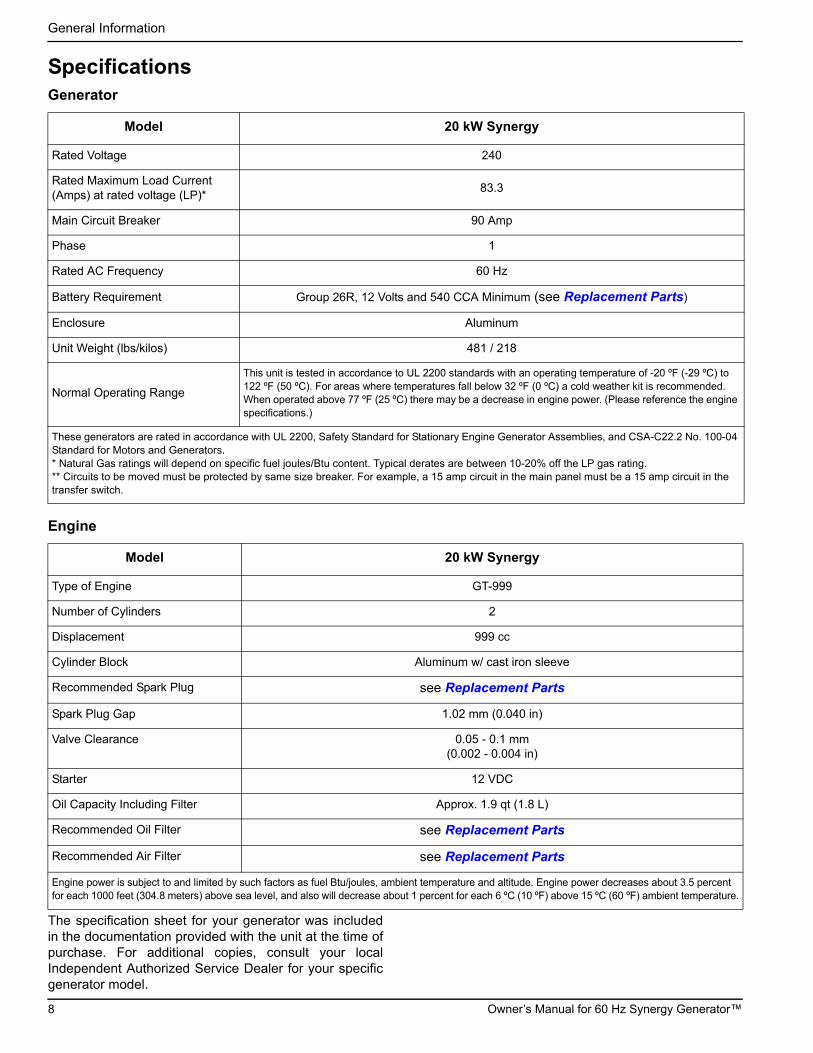
SpecificationsGenerator
Engine
The specification sheet for your generator was includedin the documentation provided with the unit at the time ofpurchase. For additional copies, consult your localIndependent Authorized Service Dealer for your specificgenerator model.
Model 20 kW Synergy
Rated Voltage 240
Rated Maximum Load Current (Amps) at rated voltage (LP)*
83.3
Main Circuit Breaker 90 Amp
Phase 1
Rated AC Frequency 60 Hz
Battery Requirement Group 26R, 12 Volts and 540 CCA Minimum (see Replacement Parts)
Enclosure Aluminum
Unit Weight (lbs/kilos) 481 / 218
Normal Operating Range
This unit is tested in accordance to UL 2200 standards with an operating temperature of -20 ºF (-29 ºC) to 122 ºF (50 ºC). For areas where temperatures fall below 32 ºF (0 ºC) a cold weather kit is recommended. When operated above 77 ºF (25 ºC) there may be a decrease in engine power. (Please reference the engine specifications.)
These generators are rated in accordance with UL 2200, Safety Standard for Stationary Engine Generator Assemblies, and CSA-C22.2 No. 100-04 Standard for Motors and Generators.* Natural Gas ratings will depend on specific fuel joules/Btu content. Typical derates are between 10-20% off the LP gas rating.** Circuits to be moved must be protected by same size breaker. For example, a 15 amp circuit in the main panel must be a 15 amp circuit in the transfer switch.
Model 20 kW Synergy
Type of Engine GT-999
Number of Cylinders 2
Displacement 999 cc
Cylinder Block Aluminum w/ cast iron sleeve
Recommended Spark Plug see Replacement Parts
Spark Plug Gap 1.02 mm (0.040 in)
Valve Clearance 0.05 - 0.1 mm(0.002 - 0.004 in)
Starter 12 VDC
Oil Capacity Including Filter Approx. 1.9 qt (1.8 L)
Recommended Oil Filter see Replacement Parts
Recommended Air Filter see Replacement Parts
Engine power is subject to and limited by such factors as fuel Btu/joules, ambient temperature and altitude. Engine power decreases about 3.5 percent for each 1000 feet (304.8 meters) above sea level, and also will decrease about 1 percent for each 6 ºC (10 ºF) above 15 ºC (60 ºF) ambient temperature.
8 Owner’s Manual for 60 Hz Synergy Generator™

General Information
Fuel Requirements
The engine has been fitted with a dual fuel carburetionsystem. The unit will run on natural gas or LP gas(vapor), but it has been factory set to run on natural gas.The fuel system will be configured for the available fuelsource during installation.
Recommended fuels should have a BTU content of atleast 1000 Btus per cubic foot (37.26 megajoules percubic meter) for natural gas, or at least 2500 BTUs percubic foot (93.15 megajoules per cubic meter) for LP gas(vapor).
NOTE: If converting to LP gas from natural gas, aminimum LP tank size of 250 gallons (946 liters) isrecommended. See the Installation Manual for completeprocedures and details.
Battery RequirementsGroup 26R, 12V, minimum 540 CCA.
For proper battery maintenance procedures, see Section4 Maintenance.
Battery ChargerThe battery charger is integrated into the control panelmodule in all models. It operates as a Smart Chargerwhich ensures output charging levels are safe andcontinuously optimized to promote maximum battery life.
Engine Oil RequirementsFor proper oil viscosity, see chart in Figure 4-1.
Replacement Parts
(000105)
DANGERExplosion and Fire. Fuel and vapors are extremely flammable and explosive. Add fuel in a well ventilated area. Keep fire and spark away. Failure to do so will result in death or serious injury.
Description 20 kW Synergy
26R Exide Battery 0H3421S
Spark Plug 0G0767A
Oil Filter 070185E
Air Filter 0J8478
Control Panel Fuse 0D7178T
Transfer Switch Fuses 073590A
Owner’s Manual for 60 Hz Synergy Generator™ 9

General Information
AccessoriesPerformance enhancing accessories are available for air-cooled generators.
NOTE: Contact an Independent Authorized Service Dealer or visit www.generac.com for additional information onreplacement parts, accessories, and extended warranties.
Accessory Description
Cold Weather Kit Recommended in areas where temperatures fall below 32 ºF (0 ºC).
Scheduled Maintenance Kit Includes all pieces necessary to perform maintenance on the generator along with oil recommendations.
Auxiliary Transfer Switch Lockout Enables any of the transfer switches to completely lock out one large electrical load by tying into its control system.
Fascia Base Wrap The fascia base wrap snaps together around the bottom of new air-cooled generators. This offers a sleek, contoured appearance as well as offering protection from rodents and insects by covering the lifting holes located in the base. Requires use of the mounting pad shipped with the generator.
Mobile Link™ (USA only) Provides a personalized web portal that displays the generator status, maintenance schedule, event history and much more. This portal is accessible via computer, tablet or smart phone. Sends emails and/or text notifications the moment there is any change in the generator’s status. Notification settings can be customized to what type of alert is sent and how often. For more information, visit www.MobileLinkGen.com.
Touch-Up Paint Kit Very important to maintain the look and integrity of the generator enclosure. This kit includes touch-up paint and instructions.
Wireless Local Monitor Completely wireless and battery powered, the Wireless Local Monitor provides you with instant status without ever leaving the house. Status lights (red, yellow and green) alert owners when the generator needs attention. Magnetic backing permits refrigerator mounting and gives a 600 foot line of sight communication.
Power Management Module (PMM)Starter Kit
Includes one module with transformer. The transformer, which is mounted inside theATS enclosure, interfaces with the OPCB to generate the 24 VAV signal needed forcontrol of the contactor (Load 1 on the OPCB).
Power Management Module (PMM) Includes one module only. To achieve full system functionality, a total of three kits arerequired to allow control of the three remaining contactors (Loads 2/3/4 on the OPCB).
Extended Warranty Coverage Extend your generator warranty coverage by purchasing extended warranty coverage. Covers both parts and labor. Extended coverage can be purchased within 12 months of the end-users purchase date.This extended coverage is applicable to registered units and end-user proof of purchase must be available upon request.
Available for Generac®, Guardian®, Centurion®, and Synergy™ products. Not available for EcoGen™ products or all international purchases.
10 Owner’s Manual for 60 Hz Synergy Generator™

Operation
Section 3: Operation
Site Prep Verification It is important that the generator is installed in such a waythat the airflow into and out of the generator is notimpeded. Verify that all shrubs or tall grasses have beenremoved within 3 ft. (0.91 m) of the intake and dischargelouvers on the sides of the enclosure. It is also importantthat the generator is not subject to water intrusion. Verifythat all potential sources such as water sprinklers, roofrun-off, rain gutter down spouts and sump pumpdischarges are directed away from the generatorenclosure.
Turn the generator OFF before performing maintenance.Remove 7.5 Amp fuse, T1 and T2 battery charge fuses,and disconnect battery cables to prevent accidental startup. Disconnect the NEGATIVE (-) cable first, thendisconnect the POSITIVE (+) cable. When connectingthe cables, connect the POSITIVE cable first, theNEGATIVE cable last.
Side CompartmentLocal codes may require that the side compartment belocked. A hasp is provided so the owner/operator cansecure the side compartment with a padlock. Check localcodes for side compartment locking requirements.
Figure 3-1. Open Side Compartment
Main Circuit Breaker (Generator Disconnect)
This is a 2-pole breaker rated according to relevantspecifications. See “A” in Figure 3-1.
LED Indicator Lights
See “B” in Figure 3-1.
• Green LED “Ready” light is on when utility ispresent and the control panel button is in the AUTOposition. This also indicates when the generator isrunning.
• Red LED “Alarm” light is on when the generator isOFF or a fault is detected. Contact an IndependentAuthorized Servicing Dealer.
• Yellow LED “Maintenance” light.
NOTE: Yellow LED may be on at the same time as eitherthe Red or Green LED.
120V GFCI Outlet/15 Amp BreakerSee “C” in Figure 3-1. This generator is equipped with anexternal 15 Amp, 120 volt GFCI convenience outletlocated in the top corner of the compartment.
When the generator is running in the absence of utilitypower, this outlet may also be used to power itemsoutside the home such as lights or power tools. Thisoutlet may also be used when utility power is present byrunning the generator in manual mode.
This outlet does not provide power if the generator is notrunning. Do not use this outlet when the generator is inExercise mode. This outlet is protected by a 15 Ampcircuit breaker in the side compartment.
Risk of fire. Keep air inlet and exhaust areasWARNING
(000251)
free from leaves, grass, snow and other debris. Failure to do so could result in death, serious injury, property, and equipment damage.
Automatic start-up. Disconnect utility power and render unit inoperable before working on unit. Failure to do so will result in death or serious injury.
(000191)
DANGER
(000182)
WARNING
000931
A
B
C
Owner’s Manual for 60 Hz Synergy Generator™ 11

Operation
Generator EnclosureThe lid is locked for shipping and remains locked whilethe generator is in normal operation. A set of keys isattached to the circuit breaker box door with a cable tie.
1. Cut the cable tie to remove the keys.
2. Use the keys to open the lid of the generator.
NOTE: The enclosed keys provided with this unit areintended for service personnel use only.
Figure 3-2. Circuit Breaker Box and Keys (As Shipped)
3. There are two locks securing the lid, one on each side (A in Figure 3-3). To properly open the lid, press down, on the lid, above the side lock and unlock the latch.
4. Repeat for the other side. If pressure is not applied from the top, the lid may appear stuck.
NOTE: Always verify that the side locks are unlockedbefore attempting to lift the lid.
5. Once the lid is open, remove the front access panel by lifting it up and out.
NOTE: Always the lift the front access panel up beforepulling away from enclosure (B and C in Figure 3-3). Donot pull the panel away from the enclosure before liftingup (D in Figure 3-3).
Figure 3-3. Side Lock Location and Front Panel Removal
000932
000597
A
A
001028
B DC
12 Owner’s Manual for 60 Hz Synergy Generator™
Operation
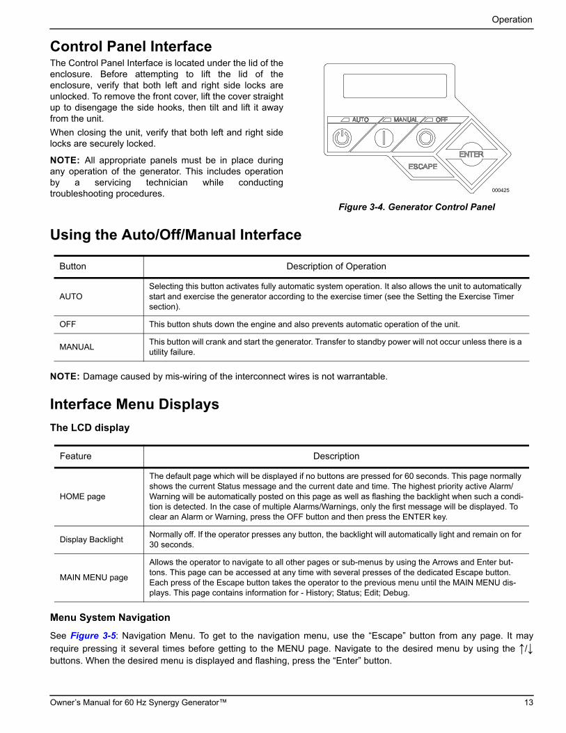
Control Panel InterfaceThe Control Panel Interface is located under the lid of theenclosure. Before attempting to lift the lid of theenclosure, verify that both left and right side locks areunlocked. To remove the front cover, lift the cover straightup to disengage the side hooks, then tilt and lift it awayfrom the unit.
When closing the unit, verify that both left and right sidelocks are securely locked.
NOTE: All appropriate panels must be in place duringany operation of the generator. This includes operationby a servicing technician while conductingtroubleshooting procedures.
Figure 3-4. Generator Control Panel
Using the Auto/Off/Manual Interface
NOTE: Damage caused by mis-wiring of the interconnect wires is not warrantable.
Interface Menu Displays
The LCD display
Menu System Navigation
See Figure 3-5: Navigation Menu. To get to the navigation menu, use the “Escape” button from any page. It may
require pressing it several times before getting to the MENU page. Navigate to the desired menu by using the ↑/↓buttons. When the desired menu is displayed and flashing, press the “Enter” button.
000425
Button Description of Operation
AUTOSelecting this button activates fully automatic system operation. It also allows the unit to automatically start and exercise the generator according to the exercise timer (see the Setting the Exercise Timer section).
OFF This button shuts down the engine and also prevents automatic operation of the unit.
MANUALThis button will crank and start the generator. Transfer to standby power will not occur unless there is a utility failure.
Feature Description
HOME page
The default page which will be displayed if no buttons are pressed for 60 seconds. This page normally shows the current Status message and the current date and time. The highest priority active Alarm/Warning will be automatically posted on this page as well as flashing the backlight when such a condi-tion is detected. In the case of multiple Alarms/Warnings, only the first message will be displayed. To clear an Alarm or Warning, press the OFF button and then press the ENTER key.
Display BacklightNormally off. If the operator presses any button, the backlight will automatically light and remain on for 30 seconds.
MAIN MENU page
Allows the operator to navigate to all other pages or sub-menus by using the Arrows and Enter but-tons. This page can be accessed at any time with several presses of the dedicated Escape button. Each press of the Escape button takes the operator to the previous menu until the MAIN MENU dis-plays. This page contains information for - History; Status; Edit; Debug.
Owner’s Manual for 60 Hz Synergy Generator™ 13

Operation
Figure 3-5. Navigation Menu
SYNERGY HSB MENU MAP
“Run Log”ESC
ENTER
ENTER
SYSTEM
BATTERY
HISTORY
EDIT
Exercise Time
14:00 Wednesday
Firmware Update
Press Enter
ESC
Current Date/Time
2/12/13 12:22
ESC
ENTER
ENTER
ESC
ESC
ESC
ESC
ENTER
ENTER
ESC
ESC
ENTER
ENTER
ESC
ENTER
ENTERENTER
ENTER
ENTER
ENTER
ENTER
ESC
ESC
Switched to “OFF”Hours of Protection
0 (H)
Language
English
Fuel Selection
NG or LP
Firmware Update
Insert USB
“Alarm Log”- Alarm Log +
- Run Log +- 1 thru 50 +
- 1 thru 50 +
Running ManualRunning-Utility Lost
Running-Remote StartRunning-2 Wire StartRunning - Exercise
Switched OffStopped - AutoStopped - Alarm
ESC
Select Min (0-59)
- 0 +
ESC
ESC
Select Hour (0-23)
- 14 +
ESC ESC
Quiet Test Mode ?
- YES or NO +
Select Frequency
- WEEKLY +- BIWEEKLY +- MONTHLY +
Quiet Test Mode only on certain models
Language
+ English -
Fuel Selection
+ NG or LP -
ENTERCold Smart Start?
YES or NO
ESCCold Smart Start?
- YES or NO +
Language
+ Espanol -+
-
+
-
Battery Condition
“Good” “Inspect Battery” or “Check Battery”
*“Fuse Problem” on Firmware 1.11 and older
ONLY
Note: Menu functions and features may vary dependingon unit model and firmware revision.
001594a
Warning Message(s)"Low Battery"
"Exercise Set Error""FIRMWARE ERROR-9"
"Fuel Pressure""Battery Problem""Charger Warning"
"Charger Missing AC""Overload Warning"
"Overload Cooldown""SEEPROM ABUSE"
"USB Warning""Download Failure"
Alarm Message(s)"High Engine Temp.""Low Oil Pressure"
"Overcrank""Overspeed"
"RPM Sense Loss""Underspeed""Internal Fault"
"FIRMWARE ERROR-7""WIRING ERROR"
"Over Voltage""Under Voltage"
"Overload Remove Load""Low Volts Remove Load"
"Stepper Over Current""Fuse Problem"
14 Owner’s Manual for 60 Hz Synergy Generator™

Operation
Figure 3-6. Navigation Menu
UP ARROW = +
DOWN ARROW = -
ESC
DATE/TIME
SUB MENUS
MAINT
DEALER
EXAMPLE: Inspect Battery 200 RnHr or 12/27/13
andNext Maintenance 200 RnHr or 12/27/13
Current Date/Time
02/14/16 07:40
ESC
ESC
ENTER
ENTER ESC ENTER
ESC ESC ESC
ENTER
ENTER
ESCMAINT:
Maint. Log
Run Hrs
Scheduled
ENTER
ENTER
Select Month (1-12)
- 2 +
Run Hours (H)
0.0
Select Date (1-31)
- 13 +ENTER
Select Year (0-99)
- 13 +ENTER
ENTER
Access Requires Password
Possible Message(s)Corrupted File
Invalid FileFile Not Found
Unsupported Device
"Current: VV XXXX "
"USB: VV XXXX"
"Are You Sure?"
"- Yes or No +"ESC
ENTER
ESCENTERESCENTER
Select “Yes” then Press “Enter” to continue or Press “ESCAPE” to escape out of updating.
During update process the Blue “Manual” light flashes, then the Green “Auto” light flashes. Sequence does this twice. When update is complete the unit returns to Install Wizard menu.
When the controller powers up the very first screen displays the version number for a few seconds.
When update is complete remove Thumb Drive, then follow the Install Wizard Menu.
- 1 thru 50 +"Battery Maintained"
"Schedule A Serviced""Schedule B Serviced""Maintenance Reset"
"Inspect Battery""Service Schedule A""Service Schedule B"
ESC
Select Min (0-59)
- 0 +
ESC
Select Hour (0-23)
- 14 +
Language
+ Francais -
Language
+ Portuguese -+
-
+
Select Day
- Wednesday +
001594b
+
-
Owner’s Manual for 60 Hz Synergy Generator™ 15

Operation
Setting the Exercise TimerThis generator is equipped with a configurable exercisetimer. There are two settings for the exercise timer.
Day/Time: Once set, the generator will start and exerciseat a predetermined day and time. During this exerciseperiod, the unit runs for approximately 5 or 12 minutes,depending on the model, and then shuts down.
Exercise frequency (how often the exercise will takeplace): Exercise frequency can be set to Weekly,Biweekly or Monthly. If Monthly is selected, the day of themonth must be selected from 1–28. The generator willexercise on that day each month. Transfer of loads to thegenerator output does not occur during the exercisecycle unless utility power is lost.
NOTE: If the installer tests the generator prior toinstallation, press the “enter” button to skip setting up theexercise timer.
NOTE: The exercise feature will operate only when thegenerator is placed in the AUTO mode and will not workunless this procedure is performed. The current date/timewill need to be reset every time the 12 volt battery isdisconnected and then reconnected, and/or when thefuse is removed.
Table 3-1 details the exercise information andprogramming options for all Home Standby generators.Figure 3-7 shows the engine speed profile during atypical low speed exercise cycle. While providing thenecessary periodic exercise operation, the lower rpmalso reduces fuel consumption, engine wear and noise.
Figure 3-7. Low Speed Exercise Profile
Battery ChargerNOTE: The battery charger is integrated into the controlmodule in all models.
The battery charger operates as a Smart Charger thatensures:
• Output is continually optimized to promotemaximum battery life.
• Charging levels are safe.
NOTE: A warning is displayed on the LCD when thebattery needs service.
Table 3-1. Generator Exercise Characteristics
Generator Size 20 kW Synergy
Low Speed Exercise 1950 rpm
Exercise Frequency Options Weekly/Bi-Weekly/Monthly
Exercise Time Length 5 minutes
2600
2800
3000
3200
3400
3600
3800
1800
2000
2200
2400
0 sec 5 s 10 15 20 25 30 35 40 45 1min 5 min
001403
Exe
rcis
e S
peed
(RP
M)
Exercise Time
16 Owner’s Manual for 60 Hz Synergy Generator™

Operation
Manual Transfer Operation
Prior to automatic operation, manually exercise thetransfer switch to verify that there is no interference withproper operation of the mechanism. Manual operation ofthe transfer switch is required if electronic operationshould fail.
Transfer to Generator Power Source
1. Verify generator is in the OFF mode.
2. Set the main circuit breaker (Generator Disconnect) to OFF or OPEN.
3. Turn off the utility power supply to the transfer switch using the means provided (such as a utility main line circuit breaker).
4. Use the manual transfer handle (A in Figure 3-8) inside the transfer switch to move the main contacts to the STANDBY position (loads connected to the standby power source).
5. To crank and start the engine, press the control panel MANUAL button.
6. Allow the engine to stabilize and warm up for a fewminutes.
7. Set the main circuit breaker (Generator Disconnect) to ON or CLOSED. The standby power source now powers the loads.
Figure 3-8. Manual Transfer Switch Operation
Transfer Back to Utility Power Source
When utility power has been restored, transfer back toutility source and shut down the generator. To manuallytransfer back to utility power and shut down thegenerator:
1. Set the Main Circuit Breaker (GeneratorDisconnect) to OFF or OPEN.
2. Allow the engine to run for two minutes at no-load to stabilize the internal temperatures.
3. Press the control panel OFF button. The engine should shut down.
4. Verify that utility power supply to the transfer switch is turned OFF.
(000132)
DANGERElectrocution. Do not manually transfer under load.Disconnect transfer switch from all power sources prior to manual transfer. Failure to do so will resultin death or serious injury, and equipment damage.
000228
A
B
MANUAL
• Will not transfer to generator if utility is present.
• Will transfer to generator if utility fails (below 65% of nominal for five consecutive seconds).
• Will transfer back when utility returns for 15 consecutive seconds. The engine will continue to
run until removed from the MANUAL mode.
AUTO
• Will start and run if utility fails for five consecutive seconds. (factory default)
• Will start a 5 second engine warm-up timer (or 30 seconds; refer to Cold Smart Start):
–Will not transfer if utility subsequently returns.
–Will transfer to generator if utility is not present.
• Will transfer back to utility once utility returns (above 80% of nominal) for 15 seconds.
• Will not transfer back to utility unless utility returns. The generator will shut down if the OFF
button is pressed or a shutdown alarm is present.
• Once utility power is returned, the generator will shut down after 1 minute cool-down time.
EXERCISE
• Will not exercise if generator is already running in either AUTO or MANUAL mode.
• During exercise, the controller will only transfer if utility fails during exercise for 10 seconds
(or 30 seconds; refer to Cold Smart Start) and will switch to AUTO.
Owner’s Manual for 60 Hz Synergy Generator™ 17

Operation
5. Use the manual transfer handle (A in Figure 3-8) inside the transfer switch to move the main contacts back to the UTILITY position (loads connected to the utility power source).
6. Turn on the utility power supply to the transfer switch using the means provided.
7. Press the control panel AUTO button.
Automatic Transfer OperationTo select automatic operation:
1. Make sure the transfer switch main contacts areset to the UTILITY position (loads connected to theutility power source).
2. Be sure that normal UTILITY power source voltage is available to transfer switch terminal lugs N1 and N2.
3. Press the AUTO button on the control panel interface.
4. Set the main circuit breaker (Generator Disconnect) to the ON (Closed) position.
With these steps complete, the generator will startautomatically when utility source voltage drops below apreset level. After the unit starts, loads are transferred tothe standby power source.
Automatic Sequence of Operation
Utility Failure
With the generator set to AUTO, when utility fails (below65% of nominal) a 5 second (dealer programmable) lineinterrupt delay time is started. If utility is still gone whenthe timer expires, the engine will crank and start. Oncestarted, a five second engine warm-up timer will beinitiated (or a 30 second warm-up timer; refer to ColdSmart Start). When the warm-up time expires, thecontroller will transfer the load to the generator. If theutility power is restored (above 80% nominal) at any timefrom the initiation of the engine start until the generator isready to accept load (5 second warm-up time has notelapsed), the controller will complete the start cycle andrun the generator through its normal cool down cycle,however, the load will remain on the utility source.
Cranking
The system will control the cyclic cranking as follows:
• Five cranking cycles as follows: 16 second crank,seven (7) second rest, 16 second crank, seven (7)second rest, followed by three (3) additional cyclesof seven (7) second cranks followed by seven (7)second rests.
Cold Smart Start
The Cold Smart Start feature can be enabled in the EDITmenu. With Cold Smart Start enabled, the generator willmonitor ambient temperature and the warm-up delay willbe adjusted based on prevailing conditions.
On a startup in AUTO mode, if the ambient temperatureis below a fixed temperature (based on model) thegenerator will warm up for 30 seconds. This allows theengine to warm before a load is applied. If the ambienttemperature is at or above the fixed temperature, thegenerator will startup with the normal warm-up delay offive seconds.
When the generator engine is started, a check for properoutput voltage build up will be performed.
If some condition impedes normal voltage creation, suchas frost crystals, dust, or dirt preventing a good electricalconnection, the start sequence will be interrupted so thata cleaning cycle of the internal electrical connections canbe attempted.
The cleaning cycle is an extended “Warming Up” periodwhich lasts for several minutes while the normalgenerator voltage output is determined to be low. Duringthis cycle, the generator controller will display the“Warming Up” on the display screen.
If the cleaning cycle fails to clear the obstruction, thegenerator controller display will show the “Under Voltage”message.
After several minutes, the alarm message can becleared, and a restart of the generator attempted.
If the problem persists, make no further attempts to start.Contact an Independent Authorized Service Dealer.
Load Transfer
The transfer of load when the generator is running isdependent upon the operating mode:
18 Owner’s Manual for 60 Hz Synergy Generator™

Operation
Shutting Generator Down While Under LoadIMPORTANT NOTE: To turn the generator off during utility outages to perform maintenance, or conserve fuel, follow these steps:
To turn the generator OFF (while running in AUTO and online):
1. Turn the main utility disconnect OFF.
2. Turn the main line circuit breaker (MLCB) on the generator to OFF (OPEN).
3. Turn the generator OFF.
To turn the generator back ON:
1. Put the generator back into AUTO and allow tostart and warm-up for a few minutes.
2. Set the MLCB on the generator to ON.
The system will now be operating in automatic mode.The main utility disconnect can be turned ON (CLOSED).To shut the unit OFF, this complete process must berepeated.
Owner’s Manual for 60 Hz Synergy Generator™ 19

Operation
This page intentionally left blank.
20 Owner’s Manual for 60 Hz Synergy Generator™

Maintenance
Section 4: Maintenance
MaintenanceRegular maintenance will improve performance andextend engine/equipment life. Generac Power Systems,Inc. recommends that all maintenance work beperformed by an Independent Authorized Service Dealer(IASD). Regular maintenance, replacement or repair ofthe emissions control devices and systems may beperformed by any repair shop or person of the owner’schoosing. However, to obtain emissions control warrantyservice free of charge, the work must be performed by anIASD. See the emissions warranty.
Performing Scheduled MaintenanceIt is important to perform maintenance as specified in theService Schedule for proper generator operation and toensure that the generator complies with the applicableemission standards for the duration of its useful life.Service and repairs may be performed by any qualifiedservice person or repair shop.
Engine oil and filter must be changed and valveclearance adjusted after the first 25 hours of operation.
Additionally, emissions critical maintenance must beperformed as scheduled in order for the EmissionsWarranty to be valid. Emissions-critical maintenanceconsists of servicing the air filter and spark plugs inaccordance with the Service Schedule.
The controller will prompt for Schedule A or Schedule Bmaintenance to be performed. Schedule A maintenanceconsists of the oil, oil filter and tune-up. Schedule Bmaintenance includes the oil, oil filter, tune-up, aircleaner, spark plug(s) and valve clearance.
NOTE: Since most maintenance alerts will occur at thesame time (most have two year intervals), only one willappear on the control panel display at any one time.Once the first alert is cleared, the next active alert will bedisplayed.
Before Servicing
If utility is present, the secondary 12V DC fan continuesto operate for up to one hour after the generator is shutdown, even if the 7.5 Amp ATO fuse is removed. Avoidthe AVR fan housing until fan rotation stops.
Follow the steps below prior to inspecting, maintaining, orservicing this unit:
1. Allow the generator to cool thoroughly beforeremoving battery connections for maintenance orother service.
2. Unlock left and right side locks. Open lid.
NOTE: For best results, press down on lid directlyabove each side lock, and while holding the liddown, use key to unlock latches.
3. Press OFF on the control pad. A red LEDilluminates to confirm that the system is in the OFFmode.
4. Move the Generator Disconnect Circuit Breakerswitch to the OFF (Open) position.
5. Pull up rubber flap covering fuse holder andremove 7.5 Amp fuse.
6. Remove T1 fuse from transfer switch.
Maintenance KitsTo maintain the product warranty, the engine oil shouldbe serviced in accordance with the recommendations ofthis manual. For your convenience, GeneracMaintenance Kits are available that include engine oil, oilfilter, air filter, spark plug(s), a shop towel and funnel.These kits can be obtained from an IndependentAuthorized Service Dealer (IASD).
To purchase on-line, access the maintenance kits pagethrough www.generac.com. Follow the prompts to enterdelivery information and complete the purchase.
All Generac oil kits meet minimum American PetroleumInstitute (API) Service Class SJ, SL, or better. Use nospecial additives. Select the appropriate viscosity oilgrade according to the expected operating temperature.Synthetic oil also can be used in the appropriate weightas standard.
(000182)
WARNING
(000222)
WARNINGMoving Parts. Avoid AVR fan housing for onehour after generator shutdown. Fan operates even if fuse is removed. Rotating fan bladescould result in death or serious injury.
Owner’s Manual for 60 Hz Synergy Generator™ 21

Maintenance
Service Schedule
NOTE: Contact an Independent Authorized Service Dealer or visit www.generac.com for additional information onreplacement parts.
Table 4-1. Service Maintenance Schedule
Service
Daily If Running Continuously
or
Before Each Use
Every
Year
Schedule AEvery Two
Years or 200 Hours
Schedule BEvery Four
Years or 400 Hours
Every 1000 hours
Check Enclosure Louvers for Dirt and Debris *
●
Check Lines and Connections for Fuel or Oil Leaks
●
Check Engine Oil Level ●
Check for Water Intrusion ** ●
Check Battery Condition, ElectrolyteLevel, and State of Charge
● ● ●
Replace AVR Filter *** ● ●
Replace Engine Oil and Oil Filter † ● ●
Replace Engine Air Filter ●
Maintain Spark Plugs ●
Inspect/Adjust Valve Clearance ‡ ●
Replace Brushes ●
Contact the nearest Independent Authorized Service Dealer for assistance if necessary.
* Remove any shrubs or tall grasses which have grown within 3 ft. (0.91m) of the intake and discharge louvers on the sides of the enclosure. Clean any debris (dirt, grass clippings, etc.) which have accumulated inside the enclosure.
** Verify that all sources of potential water intrusion such as water sprinklers, roof run-off, rain gutter down spouts and sump pump discharges are directed away from the generator enclosure.
*** Replace AVR filter more often if operating in dusty conditions.
† Change engine oil and filter after the first 25 hours of operation. In cold weather conditions (ambient below 40 ºF / 4.4 ºC), or if unit is operated continuously in hot weather conditions (ambient above 85 ºF / 29.4 ºC), change engine oil and filter every year or 100 hours of operation.
‡ Check/adjust valve clearance after the first 25 hours of operation.
22 Owner’s Manual for 60 Hz Synergy Generator™

Maintenance
Maintenance Log
Battery inspection and charge check
Dates Performed:
Oil, oil filter, air filter and spark plug replacement
Dates Performed:
Valve Adjustment
Dates Performed:
Checking Engine Oil Level
When power outages necessitate running the generatorfor extended periods, the oil level should be checkeddaily. To check the engine oil level:
1. If the generator is running during a utility outage,first turn OFF all associated loads running in theresidence using the electrical panel main
disconnect. Then, turn the generator main circuitbreaker to the OFF position.
2. Press the control panel OFF button. Wait fiveminutes.
3. Remove the dipstick and wipe it dry with a cleancloth.
4. Completely insert the dipstick and again remove it.
5. Observe the oil level. The level should be at the“FULL” mark on the dipstick.
6. If necessary, remove the oil fill cap and add oil tothe engine until the level reaches the “FULL” markand reinsert the dipstick and fill cap.
7. Press the control panel AUTO button.
8. If the generator was running during a utility outage,first turn the main circuit breaker to the ONposition. Then, turn ON the needed loads in theresidence.
(000139)
WARNINGRisk of burns. Allow engine to cool before draining oil or coolant. Failure to do so could result in death or serious injury.
(000210)
WARNINGSkin irritation. Avoid prolonged or repeated contact with used motor oil. Used motor oil has been shown to cause skin cancer in laboratory animals. Thoroughly wash exposed areas with soap and water.
(000135)
CAUTIONEngine damage. Verify proper type and quantity of engine oil prior to starting engine. Failure to do so could result in engine damage.
Owner’s Manual for 60 Hz Synergy Generator™ 23

Maintenance
Engine Oil Recommendations
To maintain the product warranty, the engine oil shouldbe serviced in accordance with the recommendations ofthis manual. For your convenience, GeneracMaintenance Kits are available that include engine oil, oilfilter, air filter, spark plug(s), a shop towel and funnel.These kits can be obtained from an IndependentAuthorized Service Dealer (IASD).
All Generac oil kits meet minimum American PetroleumInstitute (API) Service Class SJ, SL, or better. Use nospecial additives. Select the appropriate viscosity oilgrade according to the expected operating temperature.Synthetic oil also can be used in the appropriate weightas standard.
Figure 4-1. Recommended Oil Based on Temperature
• SAE 30 above 32 ºF (0 ºC)
• SAE 10W-30 between 40 º and -10 ºF (4 º and -23 ºC)
• Synthetic SAE 5W-30 for all temperature ranges
Changing the Oil and Oil Filter1. Start the engine by pressing the MANUAL button
on the control panel and allow the engine to rununtil it is thoroughly warmed up. Then, press theControl Panel OFF button to shut down the engine.
2. A few minutes after the engine shuts OFF, when ithas cooled slightly, lift the lid and remove the frontpanel. Pull the oil drain hose free of its retainingclip. See (A) in Figure 4-2. Remove the cap fromthe hose and drain the oil into a suitable container.
3. After the oil has drained, replace the cap onto theend of the oil drain hose. Reposition and securethe hose with the retaining clip.
4. With the oil drained, remove the old oil filter byturning it counterclockwise. For filter location, see(B) in Figure 4-2.
5. Apply a light coating of clean engine oil to thegasket of the new filter.
6. Screw the new filter on by hand until its gasketlightly contacts the oil filter adapter. Then, tightenthe filter an additional 3/4 to one full turn.
7. Refill the engine with the proper recommended oil.For recommended oil, see Figure 4-1.
8. Start the engine, run for one minute, and check forleaks.
9. Shut down the engine and recheck the oil level.Add oil as needed. DO NOT OVERFILL.
10. Re-insert dipstick and/or reattach fill cap.
11. Press the Control Panel AUTO button.
12. Dispose of the used oil and filter at a propercollection center.
Figure 4-2. Oil Filter and Drain Location
SAE 30
10W-30
Synthetic 5W-30
000399
(000135)
CAUTIONEngine damage. Verify proper type and quantity of engine oil prior to starting engine. Failure to do so could result in engine damage.
000599
B
A
24 Owner’s Manual for 60 Hz Synergy Generator™

Maintenance
Replacing the Engine Air Filter1. With the generator shut down, lift the lid and
remove the front panel.
2. See Figure 4-3. Remove the cover clip (A) and aircleaner cover (B).
Figure 4-3. Removing the Air Cleaner Cover
3. See Figure 4-4. Pull out the old air filter (C) anddiscard.
Figure 4-4. Removing the Air Filter
4. Thoroughly clean the air cleaner enclosure of anydust or debris.
5. Install a new air filter.
6. Install the air cleaner cover and cover clip.
Replacing the AVR Filter
Figure 4-5. Removing the AVR Filter Screw
Figure 4-6. Replacing the AVR Filter
1. See Figure 4-5. Remove screw to release AVRfilter housing from back panel.
2. Remove AVR filter housing.
3. See Figure 4-6. Grasp rubber lifting strap andremove filter from filter housing.
4. Install new filter, so that edge is positioned inboardof two tabs on filter housing.
5. Install AVR filter housing so the bottom drops intothe slots, ensuring that the rubber boot iscompletely around the fan opening. Install screw tofasten AVR filter housing to back panel and torqueto 50–96 in-lbs (6–11 Nm).
001221
A B
001222
C
(000223)
WARNINGElectric shock. AVR maintains electrical charge after generator shutdown. Wait five minutes before AVR removal. Failure to do so could result in death or serious injury.
001219
001220
Owner’s Manual for 60 Hz Synergy Generator™ 25
Maintenance
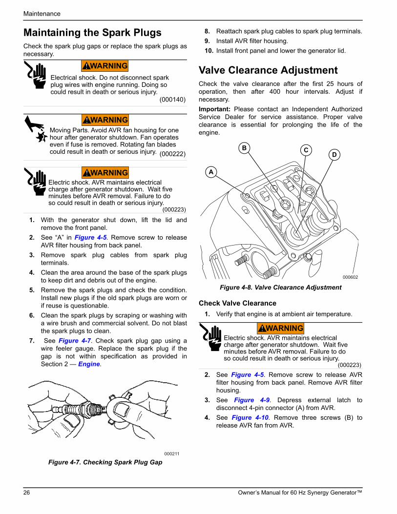
Maintaining the Spark PlugsCheck the spark plug gaps or replace the spark plugs asnecessary.
1. With the generator shut down, lift the lid andremove the front panel.
2. See “A” in Figure 4-5. Remove screw to releaseAVR filter housing from back panel.
3. Remove spark plug cables from spark plugterminals.
4. Clean the area around the base of the spark plugsto keep dirt and debris out of the engine.
5. Remove the spark plugs and check the condition.Install new plugs if the old spark plugs are worn orif reuse is questionable.
6. Clean the spark plugs by scraping or washing witha wire brush and commercial solvent. Do not blastthe spark plugs to clean.
7. See Figure 4-7. Check spark plug gap using awire feeler gauge. Replace the spark plug if thegap is not within specification as provided inSection 2 — Engine.
Figure 4-7. Checking Spark Plug Gap
8. Reattach spark plug cables to spark plug terminals.
9. Install AVR filter housing.
10. Install front panel and lower the generator lid.
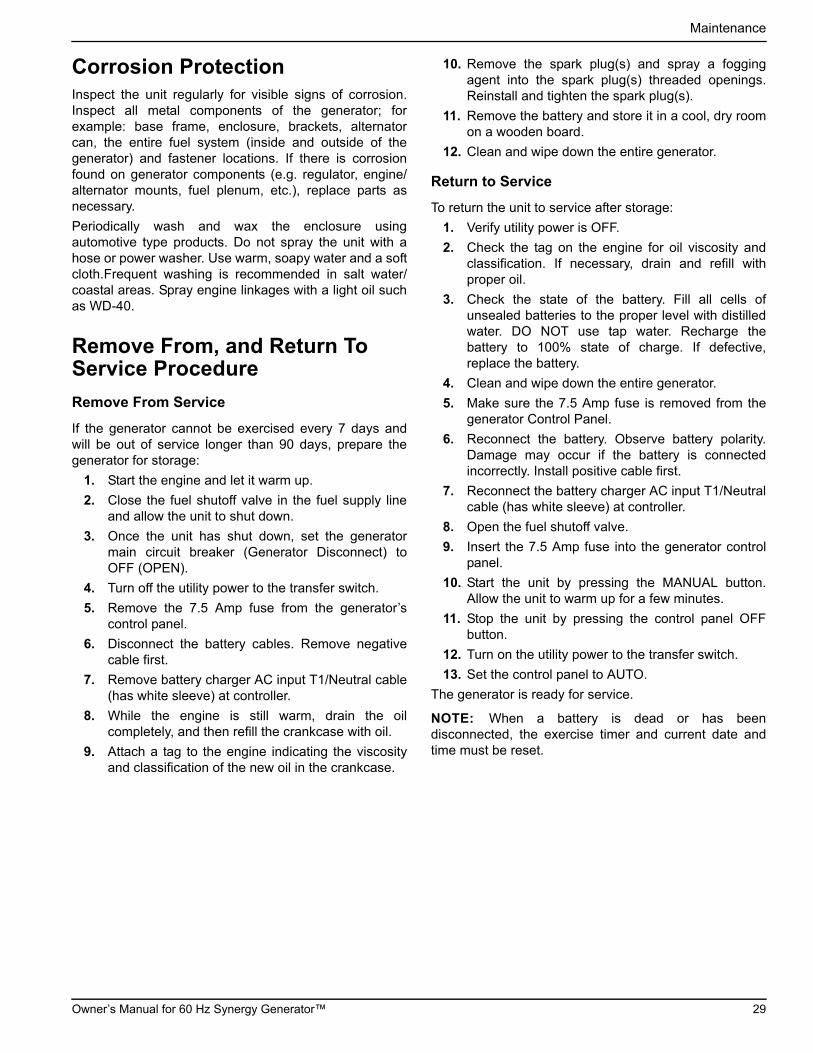
Valve Clearance AdjustmentCheck the valve clearance after the first 25 hours ofoperation, then after 400 hour intervals. Adjust ifnecessary.
Important: Please contact an Independent AuthorizedService Dealer for service assistance. Proper valveclearance is essential for prolonging the life of theengine.
Figure 4-8. Valve Clearance Adjustment
Check Valve Clearance
1. Verify that engine is at ambient air temperature.
2. See Figure 4-5. Remove screw to release AVRfilter housing from back panel. Remove AVR filterhousing.
3. See Figure 4-9. Depress external latch todisconnect 4-pin connector (A) from AVR.
4. See Figure 4-10. Remove three screws (B) torelease AVR fan from AVR.
(000140)
Electrical shock. Do not disconnect spark plug wires with engine running. Doing so could result in death or serious injury.
WARNING
(000222)
WARNINGMoving Parts. Avoid AVR fan housing for onehour after generator shutdown. Fan operates even if fuse is removed. Rotating fan bladescould result in death or serious injury.
(000223)
WARNINGElectric shock. AVR maintains electrical charge after generator shutdown. Wait five minutes before AVR removal. Failure to do so could result in death or serious injury.
000211
000602
A
B CD
(000223)
WARNINGElectric shock. AVR maintains electrical charge after generator shutdown. Wait five minutes before AVR removal. Failure to do so could result in death or serious injury.
26 Owner’s Manual for 60 Hz Synergy Generator™

Maintenance
Figure 4-9. Remove AVR Fan Connector
Figure 4-10. Remove AVR Fan Screws
5. Remove spark plug cables from spark plugterminals.
NOTE: When disconnecting spark plug cable from spark plug terminal, always grasp and pull on the boot at the terminal end of the cable. Pulling on cable portion can result in parts damage.
6. Thoroughly clean area around spark plugs.
7. Remove spark plugs from cylinder head using a 5/8inch spark plug socket.
8. Remove four screws to release valve cover.
9. Move piston to Top Dead Center (TDC) ofcompression stroke (both valves closed). Proceedas follows:
a. Remove intake screen at front of engine to gain access to flywheel nut.
b. Place large socket and socket wrench on fly-wheel nut and rotate engine in a clockwise direction while watching piston through spark plug hole.
NOTE: Piston is at TDC when it is at the highest point of travel.
10. Insert a 0.002 - 0.004 inch (0.05 - 0.1mm) feelergauge between rocker arm and valve stem.Clearance is correct when a slight drag is felt whilesliding feeler gauge back and forth. Verify thatclearances are within the following specification:
• Intake and Exhaust: 0.002 - 0.004 inch (0.05 - 0.1mm)
11. Proceed as follows:
a. If valve clearance adjustment is required, see Adjust Valve Clearance.
b. If valve clearance is within specification, see steps 5-12 under Adjust Valve Clearance.
Adjust Valve Clearance
1. Loosen rocker arm jam nut. Use an Allen wrench to turn the pivot ball stud, while also checking clear-ance between rocker arm and valve stem with the feeler gauge.
NOTE: Hold the rocker arm jam nut in place as the pivot ball stud is turned.
2. When the correct valve clearance is obtained, holdthe pivot ball stud in place with the Allen wrenchand tighten rocker arm jam nut until snug.
3. Using a torque wrench, tighten jam nut to 174 in-lbs (20 N-m).
4. Recheck valve clearance to verify that it did notchange during tightening of the jam nut.
5. Install new valve cover gasket.
6. Start four screws to install valve cover.
7. Verify that valve cover gasket is properlypositioned, and then alternately tighten screws to6-9 ft-lbs (8-12 Nm) using a crosswise pattern
8. Finger tighten spark plugs into cylinder head, andthen using a spark plug socket, tighten to 15-18 ft-lbs (20-25 Nm).
9. Install spark plug cables onto spark plug terminals.
001404
A
001414
B
Owner’s Manual for 60 Hz Synergy Generator™ 27

Maintenance
Battery MaintenanceRegularly inspect the battery per the Service Schedule:
1. With the generator shut down, lift the lid andremove the front panel.
2. Inspect the battery posts and cables for tightnessand corrosion. Tighten and clean as necessary.
3. Check the battery fluid level of unsealed batteries,and if necessary, fill with distilled water only. DONOT use tap water. Also, have the IndependentAuthorized Service Dealer or a qualified ServiceTechnician check the state of charge and condition.
Always recycle batteries in accordance with local lawsand regulations. Contact your local solid waste collectionsite or recycling facility to obtain information on localrecycling processes. For more information on batteryrecycling, visit the Battery Council International websiteat: http://batterycouncil.org.
Strictly observe the following precautions when workingon batteries:
• Remove the 7.5 Amp fuse from the generatorcontrol panel.
• Remove all jewelry—watches, rings, metal objects,etc.
• Use tools with insulated handles.
• Wear rubber gloves and boots.
• Do not place tools or metallic objects on top of thebattery.
• Disconnect the charging source prior to connectingor disconnecting battery terminals.
• Wear full eye protection and protective clothing.
• Where electrolyte contacts the skin, wash it offimmediately with water.
• Where electrolyte contacts the eyes, flushthoroughly and immediately with water and seekmedical attention.
• Wash down spilled electrolyte with an aidneutralizing agent. A common practice is to use asolution of 1 pound (500 grams) bicarbonate ofsoda to 1 gallon (4 liters) of water. The bicarbonateof soda solution is to be added until the evidence ofreaction (foaming) has ceased. The resulting liquidis to be flushed with water and the area dried.
• DO NOT smoke when near the battery.
• DO NOT cause flame or spark in the battery area.
• Discharge static electricity from the body beforetouching the battery by first touching a groundedmetal surface.
Attention After SubmersionIf the generator has been submerged in water, it MUSTNOT be started and operated. Following any submersionin water, have an Independent Authorized Service Dealerthoroughly clean, dry, and inspect the generator. If thestructure (home) has been flooded, it should beinspected by a certified electrician to verify that therewon’t be any electrical problems during generatoroperation or when utility power is returned.
(000162)
WARNINGExplosion. Do not dispose of batteries in a fire. Batteries are explosive. Electrolyte solution can cause
burns and blindness. If electrolyte contacts skin or eyes, flush with water and seek immediate medical attention.
(000137a)
WARNING
(000164)
WARNINGElectrical shock. Disconnect battery groundterminal before working on battery or batterywires. Failure to do so could result in death or serious injury.
(000138a)
WARNING
WARNINGEnvironmental Hazard. Always recycle batteries at an official recycling center in accordance with all local laws and regulations. Failure to do so could result inenvironmental damage, death or serious injury.
(000228)
28 Owner’s Manual for 60 Hz Synergy Generator™
Maintenance
Corrosion ProtectionInspect the unit regularly for visible signs of corrosion.Inspect all metal components of the generator; forexample: base frame, enclosure, brackets, alternatorcan, the entire fuel system (inside and outside of thegenerator) and fastener locations. If there is corrosionfound on generator components (e.g. regulator, engine/alternator mounts, fuel plenum, etc.), replace parts asnecessary.
Periodically wash and wax the enclosure usingautomotive type products. Do not spray the unit with ahose or power washer. Use warm, soapy water and a softcloth.Frequent washing is recommended in salt water/coastal areas. Spray engine linkages with a light oil suchas WD-40.
Remove From, and Return To Service Procedure
Remove From Service
If the generator cannot be exercised every 7 days andwill be out of service longer than 90 days, prepare thegenerator for storage:
1. Start the engine and let it warm up.
2. Close the fuel shutoff valve in the fuel supply lineand allow the unit to shut down.
3. Once the unit has shut down, set the generatormain circuit breaker (Generator Disconnect) toOFF (OPEN).
4. Turn off the utility power to the transfer switch.
5. Remove the 7.5 Amp fuse from the generator’scontrol panel.
6. Disconnect the battery cables. Remove negativecable first.
7. Remove battery charger AC input T1/Neutral cable(has white sleeve) at controller.
8. While the engine is still warm, drain the oilcompletely, and then refill the crankcase with oil.
9. Attach a tag to the engine indicating the viscosityand classification of the new oil in the crankcase.
10. Remove the spark plug(s) and spray a foggingagent into the spark plug(s) threaded openings.Reinstall and tighten the spark plug(s).
11. Remove the battery and store it in a cool, dry roomon a wooden board.
12. Clean and wipe down the entire generator.
Return to Service
To return the unit to service after storage:
1. Verify utility power is OFF.
2. Check the tag on the engine for oil viscosity andclassification. If necessary, drain and refill withproper oil.
3. Check the state of the battery. Fill all cells ofunsealed batteries to the proper level with distilledwater. DO NOT use tap water. Recharge thebattery to 100% state of charge. If defective,replace the battery.
4. Clean and wipe down the entire generator.
5. Make sure the 7.5 Amp fuse is removed from thegenerator Control Panel.
6. Reconnect the battery. Observe battery polarity.Damage may occur if the battery is connectedincorrectly. Install positive cable first.
7. Reconnect the battery charger AC input T1/Neutralcable (has white sleeve) at controller.
8. Open the fuel shutoff valve.
9. Insert the 7.5 Amp fuse into the generator controlpanel.
10. Start the unit by pressing the MANUAL button.Allow the unit to warm up for a few minutes.
11. Stop the unit by pressing the control panel OFFbutton.
12. Turn on the utility power to the transfer switch.
13. Set the control panel to AUTO.
The generator is ready for service.
NOTE: When a battery is dead or has beendisconnected, the exercise timer and current date andtime must be reset.
Owner’s Manual for 60 Hz Synergy Generator™ 29

Maintenance
This page intentionally left blank.
30 Owner’s Manual for 60 Hz Synergy Generator™

Troubleshooting / Quick Reference Guide
Section 5: Troubleshooting / Quick Reference Guide
General Troubleshooting
Table 5-1. General Troubleshooting
Problem Cause Correction
Engine will not crank. 1. Fuse blown.
2. Loose, corroded or defective battery cables.
3. Defective starter contact.
4. Defective starter motor.
5. Dead battery.
1. Correct short circuit condition by replacing 7.5 Amp fuse in generator control panel.
2. Tighten, clean or replace as necessary.*
3. *See #2.
4. *See #2.
5. Charge or replace battery.
Engine cranks but will not start.
1. Out of fuel.
2. Defective fuel solenoid (FS).
3. Open Wire 14 from engine control board.
4. Defective spark plug(s).
5. valve clearance out of adjustment.
1. Replenish fuel / Turn on fuel valve.
2. *
3. *
4. Clean, re-gap or replace plug(s).
5. Reset valve clearance.
Engine starts hard and runs rough.
1. Air cleaner plugged or damaged.
2. Defective spark plug(s).
3. Fuel pressure incorrect.
4. Fuel selector in wrong position.
1. Check / replace air cleaner.
2. Clean or replace spark plug.
3. Confirm fuel pressure to regulator is 10–12 in. water column (19–22 mm mercury) for LP, and 3.5–7 in. water column (9–13 mm mercury) for natural gas.
4. Turn fuel conversion valve to correct position.
Generator is set to OFF, but the engine continues to run.
1. Controller wired incorrectly
2. Defective control board.
1. *
2. *
No AC output from generator.
1. Main line circuit breaker is in the OFF (or OPEN) position.
2. Generator internal failure.
1. Reset circuit breaker to ON (or CLOSED).
2. *
No transfer to standby after utility source failure.
1. Main line circuit breaker is in the OFF (or OPEN) position.
2. Defective transfer switch coil.
3. Defective transfer relay.
4. Transfer relay circuit open.
5. Defective control logic board.
1. Reset circuit breaker to ON (or CLOSED).
2. *
3. *
4. *
5. *
Unit consumes large amounts of oil.
1. Engine over filled with oil.
2. Engine breather defective.
3. Improper type or viscosity of oil.
4. Damaged gasket, seal or hose.
1. Adjust oil to proper level.
2. *
3. See Engine Oil Requirements.
4. Check for oil leaks.
* Contact an Independent Authorized Service Dealer for assistance.
Owner’s Manual for 60 Hz Synergy Generator™ 31

Troubleshooting / Quick Reference Guide
Synergy Troubleshooting
Table 5-2. Synergy Troubleshooting
Ecode/Active Alarm
LED Problem Things toCheck
Possible Causes/Solution
1048 VSCF Overload RED Unit shuts down during operation.
Check the LEDs/Screen for alarms.
Alternator, AVR or wiring is damaged. Contact an Independent Authorized Servicing Dealer.
1049 VSCF Overload RED Unit shuts down during operation.
Check the LEDs/Screen for alarms.
Generator output is shorted or severely overloaded. Identify and clear the overload, and then restart.
1051 VSCF High Battery
YELLOW Yellow LED illuminated in any state.
Check the LEDs/Screen for alarms.
Voltage supply to the AVR is high. If an external battery charger is in use, contact installing dealer to correct installation. If an external battery charger is NOT in use, contact an Independent Authorized Servicing Dealer.
1052 VSCF DC Overvoltage
RED Unit shuts down during operation.
Check the LEDs/Screen for alarms.
Probable causes are:
1) The generator was temporarily overloaded.
2) The output was temporarily shorted. Try to restart the unit.
1053 VSCF Gate Fault
RED Unit shuts down during operation or starting.
Check the LEDs/Screen for alarms.
AVR is damaged. Contact an Independent Authorized Servicing Dealer.
1054 VSCF IGBT Overtemp.
RED Unit shuts down during operation or starting.
Check the LEDs/Screen for alarms.
Probable causes are:
1) Replace AVR filter. Inspect fan.
2) Intake or exhaust air path is blocked. Check intake and exhaust.
3) The BIG fan is not running (only runs when the engine is running). KEEP FINGERS AWAY FROM FAN HOUSING—PERSONAL INJURY CAN OCCUR IF FAN IS RUNNING. Contact an Independent Authorized Servicing Dealer.
4) Air leak in AVR enclosure. Contact an Independent Authorized Servicing Dealer.
5) Engine running too hot. Inspect air intake and exhaust.
6) Ambient temperature has risen above 60 ºF (15.5 °C). Derate the generator output per specifications.
1055 VSCF Phase Error
RED Unit shuts down during starting.
Check the LEDs/Screen for alarms.
An incorrect voltage and frequency has been detected during starting. Probable causes are:
1) Alternator damage. Contact an Independent Authorized Servicing Dealer.
2) Generator has started into a severe load. Manually operate transfer switch back to utility position and try to restart unit. If problem persists, remove load and attempt to restart unit again.
3) The engine may not be reaching its prescribed speed. Proceed as follows:
•Verify stepper motor is moving and linkage is free.
•Verify stepper motor is plugged in.
•Verify gas pressure is within specified limits.
1056 VSCF Undervoltage
RED Unit shuts down during operation or starting.
Check the LEDs/Screen for alarms.
The generator output voltage is too low. Probable causes are:
1) The load is too large. Remove load and attempt to restart unit.
2) Alternator or AVR damage. Contact an Independent Authorized Servicing Dealer.
32 Owner’s Manual for 60 Hz Synergy Generator™

Troubleshooting / Quick Reference Guide
1057 VSCF Overvoltage
RED Unit shuts down during operation or starting.
Check the LEDs/Screen for alarms.
Probable causes are:
1) The generator has been overloaded. Remove load and attempt to restart unit.
2) Generator has started into a severe load. Manually operate transfer switch back to utility position and try to restart unit. If problem persists, remove load and attempt to restart unit again.
1058 VSCF DC Undervoltage
RED Unit shuts down during operation or starting.
Check the LEDs/Screen for alarms.
The DPE winding supplies this voltage.
1) Alternator damage. Contact an Independent Authorized Servicing Dealer.
1059 VSCF Field Loss
RED Unit shuts down during starting.
Check the LEDs/Screen for alarms.
Unit detects no output voltage while starting.
1) Alternator damage. Contact an Independent Authorized Servicing Dealer.
1061 VSCF Field Loss
RED Unit shuts down during operation.
Check the LEDs/Screen for alarms.
Unit detects loss of output voltage while running.
1) Alternator damage. Contact an Independent Authorized Servicing Dealer.
1060 Big Fan Failure RED Unit shuts down during operation.
Check the LEDs/Screen for alarms.
This alarm occurs when the AVR electronics temperature exceeds 158 °F (70 °C). Possible causes are:
1) AVR filter faulty. Replace AVR filter.
2) Intake or exhaust air path is blocked. Check intake and exhaust.
3) The BIG fan is not running (only runs when the engine is running). KEEP FINGERS AWAY FROM FAN HOUSING— PERSONAL INJURY CAN OCCUR IF FAN IS RUNNING. Contact an Independent Authorized Servicing Dealer.
4) Air leak in AVR enclosure. Contact an Independent Authorized Servicing Dealer.
5) Engine running too hot. Inspect air intake and exhaust.
6) Ambient temperature has risen above 60 ºF (15.6 °C). Derate the generator output per specifications.
If message is displayed when generator is stopped, also check SMALL fan. Small fan RUNS for 60 minutes after generator is stopped and keeps electronics cool during heat soak.
1065 Overfrequency RED Unit shuts down during operation.
Check the LEDs/Screen for alarms.
Probable causes are:
1) Overload. Remove load and attempt to restart unit.
2) RPM sensor has failed. Contact an Independent Authorized Servicing Dealer.
3) Stepper motor problem. Contact an Independent Authorized Servicing Dealer.
Table 5-2. Synergy Troubleshooting
Ecode/Active Alarm
LED Problem Things toCheck
Possible Causes/Solution
Owner’s Manual for 60 Hz Synergy Generator™ 33

Troubleshooting / Quick Reference Guide
Load Shed Troubleshooting
1066 VSCF Speed mismatch
RED Unit shuts down during Operation or starting.
Check the LEDs/Screen for alarms.
1) Fuel problem (pressure loss). Check fuel supply and attempt to restart unit.
2) A large load is not wired through the load shed module. Contact installing dealer to correct installation.
3) Large overload. Remove load and attempt to restart unit.
4) Throttle or engine problem. Contact an Independent Authorized Servicing Dealer.
1070 Small fan failure
YELLOW “Small fan failure” is displayed. If unit was running in AUTO and utility returns, it will continue to run for one hour to cool electronics without fan.
Check the LEDs/Screen for alarms.
Small fan current incorrect. Probable causes are:
1) Fan wiring or mechanical problem. Contact an Independent Authorized Servicing Dealer.
2) Air path is blocked. Check AVR filter.
KEEP FINGERS AWAY FROM FAN HOUSING— PERSONAL INJURY CAN OCCUR IF FAN IS RUNNING.
Table 5-2. Synergy Troubleshooting
Ecode/Active Alarm
LED Problem Things toCheck
Possible Causes/Solution
Table 5-3. Load Shed Troubleshooting
Symptom Possible Causes
Generator stalls when large load is supplied.
1) Total load is too big for the generator and fuel type. Contact installing dealer to correct installation.
2) A large load is not wired through the load shed module. Contact installing dealer to correct installation.
Large loads keep getting shed and locked out (load LED goes out for 30 minutes).
Total load is too big for generator. Contact installing dealer to correct installation.
Output voltage is low/high. Voltage calibration incorrect. Contact an Independent Authorized Servicing Dealer.
Generator does not pull full power. Current calibration incorrect. Contact an Independent Authorized Servicing Dealer.
34 Owner’s Manual for 60 Hz Synergy Generator™

Troubleshooting / Quick Reference Guide
This page intentionally left blank.
Owner’s Manual for 60 Hz Synergy Generator™ 35

Troubleshooting / Quick Reference Guide
Quick Reference GuideTo clear an active alarm, press the ENTER button twice and then press AUTO. If the alarm reoccurs, contact an Independent Authorized Service Dealer.
Table 5-4. Quick Reference Guide
Active Alarm LED Problem Things to Check Solution
NONE GREENUnit running in AUTO but no power in house.
Check MLCB.
Check MLCB if the MLCB is in the ON position. If it is in the ON position contact the Independent Authorized Service Dealer.
HIGH TEMPERATURE
REDUnit shuts down during operation.
Check the LEDs / Screen for alarms.
Check ventilation around the generator, intake, exhaust and rear of generator. If no obstruction contact Independent Authorized Service Dealer.
OVERLOAD REMOVE LOAD
REDUnit shuts down during operation.
Check the LEDs / Screen for alarms.
Clear alarm and remove household loads from the generator. Put back in AUTO and restart.
RPM SENSE LOSS REDUnit was running and shuts down, attempts to restart.
Check the LEDs / Screen for alarms.
Clear alarm and remove household loads from the generator. Put back in AUTO and restart. If generator does not start, contact Independent Authorized Service Dealer.
NOT ACTIVATED NONEUnit will not start in AUTO with utility loss.
See if screen says unit not activated.
Refer to activation section in Installation Guidelines Manual.
NONE GREENUnit will not start in AUTO with utility loss.
Check screen for start delay countdown.
If the start up delay is greater than expected, contact Independent Authorized Service Dealer to adjust from 2 to 1500 seconds.
LOW OIL PRESSURE
REDUnit will not start in AUTO with utility loss.
Check the LEDs / Screen for alarms.
Check oil and add oil per Owners Manual. If oil level is correct, contact Independent Authorized Service Dealer.
RPM SENSE LOSS REDUnit will not start in AUTO with utility loss.
Check the LEDs / Screen for alarms.
Clear alarm. Using the control panel, check the battery by navigating to the BATTERY MENU option from the MAIN MENU. If it states battery is GOOD, contact Independent Authorized Service Dealer. If it states CHECK BATTERY, replace the battery.
OVERCRANK REDUnit will not start in AUTO with utility loss.
Check the LEDs / Screen for alarms.
Check fuel line shutoff valve is in the ON position. Clear alarm. Attempt to start the unit in MANUAL. If it does not start or starts and runs rough, contact Independent Authorized Service Dealer.
LOW VOLTS REMOVE LOAD
REDUnit will not start in AUTO with utility loss.
Check the LEDs / Screen for alarms.
Clear alarm and remove household loads from the generator. Put back in AUTO and restart.
FUSE PROBLEM REDUnit will not start in AUTO with utility loss.
Check the LEDs / Screen for alarms.
Check the 7.5 Amp fuse. If it is bad replace it with an ATO 7.5 Amp fuse, if not contact Independent Authorized Service Dealer.
OVERSPEED REDUnit will not start in AUTO with utility loss.
Check the LEDs / Screen for alarms.
Contact Independent Authorized Service Dealer.
UNDERVOLTAGE REDUnit will not start in AUTO with utility loss.
Check the LEDs / Screen for alarms.
Contact Independent Authorized Service Dealer.
36 Owner’s Manual for 60 Hz Synergy Generator™

Troubleshooting / Quick Reference Guide
UNDERSPEED REDUnit will not start in AUTO with utility loss.
Check the LEDs / Screen for alarms.
Contact Independent Authorized Service Dealer.
STEPPER OVERCURRENT
REDUnit will not start in AUTO with utility loss.
Check the LEDs / Screen for alarms.
Contact Independent Authorized Service Dealer.
MISWIRE REDUnit will not start in AUTO with utility loss.
Check the LEDs / Screen for alarms.
Contact Independent Authorized Service Dealer.
OVERVOLTAGE REDUnit will not start in AUTO with utility loss.
Check the LEDs / Screen for alarms.
Contact Independent Authorized Service Dealer.
LOW BATTERY YELLOWYellow LED illuminated in any state.
Check the screen for additional information.
Clear alarm. Using the control panel, check the battery by navigating to the BATTERY MENU option from the MAIN MENU. If it states battery is GOOD contact Independent Authorized Service Dealer. If it states CHECK BATTERY, replace the battery.
BATTERY PROBLEM
YELLOWYellow LED illuminated in any state.
Check the screen for additional information.
Contact Independent Authorized Service Dealer.
CHARGER WARNING
YELLOWYellow LED illuminated in any state.
Check the screen for additional information.
Contact Independent Authorized Service Dealer.
SERVICE A YELLOWYellow LED illuminated in any state.
Check the screen for additional information.
Perform SERVICE A maintenance. Press ENTER to clear.
SERVICE B YELLOWYellow LED illuminated in any state.
Check the screen for additional information.
Perform SERVICE B maintenance. Press ENTER to clear.
INSPECT BATTERY YELLOWYellow LED illuminated in any state.
Check the screen for additional information.
Inspect Battery. Press ENTER to clear.
Table 5-4. Quick Reference Guide
Active Alarm LED Problem Things to Check Solution
Owner’s Manual for 60 Hz Synergy Generator™ 37

Troubleshooting / Quick Reference Guide
This page intentionally left blank.
38 Owner’s Manual for 60 Hz Synergy Generator™


Part No. 0K2502 Rev. E 12/11/15 Printed in USA©2015 Generac Power Systems, Inc. All rights reservedSpecifications are subject to change without notice.No reproduction allowed in any form without prior written consent from Generac Power Systems, Inc.
Generac Power Systems, Inc.S45 W29290 Hwy. 59Waukesha, WI 53189
1-888-GENERAC (1-888-436-3722)generac.com


