
Gen 3 Drives for HEIDENHAIN Controls...A HEIDENHAIN control system with a modular inverter system...
80
Gen 3 Drives For HEIDENHAIN Controls Information for the Machine Tool Builder 03/2020
Transcript of Gen 3 Drives for HEIDENHAIN Controls...A HEIDENHAIN control system with a modular inverter system...

Gen 3 DrivesFor HEIDENHAIN Controls
Information for theMachine Tool Builder
03/2020

HEIDENHAIN inverter systems
The Gen 3 inverter systems from HEIDENHAIN are suitablefor the operation of HEIDENHAIN controls with digital speedcontrol and communication via Gbit HSCI. These drives aredesigned for the operation of synchronous and asynchronousmotors from HEIDENHAIN.
UVR 340, CC 3xxwith modular inverters
Intended use The products described in this brochure:• may be used only for NC-controlled machine tools,• may be used only in an industrial setting, for commercial
applications, or in research institutions,• must be operated in accordance with the product
requirements (specifications, environmental data, safetyinstructions, etc.),
• and must be operated in an electrical cabinet.
The machine manufacturer must ensure that the end productmeets all of the requirements of the Machinery Directive(2006/42/EC). This is particularly the case when the devices areused as part of a safety function.
Improper use The devices are not intended for applications in areas wherea failure would result in considerable risk to humans or theenvironment. Usage in potentially explosive atmospheres isprohibited.
System test Controls, motors, and encoders from HEIDENHAIN are usuallyintegrated as components into complete systems. In suchcases, comprehensive testing of the complete system isrequired, irrespective of the specifications of the individualdevices.
Parts subject towear
Power modules (power supply units, inverters, and compactinverters) from HEIDENHAIN contain parts subject to wear—particularly fans.
Standards Standards (ISO, EN, etc.) apply only where explicitly stated inthis brochure.
Validity This brochure supersedes all previous editions, which therebybecome invalid. Subject to change without notice.
Precondition This brochure contains basic information about the selectionof the components. All of the descriptions and specificationsprovided in the Technical Manuals must always be compliedwith.
2

Contents
HEIDENHAIN inverter systems 2
Modular inverter systems 8
Accessories for inverter systems 36
Overview of cables 51
Mounting information 53
Dimensions 56
Subject index 78
3

HEIDENHAIN inverter systems
HEIDENHAIN Gen 3 inverter systems are available with apower rating ranging from 15 kW to 135 kW. Their modularversions are available as regenerative systems.
UVR 340
Regenerativeinverter systems
With regenerative inverter systems, the braking energyof the motor is fed back into the power supply network. Forthis purpose, regenerative modular inverter systems requireadditional components such as a line filter and a commutatingreactor (see Accessories for inverter systems).
Non-regenerativeinverter systems
With non-regenerative inverter systems, the braking energyof the motors is converted into heat. This requires a brakingresistor (see Accessories for inverter systems).
Supply voltage For the respective supply voltage, please refer to thefollowing specifications. The inverter systems are intendedfor connection to a TN supply network. Other power supplynetworks or other line voltages may need to be adaptedby means of a transformer. HEIDENHAIN recommends aTN-S, TN-C, or TN-C-S network for the operation of its powermodules. Please refer to the Technical Manual of your invertersystem.
4

DC-link voltage Both inverter systems use a rectifier bridge circuit to convertthe connected line power into the DC-link voltage and otherauxiliary voltages for the power module electronics and othercontrol components, such as the controller unit and maincomputer. The rectified and—in the case of a UVR 3xx powersupply unit—regulated DC-link voltage is directed through theIGBTs to the motors with controlled frequency and voltage.Control is accomplished by PWM signals.
The DC-link voltage is DC650V or DC720 V for modularsystems with a UVR 3xx.
Safety functionsfor external safety
HEIDENHAIN inverter systems enable the centralized switch-off of the inverters via special inputs for deactivating the pulseenable for the PWM-driving of the IGBTs (e.g., in the eventof an emergency stop). This is equivalent to the STO safetyfunction. The Gen 3 inverters also support a dual-channelSBC braking system via corresponding outputs directly on theinverter. In addition, the machine manufacturer can configure anSS1 stop reaction in which emergency stop braking to standstillis performed, controlled by the controller unit.
If needed, up to eight axis groups can be formed for whichseparate switch-off is possible (e.g., axes for the toolmagazine). For controls without integrated functional safety(FS), the safety functions are triggered over a special PLmodule for the drive enable.
5

Integratedfunctionalsafety (FS)
HEIDENHAIN also offers control systems with integratedfunctional safety (FS). These control systems offer a series ofsafety functions (STO, SLS, SLP, SBC, SS1, SS2, and safe PLCprogram), as well as easy implementation of up to four safety-related operating modes.
Control systems with functional safety (FS) feature twoindependently operating, redundant safety channels thatcollect, process, and output all safety-relevant signals. Formore information on this topic, please refer to the Gen 3 drivesTechnical Manual and the Functional Safety (FS) TechnicalManual.
Functional safety (FS) is scalable by means of software options.Only the number of safe motors that you actually need mustbe enabled. For more information on these software options,please refer to the brochure for your control:
Brochure ID
TNC 640 896020-xx
TNC 620 895922-xx
TNC 320 1113513-xx
TNC 128 827228-xx
CNC PILOT 640 896094-xx
MANUALplus 620 743682-xx
Modular inverters Modular inverter systems consist of the following modules:• A UVR supply unit, including the necessary additional
components (e.g., KDR, line filter)• Multiple UM power modules for axes and spindles• One or more controller units and an HFL cable for controlling
the inverters• Accessories such as the CMH 3xx or UP 3xx
In modular systems, the UVR power supply unit produces therectified DC-link voltage. The IGBT full bridges are housedin the separate UM power modules. The DC-link power barconducts the DC-link voltage to the power modules. The UMsare supplied with the necessary 24 V supply voltage over the24 V bus mounting.
The controller unit is connected to the modular inverters via theHFL cable and drives the IGBTs by means of PWM signals.
UM 315
Additional powersupply
Power supply units additionally have a DC24 V output (X90connector). This voltage is DC-link-buffered and can be used tosupply the MC main computer and other control componentswith a 24 V power supply.
Safety parameters For HEIDENHAIN devices, such as control components,encoders, and motors, your HEIDENHAIN contact person canprovide you with device-specific, safety-relevant parametersupon request (failure rates, information on fault exclusion, etc.).
6

Power supplyfor connectedmodules
The current consumption of the electronics of the modularinverters and controller units is largely dependent on theirpower rating. Thus, in the planning stage of the control system,please check the current consumption of the DC24 V supply inthe Specifications. The power supply unit’s own consumptiondoes not need to be considered in this context.
The UVR power supply units feature an additional integratedpower adapter that provides a DC 24 V voltage for the controlsystem and other PLC components:• Supply of components that are connected to the 24 V bus
mounting of the inverter group (inverters and their brakes,controller units, and electrical cabinet version of the maincomputer)
• Supply of further control components such as the maincomputer in the operating panel, monitor, machine operatingpanel, PL modules, etc.
• Supply of machine-specific PLC components, such as 24Vrelays
The integrated power adapter is buffered by the DC link,thereby ensuring that, in the event of a power failure, theconnected components will continue to be supplied so thatany concluding actions, such as the LIFTOFF function, can stillbe performed. A complete power failure must be consideredseparately. As the machine manufacturer, you should considermeasures for the event of a power failure where applicable.
For the performance data of the power adapter, please refer tothe specifications. In the planning stage, please also considerthe power requirements of the connected inverters, encoders,and controller units, in addition to the HSCI/PLC components.For further information on project planning, please refer to theTechnical Manual of your inverter system.
The +24 V supply voltage is required for the complete controlsystem as a safely separated voltage. These safely separatedcircuits must not be mixed with or connected to supply circuitswith basic insulation or other supply circuits.
UVR 350
Motor currents The modular inverters are available in grades that permitexcellent adaptation to the required motor currents andtorques. In addition, the PWM frequency can be adjusted tothe motor current. Please bear in mind that very high spindlespeeds require a higher PWM frequency.
HFL cable and busmounting
The individual modular inverters are connected via HFL cables(optical fiber), connectors for the 24 V bus mounting, and DC-link busbars. The HFL cables must be cut or ordered to theproper length and are not included in delivery.
The connectors for the 24 V bus mounting and the DC-linkbusbars for the specific device are included in delivery.
7

Modular inverter systemsSystem overview
A HEIDENHAIN control system with a modular inverter systemtypically consists of the following components:• MC main computer, monitor, keyboard, and machine
operating panel• PLB 62xxFS or PLB 62xx system PL and PAE-H 08-00-01• CC controller unit• UVR 3xx power supply unit• UM 3xx modular inverters• KDR 3xx commutating reactor• Line filter for the UVR 3xx• Siemens SITOR gR or gS line fuse• UP 3xx braking resistor module (optional)• Surge protector (optional)• SM 3xx voltage protection module (optional)• CMH 3xx capacitor module (optional)• Shielded motor power cables• Feed and spindle motors
The Gen 3 drives are characterized by the following features:• Higher peak and nominal currents with an overall more
compact enclosure design• Fast Gbit HSCI communication extending all the way to
the UVR 3xx power supply unit, for greater flexibility andimproved diagnostics
• Digital HFL (HEIDENHAIN Fiber Link) cable for control of theinverters, for faster and interference-free data transfer
• Contiguous bus mounting for supply voltages (DC link, 24 V),allowing for very simple wiring and any desired arrangementor sequence of the power supply unit, power modules,controller unit, and main computer
• Hybrid connector for the connection of motor phases, thebrake, and the shield—all with a single connecting element
• New, miniaturized connector technology for the connection ofpurely serial EnDat encoders
8

Example of the structure of a modular inverter system:
UM 3
xx
UVR 3xx
UM 3
xxUM
3xx
UM 3
xxUP 3
xx
CMH 3
xxCC 3
xx
1
1
2
3
4
6
9
7
58
1 HSCI connection to the UVR and CC, Gbit HSCI cable (ID 1257765-xx) or for > 15 m (ID 1306923-xx)
2 HFL connection (optical fiber cable) between the CC and UM with the ID 1265351-xx (cut to size or on a roll)3 Encoder inputs: 1 VPP or EnDat4 Encoder inputs: EnDat 2.25 DC-link bus mounting of the UVR and UM;
the required bars are supplied with the corresponding component6 Protective conductor connection of each individual component;
comply with the specifications in the Technical Manual7 +24 V bus mounting of the UVR, UM, CC, and accessories;
the required connectors are supplied with the corresponding component8 Cover for DC-link connection and 24 V supply bar9 Handle strip for easy transport of the components
9

Gbit HSCI The introduction of the Gen 3 drives includes the transitionto faster Gbit HSCI communication between the controlcomponents. Gbit HSCI allows the additional diagnostic dataof the Gen 3 components to be transmitted and opens upnew possibilities for expanding the range of functions in thefuture. A transition to Gbit HSCI is therefore required for allHSCI components of the control system. Control componentsthat support Gbit HSCI are labeled as “Gen 3 ready”. The IDnumbers or variants of the necessary HSCI components (MC,MB, TE, HSCI cable) are stated in your control's TechnicalManual.
Permissiblenumber ofcomponents
Maximum permissible number of individual Gbit HSCIcomponents:
Gbit HSCI component Maximum number in the control system
MC, IPC HSCI master 1
CC, UEC HSCI slave 41)
UVR HSCI slave 4
MB, PLB 600x HSCI slave 2
PLB 6xxx HSCI slave 7
PLB 6xxxFS HSCI slave 2
HR 5
PLD-H xx-xx-xx FS in PLB 6xxxFS 102)
PLD-H xx-xx-xx, PLA-H xx-xx-xx
in PLB 6xxx(FS) 252)
PAE-H xx-xx-xx in PLB 62xx 1 (only in systems without integrated functionalsafety FS)
1) Controller motherboards distributed to CC or UEC as desired2) Total maximum of 1000 inputs/outputs
In an HSCI system however, a maximum of 13 HSCI slavesare permissible. Make sure during planning that this maximumnumber is not be exceeded.
10

Differences between the inverter systems
Brief overview The following images provide a comparison of the currentlyavailable inverter systems:
1xx inverter systems (UVR 1xx, UM 1xx, UE 2xx, UR 2xx, UEC 1xx)
Gen 3 drives
11

Inverter systemsbased on devices
Device/function 1xx inverter system Gen 3 drives
Inverter UM 1x1 to UM 1x7 UM 3x0 to UM 3x7
Power supply unit UVR 130 to UVR 170UV 130 D
UVR 330 to UVR 370UEC 3xx, not yet available
Controller unit CC 6106, CC 6108, and CC 6110
CC 302, CC 306, CC 308, and CC 310
Compact inverter UEC 1xx, UE 2xx, and UR 2xx UEC 3xx, not yet available
Regenerative module forcompact inverter
None RM 330, not yet available
DC-link filter ZKF 1x0 Not required
Commutating reactor KDR 120 to KDR 170 KDR 330 to KDR 370
Line filter EPCOS 35A to 200A EPCOS 46 A to 202 A
DC-link capacitormodule
CMH 120 CMH 320
Braking resistor UP 110 and UP 120 UP 310 and UP 320
Power adapter PSL 13x Integrated into the power supply unit
External safety Axis-enable module(s), ID 573732-xx
PAE-H 08-00-01, ID 1203881-xx
Wiring of the powermodules
Ribbon cables for PWM signals, devicebus, and supply bus
Optical fiber cables (HFL), busmountings
Covers Covers for ribbon cables Not required
Multi-row configuration MS 11x Connection kits for convenient wiring
24 V capacitor module CML 110, ID 574087-xx
Not required
Control components MC, MB, TE, PLB with 100 Mbit HSCI
MC, MB, TE, PLB with Gbit HSCI
Motor power cables Unshielded cables Shielded cables
Adapter module Adapter module, ID 352762-xx
Not required
Fan unit For the UM 116D and UVR 170D, ID 749973-xx
Not required
Water cooling Hose kit, ID 584862-01
Hose kit, ID 584862-01
12

Differences basedon ID number
Power supply units 1xx inverter systems Gen 3 drives
UVR 120D ID 1095625-xx
UVR 130D ID 1095626-xx
UVR 330 ID 1164511-xx
UVR 140D ID 1084190-xx UVR 340 ID 1168321-xx
UVR 150D ID 1080611-xx UVR 350 ID 1064350-xx
UVR 160D ID 1095627-xx UVR 360 ID 1118870-xx
UVR 160DW ID 1095809-xx UVR 360W ID 1237086-xx
UVR 170D ID 807429-xx UVR 370 ID 1163158-xx
UVR 170DW ID 546911-xx UVR 370W ID 1237988-xx
UV 130 D ID 824215-xx UEC 3xx Not yet available
Modular inverters 1xx inverter systems Gen 3 drives
UM 111D ID 667945-xx UM 3101) ID 1108101-xx
UM 111BD ID 671968-xx UM 3111) ID 1108147-xx
UM 112D ID 731984-xx UM 312 ID 1108153-xx
UM 113D ID 730435-xx UM 313 ID 1108164-xx
UM 114D ID 671288-xx UM 314 ID 1108167-xx
UM 115D ID 671566-xx UM 315 ID 1129203-xx
UM 116D ID 667954-xx UM 316 ID 1123915-xx
UM 116DW ID 667946-xx UM 316W ID 1237090-xx
UM 117DW ID 689572-xx UM 317W ID 1237092-xx
UM 121D ID 667838-xx UM 3201) ID 1073027-xx
UM 121BD ID 667942-xx UM 3211) ID 1107902-xx
UM 122D ID 667633-xx UM 322 ID 1043586-xx
1) Connectors for motor and brake connections must be ordered separately (ID 1249132-xx)
Comply with the specifications for the modular inverters whenmigrating to the new inverter generation. The UM 3xx devicesare more powerful than the previous UM 1xx units. Dependingon the motor or drive system, it may be possible to use asmaller inverter with the UM 3xx devices.
13

Commutatingreactors
1xx inverter systems Gen 3 drives
KDR 120 ID 344505-xx
KDR 130C ID 646271-xx
KDR 330 ID 1164204-xx
KDR 140 ID 333068-xx KDR 340 ID 1164205-xx
KDR 150 ID 355253-xx KDR 350 ID 1164206-xx
KDR 160 ID 573265-01 KDR 360 ID 1164276-xx
KDR 170 ID 735563-xx KDR 370 ID 1164277-xx
Line filters 1xx inverter systems, without star point Gen 3 drives, with S star point
EPCOS 35 A ID 676759-xx EPCOS 46 A ID 1169716-xx
EPCOS 80 A ID 640908-xx EPCOS 83 A ID 1169717-xx
EPCOS 120 A ID 575292-xx EPCOS 135 A ID 1169718-xx
EPCOS 200 A ID 735542-xx EPCOS 202 A ID 1169719-xx
Braking resistor,capacitor, andvoltage-protectionmodules
1xx inverter systems Gen 3 drives
UP 110 ID 341516-xx UP 310 ID 1119332-xx
UP 120 ID 605731-xx UP 320 ID 1119330-xx
SM 110 ID 368453-xx SM 320 ID 1276063-xx
SM 130 ID 540739-xx SM 330 ID 1237089-xx
CMH 120 ID 59116-01 CMH 320 ID 1164215-xx
Controller units 1xx inverter systems Gen 3 drives
- CC 302 ID 1243183-xx
CC 6106 ID 662636-xx CC 306 ID 1074384-xx
CC 6108 ID 662637-xx CC 308 ID 1074385-xx
CC 6110 ID 662638-xx CC 310 ID 1243647-xx
Please note that, in contrast to the CC 61xx controller units,only half of the encoder inputs on a CC 3xx are designed forencoders with 1 Vpp or EnDat interface.
14

Connecting cablesof the power mod-ules and controlcomponents
1xx inverter systems Gen 3 drives
Ribbon cable for CCsupply voltage
ID 325816-xx Not required
Ribbon cable for supplybus
ID 325816-xx Not required
Ribbon cable for devicebus
ID 325817-xx Not required
Ribbon cable for PWMconnection
ID 250479-xx Optical fiber cable ID 1265351-xx
Adapter module fortemperature sensor
ID 336377-xx, ID 312533-xx
Can continue to be used at X40x of the CC 3xx
HSCI cable ID 618893-xx Gbit HSCI cable up to 15 m:ID 1257765-xxfrom 17 m to 70 m:ID 1306923-xx
Monitor cable ID 625901-xx New HDL2 interface ID 1161508-xx
PWM covers ID 329031-xx, ID 538427-xx, ID 1102784-xx
Not required
MS 11x ID 658132-xx,ID 673685-xx
Connection kits forconvenient wiring
ID 1274603-xx and ID 1278910-03
Panel MCs 1xx inverter systems Gen 3 drives
MC 7410 1039531-11
MC 7420 1066650-02
MC 8410 1175057-01
MC 8410 1175057-xx
MC 7410T 1034791-01
MC 8420T 1213689-01
MC 8420T 1213689-xx
MC 7522 1071597-02
MC 8512 1243919-01
MC 8512 1243919-xx
MC 7532 1124449-01, -02
MC 8532 1189190-01
MC 8532 1189190-xx
MC 366 1246689-01 MC 366 1246689-xx
15

Monitors 1xx inverter systems – HDL Gen 3 drives – HDL2
BF 750 785080-01
BF 760 732589-01
–
BF 860 1169174-01 BF 860 1244875-xx
– BF 360 1275079-xx
1xx inverter systems Gen 3 drives
MC 6541 1081185-02
MC 6542 1081188-03
MC 6641 811550-02
MC 306 1180045-xx
PLB modules 1xx inverter systems Gen 3 drives
PLB 6204 ID 1129809-01 PLB 6204 ID 1129809-02
PLB 6206 ID 1129812-01 PLB 6206 ID 1129812-02
PLB 6208 ID 1129813-01 PLB 6208 ID 1129813-02
PLB 6204 FS ID 1129808-01 PLB 6204 FS ID 1223032-01
PLB 6206 FS ID 1129811-01 PLB 6206 FS ID 1223033-01
PLB 6208 FS ID 1129810-01 PLB 6208 FS ID 1223034-01
PLB 6104 ID 591828-xx PLB 6104 ID 1129799-01
PLB 6106 ID 630058-xx PLB 6106 ID 1129803-01
PLB 6108 ID 630059-xx PLB 6108 ID 1129804-01
PLB 6104 FS ID 590479-xx PLB 6104 FS ID 1129796-01
PLB 6106 FS ID 804755-xx PLB 6106 FS ID 1129806-01
PLB 6108 FS ID 804756-xx PLB 6108 FS ID 1129807-01
1xx inverter systems Gen 3 drives
MB 720 784803-02 MB 720 784803-03
MB 720 FS 805474-02 MB 720 FS 805474-03
MB 720T 1043707-02 MB 720T 1043707-03
MB 721 1164974-01 MB 721 1164974-02
MB 721 FS 1164975-01 MB 721 FS 1164975-02
16

Keyboard units 1xx inverter systems Gen 3 drives
TE 725T FS 1211940-01 TE 725T FS 1211940-02
TE 735 771898-02
TE 735 FS 805493-02
–
TE 735T 823058-021034924-02
–
TE 745 679817-02679817-121219757-01
TE 745 1219757-02
TE 745 FS 805482-02805482-121219759-01
TE 745 FS 1219759-02
– TE 360 1280184-xx1284265-xx
– TE 360 FS 1275710-xx1284263-xx
TE 745T 801306-03 TE 745T 801306-04
Special identifica-tion of suitabilityfor use on Gen 3drives
Special labels or stickers identify the suitability of controlcomponents for use in systems with Gen 3 drives:
• "Gen 3 ready" label:These components can be used both in systems with Gen 3drives (UVR 3xx, UM 3xx, CC 3xx) and in systems with a Gen 2inverter system (UVR 1xx, UE 2xx, UR 2xx, CC 61xx). Examples: MC 8410, MC 8512, MC 8532, MC 366, PLB 62xx,TE 745, TE 745 FS
• "Gen 3 exclusive" label:These components can be used only in systems with Gen 3drives (UVR 3xx, UM 3xx, CC 3xx). These components are notsupported in systems with a Gen 2 inverter system (UVR 1xx,UE 2xx, UR 2xx, CC 61xx). Examples: the new PLB 62xxFS, PAE-H
You will find the labels or stickers in the brochures describingyour control components as well as on the packaging of thecontrol components and on the components themselves. The Gen 3 power modules, the CC 3xx controller unit, and theGen 3-specific accessories, which are already clearly identifiableas belonging to Gen 3 based on their name and design, do notbear these labels.
17

Power supply unit
For UM 3xx inverters, the UVR 3xx regenerative power supplyunit produces the rectified DC-link voltage and the +24 V supplyvoltage from the connected line voltage. The DC-link voltageand the +24 V supply voltage are transmitted to the invertersvia conductor bars. The CC 3xx controller unit controls theconnected inverters with PWM signals sent over HFL cables.
During braking, the motors connected to the inverters canfeed energy back into the DC link. The UVR 3xx feeds thisenergy back into the power supply network if there is such aconnection. The power supply unit communicates with thecontrol via the HSCI connection.
The UVR 3xx power supply units differ in terms of theirpermissible DC-link power. Refer to the specifications of thesupply units.
The components required for operating the HEIDENHAINpower supply unit include the following:• MC main computer• PLB 62xxFS or PLB 62xx system PL and PAE-H 08-00-01• CC 3xx controller unit• UM 3xx or UMC 3xx modular inverters• KDR 3xx commutating reactor• Line filter for the UVR 3xx• Siemens SITOR gR or gS line fuse• UP 3xx braking resistor module (optional)• Surge protector (optional)• SM 3xx voltage protection module (optional)• CMH 3xx capacitor module (optional)
The total simultaneously required power of all connectedUM 3xx inverters and motors must not exceed the power ratingof the UVR 3xx power supply unit.
18

Specifications of the UVR 3xx power supply units
Power supply unit UVR 330 UVR 340
Power supply (input side) 3AC 400 V (–10 %) to 3AC 480 V (+6 %)
Rated frequency 50 / 60 Hz
Phase conductor current at rated power(input side at 3AC 400 V)
46 A 68 A
Connected load (input side) 32 kW 47 kW
DC-link voltage (output side) DC 650 V or DC 720 V
DC-link rated power 30 kW 45 kW
DC-link power during periodic S6-40 % duty1) 45 kW 65 kW
Maximum DC-link power 2) 60 kW 90 kW
Minimum conductor cross section and line type forpower supply at X31 as per DIN VDE 0298-4(according to table NEC 310-16)
H07 V2-K single conductor: 10 mm2 (AWG 7), at least 90 °C, copper, at leastAC 480 V, routing type: B1, C, or E
H07 V2-K single conductor: 25 mm2 (AWG 3), at least 90 °C, copper, at leastAC 480 V, routing type: B1, C, or E
Siemens SITOR gR or gS line fuse 50 A3NE1817-0, gS or 3NE8017-1, gR
80 A3NE1820-0, gS or 3NE1020-2, gR
Integrated power adapter with 24 V power supply Max. 1 kW, 40 A
Cooling method Integrated fans
Protection class IP20
Power loss during rated operation PV For information on the power loss values, please refer to the TechnicalManual for the Gen 3 drives.
NRTL approval Yes Yes
Module width 150 mm 200 mm
Mass 12.5 kg 18.5 kg
ID 1164511-xx 1168321-xx
1) S6-40 %: at 4 minutes, 1.4-fold rated power; at 6 minutes, 0.4-fold rated power2) Maximum power: at 4 seconds, 2-fold rated power; at 16 seconds, 0.4-fold rated power
19

Power supply unit UVR 350 UVR 360UVR 360W
UVR 370UVR 370W
Power supply (input side) 3AC 400 V (–10 %) to 3AC 480 V (+6 %)
Rated frequency 50 / 60 Hz
Phase conductor current at rated power(input side at 3AC 400 V)
83 A 135 A 202 A
Connected load (input side) 58 kW 94 kW 140 kW
DC-link voltage (output side) DC 650 V or DC 720 V
DC-link rated power 55 kW 90 kW 135 kW
DC-link power during periodic S6-40% duty1) 80 kW 130 kW 190 kW
Max. power of DC link (4 s with 20 s cycle duration)2)
110 kW 180 kW 270 kW
Minimum conductor cross section and line type forpower supply at X31 as per DIN VDE 0298-4(according to table NEC 310-16)
H07 V2-K singleconductor: 25 mm2 (AWG 3), at least 90 °C, copper, atleast AC 480 V, routingtype: B1, C, or E
H07 V2-K singleconductor: 50 mm2 (AWG 1), at least 90 °C, copper, atleast AC 480 V, routingtype: C or E
H07 V2-K singleconductor: 95 mm2 (AWG 3/0), at least 90 °C, copper,at least AC 480 V,routing type: C or E
Siemens SITOR gR or gS line fuse 100 A3NE1021-0, gS or 3NE1021-2, gR
160 A3NE1224-0, gS or 3NE1224-2, gR
250 A3NE1227-0, gS or 3NE1227-2, gR
Integrated power adapter with 24 V power supply Max. 1 kW, 40 A
Cooling method Integrated fans UVR 360: integratedfansUVR 360W: water
UVR 370: integratedfansUVR 370W: water
Protection class IP20
Power loss during rated operation PV For information on the power loss values, please refer to the TechnicalManual for the Gen 3 drives.
NRTL approval Yes – –
Module width 200 mm 250 mm 250 mm
Mass 19 kg 22 kg 22 kg
ID 1064350-xx UVR 360: 1118870-xxUVR 360W: 1237086-xx
UVR 370: 1163158-xxUVR 370W: 1237088-xx
1) S6-40%: at 4 minutes, 1.4-fold rated power; at 6 minutes, 0.4-fold rated power2) Maximum power: at 4 seconds, 2-fold rated power; at 16 seconds, 0.4-fold rated power
20

Load cycles ofUVR 3xx supplyunits
Load cycle for DC link power during periodic S6-40% operation:
0.4 PN
1.4 PN
PN
PS6
PMax
4 min
10 min
t
P
Load cycle for DC link maximum power:
0.4 PN
PN
PS6
PMax
4 s
20 s
t
P
21

Accessories for the UVR 3xx power supply units
Power supply unit UVR 330 UVR 340
HSCI cable(mandatory)
Gbit HSCI cable Gbit HSCI cable
Siemens SITOR gR or gS line fuse(mandatory)
50 A3NE1817-0, gS or 3NE8017-1, gR
80 A3NE1820-0, gS or 3NE1020-2, gR
Commutating reactor (mandatory) KDR 330 KDR 340
Line filter(mandatory)
EPCOS 46A EPCOS 83A
Braking resistor (optional) UP 310 UP 310 orUP 320
Surge protector(optional)
VAL-MS 230/FM VAL-MS 230/FM
Cooling method (device-specific) Integrated fans
Bus mounting of DC link and 24 V supplyvoltage (mandatory)
Included with the device
Inverter(mandatory)
UM 3xx
Power supply unit UVR 350 UVR 360(W) UVR 370(W)
HSCI cable(mandatory)
Gbit HSCI cable Gbit HSCI cable Gbit HSCI cable
Siemens SITOR gR or gS line fuse(mandatory)
100 A3NE1021-0, gS or 3NE1021-2, gR
160 A3NE1224-0, gS or 3NE1224-2, gR
250 A3NE1227-0, gS or 3NE1227-2, gR
Commutating reactor (mandatory) KDR 350 KDR 360 KDR 370
Line filter(mandatory)
EPCOS 83A EPCOS 135A EPCOS 202A
Braking resistor (optional) UP 310 orUP 320
UP 320 2 x UP 320
Surge protector(optional)
VAL-MS 230/FM VAL-MS 230/FM FLT-CP-3C-350
Cooling method (device-specific) Integrated fans UVR 360: Integrated fansUVR 360 W: Coolant hose
UVR 370: Integrated fansUVR 370 W: Coolant hose
Bus mounting of DC link and 24 V supplyvoltage (mandatory)
Included with the device
Inverter (mandatory)
UM 3xx
22

Modular inverters
An inverter is a power module (DC-AC inverter) that providesenergy to the connected motor(s). For UM 3xx modularinverters, the UVR 3xx power supply unit generates therectified DC-link supply voltage. The DC-link voltage andthe +24 V supply voltage are transmitted to the invertersover conductor bars. The CC 3xx controller unit controls theconnected modular inverters by means of PWM signals overHFL cables.
The UM 3xx inverters differ in the number of axes they supportand the maximum currents they permit. The UM 31x invertercan be connected only to a single motor, whereas the UM 32xinverter can be connected to and operate two motors.
The components required for operating the modularHEIDENHAIN inverters include the following:• MC main computer• PLB 62xxFS or PLB 62xx system PL and PAE-H 08-00-01 or
UEC 3xx with integrated system PL• CC 3xx controller unit• UVR 3xx or UEC 3xx power supply unit• KDR 3xx commutating reactor• Line filter for the UVR 3xx• UP 3xx braking resistor module (optional)• Surge protector (optional)• SM 3xx voltage protection module (optional)• Further HEIDENHAIN UM 3xx modular inverters (optional)• CMH 3xx capacitor module (optional)
The UM 3xx inverters can be combined as desired, but the totalrequired power of all connected UM 3xx inverters or motorsmust not exceed the power rating of the UVR 3xx power supplyunit.
23

Modular inverters UM 310 UM 311 UM 312
Power supply DC link DC 650 V or DC 720 V
Rated current (DC 650 V, PWM frequency of5 kHz, at rotational frequencies > 10 Hz)1)
12 A 21 A 35 A
Conductor cross section for the X8x and X38xmotor connections
The required conductor cross section depends on the rated current of theinverter and the connected motor, as well as on the type of cable and itsmanner of routing, which must be determined and protected by the machinemanufacturer.
Minimum conductor cross section for motorconnections X8x, X38x at PWM frequency≥ 3.33 kHz, as per DIN VDE 0298-4(according to table NEC 310-16)
Min. 1.5 mm2
(AWG 15)Min. 4 mm2
(AWG 12)Min. 6 mm2
(AWG 8)
Minimum conductor cross section for motorconnections X8x, X38x at PWM frequency ≥ 5 kHz,as per DIN VDE 0298-4(according to table NEC 310-16)
Min. 1.5 mm2
(AWG 15)Min. 2.5 mm2
(AWG 14)Min. 6 mm2
(AWG 8)
Conductor type, type of routing for the specifiedminimum conductor cross section
Shielded cable, copper, oil and lubricant-resistant, 600/1000 V, routing type:B2
Max. current consumption at 24 V via busmounting, without current for brake control
0.8 A 0.8 A 1.5 A
Power loss during rated operation PV For information on the power loss values, please refer to the TechnicalManual for the Gen 3 drives.
Cooling method Integrated fans with temperature control
Max. output current per braking connection(+24 V, HSLS)
2.5 A
Protection class IP20
Maximum permissible PWM frequency 16 kHz
NRTL approval Yes Yes Yes
Module width 50 mm 50 mm 100 mm
Mass 5 kg 5 kg 7.5 kg
ID 1108101-xx 1108147-xx 1108153-xx
1) Derating at rotational frequencies < 10 Hz: see Derating of the output currents
24

Modular inverters UM 313 UM 314 UM 315
Power supply DC link DC 650 V or DC 720 V
Rated current (DC 650 V, PWM frequency of5 kHz, at rotational frequencies > 10 Hz)1)
60 A 90 A 130 A
Conductor cross section for the X8x and X38xmotor connections
The required conductor cross section depends on the rated current of theinverter and the connected motor, as well as on the type of cable and itsmanner of routing, which must be determined and protected by the machinemanufacturer.
Minimum conductor cross section for motorconnections X8x, X38x at PWM frequency≥ 3.33 kHz, as per DIN VDE 0298-4(according to table NEC 310-16)
Min. 16 mm2
(AWG 6)Min. 35 mm2
(AWG 2)Min. 70 mm2
(AWG 2/0)
Minimum conductor cross section for motorconnections X8x, X38x at PWM frequency ≥ 5 kHz,as per DIN VDE 0298-4(according to NEC 310-16)
Min. 16 mm2
(AWG 6)Min. 25 mm2
(AWG 3)Min. 50 mm2
(AWG 1)
Conductor type, type of routing for the specifiedminimum conductor cross section
Shielded cable, copper, oil and lubricant-resistant, 600/1000 V, routing type:B2
Maximum current consumption at 24 V via busmounting, without current for brake control
1.5 A 1.5 A 2.5 A
Power loss during rated operation PV For information on the power loss values, please refer to the TechnicalManual for the Gen 3 drives.
Cooling method Integrated fans with temperature control
Max. output current per braking connection(+24 V, HSLS)
2.5 A
Protection class IP20
Maximum permissible PWM frequency 16 kHz
NRTL approval Yes Yes Yes
Module width 100 mm 100 mm 150 mm
Mass 9.5 kg 10 kg 17 kg
ID 1108164-xx 1108167-xx 1129203-xx
1) Derating at rotational frequencies < 10 Hz: see Derating of the output currents
25

Modular inverters UM 316UM 316W
UM 317W
Power supply DC link DC 650 V or DC 720 V
Rated current (DC 650 V, PWM frequency of5 kHz, at rotational frequencies > 10 Hz)1)
230 A 320 A
Conductor cross section for the X8x and X38xmotor connections
The required conductor cross section depends on the rated current of theinverter and the connected motor, as well as on the type of cable and itsmanner of routing, which must be determined and protected by the machinemanufacturer.
Minimum conductor cross section for motorconnections X8x, X38x at PWM frequency≥ 3.33 kHz, as per DIN VDE 0298-4(according to table NEC 310-16)
Min. 120 mm2 or 2 x 50 mm2
(300kcmil or 2 x AWG 2/0)
Min. 2 x 70 mm2
(2 x AWG 4/0)
Minimum conductor cross section for motorconnections X8x, X38x at PWM frequency ≥ 5 kHz,as per DIN VDE 0298-4(according to table NEC 310-16)
Min. 95 mm2 or 2 x 50 mm2
(AWG 4/0 or 2 x AWG 1)
Min. 2 x 70 mm2
(2 x AWG 3/0)
Conductor type, type of routing for the specifiedminimum conductor cross section
Shielded cable, copper, oil and lubricant-resistant, 600/1000 V, routing type: C
Max. current consumption at 24 V via busmounting, without current for brake control
4.2 A 8.7 A
Power loss during rated operation PV For information on the power loss values, please refer to the TechnicalManual for the Gen 3 drives.
Cooling method UM 316: integrated fans with temperaturecontrolUM 316 W: water
Water
Max. output current per braking connection(+24 V, HSLS)
2.5 A
Protection class IP20
Maximum permissible PWM frequency 16 kHz
NRTL approval Yes Yes
Module width 200 mm 200 mm
Mass UM 316: 25 kgUM 316W: 17 kg
UM 317W: 19 kg
ID UM 316: 1123915-xxUM 316W: 1237090-xx
UM 317W:1237092-xx
1) Derating at rotational frequencies < 10 Hz: see Derating of the output currents
26

Modular inverters UM 320 UM 321 UM 322
Power supply DC link DC 650 V or DC 720 V
Rated current per drive (DC 650 V, PWM frequencyof 5 Hz, at rotational frequencies > 10 Hz)1)
12 A 21 A 35 A
Conductor cross section for the X8x and X38xmotor connections
The required conductor cross section depends on the rated current of theinverter and the connected motor, as well as on the type of cable and itsmanner of routing, which must be determined and protected by the machinemanufacturer.
Minimum conductor cross section for motorconnections X8x, X38x at PWM frequency≥ 3.33 kHz, as per DIN VDE 0298-4(according to table NEC 310-16)
Min. 1.5 mm2
(AWG 15)Min. 4 mm2
(AWG 12)Min. 10 mm2
(AWG 8)
Minimum conductor cross section for motorconnections X8x, X38x at PWM frequency ≥ 5 kHz,as per DIN VDE 0298-4(according to table NEC 310-16)
Min. 1.5 mm2
(AWG 15)Min. 2.5 mm2
(AWG 14)Min. 6 mm2
(AWG 8)
Conductor type, type of routing for the specifiedminimum conductor cross section
Shielded cable, copper, oil and lubricant-resistant, 600/1000 V, routing type:B2
Max. current consumption at 24 V via busmounting, without current for brake control
1.3 A 1.3 A 1.7 A
Power loss during rated operation PV For information on the power loss values, please refer to the TechnicalManual for the Gen 3 drives.
Cooling method Integrated fans with temperature control
Max. output current per braking connection(+24 V, HSLS)
2.5 A
Protection class IP20
Maximum permissible PWM frequency 10 kHz
NRTL approval Yes Yes Yes
Module width 50 mm 50 mm 100 mm
Cooling method Fans
Mass 6 kg 6 kg 10 kg
ID 1073027-xx 1107902-xx 1043586-xx
1) Derating at rotational frequencies < 10 Hz: see Derating of the output currents
27

Output currents Output currents of the UM 3xx modular inverters based on thePWM frequency at a DC-link voltage of DC 650 V:
PWMfrequency
UM 310, UM 320
UM 311, UM 321
UM 312, UM 322
UM 313
3.3 kHz 14 A9.5 A20 A28 A
24.5 A17 A35 A49 A
40 A28 A57 A80 A
70 A49.5 A99 A140 A
4.0 kHz 13 A9 A18 A26 A
23 A16 A32.5 A46 A
38 A26.5 A53.5 A76 A
66 A46 A93 A132 A
5.0 kHz 12 A8.5 A17 A24 A
21 A14.5 A30 A42 A
35 A24.550 A70 A
60 A42 A85 A120 A
6.6 kHz 11 A7.5 A15.5 A22 A
19 A13.5 A27 A38 A
31.5 A22 A44.5 A63 A
54 A37.5 A76 A108 A
8.0 kHz 10 A7 A14 A20 A
17.5 A12 A24.5 A35 A
28.5 A20 A40 A57 A
49 A34.5 A69 A98 A
10 kHz 8.5 A6 A12 A17 A
15 A10.5 A21 A30 A
24 A17 A34 A48 A
42 A29.5 A60 A84 A
13.3 kHz1) 7 A5 A10 A14 A
12 A8.5 A17 A24 A
19.5 A13.5 A27.5 A39 A
35 A24.5 A49 A70 A
Rated current IN, BM 1Current 0.71 · IN, BM 2Current S6-40 %, BM 3Maximum current IMax, BM 4, BM 5
16.0 kHz1) 6 A4 A8.5 A12 A
10 A7 A14 A20 A
16 A11 A23 A32 A
29 A20.5 A41 A58 A
1) Not for UM 32x
For UM 32x modular inverters for two drives, the followingapplies:The output current given here is the current per drive. Inperiodic duty (S6-40 %), however, only one of the two drivesmay be operated at a time.
For a description of the BM operating modes or load cycles,see Page 31.
28

Output currents of the UM 3xx modular inverters based on thePWM frequency at a DC-link voltage of DC 650 V:
Currents PWMfrequency
UM 314 UM 315 UM 316UM 316W
UM 317W
3.3 kHz 99 A69.5 A140 A198 A
142 A99.5 A200 A284 A
265 A185.5 A295 A375 A
350 A245 A400 A500 A
4.0 kHz 95 A66.5 A134 A190 A
137 A96 A193 A274 A
251 A175.5 A281 A354 A
338 A236.5 A384 A477 A
5.0 kHz 90 A63A127 A180 A
130 A91 A184 A260 A
230 A161 A260 A325 A
320 A224 A360 A455 A
6.6 kHz 80 A56 A113 A160 A
117 A82 A165 A234 A
205 A143.5 A233 A289 A
287 A201 A323 A405 A
8.0 kHz 72 A50.5 A102 A144 A
106 A74 A150 A212 A
186 A130 A212 A262 A
260 A182 A294 A367 A
10 kHz 60 A42 A85 A120 A
90 A63 A127 A180 A
156 A109 A180 A220 A
220 A154 A250 A310 A
13.3 kHz 49.5 A34.5 A70 A99 A
74.5 A52 A105 A149 A
130 A91 A150 A183 A
181 A126.5 A206 A255 A
Rated current IN, BM 1Current 0.71 · IN, BM 2Current S6-40 %, BM 3Maximum current IMax, BM 4, BM 5
16.0 kHz 41 A28.5 A58 A82 A
62 A43.5 A88 A124 A
110 A77 A125 A156 A
150 A105 A170 A212 A
For a description of the BM operating modes or load cycles,see Page 31.
29

Planning andselection of theinverter
The selection of the inverter depends on the currents requiredby the connected motor. In many cases, the inverter isselected based on the stall current of the motor being used.For selection of the inverter, HEIDENHAIN recommends thefollowing:
For a feed axis without a weight load or without a high load fromprocess forces, or for a spindle:• Rated current of the inverter (rotational frequency > 10 Hz) ≥
Motor stall current
For feed axes with a weight load or with a high load from processforces, make sure to consider the derating of the inverter outputcurrent mentioned below:• Rated derating current (current at a rotational frequency
< 10 Hz) ≥ Motor stall currentwhere: Rated derating current = Rated current of the inverter(rotational frequency > 10 Hz) / 0.7
Derating of theoutput currents
Derating based on the rotational frequency of the motor:At rotational frequencies < 10 Hz (electrical frequency), thefollowing derating must be considered for the limit values ofthe output currents: Current value from the specification tables x 0.7 = Current atrotational frequencies of < 10 Hz
Example: Rated current of the UM 314 (5 kHz, rotational frequency> 10 Hz) = 90 ARated current of the UM 314 (5 kHz, rotational frequency =0 Hz) = 90 A x 0.7 = 63 A
Derating based on the DC-link voltage:At a DC-link voltage of DC 720 V, a 10 % derating of the ratedcurrent must be taken into account.
30

Load cycles oroperating modesof the UM 3xxinverters
BM 1 operating mode, rated current at rotational frequencies> 10 Hz (electrical frequency):
0.7 IN
IN
IS6-40 %
IMax = 2 IN
Effe
ctiv
e va
lue
of p
hase
cur
rent
Rotational frequencies > 10 Hz
Time
BM 2 operating mode, rated current at rotational frequencies< 10 Hz (electrical frequency):
0.7 IN
IN
IS6-40 %
IMax = 2 IN
Effe
ctiv
e va
lue
of p
hase
cur
rent
Rotational frequencies < 10 Hz
Time
BM 3 operating mode, current at S6-40% at rotationalfrequencies > 10 Hz (electrical frequency):
0.7 IN
IN
IS6-40 %
IMax = 2 IN
4 min
10 min
Rotational frequencies > 10 Hz
Effe
ctiv
e va
lue
of p
hase
cur
rent
Time
31

BM 4 operating mode, maximum current at rotationalfrequencies > 10 Hz (electrical frequency):
0.7 IN
IN
IS6-40 %
IMax = 2 IN
10 s
60 s
Rotational frequencies > 10 Hz
Effe
ctiv
e va
lue
of p
hase
cur
rent
Time
BM 5 operating mode, maximum current at rotationalfrequencies > 10 Hz (electrical frequency) and rated currentbetween the pulses:
0.7 IN
IN
IS6-40 %
IMax = 2 IN
0.25 s
10 s
Rotational frequencies > 10 Hz
Effe
ctiv
e va
lue
of p
hase
cur
rent
Time
32

Accessories for UM 3xx modular inverters
Modular inverters UM 3x0, UM 3x1
UM 3x2, UM 313, UM 314, UM 315, UM 316
UM 316W, UM 317W
HFL cable (mandatory)
One piece for connection to the controller unit
Cooling method (device-specific) Fans integrated in device Water cooling via coolanthose (must be orderedseparately)
Bus mounting of DC link and 24 V supplyvoltage (mandatory)
Included with the device
Connectors for motor/brake connection(mandatory)
Included with the device
Shield plate for shield connection(optional)
Connectors for X38x (mustbe ordered separately):
Depends on the inverter type, must be orderedseparately
Power cables for connecting motors(mandatory)
For information on HEIDENHAIN power cables to the motor, please refer to thebrochure or to the Technical Manual for the motors.
Voltage protection module (optional) SM 320 for UM 3x0 to UM 315SM 330 for UM 316(W) and UM 317(W)
Power supply unit (mandatory)
UVR 3xx
33

Controller unit
Due to the very short cycle times of their integrated position,speed, and current feedback control, controller units fromHEIDENHAIN are equally suitable for conventional motors,direct drive motors (linear motors, torque motors), and HSCspindles. They allow for high control-loop gain and shortreaction times to changing machining forces, thereby enablinghigh contour fidelity and workpiece surface quality. The CC 3xxcontroller unit is connected to the other control componentsover HSCI, and it controls the connected modular inverters withPWM signals over HFL cables.
The CC 3xx controller units differ in terms of the numberof possible control loops and thus also by the number ofconnectable encoders. The CC 3xx does not differentiatebetween a position or speed encoder at the encoder inputs.The type of connected encoder is determined solely basedon the configuration of the controller unit by the machinemanufacturer. Half of the encoder inputs of a CC 3xx providethe option of connecting encoders with the 1 VPP interfaceor any EnDat interface, while the other half enables theconnection of purely serial encoders with EnDat 2.2.
The number of usable control loops depends on the controllerunit itself and on the enabled control loops on the SIK.Additional control loops can be ordered at a later time asneeded by means of a software option. Refer to the brochure orthe Technical Manual of your control.
34

Specifications of CC 3xx controller units
Controller unit CC 302 CC 306 CC 308 CC 310
Power supply +24 V via 24 V supply bar at X76
Digital control loops Max. 2 (single-speed)
Max. 6 (single-speed)
Max. 8 (single-speed)
Max. 10 (single-speed)
Encoder inputs 2 x 1 VPP, EnDat2 x EnDat 2.2
6 x 1 VPP, EnDat6 x EnDat 2.2
8 x 1 VPP, EnDat8 x EnDat 2.2
10 x 1 VPP, EnDat10 x EnDat 2.2
HFL cable connections 2 6 8 10
SPI expansion slots 2 2 2 2
24 V current consumption via busmounting1)
0.6 A 0.8 A 1.3 A 1.4 A
Cooling method Integrated fans
Protection class IP20
Power loss during rated operation1) 13 W 18 W 30 W 33 W
NRTL approval Yes Yes Yes Yes
Module width 25 mm 75 mm 100 mm 125 mm
Mass 3.2 kg 3.75 kg 4 kg 4.25 kg
ID 1243183-xx 1074384-xx 1074385-xx 1243647-xx
1) Current consumption without connected encoders or other devices
Cycle times
Speed controllerAt fPWM Current controller
Single-speed Double-speed
Position controller
3333 Hz 150 µs 300 µs 150 µs
4000 Hz 125 µs 250 µs 125 µs
5000 Hz 100 µs 200 µs 100 µs
6666 Hz 75 µs 150 µs
8000 Hz 62.5 µs 125 µs
10 000 Hz 50 µs 100 µs
13 333 Hz 37.5 µs 75 µs
16 000 Hz 31.25 µs 62.5 µs
Same as for speedcontroller
Single-speed, double-speed
Single-speed control loops are usually sufficient for linear and torque motors, and for conventional axes. Double-speed controlloops (option 49) are preferable for HSC spindles and difficult-to-control axes. In the default setting, all axes are set to single-speed. Every axis that is switched from single-speed to double-speed can reduce the number of available control loops. PWMfrequencies greater than 5 kHz require double-speed control loops. This requires option 49 to be enabled. Please refer to theTechnical Manual of the Gen 3 drives.
35

Accessories for inverter systems
KDR 3xx commu-tating reactor
Regenerative power supply units require a KDR commutatingreactor, which suppresses system perturbations and servesas an energy buffer for the step-up converter. It is connectedbetween the line filter and the power supply unit.
The size of the commutating reactor depends on the powersupply unit being used.
Commutating reactor KDR 330 KDR 340 KDR 350
Rated voltage 3AC 400 V (–10 %) to 3AC 480 V (+6 %)
Rated frequency 50 / 60 Hz
Rated current at3AC 400 V to 3AC 480 V(effective value)
46 A to 39 A
68 A to 57 A
83 A to 70 A
Maximum current (peak value)
125 A 187 A 227 A
Inductance of a winding 470 μH ±15 %
Protection class IP00
Power loss during ratedoperation PV
For information on the power loss values, please refer to the Technical Manual for the Gen 3drives.
NRTL approval Yes Yes Yes
Mass 7 kg 11.5 kg 13 kg
Used for UVR 330 UVR 340 UVR 350
ID 1164204-xx 1164205-xx 1164206-xx
36

Commutating reactor KDR 360 KDR 370
Rated voltage 3AC 400 V (–10 %) to 3AC 480 V (+6 %)
Rated frequency 50 / 60 Hz
Rated current at 3AC 400 V to 3AC 480 V(effective value)
135 A to 113 A
202 A to 169 A
Maximum current (peak value) 371 A 555 A
Inductance of a winding 380 μH ±15 % 260 μH ±15 %
Protection class IP00
Power loss during rated operation PV For information on the power loss values, please refer to the TechnicalManual for the Gen 3 drives.
NRTL certification Yes Yes
Mass 24 kg 30 kg
Used for UVR 360(W) UVR 370(W)
ID 1164276-xx 1164277-xx
Line filter If regenerative supply units are used, then a line filter isrequired in addition to the commutating reactor. Line filterssuppress line-bound interference and ensure EMC-compatibleenergy recovery for the HEIDENHAIN inverter system. AnS star point for the connection of a UVR 3x0 is provided onthe load side by means of integrated capacitors. The line filtermust be connected between the grid connection and thecommutating reactor.
The line filter must be selected based on the supply unit beingused.
Line filter EPCOS 46A EPCOS 83A EPCOS 135A EPCOS 202A
Protection class IP20
Power loss during ratedoperation PV
For information on the power loss values, please refer to the Technical Manual for the Gen 3 drives.
UL certification Yes Yes Yes Yes
Mass 4 kg 7 kg 9 kg 19 kg
Used for UVR 330 UVR 340, UVR 350
UVR 360 UVR 370
ID 1169716-xx 1169717-xx 1169718-xx 1169719-xx
37

Braking resistor In regenerative inverter systems, the braking energy of themotors is normally fed back into the power supply network. If,in rare cases, the power supply network is interrupted, then thebraking energy can no longer be returned. When the motors arebraked, the regenerated energy leads to an excessive increasein DC-link voltage. If a maximum DC-link voltage of 800 V isreached, the supply unit switches off all of the connectedinverters by means of the DRIVE OFF signal (de-energized). Onmotors without a brake, this can lead to uncontrolled coastingbehavior.
To prevent a power failure from damaging the machineand workpiece as a result of axes coasting to a stop, theregenerated energy or DC-link voltage should be dissipatedwith the UP 310 or UP 320 braking resistor module.
In certain cases, a brake integrated into the motor may besufficient, or coasting to a stop can be considered noncritical(e.g., a spindle coasting to a stop while the guard doors areclosed). However, the machine manufacturer must decide onthis matter for each use case.
The UP 320 is available for powerful, regenerative invertersystems. The peak power can additionally be doubled byconnecting two UP 320 units in parallel.
The machine manufacturer is responsible for selecting asuitable UP 3xx depending on the peak power that will bepresent when the drives are braked in the event of a powerfailure.
Specifications Braking resistormodule
UP 310 UP 320
Switching voltage (on) DC 790 V (DC-link voltage)
Switching voltage (off) DC 757 V (DC-link voltage)
Peak power (for max. two seconds)
75 kW 150 kW300 kW, iftwo UP 320 areconnected inparallel
Resistance 7.2 Ω 3.6 Ω
Protection class IP20
NRTL approval Yes Yes
Module width 50 mm 50 mm
Mass 6.5 kg 7 kg
ID 1119332-xx 1119330-xx
38

Motor and brakeconnection
Connector for motor and brake connection:• For UM 310, UM 311, UM 320, and UM 321• X38x hybrid connector (not included in delivery; must be
ordered separately)
One piece ID 1249132-0320 pieces ID 1249132-01
Accessoriesfor coolantconnection
For the use of high-power axis motors or spindle motors,HEIDENHAIN also offers water-cooled power modules: theUVR 360W, UVR 370W, UM 316W, and UM 317W. Despitetheir high power rating, they are compact and emit only a smallamount of heat into the electrical cabinet. The water-cooledcomponents must be connected separately to a closed coolantloop via a distributor. As a suitable accessory, use pressure-tested HEIDENHAIN water hoses.
Hose (kit) Accessory for power modules with water cooling: UVR 360 W,UVR 370 W, UM 316 W, and UM 317 WCoolant hose: One kit contains the following (two kits requiredper power module):• One pressure hose, length: 3 m• One coupling joint for connection to the distributor block:
M18 x 1.5
One coolant hose kit ID 584862-01
39

Surge protectors The Phoenix VAL-MS 230/FM single-pole surge protectorand the FLT-CP-3C-350 three-pole surge protector are usedto protect the machine from overvoltages on the lines andseparate the protection element from the power supplynetwork. These surge protectors are also equipped with anremote indication contact (FM) that is implemented as a two-way switch.
Specifications VAL-MS 230/FM FLT-CP-3C-350
IEC test class II I + II
EN type T2 T1 + T2
Rated voltage 230 V 240 V
Rated frequency 50 / 60 Hz 50 / 60 Hz
Protector ratedvoltage (L-N)
AC 275 V AC 350 V
Nominaldischarge surgecurrent
20 kA 75 kA
Maximumdischarge current
40 kA - - -
Module width ≈ 17.7 mm ≈ 106.9 mm
ID 827105-01(contains three units)
826918-01
The optional surge protector should be installed after the fusesand the line filter for the HEIDENHAIN power modules asseen from the grid connection. HEIDENHAIN recommendskeeping the lines between the power supply unit and the surgeprotector as short as possible so as to ensure the best possibleprotection of the HEIDENHAIN power modules.
40

SM voltageprotectionmodule
If synchronous motors or direct drive motors, such assynchronous spindles or torque motors, are operated in thefield weakening range (e.g., as main spindle drives), then apower interruption (e.g., power failure) of the inverters cancause a voltage increase at the power connections of the motoror inverter. This voltage increase can damage the inverters andthe motor. To prevent this, an SM voltage-protection modulemust be installed in the motor supply line between the motorand the inverter. If a fault occurs, the SM will short-circuit themotor phases. The released braking energy is converted intoheat.
Operation in the field weakening range must be enabledthrough machine parameters of the control. Please refer to theTechnical Manual of your control.
You can use the following formula to decide whether an SMvoltage protection module must be used:NMax = (850 V · NRated) / (U0 · √2)
The resulting NMax has the following meaning: if the motoris operated at a speed greater than the speed NMax, then avoltage protection module must be used. Please also notethe production tolerances applying to the respective motorspecifications. For example, the actual no-load voltage canbe more than 10% higher than stated in the specifications.Take this into account when considering whether an SM 3xx isrequired.
For the selection of the SM voltage-protection module, theshort-circuit current of the motor is decisive (evident from themotor data).
The rated current of the motor and the maximum short-circuitcurrent IK of a motor must be less than the maximum phasecurrent of the SM: Where: XL = Xstr1 + XH + XSeries reactor
If Xstr1 = 0 and XSeries reactor = 0, then: XL = XH in OhmIn this case, the following applies to the short-circuit current:IK = U0/(√3 · XH)
Choosing between the SM 320 and SM 330:■ If IK < 200 A, then SM 320■ If 200 A < IK < 350 A, then SM 330
If a Wye/Delta protective circuit is used when operatingsynchronous motors or direct drive motors in the fieldweakening range, then the voltage protection function of theprotective module for the motor may be lost if the connectionbetween the SM and the motor is disconnected by, forexample, contactors. In order to maintain the voltage protection function, thefollowing must apply: even in the event of a power failure,the control of any motor contactors must be ensured in sucha way that the motor remains connected to the SM. In aHEIDENHAIN system, this can be achieved if the +24V PLBsupply, as well as the supply of the PLC outputs for the Wyecontactor and the Delta contactor of the relevant motor, aresupplied from the power adapter of the UVR, because this isDC-link-buffered.
41

Specifications SM 320 SM 330
Switching voltage DC 830 V
Maximum phase current 200 A 350 A
Maximum braking time at maximum phasecurrent
10 s
Minimum waiting period between twobraking procedures
10 min
Maximum permissible short-circuit currenttime ranges:
0 to 10 ms10 ms to 1 s1 s to 10 s
Max. 2000 AMax. 400 AMax. 200 A
Max. 4000 AMax. 700 AMax. 350 A
Type of connection SM between UM and motor(in series)
Stub lines from UM to SM(parallel)
Suited for UM 3x0,UM 3x1, UM 3x2,UM 313,UM 314,UM 315
UM 316(W),UM 317W
Protection class IP20
Mass ≈ 3.8 kg
ID 1276063-xx 1237089-xx
42

CMH 3xxcapacitor module
A CMH 3xx capacitor module may be required for maintainingthe DC-link voltage in the event of a power failure. This isnecessary, for example, in order to be able to perform acomplete LIFTOFF when direct drive motors are used.
You can connect more than one CMH 3xx in parallel in aninverter system in order to increase the capacitance availablefor the DC-link voltage. However, a total capacitance of 40 mFmust not be exceeded in an inverter system with the UVR3xx! In this context, the capacitances of the individual powermodules must also be taken into account.
CMH 320
Specifications Capacitor module CMH 320
Power supply DC-link voltageDC 650 V or DC 720 V
Maximum voltage DC 800 V
Rated capacitance 10 mF
Power loss with DC-link voltage ofDC 650 V
≈ 30 W
Power loss with DC-link voltage ofDC 720 V
≈ 36 W
NRTL approval Yes
Mass 6.7 kg
ID 1164215-xx
43

Multi-rowconfiguration
In some cases, limited space prevents the control and/or thepower modules from being installed in a single row or in acontinuous row within the electrical cabinet. This usually meansthat the devices must be installed in multiple rows or side byside in separate rows.
Components such as inverters and controller units in every rowmust be connected to a 24 V supply bar at X76 and, possibly,to the DC-link voltage. These supply voltages are provided byone or more power supply units. If each row has its own powersupply unit, then the components in this row can standardlybe connected to the supply voltages via the correspondingbus mountings. Often, however, only one power supply unit isused in a multi-row configuration. Special connection kits fromHEIDENHAIN must then be used to electrically connect theindividual power module rows.
Connection kit for+24 V and DRIVEOFF (X76)
• Optional accessory for a multi-row or discontinuousconfiguration
• For lateral mounting at the outermost component of a powermodule row
• Line cross section: 4 mm2, for up to 30 A
X76 connection kit Length ID
2 m 1274603-02
3 m 1274603-03
Connection kit forDC link
• Optional accessory for a multi-row or discontinuousconfiguration
• For lateral mounting at the outermost component of a powermodule row
• Includes a shield plate for connecting the shield and as strainrelief for components with a width ≤ 75 mm
• Line cross section: 10 mm2, for up to 55 A
Connection kitDC-link
Length ID
2 m 1278910-02
3 m 1278910-03
44
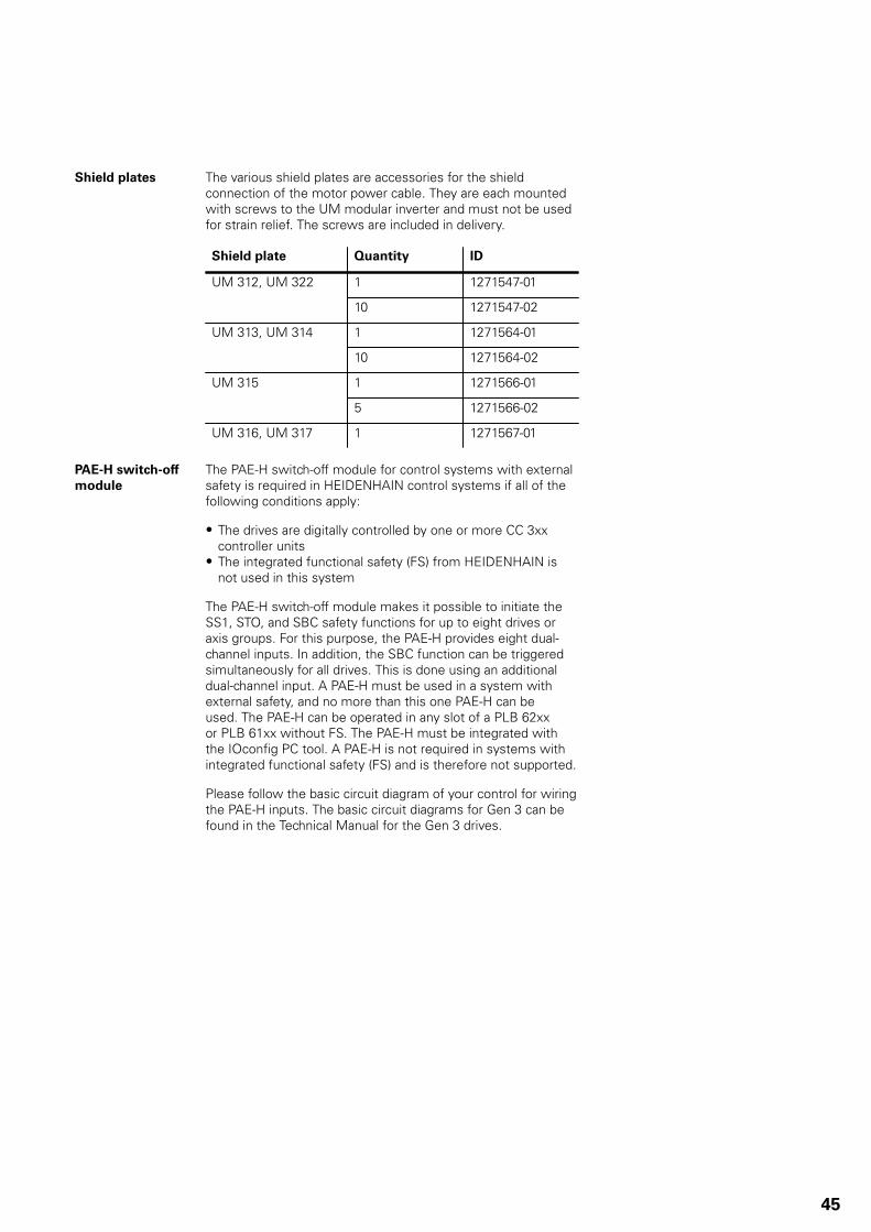
Shield plates The various shield plates are accessories for the shieldconnection of the motor power cable. They are each mountedwith screws to the UM modular inverter and must not be usedfor strain relief. The screws are included in delivery.
Shield plate Quantity ID
1 1271547-01UM 312, UM 322
10 1271547-02
1 1271564-01UM 313, UM 314
10 1271564-02
1 1271566-01UM 315
5 1271566-02
UM 316, UM 317 1 1271567-01
PAE-H switch-offmodule
The PAE-H switch-off module for control systems with externalsafety is required in HEIDENHAIN control systems if all of thefollowing conditions apply:
• The drives are digitally controlled by one or more CC 3xxcontroller units
• The integrated functional safety (FS) from HEIDENHAIN isnot used in this system
The PAE-H switch-off module makes it possible to initiate theSS1, STO, and SBC safety functions for up to eight drives oraxis groups. For this purpose, the PAE-H provides eight dual-channel inputs. In addition, the SBC function can be triggeredsimultaneously for all drives. This is done using an additionaldual-channel input. A PAE-H must be used in a system withexternal safety, and no more than this one PAE-H can beused. The PAE-H can be operated in any slot of a PLB 62xxor PLB 61xx without FS. The PAE-H must be integrated withthe IOconfig PC tool. A PAE-H is not required in systems withintegrated functional safety (FS) and is therefore not supported.
Please follow the basic circuit diagram of your control for wiringthe PAE-H inputs. The basic circuit diagrams for Gen 3 can befound in the Technical Manual for the Gen 3 drives.
45

HSCI connection With the Gen 3 drives, communication between the HSCIcomponents is carried out over Gbit cables with gray HSCIconnectors. Previous HSCI cables have black connectors.
The Gbit HSCI cable with ID 1257765-xx can also be used inplace of the HSCI cable for 100 Mbit (ID 618893-xx). However,the reverse is not possible. Control systems that require GbitHSCI can be operated only with the Gbit HSCI cable. The HSCIcables from HEIDENHAIN are suitable for use in drag chains.
HSCI cable ID Min. bendradius (rigidconfiguration)
Min. bendradius(frequentflexing,30000cycles)
Cablediameter
Max.cablelength
HSCI
618893-xx ≥ 40 mm ≥ 100 mm 6.8 mm 70 m 100MBit
1257765-xx ≥ 40 mm ≥ 100 mm 7.2 mm 15 m GBit
≥ 60 mm ≥ 150 mm 9.6 70 m GBit1306923-xx
Two short connecting pieces with thespecifications of ID 1257765-xx are includedin each delivery.
Cable lengths Description ID
Gbit HSCI cable: 0.20 m 1257765-A2
Gbit HSCI cable: 0.30 m 1257765-A3
Gbit HSCI cable: 0.50 m 1257765-A5
Gbit HSCI cable: 1.00 m 1257765-01
Gbit HSCI cable: 2.00 m 1257765-02
Gbit HSCI cable: 3.00 m 1257765-03
Gbit HSCI cable: 4.00 m 1257765-04
Gbit HSCI cable: 6.00 m 1257765-06
Gbit HSCI cable: 7.00 m 1257765-07
Gbit HSCI cable: 8.00 m 1257765-08
Gbit HSCI cable: 9.00 m 1257765-09
Gbit HSCI cable: 10.00 m 1257765-10
Gbit HSCI cable: 12.00 m 1257765-12
Gbit HSCI cable: 15.00 m 1257765-15
46

Kit lengths Kit ID
17 m 1306923-17
20 m 1306923-20
25 m 1306923-25
30 m 1306923-30
40 m 1306923-40
50 m 1306923-50
60 m 1306923-60
70 m 1306923-70
The kits (ID 1306923-xx) consist of:
• Two 20 cm long connecting pieces (specifications identical toID 1257765-xx) comprising:– One standard HSCI connector for connection to
HSCI components– One Gbit HSCI cable, 7.2 mm in diameter– One special coupling for connection to
Gbit HSCI cable for lines 17 m or longer (diameter: 9.6 mm)• One x Gbit HSCI cable, 9.6 mm in diameter (specifications
to identical ID 1306923-xx), 17 m to 70 m in length, with twospecial couplings for connection to the connecting piece
47

HFL(optical fiber)
The HFL lets you connect the UM 3xx modular inverters to theCC 3xx controller units for PWM-control of the inverters.
Length of the HFL cable
For the length of the optical fiber cable from the CC 3xxcontroller unit to the UM 3xx power module, HEIDENHAINrecommends the following:
When the UM 3xx power module is located to the left ofthe CC 3xx controller unit:
Length of optical fiber cable = Width of the module to beconnected (b) + Width of all modules (b) between the UM andthe CC + 300 mm (c1)
For example, the following arrangement: UVR 340, UM 314, UM 313, UM 322, UM 321, CC 308
CC 308 to UM 314: 650 mmCC 308 to UM 313: 550 mmCC 308 to UM 322: 450 mmCC 308 to UM 321: 350 mm
48

When the UM 3xx power module is located to the right ofthe CC 3xx controller unit:
Length of optical fiber cable = Width of the module to beconnected (b) + Width of all modules (b) between the UM andthe CC + 200 mm (c2)
For example, the following arrangement:UVR 340, UM 314, UM 313, CC 308, UM 321, UM 322
bc2c1b
CC 308 to UM 314: 500 mmCC 308 to UM 313: 400 mmCC 308 to UM 321: 300 mmCC 308 to UM 322: 350 mm
49

Orderablevariants of the HFLconnection
Rolls of optical fiber cable ID number
10 m roll of optical fiber cable, forassembly by the machine manufacturer
1265351-90
50 m roll of optical fiber cable, forassembly by the machine manufacturer
1265351-92
100 m roll of optical fiber cable, forassembly by the machine manufacturer
1265351-95
Cutting the optical fiber cable to length requires the followingtool:
• Rennsteig pliers for "cutting and stripping duplex cable" (ordernumber 8002 0012 3, available on request from HoffmannWerkzeuge)
• Replacement cutting tools for these pliers, also available fromHoffmann Werkzeuge with order number 8000 0005 0 0(safety cutting device, must be replaced after 2500 cuts)
Optical fiber cable cut tolength
ID number
0.30 m optical fiber cable 1265351-01
0.35 m optical fiber cable 1265351-02
0.40 m optical fiber cable 1265351-03
0.45 m optical fiber cable 1265351-04
0.50 m optical fiber cable 1265351-05
0.55 m optical fiber cable 1265351-06
0.60 m optical fiber cable 1265351-07
0.65 m optical fiber cable 1265351-08
0.70 m optical fiber cable 1265351-09
0.75 m optical fiber cable 1265351-10
0.80 m optical fiber cable 1265351-11
0.85 m optical fiber cable 1265351-12
0.90 m optical fiber cable 1265351-13
0.95 m optical fiber cable 1265351-14
1.00 m optical fiber cable 1265351-15
1.10 m optical fiber cable 1265351-17
1.20 m optical fiber cable 1265351-19
1.30 m optical fiber cable 1265351-21
1.40 m optical fiber cable 1265351-23
1.50 m optical fiber cable 1265351-25
1.60 m optical fiber cable 1265351-27
1.70 m optical fiber cable 1265351-29
1.80 m optical fiber cable 1265351-31
1.90 m optical fiber cable 1265351-33
2.00 m optical fiber cable 1265351-35
50

Overview of cablesInverters
UM 3xx UM 3xx UM 3xx UM 3xxUM3xx
UP3xx
CMH3xx
UVR 3xx
L1 L2 L3
KDR 3xx
18.12.2019
CC 3xx
Line filterEpcos
xxA
ID 1265351-xx
For power cables to the motor, see “HEIDENHAIN Motors” brochure.
DC-link and 24 V supply conductor-bar connection (included in delivery)
SIEMENS Sitor gS or gR line fuse
Optional overvoltage protector
For maximum lengths, see “Gen 3 Drives” Technical Manual.
51

Inverters (multi-row)
UM 3xx UM 3xx UM 3xxUP3xx
CMH3xx
UVR 3xx
L1 L2 L3
KDR 3xx
18.12.2019
CC 3xx UM 3xxUM3xx
UM 3xx
ID 1274603-xx
ID 1278910-xxLine filterEpcos
xxA
ID 1265351-xx
For power cables to the motor, see “HEIDENHAIN Motors” brochure.
DC-link and 24 V supply conductor-bar connection (included in delivery)
SIEMENS Sitor gS or gR line fuse
Optional overvoltage protector
For maximum lengths, see “Gen 3 Drives” Technical Manual.
RDBU
52

Mounting information
Mountingposition
Please note the following when mounting the HEIDENHAINpower modules:• The HEIDENHAIN power modules and control components
must be operated in enclosures or electrical cabinets thatfulfill at least an IP54 rating in accordance with the Europeanenclosure specifications. Ensure that, depending on thelocation of the machine, at least equivalent requirements arefulfilled. The machine manufacturer is responsible for this.
• The HEIDENHAIN power modules and control componentsmust be mounted vertically in the electrical cabinet.
• Minimum clearances that must be maintained• Required clearances for air circulation and servicing• Appropriate length of the cables• Permissible bending radii of the cables• Do not mount any other devices that generate or dissipate heat
below or in the immediate vicinity of the HEIDENHAIN powermodules. Air that has already been heated should be preventedfrom being sucked in for the cooling of the HEIDENHAIN powermodules.
• Professional mounting in connection with other devices in theelectrical cabinet (see the following drawings).
• All of the HEIDENHAIN control components or devices (CC,MC, BF, MB, TE, UV(R), UR, UE, UEC, UMC, KDR, SM, etc.)must be operated in enclosures suitable for this purpose, suchas electrical cabinets or panels. Fire protection enclosures inaccordance with the fire safety regulations must be used at thesite of installation. The enclosures must also provide protectionagainst electric shock.
Arrangement ofHEIDENHAINcomponents
CC 3xxUM 3xxUVR 3xxCMH 3xxUP 3xx
CC 3xxUM 3xxUVR 3xxCMH 3xxUP 3xx
53

Clearances forHEIDENHAINcomponents
CC 3xxUM 3xxUVR 3xxCMH 3xxUP 3xx
Mountingand electricalinstallation
For mounting and the electrical connection, comply with thefollowing:• National regulations for low-voltage installations at the
operating site of the machine or components• National regulations regarding interference and noise
immunity at the operating site of the machine or components• National regulations regarding electrical safety and
operating conditions at the operating site of the machine orcomponents
• Specifications for the installation position• Specifications of the Technical Manual
Degrees ofprotection
The following components fulfill the requirements forprotection class IP54 (dust- and splash-proof protection):• Display unit (when properly installed)• Keyboard unit (when properly installed)• Machine operating panel (when properly installed)• Handwheel
All electric and electronic control components must be installedin an environment (e.g., electrical cabinet, enclosure) that fulfillsthe requirements of protection class IP54 (dust- and splash-proof protection) in order to fulfill the requirements of pollutiondegree 2. All components of the OEM operating panel must,like the HEIDENHAIN operating panel components, complywith protection class IP54.
54

Electromagneticcompatibility
During installation, pay special attention to the following factorswith regard to electromagnetic compatibility.
Intended place ofoperation
HEIDENHAIN power modules and their accessories complywith the following standards based on Directive 2014/30/EC:■ Interference as per EN 61800-3, category C3 (limit values for
PDS I ≤ 100 A) and EN 50370-1■ Noise immunity in accordance with EN 61800-3, second
environment, and EN 50370-2
Protect your equipment from interference by following therules and recommendations on EMC provided in the TechnicalManual for the Gen 3 drives. In particular, ensure that youfollow the protective measures regarding an EMC-compliantconfiguration.
Place ofoperation
The inverter systems and power modules from HEIDENHAINare intended for operation in industrial and mixed-use areas.The devices conform to EN 50370 (product-family standard formachine tools) and EN 61800-3, and fulfill the requirementsfor an industrial low-voltage supply network. The devicesare not intended to be used on a public low-voltage supplynetwork that supplies households. The devices may cause high-frequency interference.
The product conforms to category C3 as per EN 61800-3. Thisproduct can cause radio interference in residential areas. Thiswould require the operator to ensure that appropriate measuresare taken.
Installationaltitude
The maximum installation altitude for HEIDENHAIN powermodules and their accessories (UVR, UM, UEC, KDR, linefilters, etc.) with direct connection to the supply network is2000 m above sea level because the HEIDENHAIN powermodules and their accessories comply with overvoltagecategory III as per EN 61800-5-1 and UL 61800-5-1 at analtitude of up to 2000 m above sea level.
At an installation altitude of greater than 2000 m abovesea level up to a maximum permissible installation altitudeof 3000 m, HEIDENHAIN power modules, as well as thecontrol system, must be operated in a supply network thatcomplies with overvoltage category II as per EN 61800-5-1 andUL 61800-5-1. This can be attained, for example, by means ofan upstream isolating transformer.
Be aware of degraded performance due to current deratingwhen HEIDENHAIN power modules are installed at altitudes ofgreater than 1000 m above sea level. Interpolation is linear forcurrent derating:• 1000 m to 2000 m: 100% to 85%• 2000 m to 3000 m: 85% to 75%
55
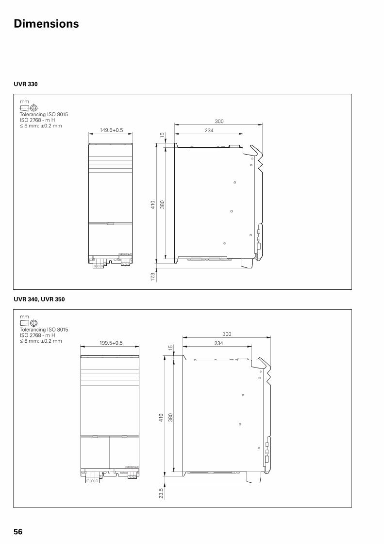
Dimensions
UVR 330
234149.5+0.5
300
410
17.3
380
15
UVR 340, UVR 350
234
300
410
380
15
199.5+0.5
23.5
56

UVR 360(W)
234
300
410
380
15
28
249.5+0.5
UVR 370(W)
234
300
410
380
15
35
249.5+0.5
57

UM 310, UM 311, UM 320, UM 321
23449.5+0.5
300
6341
0
380
15
UM 312, UM 322
23499.5+0.5
300
9.5
410
380
15
58

UM 313
23499.5+0.5
300
19.6
410
380
15
59

UM 314
23499.5+0.5
300
2841
0
380
15
60

Shield plate for UM 312, UM 322, UM 313, UM 314
61

UM 315
234149.75+0.5
300
410
35
380
15
62

UM 316
234
188
300
410
380
15
199.5+0.5
124.
5
63

UM 316W
234
188
300
410
380
15
199.5+0.5
124.
5
64

UM 317W
234
188
300
410
380
15
199.5+0.5
124.
5
65

Shield plate UM 315, UM 316, UM 317
0
19
0.5
10.50.3
44.5
0.5
57.5
0.5
69
0.5
83
0.5
107.
50.
5
113
0.5
2
2
UM 315
1140.2
1281
100.5
14
7
0
15150
1
192
2
0
38.5
0.5
63.5
0.5
88.5
0.5
113.
50.
5
16
0.5
20
0.5 75
1
110
2
140
120
0.5
40.5
60.5
UM 316 / UM 317
1541
1362 67.9
76.9
104.
9
8
5
20
66

CC 302
23449.5+0.5
300
410
380
15
CC 306
23474.5+0.5
300
410
380
15
67

CC 308
23499.5+0.5
300
410
380
15
CC 310
234124.5+0.5
300
410
380
15
68

CMH 320, UP 310, UP 320
23449.5+0.5
300
410
380
15
KDR 330
160
76 90
6.5
30.5
21.5
60.2
~44
10.3
200.
1
150
200
69

KDR 340
1601
801 801
28.5
2422
120
1
119.
53
225
5
8.1
4x
801 801
164528.5
70

KDR 350
1601
75
801 801
28.5
2502
120
1
119.
53
225
5
8.14x
801 801
164528.5
1715
71

KDR 360
2501
150
1
3582
129.52
291
5
178
2 (89)
(89)
9
6x
72

KDR 370
2501
150
1
3582
129.52
373
5
418
517
82 (8
9)(8
9)
9
6x
73

Line filter 46A
238
M6x24
233
4265
1
70
0.2
2100.3
195
220
65
142
1.5
94100
5.5
170
45
50
Line filter 83A
303
297.6
4248
.7
48.7
42
1.5
260
290
85110
116
7
M6x25
25
150
57.8
2800.3
74

Line filter 135A
386
5451
.5
51.5
54
1.5
M8x28.5
65
25
150
335
300
100
0.4
125
130
6.5
3151
Line filter 202A
501
9974 74
99
1.5
438
400
4130.8
100
0.5
145
150 6.
5
M8x28.5
75
60
210
75

SM 320
180.5
0.2
6.5
13
188.5
200.5
454
19.5
49.25
82.25
115.25
0
46.5
5514
9
100
66.2
56.
5
50
0.2
49.7
5
9
98
U
V
W
76

SM 330
170
13.5
0.26.
5
6.5
R6.5
35
100
0.2
170
10
103.25
110
0
35
73.35
109.35
145.35
U
W
V
77

Subject index
A
Accessories for coolant connection.................................................................................................................................................. 39Accessories for inverter systems...................................................................................................................................................... 36Accessories for the UVR 3xx power supply units............................................................................................................................ 22
B
Braking resistor.................................................................................................................................................................................. 38
C
CC 302........................................................................................................................................................................................ 35, 67CC 306........................................................................................................................................................................................ 35, 67CC 308........................................................................................................................................................................................ 35, 68CC 310......................................................................................................................................................................................... 35, 68CMH 320..................................................................................................................................................................................... 43, 69Controller unit.................................................................................................................................................................................... 34
D
DC-link voltage..................................................................................................................................................................................... 5Dimensions........................................................................................................................................................................................ 56
E
EPCOS 135A...................................................................................................................................................................................... 37EPCOS 202A..................................................................................................................................................................................... 37EPCOS 46A....................................................................................................................................................................................... 37EPCOS 83A....................................................................................................................................................................................... 37
F
Functional safety (FS).......................................................................................................................................................................... 6
H
HFL cable and bus mounting.............................................................................................................................................................. 7
I
Inverter systems................................................................................................................................................................................ 11
K
KDR 330...................................................................................................................................................................................... 36, 69KDR 340...................................................................................................................................................................................... 36, 70KDR 350...................................................................................................................................................................................... 36, 71KDR 360...................................................................................................................................................................................... 37, 72KDR 370...................................................................................................................................................................................... 37, 73KDR 3xx commutating reactor.......................................................................................................................................................... 36
L
Line filter............................................................................................................................................................................................ 37Line filter 135 A................................................................................................................................................................................. 75Line filter 202 A................................................................................................................................................................................ 75Line filter 46 A.................................................................................................................................................................................. 74Line filter 83 A.................................................................................................................................................................................. 74
78

M
Modular inverters.......................................................................................................................................................................... 6, 23Modular inverter systems.................................................................................................................................................................... 8Motor currents..................................................................................................................................................................................... 7Mounting information........................................................................................................................................................................ 53Mounting position.............................................................................................................................................................................. 53Multi-row configuration...................................................................................................................................................................... 44
N
Non-regenerative inverter systems..................................................................................................................................................... 4
O
Output currents................................................................................................................................................................................. 28Overview of cables............................................................................................................................................................................ 51
P
PAE-H switch-off module................................................................................................................................................................... 45Power supply unit.............................................................................................................................................................................. 18
R
Regenerative inverter systems............................................................................................................................................................ 4
S
Safety functions................................................................................................................................................................................... 5SM 320.............................................................................................................................................................................................. 76SM 330.............................................................................................................................................................................................. 77SM voltage protection module.......................................................................................................................................................... 41Surge protectors................................................................................................................................................................................ 40
U
UM 310....................................................................................................................................................................................... 24, 58UM 311........................................................................................................................................................................................ 24, 58UM 312....................................................................................................................................................................................... 24, 58UM 313....................................................................................................................................................................................... 25, 59UM 314....................................................................................................................................................................................... 25, 60UM 315....................................................................................................................................................................................... 25, 62UM 316....................................................................................................................................................................................... 26, 63UM 316 W.................................................................................................................................................................................. 26, 64UM 317 W.................................................................................................................................................................................. 26, 65UM 320....................................................................................................................................................................................... 27, 58UM 321....................................................................................................................................................................................... 27, 58UM 322....................................................................................................................................................................................... 27, 58UM 3xx, accessories......................................................................................................................................................................... 33UM 3xx, currents........................................................................................................................................................................ 28, 29UM 3xx load cycles........................................................................................................................................................................... 31UP 310............................................................................................................................................................................................... 69UP 320............................................................................................................................................................................................... 69UVR 330............................................................................................................................................................................................ 56UVR 340............................................................................................................................................................................................ 56UVR 350............................................................................................................................................................................................ 56UVR 360 (W)..................................................................................................................................................................................... 57UVR 370 (W)..................................................................................................................................................................................... 57UVR load cycles................................................................................................................................................................................. 21
79

PL APS02-384 Warszawa, Poland www.heidenhain.pl
PT FARRESA ELECTRÓNICA, LDA.4470 - 177 Maia, Portugal www.farresa.pt
RO HEIDENHAIN Reprezentanta RomaniaBrasov, 500407, Romania www.heidenhain.ro
RS Serbia BG
RU OOO HEIDENHAIN115172 Moscow, Russia www.heidenhain.ru
SE HEIDENHAIN Scandinavia AB12739 Skärholmen, Sweden www.heidenhain.se
SG HEIDENHAIN PACIFIC PTE LTDSingapore 408593 www.heidenhain.com.sg
SK KOPRETINA TN s.r.o.91101 Trencin, Slovakia www.kopretina.sk
SL NAVO d.o.o.2000 Maribor, Slovenia www.heidenhain.si
TH HEIDENHAIN (THAILAND) LTDBangkok 10250, Thailand www.heidenhain.co.th
TR T&M Mühendislik San. ve Tic. LTD. STI·.
34775 Y. Dudullu – Ümraniye-Istanbul, Turkey www.heidenhain.com.tr
TW HEIDENHAIN Co., Ltd.Taichung 40768, Taiwan R.O.C. www.heidenhain.com.tw
UA Gertner Service GmbH Büro Kiev 02094 Kiev, Ukraine www.heidenhain.ua
US HEIDENHAIN CORPORATIONSchaumburg, IL 60173-5337, USA www.heidenhain.com
VN AMS Co. LtdHCM City, VietnamE-mail: [email protected]
ZA MAFEMA SALES SERVICES C.C.Kyalami 1684, South Africa www.heidenhain.co.za
ES FARRESA ELECTRONICA S.A.08028 Barcelona, Spain www.farresa.es
FI HEIDENHAIN Scandinavia AB01740 Vantaa, Finland www.heidenhain.fi
FR HEIDENHAIN FRANCE sarl92310 Sèvres, France www.heidenhain.fr
GB HEIDENHAIN (G.B.) LimitedBurgess Hill RH15 9RD, United Kingdom www.heidenhain.co.uk
GR MB Milionis Vassilis17341 Athens, Greece www.heidenhain.gr
HR Croatia SL
HU HEIDENHAIN Kereskedelmi Képviselet1239 Budapest, Hungary www.heidenhain.hu
ID PT Servitama Era ToolsindoJakarta 13930, Indonesia E-mail: [email protected]
IL NEUMO VARGUS MARKETING LTD.Holon, 58859, Israel E-mail: [email protected]
IN HEIDENHAIN Optics & Electronics India Private LimitedChetpet, Chennai 600 031, India www.heidenhain.in
IT HEIDENHAIN ITALIANA S.r.l.20128 Milano, Italy www.heidenhain.it
JP HEIDENHAIN K.K.Tokyo 102-0083, Japan www.heidenhain.co.jp
KR HEIDENHAIN Korea Ltd.Anyang-si, Gyeonggi-do, 14087 South Korea www.heidenhain.co.kr
MX HEIDENHAIN CORPORATION MEXICO20290 Aguascalientes, AGS., Mexico E-mail: [email protected]
MY ISOSERVE SDN. BHD.43200 Balakong, Selangor E-mail: [email protected]
NL HEIDENHAIN NEDERLAND B.V.6716 BM Ede, Netherlands www.heidenhain.nl
NO HEIDENHAIN Scandinavia AB7300 Orkanger, Norway www.heidenhain.no
NZ Llama ENGINEERING Ltd5012 Wellington, New Zealand E-mail: [email protected]
PH MACHINEBANKS' CORPORATIONQuezon City, Philippines 1113 E-mail: [email protected]
AR NAKASE SRL.B1653AOX Villa Ballester, Argentina www.heidenhain.com.ar
AT HEIDENHAIN Techn. Büro Österreich83301 Traunreut, Germany www.heidenhain.de
AU FCR MOTION TECHNOLOGY PTY LTDLaverton North Victoria 3026, Australia E-mail: [email protected]
BE HEIDENHAIN NV1760 Roosdaal, Belgium www.heidenhain.be
BG ESD Bulgaria Ltd.Sofia 1172, Bulgaria www.esd.bg
BR HEIDENHAIN Brasil Ltda.04763-070 – São Paulo – SP, Brazil www.heidenhain.com.br
BY GERTNER Service GmbH220026 Minsk, Belarus www.heidenhain.by
CA HEIDENHAIN CORPORATIONMississauga, OntarioL5T2N2, Canada www.heidenhain.com
CH HEIDENHAIN (SCHWEIZ) AG8603 Schwerzenbach, Switzerland www.heidenhain.ch
CN DR. JOHANNES HEIDENHAIN (CHINA) Co., Ltd.Beijing 101312, China www.heidenhain.com.cn
CZ HEIDENHAIN s.r.o.102 00 Praha 10, Czech Republic www.heidenhain.cz
DK TP TEKNIK A/S2670 Greve, Denmark www.tp-gruppen.dk
DE HEIDENHAIN Vertrieb Deutschland83301 Traunreut, Deutschland 08669 31-3132| 08669 32-3132E-Mail: [email protected]
HEIDENHAIN Technisches Büro Nord12681 Berlin, Deutschland 030 54705-240
HEIDENHAIN Technisches Büro Mitte07751 Jena, Deutschland 03641 4728-250
HEIDENHAIN Technisches Büro West44379 Dortmund, Deutschland 0231 618083-0
HEIDENHAIN Technisches Büro Südwest70771 Leinfelden-Echterdingen, Deutschland 0711 993395-0
HEIDENHAIN Technisches Büro Südost83301 Traunreut, Deutschland 08669 31-1337
Vollständige und weitere Adressen siehe www.heidenhain.de For complete and further addresses see www.heidenhain.de
����������������������������������������������������������� ���� ���������������� ����������� ��������� �����������������������������
����������������
1303180-21 · 2 · 03/2020 · H · Printed in Germany