Gemini Photo Digitizer v.X9 - User Manualgeminicad.net/download/Gemini_manuals/Gemini_Photo... ·...
65
User manual - Gemini Photo Digitizer Plan 1 Gemini Cad Systems www.geminicad.com Gemini Photo Digitizer User manual rev VX9 Gemini Photo Digitizer is part of the Gemini CAD package, that contains the following applications: Gemini Pattern Editor Gemini Photo Digitizer Gemini Cut Plan Gemini Nest Expert Gemini PLT Spooler © 2010 Venus Technologies Provider ITN 0051 rev 01.2010
Transcript of Gemini Photo Digitizer v.X9 - User Manualgeminicad.net/download/Gemini_manuals/Gemini_Photo... ·...
User manual - Gemini Photo Digitizer Plan
1
Gemini Cad Systems www.geminicad.com
Gemini Photo Digitizer
User manual rev VX9 Gemini Photo Digitizer is part of the Gemini CAD package, that contains the following applications: Gemini Pattern Editor Gemini Photo Digitizer Gemini Cut Plan Gemini Nest Expert Gemini PLT Spooler © 2010 Venus Technologies Provider ITN 0051 rev 01.2010

User manual - Gemini Photo Digitizer Plan
2
User manual - Gemini Photo Digitizer Plan
3
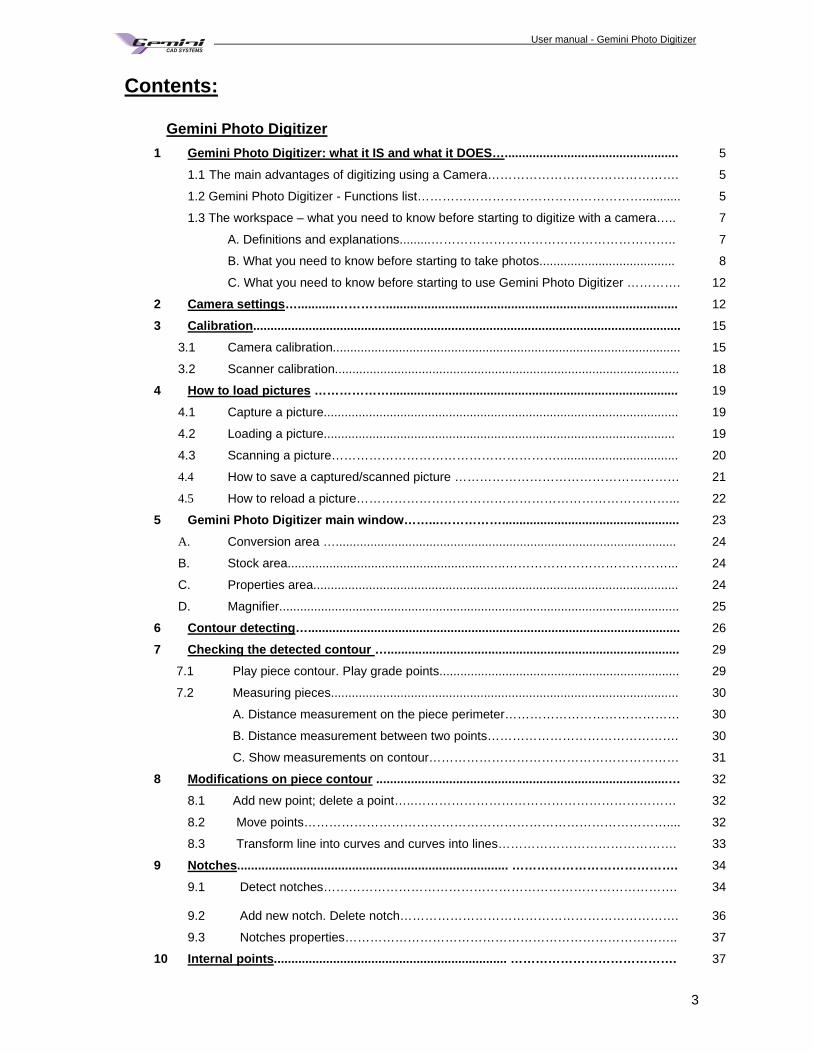
Contents: Gemini Photo Digitizer
1 Gemini Photo Digitizer: what it IS and what it DOES… .................................................. 5
1.1 The main advantages of digitizing using a Camera………………………………………. 5
1.2 Gemini Photo Digitizer - Functions list………………………………………………........... 5
1.3 The workspace – what you need to know before starting to digitize with a camera….. 7
A. Definitions and explanations.........………………………………………………….. 7
B. What you need to know before starting to take photos....................................... 8
C. What you need to know before starting to use Gemini Photo Digitizer …………. 12
2 Camera settings …...........………….................................................................................... 12
3 Calibration ........................................................................................................................... 15
3.1 Camera calibration.................................................................................................... 15
3.2 Scanner calibration................................................................................................... 18
4 How to load pictures ………………................................................................................... 19
4.1 Capture a picture...................................................................................................... 19
4.2 Loading a picture..................................................................................................... 19
4.3 Scanning a picture………………………………………………................................... 20
4.4 How to save a captured/scanned picture ……………………………………………… 21
4.5 How to reload a picture…………………………………………………………………... 22
5 Gemini Photo Digitizer main window……...……………....... ............................................ 23
A. Conversion area ….................................................................................................. 24
B. Stock area.........................................................…..…………………………………... 24
C. Properties area......................................................................................................... 24
D. Magnifier................................................................................................................... 25
6 Contour detecting …........................................................................................................... 26
7 Checking the detected contour ….................................................................................... 29
7.1 Play piece contour. Play grade points..................................................................... 29
7.2 Measuring pieces.................................................................................................... 30
A. Distance measurement on the piece perimeter…………………………………… 30
B. Distance measurement between two points………………………………………. 30
C. Show measurements on contour…………………………………………………… 31
8 Modifications on piece contour ....................................................................................… 32
8.1 Add new point; delete a point…..……………………………………………………… 32
8.2 Move points…………………………………………………………………………….... 32
8.3 Transform line into curves and curves into lines……………………………………. 33
9 Notches .............................................................................. …………………………………. 34
9.1 Detect notches………………………………………………………………………….
34
9.2 Add new notch. Delete notch…………………………………………………………. 36
9.3 Notches properties…………………………………………………………………….. 37
10 Internal points ................................................................... …………………………………. 37
User manual - Gemini Photo Digitizer Plan
4
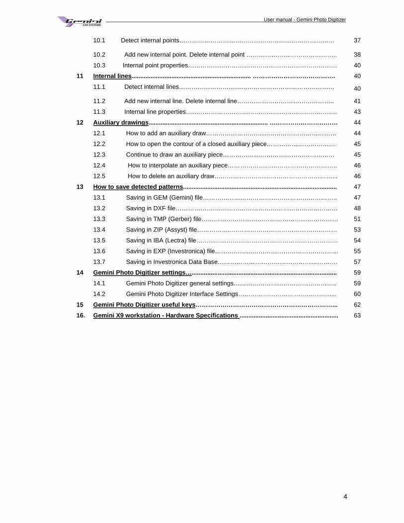
10.1 Detect internal points…………………………………………………………………
37
10.2 Add new internal point. Delete internal point …………………………………….. 38
10.3 Internal point properties……………………………………………………………… 40
11 Internal lines ..................................................................... …………………………………. 40
11.1 Detect internal lines…………………………………………………………………
40
11.2 Add new internal line. Delete internal line……………………………………….. 41
11.3 Internal line properties………………………………………………………………. 43
12 Auxiliary drawings ..................................................................... …………………………… 44
12.1 How to add an auxiliary draw……………………………………………………… 44
12.2 How to open the contour of a closed auxiliary piece…………………………… 45
12.3 Continue to draw an auxiliary piece……………………………………………… 45
12.4 How to interpolate an auxiliary piece…………………………………………….. 46
12.5 How to delete an auxiliary draw…………………………………………………... 46
13 How to save detected patterns ......................................................................................... 47
13.1 Saving in GEM (Gemini) file……………………………………………………….. 47
13.2 Saving in DXF file………………….………………………………………...……… 48
13.3 Saving in TMP (Gerber) file………………………………………………………… 51
13.4 Saving in ZIP (Assyst) file……………..…………………………………………… 53
13.5 Saving in IBA (Lectra) file……...…………………………………………………… 54
13.6 Saving in EXP (Investronica) file…………………………………………………... 55
13.7 Saving in Investronica Data Base…………………………………………………. 57
14 Gemini Photo Digitizer settings… .................................................................................... 59
14.1 Gemini Photo Digitizer general settings………………………………………….. 59
14.2 Gemini Photo Digitizer Interface Settings………………………………………... 60
15 Gemini Photo Digitizer useful keys …………………………………………………………... 62
16. Gemini X9 workstation - Hardware Specifications ......................................................... 63
User manual - Gemini Photo Digitizer Plan
5
Gemini Photo Digitizer 1. Gemini Photo Digitizer: what it IS and what it D OES « Gemini Photo Digitizer» application is a tool that helps you to convert the printed or paper patterns into an
electronic form. For this you will need a photo camera and a contrast surface. The camera is connected to a computer where Gemini Photo Digitizer is installed. After you capture the picture
the application converts image in geometrical shapes, and technical elements.
1.1 The main advantages of digitizing usi ng a Camera
There are three main advantages resulting from digitizing with a camera - The pattern can be converted very quickly in electronic format because the user will just take a picture and he will no longer cover all pieces shapes and technical elements. The conversion will be make automatically by Gemini Photo Digitizer. For example: it will takes at list 30 minutes to use a digitizer for a model with 7 pieces and only few seconds to digitize with a camera or scanner. - If you will use a camera than you will earn the entire space necessary for a classic digitizer - The geometrical shapes of the patterns can be saved in many file formats: as *.GEM, DXF, TMP, Assyst ZIP, EXP, IBA. Because of this, the digitized patterns can be loaded in very different CAD systems.
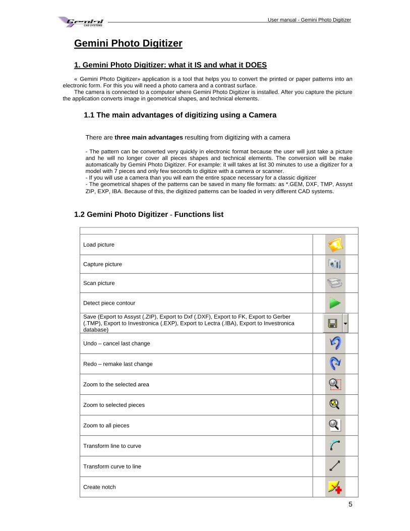
1.2 Gemini Photo Digitizer - Functions list
Load picture
Capture picture
Scan picture
Detect piece contour
Save (Export to Assyst (.ZIP), Export to Dxf (.DXF), Export to FK, Export to Gerber (.TMP), Export to Investronica (.EXP), Export to Lectra (.IBA), Export to Investronica database)
Undo – cancel last change
Redo – remake last change
Zoom to the selected area
Zoom to selected pieces
Zoom to all pieces
Transform line to curve
Transform curve to line
Create notch
User manual - Gemini Photo Digitizer Plan
6
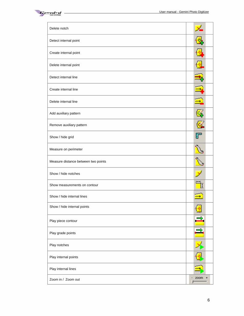
Delete notch
Detect internal point
Create internal point
Delete internal point
Detect internal line
Create internal line
Delete internal line
Add auxiliary pattern
Remove auxiliary pattern
Show / hide grid
Measure on perimeter
Measure distance between two points
Show / hide notches
Show measurements on contour
Show / hide internal lines
Show / hide internal points
Play piece contour
Play grade points
Play notches
Play internal points
Play internal lines
Zoom in / Zoom out
User manual - Gemini Photo Digitizer Plan
7
1.3 The workspace – what you need to know before st arting to digitize with a camera A. Definitions and explanations
To understand and master the Gemini Photo Digitizer functions we must clearly define end explain the technical terms.
Picture A picture represents photography of some patterns made with a camera or a scanner. Picture resolution Resolution refers to the number of pixels in an image. Resolution is sometimes identified by the width and
height of the image as well as the total number of pixels in the image. For example, an image that is 2048 pixels wide and 1536 pixels high (2048X1536) contains (multiply) 3,145,728 pixels (or 3.1 Megapixels). You could call it a 2048X1536 or a 3.1 Megapixel image. As the megapixels in the pickup device in your camera increase so does the possible maximum size image you can produce. This means that a 5 megapixel camera is capable of capturing a larger image than a 3 megapixel camera.
Sensor Size Sensor size determines how much noise a sensor produces, and noise is one of the main limitations on the
performance of a digital camera. Noise in a digital image is manifested as speckles all over. It is recommended to use camera with Sensor Size” between 1 / 2.5” and 1 / 1.6”. Camera Exposure Exposure is the amount of light which falls upon the sensor of a digital camera. Shutter speed and aperture are
adjusted to achieve optimal exposure of a scene. Most digital cameras offer a variety of exposure modes from fully-automatic to semi-automatic to full manual mode.
Camera ISO ISO is the number indicating a digital camera sensors sensitivity to light. The higher the sensitivity, the less
light is needed to make an exposure. Shooting at a lower ISO number requires more light than shooting at a higher number. Lower numbers result in images with the least visible noise, which is desirable.
Camera flash Many digital cameras have several flash modes to choose from. A built-in flash is small and not very
powerful so whichever mode you use, make sure to stay within the specified flash range. Camera zoom A digital camera, usually, can make two types of zoom: Optical zoom and Digital zoom. Optical zoom Optical zoom magnifies the size of an image by adjusting the lens. Unlike digital zoom, optical zoom enlarges
the subject without sacrificing resolution. All cameras have something called a focal length. This is true even for a camera without a zoom lens. The
focal length is the distance from the optical center of the lens to the camera's focal point. For digital cameras the focal point is located on the camera's sensor. The position of the lens changes as you zoom in and out. As you zoom in the focal length increases. As you zoom out the focal length decreases.
Digital zoom Digital zoom is completely different to optical zoom. Rather than using the lens to zoom, digital zoom is carried
out by software inside the camera. Concisely the software enlarges part of the image to give the impression of zooming in. An element of guesswork is involved in the process and leads to a decrease in quality. Therefore optical zoom is considered far superior to digital zoom.
It is not recommended to use digital zoom when you capture pictures for digitizing. Piece A piece is a detected contour with a specific shape and technical elements as: notches, grain axis, text axes,
internal points, piece name. The piece contour is formed by points with specific coordinates; the points are connected by lines and curves.
User manual - Gemini Photo Digitizer Plan
8
Points Multiple points connected by lines and/or curves form a piece contour. The points can be corners or can be
located on curves and lines. Each point has two coordinates, on horizontal and on vertical from the piece origin point. Piece origin can be any point on the contour and can be reallocated without any contour shape changes.
To modify a piece shape you can change the point type and position, you can add or delete points or you can change the curve shapes. There are two types of points: graded points and curve points.
Corners The points from piece contour can be cusp or can be smooth.
On the smooth point, there is a single tangent. This tangent has two control points whose movements are symmetrical. For a cusp point, the control tangents are mutually independent as angle or length.
The user can set the type of point that will correspond to a corner, a grade point or a curve point. All the time a corner point will be a cusp point. Even if the user set the corners as curve points, this points will
not be interpolated and will remain cusp. Bezier curve; Control points; End points Lines and curves connect the contour points. Gemini Photo Digitizer uses a special curve type named
« Bezier curve » from the French mathematician that invented them. A Bezier curve is a curve between two points whose shape can be adjusted by moving two control points.
Bezier curves may reproduce accurately the natural and anatomical shapes, being very useful for pattern contours tracing. All you need to know about Bezier curves is that they are defined by 4 points: 2 end points and 2 control points; moving these points are modifying the curve shape.
B. What you need to know before starting to take photos Choosing the photo camera
It is recommended to use a camera with a big Sensor Resolution (between 6 and 10 Mega Pixels). For 6 MP, using an aspect ratio of 4:3 (2832 X 2128 pixels), on a photo area of 1metter per 0.75 meters, 1
pixel will represent 0.35mm For 6 MP, using an aspect ratio of 3:2 (3000 X 2000 pixels), on a photo area of 1metter per 0.67 meters, 1
pixel will represent 0.33mm In addition, if it will be used a camera with a bigger sensor resolution, the conversion of picture will be done
with more accuracy because 1 pixel will represent a smaller surface. The minimal recommended picture resolution is that one where 1 pixel don’t has more than 0.4mm. In this
case, a camera of 10 MP it is recommended to take photo to a surface of maximum 1, 4 meters x 1 meter. It is recommended to use camera with Sensor Size” between 1 / 2.5” and 1 / 1.6”. To connect faster to the camera you can remove the memory card. The Gemini Photo Digitizer supported cameras are Canon cameras listed bellow:
PowerShot A10, PowerShot A20, PowerShot A30, PowerShot A40, PowerShot A60, PowerShot A70, PowerShot A75, PowerShot A80, PowerShot A85, PowerShot A95 PowerShot A100, PowerShot A200, PowerShot A300, PowerShot A310, PowerShot A400, PowerShot A510, PowerShot A520, PowerShot A620 PowerShot A640 PowerShot S1 IS, PowerShot S2 IS PowerShot S3 IS PowerShot S5 IS PowerShot S10, PowerShot S20, PowerShot S30, PowerShot S40, PowerShot S45, PowerShot S50, PowerShot S60,
User manual - Gemini Photo Digitizer Plan
9
PowerShot S70 PowerShot S80, PowerShot G1, PowerShot G2, PowerShot G3, PowerShot G5, PowerShot G6, PowerShot G7
PowerShot G9 PowerShot G10
PowerShot Pro90 IS, PowerShot Pro1 PowerShot S100, IXY DIGITAL, DIGITAL IXUS, PowerShot S110, IXY DIGITAL 200, DIGITAL IXUS v, PowerShot S200, IXY DIGITAL 200a, DIGITAL IXUS v2, PowerShot S230, IXY DIGITAL 320, DIGITAL IXUS v3, PowerShot S300, IXY DIGITAL 300, DIGITAL IXUS 300, PowerShot S400, IXY DIGITAL 400, DIGITAL IXUS 400, PowerShot S410, IXY DIGITAL 450, DIGITAL IXUS 430, PowerShot S500, IXY DIGITAL 500, DIGITAL IXUS 500, PowerShot SD100, IXY DIGITAL 30, DIGITAL IXUS II, PowerShot SD110, IXY DIGITAL 30a, DIGITAL IXUS IIs, PowerShot SX100 IS
PowerShot SX110 IS
EOS-1D Mark II EOS 20D EOS-1Ds Mark II EOS Kiss Digital N/350D/REBEL XT EOS 5D (EOS 5D cannot be used with Mac OS X 10.5.) EOS-1D Mark II N EOS 30D EOS Kiss Digital X/400D/REBEL XTi EOS-1D Mark III EOS 40D EOS-1Ds Mark III EOS DIGITAL REBEL Xsi/450D/ Kiss X2 EOS DIGITAL REBEL XS/ 1000D/ KISS F EOS 50D EOS 5D Mark II EOS Kiss X3/EOS REBEL T1i /EOS 500D
The Gemini Photo Digitizer supported cameras are Nikon cameras listed bellow: Nikon Coolpix L19 Nikon Coolpix L20 Nikon Coolpix L21 Nikon Coolpix L22 Nikon Coolpix S220 Nikon Coolpix L100 Nikon Coolpix S570
The supported cameras list will be bigger and you can download it from our site. You can use a camera, which is not in the supported cameras list, but this one has to have the recommended characteristics. In this case, the user will take photos on camera memory, will download them on PC and will load the pictures on Gemini Photo Digitizer. This will require more time than using a supported camera.
Camera position: Camera must be placed on a fixed position (use a tripod or any other type of support that will keep the camera
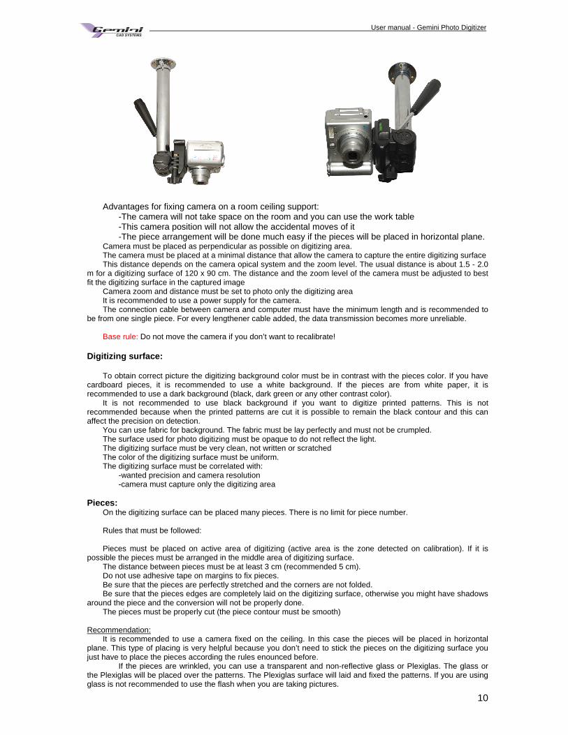
fixed) It is recommended to fix the camera on room ceiling, above the digitizing surface. But you must
carry on the conditions: keep minimum distance, use only optical zoom, and capture the entire digitizing surface).
User manual - Gemini Photo Digitizer Plan
10
Advantages for fixing camera on a room ceiling support: -The camera will not take space on the room and you can use the work table -This camera position will not allow the accidental moves of it -The piece arrangement will be done much easy if the pieces will be placed in horizontal plane. Camera must be placed as perpendicular as possible on digitizing area. The camera must be placed at a minimal distance that allow the camera to capture the entire digitizing surface This distance depends on the camera opical system and the zoom level. The usual distance is about 1.5 - 2.0
m for a digitizing surface of 120 x 90 cm. The distance and the zoom level of the camera must be adjusted to best fit the digitizing surface in the captured image
Camera zoom and distance must be set to photo only the digitizing area It is recommended to use a power supply for the camera. The connection cable between camera and computer must have the minimum length and is recommended to
be from one single piece. For every lengthener cable added, the data transmission becomes more unreliable. Base rule: Do not move the camera if you don’t want to recalibrate!
Digitizing surface:
To obtain correct picture the digitizing background color must be in contrast with the pieces color. If you have cardboard pieces, it is recommended to use a white background. If the pieces are from white paper, it is recommended to use a dark background (black, dark green or any other contrast color).
It is not recommended to use black background if you want to digitize printed patterns. This is not recommended because when the printed patterns are cut it is possible to remain the black contour and this can affect the precision on detection.
You can use fabric for background. The fabric must be lay perfectly and must not be crumpled. The surface used for photo digitizing must be opaque to do not reflect the light. The digitizing surface must be very clean, not written or scratched The color of the digitizing surface must be uniform. The digitizing surface must be correlated with: -wanted precision and camera resolution -camera must capture only the digitizing area
Pieces:
On the digitizing surface can be placed many pieces. There is no limit for piece number. Rules that must be followed: Pieces must be placed on active area of digitizing (active area is the zone detected on calibration). If it is
possible the pieces must be arranged in the middle area of digitizing surface. The distance between pieces must be at least 3 cm (recommended 5 cm). Do not use adhesive tape on margins to fix pieces. Be sure that the pieces are perfectly stretched and the corners are not folded. Be sure that the pieces edges are completely laid on the digitizing surface, otherwise you might have shadows
around the piece and the conversion will not be properly done. The pieces must be properly cut (the piece contour must be smooth)
Recommendation:
It is recommended to use a camera fixed on the ceiling. In this case the pieces will be placed in horizontal plane. This type of placing is very helpful because you don’t need to stick the pieces on the digitizing surface you just have to place the pieces according the rules enounced before.
If the pieces are wrinkled, you can use a transparent and non-reflective glass or Plexiglas. The glass or the Plexiglas will be placed over the patterns. The Plexiglas surface will laid and fixed the patterns. If you are using glass is not recommended to use the flash when you are taking pictures.
User manual - Gemini Photo Digitizer Plan
11
If you don't use this type of glass or Plexiglas you must use heavy weights to fix the pieces. The recommended weights must be small and should be placed on at list 2 cm from the edge of the pattern.
Do not use big and height objects to fix the patterns. You must be careful to the weights dimensions in order to avoid shadows.
For bigger accuracy on internal elements detection you must avoid to draw elements near the patterns edges and the text must be as short and as small as possible. Use patterns with fewer texts. Use pen less visible for the texts, for the internal drawings and the seam line.
The texts must be as small as possible and must be at list at 1 cm distance from the internal lines. For internal lines and internal points use black or blue pen for cardboard or white paper patterns. If the
patterns are from a different color than white than use a contrast color to mark the internal lines and points. You must avoid drawing internal lines till the pattern edges. The longer internal line will be detected as grain
axes. It is recommended to draw the internal line as it is possible in the middle of the pattern. If you will mark one end of the grain axes with a spot, that end will be interpreted on conversion as the direction of the grain axes.
How must be the internal points to be precise detected: -Two intersected lines of 1 or 1.5 cm length -the lines must be perpendicular on each other -the lines must be intersected in the middle How should appear the notches to be precise detected:
-One small line not to bolded -must have at list 0.5 or 1.5 cm in length
-must be drawn at the correct angle Luminosity
- For a good picture is recommended to use natural light - While using artificial light please ensure that the digitizing area is uniform lighted - When using other source than natural light be sure that the picture will not be too bright or too dark - If the intensity of light suffered substantial modifications, it is necessary to set again the camera exposure.
It is not necessary to recalibrate. Calibration
Calibration is the process of determining the relation between the picture and a standard measurement. It is
necessary the calibration because of the lens distortions. The most frequent distortion is barrel effect. Barrel distortion is a lens effect, which causes images to be spherical or "inflated". To calibrate it is necessary a grid or you can introduce a horizontally and vertically dimension for the picture. For a precise calibration, it is recommended to use a printed grid. So it is very important to not change the camera position after calibration because if you will change it you will
have different dimensions for pieces. Grid paper properties:
The grid must be printed on a white paper (as white as possible). The paper must have uniform color, without any type of drawings and without folds. It is recommended to use matt paper to not reflect the light.
The paper must have the length and the width bigger with 20% than estimated digitizing area. How to print the grid:
The grid must be printed on high quality printer. It is recommended to use inkjet plotter not plotter with pen. Use black color for grid, and ensure that the grid is not interrupted. The grid lines must be at list 2 mm width. The grid must have equal rectangles (recommended squares of 5 cm). It is not essential to have squares of 5
cm; the main condition is to have perfect equal rectangles from begin to the end of the grid on width and on height also.
It is important to have the same width and the same height for all rectangles on grid. If it is possible is recommended to use squares on grid or to have a very small difference between the width and the height of the rectangle.
Is not necessary to have exact dimensions for width or for height of a rectangle, you can use decimal values like 5.2cm but only if the grid is according to mentioned rules.
The grid must be bigger than photo area (at list 10 % bigger) Note You will find in the installation folder a directory which contains a PLT file with the grid (grid_5_cm.PLT).
You can print this file to obtain a grid with 5 cm squares. How to check the grid:
Because on plotting can appear dimensions deviations it is necessary to measure again the grid.
After printing, verify that - opposite sides are identical as size (max. tolerance is 0.5 mm for entire length). - diagonals are identical as size (max. tolerance is 0.5 mm for entire length).
User manual - Gemini Photo Digitizer Plan
12
To obtain a correct measurement you must place the tape-measure exactly in the middle of the grid line. The square dimension can be calculated also by dividing the measured distance with the number of squares
(using this method many measuring errors will be avoided). If the length and width dimension are different than you must print again the grid, (the max deviation allowed is 0.1%). How to place the grid:
Be sure that the paper with the grid is perfectly stretched and there are no folds and shadows on it. Place the grid to appear aligned in picture (as horizontally as possible).
Calibration checking:
It must be checked if all lines intersections were correct detected (the maximum deviation allowed is 1 pixel). The detected intersections are marked width red crosses. It is possible to do not detect all intersection for extreme lines or columns, but this can be accepted with the condition to have enough space for digitizing. You must check ALL detected intersections not only some of them!!!!!! The calibration procedure is detailed on Chapter 3.
User manual - Gemini Photo Digitizer Plan
13
C. What you need to know before starting to use Gemini Photo D igitizer Besides taking pictures, you will need basic knowledge on computer work: open and save the projects,
undo operation mistakes, display the pieces in a project. Zoom level
In order to perform various operations you may need a general project overview or you may need a higher detail on a smaller piece. For this operation you can use the magnifiers in the standard toolbar, or the shortcuts.
Zoom out means drawing reducing, while zoom in means drawing enlargement. Zoom buttons have the following facilities:
• you can drag the interactive cursor toward « + », to zoom in or toward « – » to zoom out
• zoom to selected area (click on this button and then click on the left mouse button and drag to define the region of interest)
• zoom to selected piece (the image magnified for a selected object to fill the workspace)
• zoom the whole project (zoom to all detected pieces) Useful zoom shortcuts are
• F2 – Zoom in • F3 – Zoom out (shrink the image) • F4 – Zoom to selected piece • F5 – Zoom to the whole model • Mouse wheel – Zoom to the region where the mouse cursor is located. The zoom can po in or out
according to the mouse wheel direction rotation. Save and restore zoom level The user has the possibility to save the zoom level and to restore it. For example this is very helpful when you are in Play mode and you can not use any button from button bar. To save the zoom level you must pres Ctrl+F7 keys. To restore the zoom level you must pres F7 key. Zoom magnifier
On main window of Gemini Photo Digitizer, there is a “magnifier” which allows to have a view on a bigger scale the indicated area from picture. The zoom level from magnifier can be adjusted by user using the “+” or “-“buttons. The zoom level can be modified also from “General Settings” window.
You can navigate in the view area by using SPACE key. When you will pres SPACE key, the mouse cursor
will become a hand. Keep pressed this key to drag the image. If you will kept press ALT key the mouse will move slowly on the image / conversion area.
2. Camera settings If it is used one of the supported camera, user can capture pictures directly from Gemini Photo Digitizer
application. If it is used a different camera than it is mentioned in our compatible cameras list, the user will take photos on
camera memory, will download them on PC and will load the pictures in Gemini Photo Digitizer. Camera position: Camera must be placed on a fixed position (it is recommended to fix the camera on room ceiling). Camera must be placed as perpendicular as possible on digitizing area. Camera must be placed at a distance of minimum 2 meters and maximum 5 m. Camera zoom and distance must be set to photo only the digitizing area Base rule: Do not move the camera if you don’t want to recalibrate!
User manual - Gemini Photo Digitizer Plan
14
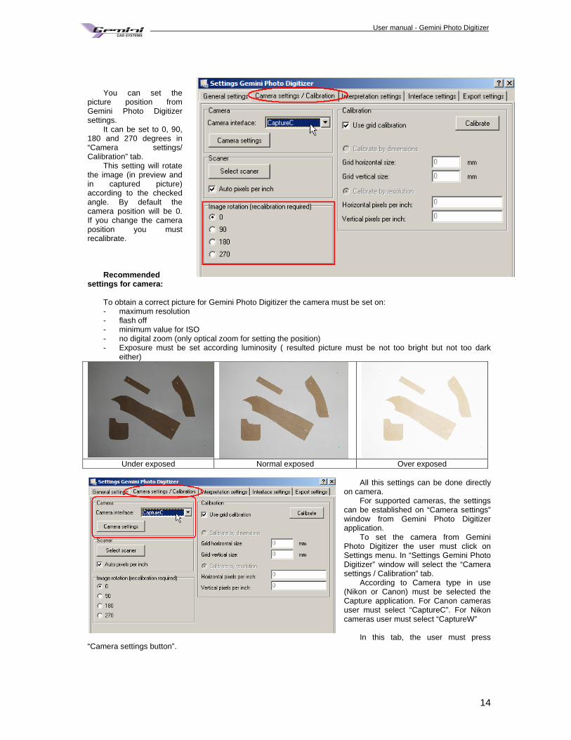
You can set the
picture position from Gemini Photo Digitizer settings.
It can be set to 0, 90, 180 and 270 degrees in “Camera settings/ Calibration” tab.
This setting will rotate the image (in preview and in captured picture) according to the checked angle. By default the camera position will be 0. If you change the camera position you must recalibrate.
Recommended
settings for camera: To obtain a correct picture for Gemini Photo Digitizer the camera must be set on: - maximum resolution - flash off - minimum value for ISO - no digital zoom (only optical zoom for setting the position) - Exposure must be set according luminosity ( resulted picture must be not too bright but not too dark
either)
Under exposed Normal exposed Over exposed
All this settings can be done directly
on camera. For supported cameras, the settings
can be established on “Camera settings” window from Gemini Photo Digitizer application.
To set the camera from Gemini Photo Digitizer the user must click on Settings menu. In “Settings Gemini Photo Digitizer” window will select the “Camera settings / Calibration” tab.
According to Camera type in use (Nikon or Canon) must be selected the Capture application. For Canon cameras user must select “CaptureC”. For Nikon cameras user must select “CaptureW”
In this tab, the user must press
“Camera settings button”.
User manual - Gemini Photo Digitizer Plan
15
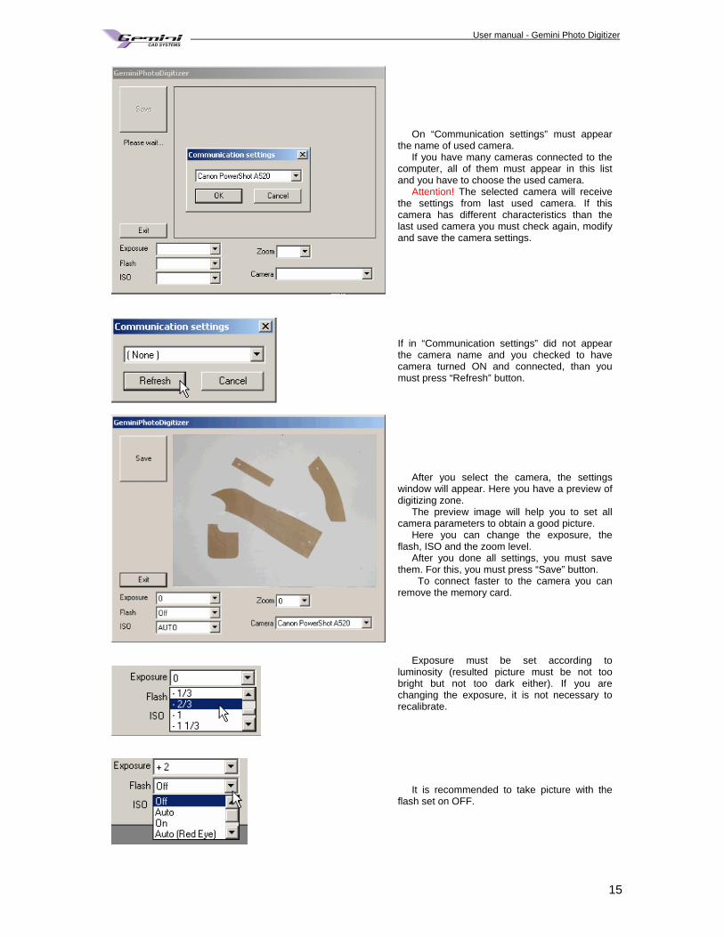
On “Communication settings” must appear the name of used camera.
If you have many cameras connected to the computer, all of them must appear in this list and you have to choose the used camera.
Attention! The selected camera will receive the settings from last used camera. If this camera has different characteristics than the last used camera you must check again, modify and save the camera settings.
If in “Communication settings” did not appear the camera name and you checked to have camera turned ON and connected, than you must press “Refresh” button.
After you select the camera, the settings window will appear. Here you have a preview of digitizing zone.
The preview image will help you to set all camera parameters to obtain a good picture.
Here you can change the exposure, the flash, ISO and the zoom level.
After you done all settings, you must save them. For this, you must press “Save” button.
To connect faster to the camera you can remove the memory card.
Exposure must be set according to luminosity (resulted picture must be not too bright but not too dark either). If you are changing the exposure, it is not necessary to recalibrate.
It is recommended to take picture with the flash set on OFF.
User manual - Gemini Photo Digitizer Plan
16
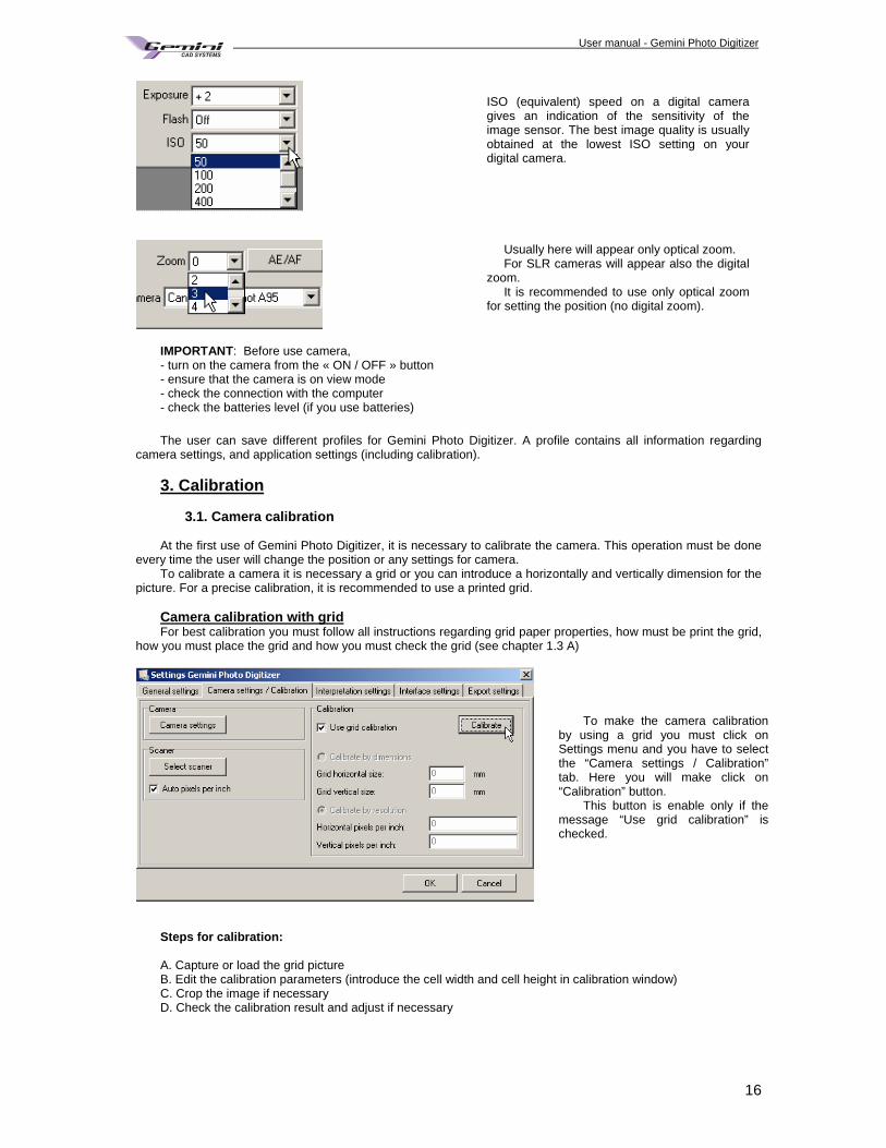
ISO (equivalent) speed on a digital camera gives an indication of the sensitivity of the image sensor. The best image quality is usually obtained at the lowest ISO setting on your digital camera.
Usually here will appear only optical zoom. For SLR cameras will appear also the digital
zoom. It is recommended to use only optical zoom
for setting the position (no digital zoom).
IMPORTANT: Before use camera, - turn on the camera from the « ON / OFF » button - ensure that the camera is on view mode - check the connection with the computer - check the batteries level (if you use batteries)
The user can save different profiles for Gemini Photo Digitizer. A profile contains all information regarding
camera settings, and application settings (including calibration).
3. Calibration 3.1. Camera calibration
At the first use of Gemini Photo Digitizer, it is necessary to calibrate the camera. This operation must be done every time the user will change the position or any settings for camera.
To calibrate a camera it is necessary a grid or you can introduce a horizontally and vertically dimension for the picture. For a precise calibration, it is recommended to use a printed grid.
Camera calibration with grid For best calibration you must follow all instructions regarding grid paper properties, how must be print the grid,
how you must place the grid and how you must check the grid (see chapter 1.3 A)
To make the camera calibration by using a grid you must click on Settings menu and you have to select the “Camera settings / Calibration” tab. Here you will make click on “Calibration” button.
This button is enable only if the message “Use grid calibration” is checked.
Steps for calibration: A. Capture or load the grid picture B. Edit the calibration parameters (introduce the cell width and cell height in calibration window) C. Crop the image if necessary D. Check the calibration result and adjust if necessary
User manual - Gemini Photo Digitizer Plan
17
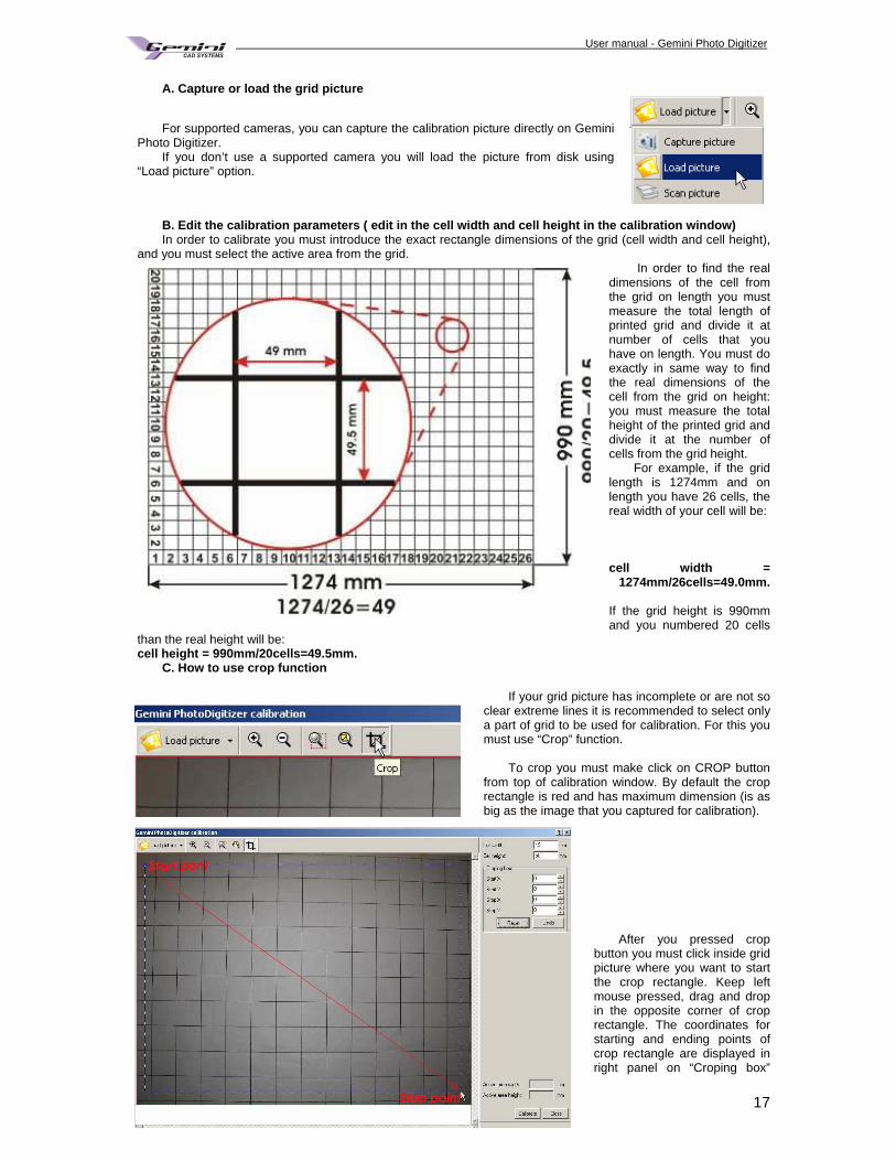
A. Capture or load the grid picture
For supported cameras, you can capture the calibration picture directly on Gemini Photo Digitizer.
If you don’t use a supported camera you will load the picture from disk using “Load picture” option.
B. Edit the calibration parameters ( edit in the ce ll width and cell height in the calibration window) In order to calibrate you must introduce the exact rectangle dimensions of the grid (cell width and cell height),
and you must select the active area from the grid. In order to find the real
dimensions of the cell from the grid on length you must measure the total length of printed grid and divide it at number of cells that you have on length. You must do exactly in same way to find the real dimensions of the cell from the grid on height: you must measure the total height of the printed grid and divide it at the number of cells from the grid height.
For example, if the grid length is 1274mm and on length you have 26 cells, the real width of your cell will be: cell width =
1274mm/26cells=49.0mm. If the grid height is 990mm and you numbered 20 cells
than the real height will be: cell height = 990mm/20cells=49.5mm.
C. How to use crop function
If your grid picture has incomplete or are not so clear extreme lines it is recommended to select only a part of grid to be used for calibration. For this you must use “Crop” function.
To crop you must make click on CROP button
from top of calibration window. By default the crop rectangle is red and has maximum dimension (is as big as the image that you captured for calibration).
After you pressed crop
button you must click inside grid picture where you want to start the crop rectangle. Keep left mouse pressed, drag and drop in the opposite corner of crop rectangle. The coordinates for starting and ending points of crop rectangle are displayed in right panel on “Croping box”
User manual - Gemini Photo Digitizer Plan
18
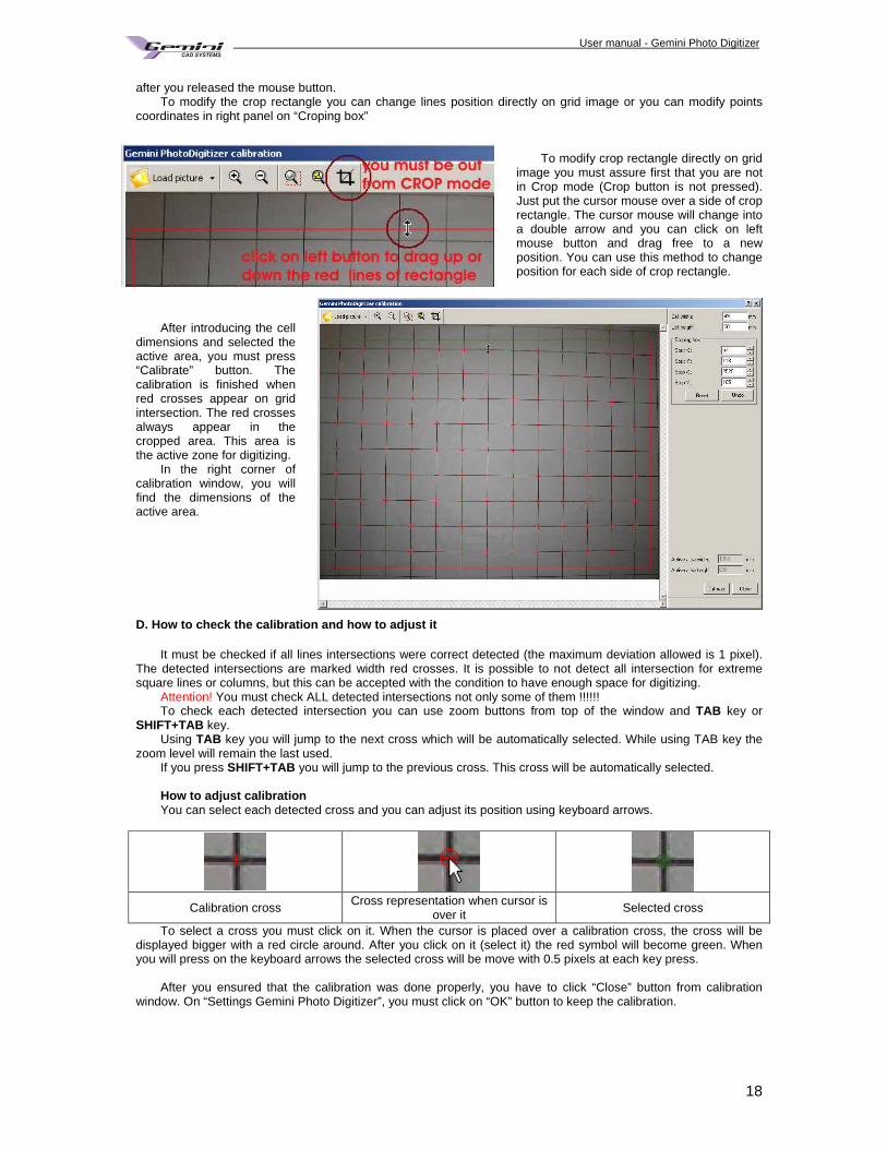
after you released the mouse button. To modify the crop rectangle you can change lines position directly on grid image or you can modify points
coordinates in right panel on “Croping box”
To modify crop rectangle directly on grid
image you must assure first that you are not in Crop mode (Crop button is not pressed). Just put the cursor mouse over a side of crop rectangle. The cursor mouse will change into a double arrow and you can click on left mouse button and drag free to a new position. You can use this method to change position for each side of crop rectangle.
After introducing the cell
dimensions and selected the active area, you must press “Calibrate” button. The calibration is finished when red crosses appear on grid intersection. The red crosses always appear in the cropped area. This area is the active zone for digitizing.
In the right corner of calibration window, you will find the dimensions of the active area.
D. How to check the calibration and how to adjust i t
It must be checked if all lines intersections were correct detected (the maximum deviation allowed is 1 pixel). The detected intersections are marked width red crosses. It is possible to not detect all intersection for extreme square lines or columns, but this can be accepted with the condition to have enough space for digitizing.
Attention! You must check ALL detected intersections not only some of them !!!!!! To check each detected intersection you can use zoom buttons from top of the window and TAB key or
SHIFT+TAB key. Using TAB key you will jump to the next cross which will be automatically selected. While using TAB key the
zoom level will remain the last used. If you press SHIFT+TAB you will jump to the previous cross. This cross will be automatically selected. How to adjust calibration You can select each detected cross and you can adjust its position using keyboard arrows.
Calibration cross Cross representation when cursor is over it
Selected cross
To select a cross you must click on it. When the cursor is placed over a calibration cross, the cross will be displayed bigger with a red circle around. After you click on it (select it) the red symbol will become green. When you will press on the keyboard arrows the selected cross will be move with 0.5 pixels at each key press.
After you ensured that the calibration was done properly, you have to click “Close” button from calibration
window. On “Settings Gemini Photo Digitizer”, you must click on “OK” button to keep the calibration.
User manual - Gemini Photo Digitizer Plan
19
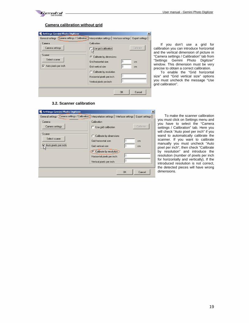
Camera calibration without grid
If you don’t use a grid for calibration you can introduce horizontal and the vertical dimension of picture in “Camera settings / Calibration” tab from “Settings Gemini Photo Digitizer” window. This dimension must be very precise to obtain a correct calibration.
To enable the “Grid horizontal size” and “Grid vertical size” options you must uncheck the message “Use grid calibration”.
3.2. Scanner calibration
To make the scanner calibration you must click on Settings menu and you have to select the “Camera settings / Calibration” tab. Here you will check “Auto pixel per inch” if you wand to automatically calibrate the scanner. If you want to calibrate manually you must uncheck “Auto pixel per inch”, then check “Calibrate by resolution” and introduce the resolution (number of pixels per inch for horizontally and vertically). If the introduced resolution is not correct, the detected pieces will have wrong dimensions.
User manual - Gemini Photo Digitizer Plan
20
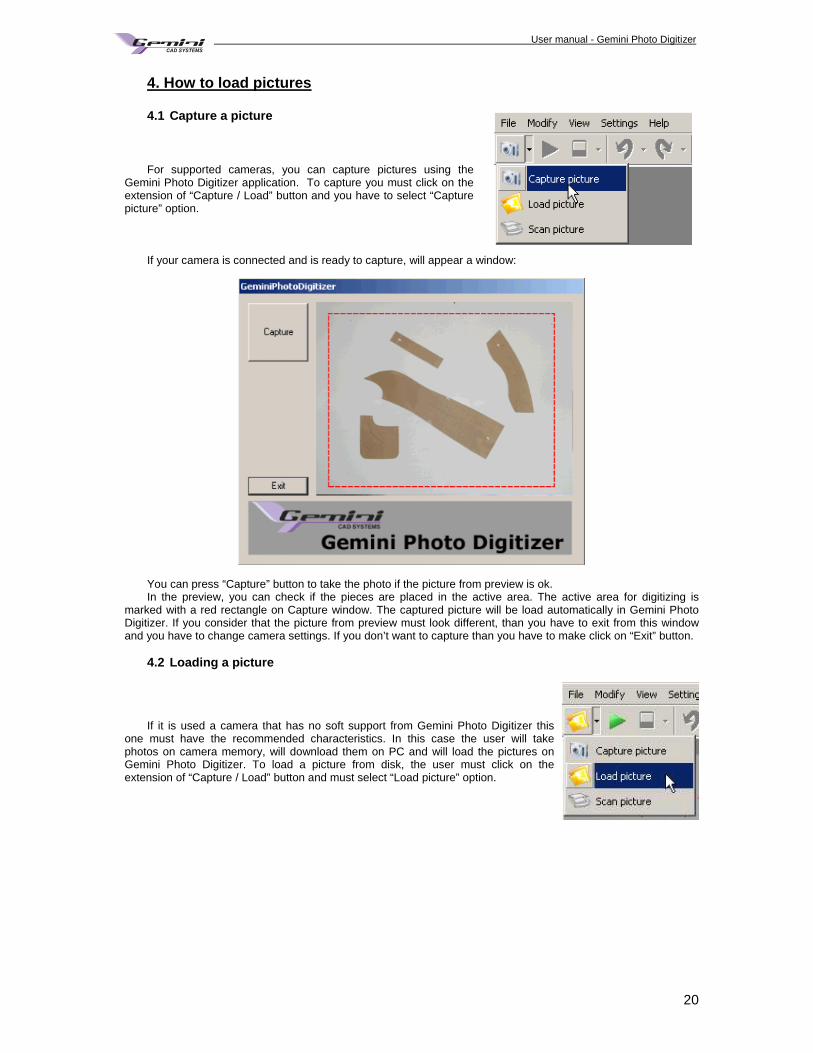
4. How to load pictures 4.1 Capture a picture For supported cameras, you can capture pictures using the
Gemini Photo Digitizer application. To capture you must click on the extension of “Capture / Load” button and you have to select “Capture picture” option.
If your camera is connected and is ready to capture, will appear a window: You can press “Capture” button to take the photo if the picture from preview is ok. In the preview, you can check if the pieces are placed in the active area. The active area for digitizing is
marked with a red rectangle on Capture window. The captured picture will be load automatically in Gemini Photo Digitizer. If you consider that the picture from preview must look different, than you have to exit from this window and you have to change camera settings. If you don’t want to capture than you have to make click on “Exit” button.
4.2 Loading a picture
If it is used a camera that has no soft support from Gemini Photo Digitizer this one must have the recommended characteristics. In this case the user will take photos on camera memory, will download them on PC and will load the pictures on Gemini Photo Digitizer. To load a picture from disk, the user must click on the extension of “Capture / Load” button and must select “Load picture” option.
User manual - Gemini Photo Digitizer Plan
21
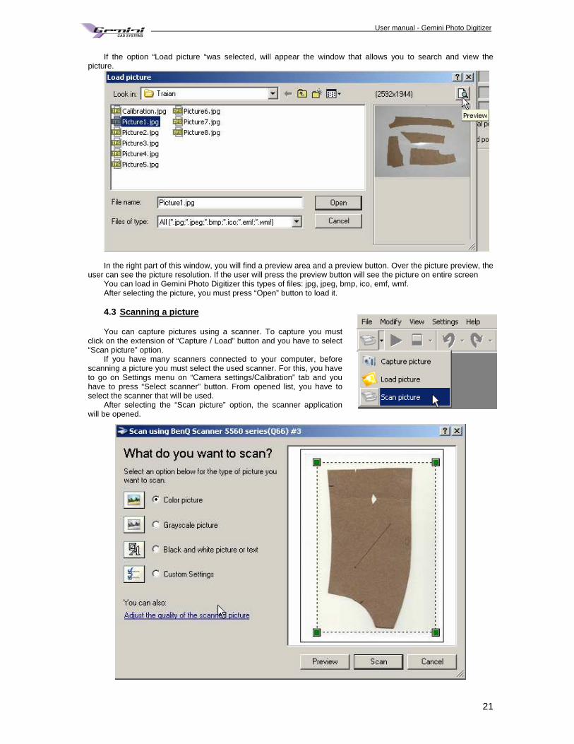
If the option “Load picture “was selected, will appear the window that allows you to search and view the picture.
In the right part of this window, you will find a preview area and a preview button. Over the picture preview, the
user can see the picture resolution. If the user will press the preview button will see the picture on entire screen You can load in Gemini Photo Digitizer this types of files: jpg, jpeg, bmp, ico, emf, wmf. After selecting the picture, you must press “Open” button to load it.
4.3 Scanning a picture You can capture pictures using a scanner. To capture you must
click on the extension of “Capture / Load” button and you have to select “Scan picture” option.
If you have many scanners connected to your computer, before scanning a picture you must select the used scanner. For this, you have to go on Settings menu on “Camera settings/Calibration” tab and you have to press “Select scanner” button. From opened list, you have to select the scanner that will be used.
After selecting the “Scan picture” option, the scanner application will be opened.
User manual - Gemini Photo Digitizer Plan
22
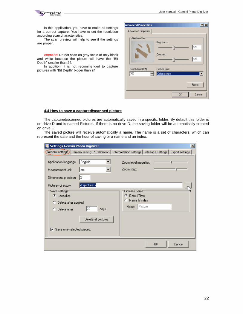
In this application, you have to make all settings
for a correct capture. You have to set the resolution according scan characteristics.
The scan preview will help to see if the settings are proper.
Attention! Do not scan on gray scale or only black
and white because the picture will have the “Bit Depth” smaller than 24.
In addition, it is not recommended to capture pictures with “Bit Depth” bigger than 24.
4.4 How to save a captured/scanned picture The captured/scanned pictures are automatically saved in a specific folder. By default this folder is
on drive D and is named Pictures. If there is no drive D, the saving folder will be automatically created on drive C.
The saved picture will receive automatically a name. The name is a set of characters, which can represent the date and the hour of saving or a name and an index.
User manual - Gemini Photo Digitizer Plan
23
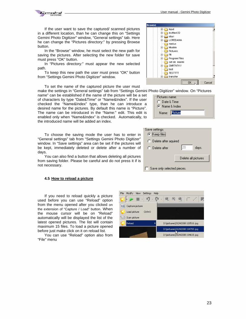
If the user want to save the captured/ scanned pictures
in a different location, than he can change this on “Settings Gemini Photo Digitizer” window, “General settings” tab. Here he can change the “Pictures directory:” by pressing Browse button.
In the “Browse” window, he must select the new path for saving the pictures. After selecting the new folder for save must press “OK” button.
In “Pictures directory:” must appear the new selected path.
To keep this new path the user must press “OK” button from “Settings Gemini Photo Digitizer” window.
To set the name of the captured picture the user must
make the settings in “General settings” tab from “Settings Gemini Photo Digitizer” window. On “Pictures name” can be established if the name of the picture will be a set of characters by type “Date&Time” or “Name&Index”. If the user checked the “Name&Index” type, than he can introduce a desired name for the pictures. By default this name is “Picture”. The name can be introduced in the “Name:” edit. This edit is enabled only when “Name&Index” is checked. Automatically, to the introduced name will be added an index.
To choose the saving mode the user has to enter in “General settings” tab from “Settings Gemini Photo Digitizer” window. In “Save settings” area can be set if the pictures will be kept, immediately deleted or delete after a number of days.
You can also find a button that allows deleting all pictures from saving folder. Please be careful and do not press it if is not necessary.
4.5 How to reload a picture If you need to reload quickly a picture
used before you can use “Reload” option from the menu opened after you clicked on the extension of “Capture / Load” button. When the mouse cursor will be on “Reload” automatically will be displayed the list of the latest opened pictures. The list will contain maximum 15 files. To load a picture opened before just make click on it on reload list.
You can use “Reload” option also from “File” menu
User manual - Gemini Photo Digitizer Plan
24
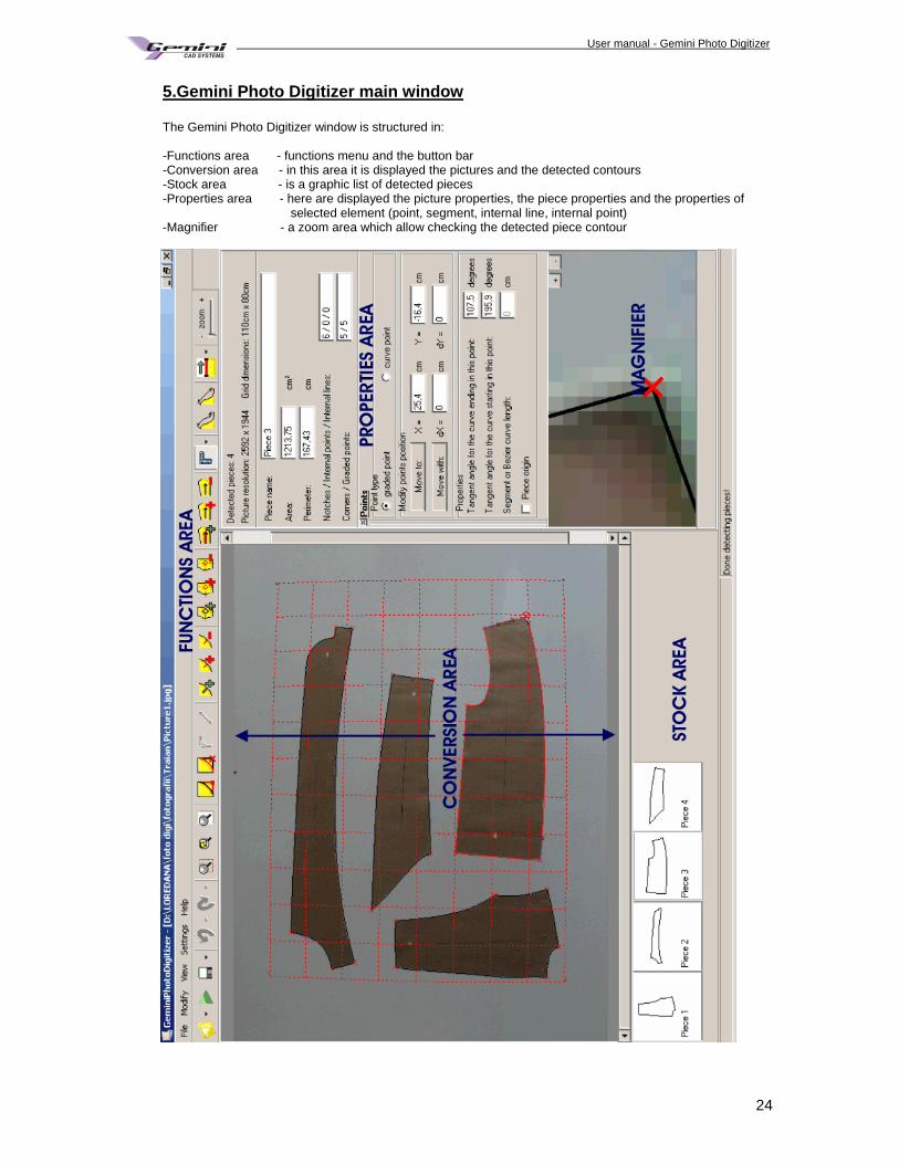
5.Gemini Photo Digitizer main window The Gemini Photo Digitizer window is structured in: -Functions area - functions menu and the button bar -Conversion area - in this area it is displayed the pictures and the detected contours -Stock area - is a graphic list of detected pieces -Properties area - here are displayed the picture properties, the piece properties and the properties of selected element (point, segment, internal line, internal point) -Magnifier - a zoom area which allow checking the detected piece contour
User manual - Gemini Photo Digitizer Plan
25
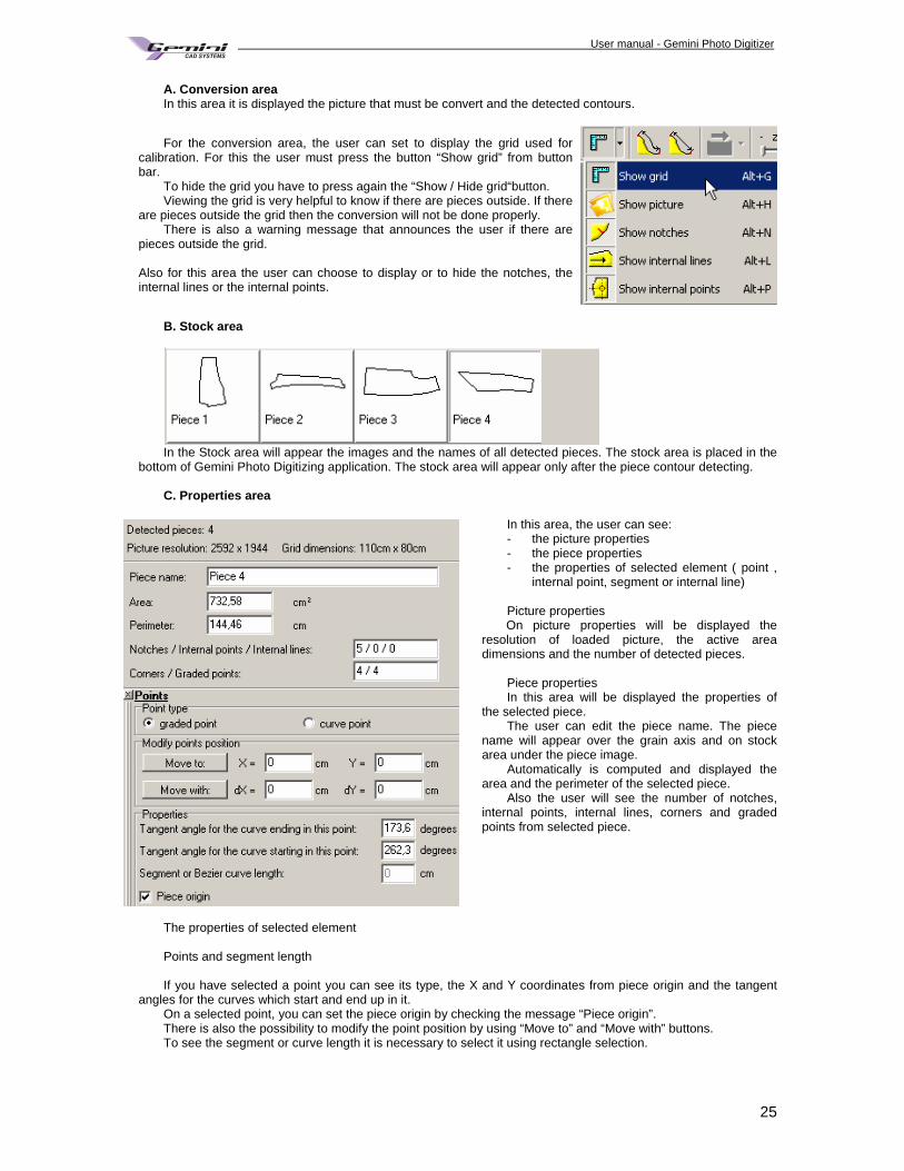
A. Conversion area In this area it is displayed the picture that must be convert and the detected contours.
For the conversion area, the user can set to display the grid used for calibration. For this the user must press the button “Show grid” from button bar.
To hide the grid you have to press again the “Show / Hide grid“button. Viewing the grid is very helpful to know if there are pieces outside. If there
are pieces outside the grid then the conversion will not be done properly. There is also a warning message that announces the user if there are
pieces outside the grid.
Also for this area the user can choose to display or to hide the notches, the internal lines or the internal points.
B. Stock area
In the Stock area will appear the images and the names of all detected pieces. The stock area is placed in the
bottom of Gemini Photo Digitizing application. The stock area will appear only after the piece contour detecting. C. Properties area
In this area, the user can see: - the picture properties - the piece properties - the properties of selected element ( point ,
internal point, segment or internal line) Picture properties
On picture properties will be displayed the resolution of loaded picture, the active area dimensions and the number of detected pieces.
Piece properties In this area will be displayed the properties of
the selected piece. The user can edit the piece name. The piece
name will appear over the grain axis and on stock area under the piece image.
Automatically is computed and displayed the area and the perimeter of the selected piece.
Also the user will see the number of notches, internal points, internal lines, corners and graded points from selected piece.
The properties of selected element Points and segment length If you have selected a point you can see its type, the X and Y coordinates from piece origin and the tangent
angles for the curves which start and end up in it. On a selected point, you can set the piece origin by checking the message “Piece origin”. There is also the possibility to modify the point position by using “Move to” and “Move with” buttons. To see the segment or curve length it is necessary to select it using rectangle selection.
User manual - Gemini Photo Digitizer Plan
26
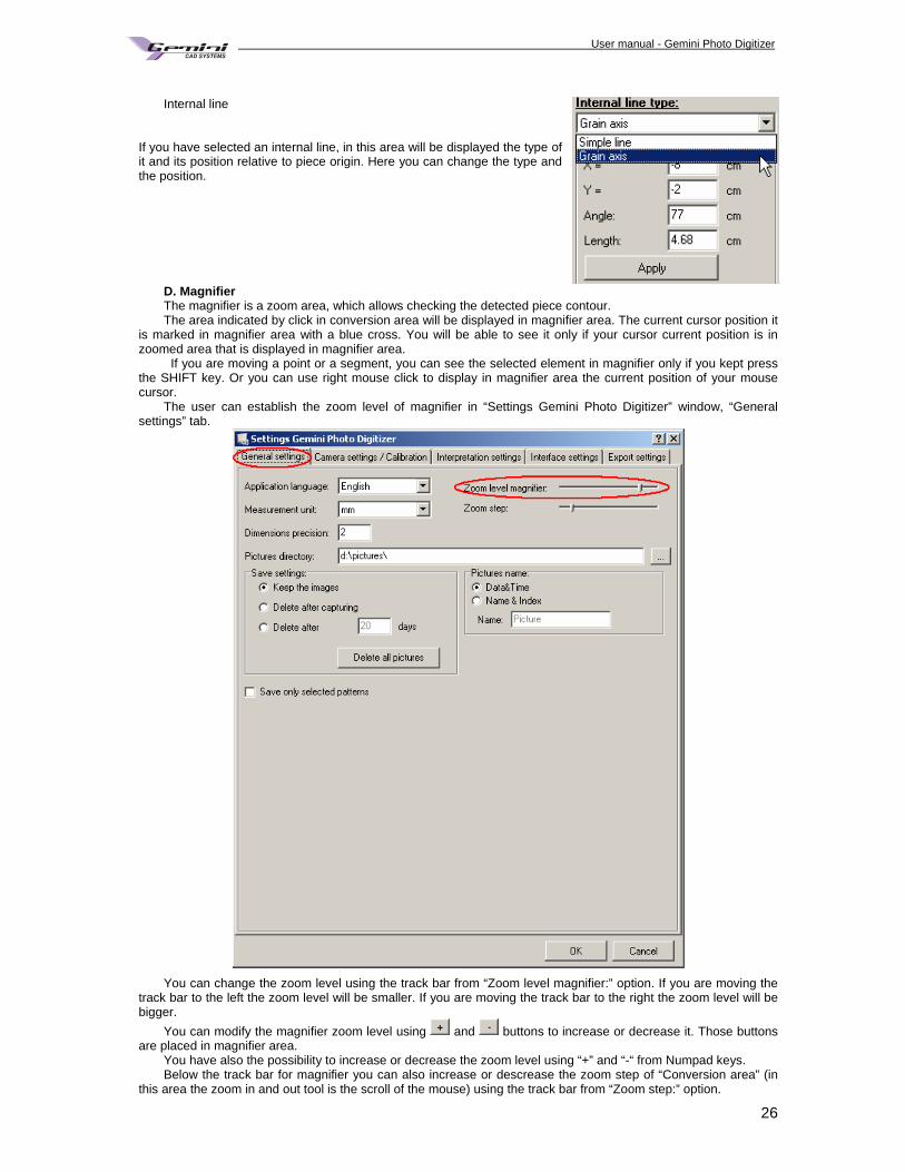
Internal line
If you have selected an internal line, in this area will be displayed the type of it and its position relative to piece origin. Here you can change the type and the position.
D. Magnifier The magnifier is a zoom area, which allows checking the detected piece contour. The area indicated by click in conversion area will be displayed in magnifier area. The current cursor position it
is marked in magnifier area with a blue cross. You will be able to see it only if your cursor current position is in zoomed area that is displayed in magnifier area.
If you are moving a point or a segment, you can see the selected element in magnifier only if you kept press the SHIFT key. Or you can use right mouse click to display in magnifier area the current position of your mouse cursor.
The user can establish the zoom level of magnifier in “Settings Gemini Photo Digitizer” window, “General settings” tab.
You can change the zoom level using the track bar from “Zoom level magnifier:” option. If you are moving the
track bar to the left the zoom level will be smaller. If you are moving the track bar to the right the zoom level will be bigger.
You can modify the magnifier zoom level using and buttons to increase or decrease it. Those buttons are placed in magnifier area.
You have also the possibility to increase or decrease the zoom level using “+” and “-“ from Numpad keys. Below the track bar for magnifier you can also increase or descrease the zoom step of “Conversion area” (in
this area the zoom in and out tool is the scroll of the mouse) using the track bar from “Zoom step:” option.
User manual - Gemini Photo Digitizer Plan
27
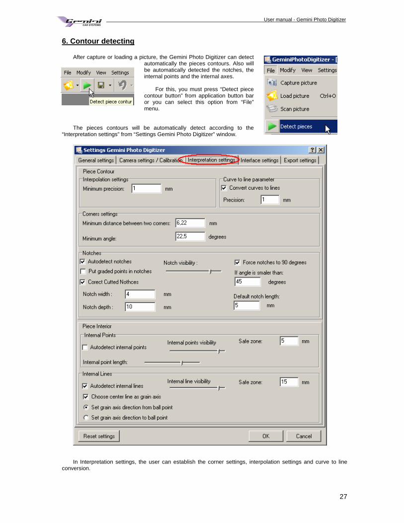
6. Contour detecting
After capture or loading a picture, the Gemini Photo Digitizer can detect automatically the pieces contours. Also will be automatically detected the notches, the internal points and the internal axes.
For this, you must press “Detect piece
contour button” from application button bar or you can select this option from “File” menu.
The pieces contours will be automatically detect according to the
“Interpretation settings” from “Settings Gemini Photo Digitizer” window.
In Interpretation settings, the user can establish the corner settings, interpolation settings and curve to line
conversion.
User manual - Gemini Photo Digitizer Plan
28
Interpolation settings
Maximum deviation
Interpolation is a function that insures the conversion of straight segments from automat detection into Bezier curves with an accurate following of the initial contour. Here you can set the maximal deviation of the resulted contour after interpolation related to the piece contour. For a smaller deviation there is an accuracy increase. By default, it is set at 0,1cm.
Curve to line parameter
Convert curves to lines If this option is checked, the curves with control points situated at a distance smaller than approximation value will be converted to lines.
Approximation Recommended value is 2 or 3 mm. Corner settings
Minimum distance between two corners
The distance between two corners must be bigger than the introduced value. If you must detect pieces having many corners very close one to another you must change the value from “Minimum distance between two corners” By default, it is set at 1 cm.
Minimum angle
The user can set the minimum value for a corner angle. If on conversion for a point will be found an angle smaller than the introduced value, than that point will not be a corner point. The recommended values for the minimum angle are between 20 and 30 degrees. By default, it is set at 22.5degrees.
Set corners as graded points
The user can set the type of point that will correspond to a corner. The points from piece contour can be cusp or can be smooth. All the time a corner point will be a cusp point. Even if you uncheck this message and corners will be marked as curve points, the corners will not be interpolated and will remain cusp. By default, this option is checked and the corners will be detected as cusp graded points.
Notches
Autodetect notches If this function is checked, the notches will be detected automatically in the same time with the piece contour.
Force notches to 90 degrees If angle is smaller than:
The setting “Force notches to 90 degrees” will be applied only if the angle between the detected notch and the segment on which it is placed is smaller then the value which you enter on” If angle is smaller than:”.
Default notch length
If you enter a value in the field of this option all the notches will have the dimension entered in this field. The new created notches will have the length set here as default.
Put graded points in notches If this option is checked, automatically, for each detected notch will be added a grading point on pattern contour.
Corect Cutted Notches Notch width: Notch depth
For patterns with cutted notches, not drawn notches, you can use this option to detect the cuttings from contour as notches. For this you must set the width and the depth values. Each cutting from piece contour which has the width and depth values as you set will be detected as notches.
Notch visibility
If you will change the track bar position you will set the visibility level for detected notches. The position that you set here will be initial position of notch visibility track bar from main window of Gemini Photo Digitizer. The maximum left position will allow detecting as notches only the best marks for notches from patterns. The maximum right position will allow detecting as notches all the marks from patterns which appears as notches.
User manual - Gemini Photo Digitizer Plan
29
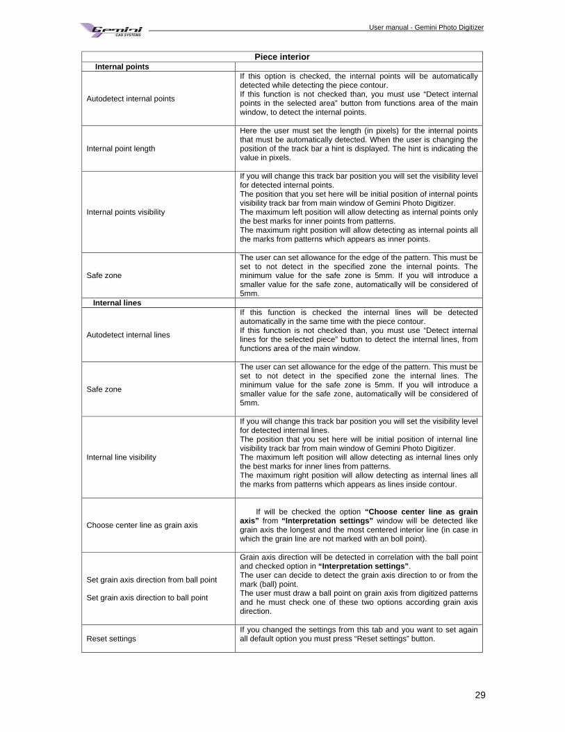
Piece interior Internal points
Autodetect internal points
If this option is checked, the internal points will be automatically detected while detecting the piece contour. If this function is not checked than, you must use “Detect internal points in the selected area” button from functions area of the main window, to detect the internal points.
Internal point length
Here the user must set the length (in pixels) for the internal points that must be automatically detected. When the user is changing the position of the track bar a hint is displayed. The hint is indicating the value in pixels.
Internal points visibility
If you will change this track bar position you will set the visibility level for detected internal points. The position that you set here will be initial position of internal points visibility track bar from main window of Gemini Photo Digitizer. The maximum left position will allow detecting as internal points only the best marks for inner points from patterns. The maximum right position will allow detecting as internal points all the marks from patterns which appears as inner points.
Safe zone
The user can set allowance for the edge of the pattern. This must be set to not detect in the specified zone the internal points. The minimum value for the safe zone is 5mm. If you will introduce a smaller value for the safe zone, automatically will be considered of 5mm.
Internal lines
Autodetect internal lines
If this function is checked the internal lines will be detected automatically in the same time with the piece contour. If this function is not checked than, you must use “Detect internal lines for the selected piece” button to detect the internal lines, from functions area of the main window.
Safe zone
The user can set allowance for the edge of the pattern. This must be set to not detect in the specified zone the internal lines. The minimum value for the safe zone is 5mm. If you will introduce a smaller value for the safe zone, automatically will be considered of 5mm.
Internal line visibility
If you will change this track bar position you will set the visibility level for detected internal lines. The position that you set here will be initial position of internal line visibility track bar from main window of Gemini Photo Digitizer. The maximum left position will allow detecting as internal lines only the best marks for inner lines from patterns. The maximum right position will allow detecting as internal lines all the marks from patterns which appears as lines inside contour.
Choose center line as grain axis
If will be checked the option “Choose center line as grain
axis” from “Interpretation settings” window will be detected like grain axis the longest and the most centered interior line (in case in which the grain line are not marked with an boll point).
Set grain axis direction from ball point Set grain axis direction to ball point
Grain axis direction will be detected in correlation with the ball point and checked option in “Interpretation settings” . The user can decide to detect the grain axis direction to or from the mark (ball) point. The user must draw a ball point on grain axis from digitized patterns and he must check one of these two options according grain axis direction.
Reset settings If you changed the settings from this tab and you want to set again all default option you must press “Reset settings” button.
User manual - Gemini Photo Digitizer Plan
30
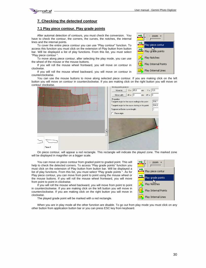
7. Checking the detected contour 7.1 Play piece contour. Play grade points After automat detection of contours, you must check the conversion. You
have to check the contour, the corners, the curves, the notches, the internal lines and the internal points.
To cover the entire piece contour you can use “Play contour” function. To access this function you must click on the extension of Play button from button bar. Will be displayed a list of play functions. From this list, you must select “Play piece contour “.
To move along piece contour, after selecting the play mode, you can use the wheel of the mouse or the mouse buttons.
If you will roll the mouse wheel frontward, you will move on contour in clockwise.
If you will roll the mouse wheel backward, you will move on contour in counterclockwise.
You can use the mouse buttons to move along selected piece contour. If you are making click on the left button you will move on contour in counterclockwise. If you are making click on the right button you will move on contour clockwise.
On piece contour, will appear a red rectangle. This rectangle will indicate the played zone. The marked zone
will be displayed in magnifier on a bigger scale. You can move on piece contour from graded point to graded point. This will
help to check the detected corners. To access “Play grade points” function you must click on the extension of Play button from button bar. Will be displayed a list of play functions. From this list, you must select “Play grade points “. As for Play piece contour, you can move from point to point using the mouse wheel or the mouse buttons. If you will roll the mouse wheel frontward, you will move from point to point in clockwise.
If you will roll the mouse wheel backward, you will move from point to point in counterclockwise. If you are making click on the left button you will move in counterclockwise. If you are making click on the right button you will move in clockwise.
The played grade point will be marked with a red rectangle. When you are in play mode all the other function are disable. To go out from play mode you must click on any
other button from application button bar or you can press ESC key from keyboard.
User manual - Gemini Photo Digitizer Plan
31
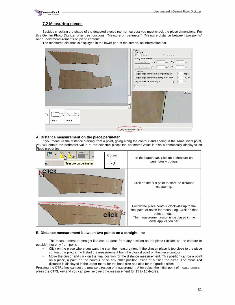
7.2 Measuring pieces Besides checking the shape of the detected pieces (corner, curves) you must check the piece dimensions. For
this Gemini Photo Digitizer offer tree functions: “Measure on perimeter”, “Measure distance between two points” and “Show measurements on piece contour”.
The measured distance is displayed in the lower part of the screen, on information bar.
A. Distance measurement on the piece perimeter If you measure the distance starting from a point, going along the contour and ending in the same initial point,
you will obtain the perimeter value of the selected piece; the perimeter value is also automatically displayed on Piece properties.
In the button bar, click on « Measure on perimeter » button.
Click on the first point to start the distance measuring.
Follow the piece contour clockwise up to the final point or notch for measuring. Click on that
point or notch. The measurement result is displayed in the
lower application bar.
B. Distance measurement between two points on a strai ght line
The measurement on straight line can be done from any position on the piece ( inside, on the contour or outside), not only from point.
• Click on the place where you want the start the measurement. If the chosen place is too close to the piece contour, the program will start the measurement from the closest point on the piece contour.
• Move the cursor and click on the final position for the distance measurement. This position can be a point on a piece, a point on the contour or on any other position inside or outside the piece. The measured distance is displayed in the upper menu for the base size and also for the graded sizes.
Pressing the CTRL key can set the precise direction of measurement. After select the initial point of measurement, press the CTRL key and you can precise direct the measurement for 15 to 15 degree.
Cursor
User manual - Gemini Photo Digitizer Plan
32
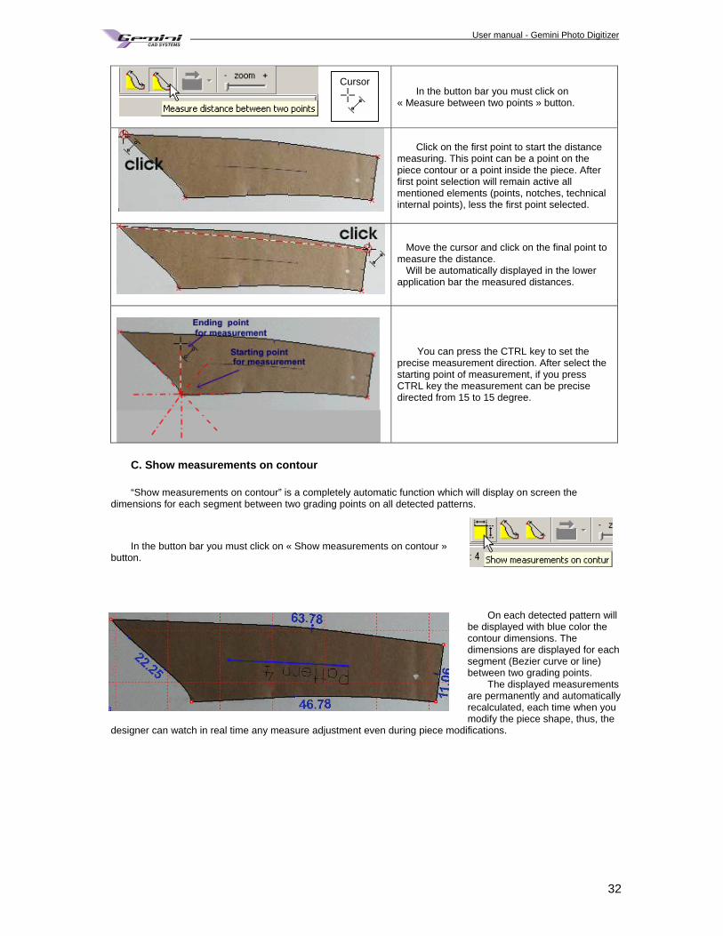
In the button bar you must click on « Measure between two points » button.
Click on the first point to start the distance measuring. This point can be a point on the piece contour or a point inside the piece. After first point selection will remain active all mentioned elements (points, notches, technical internal points), less the first point selected.
Move the cursor and click on the final point to measure the distance.
Will be automatically displayed in the lower application bar the measured distances.
You can press the CTRL key to set the precise measurement direction. After select the starting point of measurement, if you press CTRL key the measurement can be precise directed from 15 to 15 degree.
C. Show measurements on contour “Show measurements on contour” is a completely automatic function which will display on screen the
dimensions for each segment between two grading points on all detected patterns.
In the button bar you must click on « Show measurements on contour »
button.
On each detected pattern will
be displayed with blue color the contour dimensions. The dimensions are displayed for each segment (Bezier curve or line) between two grading points.
The displayed measurements are permanently and automatically recalculated, each time when you modify the piece shape, thus, the
designer can watch in real time any measure adjustment even during piece modifications.
Cursor
User manual - Gemini Photo Digitizer Plan
33
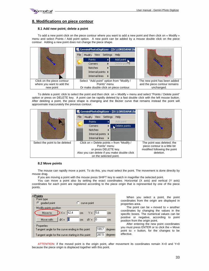
8. Modifications on piece contour 8.1 Add new point; delete a point
To add a new point click on the piece contour where you want to add a new point and then click on « Modify »
menu and select Points / Add point option. A new point can be added by a mouse double click on the piece contour. Adding a new point does not change the piece shape.
Click on the piece contour where you want to add the
new point
Select “Add point” option from “Modify / Points” menu
Or make double click on piece contour.
The new point has been added and the piece contour remains
unchanged.
To delete a point: click to select the point and then click on « Modify » menu and select “Points / Delete point” option or press on DELETE key. A point can be rapidly deleted by a fast double click with the left mouse button. After deleting a point, the piece shape is changing and the Bezier curve that remains instead the point will approximate inaccurately the previous contour.
Select the point to be deleted Click on « Delete points » from “Modify /
Points” menu or press DELETE key.
Also you can delete if you make double click on the selected point.
The point was deleted; the piece contour is a little bit
modified following the point deletion.
8.2 Move points The mouse can rapidly move a point. To do this, you must select the point. The movement is done directly by
mouse drag. If you are moving a point with the mouse press SHIFT key to watch in magnifier the selected point. You can move a point also by setting the exact coordinates. Horizontal (X axis) and vertical (Y axis)
coordinates for each point are registered according to the piece origin that is represented by one of the piece points.
When you select a point, the point
coordinates from the origin are displayed in properties area.
The point can be « moved to » another coordinates by changing the values in the specific boxes. The numerical values can be positive or negative, according to point position from the origin point.
After entering the new point coordinates you must press ENTER or to click the « Move point to: » button, for the changes to be effective.
ATTENTION: if the moved point is the origin point, after movement its coordinates remain X=0 and Y=0
because the piece origin is displaced together with this point.
User manual - Gemini Photo Digitizer Plan
34
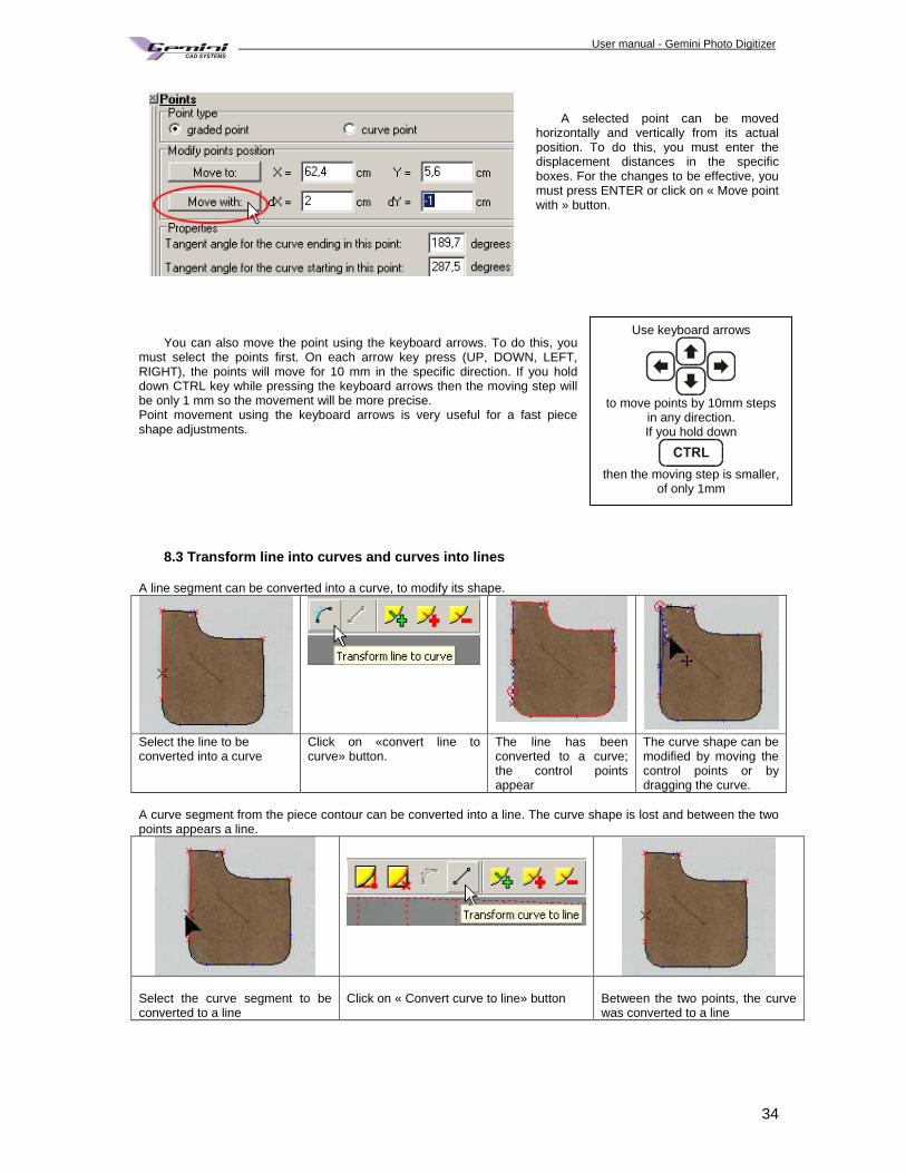
A selected point can be moved
horizontally and vertically from its actual position. To do this, you must enter the displacement distances in the specific boxes. For the changes to be effective, you must press ENTER or click on « Move point with » button.
You can also move the point using the keyboard arrows. To do this, you must select the points first. On each arrow key press (UP, DOWN, LEFT, RIGHT), the points will move for 10 mm in the specific direction. If you hold down CTRL key while pressing the keyboard arrows then the moving step will be only 1 mm so the movement will be more precise. Point movement using the keyboard arrows is very useful for a fast piece shape adjustments.
8.3 Transform line into curves and curves into lines
A line segment can be converted into a curve, to modify its shape.
Select the line to be converted into a curve
Click on «convert line to curve» button.
The line has been converted to a curve; the control points appear
The curve shape can be modified by moving the control points or by dragging the curve.
A curve segment from the piece contour can be converted into a line. The curve shape is lost and between the two points appears a line.
Select the curve segment to be converted to a line
Click on « Convert curve to line» button
Between the two points, the curve was converted to a line
Use keyboard arrows
to move points by 10mm steps
in any direction. If you hold down
then the moving step is smaller,
of only 1mm
User manual - Gemini Photo Digitizer Plan
35
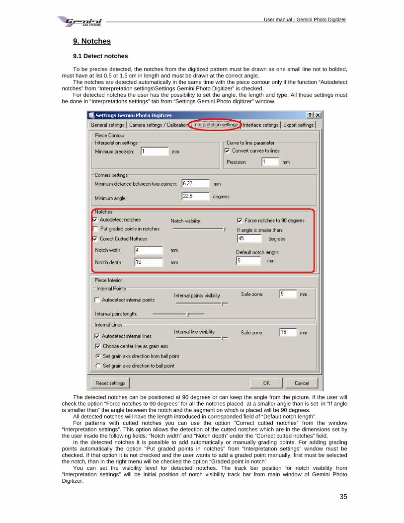
9. Notches 9.1 Detect notches To be precise detected, the notches from the digitized pattern must be drawn as one small line not to bolded,
must have at list 0.5 or 1.5 cm in length and must be drawn at the correct angle. The notches are detected automatically in the same time with the piece contour only if the function “Autodetect
notches” from “Interpretation settings\Settings Gemini Photo Digitizer” is checked. For detected notches the user has the possibility to set the angle, the length and type. All these settings must
be done in “Interpretations settings” tab from “Settings Gemini Photo digitizer” window.
The detected notches can be positioned at 90 degrees or can keep the angle from the picture. If the user will check the option “Force notches to 90 degrees” for all the notches placed at a smaller angle than is set in “If angle is smaller than” the angle between the notch and the segment on which is placed will be 90 degrees.
All detected notches will have the length introduced in corresponded field of “Default notch length”. For patterns with cutted notches you can use the option “Correct cutted notches” from the window
“Interpretation settings”. This option allows the detection of the cutted notches which are in the dimensions set by the user inside the following fields: “Notch width” and “Notch depth” under the “Correct cutted notches” field.
In the detected notches it is possible to add automatically or manually grading points. For adding grading points automatically the option “Put graded points in notches” from “Interpretation settings” window must be checked. If that option it is not checked and the user wants to add a graded point manually, first must be selected the notch, than in the right menu will be checked the option “Graded point in notch”
You can set the visibility level for detected notches. The track bar position for notch visibility from “Interpretation settings” will be initial position of notch visibility track bar from main window of Gemini Photo Digitizer.
User manual - Gemini Photo Digitizer Plan
36
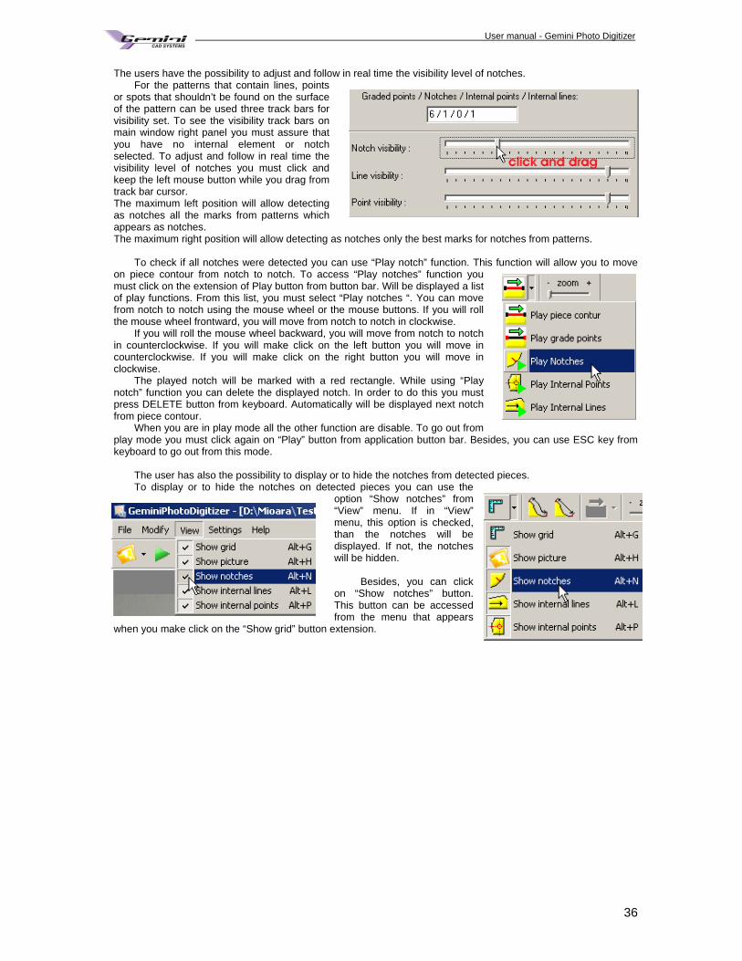
The users have the possibility to adjust and follow in real time the visibility level of notches. For the patterns that contain lines, points
or spots that shouldn’t be found on the surface of the pattern can be used three track bars for visibility set. To see the visibility track bars on main window right panel you must assure that you have no internal element or notch selected. To adjust and follow in real time the visibility level of notches you must click and keep the left mouse button while you drag from track bar cursor. The maximum left position will allow detecting as notches all the marks from patterns which appears as notches. The maximum right position will allow detecting as notches only the best marks for notches from patterns.
To check if all notches were detected you can use “Play notch” function. This function will allow you to move
on piece contour from notch to notch. To access “Play notches” function you must click on the extension of Play button from button bar. Will be displayed a list of play functions. From this list, you must select “Play notches “. You can move from notch to notch using the mouse wheel or the mouse buttons. If you will roll the mouse wheel frontward, you will move from notch to notch in clockwise.
If you will roll the mouse wheel backward, you will move from notch to notch in counterclockwise. If you will make click on the left button you will move in counterclockwise. If you will make click on the right button you will move in clockwise.
The played notch will be marked with a red rectangle. While using “Play notch” function you can delete the displayed notch. In order to do this you must press DELETE button from keyboard. Automatically will be displayed next notch from piece contour.
When you are in play mode all the other function are disable. To go out from play mode you must click again on “Play” button from application button bar. Besides, you can use ESC key from keyboard to go out from this mode.
The user has also the possibility to display or to hide the notches from detected pieces. To display or to hide the notches on detected pieces you can use the
option “Show notches” from “View” menu. If in “View” menu, this option is checked, than the notches will be displayed. If not, the notches will be hidden.
Besides, you can click
on “Show notches” button. This button can be accessed from the menu that appears
when you make click on the “Show grid” button extension.
User manual - Gemini Photo Digitizer Plan
37
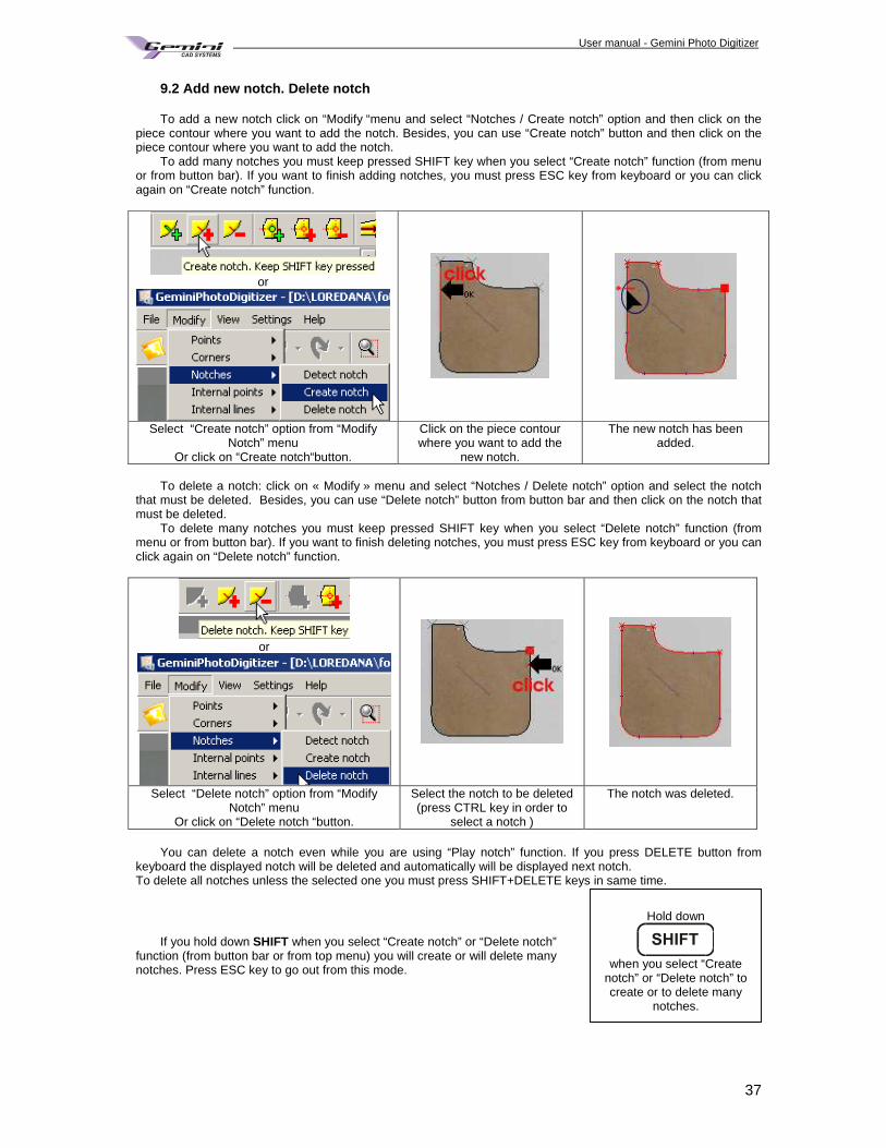
9.2 Add new notch. Delete notch To add a new notch click on “Modify “menu and select “Notches / Create notch” option and then click on the
piece contour where you want to add the notch. Besides, you can use “Create notch” button and then click on the piece contour where you want to add the notch.
To add many notches you must keep pressed SHIFT key when you select “Create notch” function (from menu or from button bar). If you want to finish adding notches, you must press ESC key from keyboard or you can click again on “Create notch” function.
or
Select “Create notch” option from “Modify Notch” menu
Or click on “Create notch“button.
Click on the piece contour where you want to add the
new notch.
The new notch has been added.
To delete a notch: click on « Modify » menu and select “Notches / Delete notch” option and select the notch
that must be deleted. Besides, you can use “Delete notch” button from button bar and then click on the notch that must be deleted.
To delete many notches you must keep pressed SHIFT key when you select “Delete notch” function (from menu or from button bar). If you want to finish deleting notches, you must press ESC key from keyboard or you can click again on “Delete notch” function.
or
Select “Delete notch” option from “Modify Notch” menu
Or click on “Delete notch “button.
Select the notch to be deleted (press CTRL key in order to
select a notch )
The notch was deleted.
You can delete a notch even while you are using “Play notch” function. If you press DELETE button from
keyboard the displayed notch will be deleted and automatically will be displayed next notch. To delete all notches unless the selected one you must press SHIFT+DELETE keys in same time.
If you hold down SHIFT when you select “Create notch” or “Delete notch”
function (from button bar or from top menu) you will create or will delete many notches. Press ESC key to go out from this mode.
Hold down
when you select “Create
notch” or “Delete notch” to create or to delete many
notches.
User manual - Gemini Photo Digitizer Plan
38
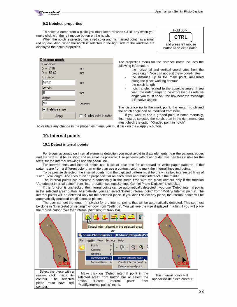
9.3 Notches properties To select a notch from a piece you must keep pressed CTRL key when you
make click with the left mouse button on the notch. When the notch is selected has a red color and his marked point has a small
red square. Also, when the notch is selected in the right side of the windows are displayed the notch properties.
The properties menu for the distance notch includes the following information:
- the horizontal and vertical coordinates from the piece origin. You can not edit these coordinates
- the distance up to the mark point, measured along the piece working contour
- the notch length - notch angle, related to the absolute angle. If you
want the notch angle to be expressed as relative angle you must check the box near the message « Relative angle»
The distance up to the mark point, the length notch and the notch angle can be modified from here.
If you want to add a graded point in notch manually, first must be selected the notch, than in the right menu you must check the option “Graded point in notch”
To validate any change in the properties menu, you must click on the « Apply » button.
10. Internal points 10.1 Detect internal points For bigger accuracy on internal elements detection you must avoid to draw elements near the patterns edges
and the text must be as short and as small as possible. Use patterns with fewer texts. Use pen less visible for the texts, for the internal drawings and the seam line.
For internal lines and internal points use black or blue pen for cardboard or white paper patterns. If the patterns are from a different color than white than use a contrast color to mark the internal lines and points.
To be precise detected, the internal points from the digitized pattern must be drawn as two intersected lines of 1 or 1.5 cm length. The lines must be perpendicular on each other and must intersect in the middle.
The internal points are detected automatically in the same time with the piece contour only if the function “Autodetect internal points” from “Interpretation settings\Settings Gemini Photo Digitizer” is checked.
If this function is unchecked, the internal points can be automatically detected if you use “Detect internal points in the selected area” button. Alternatively, you can select “Detect internal point” from “Modify/ Internal points”. The internal points will be detected only for the selected piece. If you didn’t select any piece, the internal points will be automatically detected on all detected pieces.
The user can set the length (in pixels) for the internal points that will be automatically detected. This set must be done in “Interpretation settings” window from “Settings”. You will see the size displayed in a hint if you will place the mouse cursor over the “Internal point length” track bar.
or
Select the piece with a mouse click inside its contour. The selected piece must have red contour.
Make click on “Detect internal point in the selected area” from button bar or select the option “Detect internal point” from “Modify/Internal points” menu.
The internal points will appear inside piece contour.
Hold down
and press left mouse
button to select a notch.
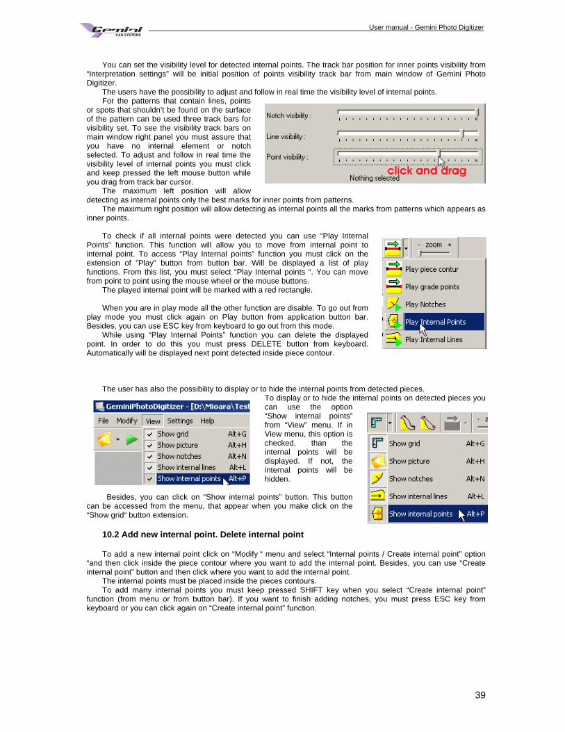
User manual - Gemini Photo Digitizer Plan
39
You can set the visibility level for detected internal points. The track bar position for inner points visibility from
“Interpretation settings” will be initial position of points visibility track bar from main window of Gemini Photo Digitizer.
The users have the possibility to adjust and follow in real time the visibility level of internal points. For the patterns that contain lines, points
or spots that shouldn’t be found on the surface of the pattern can be used three track bars for visibility set. To see the visibility track bars on main window right panel you must assure that you have no internal element or notch selected. To adjust and follow in real time the visibility level of internal points you must click and keep pressed the left mouse button while you drag from track bar cursor.
The maximum left position will allow detecting as internal points only the best marks for inner points from patterns.
The maximum right position will allow detecting as internal points all the marks from patterns which appears as inner points.
To check if all internal points were detected you can use “Play Internal
Points” function. This function will allow you to move from internal point to internal point. To access “Play Internal points” function you must click on the extension of ”Play” button from button bar. Will be displayed a list of play functions. From this list, you must select “Play Internal points “. You can move from point to point using the mouse wheel or the mouse buttons.
The played internal point will be marked with a red rectangle. When you are in play mode all the other function are disable. To go out from
play mode you must click again on Play button from application button bar. Besides, you can use ESC key from keyboard to go out from this mode.
While using “Play Internal Points” function you can delete the displayed point. In order to do this you must press DELETE button from keyboard. Automatically will be displayed next point detected inside piece contour.
The user has also the possibility to display or to hide the internal points from detected pieces.
To display or to hide the internal points on detected pieces you can use the option “Show internal points” from “View” menu. If in View menu, this option is checked, than the internal points will be displayed. If not, the internal points will be hidden.
Besides, you can click on “Show internal points” button. This button
can be accessed from the menu, that appear when you make click on the “Show grid“ button extension.
10.2 Add new internal point. Delete internal point To add a new internal point click on “Modify “ menu and select “Internal points / Create internal point” option
“and then click inside the piece contour where you want to add the internal point. Besides, you can use “Create internal point” button and then click where you want to add the internal point.
The internal points must be placed inside the pieces contours. To add many internal points you must keep pressed SHIFT key when you select “Create internal point”
function (from menu or from button bar). If you want to finish adding notches, you must press ESC key from keyboard or you can click again on “Create internal point” function.
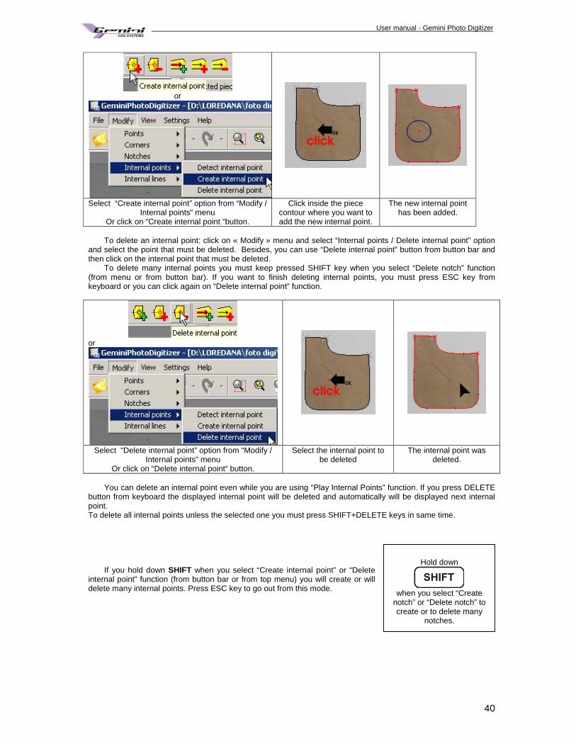
User manual - Gemini Photo Digitizer Plan
40
or
Select “Create internal point” option from “Modify / Internal points” menu
Or click on “Create internal point “button.
Click inside the piece contour where you want to add the new internal point.
The new internal point has been added.
To delete an internal point: click on « Modify » menu and select “Internal points / Delete internal point” option
and select the point that must be deleted. Besides, you can use “Delete internal point” button from button bar and then click on the internal point that must be deleted.
To delete many internal points you must keep pressed SHIFT key when you select “Delete notch” function (from menu or from button bar). If you want to finish deleting internal points, you must press ESC key from keyboard or you can click again on “Delete internal point” function.
or
Select “Delete internal point” option from “Modify / Internal points” menu
Or click on “Delete internal point“ button.
Select the internal point to be deleted
The internal point was deleted.
You can delete an internal point even while you are using “Play Internal Points” function. If you press DELETE
button from keyboard the displayed internal point will be deleted and automatically will be displayed next internal point. To delete all internal points unless the selected one you must press SHIFT+DELETE keys in same time.
If you hold down SHIFT when you select “Create internal point” or “Delete
internal point” function (from button bar or from top menu) you will create or will delete many internal points. Press ESC key to go out from this mode.
Hold down
when you select “Create
notch” or “Delete notch” to create or to delete many
notches.
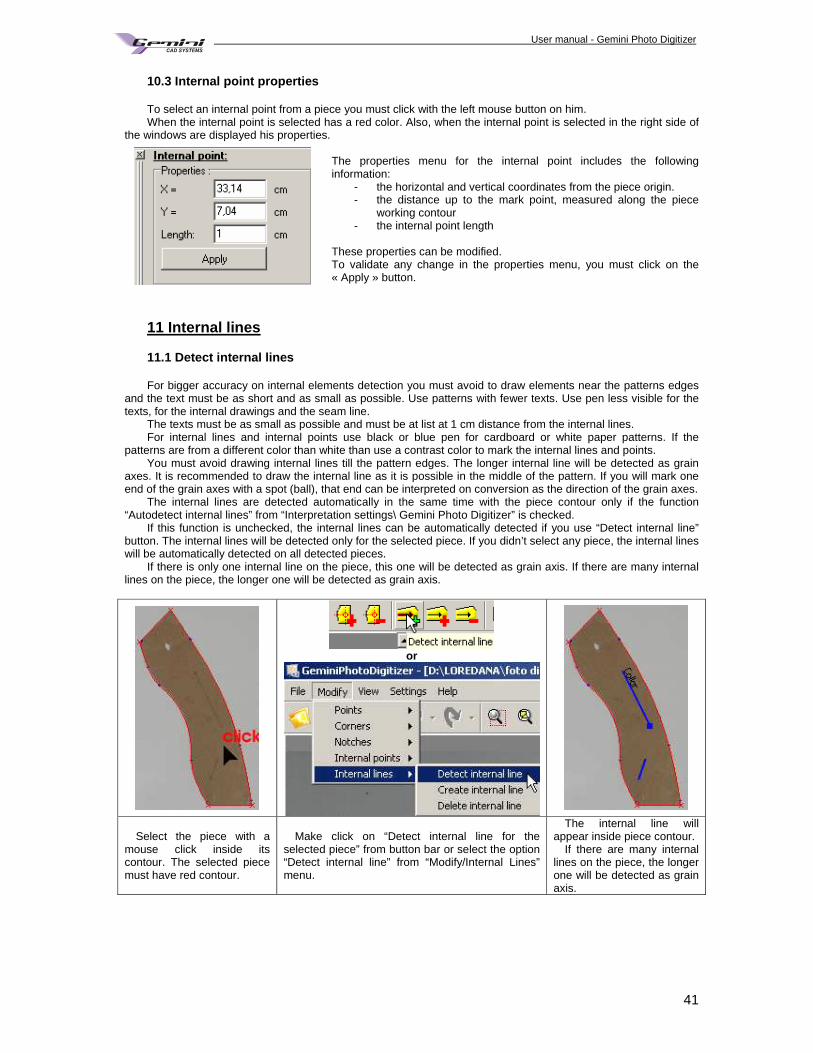
User manual - Gemini Photo Digitizer Plan
41
10.3 Internal point properties To select an internal point from a piece you must click with the left mouse button on him. When the internal point is selected has a red color. Also, when the internal point is selected in the right side of
the windows are displayed his properties. The properties menu for the internal point includes the following information:
- the horizontal and vertical coordinates from the piece origin. - the distance up to the mark point, measured along the piece
working contour - the internal point length
These properties can be modified. To validate any change in the properties menu, you must click on the « Apply » button.
11 Internal lines 11.1 Detect internal lines For bigger accuracy on internal elements detection you must avoid to draw elements near the patterns edges
and the text must be as short and as small as possible. Use patterns with fewer texts. Use pen less visible for the texts, for the internal drawings and the seam line.
The texts must be as small as possible and must be at list at 1 cm distance from the internal lines. For internal lines and internal points use black or blue pen for cardboard or white paper patterns. If the
patterns are from a different color than white than use a contrast color to mark the internal lines and points. You must avoid drawing internal lines till the pattern edges. The longer internal line will be detected as grain
axes. It is recommended to draw the internal line as it is possible in the middle of the pattern. If you will mark one end of the grain axes with a spot (ball), that end can be interpreted on conversion as the direction of the grain axes.
The internal lines are detected automatically in the same time with the piece contour only if the function “Autodetect internal lines” from “Interpretation settings\ Gemini Photo Digitizer” is checked.
If this function is unchecked, the internal lines can be automatically detected if you use “Detect internal line” button. The internal lines will be detected only for the selected piece. If you didn’t select any piece, the internal lines will be automatically detected on all detected pieces.
If there is only one internal line on the piece, this one will be detected as grain axis. If there are many internal lines on the piece, the longer one will be detected as grain axis.
or
Select the piece with a mouse click inside its contour. The selected piece must have red contour.
Make click on “Detect internal line for the selected piece” from button bar or select the option “Detect internal line” from “Modify/Internal Lines” menu.
The internal line will appear inside piece contour.
If there are many internal lines on the piece, the longer one will be detected as grain axis.
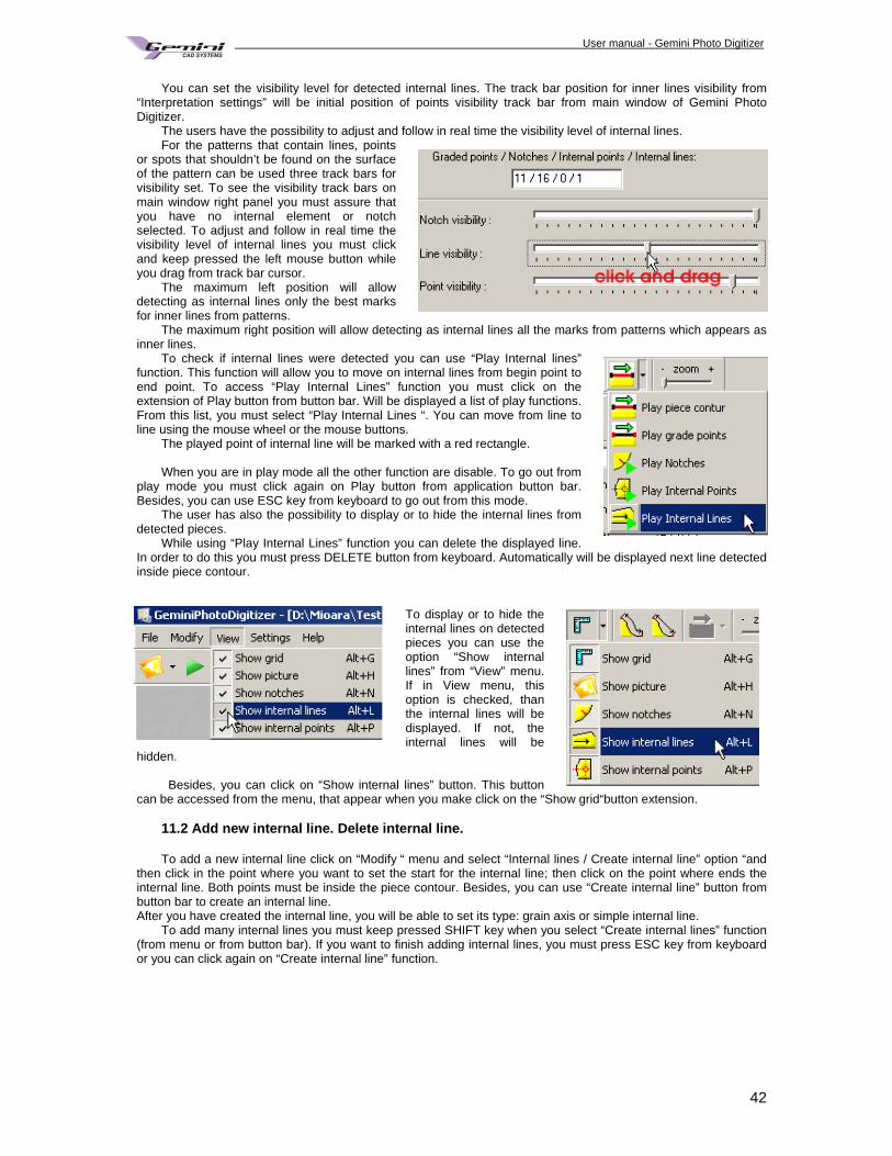
User manual - Gemini Photo Digitizer Plan
42
You can set the visibility level for detected internal lines. The track bar position for inner lines visibility from “Interpretation settings” will be initial position of points visibility track bar from main window of Gemini Photo Digitizer.
The users have the possibility to adjust and follow in real time the visibility level of internal lines. For the patterns that contain lines, points
or spots that shouldn’t be found on the surface of the pattern can be used three track bars for visibility set. To see the visibility track bars on main window right panel you must assure that you have no internal element or notch selected. To adjust and follow in real time the visibility level of internal lines you must click and keep pressed the left mouse button while you drag from track bar cursor.
The maximum left position will allow detecting as internal lines only the best marks for inner lines from patterns.
The maximum right position will allow detecting as internal lines all the marks from patterns which appears as inner lines.
To check if internal lines were detected you can use “Play Internal lines” function. This function will allow you to move on internal lines from begin point to end point. To access “Play Internal Lines” function you must click on the extension of Play button from button bar. Will be displayed a list of play functions. From this list, you must select “Play Internal Lines “. You can move from line to line using the mouse wheel or the mouse buttons.
The played point of internal line will be marked with a red rectangle. When you are in play mode all the other function are disable. To go out from
play mode you must click again on Play button from application button bar. Besides, you can use ESC key from keyboard to go out from this mode.
The user has also the possibility to display or to hide the internal lines from detected pieces.
While using “Play Internal Lines” function you can delete the displayed line. In order to do this you must press DELETE button from keyboard. Automatically will be displayed next line detected inside piece contour.
To display or to hide the internal lines on detected pieces you can use the option “Show internal lines” from “View” menu. If in View menu, this option is checked, than the internal lines will be displayed. If not, the internal lines will be
hidden. Besides, you can click on “Show internal lines” button. This button
can be accessed from the menu, that appear when you make click on the “Show grid“button extension. 11.2 Add new internal line. Delete internal line. To add a new internal line click on “Modify “ menu and select “Internal lines / Create internal line” option “and
then click in the point where you want to set the start for the internal line; then click on the point where ends the internal line. Both points must be inside the piece contour. Besides, you can use “Create internal line” button from button bar to create an internal line. After you have created the internal line, you will be able to set its type: grain axis or simple internal line.
To add many internal lines you must keep pressed SHIFT key when you select “Create internal lines” function (from menu or from button bar). If you want to finish adding internal lines, you must press ESC key from keyboard or you can click again on “Create internal line” function.
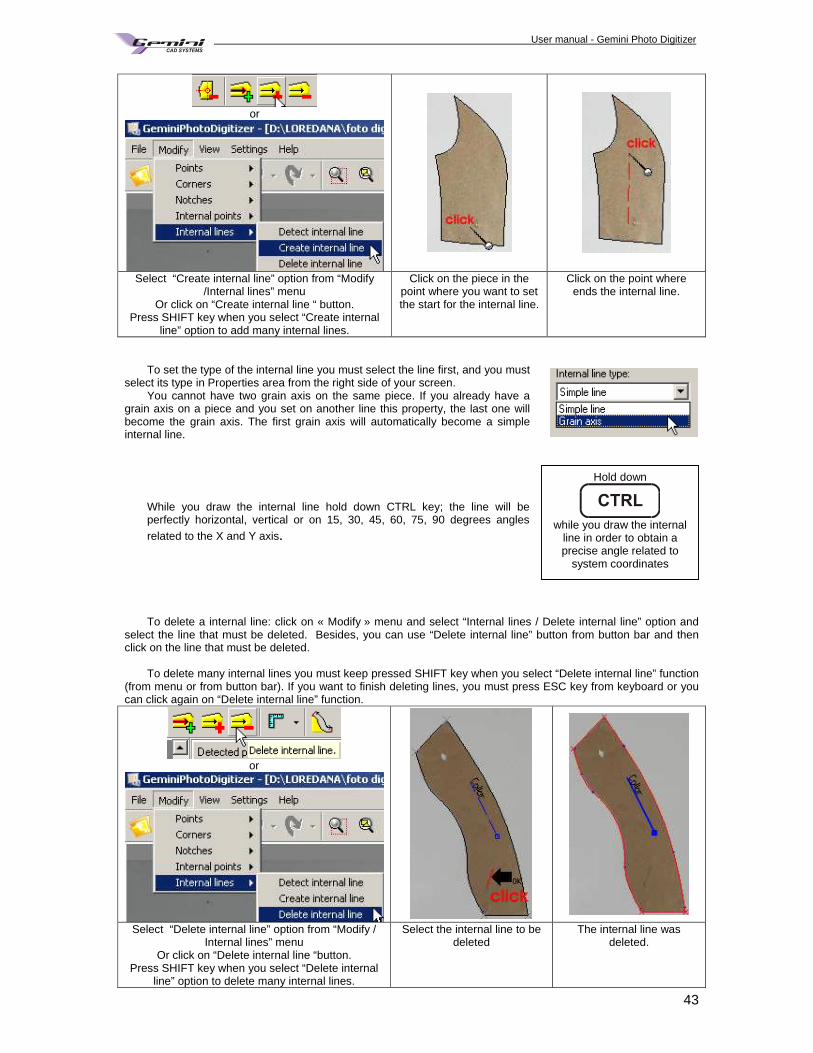
User manual - Gemini Photo Digitizer Plan
43
or
Select “Create internal line” option from “Modify /Internal lines” menu
Or click on “Create internal line “ button. Press SHIFT key when you select “Create internal
line” option to add many internal lines.
Click on the piece in the point where you want to set the start for the internal line.
Click on the point where ends the internal line.
To set the type of the internal line you must select the line first, and you must
select its type in Properties area from the right side of your screen. You cannot have two grain axis on the same piece. If you already have a
grain axis on a piece and you set on another line this property, the last one will become the grain axis. The first grain axis will automatically become a simple internal line.
While you draw the internal line hold down CTRL key; the line will be perfectly horizontal, vertical or on 15, 30, 45, 60, 75, 90 degrees angles
related to the X and Y axis.
To delete a internal line: click on « Modify » menu and select “Internal lines / Delete internal line” option and select the line that must be deleted. Besides, you can use “Delete internal line” button from button bar and then click on the line that must be deleted.
To delete many internal lines you must keep pressed SHIFT key when you select “Delete internal line” function
(from menu or from button bar). If you want to finish deleting lines, you must press ESC key from keyboard or you can click again on “Delete internal line” function.
or
Select “Delete internal line” option from “Modify / Internal lines” menu
Or click on “Delete internal line “button. Press SHIFT key when you select “Delete internal
line” option to delete many internal lines.
Select the internal line to be deleted
The internal line was deleted.
Hold down
while you draw the internal
line in order to obtain a precise angle related to
system coordinates
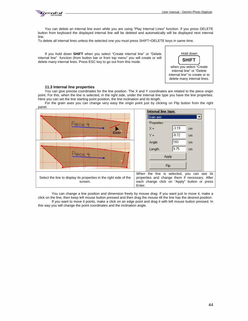
User manual - Gemini Photo Digitizer Plan
44
You can delete an internal line even while you are using “Play Internal Lines” function. If you press DELETE
button from keyboard the displayed internal line will be deleted and automatically will be displayed next internal line. To delete all internal lines unless the selected one you must press SHIFT+DELETE keys in same time.
If you hold down SHIFT when you select “Create internal line” or “Delete
internal line” function (from button bar or from top menu” you will create or will delete many internal lines. Press ESC key to go out from this mode.
11.3 Internal line properties You can give precise coordinates for the line position. The X and Y coordinates are related to the piece origin
point. For this, when the line is selected, in the right side, under the Internal line type you have the line properties. Here you can set the line starting point position, the line inclination and its length.
For the grain axes you can change very easy the origin point just by clicking on Flip button from the right panel.
Select the line to display its properties in the right side of the screen.
When the line is selected, you can see its properties and change them if necessary. After each change click on “Apply” button or press Enter.
You can change a line position and dimension freely by mouse drag. If you want just to move it, make a
click on the line, then keep left mouse button pressed and then drag the mouse till the line has the desired position. If you want to move it points, make a click on an edge point and drag it with left mouse button pressed. In
this way you will change the point coordinates and the inclination angle.
Hold down
when you select “Create internal line” or “Delete
internal line” to create or to delete many internal lines.
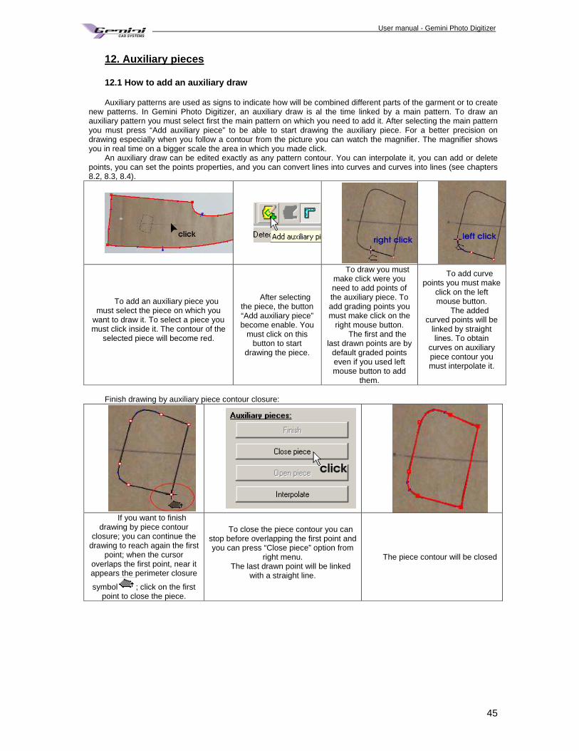
User manual - Gemini Photo Digitizer Plan
45
12. Auxiliary pieces 12.1 How to add an auxiliary draw Auxiliary patterns are used as signs to indicate how will be combined different parts of the garment or to create
new patterns. In Gemini Photo Digitizer, an auxiliary draw is al the time linked by a main pattern. To draw an auxiliary pattern you must select first the main pattern on which you need to add it. After selecting the main pattern you must press “Add auxiliary piece” to be able to start drawing the auxiliary piece. For a better precision on drawing especially when you follow a contour from the picture you can watch the magnifier. The magnifier shows you in real time on a bigger scale the area in which you made click.
An auxiliary draw can be edited exactly as any pattern contour. You can interpolate it, you can add or delete points, you can set the points properties, and you can convert lines into curves and curves into lines (see chapters 8.2, 8.3, 8.4).
To add an auxiliary piece you must select the piece on which you
want to draw it. To select a piece you must click inside it. The contour of the
selected piece will become red.
After selecting the piece, the button “Add auxiliary piece” become enable. You
must click on this button to start
drawing the piece.
To draw you must make click were you need to add points of the auxiliary piece. To add grading points you must make click on the
right mouse button. The first and the
last drawn points are by default graded points even if you used left mouse button to add
them.
To add curve points you must make
click on the left mouse button.
The added curved points will be
linked by straight lines. To obtain
curves on auxiliary piece contour you must interpolate it.
Finish drawing by auxiliary piece contour closure:
If you want to finish
drawing by piece contour closure; you can continue the
drawing to reach again the first point; when the cursor
overlaps the first point, near it appears the perimeter closure
symbol ; click on the first point to close the piece.
To close the piece contour you can stop before overlapping the first point and you can press “Close piece” option from
right menu. The last drawn point will be linked
with a straight line.
The piece contour will be closed
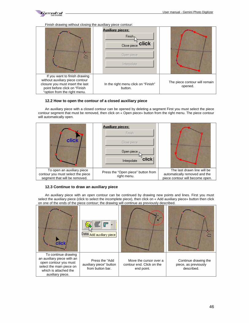
User manual - Gemini Photo Digitizer Plan
46
Finish drawing without closing the auxiliary piece contour:
If you want to finish drawing
without auxiliary piece contour closure you must insert the last
point before click on “Finish “option from the right menu.
In the right menu click on “Finish”
button.
The piece contour will remain opened.
12.2 How to open the contour of a closed auxiliary pi ece An auxiliary piece with a closed contour can be opened by deleting a segment First you must select the piece
contour segment that must be removed, then click on « Open piece» button from the right menu. The piece contour will automatically open.
To open an auxiliary piece
contour you must select the piece segment that will be removed.
Press the “Open piece” button from right menu.
The last drawn line will be automatically removed and the
piece contour will become open. 12.3 Continue to draw an auxiliary piece An auxiliary piece with an open contour can be continued by drawing new points and lines. First you must
select the auxiliary piece (click to select the incomplete piece), then click on « Add auxiliary piece» button then click on one of the ends of the piece contour; the drawing will continue as previously described.
To continue drawing
an auxiliary piece with an open contour you must
select the main piece on which is attached the
auxiliary piece.
Press the “Add auxiliary piece” button
from button bar.
Move the cursor over a contour end. Click on the
end point.
Continue drawing the piece, as previously
described.
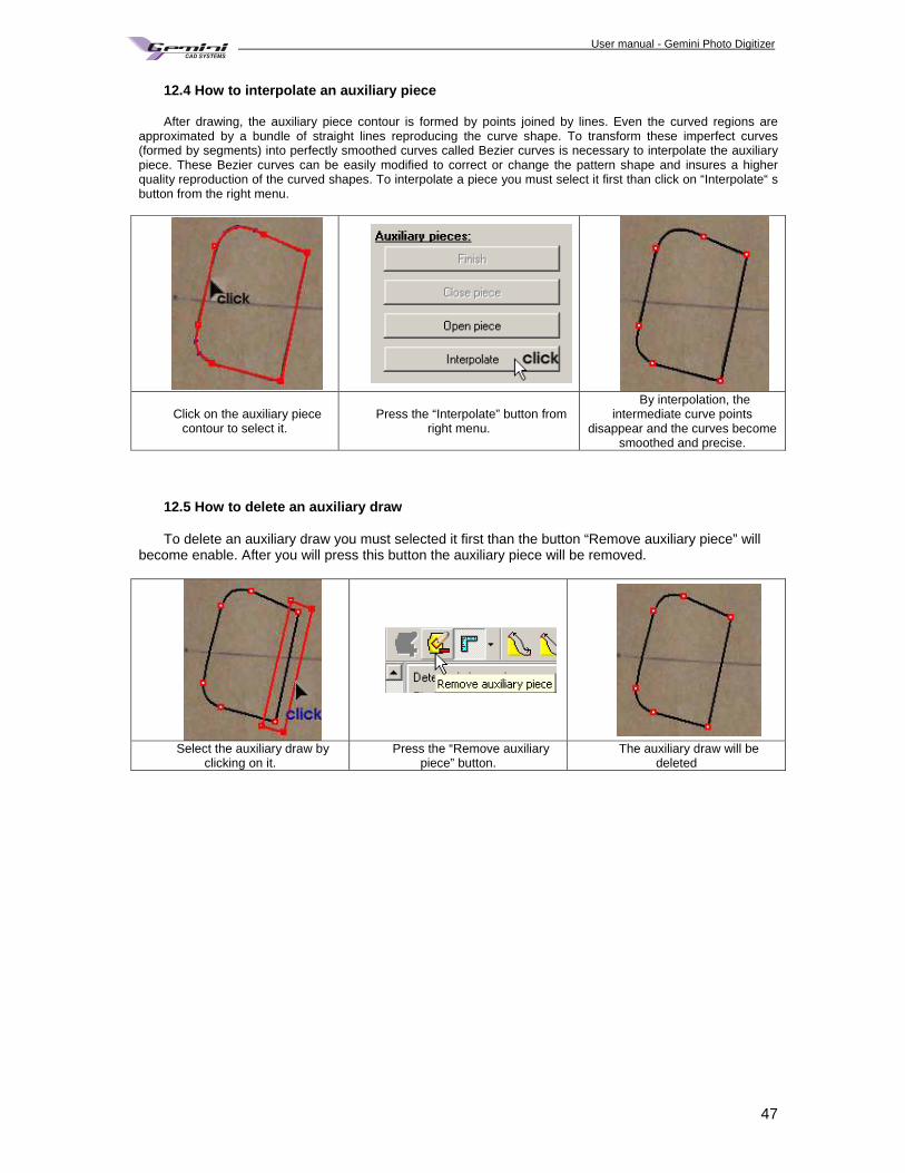
User manual - Gemini Photo Digitizer Plan
47
12.4 How to interpolate an auxiliary piece After drawing, the auxiliary piece contour is formed by points joined by lines. Even the curved regions are
approximated by a bundle of straight lines reproducing the curve shape. To transform these imperfect curves (formed by segments) into perfectly smoothed curves called Bezier curves is necessary to interpolate the auxiliary piece. These Bezier curves can be easily modified to correct or change the pattern shape and insures a higher quality reproduction of the curved shapes. To interpolate a piece you must select it first than click on “Interpolate“ s button from the right menu.
Click on the auxiliary piece contour to select it.
Press the “Interpolate” button from right menu.
By interpolation, the intermediate curve points
disappear and the curves become smoothed and precise.
12.5 How to delete an auxiliary draw To delete an auxiliary draw you must selected it first than the button “Remove auxiliary piece” will
become enable. After you will press this button the auxiliary piece will be removed.
Select the auxiliary draw by
clicking on it. Press the “Remove auxiliary
piece” button. The auxiliary draw will be
deleted
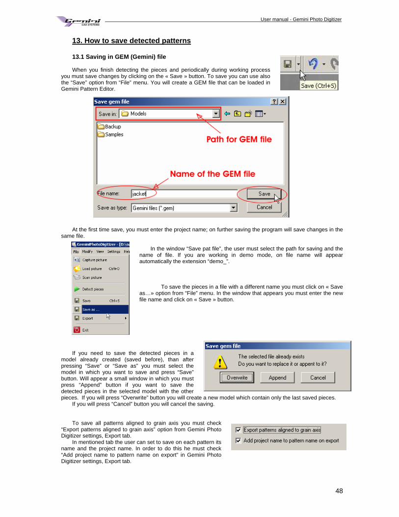
User manual - Gemini Photo Digitizer Plan
48
13. How to save detected patterns 13.1 Saving in GEM (Gemini) file When you finish detecting the pieces and periodically during working process
you must save changes by clicking on the « Save » button. To save you can use also the “Save” option from “File” menu. You will create a GEM file that can be loaded in Gemini Pattern Editor.
At the first time save, you must enter the project name; on further saving the program will save changes in the
same file. In the window “Save pat file”, the user must select the path for saving and the
name of file. If you are working in demo mode, on file name will appear automatically the extension “demo_”.
To save the pieces in a file with a different name you must click on « Save
as…» option from “File” menu. In the window that appears you must enter the new file name and click on « Save » button.
If you need to save the detected pieces in a model already created (saved before), than after pressing “Save” or “Save as” you must select the model in which you want to save and press “Save” button. Will appear a small window in which you must press “Append” button if you want to save the detected pieces in the selected model with the other pieces. If you will press “Overwrite” button you will create a new model which contain only the last saved pieces.
If you will press “Cancel” button you will cancel the saving. To save all patterns aligned to grain axis you must check
“Export patterns aligned to grain axis” option from Gemini Photo Digitizer settings, Export tab.
In mentioned tab the user can set to save on each pattern its name and the project name. In order to do this he must check “Add project name to pattern name on export” in Gemini Photo Digitizer settings, Export tab.
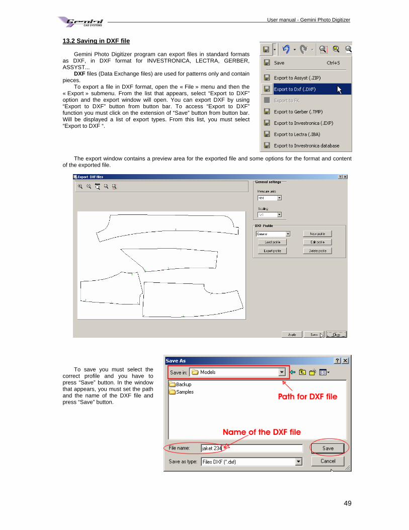
User manual - Gemini Photo Digitizer Plan
49
13.2 Saving in DXF file Gemini Photo Digitizer program can export files in standard formats
as DXF, in DXF format for INVESTRONICA, LECTRA, GERBER, ASSYST...
DXF files (Data Exchange files) are used for patterns only and contain pieces.
To export a file in DXF format, open the « File » menu and then the « Export » submenu. From the list that appears, select “Export to DXF” option and the export window will open. You can export DXF by using “Export to DXF” button from button bar. To access “Export to DXF” function you must click on the extension of “Save” button from button bar. Will be displayed a list of export types. From this list, you must select “Export to DXF “.
The export window contains a preview area for the exported file and some options for the format and content
of the exported file.
To save you must select the
correct profile and you have to press “Save” button. In the window that appears, you must set the path and the name of the DXF file and press “Save” button.
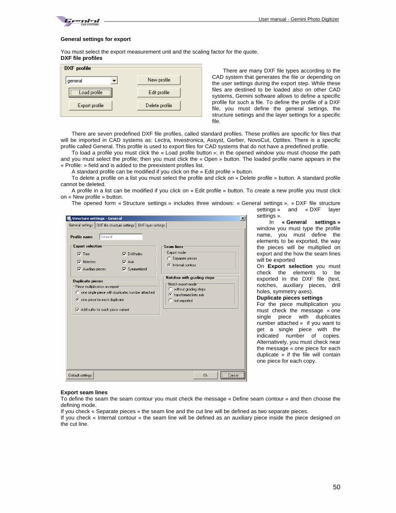
User manual - Gemini Photo Digitizer Plan
50
General settings for export You must select the export measurement unit and the scaling factor for the quote. DXF file profiles
There are many DXF file types according to the
CAD system that generates the file or depending on the user settings during the export step. While these files are destined to be loaded also on other CAD systems, Gemini software allows to define a specific profile for such a file. To define the profile of a DXF file, you must define the general settings, the structure settings and the layer settings for a specific file.
There are seven predefined DXF file profiles, called standard profiles. These profiles are specific for files that
will be imported in CAD systems as: Lectra, Investronica, Assyst, Gerber, NovoCut, Optitex. There is a specific profile called General. This profile is used to export files for CAD systems that do not have a predefined profile.
To load a profile you must click the « Load profile button »; in the opened window you must choose the path and you must select the profile; then you must click the « Open » button. The loaded profile name appears in the « Profile: » field and is added to the preexistent profiles list.
A standard profile can be modified if you click on the « Edit profile » button. To delete a profile on a list you must select the profile and click on « Delete profile » button. A standard profile
cannot be deleted. A profile in a list can be modified if you click on « Edit profile » button. To create a new profile you must click
on « New profile » button. The opened form « Structure settings » includes three windows: « General settings », « DXF file structure
settings » and « DXF layer settings ».
In « General settings » window you must type the profile name, you must define the elements to be exported, the way the pieces will be multiplied on export and the how the seam lines will be exported On Export selection you must check the elements to be exported in the DXF file (text, notches, auxiliary pieces, drill holes, symmetry axes). Duplicate pieces settings For the piece multiplication you must check the message « one single piece with duplicates number attached » if you want to get a single piece with the indicated number of copies. Alternatively, you must check near the message « one piece for each duplicate » if the file will contain one piece for each copy.
Export seam lines To define the seam the seam contour you must check the message « Define seam contour » and then choose the defining mode. If you check « Separate pieces » the seam line and the cut line will be defined as two separate pieces. If you check « Internal contour » the seam line will be defined as an auxiliary piece inside the piece designed on the cut line.
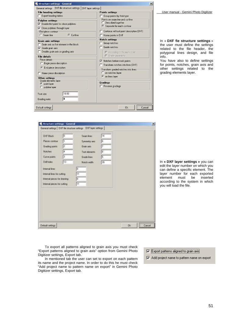
User manual - Gemini Photo Digitizer Plan
51
In « DXF fie structure settings » the user must define the settings related to the file header, the polygonal lines design, and file info. You have also to define settings for points, notches, grain axis and other settings related to the grading elements layer.
In « DXF layer settings » you can edit the layer number on which you can define a specific element. The layer number for each exported element must be inserted according to the system in which you will load the file.
To export all patterns aligned to grain axis you must check
“Export patterns aligned to grain axis” option from Gemini Photo Digitizer settings, Export tab.
In mentioned tab the user can set to export on each pattern its name and the project name. In order to do this he must check “Add project name to pattern name on export” in Gemini Photo Digitizer settings, Export tab.
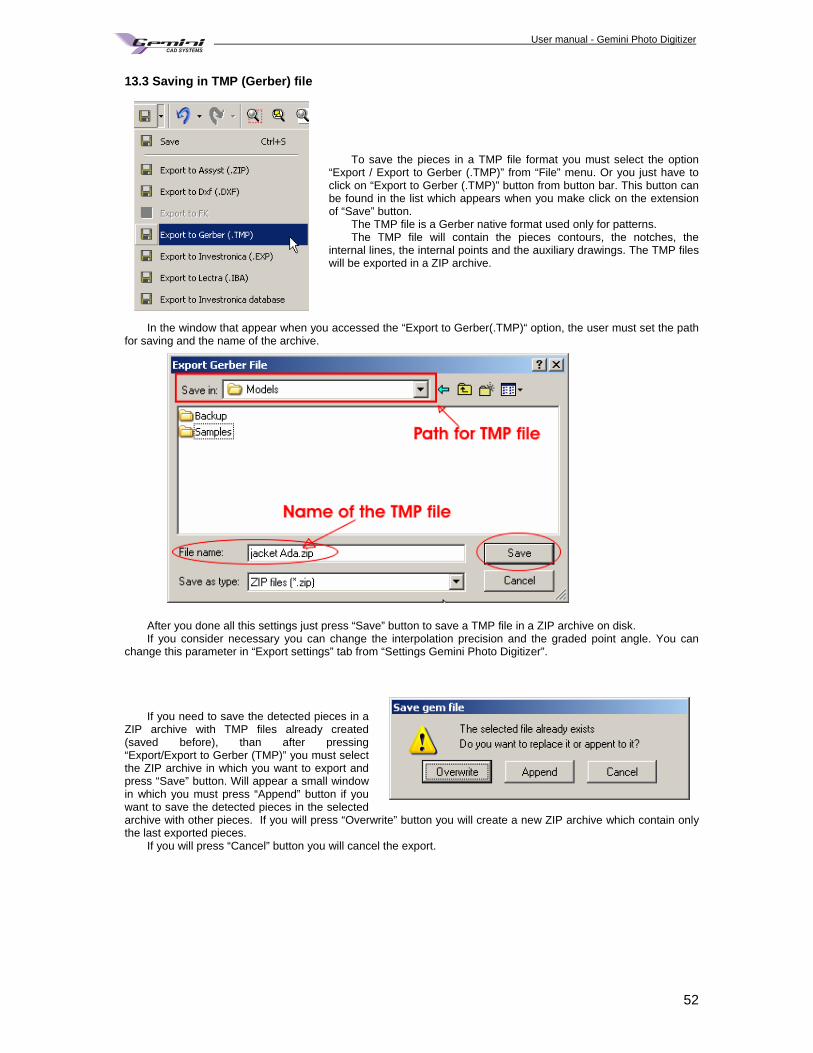
User manual - Gemini Photo Digitizer Plan
52
13.3 Saving in TMP (Gerber) file
To save the pieces in a TMP file format you must select the option
“Export / Export to Gerber (.TMP)” from “File” menu. Or you just have to click on “Export to Gerber (.TMP)” button from button bar. This button can be found in the list which appears when you make click on the extension of “Save” button.
The TMP file is a Gerber native format used only for patterns. The TMP file will contain the pieces contours, the notches, the
internal lines, the internal points and the auxiliary drawings. The TMP files will be exported in a ZIP archive.
In the window that appear when you accessed the “Export to Gerber(.TMP)“ option, the user must set the path for saving and the name of the archive.
After you done all this settings just press “Save” button to save a TMP file in a ZIP archive on disk. If you consider necessary you can change the interpolation precision and the graded point angle. You can
change this parameter in “Export settings” tab from “Settings Gemini Photo Digitizer”.
If you need to save the detected pieces in a
ZIP archive with TMP files already created (saved before), than after pressing “Export/Export to Gerber (TMP)” you must select the ZIP archive in which you want to export and press “Save” button. Will appear a small window in which you must press “Append” button if you want to save the detected pieces in the selected archive with other pieces. If you will press “Overwrite” button you will create a new ZIP archive which contain only the last exported pieces.
If you will press “Cancel” button you will cancel the export.
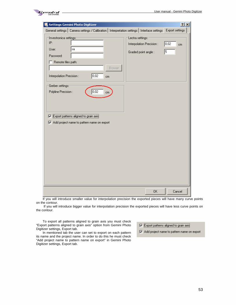
User manual - Gemini Photo Digitizer Plan
53
If you will introduce smaller value for interpolation precision the exported pieces will have many curve points
on the contour. If you will introduce bigger value for interpolation precision the exported pieces will have less curve points on
the contour. To export all patterns aligned to grain axis you must check
“Export patterns aligned to grain axis” option from Gemini Photo Digitizer settings, Export tab.
In mentioned tab the user can set to export on each pattern its name and the project name. In order to do this he must check “Add project name to pattern name on export” in Gemini Photo Digitizer settings, Export tab.
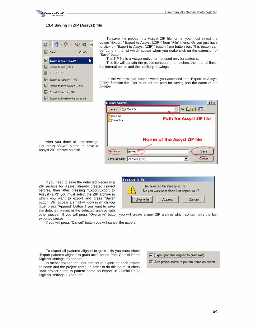
User manual - Gemini Photo Digitizer Plan
54
13.4 Saving in ZIP (Assyst) file
To save the pieces in a Assyst ZIP file format you must select the option “Export / Export to Assyst (.ZIP)” from “File” menu. Or you just have to click on “Export to Assyst (.ZIP)” button from button bar. This button can be found in the list which appear when you make click on the extension of “Save” button.
The ZIP file is a Assyst native format used only for patterns. This file will contain the pieces contours, the notches, the internal lines,
the internal points and the auxiliary drawings. In the window that appear when you accessed the “Export to Assyst
(.ZIP)“ function the user must set the path for saving and the name of the archive.
After you done all this settings
just press “Save” button to save a Assyst ZIP archive on disk.
If you need to save the detected pieces in a
ZIP archive for Assyst already created (saved before), than after pressing “Export/Export to Assyst (ZIP)” you must select the ZIP archive in which you want to export and press “Save” button. Will appear a small window in which you must press “Append” button if you want to save the detected pieces in the selected archive with other pieces. If you will press “Overwrite” button you will create a new ZIP archive which contain only the last exported pieces.
If you will press “Cancel” button you will cancel the export.
To export all patterns aligned to grain axis you must check
“Export patterns aligned to grain axis” option from Gemini Photo Digitizer settings, Export tab.
In mentioned tab the user can set to export on each pattern its name and the project name. In order to do this he must check “Add project name to pattern name on export” in Gemini Photo Digitizer settings, Export tab.
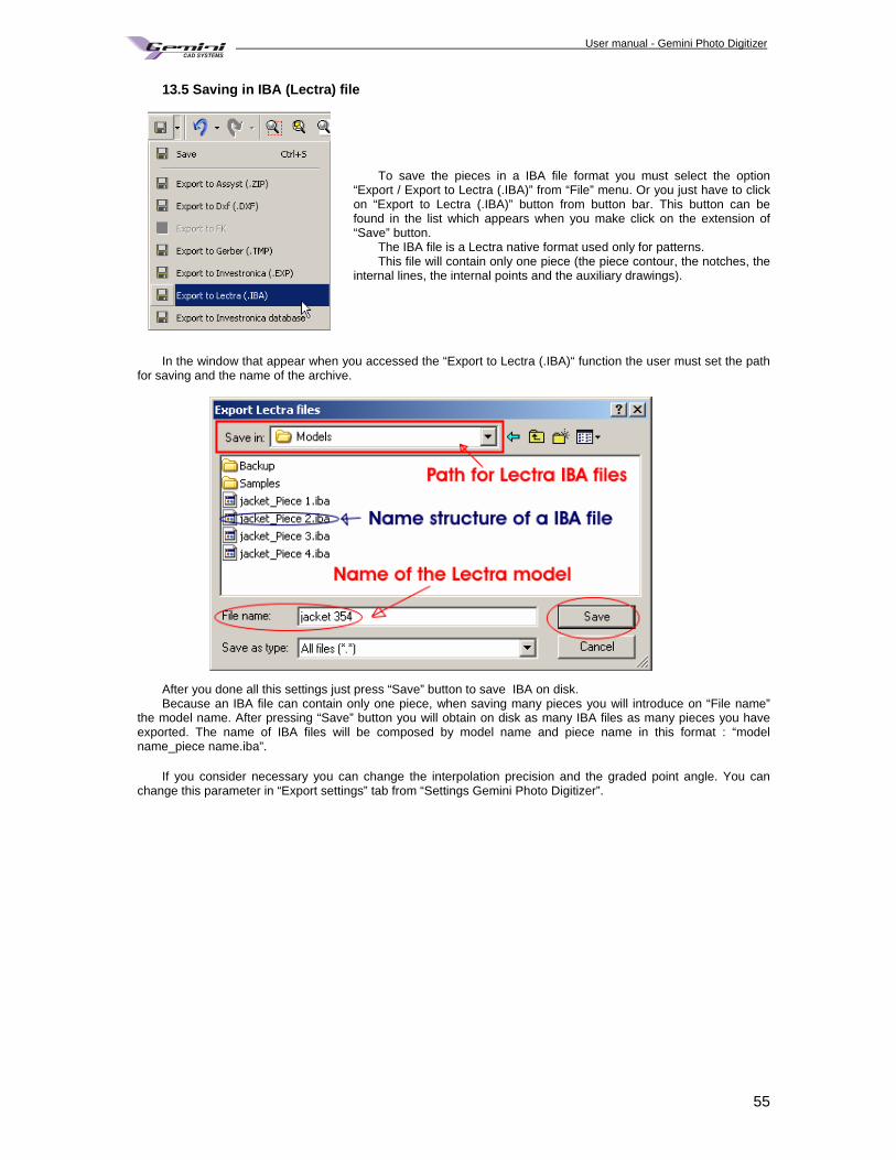
User manual - Gemini Photo Digitizer Plan
55
13.5 Saving in IBA (Lectra) file
To save the pieces in a IBA file format you must select the option
“Export / Export to Lectra (.IBA)” from “File” menu. Or you just have to click on “Export to Lectra (.IBA)” button from button bar. This button can be found in the list which appears when you make click on the extension of “Save” button.
The IBA file is a Lectra native format used only for patterns. This file will contain only one piece (the piece contour, the notches, the
internal lines, the internal points and the auxiliary drawings).
In the window that appear when you accessed the “Export to Lectra (.IBA)“ function the user must set the path
for saving and the name of the archive. After you done all this settings just press “Save” button to save IBA on disk. Because an IBA file can contain only one piece, when saving many pieces you will introduce on “File name”
the model name. After pressing “Save” button you will obtain on disk as many IBA files as many pieces you have exported. The name of IBA files will be composed by model name and piece name in this format : “model name_piece name.iba”.
If you consider necessary you can change the interpolation precision and the graded point angle. You can
change this parameter in “Export settings” tab from “Settings Gemini Photo Digitizer”.
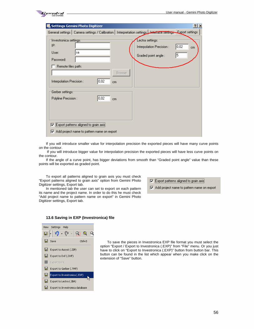
User manual - Gemini Photo Digitizer Plan
56
If you will introduce smaller value for interpolation precision the exported pieces will have many curve points
on the contour. If you will introduce bigger value for interpolation precision the exported pieces will have less curve points on
the contour. If the angle of a curve point, has bigger deviations from smooth than “Graded point angle” value than these
points will be exported as graded point. To export all patterns aligned to grain axis you must check
“Export patterns aligned to grain axis” option from Gemini Photo Digitizer settings, Export tab.
In mentioned tab the user can set to export on each pattern its name and the project name. In order to do this he must check “Add project name to pattern name on export” in Gemini Photo Digitizer settings, Export tab.
13.6 Saving in EXP (Investronica) file
To save the pieces in Investronica EXP file format you must select the
option “Export / Export to Investronica (.EXP)” from “File” menu. Or you just have to click on “Export to Investronica (.EXP)” button from button bar. This button can be found in the list which appear when you make click on the extension of “Save” button.
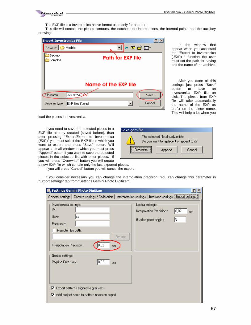
User manual - Gemini Photo Digitizer Plan
57
The EXP file is a Investronica native format used only for patterns. This file will contain the pieces contours, the notches, the internal lines, the internal points and the auxiliary
drawings. In the window that
appear when you accessed the “Export to Investronica (.EXP) “ function the user must set the path for saving and the name of the archive.
After you done all this
settings just press “Save” button to save an Investronica EXP file on disk. The pieces from EXP file will take automatically the name of the EXP as prefix on the piece name. This will help a lot when you
load the pieces in Investronica. If you need to save the detected pieces in a
EXP file already created (saved before), than after pressing “Export/Export to Investronica (EXP)” you must select the EXP file in which you want to export and press “Save” button. Will appear a small window in which you must press “Append” button if you want to save the detected pieces in the selected file with other pieces. If you will press “Overwrite” button you will create a new EXP file which contain only the last exported pieces.
If you will press “Cancel” button you will cancel the export.
If you consider necessary you can change the interpolation precision. You can change this parameter in “Export settings” tab from “Settings Gemini Photo Digitizer”.
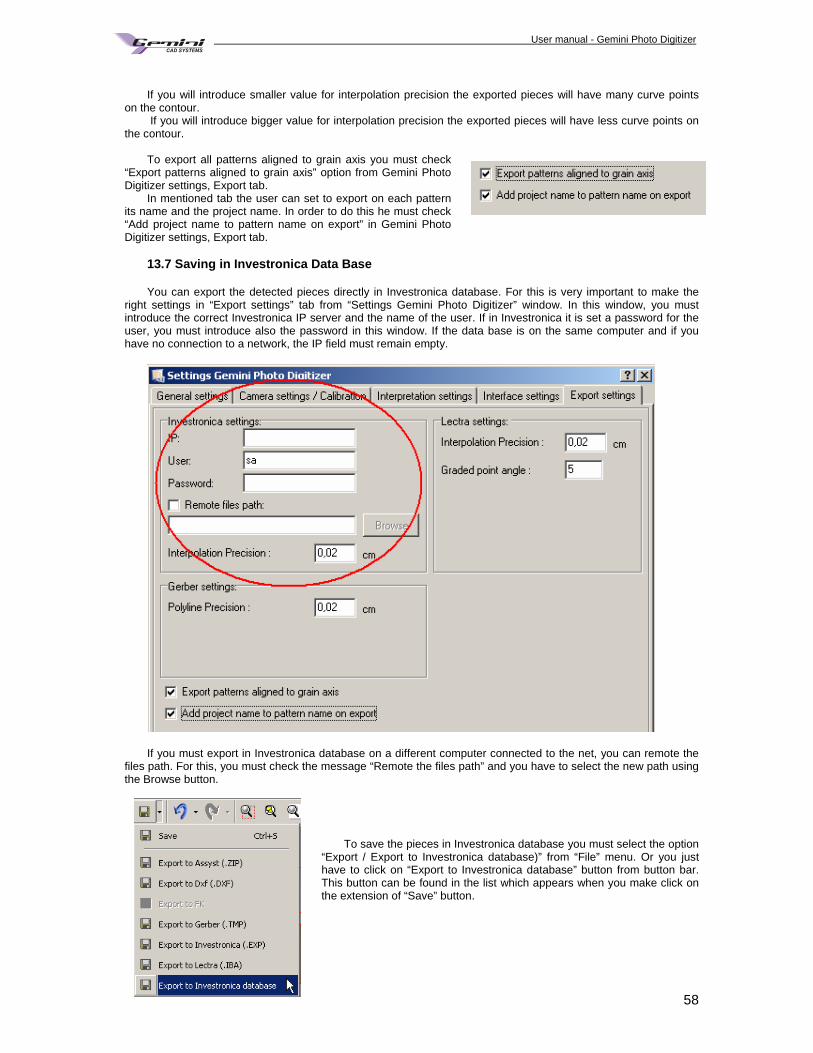
User manual - Gemini Photo Digitizer Plan
58
If you will introduce smaller value for interpolation precision the exported pieces will have many curve points
on the contour. If you will introduce bigger value for interpolation precision the exported pieces will have less curve points on
the contour. To export all patterns aligned to grain axis you must check
“Export patterns aligned to grain axis” option from Gemini Photo Digitizer settings, Export tab.
In mentioned tab the user can set to export on each pattern its name and the project name. In order to do this he must check “Add project name to pattern name on export” in Gemini Photo Digitizer settings, Export tab.
13.7 Saving in Investronica Data Base You can export the detected pieces directly in Investronica database. For this is very important to make the
right settings in “Export settings” tab from “Settings Gemini Photo Digitizer” window. In this window, you must introduce the correct Investronica IP server and the name of the user. If in Investronica it is set a password for the user, you must introduce also the password in this window. If the data base is on the same computer and if you have no connection to a network, the IP field must remain empty.
If you must export in Investronica database on a different computer connected to the net, you can remote the
files path. For this, you must check the message “Remote the files path” and you have to select the new path using the Browse button.
To save the pieces in Investronica database you must select the option
“Export / Export to Investronica database)” from “File” menu. Or you just have to click on “Export to Investronica database” button from button bar. This button can be found in the list which appears when you make click on the extension of “Save” button.
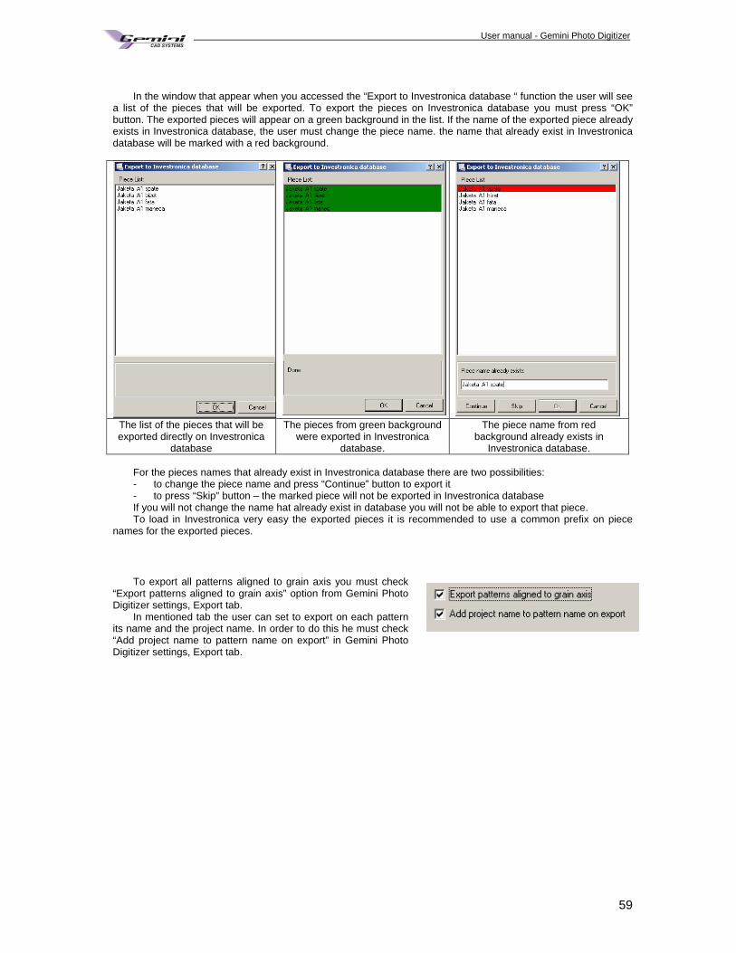
User manual - Gemini Photo Digitizer Plan
59
In the window that appear when you accessed the “Export to Investronica database “ function the user will see
a list of the pieces that will be exported. To export the pieces on Investronica database you must press “OK” button. The exported pieces will appear on a green background in the list. If the name of the exported piece already exists in Investronica database, the user must change the piece name. the name that already exist in Investronica database will be marked with a red background.
The list of the pieces that will be exported directly on Investronica
database
The pieces from green background were exported in Investronica
database.
The piece name from red background already exists in
Investronica database. For the pieces names that already exist in Investronica database there are two possibilities: - to change the piece name and press “Continue” button to export it - to press “Skip” button – the marked piece will not be exported in Investronica database If you will not change the name hat already exist in database you will not be able to export that piece. To load in Investronica very easy the exported pieces it is recommended to use a common prefix on piece
names for the exported pieces.
To export all patterns aligned to grain axis you must check
“Export patterns aligned to grain axis” option from Gemini Photo Digitizer settings, Export tab.
In mentioned tab the user can set to export on each pattern its name and the project name. In order to do this he must check “Add project name to pattern name on export” in Gemini Photo Digitizer settings, Export tab.
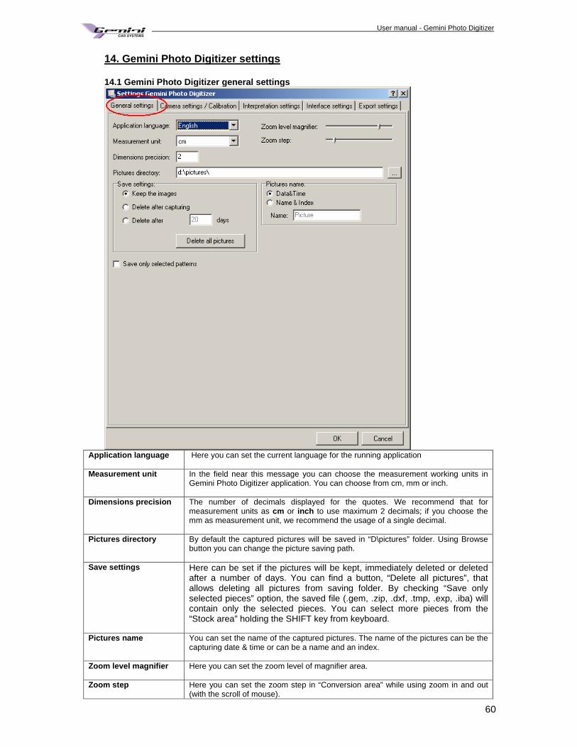
User manual - Gemini Photo Digitizer Plan
60
14. Gemini Photo Digitizer settings 14.1 Gemini Photo Digitizer general settings
Application language Here you can set the current language for the running application
Measurement unit In the field near this message you can choose the measurement working units in
Gemini Photo Digitizer application. You can choose from cm, mm or inch.
Dimensions precision The number of decimals displayed for the quotes. We recommend that for measurement units as cm or inch to use maximum 2 decimals; if you choose the mm as measurement unit, we recommend the usage of a single decimal.
Pictures directory By default the captured pictures will be saved in “D\pictures” folder. Using Browse button you can change the picture saving path.
Save settings Here can be set if the pictures will be kept, immediately deleted or deleted after a number of days. You can find a button, “Delete all pictures”, that allows deleting all pictures from saving folder. By checking “Save only selected pieces” option, the saved file (.gem, .zip, .dxf, .tmp, .exp, .iba) will contain only the selected pieces. You can select more pieces from the “Stock area” holding the SHIFT key from keyboard.
Pictures name You can set the name of the captured pictures. The name of the pictures can be the capturing date & time or can be a name and an index.
Zoom level magnifier Here you can set the zoom level of magnifier area.
Zoom step Here you can set the zoom step in “Conversion area” while using zoom in and out (with the scroll of mouse).
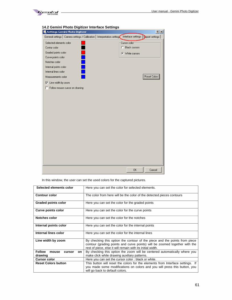
User manual - Gemini Photo Digitizer Plan
61
14.2 Gemini Photo Digitizer Interface Settings
In this window, the user can set the used colors for the captured pictures.
Selected elements color Here you can set the color for selected elements.
Contour color The color from here will be the color of the detected pieces contours
Graded points color Here you can set the color for the graded points
Curve points color Here you can set the color for the curve points
Notches color Here you can set the color for the notches
Internal points color Here you can set the color for the internal points
Internal lines color Here you can set the color for the internal lines
Line width by zoom By checking this option the contour of the piece and the points from piece contour (grading points and curve points) will be zoomed together with the rest of piece, else it will remain with its initial width.
Follow mouse cursor on drawing
By checking this option the zoom will be centered automatically where you make click while drawing auxiliary patterns.
Cursor color Here you can set the cursor color : black or white. Reset Colors button This button will reset the colors for the elements from Interface settings. If
you made some modifications on colors and you will press this button, you will go back to default colors.
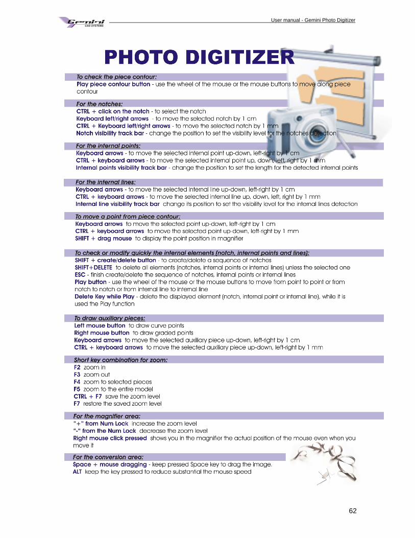
User manual - Gemini Photo Digitizer Plan
62
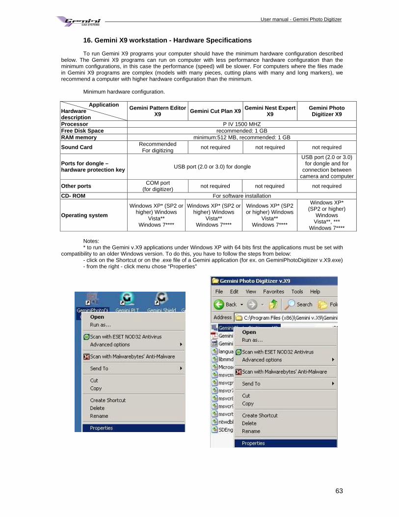
User manual - Gemini Photo Digitizer Plan
63
16. Gemini X9 workstation - Hardware Specifications
To run Gemini X9 programs your computer should have the minimum hardware configuration described below. The Gemini X9 programs can run on computer with less performance hardware configuration than the minimum configurations, in this case the performance (speed) will be slower. For computers where the files made in Gemini X9 programs are complex (models with many pieces, cutting plans with many and long markers), we recommend a computer with higher hardware configuration than the minimum. Minimum hardware configuration.
Application Hardware description
Gemini Pattern Editor X9 Gemini Cut Plan X9 Gemini Nest Expert
X9 Gemini Photo Digitizer X9
Processor P IV 1500 MHZ Free Disk Space recommended: 1 GB RAM memory minimum:512 MB, recommended: 1 GB
Sound Card Recommended For digitizing not required not required not required
Ports for dongle – hardware protection key USB port (2.0 or 3.0) for dongle
USB port (2.0 or 3.0) for dongle and for
connection between camera and computer
Other ports COM port (for digitizer) not required not required not required
CD- ROM For software installation
Operating system
Windows XP* (SP2 or higher) Windows
Vista** Windows 7****
Windows XP* (SP2 or higher) Windows
Vista** Windows 7****
Windows XP* (SP2 or higher) Windows
Vista** Windows 7****
Windows XP* (SP2 or higher)
Windows Vista**, ***
Windows 7**** Notes: * to run the Gemini v.X9 applications under Windows XP with 64 bits first the applications must be set with
compatibility to an older Windows version. To do this, you have to follow the steps from below: - click on the Shortcut or on the .exe file of a Gemini application (for ex. on GeminiPhotoDigitizer v.X9.exe) - from the right - click menu chose “Properties”
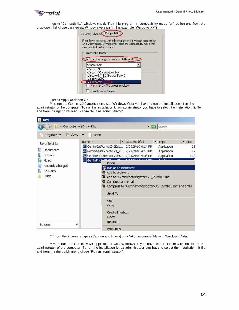
User manual - Gemini Photo Digitizer Plan
64
- go to “Compatibility” window, check “Run this program in compatibility mode for:” option and from the drop-down list chose the newest Windows version (in this example “Windows XP”)
- press Apply and then OK ** to run the Gemini v.X9 applications with Windows Vista you have to run the installation kit as the
administrator of the computer. To run the installation kit as administrator you have to select the installation kit file and from the right-click menu chose “Run as administrator”:
*** from the 2 camera types (Cannon and Nikon) only Nikon is compatible with Windows Vista. **** to run the Gemini v.X9 applications with Windows 7 you have to run the installation kit as the administrator of the computer. To run the installation kit as administrator you have to select the installation kit file and from the right-click menu chose “Run as administrator”:
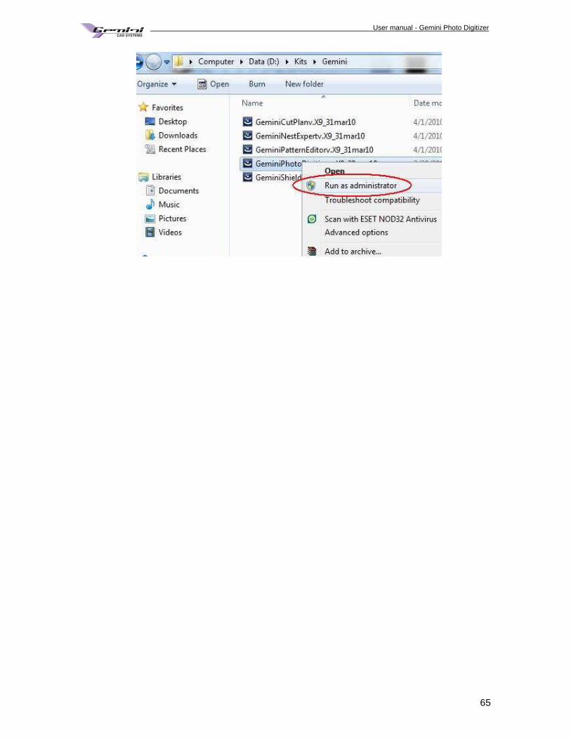
User manual - Gemini Photo Digitizer Plan
65