GEM-SERIES ESVI -...
52
Instruction manual for NSM Phonographs GEM-SERIES ESVI part-no.: 180 079
Transcript of GEM-SERIES ESVI -...

Instruction manualfor
NSM Phonographs
GEM-SERIES ESVI
part-no.: 180 079

Instruction manual ESVI-phonographsii
Copyright-Note All rights reserved.Copyright NSM MUSIC GmbH – October 2000No part of this publication may be reproduced, stored in aretrieval system, or transmitted, in any form or by anymeans, electronic, mechanical, photocopying, recording,or otherwise, without the prior written consent ofNSM MUSIC GmbH • 55411 Bingen/Rhein • ImTiergarten 20-30 • Germany.
Disclaimer NSM MUSIC GmbH and all of its subsidiaries makes norepresentation or warranty with respect of the adequacy ofthis documentation or the procedures which it describesfor any particular purpose or with respect to its adequacyto produce any particular result. In no event shall NSMMUSIC GmbH, its employees, its contractors or theauthors of this documentation be liable for special, direct,indirect or consequential damages, losses, costs, charges,claims, demands, or claim for lost profits, fees orexpenses of any nature or kind.
Subject to technical modification without obligation tomodify equipment already delivered!
Our Internet-address: http://www.nsmmusic.com
Version: 1.03/2000
Date: 30/10/2000
Part number of this manual:180 079
For quick orientation
Instruction manual ESVI-phonographs iii
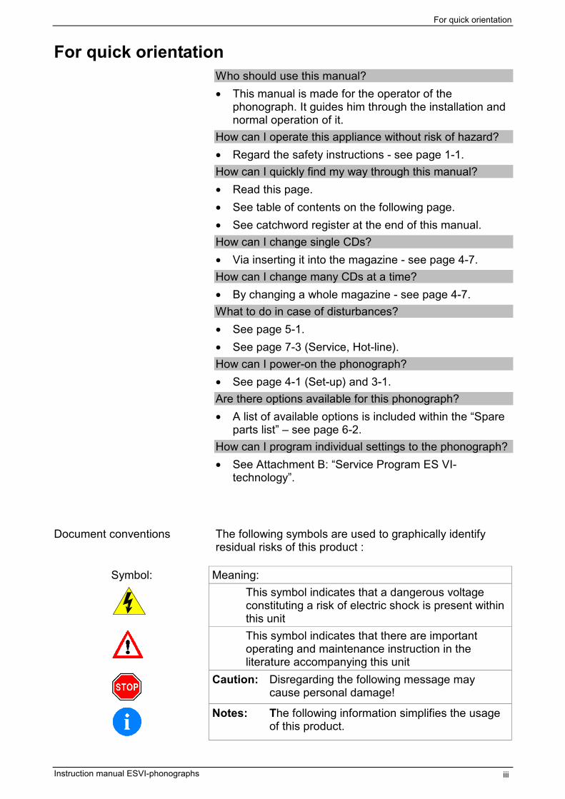
For quick orientationWho should use this manual?• This manual is made for the operator of the
phonograph. It guides him through the installation andnormal operation of it.
How can I operate this appliance without risk of hazard?• Regard the safety instructions - see page 1-1.How can I quickly find my way through this manual?• Read this page.• See table of contents on the following page.• See catchword register at the end of this manual.How can I change single CDs?• Via inserting it into the magazine - see page 4-7.How can I change many CDs at a time?• By changing a whole magazine - see page 4-7.What to do in case of disturbances?• See page 5-1.• See page 7-3 (Service, Hot-line).How can I power-on the phonograph?• See page 4-1 (Set-up) and 3-1.Are there options available for this phonograph?• A list of available options is included within the “Spare
parts list” – see page 6-2.How can I program individual settings to the phonograph?• See Attachment B: “Service Program ES VI-
technology”.
Document conventions The following symbols are used to graphically identifyresidual risks of this product :
Symbol: Meaning:This symbol indicates that a dangerous voltage constituting a risk of electric shock is present within this unitThis symbol indicates that there are important operating and maintenance instruction in the literature accompanying this unit
Caution: Disregarding the following message maycause personal damage!
Notes: The following information simplifies the usageof this product.

Table of contents
Instruction manual ESVI-phonographsiv
This page left blank intentionally.
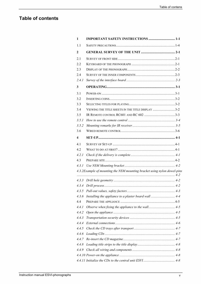
Table of contens
Instruction manual ESVI-phonographs v
Table of contents
1 IMPORTANT SAFETY INSTRUCTIONS ............................... 1-1
1.1 SAFETY PRECAUTIONS.....................................................................1-4
2 GENERAL SURVEY OF THE UNIT ........................................ 2-1
2.1 SURVEY OF FRONT SIDE...................................................................2-12.2 KEYBOARD OF THE PHONOGRAPH ...................................................2-12.3 DISPLAY OF THE PHONOGRAPH........................................................2-22.4 SURVEY OF THE INNER COMPONENTS..............................................2-32.4.1 Survey of the interface board ......................................................... 2-3
3 OPERATING................................................................................ 3-1
3.1 POWER-ON ......................................................................................3-13.2 INSERTING COINS.............................................................................3-23.3 SELECTING TITLES FOR PLAYING......................................................3-23.4 VIEWING THE TITLE SHEETS IN THE TITLE DISPLAY ..........................3-23.5 IR REMOTE CONTROL RC601 AND RC 602 ....................................3-33.5.1 How to use the remote control ....................................................... 3-43.5.2 Mounting remarks for IR receiver.................................................. 3-53.6 WIRED REMOTE CONTROL...............................................................3-6
4 SET-UP.......................................................................................... 4-1
4.1 SURVEY OF SET-UP .........................................................................4-14.2 WHAT TO DO AT FIRST? ...................................................................4-14.2.1 Check if the delivery is complete .................................................... 4-14.3 PREPARE SITE..................................................................................4-24.3.1 Use NSM Mounting bracket ........................................................... 4-24.3.2Example of mounting the NSM mounting bracket using nylon dowel-pins................................................................................................................... 4-24.3.3 Drill hole geometry ........................................................................ 4-24.3.4 Drill process................................................................................... 4-24.3.5 Pull-out values, safety factors ........................................................ 4-34.3.6 Installing the appliance to a plaster board wall ............................ 4-44.4 PREPARE THE APPLIANCE ................................................................4-54.4.1 Observe when fixing the appliance to the wall............................... 4-54.4.2 Open the appliance ........................................................................ 4-54.4.3 Transportation security devices ..................................................... 4-54.4.4 External connections ...................................................................... 4-64.4.5 Check the CD trays after transport ................................................ 4-74.4.6 Loading CDs .................................................................................. 4-74.4.7 Re-insert the CD magazine............................................................. 4-74.4.8 Loading title strips to the title display............................................ 4-84.4.9 Check all wiring and components .................................................. 4-84.4.10 Power-on the appliance ................................................................. 4-84.4.11 Initialize the CDs to the central unit ESVI ..................................... 4-8

Table of contens
Instruction manual ESVI-phonographsvi
5 DISTURBANCES......................................................................... 5-1
5.1 AVOIDING DISTURBANCES...............................................................5-15.2 REPORTS ON THE DISPLAY...............................................................5-25.3 REPLACING LINE FUSES ...................................................................5-35.4 REPLACING THE SECONDARY FUSES ................................................5-3
6 SPARE PARTS CATALOG........................................................ 6-1
7 APPENDIX ................................................................................... 7-1
7.1 TECHNICAL DATA............................................................................7-17.2 WIRING DIAGRAM............................................................................7-27.3 SERVICE BRANCH............................................................................7-37.4 DECLARATIONS ...............................................................................7-37.4.1 CE-declaration............................................................................... 7-37.4.2 FCC declaration............................................................................. 7-47.5 CATCHWORD REGISTER...................................................................7-5ATTACHMENT A: CD-CHANGER MBCIII-PROATTACHMENT B: SERVICE PRORGAM ES VI-TECHNOLOGY
Safety instructions
Instruction manual ESVI-phonographs 1-1
1 Important Safety Instructions
Read these instructions.
Keep these instructions.
Heed all warnings.
Do not use the apparatus near water.
Clean only with dry cloth.
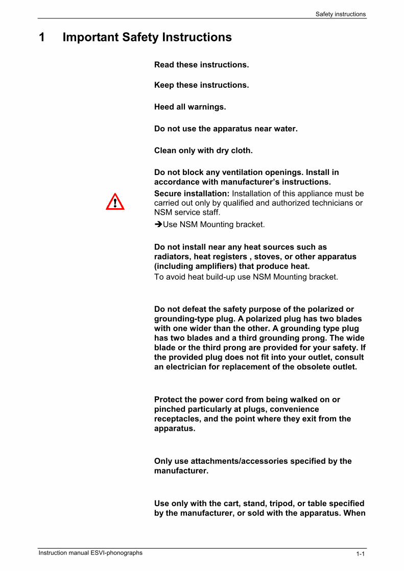
Do not block any ventilation openings. Install inaccordance with manufacturer’s instructions.Secure installation: Installation of this appliance must becarried out only by qualified and authorized technicians orNSM service staff.Use NSM Mounting bracket.
Do not install near any heat sources such asradiators, heat registers , stoves, or other apparatus(including amplifiers) that produce heat.To avoid heat build-up use NSM Mounting bracket.
Do not defeat the safety purpose of the polarized orgrounding-type plug. A polarized plug has two bladeswith one wider than the other. A grounding type plughas two blades and a third grounding prong. The wideblade or the third prong are provided for your safety. Ifthe provided plug does not fit into your outlet, consultan electrician for replacement of the obsolete outlet.
Protect the power cord from being walked on orpinched particularly at plugs, conveniencereceptacles, and the point where they exit from theapparatus.
Only use attachments/accessories specified by themanufacturer.
Use only with the cart, stand, tripod, or table specifiedby the manufacturer, or sold with the apparatus. When

Safety instructions
Instruction manual ESVI-phonographs1-2
a cart is used, use caution when moving the cart/apparatus combination to avoid injury from tip-over.
Unplug this apparatus during lightning storms orwhen unused for long periods of time.
Repair : Refer all servicing to qualified service personnel.Servicing is required when the apparatus has beendamaged in any way, such as power-supply cord orplug is damaged, liquid has been spilled or objectshave fallen into the apparatus, the apparatus hasbeen exposed to rain or moisture, does not operatenormally, or has been dropped.Repair must be carried out only by the NSM servicestaff, or by qualified and authorized service staff.
Warning: To reduce risk of fire or shock hazard, do not exposethis appliance to rain or moisture.
Intended use The phonograph is exclusively determined to playaudio CDs according to the red book standard.Any other usage apart from this is regarded as notintended.The technology of the NSM phonograph corresponds tothe state of the art and is very reliable when operating.Improper use of the phonograph may cause residualrisks if it is operated or used by non-authorizedpersons.Any person who is engaged to operate thephonograph has to read and to understand thisinstruction manual, especially these safetyinstructions.
Residual risks In this manual residual risks are marked as follows:
Warning: Disregarding the safety messages following “Warning“ cancause material damage (damage of parts).
Caution: Disregarding the safety messages following “Caution“ cancause personal damage.

Safety instructions
Instruction manual ESVI-phonographs 1-3
Ban of arbitrary reversions and changesThe phonograph must not be changed in construction orconcerning safety regulations.Any change will lead to the exclusion of liability of NSMconcerning the resulting damages. Especially defectiveparts must be replaced only by original spare parts ofNSM.
Caution: Disassembling parts and changing of any adjustments, apartfrom those specified within this manual, may result inexposure to hazardous laser radiation.
This product is a Laser Class 1 device. Disk access iscarried out by using a laser beam. The laser doesn'trepresent any risk for the user.
This product complies with the DHHS Rules 21CFRchapter 1, subchapter J, applicable at the date ofmanufacturing. Accession number: 9520184
Explanation of Graphical Symbols
This symbol indicates that a dangerous voltage constituting a risk of electric shock is present within this unit
This symbol indicates that there are important operating and maintenance instruction in the literature accompanying this unit
CLASS 1LASER PRODUCT
According to IEC 825
Safety instructions
Instruction manual ESVI-phonographs1-4
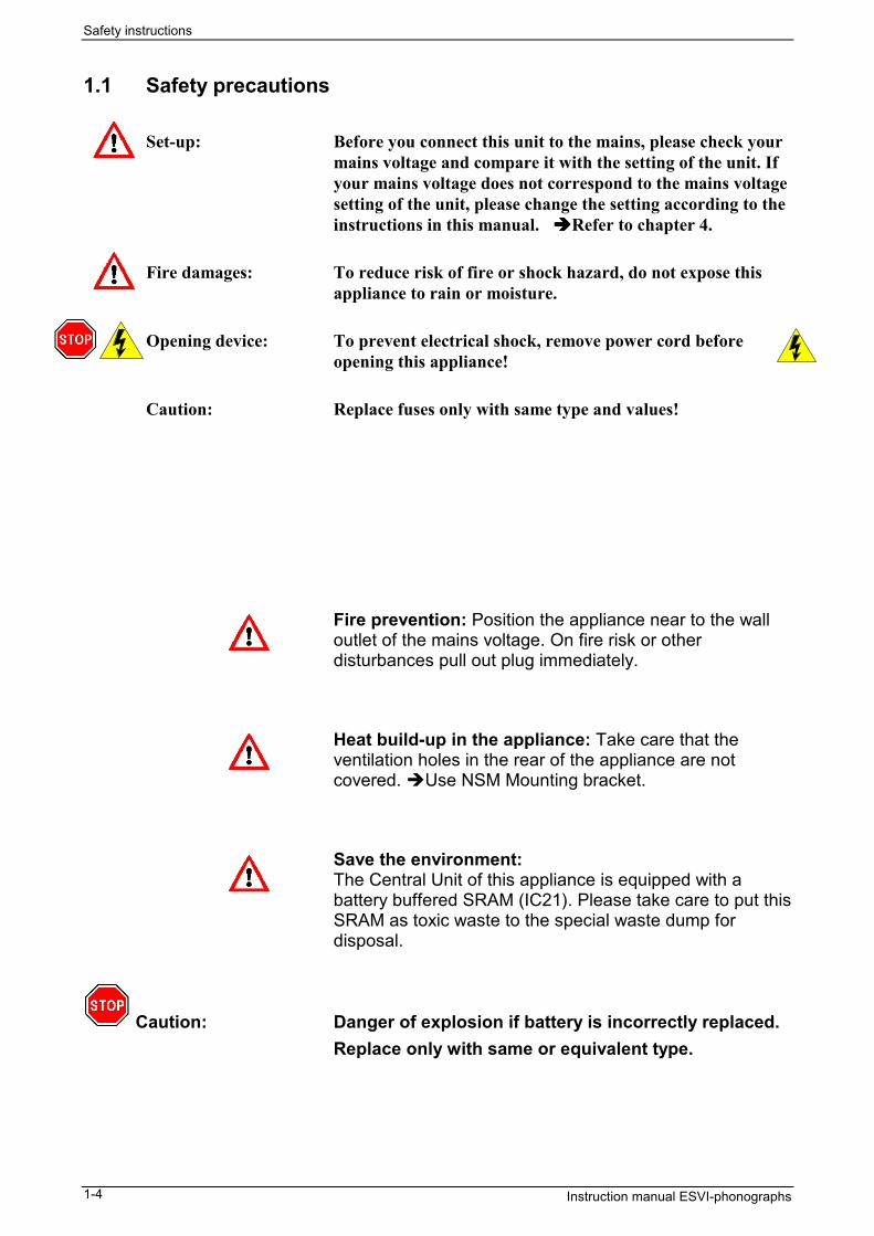
1.1 Safety precautions
Set-up: Before you connect this unit to the mains, please check yourmains voltage and compare it with the setting of the unit. Ifyour mains voltage does not correspond to the mains voltagesetting of the unit, please change the setting according to theinstructions in this manual. Refer to chapter 4.
Fire damages: To reduce risk of fire or shock hazard, do not expose thisappliance to rain or moisture.
Opening device: To prevent electrical shock, remove power cord beforeopening this appliance!
Caution: Replace fuses only with same type and values!
Fire prevention: Position the appliance near to the walloutlet of the mains voltage. On fire risk or otherdisturbances pull out plug immediately.
Heat build-up in the appliance: Take care that theventilation holes in the rear of the appliance are notcovered. Use NSM Mounting bracket.
Save the environment:The Central Unit of this appliance is equipped with abattery buffered SRAM (IC21). Please take care to put thisSRAM as toxic waste to the special waste dump fordisposal.
Caution: Danger of explosion if battery is incorrectly replaced.Replace only with same or equivalent type.

General survey of the unit
Instruction manual ESVI-phonographs 2-1
2 General survey of the unitThis phonograph is equipped with a CD changer MBC-PRO capable of storing up to 50 CDs in each magazine.
The magazine can be exchanged without much difficulty.The change of CDs is comfortably made with CD-trayinside the magazine.The basic functions are controlled manually via thekeyboard and the LCD-display in the operators panel.
2.1 Survey of front side1 = Front door2 = Title display unit3 = Coin insert, Coin return knob4 = Bill insert (option)5 = Coin return cup6 = CD changer MBC-PRO7 = Rocker button for moving title cards8 = Operators keyboard9 = Operators display10 = Lock11 = Power-on switch
2.2 Keyboard of the phonographThe phonograph is equipped with a 2 x 8 keyboard. Withthe keyboard you may enter pre-operational commands orcommands and data while operating the phonograph.The functions of the keys are:1 to 0 = numeric input, e.g. title selectionHit = to show hitparade = to move cursor on display/ to swap displaypages in service mode = changing display mode during “Service operation”C = to cancel input
Hit
C
41 532
96 087
1
2
3456789
10

General survey of the unit
Instruction manual ESVI-phonographs2-2
2.3 Display of the phonograph
The LCD-display will give you information about the actualstatus of the phonograph.The display is separated into three sections:
first line = information line
middle area = message window
bottom line = Command line / “Help messages”
It is also possible to program customer specificinformation to be displayed on the LCD, refer to theattached programming manual.
Note: The messages shown on the display are dependingon the functional state of the phonograph. They willhave different meaning during “Service mode”.

General survey of the unit
Instruction manual ESVI-phonographs 2-3
2.4 Survey of the inner componentsInside the phonograph you will additionally locatethe following:12 = CD changer MBC III-Pro13 = Title display unit14 = Bill acceptor (option)15 = Coin acceptor16 = Power supply unit17 = Amplifier channels C1 and C2 (module A) optional amplifier C3 and C4 (module B)18 = Central unit ESVI board19 = Interface board (I/O-panel)20 = Service switch, pull to enter service mode21 = Cash box22 = Type plate
2.4.1 Survey of the interface boardThe interface board offers all necessary terminals for♦ Loudspeakers output♦ Auxiliary Audio signals (input and output)♦ Microphone input♦ Selector wall box interface♦ DATA I/O:
• RS232 device• reserved for future use (prepared RS485)• Bacta interface• IR interface
12 13 14 15
16 17 18 19 20 21 22
Auxiliary Audio I/OSpeakers+ 1(L) - - 2(R) +
+ 3(L) - - 4(R) +
A
B
BACTA
Data I/O
RS232
IRMicIn L
In R
Out 1(L)
Out 2(R)
Out 3(L)
Out 4(R)

General survey of the unit
Instruction manual ESVI-phonographs2-4
This page left blank intentionally.

Operating
Instruction manual ESVI-phonographs 3-1
3 OperatingThe phonograph is ready to operate using factory defaultsettings.Additionally you may program the phonograph for yourpersonnel requirements or for the site requirements of thelocation the phonograph is to be operated. Therefore seethe additional available manual “Service program ESVItechnology”.This chapter will describe the basic functionality of thephonograph.
3.1 Power-on
Action Display / statusPower-on: Turn the power-on
switch to position“on”
The phonograph displays typeand date of the firmware forsome seconds.
NSM M.U.S.I.C.Jukebox ES6 TechnologySoftware version 1.0
Starting up . . .
Afterwards several messagesappear on the operators display.
Insert coins toearn credits.
If enough credits are registeredthe phonograph offers thepossibility to select titles.
Credits:10
Press key to select t i t le
The phonograph is ready.
NSM M.U.S.I.C.
Operating
Instruction manual ESVI-phonographs3-2
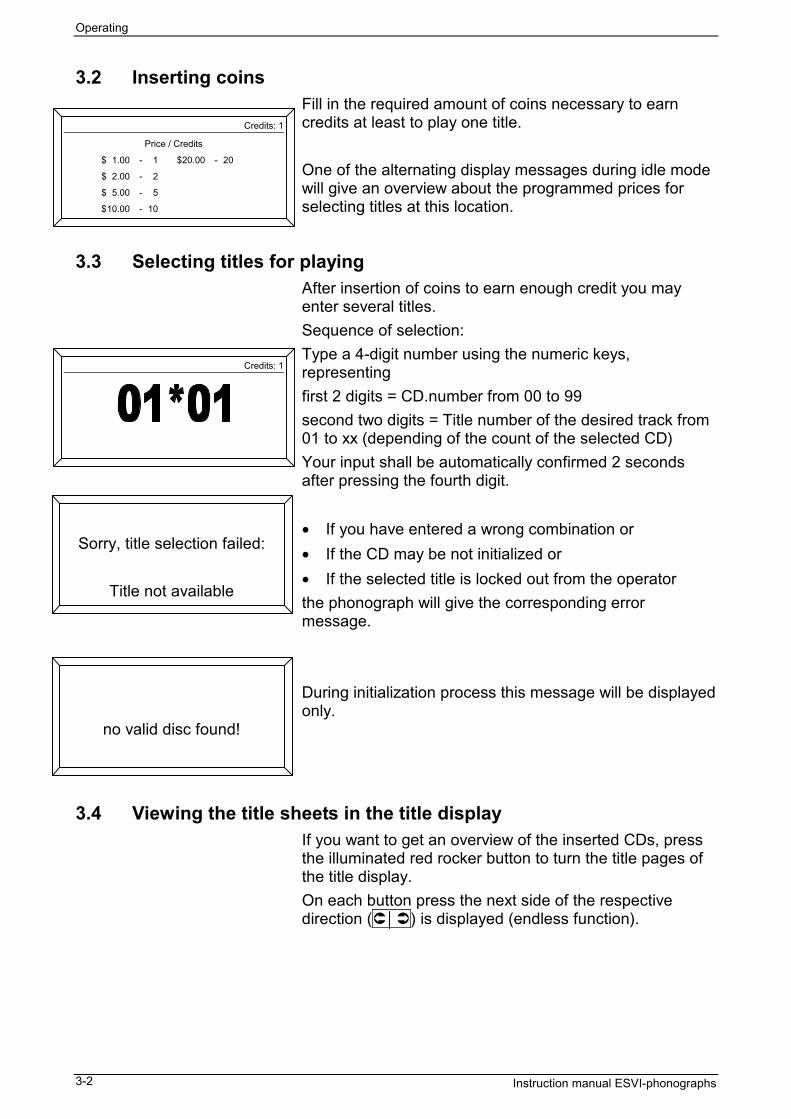
3.2 Inserting coinsFill in the required amount of coins necessary to earncredits at least to play one title.
One of the alternating display messages during idle modewill give an overview about the programmed prices forselecting titles at this location.
3.3 Selecting titles for playingAfter insertion of coins to earn enough credit you mayenter several titles.Sequence of selection:Type a 4-digit number using the numeric keys,representingfirst 2 digits = CD.number from 00 to 99second two digits = Title number of the desired track from01 to xx (depending of the count of the selected CD)Your input shall be automatically confirmed 2 secondsafter pressing the fourth digit.
• If you have entered a wrong combination or• If the CD may be not initialized or• If the selected title is locked out from the operatorthe phonograph will give the corresponding errormessage.
During initialization process this message will be displayedonly.
3.4 Viewing the title sheets in the title displayIf you want to get an overview of the inserted CDs, pressthe illuminated red rocker button to turn the title pages ofthe title display.On each button press the next side of the respectivedirection ( ) is displayed (endless function).
no valid disc found!
Sorry, title selection failed:
Title not available
Credits: 1
Price / Credits
$ 1.00 - 1 $20.00 - 20
$ 2.00 - 2
$ 5.00 - 5
$10.00 - 10
Credits: 1

Operating
Instruction manual ESVI-phonographs 3-3
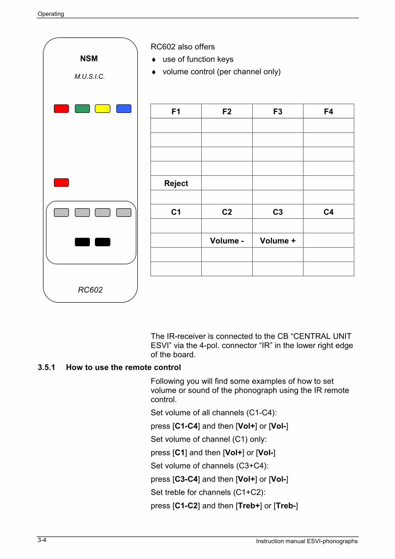
3.5 IR Remote control RC601 and RC 602Two infra-red remote controls are available to control the phonograph:RC601 giving full functionality and controlRC602 with reduced functionality limited to basic functions.
The RC601 offers following possibilities♦ selecting titles♦ setting volume and sound♦ function keys F1 to F4 programmable via service
program (i.e. background mode, free credits, reject)
The functions of the keys are:
F1 F2 F3 F4
1ABC 2DEF 3GHI
4JKL 5MNO 6PQR
7STU 8VWX 9YZ
C 0Sym Hit
Reject VIP
C1 C2 C3 C4
C1/2 C3/4 C1-4 Mic
Volume - Volume +
Treble - Treble + Bass - Bass +
Surr SRS Mute NormF1 to F4 = user defined function keys (free credit, background, etc.)
1 to 0 = numeric input keysC = Cancel/Clear input* = Change display mode during “Service mode”Hit = Show the HitparadeVIP = select a VIP titleMIC = select microphone channelSurr = activate surround soundSRS = activate SRS soundC1 to C4 = select audio channels
NSM
M.U.S.I.C.
RC601
Operating
Instruction manual ESVI-phonographs3-4
RC602 also offers♦ use of function keys♦ volume control (per channel only)
F1 F2 F3 F4
Reject
C1 C2 C3 C4
Volume - Volume +
The IR-receiver is connected to the CB “CENTRAL UNITESVI” via the 4-pol. connector “IR” in the lower right edgeof the board.
3.5.1 How to use the remote controlFollowing you will find some examples of how to setvolume or sound of the phonograph using the IR remotecontrol.Set volume of all channels (C1-C4):press [C1-C4] and then [Vol+] or [Vol-]Set volume of channel (C1) only:press [C1] and then [Vol+] or [Vol-]Set volume of channels (C3+C4):press [C3-C4] and then [Vol+] or [Vol-]Set treble for channels (C1+C2):press [C1-C2] and then [Treb+] or [Treb-]
NSM
M.U.S.I.C.
RC602

Operating
Instruction manual ESVI-phonographs 3-5
Set bass for channels (C3+C4):press [C3-C4] and then [Bass+] or [Bass -]Set microphone volume for channel (C3):press [C3] [Mic] and then [Vol+] or [Vol-]Set treble for this microphone channel:press [C3] [Mic] and then [Treb+] or [Treb-]
3.5.2 Mounting remarks for IR receiverRegard the following mounting instruction for bestfunction results of the IR receiver.
The IR receiver can be mounted either to the top of thephonograph or to a wall near the phonograph.Regard the length of the connection cable.
Place the housing of the IR receiver (1) in that way, thatthe internally mounted IR-module (2) will meet the IRbeam of the IR hand transmitter.
Take care to avoid that the IR beam “hits” the IR receiverfrom the side or the back (cable outlet). This will causemalfunction of the remote control.
2
1
IR beam
IR receiver wall mounted:
1
2
IR beam
IR receiver mounted ontop of the box:
Operating
Instruction manual ESVI-phonographs3-6
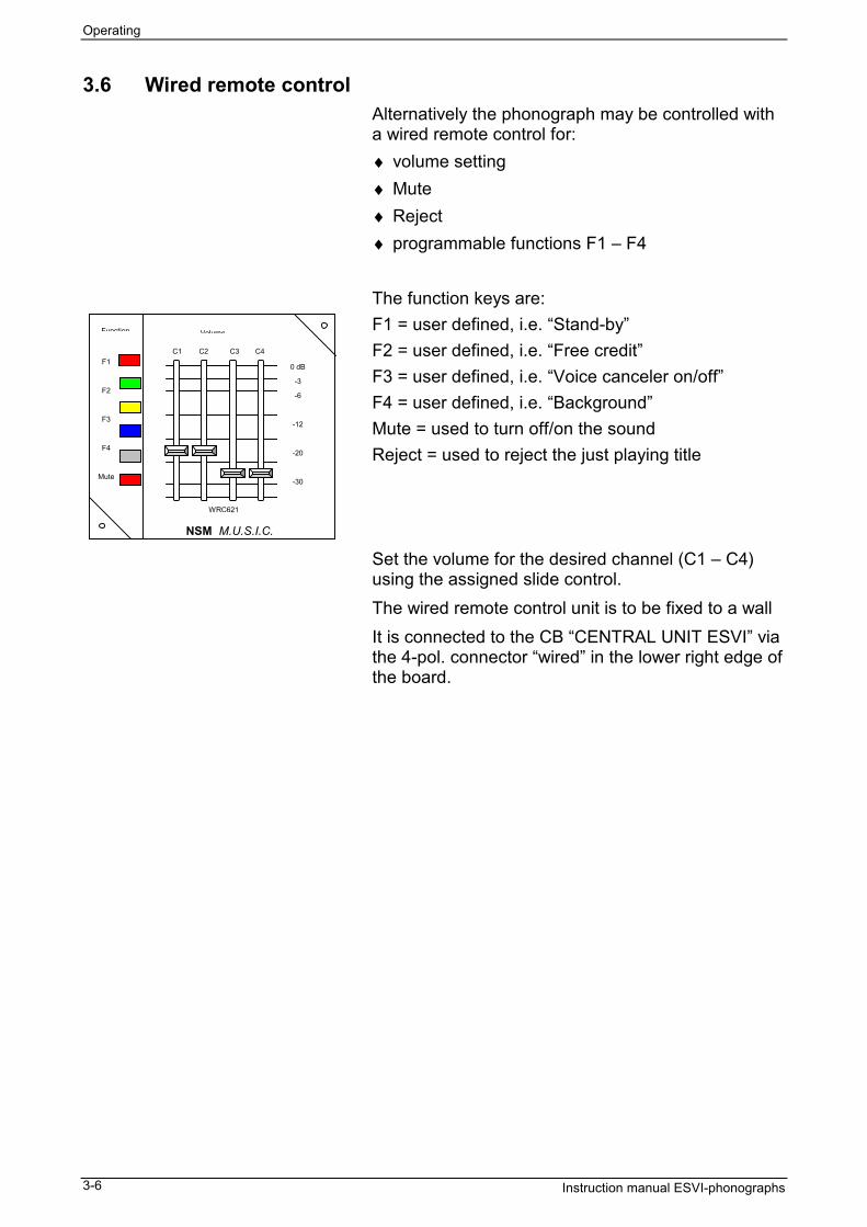
3.6 Wired remote controlAlternatively the phonograph may be controlled witha wired remote control for:♦ volume setting♦ Mute♦ Reject♦ programmable functions F1 – F4
The function keys are:F1 = user defined, i.e. “Stand-by”F2 = user defined, i.e. “Free credit”F3 = user defined, i.e. “Voice canceler on/off”F4 = user defined, i.e. “Background”Mute = used to turn off/on the soundReject = used to reject the just playing title
Set the volume for the desired channel (C1 – C4)using the assigned slide control.The wired remote control unit is to be fixed to a wallIt is connected to the CB “CENTRAL UNIT ESVI” viathe 4-pol. connector “wired” in the lower right edge ofthe board.
Function Volume
WRC621
NSM M.U.S.I.C.
C1 C2 C3 C4
0 dB
-3
-6
-12
-20
-30
F1
F2
F3
F4
Mute

Set-up
Instruction manual ESVI-phonographs 4-1
4 Set-upWarning Read this set-up instructions.
In this chapter you will find all information being necessaryto set-up the phonograph correctly.
4.1 Survey of Set-upFor the set-up perform the following steps. Details to thesingle steps are explained in the following subchapters.StepWhat to do at first?Check if the delivery is complete; see below •Prepare siteMount the mounting bracket; see page 4-2 •Mount unit to its final place; see page 4-5 •Open the appliance; see page 4-5 •Make external connections; see page 4-6 •Prepare the applianceRemove transportation fixtures; see page 4-5 •Load CDs; see page 4-7 •Feed title display; see page 4-8 •Check all wiring/components; see page 4-8 •Power–on; see page 4-8 •
4.2 What to do at first?4.2.1 Check if the delivery is complete
Warning: Depending on the heavy weight of the appliance werecommend that two persons should work together tounpack the phonograph.Unpack the unit and check if the delivery is complete:1 phonograph1 mains (power) cord1 pair of keys to open the front door of the phonograph1 instruction manual
If any parts are missing inform your supplier.Please fill in the warranty card and send it back toNSM MUSIC GmbH - Germany.
Note: Store the shipping carton and the packaging materialfor a possible later transport. Thus you can transportyour unit safely.

Set-up
Instruction manual ESVI-phonographs4-2
4.3 Prepare siteIn order to guarantee a correct functioning of the coinmechanism mount the appliance horizontally and verticallyexactly.
4.3.1 Use NSM Mounting bracketTherefore, we recommend usage of the practical NSMmounting bracket (part-no. 040 739).
Take care to mount the bracket untwisted since the rear ofthe cabinet otherwise can be twisted too.
When choosing the fastening material, take into accountthe weight of the appliance. We recommend nylon dowelpins in sufficient quantities.
The screws should be at least 6 mm (1/4”) in diameter!
4.3.2 Example of mounting the NSM mounting bracket using nylon dowel-pinsFirst a few tips:The maximum bearing capacity of nylon dowel pins mayonly be achieved with the greatest possible screwdiameters and with screws exceeding the dowel point bythe screw diameter again.Please ensure that with fixings in hollow brick and hollowblocks the expansion zone of the dowel is completelyanchored in at least one stone web.Calculation of minimum screw length:
1xd (d= nominal diameter of screw)+ dowel length+ thickness of plaster and / or insulating material+ thickness of mounting bracket 3 mm= minimum length of screws to be used.
Proposed length 60mm (2.5”)
4.3.3 Drill hole geometryThe exact drill hole geometry dictates the load-bearingcapacity of a dowel pin.Therefore always drill at right-angles and do not changedirection during drilling. This has especially to be observedin the case of soft materials.
4.3.4 Drill processThe following drilling methods are possible depending onthe type of drilling machine:• Rotary - without impact• Impact drill-many impacts with a low amount of impact
energy. Fast rotation
observe the screw diameter
Important:min. 1x the screw diameter
Set-up
Instruction manual ESVI-phonographs 4-3
• Hammer drill - few impacts with a high amount ofimpact energy. Slow rotation
The material determines the drill process:• Solid materials of dense structure: impact and hammer
drilling• Materials of low strength and aerated concrete: only
rotary; so that the holes don’t become too big.• Hollow brick: only rotary; so that webs don’t break out.Never forget to remove the dust from the drill hole afterdrilling. Only then dowel pins performs safety fixing.
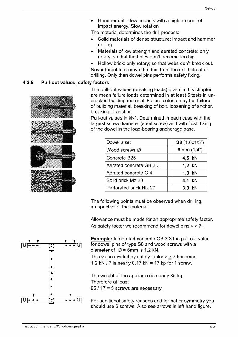
4.3.5 Pull-out values, safety factorsThe pull-out values (breaking loads) given in this chapterare mean failure loads determined in at least 5 tests in un-cracked building material. Failure criteria may be: failureof building material, breaking of bolt, loosening of anchor,breaking of anchor.Pull-out values in kN*. Determined in each case with thelargest screw diameter (steel screw) and with flush fixingof the dowel in the load-bearing anchorage base.
Dowel size: S8 (1.6x1/3”)Wood screws ∅ 6 mm (1/4”)Concrete B25 4,5 kNAerated concrete GB 3,3 1,2 kNAerated concrete G 4 1,3 kNSolid brick Mz 20 4,1 kNPerforated brick Hlz 20 3,0 kN
The following points must be observed when drilling,irrespective of the material:
Allowance must be made for an appropriate safety factor.As safety factor we recommend for dowel pins ν > 7.
Example: In aerated concrete GB 3,3 the pull-out valuefor dowel pins of type S8 and wood screws with adiameter of ∅ = 6mm is 1,2 kN.This value divided by safety factor ν > 7 becomes1,2 kN / 7 is nearly 0,17 kN = 17 kp for 1 screw.
The weight of the appliance is nearly 85 kg.Therefore at least85 / 17 = 5 screws are necessary.
For additional safety reasons and for better symmetry youshould use 6 screws. Also see arrows in left hand figure.
Set-up
Instruction manual ESVI-phonographs4-4
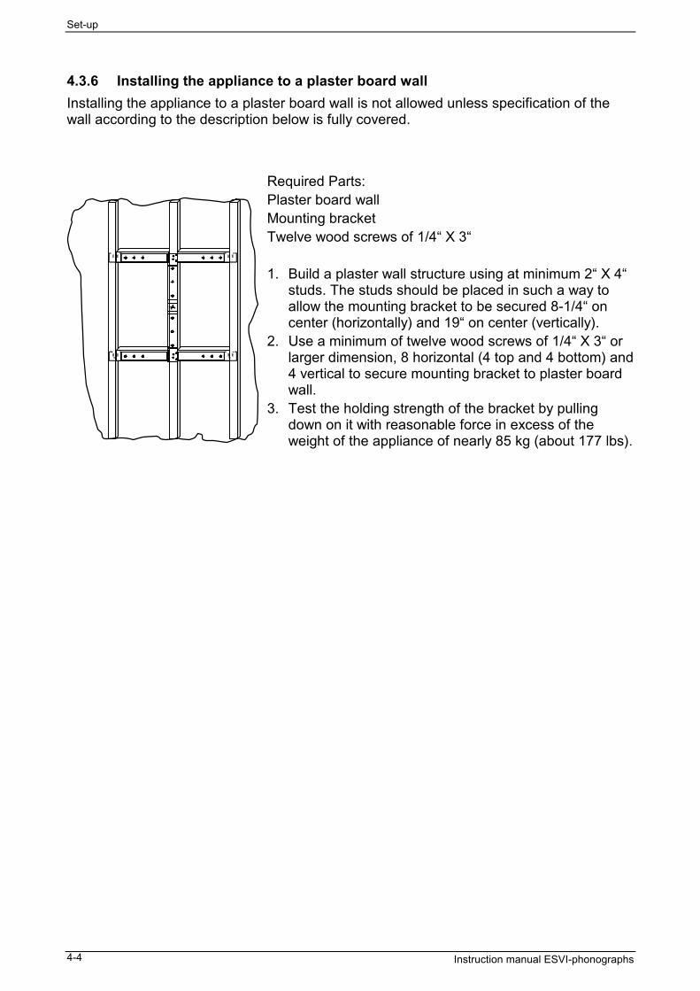
4.3.6 Installing the appliance to a plaster board wallInstalling the appliance to a plaster board wall is not allowed unless specification of thewall according to the description below is fully covered.
Required Parts:Plaster board wallMounting bracketTwelve wood screws of 1/4“ X 3“
1. Build a plaster wall structure using at minimum 2“ X 4“studs. The studs should be placed in such a way toallow the mounting bracket to be secured 8-1/4“ oncenter (horizontally) and 19“ on center (vertically).
2. Use a minimum of twelve wood screws of 1/4“ X 3“ orlarger dimension, 8 horizontal (4 top and 4 bottom) and4 vertical to secure mounting bracket to plaster boardwall.
3. Test the holding strength of the bracket by pullingdown on it with reasonable force in excess of theweight of the appliance of nearly 85 kg (about 177 lbs).

Set-up
Instruction manual ESVI-phonographs 4-5
4.4 Prepare the appliance4.4.1 Observe when fixing the appliance to the wall
Note: Plug in connection cables before hanging up theappliance.To secure the appliance to the mounting bracket, aholding screw with sleeve M 10x20 (part no. 176 999) is tobe used (->accessory bag).
Caution Secure mounting of the appliance is very important sincebesides the danger of severely damaging the appliance, theoperator is responsible for all damages caused by anincorrectly mounted appliance.When fixing the appliance to the wall, make sure the aircirculation is not hindered in its function.When using the mounting bracket, there is normallyenough distance between cabinet and wall for aircirculation. Plush wall hangings decrease this distance; inthat case the bracket has to be fastened to a flat board.Do not mount appliance above heaters!Keep ventilation holes free.
Now you can mount the phonograph onto the mountingbracket. Regard your wellness.The phonograph is heavy weighting.Just do it only when you have a colleague or partner tohelp you.After you have mounted the appliance to the wall or thestand you have to prepare it for operation.
4.4.2 Open the applianceInsert the delivered key into the lock at the right hand side.Turn it clockwise to open the front door of the unit.
4.4.3 Transportation security devicesBefore operating the appliance all security devices forsafety and protection during transport have to beremoved.
Warning The unit must be switched on only when the transportationfixtures have been removed.
So first remove the transportation fixtures after hanging itonto the wall mounting bracket.Prior to any further transportation the security devices forsafety and protection during transport have to be re-inserted.
Note: Store the transportation fixtures in a safe place. Re-insert them always into the unit before anytransportation.

Set-up
Instruction manual ESVI-phonographs4-6
Avoid static discharge to the appliance. Electro StaticDischarge (ESD) may destroy the opto-electronics andother ESD sensitive parts within the appliance.
Caution: Before connecting the power cord to the wall outlet:1. Check the setting of the line voltage and compare it with the setting of the unit.2. Remove all transportation fixtures. Otherwise the appliance might be damaged.
4.4.4 External connectionsConnection of loudspeakers
The appliance is equipped with a semi-digital, high-poweramplifier to connect the loudspeakers to.Regard the right polarity of the connected speaker cablesto get best sound results.
Warning: Installation of necessary wiring must be carried out only byqualified and authorized technicians.Otherwise the amplifier might be damaged.Lead the speaker cables through the outlet in the back ofthe phonograph housing phonograph through the cablechannel in the bottom to the inside.Two wires for each channel have to be connected to theconnecting taps on the interface board.
Caution: Power-off the appliance before connecting loudspeakers.Do not touch loudspeaker connectors. Risk of shock hazardthrough high voltage. Abuse, shortening or interconnectingof cabling may cause serious damage to amplifier!
Warning: CLASS 2 wiring may be used!There is a total power output of 250W RMS on eachchannel.
Remote control cablingTo simplify the operating of the phonograph you shoulduse a remote control unit (infra-red or wired remotecontrol).Lead the connecting cable also through the outlet in theback of the phonograph through the cable channel in thebottom into the inside. Then connect it to the desired plugconnector “IR” / ”WIRED”, located on the CENTRAL UNIT.
Mains cablingAfter checking all cabling is done well insert the mainsplug into the mains connector on the rear side of thephonograph.
Set-up
Instruction manual ESVI-phonographs 4-7
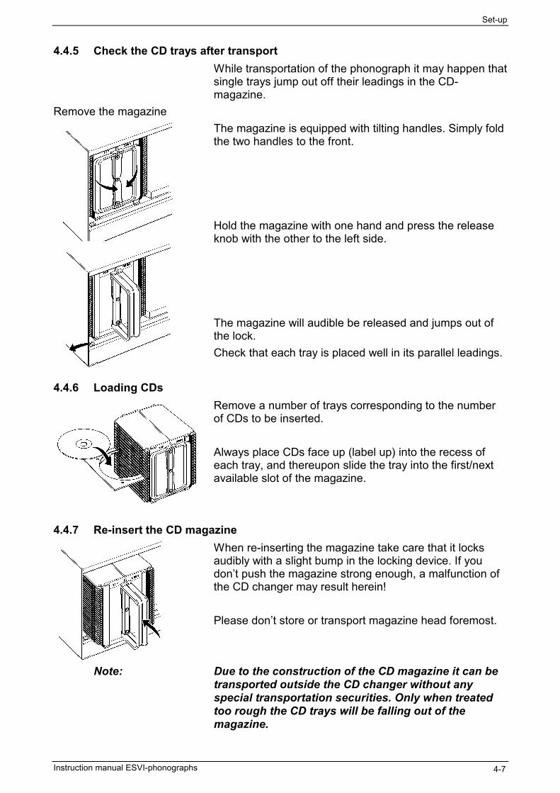
4.4.5 Check the CD trays after transportWhile transportation of the phonograph it may happen thatsingle trays jump out off their leadings in the CD-magazine.
Remove the magazineThe magazine is equipped with tilting handles. Simply foldthe two handles to the front.
Hold the magazine with one hand and press the releaseknob with the other to the left side.
The magazine will audible be released and jumps out ofthe lock.Check that each tray is placed well in its parallel leadings.
4.4.6 Loading CDsRemove a number of trays corresponding to the numberof CDs to be inserted.
Always place CDs face up (label up) into the recess ofeach tray, and thereupon slide the tray into the first/nextavailable slot of the magazine.
4.4.7 Re-insert the CD magazineWhen re-inserting the magazine take care that it locksaudibly with a slight bump in the locking device. If youdon’t push the magazine strong enough, a malfunction ofthe CD changer may result herein!
Please don’t store or transport magazine head foremost.
Note: Due to the construction of the CD magazine it can betransported outside the CD changer without anyspecial transportation securities. Only when treatedtoo rough the CD trays will be falling out of themagazine.

Set-up
Instruction manual ESVI-phonographs4-8
4.4.8 Loading title strips to the title displayThe title display consists of 14 carriers and is designed toshow 104 title strips (13 times 8).
Loading title strips and CD coversIf you want to insert or remove title strips and /or CDcovers you first have to open the phonograph, if notalready done.
Insert the title strips into the fields of the title display• You have to be careful while inserting the CD covers
and title strips into the title holders. Be sure CD coversand title strips are inserted under all the black plastictabs. This will insure that they don’t fall out. The titledisplay will always show eight covers of inserted CDs.
• You have to press the rocker button, placed in theoperator console of the phonograph, if you want tomove the title holders to the next position.
• You have to take care to insert only the correspondingnumber of title strips and CD covers.
4.4.9 Check all wiring and componentsAfter finishing the installation of wiring, the insertion ofCDs and title sheets you should check once more• if all wiring is correctly made• if all components are placed in a correct mannerAfterwards plug in the mains plug into the correspondingwall outlet.
4.4.10 Power-on the applianceThe power-on switch is located right hand at the bottomside of the appliance. To turn on the power just switch it toist opposite position.If all installation was ok the lights should go bright and theinitialisation routine should be displayed on the operatorsdisplay.After a moment the appliance is ready.
4.4.11 Initialize the CDs to the central unit ESVIYou have two possibilities to initialize the inserted CDs.After inserting• if you only have inserted one or a few of CDs just play
the first track of each CD.• if you have inserted a lot of CDs it is easier to call up
the service program and start the initialization routineof the phonograph.
See manual “Service program ES VI technology”.
Repair Failures
Instruction manual ESVI-phonographs 5-1
5 Disturbances5.1 Avoiding disturbancesReason of disturbances Errors during the loading process of the magazine or a
wrong manual insert of the CDs mostly result inmechanical disturbances.To avoid disturbances please adhere to the followingrecommendations:
Use CD-tray Put CDs only into the trays label-up.Inside the CD changer CDs can only be transported if theyare placed on trays.
Load CD magazine completelyLoad the CD magazine completely with trays even if youdo not fill in all trays with CDs.Operate the phonograph only with all 50 trays installed.
By factory setting the magazine is equipped with all trays.Do not remove trays.
Insert CD magazine correctlyWhen inserting a CD magazine pay attention to the TOPposition.The magazine must snap in clearly audible.An incorrectly inserted CD magazine will lead tomechanical disturbances.

Repair Failures
Instruction manual ESVI-phonographs5-2
5.2 Reports on the displayThe following table contains some display reports of thephonograph.The given information is intended to help you to removedisturbances.
Report Reason AccomodationTitle not available The
correspondingCD is notavailable orunknown
Insert CD;initialize CD#
no valid disc found terminateinitializationroutine

Repair Failures
Instruction manual ESVI-phonographs 5-3
5.3 Replacing line fusesCaution Always unplug the power cord before exchanging line fuses.
Use only fuses as specified below.
The two line fuses have the following values:• T 5 AL for line voltage 230 V• T 8 A for line voltage 120 V
The line fuses are located in the bottom part of thephonograph cabinet. To get access to the fuses• Power-off the phonograph and unplug the power cord.• Open the front door.• Remove 2 screw and fold the operator panel towards
you.• Nearly in the middle of the bottom part you will see the
two fuse holders.• Open the fuse caps and replace the fuses.• Re-build the original state of the phonograph and
power-on again.
Warning Replace fuses only with same type and value! Otherwise thephonograph may be damaged in hole.
5.4 Replacing the secondary fusesThe secondary fuses are placed on the two printed boardsof the power supply unit.The secondary fuses have the following values:• T 6,3 AL for 60 VA
• T 6,3 AL for 60 VB
• T 1 AL for 30 V• T 3,15 AL for 15 V• T 3,15 AL for 12 V• T 3,15 AL for 5 V
Warning Replace fuses only with same type and value! Otherwise thephonograph may be damaged in hole.
Repair Failures
Instruction manual ESVI-phonographs5-4
This page left blank intentionally.

Spare parts catalog
Instruction manual ESVI-phonographs 6-1
6 Spare parts catalogThe following spare parts and options are available for theESVI-phonograph:
Spare parts catalog
Instruction manual ESVI-phonographs6-2
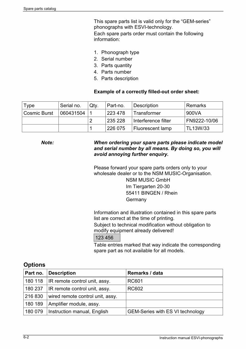
This spare parts list is valid only for the “GEM-series”phonographs with ESVI-technology.Each spare parts order must contain the followinginformation:
1. Phonograph type2. Serial number3. Parts quantity4. Parts number5. Parts description
Example of a correctly filled-out order sheet:
Type Serial no. Qty. Part-no. Description RemarksCosmic Burst 060431504 1 223 478 Transformer 900VA
2 235 228 Interference filter FN9222-10/061 226 075 Fluorescent lamp TL13W/33
Note: When ordering your spare parts please indicate modeland serial number by all means. By doing so, you willavoid annoying further enquiry.
Please forward your spare parts orders only to yourwholesale dealer or to the NSM MUSIC-Organisation.
NSM MUSIC GmbHIm Tiergarten 20-3055411 BINGEN / RheinGermany
Information and illustration contained in this spare partslist are correct at the time of printing.Subject to technical modification without obligation tomodify equipment already delivered!123 456
Table entries marked that way indicate the correspondingspare part as not available for all models.
OptionsPart no. Description Remarks / data180 118 IR remote control unit, assy. RC601180 237 IR remote control unit, assy. RC602216 830 wired remote control unit, assy.180 189 Amplifier module, assy.180 079 Instruction manual, English GEM-Series with ES VI technology
Spare parts catalog
Instruction manual ESVI-phonographs 6-3
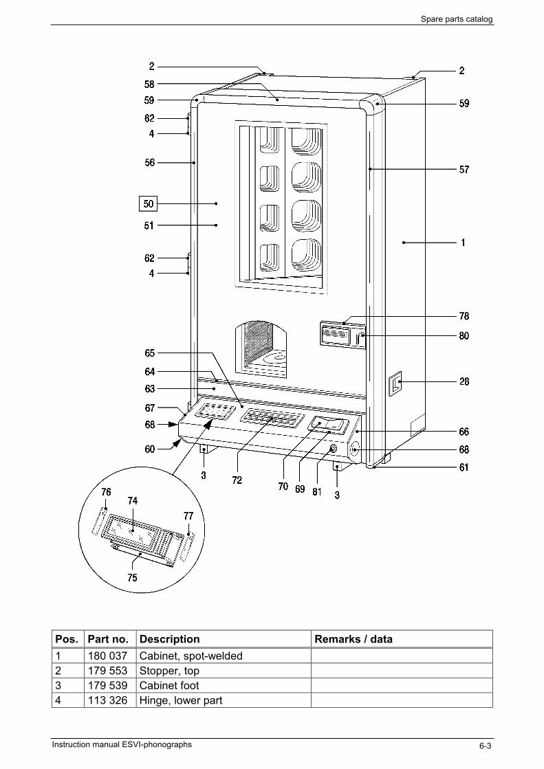
Pos. Part no. Description Remarks / data1 180 037 Cabinet, spot-welded2 179 553 Stopper, top3 179 539 Cabinet foot4 113 326 Hinge, lower part
Spare parts catalog
Instruction manual ESVI-phonographs6-4
Option
Option
Spare parts catalog
Instruction manual ESVI-phonographs 6-5
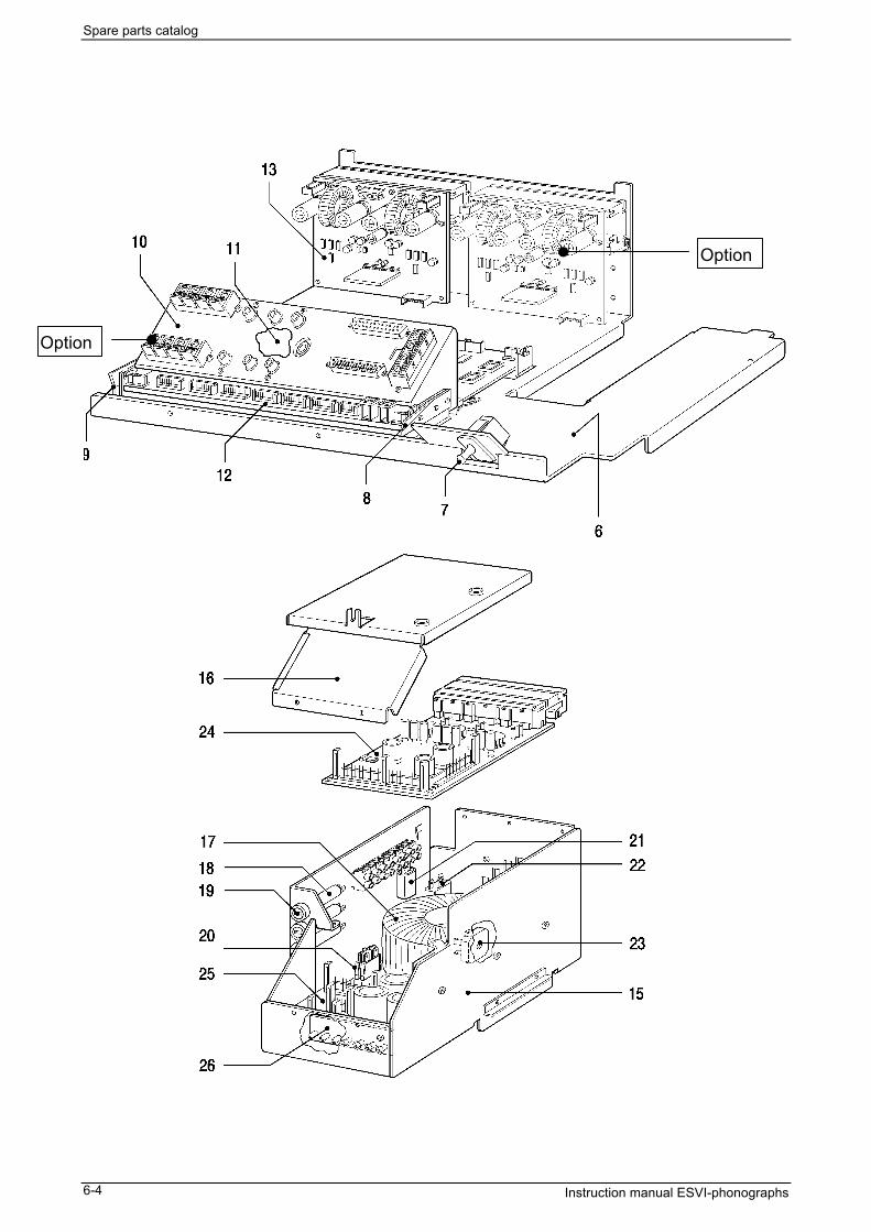
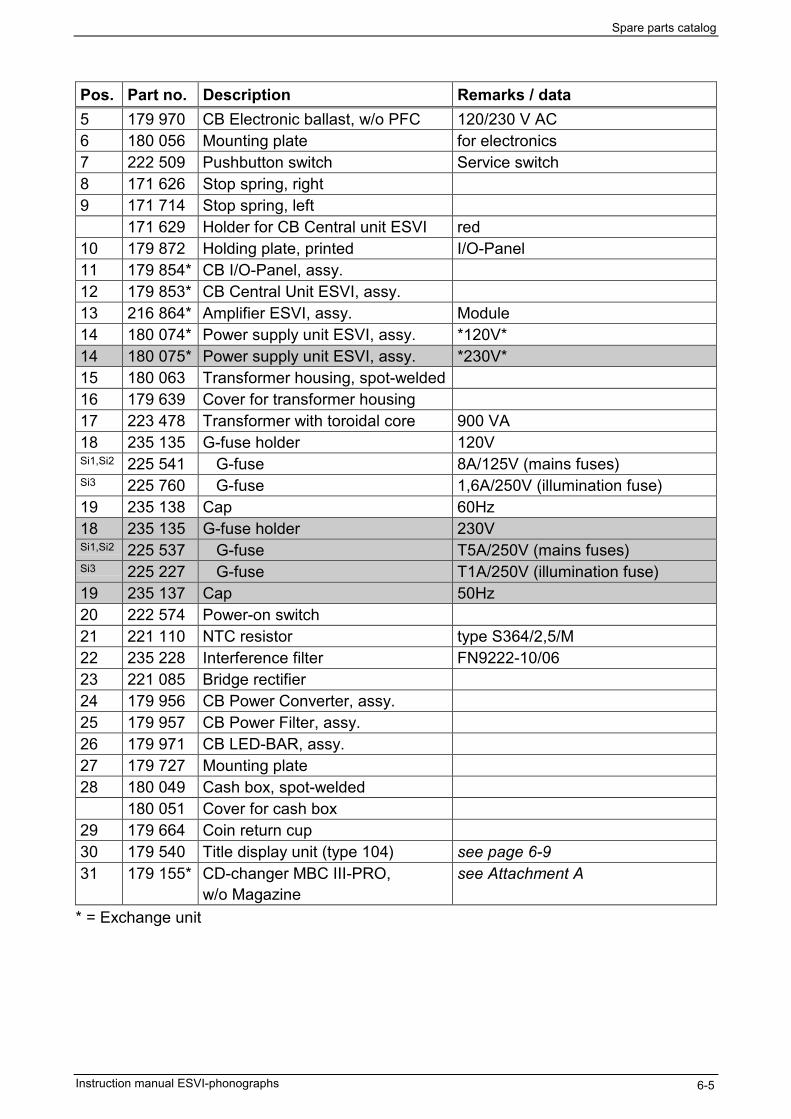
Pos. Part no. Description Remarks / data5 179 970 CB Electronic ballast, w/o PFC 120/230 V AC6 180 056 Mounting plate for electronics7 222 509 Pushbutton switch Service switch8 171 626 Stop spring, right9 171 714 Stop spring, left
171 629 Holder for CB Central unit ESVI red10 179 872 Holding plate, printed I/O-Panel11 179 854* CB I/O-Panel, assy.12 179 853* CB Central Unit ESVI, assy.13 216 864* Amplifier ESVI, assy. Module14 180 074* Power supply unit ESVI, assy. *120V*14 180 075* Power supply unit ESVI, assy. *230V*15 180 063 Transformer housing, spot-welded16 179 639 Cover for transformer housing17 223 478 Transformer with toroidal core 900 VA18 235 135 G-fuse holder 120VSi1,Si2 225 541 G-fuse 8A/125V (mains fuses)Si3 225 760 G-fuse 1,6A/250V (illumination fuse)19 235 138 Cap 60Hz18 235 135 G-fuse holder 230VSi1,Si2 225 537 G-fuse T5A/250V (mains fuses)Si3 225 227 G-fuse T1A/250V (illumination fuse)19 235 137 Cap 50Hz20 222 574 Power-on switch21 221 110 NTC resistor type S364/2,5/M22 235 228 Interference filter FN9222-10/0623 221 085 Bridge rectifier24 179 956 CB Power Converter, assy.25 179 957 CB Power Filter, assy.26 179 971 CB LED-BAR, assy.27 179 727 Mounting plate28 180 049 Cash box, spot-welded
180 051 Cover for cash box29 179 664 Coin return cup30 179 540 Title display unit (type 104) see page 6-931 179 155* CD-changer MBC III-PRO,
w/o Magazinesee Attachment A
* = Exchange unit

Spare parts catalog
Instruction manual ESVI-phonographs6-6
Pos. Part no. Description Remarks / data50 180 072 Front door, complete *USA* USA version only50 180 073 Front door, complete *USE* export version51 160 168 Front glass *COSMIC BURST*
217 507 Rubber profile 2x780mm; 2x600mm

Spare parts catalog
Instruction manual ESVI-phonographs 6-7
Pos. Part no. Description Remarks / data52 179 746 Front glass holder, left53 179 737 Front glass holder, upper54 179 597 Front glass holder, right55 226 075 Fluorescent lamp white, TL13W/3356 250 564 Frame, left black57 250 565 Frame, right black58 250 566 Frame, upper black59 119 635 Edge connector black60 121 367 End connector, left black61 121 368 End connector, right black62 250 457 Hinge, upper part63 180 014 Pult plate, spot-welded64 250 529 Cross profile, bottom65 239 360 Cross profile, cover66 179 537 Pult plate cover, right67 179 538 Pult plate cover, left68 179 683 Decor plate, small69 176 574 Frame for rocker button70 175 974 Rocker button71 179 297 Cover, pre-mounted72 179 902 Keyboard, assy. 16 buttons74 180 171 Bezel and glass for display, assy.75 179 900 CB Display, assy.76 171 626 Catch spring, right77 171 714 Catch spring, left
171 629 Holder for CB Display red78 179 551 Frame *USA* for Dollar Bill Acceptor78 179 552 Frame Standard for Coin acceptor only79 180 052 Holding plate for frame80 179 197 Coin return lever
205 683 Pressure spring179 279 Washer, plastic
81 206 903 Lock *USA*82 179 593 Lever for lock81 217 814 Cylinder lock *UNI*82 180 167 Lever for lock83 179 630 Closing lever
179 631 Flange sleeve84 205 582 Tension spring85 179 627 Closing bar, riveted86 179 821 Lifting protection87 179 629 Closing hook
Spare parts catalog
Instruction manual ESVI-phonographs6-8
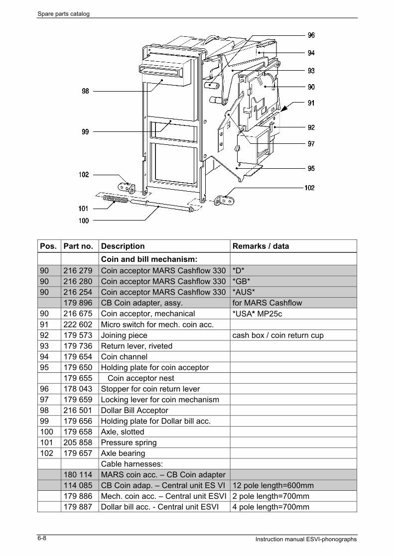
Pos. Part no. Description Remarks / dataCoin and bill mechanism:
90 216 279 Coin acceptor MARS Cashflow 330 *D*90 216 280 Coin acceptor MARS Cashflow 330 *GB*90 216 254 Coin acceptor MARS Cashflow 330 *AUS*
179 896 CB Coin adapter, assy. for MARS Cashflow90 216 675 Coin acceptor, mechanical *USA* MP25c91 222 602 Micro switch for mech. coin acc.92 179 573 Joining piece cash box / coin return cup93 179 736 Return lever, riveted94 179 654 Coin channel95 179 650 Holding plate for coin acceptor
179 655 Coin acceptor nest96 178 043 Stopper for coin return lever97 179 659 Locking lever for coin mechanism98 216 501 Dollar Bill Acceptor99 179 656 Holding plate for Dollar bill acc.100 179 658 Axle, slotted101 205 858 Pressure spring102 179 657 Axle bearing
Cable harnesses:180 114 MARS coin acc. – CB Coin adapter114 085 CB Coin adap. – Central unit ES VI 12 pole length=600mm179 886 Mech. coin acc. – Central unit ESVI 2 pole length=700mm179 887 Dollar bill acc. - Central unit ESVI 4 pole length=700mm

Spare parts catalog
Instruction manual ESVI-phonographs 6-9
Pos. Part no. Description Remarks / data179 540 Title display 104, complete
1 179 541 Cabinet, complete w/o design parts217 479 Edge protection black, 4x102mm206 414 Edge protection DX2, 2x155mm, for lower handle
2 179 792 Decor mask white3 179 688 Decor mask black4 212 967 Cover mask white5 179 225 Title holder
219 861 Adhesive sticker 00 – 996 179 542 Gear, pre-mounted
179 702 Cover plate for gear, riveted179 544 Toothed wheel, double z=69, z=15179 545 Toothed wheel z=23179 707 Motor, complete116 365 Step bearing173 432 Worm gear205 568 Tension spring
7 179 709 CB Opto, complete231 322 Opto coupler LTH-301A-N
8 179 708 CB Title display 104, complete229 157 Spacer
9 179 718 Clamping bracket10 211 785 Bar with projection11 179 549 Guiding12 179 238 Foot, long
10
3
2
8
12 4 7 6 11 12
5
2
9
14

Spare parts catalog
Instruction manual ESVI-phonographs6-10
Cable harnesses
Part no. Description Remarks / data227 433 Power cord EURO *D*/*EXP*, length=2500mm227 629 Power cord with plug *GB*, length=2500mm227 529 Power cord w/o plug *AUS*/*NZ*, length=2500mm227 528 Power cord (110-127V) *USA*, length=2500mm
179 882 Power supply unit – CB Central Unit 8 pole, length=450mm180 034 Power supply unit – Electronic ballast 6 pole, length=1100mm179 885 Power supply unit – AMP 6 pole, length=600mm179 962 CB Power Filter – CB Converter 12 pole, length=200mm
179 879 AMP – Loudspeaker connector 4 pole, length=450mm179 905 CB Central Unit –AMP 8 pole, length=340mm
179 856 CB Central Unit – I/O-Panel 18 pole, length=100mm179 857 CB Central Unit – I/O-Panel 20 pole, length=100mm179 895 CB Central Unit –Service switch 2 pole, length=250mm179 892 CB Central Unit – MBC III 15 pole, length=1200mm178 012 CB Central Unit – Title display 10 pole, length=1470mm177 478 CB Central Unit – CB Display 8 pole, length=1100mm179 888 Display – Rocker button 6 pole, length=700mm
180 035 Front door illumination

Appendix
Instruction manual ESVI-phonographs 7-1
7 Appendix7.1 Technical data
Electrical dataMains voltage 120V / 230V 50/60HzPower consumption 115W stand-by
600W play mode
each channelRMS power / load (sine wave power) 170Wrms / 8Ω
250Wrms / 4Ω
Music power (tone burst) 2 x 200W / 8Ω 4 x 175W / 8Ω2 x 300W / 4Ω 4 x 250W / 4Ω2 x 400W / 2Ω 4 x 250W / 2Ω *)
*) = limited byovercurrentprotection!
Operating conditionsAmbient temperature operating 10°C — 40°C 50°F — 104°FGradient of temperature 11°C/h 19,8°F/hRelative humidity operating 10 % - 75 % non condensing
Dimension and WeightDimension Width 650 mm ≈ 25.5”
Height 1042 mm ≈ 41”Depth 361 mm ≈ 14.2”
Weight w/o CDs nearly 85kg
InterfacesAuxiliary Interface 2 x input 4 x outputSerial interface 1 x RS232
1 x BACTA1 x Selector box
Operators panel 16 key keyboardLCD-display

Appendix
Instruction manual ESVI-phonographs7-2
7.2 Wiring diagram

Appendix
Instruction manual ESVI-phonographs 7-3
7.3 Service branch
Necessary service is supported by your distributor.Hot-line: UK 0044 113 271 3708
Germany06721 22 56 39 36 USA 001 630 860 5100
7.4 Declarations7.4.1 CE-declaration
EC-DECLARATION OFCONFORMITY
per 89/ 336 / EEC.
This is to confirm that the product
phonographESVI-technology
is conform with the followingstandards or other normativedocuments:
EN 55022EN 55024
NSM quality assurance systemassures compliance.
NSM Music GmbH
D-55411 Bingen am Rhein,Germany
Appendix
Instruction manual ESVI-phonographs7-4
7.4.2 FCC declaration
This equipment has been tested and found to comply with thelimits for a Class B digital device, pursuant to Part 15 of the FCCRules.These limits are designed to provide reasonable protectionagainst harmful interference in a residential installation. Thisequipment generates, uses, and can radiate radio frequencyenergy and, if not installed and used in accordance with theinstructions, may cause harmful interference to radiocommunications. However, there is no guarantee that interferencewill not occur in a particular installation. If this equipment doescause harmful interference to radio or television reception, whichcan be determined by turning the equipment on and off, the useris encouraged to try to correct the interference by one or more ofthe following measures:• Reorient or relocate the receiving antenna.• Increase the separation between the equipment and receiver.• Connect the equipment into an outlet on a circuit different from
that to which the receiver is connected.• Consult the dealer or an experienced radio/TV technician for
help.
Any change or modifications to the equipment by the user notexpressly approved by the grantee or manufacturer could void theuser's authority to operate such equipment.

Appendix
Instruction manual ESVI-phonographs 7-5
7.5 Catchword register
Appendix ............................................. 7-1CD trays
Checking ......................................... 4-7Loading CDs.................................... 4-7
ConnectionLoudspeakers.................................. 4-6
DeclarationsCE ................................................... 7-3FCC................................................. 7-4
DisplayReports while operation................... 5-2
DisturbancesAvoid ............................................... 5-1
General surveyPhonograph..................................... 2-1
Hot-line................................................ 7-3Initialize CDs ....................................... 4-8Inserting coins..................................... 3-2Intended use ....................................... 1-2Keyboard............................................. 2-1Line fuses
Exchange ........................................ 5-3Value ............................................... 5-3
LoadingCD magazine................................... 5-1CDs ................................................. 4-7Title sheets ...................................... 4-8
Mounting bracket ................................ 4-5Operators Display ............................... 2-1Options................................................ 6-2Power-on............................................. 3-1Quantity delivered ............................... 4-1Remote control
IR..................................................... 3-3Wired............................................... 3-6
Repair ................................................. 1-2Replacing fuses .................................. 5-3Residual risks...................................... 1-2Safety
Class1 definition .............................. 1-3Instructions ...................................... 1-1Precautions ..................................... 1-4
Safety messageCaution............................................ 1-2Warning........................................... 1-2
Secondary fusesValues ............................................. 5-3
Selecting titles..................................... 3-2Service
Replacing Fuses.............................. 5-3Spare parts catalog ......................... 6-1
Service branch .................................... 7-3Set-up
Set-up the phonograph.................... 4-1Spare parts catalog............................. 6-1Survey of
Components.................................... 2-3Display............................................. 2-2Front side ........................................ 2-1Inside............................................... 2-3Interface board ................................ 2-3Keyboard ......................................... 2-1Set-up.............................................. 4-1
Technical data .................................... 7-1Title display unit .................................. 4-8Viewing title sheets ............................. 3-2


Attachment A: The CD changer MBC III-PRO
On the following pages please find the technical manual for the CD changer MBC III-PRO.


Attachment B: Service program ES VI-Technology
On the following pages please find the programming manual forthe “Service program ES VI-Technology”.