Ion-induced effects in GEM & GEM/MHSP - gaseous photomultipliers
G E M M a n u a l
intelligent monitoring solutions
G E n E r i c E n G i n E M o n i t o r ( G E M )
M A R I N E
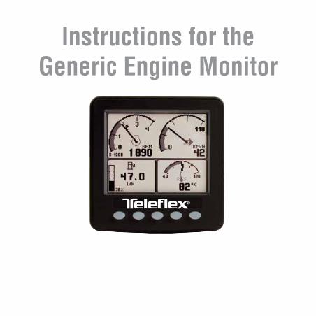
Instructions for the Generic Engine Monitor
page 1
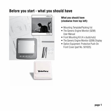
Before you start - what you should have
What you should have(clockwise from top left):
•MountingTemplate/Packinglist•TheGenericEngineMonitor(GEM) UserManual
•FrontMountingKit(4xstuds/nuts)•TheGenericEngineMonitor(GEM)Display•OptionEquipment:ProtectivePush-On FrontCover(partNo.501025)
page 2
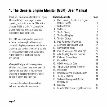
Section/Contents Page 2. UnderstandingTheGenericEngine Monitor(GEM) 3 3. GettingStarted 5 4. SoftKeys 6 5. TheTriDisplay 7 6. TheQuadDisplay 10 7. TheUniDisplay 11 8. DataParametersMonitored 12 9. ActiveandStoredAlarmLists 1710. ConfigurationMenu 1911. Pop-UpMessagesandWarnings 2512. AdjustingLightingandContrast 2613. PreferredScreenStore 2714. KeypadLock 2715. GEMConnectionData 2816. TypicalJ1939WiringTopology 3017. Installation 3118. MaintenanceandTroubleshooting 3319. TheGEMPlatform 3420. SoftwareDevelopmentOptions 34 fottheGEM21. Glossary 3522. ImportantSafetyandLegalInformation 36
1. The Generic Engine Monitor (GEM) User Manual
ThankyouforchoosingtheGenericEngineMonitor(GEM).ThesepagesprovideoperatinginstructionsfortheGEMwhichdisplaysJ1939orJ1587–compatible engine/transmissiondata.Pleaseread throughtheguidebeforeuse.
TheGEMuser-configurableapplication softwarecreatesgraphicalinstrument clusterstodisplayparametersandalarms–providinguserswithatime-savingsolution forintroducingequipmentincorporating higherdegreesofelectronicdisplay andcontrol.
Weexpectthatyouwillbeverypleased withthisproductandhavemanyyearsoftrouble-freeoperation.Ifyouhaveany problemsorideasforimprovementthen wewouldliketohearfromyou.
Formoreinformationpleasevisitour website:www.teleflexmarine.com
page 3
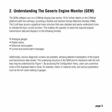
2. Understanding The Generic Engine Monitor (GEM)
TheGEMsoftwarerunsonaCANtrakdisplay(seesection19forfurtherdetailsontheCANtrakplatform)withfivesoftkeys,providingaflexibleandintuitiveHuman-MachineInterface(HMI).The5softkeysaccessagraphicalmenustructurethatusesstandardandeasily-understoodiconstoindicatethekey’scurrentfunction.Thisenablestheoperatortoselecttherequiredengine/transmissiondataanddisplayitinthefollowingformats:
•Analoguegauges•Digitalvalues•Historicaltrendgraphs•Currentandstoredalarmmessages
Additionally,variousdiagnosticscreensareavailable,allowingdetailedinvestigationoftheengineandtransmissiondatastream.TheunderlyingstructureoftheGEManditsinteractionwiththesoftkeysmaybeunderstoodbyFigure1.ByaccessingtheConfigurationmenu,userscancustomisesomeofthedisplayeddatatoshow,forexample,metricorimperialunits,andvariousparameterssuchasthefull-scalereadingofgauges.
page 4
Understanding The Generic Engine Monitor (GEM) – cont.
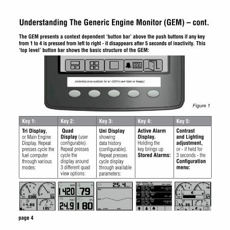
The GEM presents a context dependent ‘button bar’ above the push buttons if any key from 1 to 4 is pressed from left to right - it disappears after 5 seconds of inactivity. This ‘top level’ button bar shows the basic structure of the GEM:
Key 1: Key 2: Key 3: Key 4: Key 5:
Tri Display, orMainEngineDisplay.Repeatpressescyclethefuelcomputerthroughvariousmodes:
Quad Display(userconfigurable).Repeatpressescyclethedisplayaround3differentquadviewoptions:
Uni Display showingdatahistory(configurable).Repeatpressescycledisplaythroughavailableparameters:
Active Alarm Display. HoldingthekeybringsupStored Alarms:
Contrast and Lighting adjustment, or-ifheldfor3seconds-theConfiguration menu:
Figure 1
page 5
3. Getting Started
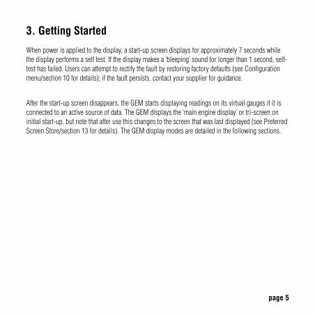
Whenpowerisappliedtothedisplay,astart-upscreendisplaysforapproximately7secondswhilethedisplayperformsaselftest.Ifthedisplaymakesa‘bleeping’soundforlongerthan1second,self-testhasfailed.Userscanattempttorectifythefaultbyrestoringfactorydefaults(seeConfigurationmenu/section10fordetails);ifthefaultpersists,contactyoursupplierforguidance.
Afterthestart-upscreendisappears,theGEMstartsdisplayingreadingsonitsvirtualgaugesifitisconnectedtoanactivesourceofdata.TheGEMdisplaysthe‘mainenginedisplay’ortri-screenoninitialstart-up,butnotethatafterusethischangestothescreenthatwaslastdisplayed(seePreferredScreenStore/section13fordetails).TheGEMdisplaymodesaredetailedinthefollowingsections.
page 6
4. Soft Keys
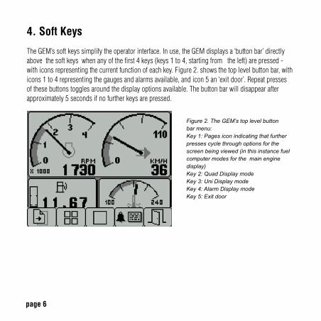
TheGEM’ssoftkeyssimplifytheoperatorinterface.Inuse,theGEMdisplaysa‘buttonbar’directlyabovethesoftkeyswhenanyofthefirst4keys(keys1to4,startingfromtheleft)arepressed-withiconsrepresentingthecurrentfunctionofeachkey.Figure2.showsthetoplevelbuttonbar,withicons1to4representingthegaugesandalarmsavailable,andicon5an‘exitdoor’.Repeatpressesofthesebuttonstogglesaroundthedisplayoptionsavailable.Thebuttonbarwilldisappearafterapproximately5secondsifnofurtherkeysarepressed.
Figure 2. The GEM’s top level button bar menu:Key 1: Pages icon indicating that further presses cycle through options for the screen being viewed (in this instance fuel computer modes for the main engine display)Key 2: Quad Display modeKey 3: Uni Display modeKey 4: Alarm Display modeKey 5: Exit door
page 7
5. The Tri Display
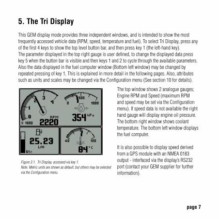
ThisGEMdisplaymodeprovidesthreeindependentwindows,andisintendedtoshowthemostfrequentlyaccessedvehicledata(RPM,speed,temperatureandfuel).ToselectTriDisplay,pressanyofthefirst4keystoshowthetoplevelbuttonbar,andthenpresskey1(theleft-handkey). Theparameterdisplayedinthetoprightgaugeisuserdefined,tochangethedisplayeddatapress key5whenthebuttonbarisvisibleandthenkeys1and2tocyclethroughtheavailableparameters.Alsothedatadisplayedinthefuelcomputerwindow(Bottomleftwindow)maybechangedbyrepeatedpressingofkey1,Thisisexplainedinmoredetailinthefollowingpages.Also,attributessuchasunitsandscalesmaybechangedviatheConfigurationmenu(Seesection10fordetails).
Figure 3.1. Tri Display, accessed via key 1. Note. Metric units are shown as default, but others may be selected via the Configuration menu.
Thetopwindowshows2analoguegauges;EngineRPMandSpeed(maximumRPMandspeedmaybesetviatheConfigurationmenu).Ifspeeddataisnotavailabletherighthandgaugewilldisplayengineoilpressure.Thebottomrightwindowshowscoolanttemperature.Thebottomleftwindowdisplaysthefuelcomputer.
ItisalsopossibletodisplayspeedderivedfromaGPSmodulewithanNMEA0183output-interfacedviathedisplay’sRS232port(contactyourGEMsupplierforfurtherinformation).
page 8
5. The Tri Display (Fuel Computer Modes)
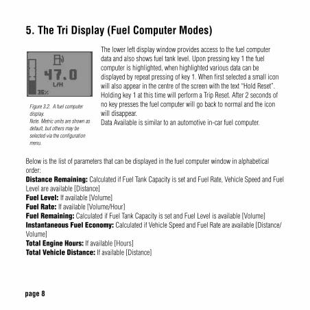
Figure 3.2. A fuel computer display.Note. Metric units are shown as default, but others may be selected via the configurationmenu.
Belowisthelistofparametersthatcanbedisplayedinthefuelcomputerwindowinalphabeticalorder:Distance Remaining:CalculatedifFuelTankCapacityissetandFuelRate,VehicleSpeedandFuelLevelareavailable[Distance]Fuel Level: Ifavailable[Volume]Fuel Rate: Ifavailable[Volume/Hour]Fuel Remaining:CalculatedifFuelTankCapacityissetandFuelLevelisavailable[Volume]Instantaneous Fuel Economy:CalculatedifVehicleSpeedandFuelRateareavailable[Distance/Volume]Total Engine Hours:Ifavailable[Hours]Total Vehicle Distance:Ifavailable[Distance]
Thelowerleftdisplaywindowprovidesaccesstothefuelcomputer dataandalsoshowsfueltanklevel.Uponpressingkey1thefuelcomputerishighlighted,whenhighlightedvariousdatacanbedisplayedbyrepeatpressingofkey1.Whenfirstselectedasmalliconwillalsoappearinthecentreofthescreenwiththetext“HoldReset”.Holdingkey1atthistimewillperformaTripReset.After2secondsofnokeypressesthefuelcomputerwillgobacktonormalandtheiconwilldisappear.DataAvailableissimilartoanautomotivein-carfuelcomputer.
page 9
5. The Tri Display (Fuel Computer Modes) – continued
Trip Distance:CalculatedsincelastTripResetifTotalVehicleDistanceisavailable[Distance]Trip Engine Hours: CalculatedsincelastTripResetifTotalEngineHoursisavailable[Hours]Trip Fuel: CalculatedsincelastTripResetifTotalFuelUsedisavailable[Volume]Trip Fuel Economy:CalculatedsincelastTripResetifTotalFuelUsedandTotalVehicleDistanceareavailable[Distance/Volume]Trip Fuel Rate:CalculatedsincelastTripResetifTotalEngineHoursandTotalFuelUsedareavailable[Volume/Hour]
Note. A Trip Reset affects all reset-able fuel computer parameters and can be performed by holding key 1 when the Hold Reset icon appears. The icon appears for approximately 2 seconds when the fuel computer window is first selected. Setting Total Fuel Tank Data and Fuel Tank Reset is performed via the Configuration menu.
page 10
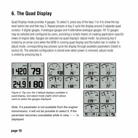
6. The Quad Display
QuadDisplaymodeprovides4gauges.Toselectit,pressanyofthekeys1to4toshowthetop levelbuttonbarandthenkey2.Repeatpressesofkey2cyclethedisplayaround3separatequadscreens:4digitalgauges,4analoguegaugesand4alternativeanaloguegauges.All12gauges maybeselectedandconfiguredbyusers,providingasimplemeansofcreatingapplication-specificviewsofenginedata.Gaugesareselectedviaquaddisplay’s‘adjustmode’,bypressingkey5 (notedbyanarrowicon)whentheGEMisrunningquaddisplayandthebuttonbarisvisible.Inadjustmode,correspondingkeypressescyclethedisplaythroughavailableparameters(listedinsection8).Theselectedconfigurationisstoredevenwhenpowerisremoved;adjustmode isexitedbypressingkey5.
Figure 4. Top row: the 3 default displays available in quad-display, and adjust mode (right) which allows users to select the gauges displayed.
Note. If a parameter is not available from the engine/transmission, it will not be possible to select it. If the parameter becomes unavailable while in view, ‘- - -‘ is displayed.
page 11
7. The Uni Display
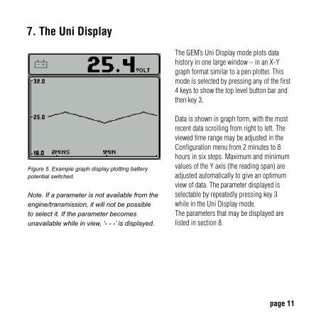
Figure 5. Example graph display plotting battery potential switched.
Note. If a parameter is not available from the engine/transmission, it will not be possible to select it. If the parameter becomes unavailable while in view, ‘- - -’ is displayed.
TheGEM’sUniDisplaymodeplotsdatahistoryinonelargewindow–inanX-Ygraphformatsimilartoapenplotter.Thismodeisselectedbypressinganyofthefirst4keystoshowthetoplevelbuttonbarandthenkey3.
Dataisshowningraphform,withthemostrecentdatascrollingfromrighttoleft.TheviewedtimerangemaybeadjustedintheConfigurationmenufrom2minutesto8hoursinsixsteps.MaximumandminimumvaluesoftheYaxis(thereadingspan)areadjustedautomaticallytogiveanoptimumviewofdata.Theparameterdisplayedisselectablebyrepeatedlypressingkey3 whileintheUniDisplaymode.Theparametersthatmaybedisplayedarelistedinsection8.
page 12
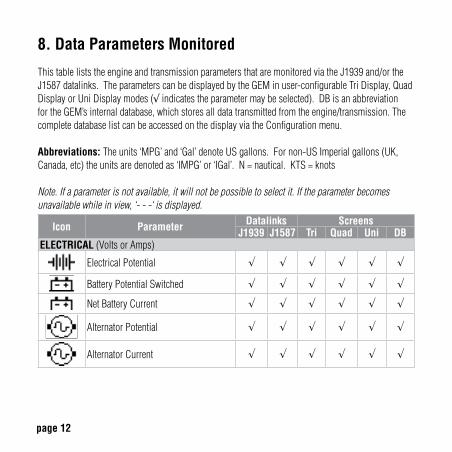
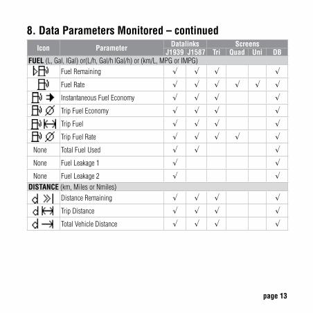
8. Data Parameters Monitored
ThistableliststheengineandtransmissionparametersthataremonitoredviatheJ1939and/ortheJ1587datalinks.TheparameterscanbedisplayedbytheGEMinuser-configurableTriDisplay,QuadDisplayorUniDisplaymodes(√ indicatestheparametermaybeselected).DBisanabbreviationfortheGEM’sinternaldatabase,whichstoresalldatatransmittedfromtheengine/transmission.ThecompletedatabaselistcanbeaccessedonthedisplayviatheConfigurationmenu.
Abbreviations: Theunits‘MPG’and‘Gal’denoteUSgallons.Fornon-USImperialgallons(UK,Canada,etc)theunitsaredenotedas‘IMPG’or‘IGal’.N=nautical.KTS=knots
Note. If a parameter is not available, it will not be possible to select it. If the parameter becomes unavailable while in view, ‘- - -‘ is displayed.
Icon Parameter Datalinks ScreensJ1939 J1587 Tri Quad Uni DB
ELECTRICAL(VoltsorAmps)
ElectricalPotential √ √ √ √ √ √
BatteryPotentialSwitched √ √ √ √ √ √
NetBatteryCurrent √ √ √ √ √ √
AlternatorPotential √ √ √ √ √ √
AlternatorCurrent √ √ √ √ √ √
page 13
Icon Parameter Datalinks ScreensJ1939 J1587 Tri Quad Uni DB
FUEL(L,Gal,lGal)or(L/h,Gal/hIGal/h)or(km/L,MPGorIMPG)FuelRemaining √ √ √ √
FuelRate √ √ √ √ √ √
InstantaneousFuelEconomy √ √ √ √
TripFuelEconomy √ √ √ √
TripFuel √ √ √ √
TripFuelRate √ √ √ √ √
None TotalFuelUsed √ √ √
None FuelLeakage1 √ √
None FuelLeakage2 √ √DISTANCE(km,MilesorNmiles)
DistanceRemaining √ √ √ √
TripDistance √ √ √ √
TotalVehicleDistance √ √ √ √
8. Data Parameters Monitored – continued
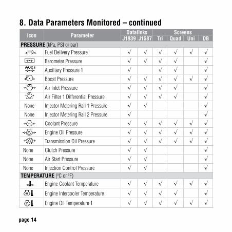
page 14
Icon Parameter Datalinks ScreensJ1939 J1587 Tri Quad Uni DB
PRESSURE(kPa,PSIorbar)FuelDeliveryPressure √ √ √ √ √ √BarometerPressure √ √ √ √ √AuxiliaryPressure1 √ √ √ √BoostPressure √ √ √ √ √ √AirInletPressure √ √ √ √ √AirFilter1DifferentialPressure √ √ √ √ √
None InjectorMeteringRail1Pressure √ √ √None InjectorMeteringRail2Pressure √ √ CoolantPressure √ √ √ √ √ √
EngineOilPressure √ √ √ √ √ √TransmissionOilPressure √ √ √ √ √ √
None ClutchPressure √ √ √None AirStartPressure √ √ √None InjectionControlPressure √ √ √TEMPERATURE(ºCorºF)
EngineCoolantTemperature √ √ √ √ √ √
EngineIntercoolerTemperature √ √ √ √ √
EngineOilTemperature1 √ √ √ √ √ √
8. Data Parameters Monitored – continued
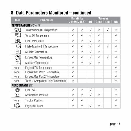
page 15
Icon Parameter Datalinks ScreensJ1939 J1587 Tri Quad Uni DB
TEMPERATURE(ºCorºF)TransmissionOilTemperature √ √ √ √ √ √
TurboOilTemperature √ √ √ √ √
FuelTemperature √ √ √ √ √
IntakeManifold1Temperature √ √ √ √ √ √
AirInletTemperature √ √ √ √ √
ExhaustGasTemperature √ √ √ √ √ √
AuxiliaryTemperature1 √ √ √ √ √None EngineECUTemperature √ √None ExhaustGasPort1Temperature √ √None ExhaustGasPort2Temperature √ √None Turbo1CompressorInletTemperature √ √PERCENTAGE(%)
FuelLevel √ √ √ √AccelerationPosition √ √ √ √ √
None ThrottlePosition √ √ √
EngineOilLevel √ √ √ √ √
8. Data Parameters Monitored – continued
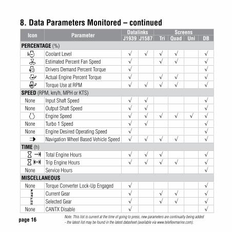
page 16
Icon Parameter Datalinks ScreensJ1939 J1587 Tri Quad Uni DB
PERCENTAGE(%)CoolantLevel √ √ √ √ √EstimatedPercentFanSpeed √ √ √ √DriversDemandPercentTorque √ √ActualEnginePercentTorque √ √ √ √TorqueUseatRPM √ √ √ √ √
SPEED(RPM,km/h,MPHorKTS)None InputShaftSpeed √ √ √None OutputShaftSpeed √ √ √ EngineSpeed √ √ √ √ √ √None Turbo1Speed √ √ √None EngineDesiredOperatingSpeed √ √
NavigationWheelBasedVehicleSpeed √ √ √ √ √TIME(h)
TotalEngineHours √ √ √ √TripEngineHours √ √ √ √ √
None ServiceHours √MISCELLANEOUSNone TorqueConverterLock-UpEngaged √ √
CurrentGear √ √ √ √SelectedGear √ √ √ √
None CANTXDisable √ √Note. This list is current at the time of going to press, new parameters are continually being added - the latest list may be found in the latest datasheet (available via www.teleflexmarine.com).
8. Data Parameters Monitored – continued
page 17
9. Active and Stored Alarm Lists
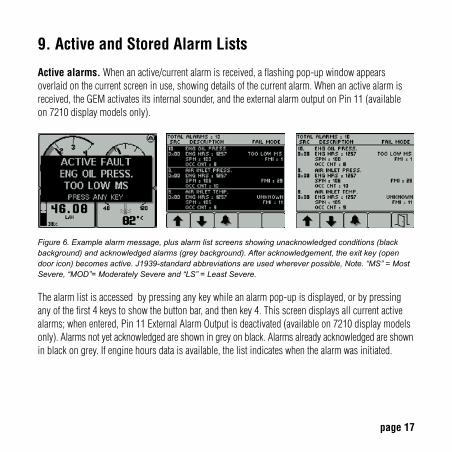
Active alarms.Whenanactive/currentalarmisreceived,aflashingpop-upwindowappearsoverlaidonthecurrentscreeninuse,showingdetailsofthecurrentalarm.Whenanactivealarmisreceived,theGEMactivatesitsinternalsounder,andtheexternalalarmoutputonPin11(available on7210displaymodelsonly).
Figure 6. Example alarm message, plus alarm list screens showing unacknowledged conditions (black background) and acknowledged alarms (grey background). After acknowledgement, the exit key (open door icon) becomes active. J1939-standard abbreviations are used wherever possible, Note. “MS” = Most Severe, “MOD”= Moderately Severe and “LS” = Least Severe.
Thealarmlistisaccessedbypressinganykeywhileanalarmpop-upisdisplayed,orbypressinganyofthefirst4keystoshowthebuttonbar,andthenkey4.Thisscreendisplaysallcurrentactivealarms;whenentered,Pin11ExternalAlarmOutputisdeactivated(availableon7210displaymodelsonly).Alarmsnotyetacknowledgedareshowningreyonblack.Alarmsalreadyacknowledgedareshowninblackongrey.Ifenginehoursdataisavailable,thelistindicateswhenthealarmwasinitiated.
page 18
9. Active and Stored Alarm Lists – continued
Whenfirstenteringthescreen,thelistautomaticallydisplaysthemostrecentalarm.Thelistcanbescrolledusingkeys1and2.Thisscreencannotbeexiteduntilallalarmshavebeenacknowledged bypressingkey3.Alarmmessagesareautomaticallyclearedfromthelistwhennolongerreceived bytheGEM.
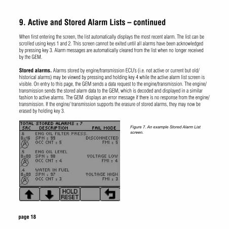
Stored alarms.Alarmsstoredbyengine/transmissionECU’s(i.e.notactiveorcurrentbutold/historicalalarms)maybeviewedbypressingandholdingkey4whiletheactivealarmlistscreenisvisible.Onentrytothispage,theGEMsendsadatarequesttotheengine/transmission.Theengine/transmissionsendsthestoredalarmdatatotheGEM,whichisdecodedanddisplayedinasimilarfashiontoactivealarms.TheGEMdisplaysanerrormessageifthereisnoresponsefromtheengine/transmission.Iftheengine/transmissionsupportstheerasureofstoredalarms,theymaynowbeerasedbyholdingkey3.
Figure 7. An example Stored Alarm List screen.
page 19
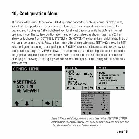
10. Configuration Menu
ThismodeallowsuserstosetvariousGEMoperatingparameterssuchasimperialormetricunits,scalelimitsforspeedometer,engineserviceinterval,etc.Theconfigurationmenuisenteredbypressingandholdingkey5(therighthandkey)foratleast3secondswhiletheGEMisinnormaloperatingmode.Thetoplevelconfigurationmenuwillbedisplayedasshown.Keys1and2thenallowyoutochoosefromSETTINGS,SYSTEMorDbVIEWER(Thechosenitemishighlightedinboldwithanarrowpointingtoit).Pressingkey4entersthechosensub-menu.SETTINGSallowstheGEMtobeconfiguredaccordingtouserpreferences.SYSTEMaccessesmaintenanceandlowlevelsystemconfigurationsettings.DbVIEWERallowstheusertoviewalldata(includingthatcannotbefoundinthegraphicalscreens)thattheGEMdecodes.Eachofthesesub-menusisdescribedinmoredetailonthepagesfollowing.Pressingkey5exitsthecurrentmenu/sub-menu.Settingsareautomaticallystoredonexit.
---------
Figure 8. The top level Configuration menu and its three choices of SETTINGS, SYSTEM and Db VIEWER sub-menus. Pressing Key 4 enters the menu highlighted. Key 5 (‘exit door’ - the right hand button) returns you to the previous menu.
page 20
10. Settings Sub-Menu (2nd Level Configuration Menu)
Thesettingsmenuallowstheusertoentersub-levelscreenstoconfigure:Units: Thismenuenablestheusertosettheunitsusedforspeed,distance,pressure,volumeandtemperature.LangUage:Choosefromvariouslanguages.BLeep:Whenactivated,thesoftkeyswillemitanaudible“bleep”.Usethismenutoswitchthefunctionon/off.Anaudible“bleep”willstillsoundifanalarmoccurs.DispLay:Thedisplaymenuallowstheusertoconfigurecertainvisualparametersandcontrolsofthedisplay.
MaX RpM: ThisdefinesandrestrictstheupperlimitoftheRPMgaugesdisplayedthroughouttheGEM.MaX speeD:ThisdefinesandrestrictstheupperlimitoftheSpeedgaugesdisplayedthroughouttheGEM.gRapH Range:ThischangestheresolutionofthehistoricdatadisplayedintheUniDisplay.QUaD aDJUst: Thissettingallowstheusertodisablethe‘adjustmode’featureintheQuadDisplays.Thisisgenerallyusedforuserswhowouldliketofixtheparametersdisplayedonthescreensoncetheyarehappywiththem.Thiscanbere-enabledatanytime.seRvice: Settheserviceintervalinhoursandresettheintervalcounter.ItisimportanttonotethatsettingSERVICEto0willdisabletheserviceintervalfunctionandtheword“OFF”willbedisplayed.FUeL capacity:Thefuelcapacityscreenallowstheusertoenterthefueltankcapacityofthevehicle.Bydefaultthefueltankcapacitywillbesetto0.OnlyafterthishasbeensetwilltheparametersFuelRemainingandDistanceRemainingbecalculated.
page 21
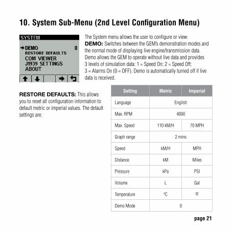
10. System Sub-Menu (2nd Level Configuration Menu)
TheSystemmenuallowstheusertoconfigureorview:DeMo: SwitchesbetweentheGEM’sdemonstrationmodesandthenormalmodeofdisplayingliveengine/transmissiondata. DemoallowstheGEMtooperatewithoutlivedataandprovides 3levelsofsimulationdata:1=SpeedOn;2=SpeedOff; 3=AlarmsOn(0=OFF).Demoisautomaticallyturnedoffiflivedataisreceived.
Setting Metric Imperial
Language English
Max.RPM 4000
Max.Speed 110kM/H 70MPH
Graphrange 2mins
Speed kM/H MPH
Distance kM Miles
Pressure kPa PSI
Volume L Gal
Temperature ºC ºF
DemoMode 0
RestoRe DeFaULts:Thisallowsyoutoresetallconfigurationinformationtodefaultmetricorimperialvalues.Thedefaultsettingsare:
page 22
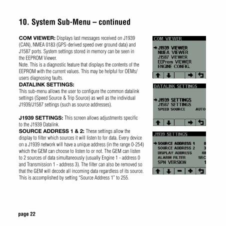
10. System Sub-Menu – continued coM vieweR:DisplayslastmessagesreceivedonJ1939(CAN),NMEA0183(GPS-derivedspeedovergrounddata)andJ1587ports.Systemsettingsstoredinmemorycanbeseenin theEEPROMViewer.Note.ThisisadiagnosticfeaturethatdisplaysthecontentsoftheEEPROMwiththecurrentvalues.ThismaybehelpfulforOEMs/usersdiagnosingfaults.DataLink settings: Thissub-menuallowstheusertoconfigurethecommondatalinksettings(SpeedSource&TripSource)aswellastheindividualJ1939/J1587settings(suchassourceaddresses).
J1939 settings: ThisscreenallowsadjustmentsspecifictotheJ1939Datalink.soURce aDDRess 1 & 2: Thesesettingsallowthedisplaytofilterwhichsourcesitwilllistentofordata.EverydeviceonaJ1939networkwillhaveauniqueaddress(intherange0-254)whichtheGEMcanchoosetolistentoornot.TheGEMcanlistento2sourcesofdatasimultaneously(usuallyEngine1-address0andTransmission1-address3).ThefiltercanalsoberemovedsothattheGEMwilldecodeallincomingdataregardlessofitssource.Thisisaccomplishedbysetting“SourceAddress1”to255.
page 23
10. System Sub-Menu – continued
DispLay aDDRess:Asmentionedpreviously,everydevicehasauniqueaddressandtheGEMisnodifferent.Insingleenginesetupsthedefaultdisplayaddressis40(SAErecommendation).IftheGEMdoesnotdisplayallnecessarydata(whichissupported)pleasecontactyourenginemanufacturerforadviceonthevalueofthissetting.aLaRM FiLteR:ThissettingspecifieswhethertheGEMwillmonitoranddisplayalarmsfromallsources(GLB,global)oronlythesourceaddress’specifiedinthesettingsSourceAddress1&2(SRC,source).spn veRsion:SettheSuspectParameterNumber[Version1,2or3].Version4is automaticallydetected,butolderengineswillhavetobesetto1,2or3.Note.ConsultyourenginesuppliertoestablishwhichSPNversionisappropriateifyouhaveproblemsreadingalarmdata.
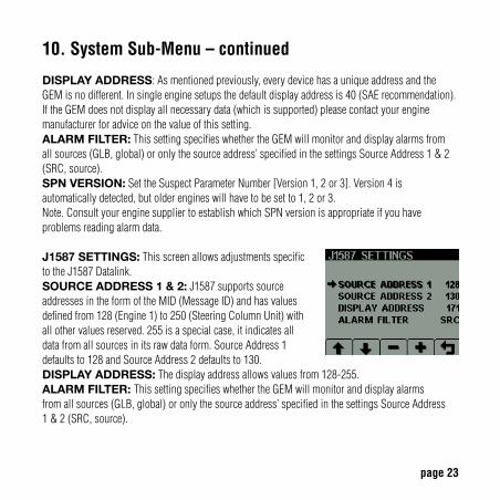
J1587 settings: ThisscreenallowsadjustmentsspecifictotheJ1587Datalink.soURce aDDRess 1 & 2:J1587supportssourceaddressesintheformoftheMID(MessageID)andhasvaluesdefinedfrom128(Engine1)to250(SteeringColumnUnit)withallothervaluesreserved.255isaspecialcase,itindicatesalldatafromallsourcesinitsrawdataform.SourceAddress1defaultsto128andSourceAddress2defaultsto130.DispLay aDDRess:Thedisplayaddressallowsvaluesfrom128-255.aLaRM FiLteR: ThissettingspecifieswhethertheGEMwillmonitoranddisplayalarms fromallsources(GLB,global)oronlythesourceaddress’specifiedinthesettingsSourceAddress 1&2(SRC,source).
page 24
10. System Sub-Menu – continued
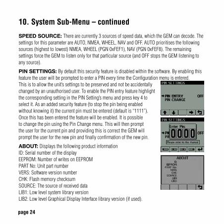
speeD soURce: Therearecurrently3sourcesofspeeddata,whichtheGEMcandecode.ThesettingsforthisparameterareAUTO,NMEA,WHEEL,NAVandOFF.AUTOprioritisesthefollowingsources(highesttolowest)NMEA,WHEEL(PGN0xFEF1),NAV(PGN0xFEF8).TheremainingsettingsforcetheGEMtolistenonlyforthatparticularsource(andOFFstopstheGEMlisteningtoanysource).
pin settings: Bydefaultthissecurityfeatureisdisabledwithinthesoftware.ByenablingthisfeaturetheuserwillbepromptedtoenteraPINeverytimetheConfigurationmenuisentered.Thisistoallowtheunit’ssettingstobepreservedandnotbeaccidentallychangedbyanunauthoriseduser.ToenablethePINentryfeaturehighlightthecorrespondingsettinginthePINSetting’smenuandpresskey4toselectit.Asanaddedsecurityfeature(tostopthepinbeingenabledwithoutknowingit)thecurrentpinmustbeentered(defaultis“1111”).Oncethishasbeenenteredthefeaturewillbeenabled.ItispossibletochangethepinusingthePinChangemenu.ThiswillthenprompttheuserforthecurrentpinandprovidingthisiscorrecttheGEMwill prompttheuserforthenewpinandfinallyconfirmationofthenewpin.
aBoUt: DisplaysthefollowingproductinformationID:SerialnumberofthedisplayEEPROM:NumberofwritesonEEPROMPARTNo:UnitpartnumberVERS:SoftwareversionnumberCHK:FlashmemorychecksumSOURCE:ThesourceofreceiveddataLIB1:LowlevelsystemlibraryversionLIB2:LowlevelGraphicalDisplayInterfacelibraryversion(ifused).
page 25
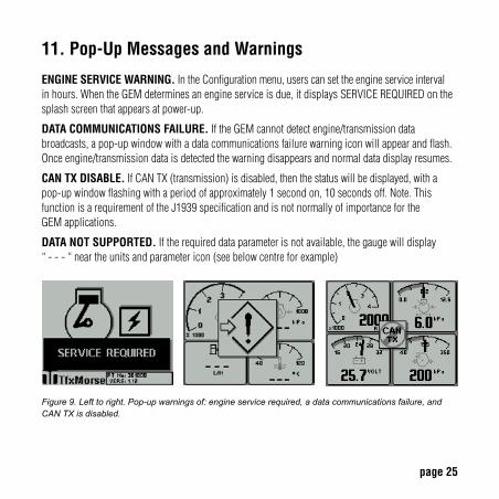
11. Pop-Up Messages and Warnings
ENGINE SERvICE WARNING.IntheConfigurationmenu,userscansettheengineserviceintervalinhours.WhentheGEMdeterminesanengineserviceisdue,itdisplaysSERVICEREQUIREDonthesplashscreenthatappearsatpower-up.
DATA COMMUNICATIONS FAILURE.IftheGEMcannotdetectengine/transmissiondatabroadcasts,apop-upwindowwithadatacommunicationsfailurewarningiconwillappearandflash.Onceengine/transmissiondataisdetectedthewarningdisappearsandnormaldatadisplayresumes.
CAN TX DISABLE.IfCANTX(transmission)isdisabled,thenthestatuswillbedisplayed,withapop-upwindowflashingwithaperiodofapproximately1secondon,10secondsoff.Note.ThisfunctionisarequirementoftheJ1939specificationandisnotnormallyofimportanceforthe GEMapplications.
DATA NOT SUPPORTED.Iftherequireddataparameterisnotavailable,thegaugewilldisplay“---“neartheunitsandparametericon(seebelowcentreforexample)
Figure 9. Left to right. Pop-up warnings of: engine service required, a data communications failure, and CAN TX is disabled.

page 26
12. Adjusting Lighting and Contrast
Pressingkey5(theright-handkey)whenthemenuiconsarenotbeingdisplayedbringsupthelightingandcontrastmenu.TheLCDhasanumberofback-lightinglevelsthatallowthedisplay tobereadinthedark.Theappropriatelevelisselectedbypressingkeys1or2todecreaseorincreaseillumination.Contrastisadjustedinthesamemanner,usingkeys3and4(Figure10). Note.TheGEMmonitorsthetemperatureoftheLCDandautomaticallyadjustsdisplaycontrastasrequired,thereforeitisnotlikelythatauserwillneedtomakeamanualcontrastadjustmentunlessextremeclimatechangesoccur.Themenuisexitedbypressingkey5.Thelightingandcontrastsettingsareretainedaftertheunitisswitchedoff.
Note. Resetting contrast. If the contrast has been adjusted poorly, you may restore the factory setting (a central value) by pressing keys 1 to 4 simultaneously. This action does not change other user-configured settings.
Figure 10. The lighting and contrast adjust screen, showing a contrast level adjustment in progress.
page 27
13. Preferred Screen Store
TheGEMautomaticallystoresthecurrentscreenasauser’spreferredpage,afteradelayofapproximately15seconds(ifnobuttonsarepushed).Onnextpower-upthedisplaywillstartwiththesplashscreen,andthengotothelaststoredscreen.Note.SelectingRestoreDefaultsontheSystemssub-menuofConfigurationwillsetthemainenginescreenasthedefaultdisplay.
14. Keypad Lock
TheGEM’sfivekeyscanbelocked,suchthatanoperatorcannotchangeanysettingsoraccess anyotherdisplaymode.(inasimilarmannertothekeylockfunctionsonamobilephone).Thisisachievedbypressingandholdingkeys1and5simultaneouslyforonesecond.RepeatingthisoperationresetstheGEM/CANtrakbacktonormaloperation.
page 28
15. GEM Connection Data
TheGEMinterfacestodataviatheDeutschDT0412PAconnectorontherearofthedisplay-wiredasshown.Connectingharnesspart#510626isavailablethroughyourlocalmarinepartsdealer,oryoumaysourcetheconnectorcomponentsfromDeutschdirectly.
• DT0612SA,matingconnector• W12S,Wedgelock(oneperconnector)• 0462-201-1631,pinsockets(notethatdifferentfinishesandterminationmethodsmaybeselected)• 114017,sealingplug(oneperunusedpinlocation)
Note.AferriteclampmustbeplacedovertheharnesstomeetEMCradiationemissionrequirementsofBSEN60945(Maritimenavigation&radiocommunicationequipment&systems).WerecommendthattheclampshouldbeaTDKZCAT2032-0930,aMulticomp33RH175x285x107:core,10.7mmIDorequivalent.
page 29
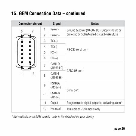
15. GEM Connection Data – continued
Connector pin-out Signal Notes
6 7
1 12
1 Power- Ground&power(10-30VDC).Supplyshouldbeprotectedby500mA-ratedcircuitbreaker/fuse2 Power+
3 TX(+)
RS-232serialport4 TX(-)
5 RX(-)
6 RX(+)
7CANLO(J1939LO)
CAN2.0Bport
8CANHI(J1939HI)
9RS485A(J1587+)
Serialport
10RS485B(J1587-)
11 Output Programmabledigitaloutputforactivatingalarm*
12 Notused Availableon7210modelonly
* Not available on all GEM models - refer to the datasheet for your display.
page 30
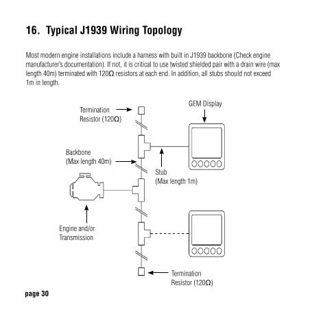
16. Typical J1939 Wiring Topology
MostmodernengineinstallationsincludeaharnesswithbuiltinJ1939backbone(Checkenginemanufacturer’sdocumentation).Ifnot,itiscriticaltousetwistedshieldedpairwithadrainwire(maxlength40m)terminatedwith120Ωresistorsateachend.Inaddition,allstubsshouldnotexceed 1minlength.
Engineand/orTransmission
Termination Resistor(120Ω)
TerminationResistor(120Ω)
Stub(Maxlength1m)
Backbone(Maxlength40m)
GEMDisplay
page 31
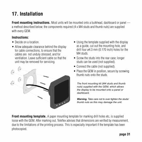
17. Installation
Front mounting instructions.Mostunitswillbemountedontoabulkhead,dashboardorpanel—amethoddescribedbelow;thecomponentsrequired(4xM4studsandthumbnuts)aresupplied witheveryGEM.
Front mounting template.Apapermountingtemplateformarkingdrillholesetc,issuppliedloosewiththeGEM.Aftermarkingout,Teleflexadvisesthatdimensionsareverifiedbymeasurement,duetothelimitationsoftheprintingprocess.Thisisespeciallyimportantifthetemplatehasbeenphotocopied.
The front mounting kit (M4 studs and thumb nuts) supplied with the GEM, which allows the display to be mounted onto a panel or dashboard.
Warning. Take care not to over tighten the studs/thumb nuts as this may damage the unit.
Instructions:•Decideonalocation.•Allowadequateclearancebehindthedisplayforcableconnections,toensurethatthecablesarenotundulystressed,andforventilation.Leavesufficientcablesothattheunitmayberemovedforservicing.
•Usingthetemplatesuppliedwiththedisplayasaguide,cutoutthemountinghole,anddrillfourø4.3mm(0.170inch)holesfortheM4studs.
•Screwthestudsintotherearcase;longerstudscanbeused(notsupplied).
•Connectthecable(notsupplied).•PlacetheGEMinposition,securebyscrewingthumbnutsontothestuds.
page 32
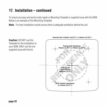
17. Installation – continued
ToensureaccuracyandavoidcostlyrepairsaMountingTemplateissuppliedloosewiththeGEM.BelowisanexampleofthisMountingTemplate.
Note.Forbestinstallationresultsensurethereisadequateventilationbehindtheunit.
FOR
REFER
ENCE
ONLY
Caution:DONOTusethisTemplatefortheinstallationofyourGEM,ONLYusetheonesuppliedloosewiththekit.
page 33
18. Maintenance and Troubleshooting
Noregularmaintenanceisrequired,exceptforcleaningtheGEMlensasrequiredusingasoft,dampcloth.Donotuseabrasivematerialsorsolvents,specificallywhitespirit,petrolandacetone.Shouldanyfurtherattentionbenecessary,pleasecontactyoursupplier.IfyouareexperiencingoperatingproblemswiththeGEM,checkthesediagnostics:
Problem Possible solution
Unitdoesnotpowerup Ensureconnectionstounitarecorrect.Ensurepowersourceispresent.
Displayisblankorblack Adjust/resetlightingandcontrastsettings.Ensuretemperatureiswithinoperatingrangeoftheunit.
Unitbleepsatstart-upanddoesnotstoresettings
Unithasfailedself-test.ContactyourGEMsupplier
Unitfailstodisplayanydata Ensureconnectionstounitarecorrect.EnsuredatasourcesupportsJ1939orJ1587messageprotocol.
Unitfailstodisplaycertainparameter(s)/unabletoselectcertainparameter(s)
EnsuretheGEMsupportsrequiredparameter(s)Ensuredatasourceprovidesrequiredparameter(s).
Activealarmmessagesarenotdisplayed
Ensuredatasourceprovidesalarmmessagedatainthefollowingformat:J1939ActiveDiagnosticTroubleCodes-DiagnosticMessage1(DM1).
Storedalarmmessagesarenotdisplayed
Ensuredatasourceprovidesalarmmessagedatainthefollowingformat:J1939ActiveDiagnosticTroubleCodes-DiagnosticMessage2(DM2).
page 34
20. Software Development Options for the GEM
CustomershavearangeofoptionsforcreatinguserinterfacesonGEM:LikeaPC,aGEMneedsapplicationsoftwaretoprovideausefulfunction.OneexampleofapplicationsoftwarewrittenbyTeleflexistheGEM(GenericEngineMonitoring)softwarewrittentodisplayelectronicallycontrolleddieselenginesandtransmissionperformanceparametersandfaults/alarmusingtheSAEJ1939andJ1587protocol.GEMsmaybeprogrammedtoperformaninfinitenumberofdisplay,controlanddataloggingtasks.GEMsmaybeprogrammedtoperformmanydisplay,control,anddataloggingtasks.PleasecontactTeleflexMarinewithyourspecificrequirementsforadditionaldetails.
19. The GEM Platform
TeleflexGEMLCDdisplaysarerugged110x110mmDIN-formatmoduleswith5softkeys,andoffera160x128pixeldisplayarea.Thisislargeenoughtoprovidegreatflexibilityformanagingtherichdataavailablefrommodernelectronicallycontrolledsystems.GEMisnowinitsfourthgeneration:thelatestGEM7200familyemploysdesign-for-manufacturetechniquesincludingchip-on-tabtominimisecomponentcountandassemblyoperations.TheGEM7200seriesofdisplaysemployfilmsupertwistnematicLCDsforvisibilityindirectsunlight–withbacklighting.
TheGEMdisplayfeaturesaDeutschconnectorinterfacewhichallowstheunittoprovideingressprotectiontoIP67,coveringimmersioninwaterupto1meterdeep.Unitscomewith3serialinterfaces:RS-232,RS-485,andaCAN2.0BportcompatiblewiththeJ1939protocolusedbymanymanufacturers.
Differencesbetween7200and7210: 7200operatesbetween-25°Cto+75°C. 7210incorporatesaheatingelementallowingoperationbetween-40°Cto+75°C.
TheGEM7210alsoincludesaprogrammable500mADigitalOutputDriver.
Datasheetsareavailableat:www.teleflexmarine.com
page 35
21. Glossary
CAN ControllerAreaNetwork(alsoreferredtoasCANbus);serialcommunicationsprotocolforautomotiveuseCANtrak IntelligentCAN-compatibleLCDdisplaymoduleFMIFailureModeIdentifierGPS GlobalPositioningSystemHMI Human-MachineInterfaceISO InternationalStandardOrganisationJ1939 SAEenginedataprotocolusingCAN2.0BJ1587 ElectronicDataInterchangebetweenMicrocomputerSystemsinHeavy-DutyVehicle ApplicationsLCD LiquidCrystalDisplayNMEA NationalMarineElectronicsAssociation;serialcommunicationsprotocolfor marineusePID ParameterIdentifierRS-232 StandardelectricalinterfaceforserialcommunicationsRS-485 StandarddifferentialelectricalinterfaceforserialcommunicationsSAE SocietyofAutomotiveEngineersInc.SID SubsystemIdentifierSoftkeys Push-buttonkeyswhosefunctionchangesaccordingtouseSPN SuspectParameterNumber:J1939-specificfaultcodeIDnumber
Note. The messages, icons, error codes etc displayed by the GEM conform to J1939 standards wherever possible. A copy of the relevant standards documents will be important for developers - they may be accessed and purchased via: www.sae.org/standardsdev/groundvehicle/j1939a.htm

page 36
22. Important Safety and Legal Information
UndernocircumstancesshallTeleflexoranyofitssubsidiarycompaniesacceptliabilityforanylossofdata,income,incidentaldamageorconsequentiallossesincurredasaresultoftheuseoftheproducthowsoevercausedwhenusedasamonitorforelectronically-controlledengines/transmissionsorothersystems.•Reproduction,transfer,distributionorstorageofpartorallofthecontentsinthisdocumentin anyformwithoutwrittenpermissionofTeleflexisprohibited.
•Teleflexoperatesapolicyofcontinuousimprovement.TeleflexreservestherighttoalterandimprovetheCANtrakdisplaysandtheGEMsoftwarewithoutpriornotice. Liquid crystal safety.Iftheliquidcrystaldisplay(LCD)isbroken,particularcaremustbetakenwithanyleakingfluid.Urgentactionmustbetaken:
•IftheLCDfluidgetsontoyourskinwipeimmediatelywithasuitableclothandwashthearea wellwithmildsoapandwater.
•IftheLCDfluidgetsintoyoureyethoroughlyrinseyoureyewithcleanwaterforseveralminutesandthengainimmediatemedicalassistance.
•IftheLCDfluidisswallowedrinseyourmouththoroughlywithcleanwaterthendrinkasubstantialvolumeofwaterandmakeyourselfvomit.Thengainimmediatemedicalassistance. CE EMC Directive 89/336/EE.Thisproducthasbeendesignedtobecompliantwiththisdirective.Compliancecanonlybeensuredbycorrectinstallation.


Teleflex Marine3831 No. 6 Road,Richmond,Brit ish Columbia,V6V 1P6CanadaTel: (001) 604-270-6899Fax: (001) 604-270-7172Email : [email protected]
www.teleflexmarine.com
©2005 Marine Canada Acquisition Limited PartnershipDBA Teleflex Canada. Specifications subject to change without notice.Any trademarks used are recognised.
Part Number 806612 Rev. 07August 2012
M A R I N E