
GEH-6860 Mark VIeS Control General Market Functional ... · The Mark VIeS Functional Safety System...
132
GEH-6860 Mark* VIeS Control General Market Functional Safety Manual July 2019 Public Information
Transcript of GEH-6860 Mark VIeS Control General Market Functional ... · The Mark VIeS Functional Safety System...

GEH-6860
Mark* VIeS ControlGeneral MarketFunctional Safety Manual
July 2019
Public Information

These instructions do not purport to cover all details or variations in equipment, nor to provide for every possiblecontingency to be met during installation, operation, and maintenance. The information is supplied for informationalpurposes only, and GE makes no warranty as to the accuracy of the information included herein. Changes, modifications,and/or improvements to equipment and specifications are made periodically and these changes may or may not be reflectedherein. It is understood that GE may make changes, modifications, or improvements to the equipment referenced herein or tothe document itself at any time. This document is intended for trained personnel familiar with the GE products referencedherein.
GE may have patents or pending patent applications covering subject matter in this document. The furnishing of thisdocument does not provide any license whatsoever to any of these patents.
Public Information – This document contains non-sensitive information approved for public disclosure.
GE provides the following document and the information included therein as is and without warranty of any kind,expressed or implied, including but not limited to any implied statutory warranty of merchantability or fitness forparticular purpose.
For further assistance or technical information, contact the nearest GE Sales or Service Office, or an authorized GE SalesRepresentative.
Issued: July 2019
© 2019 General Electric Company.___________________________________* Indicates a trademark of General Electric Company and/or its subsidiaries.All other trademarks are the property of their respective owners.
We would appreciate your feedback about our documentation.Please send comments or suggestions to [email protected]
Public Information
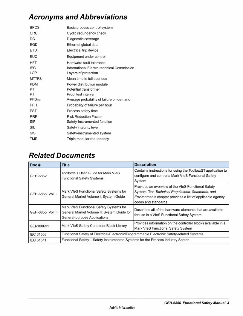
Acronyms and AbbreviationsBPCS Basic process control systemCRC Cyclic redundancy checkDC Diagnostic coverageEGD Ethernet global dataETD Electrical trip device
EUC Equipment under control
HFT Hardware fault toleranceIEC International Electro-technical CommissionLOP Layers of protectionMTTFS Mean time to fail spuriousPDM Power distribution modulePT Potential transformerPTI Proof test intervalPFDavg Average probability of failure on demandPFH Probability of failure per hourPST Process safety timeRRF Risk Reduction FactorSIF Safety-instrumented functionSIL Safety integrity levelSIS Safety-instrumented systemTMR Triple modular redundancy
Related DocumentsDoc # Title Description
GEH-6862ToolboxST User Guide for Mark VIeSFunctional Safety Systems
Contains instructions for using the ToolboxSTapplication toconfigure and control a Mark VIeS Functional SafetySystem
GEH-6855_Vol_IMark VIeS Functional Safety Systems forGeneral Market Volume I: System Guide
Provides an overview of the VIeS Functional SafetySystem. The Technical Regulations, Standards, andEnvironments chapter provides a list of applicable agencycodes and standards
GEH-6855_Vol_IIMark VIeS Functional Safety Systems forGeneral Market Volume II: System Guide forGeneral-purpose Applications
Describes all of the hardware elements that are availablefor use in a VIeS Functional Safety System
GEI-100691 Mark VIeS Safety Controller Block LibraryProvides information on the controller blocks available in aMark VIeS Functional Safety System
IEC 61508 Functional Safety of Electrical/Electronic/Programmable Electronic Safety-related SystemsIEC 61511 Functional Safety – Safety Instrumented Systems for the Process Industry Sector
GEH-6860 Functional Safety Manual 3Public Information

Safety Symbol Legend
Warning
Indicates a procedure or condition that, if not strictly observed, could result inpersonal injury or death.
Caution
Indicates a procedure or condition that, if not strictly observed, could result in damageto or destruction of equipment.
Attention
Indicates a procedure or condition that should be strictly followed to improve theseapplications.
4 GEH-6860 GEH-6860 MMark VIeS Control General Market Functional Safety ManualPublic Information
Contents1 Introduction ....................................................................................................................................... 72 Functional Safety.............................................................................................................................. 92.1 Risk Reduction........................................................................................................................................92.2 Modes of Operation ............................................................................................................................... 112.3 Hazard and Risk Analysis........................................................................................................................ 112.4 Safety Life Cycle................................................................................................................................... 122.5 Functional Safety Management ................................................................................................................ 12
3 System Design ................................................................................................................................ 133.1 Primary Architecture Components ............................................................................................................ 143.2 Safety-instrumented Functions (SIF) ......................................................................................................... 163.3 Online SIFs .......................................................................................................................................... 283.4 Redundancy.......................................................................................................................................... 293.5 Control and Protection ............................................................................................................................ 363.6 Critical System Timing Parameters ........................................................................................................... 393.7 Failure Analysis Probability..................................................................................................................... 463.8 System Configuration ............................................................................................................................. 473.9 Power Sources ...................................................................................................................................... 53
4 Installation, Commissioning, and Operation .......................................................................... 554.1 Installation ........................................................................................................................................... 554.2 Commissioning ..................................................................................................................................... 554.3 Operation ............................................................................................................................................. 564.4 Product Life.......................................................................................................................................... 58
5 I/O Configuration ............................................................................................................................ 595.1 YAIC .................................................................................................................................................. 605.2 YDIA .................................................................................................................................................. 645.3 YDOA................................................................................................................................................. 665.4 YVIB .................................................................................................................................................. 695.5 YUAA................................................................................................................................................. 78
6 Proof Tests ....................................................................................................................................... 916.1 Proof Test Requirements ......................................................................................................................... 926.2 YAIC Test Procedures ............................................................................................................................ 936.3 YDIATest Procedures ............................................................................................................................ 976.4 YDOATest Procedures ........................................................................................................................... 996.5 YUAATest Procedures ..........................................................................................................................1036.6 YVIB Test Procedures ...........................................................................................................................115
Appendix: Determine Frame Input Client Completion Time....................................................123Glossary of Terms ..............................................................................................................................127
GEH-6860 Functional Safety Manual 5Public Information

Notes
6 GEH-6860 GEH-6860 MMark VIeS Control General Market Functional Safety ManualPublic Information
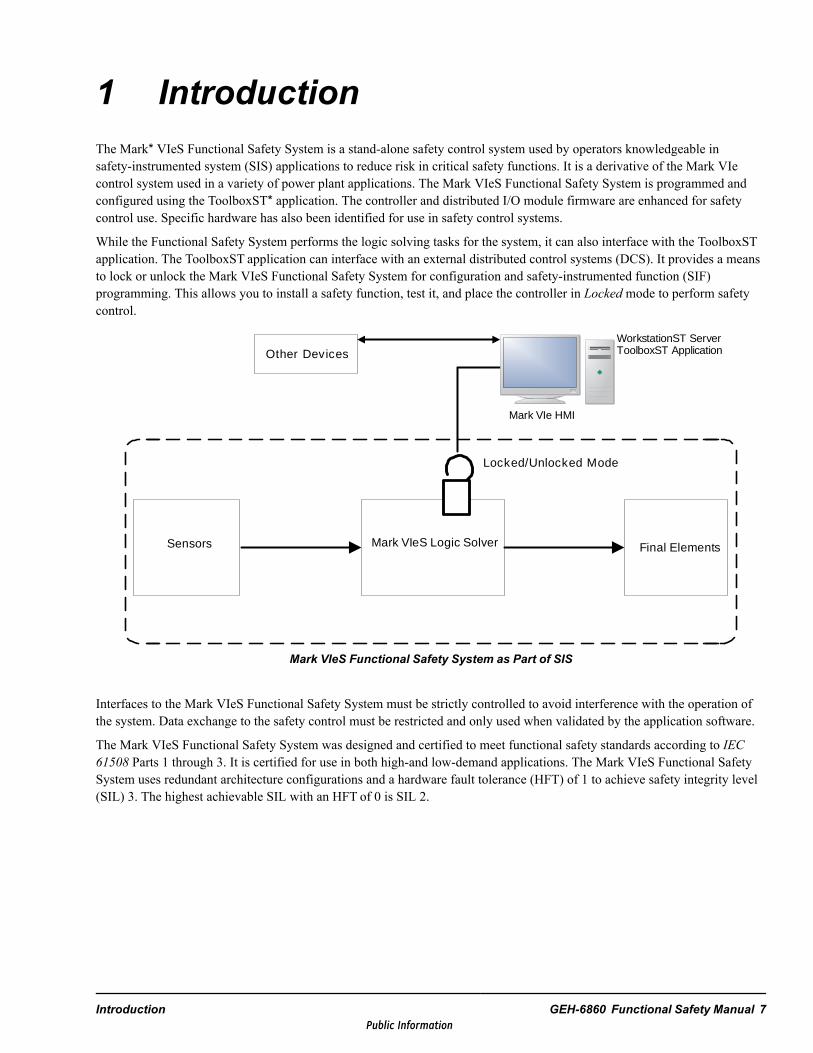
1 IntroductionThe Mark* VIeS Functional Safety System is a stand-alone safety control system used by operators knowledgeable insafety-instrumented system (SIS) applications to reduce risk in critical safety functions. It is a derivative of the Mark VIecontrol system used in a variety of power plant applications. The Mark VIeS Functional Safety System is programmed andconfigured using the ToolboxST* application. The controller and distributed I/O module firmware are enhanced for safetycontrol use. Specific hardware has also been identified for use in safety control systems.
While the Functional Safety System performs the logic solving tasks for the system, it can also interface with the ToolboxSTapplication. The ToolboxST application can interface with an external distributed control systems (DCS). It provides a meansto lock or unlock the Mark VIeS Functional Safety System for configuration and safety-instrumented function (SIF)programming. This allows you to install a safety function, test it, and place the controller in Locked mode to perform safetycontrol.
Sensors Mark VIeS Logic Solver Final Elements
Other DevicesWorkstationST ServerToolboxST Application
Locked/Unlocked Mode
Mark VIe HMI
Mark VIeS Functional Safety System as Part of SIS
Interfaces to the Mark VIeS Functional Safety System must be strictly controlled to avoid interference with the operation ofthe system. Data exchange to the safety control must be restricted and only used when validated by the application software.
The Mark VIeS Functional Safety System was designed and certified to meet functional safety standards according to IEC61508 Parts 1 through 3. It is certified for use in both high-and low-demand applications. The Mark VIeS Functional SafetySystem uses redundant architecture configurations and a hardware fault tolerance (HFT) of 1 to achieve safety integrity level(SIL) 3. The highest achievable SIL with an HFT of 0 is SIL 2.
Introduction GEH-6860 Functional Safety Manual 7Public Information
Attention
The information in this document applies to the overall Mark* VIe control system orMark VIeS Functional Safety System control products; however, your application maynot be licensed to access full system capability and I/O packs as described in thisdocument. For example, the Mark VIeS Functional Safety System for GeneralMarkets only utilizes the following I/O packs:
•• Analog I/O (YAIC)
•• Universal Analog (YUAA)
•• Vibration Input Monitor (YVIB)
•• Relay Output (YDOA)
•• Discrete Contact Input (YDIA)
•• Power Distribution System Diagnostics (PPDA)
•• Serial Modbus Communication (PSCA)
•• Mark VIeS Safety Controller (UCSCS2x)
•• Mark VIe Controller for Gateway (UCSCH1x)
8 GEH-6860 GEH-6860 MMark VIeS Control General Market Functional Safety ManualPublic Information
2 Functional SafetyIEC 61508-4 definitions are as follows:
Safety Freedom from unacceptable risk.
Risk Combination of the probability of occurrence of harm and the severity of that harm.
Functional Safety Part of the overall safety relating to the equipment under control (EUC) and the EUC control systemthat depends on the correct functioning of the Electrical/electronic/programmable electronic (E/E/PE) safety-related systems,other technology safety-related systems, and external risk reduction facilities.
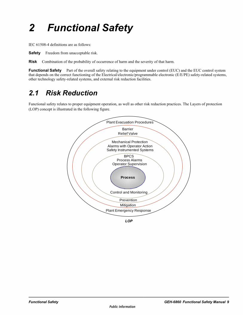
2.1 Risk ReductionFunctional safety relates to proper equipment operation, as well as other risk reduction practices. The Layers of protection(LOP) concept is illustrated in the following figure.
Control and Monitoring
PreventionMitigation
Plant Emergency Response
BPCSProcess Alarms
Operator Supervision
Mechanical ProtectionAlarms with Operator ActionSafety Instrumented Systems
Plant Evacuation Procedures
Relief ValveBarrier
Process
LOP
Functional Safety GEH-6860 Functional Safety Manual 9Public Information
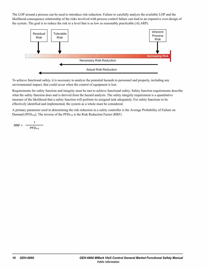
The LOP around a process can be used to introduce risk reduction. Failure to carefully analyze the available LOP and thelikelihood-consequence relationship of the risks involved with process control failure can lead to an expensive over-design ofthe system. The goal is to reduce the risk to a level that is as low as reasonably practicable (ALARP).
Residual
Risk
Tolerable
Risk
InherentProcess
Risk
Necessary Risk Reduction
Actual Risk Reduction
Increasing Risk
Residual Risk
Tolerable Risk
Inherent Process
Risk
Necessary Risk Reduction
Actual Risk Reduction
To achieve functional safety, it is necessary to analyze the potential hazards to personnel and property, including anyenvironmental impact, that could occur when the control of equipment is lost.
Requirements for safety function and integrity must be met to achieve functional safety. Safety function requirements describewhat the safety function does and is derived from the hazard analysis. The safety integrity requirement is a quantitativemeasure of the likelihood that a safety function will perform its assigned task adequately. For safety functions to beeffectively identified and implemented, the system as a whole must be considered.
A primary parameter used in determining the risk reduction in a safety controller is the Average Probability of Failure onDemand (PFDavg). The inverse of the PFDavg is the Risk Reduction Factor (RRF).
RRF =1
PFDavg
10 GEH-6860 GEH-6860 MMark VIeS Control General Market Functional Safety ManualPublic Information

2.2 Modes of OperationA demand mode is a mode operation in which the safety function is called upon only on demand. IEC 61508-4 clause 3.5.12defines two demand modes of operation:
• Low demand mode• High demand or continuous mode
Low demand describes the mode in which safety function demand occurs no greater than once per year and no greater thantwice the proof test frequency. In high demand mode, the frequency of demand is greater than once per year or greater thantwice the proof test frequency. Continuous mode is regarded as very high demand and is associated with the safety functionoperating to keep the EUC within its normal safe state.
The mode of operation is relevant when determining the target failure measure of a safety function. Low demand mode relatesto the PFDavg whereas high demand or continuous demand mode relates to measuring the probability of failure per hour(PFH) (there are approximately 104 hours in a year). IEC 61508 defines a scale of four distinct levels of risk reductionreferred to as the Safety Integrity Level (SIL).
SILs
SIL PFDavg Low Demand Mode PFH High Demand Mode RRF
1 ≥ 10-2 to < 10-1 ≥ 10-6 to < 10-5 > 10 to ≤ 100
2 ≥ 10-3 to < 10-2 ≥ 10-7 to < 10-6 > 100 to ≤ 1,000
3 ≥ 10-4 to < 10-3 ≥ 10-8 to < 10-7 > 1,000 to ≤ 10,000
4 ≥ 10-5 to < 10-4 ≥ 10-9 to < 10-8 > 10,000 to ≤ 100,000
The SIL applies to all elements in the safety loop (sensors, logic solver, and final element) and their architecture. The loopmust be considered in its entirety.
Sensor 1
Sensor 2
Mark VIeS Logic Solver
1 out of 2 1 out of 1
Valve 1
Valve 2
Safety Loop
2.3 Hazard and Risk AnalysisHazard and risk analyses determine the necessary safety functions and the required levels of risk reduction (refer to IEC61508-5:1998). The recommended safety life cycle stipulates the completion of a hazard and risk analysis early in theprocess.
A hazard analysis, the identification of potential sources of harm, determines the causes and consequences of hazardousevents. A team of professionals, familiar with both the EUC and safety-related systems, typically conducts the hazardanalysis.
A risk analysis is typically defined in three stages: hazard identification, hazard analysis, and risk assessment. Risk analysis,like hazard analysis, requires a large spectrum of expertise and a team effort is required to produce a viable result. Annexes A– F of IEC 61511-3 provides guidance in producing a risk analysis.
Functional Safety GEH-6860 Functional Safety Manual 11Public Information
2.4 Safety Life CycleThe safety life cycle is crucial to the philosophy of functional safety. The safety life cycle involves the followingrecommended stages:
1. Functional safety management including functional safety assessment
2. Safety life cycle structure and planning
3. Hazard and risk analysis
4. Allocation of safety functions to protection layers
5. Safety requirements specification for the safety control
6. Design and engineering of safety control
7. Design and development of other means of risk reduction
8. Installation, validation, and commissioning
9. Operation and maintenance
10. Modification and retrofit
11. Decommissioning
IEC 61511 defines how to use the safety life cycle to achieve the desired SIL. Although the safety life cycle is described hereand in IEC 61511 as a sequence of stages, in practice it is a repetitive process. If, for example, a modification is required inthe operational system, an impact analysis is required and the design changes should be reassessed starting with the hazardand risk analysis phase. Furthermore, for each safety function a hazard and risk analysis is required to define the safetyfunction requirements and required SIL.
2.5 Functional Safety ManagementFunctional safety must be managed during the entire time of the safety life cycle. IEC 61511 clause 5 describes the objectivesand requirements for the management of functional safety. The functional safety management plan should be a formaldocument that outlines the activities related to functional safety and the persons in the organization responsible for thoseactivities. It should also include functional safety assessment and audit planning.
IEC 61508 provides additional guidance about completing an effective functional safety management plan. The tables oftechnique and measures in Annex A and B of IEC 61508 Tab 1, 2, and 3 are particularly useful.
12 GEH-6860 GEH-6860 MMark VIeS Control General Market Functional Safety ManualPublic Information
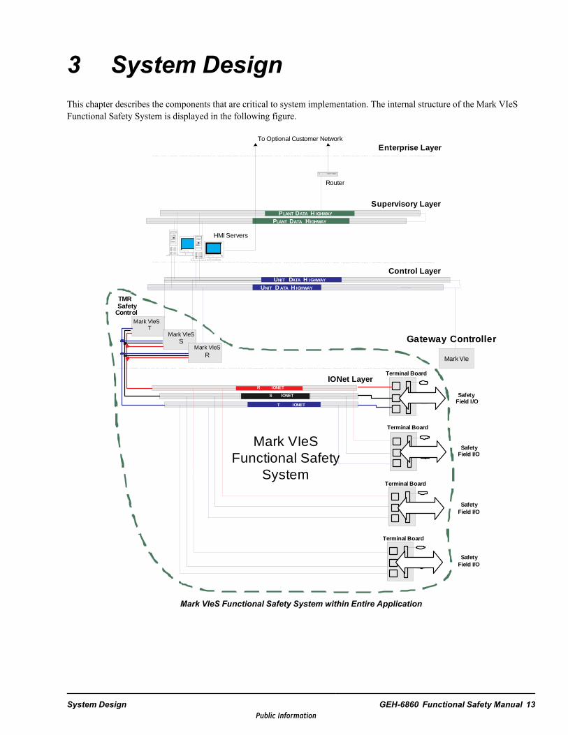
3 System DesignThis chapter describes the components that are critical to system implementation. The internal structure of the Mark VIeSFunctional Safety System is displayed in the following figure.
HMI Servers
Control Layer
Router
P P
To Optional Customer Network
Supervisory Layer
Mark VIeST
Mark VIeSS
Mark VIeSR
Enterprise Layer
Terminal Board
R IONET
S IONET
T IONET
IONet Layer
UNIT DATA IGHWAY H
Terminal Board
Terminal Board
Terminal Board
Mark VIe
SafetyControl
TMR
Mark VIeS Functional Safety
System
SafetyField I/O
SafetyField I/O
SafetyField I/O
SafetyField I/O
UNIT D ATA IGHWAYH
DATA IGHWAYH DATA IGHWAY HLANT
LANT
Gateway Control ler
Mark VIeS Functional Safety System within Entire Application
System Design GEH-6860 Functional Safety Manual 13Public Information
3.1 Primary Architecture ComponentsA Mark VIeS Functional Safety System for any supported architecture is built using a common set of safety approvedcomponents connected by a combination of direct wiring and the IONet communications bus. The Mark VIeS I/O signal pathconsists of three basic parts: terminal board, I/O pack, and IONet.
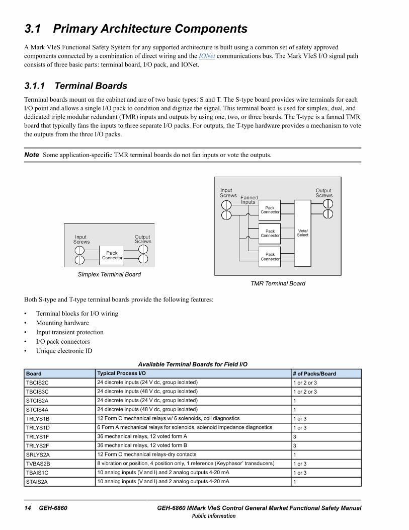
3.1.1 Terminal BoardsTerminal boards mount on the cabinet and are of two basic types: S and T. The S-type board provides wire terminals for eachI/O point and allows a single I/O pack to condition and digitize the signal. This terminal board is used for simplex, dual, anddedicated triple modular redundant (TMR) inputs and outputs by using one, two, or three boards. The T-type is a fanned TMRboard that typically fans the inputs to three separate I/O packs. For outputs, the T-type hardware provides a mechanism to votethe outputs from the three I/O packs.
Note Some application-specific TMR terminal boards do not fan inputs or vote the outputs.
Simplex Terminal BoardTMR Terminal Board
Both S-type and T-type terminal boards provide the following features:
• Terminal blocks for I/O wiring• Mounting hardware• Input transient protection• I/O pack connectors• Unique electronic ID
Available Terminal Boards for Field I/OBoard Typical Process I/O # of Packs/BoardTBCIS2C 24 discrete inputs (24 V dc, group isolated) 1 or 2 or 3TBCIS3C 24 discrete inputs (48 V dc, group isolated) 1 or 2 or 3STCIS2A 24 discrete inputs (24 V dc, group isolated) 1STCIS4A 24 discrete inputs (48 V dc, group isolated) 1TRLYS1B 12 Form C mechanical relays w/ 6 solenoids, coil diagnostics 1 or 3TRLYS1D 6 Form A mechanical relays for solenoids, solenoid impedance diagnostics 1 or 3TRLYS1F 36 mechanical relays, 12 voted form A 3TRLYS2F 36 mechanical relays, 12 voted form B 3SRLYS2A 12 Form C mechanical relays-dry contacts 1TVBAS2B 8 vibration or position, 4 position only, 1 reference (Keyphasor* transducers) 1 or 3TBAIS1C 10 analog inputs (V and I) and 2 analog outputs 4-20 mA 1 or 3STAIS2A 10 analog inputs (V and I) and 2 analog outputs 4-20 mA 1
14 GEH-6860 GEH-6860 MMark VIeS Control General Market Functional Safety ManualPublic Information

3.1.2 I/O PacksMark VIeS Functional Safety System I/O packs contain a common processor board and a data acquisition board that is uniqueto the type of device to which it is connected. I/O packs on each terminal board digitize signals, perform algorithms, andcommunicate with the controller. I/O packs provide fault detection through special circuitry in the data acquisition board andsoftware running in the CPU board. The fault status is transmitted to, and used by, the controllers. Each I/O pack transmitsinputs and receives outputs on both network interfaces if connected.
3.1.2.1 Process I/OTypical process inputs include contact, analog, and thermocouple signals. Typical process outputs include relays and analogoutputs. All typical process outputs based on inputs are processed by the system controller. The following process I/O packsare available for use in the Mark VIeS Functional Safety System:
Process I/O Packs
I/O PackAssociatedTerminal Board(s) Functions Redundancy
IS420YAICS1B TBAISIC, STAIS2A10 analog inputs (voltage, 4-20 mA)2 analog outputs (4-20 mA)
1 or 3 packs
IS420YDIAS1BTBCIS2C, TBCIS3C,STCIS2A
24 discrete inputs w/ group isolation(24 V dc, 48 V dc, or 125 V dc)
1, 2, or 3 packs
IS420YDOAS1BTRLYS1B, TRLYS1D,TRLYS1F, TRLYS2F,SRLYS2A
12 relay outputs6 relay outputs
1 or 3 packs
IS420YVIBS1B TVBAS2B 8 vibration, 3 position only, 2 position or Keyphasor 1 or 3 packs
3.1.3 IONetThe controllers and I/O packs communicate through the internal IONet (a closed network), using a proprietary IONetprotocol. IONet communications are as follows:
• I/O packs that multicast inputs to the controllers each frame• Controllers that broadcast outputs to the I/O packs each frame
System Design GEH-6860 Functional Safety Manual 15Public Information

3.2 Safety-instrumented Functions (SIF)Safety-intsrumented Function (SIF) configurations are created and maintained in the ToolboxST application, along with thebasic process control configurations. This environment provides all the facilities to create, download, and maintain theseconfigurations.
Safety controllers have two operating modes for application execution. When in Unlocked mode, full access to the controlleris granted, including the ability to download code, set constants, force points, and all other configuration and diagnosticoperations. When in Locked mode, all changes to the controller operation are prevented to ensure the integrity of the safetyfunctions.
Within the Safety controller, branding is used to support Locked mode and integrity checks. When the controller is unlockedand the operator is satisfied with the system operation, the system configuration is branded so that it can be uniquelyidentified. Once branded, a diagnostic alarm is generated if there are any changes to application code, constants, hardwareintegrity, or network connectivity. The diagnostics based on branding include all communications through the IONet toprovide 100% network diagnostic coverage (DC) independent of the network hardware selected.
The typical sequence of application creation includes:
• Application development• Hardware connection and configuration• Function testing while unlocked• Application branding (after being tested and proven)• Placing the controller in Locked mode
16 GEH-6860 GEH-6860 MMark VIeS Control General Market Functional Safety ManualPublic Information
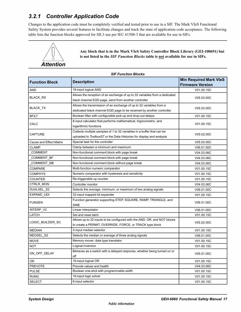
3.2.1 Controller Application CodeChanges to the application code must be completely verified and tested prior to use in a SIF. The Mark VIeS FunctionalSafety System provides several features to facilitate changes and track the state of application code acceptance. The followingtable lists the function blocks approved for SIL3 use per IEC 61508-3 that are available for use in SIFs.
Attention
Any block that is in the Mark VIeS Safety Controller Block Library (GEI-100691) butis not listed in the SIF Function Blocks table is not available for use in SIFs.
SIF Function Blocks
Function Block Description Min Required Mark VIeSFirmware Version
AND 16-input logical AND V01.00.15C
BLACK_RXAllows the reception of an exchange of up to 32 variables from a dedicatedblack channel EGD page, send from another controller
V05.03.00C
BLACK_TXAllows the transmission of an exchange of up to 32 variables from adedicated black channel EGD page to be received by another controller
V05.03.00C
BFILT Boolean filter with configurable pick-up and drop-out delays V01.00.15C
CALC8-input calculator that performs mathematical, trigonometric, andlogarithmic functions
V01.00.15C
CAPTURECollects multiple samples of 1 to 32 variables in a buffer that can beuploaded to ToolboxSTor the Data Historian for display and analysis
V05.02.00C
Cause and Effect Matrix Special task for the controller V05.03.00CCLAMP Clamp between a minimum and maximum V06.01.00C_COMMENT Non-functional comment block with page break V04.03.06C_COMMENT_BF Non-functional comment block with page break V04.03.06C_COMMENT_NB Non-functional comment block without page break V04.03.06CCOMPARE Multi-function numeric comparator V01.00.15CCOMPHYS Numeric comparator with hysteresis and sensitivity V01.00.15CCOUNTER Re-triggerable up counter V01.00.15CCTRLR_MON Controller monitor V04.03.06CDUALSEL_S2 Selects the average, minimum, or maximum of two analog signals V06.01.00CEXPAND_UDI 32-input mapped bit expander V01.00.15C
FUNGENFunction generator supporting STEP, SQUARE, RAMP, TRIANGLE, andSINE
V06.01.00C
INTERP_V2 Linear interpolator V06.01.00CLATCH Set and reset latch V01.00.15C
LOGIC_BUILDER_SCAllows up to 32 inputs to be configured with the AND, OR, and NOT blocksto create a PERMIT, OVERRIDE, FORCE, or TRACK type block
V05.02.00C
MEDIAN 3-input median selector V01.00.15CMEDSEL_S2 Selects the median or average of three analog signals V06.01.00CMOVE Memory mover; data type translator V01.00.15CNOT Logical inversion V01.00.15C
ON_OFF_DELAYBehaves as a switch with a delayed response, whether being turned on oroff
V05.01.00C
OR 16-input logical OR V01.00.15CPREVOTE Prevote values and health V04.03.06CPULSE Boolean one-shot with programmable width V01.00.15CRUNG 16-input logic solver V01.00.15CSELECT 8-input selector V01.00.15C
System Design GEH-6860 Functional Safety Manual 17Public Information

SIF Function Blocks (continued)
Function Block Description Min Required Mark VIeSFirmware Version
SYS_OUTPUTS I/O system command output interface V01.00.15CTEMP_STATUS Temperature sensing V01.00.15CTIMER Re-triggerable up-count timer V01.00.15CTIMER_V2 Accumulates incremental time into CURTIME while RUN is True V05.01.00CUNIT_DELAY One frame delay line V01.00.15CVAR_HEALTH Variable health status V01.00.15CVOTE M-out-of-N voter V06.01.00C
3.2.1.1 Variable HealthInside the Mark VIeS Functional Safety System controller, every variable is associated with a set of qualities that provideadditional information, or support advanced features such as forcing, simulation, or alarms. Some of these qualities are visibleto users through ToolboxST application, and others are made available to application code through blockware.
Variable health measures the validity of the data stored in the variable. When the ToolboxST application collects variable datafrom the controller, it also scans the health information and displays a U (for Unhealthy) beside each live data value if thecorresponding health quality is FALSE. The Variable Health block (VAR_HEALTH) allows application code to accessvariable health. The Prevote block (PREVOTE) allows application code to access prevote values and health.
The health of a variable with no connection to I/O is always TRUE, and therefore uninteresting. Also, output health is alwaysTRUE. The health of variables associated with I/O is calculated from point and link health. Point health originates fromsoftware close to the hardware. Link health is calculated by the controller. These two values are passed through a logical ANDgate to form variable health.
Each I/O server defines the non user-configurable point and group health. For example, the point health of an analog inputmay be declared unhealthy if its value exceeds some limit, and the point health of all inputs on an I/O pack may be declaredunhealthy if a problem is detected in the signal acquisition hardware. It may not be practical for an I/O server to provide ahealth indication for each individual point and so this component of variable health is optional.
In a Mark VIeS Functional Safety System, I/O is typically distributed at the I/O packs or across another network such as theUnit Data Highway (UDH). As such, the controller provides link health by validating that all transport layer checks betweenthe I/O server and the controller are met. These may include timely delivery, signature matching, and checksums.
Redundant I/O features complicate the explanation of the variable health calculation. ATMR input module supplies threeopinions of variable health to the controller. Since these inputs are voted, as long as two out of three are healthy, the resultingvariable is also healthy.
A dual input module (either simplex I/O pack, dual network; or dual I/O pack, single network) provides two opinions ofvariable health to the controller. Since the controller cannot vote two opinions, it uses link health to select one of the channelsand incorporates only the selected channel's point and group information into the variable health calculation. If the link healthon the selected channel ever becomes unhealthy, the controller immediately switches to the second channel.
The VAR_HEALTH block reveals the variable health and the link health of the connected variable. Application developerscan choose to monitor the health of individual variables or the health of the network (link) that supplies many variables,especially if the I/O on the other end of that network does not provide any additional health information. For TMR inputs, thelink health pin provides a voted link health (that is, two out of three channels). For dual inputs, the link health pin provides thehealth of the selected channel.
18 GEH-6860 GEH-6860 MMark VIeS Control General Market Functional Safety ManualPublic Information

The following ToolboxST screen displays a TMRYDIAwith two faulted channels. Because of the faults, all points on theYDIA are marked as Unhealthy.
The current value and health of variables connected to YDIA inputs are displayed. U indicates an unhealthy value.
From the PreVote tab, the T channel is healthy but the R and S channels are not, due to loss of communication.
Variable Health Example
System Design GEH-6860 Functional Safety Manual 19Public Information

The following ToolboxST screen displays a VAR_HEALTH block. Both variables are connected to the faulted YDOA. Sincethe cause of the fault is communication, both the HEALTH1 and LINKOK1 output pins are False.
Block outputs can be used to drive alarms or initiate protective actions.
VAR_Health Block Outputs
3.2.1.2 Temperature MonitorThere are two application code blocks available for monitoring the safety controller’s temperature: TEMP_STATUS andCTRLR_MON. These controller application code blocks can be used to set alarms, actuate fans, or perform other actionsappropriate for the specific environment in which the control cabinet is placed.
3.2.1.3 Disabling TransmittersThe DUALSEL_S2 and MEDSEL_S2 application blocks support the disabling of transmitters both automatically andmanually. When the quality status of transmitter A is BAD, transmitter A is automatically disabled. Once the quality status oftransmitter A becomes GOOD and the value of input A is within the deviation limits set by the user, transmitter A isautomatically enabled. This concept also applies to input B (and input C on MEDSEL_S2).
The control word input (refer to the following Attention statement) is used by the HMI operator for manual control. Themanual commands from the HMI allow each input to be enabled or disabled. A manually disabled transmitter can bemanually enabled, regardless of its deviation status. If all input transmitters are enabled and have a GOOD quality status andA is manually disabled, then A is disabled. This concept also applies to input B (and input C on MEDSEL_S2).
In the MEDSEL_S2 block, if one transmitter is already disabled for any reason, a second transmitter may be disabled if theblock is configured to allow one transmitter operation.
Attention
Operation of the control word input in the Mark VIeS Functional Safety Systemdiffers from that in other Mark VIe control products. In the Mark VIeS FunctionalSafety System, the variable attached to the control word input must be driven from aconsumed EGD page. The EGD producer device driving the variable must implementthe necessary push-button reset logic to clear the command after 1 second.
20 GEH-6860 GEH-6860 MMark VIeS Control General Market Functional Safety ManualPublic Information
Note Refer to theMark VIeS Safety Controller Block Library (GEI-100691) for a full explanation of DUALSEL_S2 andMEDSEL_S2 block functionality.
Commands are only accepted by the block if a transition from NO_CMD to a command value is detected while the CTL_EXT input is healthy. After a command is accepted by the block, the CTL_EXT pin is ignored for a period of two secondsafter which a valid transition from NO_CMD must be detected to accept another command.
Example Configuration:
An HMI faceplate is created to display data from the DUALSEL_S2 block from a Mark VIeS Functional Safety System.EGD signals are consumed by the HMI from the Mark VIeS Functional Safety System and are used to drive the faceplate.Unlike in the Mark VIe control, the control word variable from the Mark VIeS Functional Safety System is read-only and isused to show feedback status. The control word command is written to a separate EGD signal driven from a Mark VIedevice. For example, after adding the DUALSEL_S2 block to the Mark VIeS Functional Safety System and attaching theEGD signals to the faceplate, the following is required:
In a Mark VIe device:• Create a control word variable (data type UINT).• Add the control word variable to a produced EGD page.• Add push-button reset logic in the blockware to reset the control word value to NO_CMD (0). The control word should
be reset after one second of it being non-zero.
In the HMI:• Attach the control word variable from the Functional Safety System to the control word logic in the appropriate
DUALSEL_S2 faceplate.
In the Mark VIeS device:• Attach the control word variable from the Functional Safety System to the CTL_EXT pin of the appropriate
DUALSEL_S2 block.
System Design GEH-6860 Functional Safety Manual 21Public Information

3.2.2 Locked ModeThe Mark VIeS Functional Safety System provides a level of protection (LOP) against accidental modification of the safetysoftware through Locked mode. In general, all functions or features that have the potential to modify the controller aredisabled when in locked mode, for example:
• Variable and constant modification• Variable forcing• Application code download• Firmware download• Restart commands from ToolboxST application• External file writes to flash memory• Low-level diagnostic commands• Time set commands
The controller starts in Locked mode and remains there until an Unlock command is received from the ToolboxST application.When the controller receives a Lock command from the ToolboxST application or the controller is restarted, it returns toLocked mode. When the controller is unlocked, it generates a diagnostic alarm to log the event. The controller tracks its lockstate through a configuration variable (for example, Is_Locked_R), viewable through the application code, so that appropriatecontrol action can be taken or an external contact can be driven, if desired.
To lock the controllers
1. From the Component Editor toolbar, click the key icon. The Lock / Unlock dialog box displays.
2. Click the Lock All button and the controller status displays as Locked.
22 GEH-6860 GEH-6860 MMark VIeS Control General Market Functional Safety ManualPublic Information
3.2.3 Unlocked Mode
Warning
While in Unlockedmode, the Mark VIeS is not inherently less safe than when inLocked mode, as SIF implementation is the same. However, when unlocked, thecontroller could become unsafe, as it is open to modifications that could lead to anunsafe condition.
The Mark VIeS allows online application code changes in Unlocked mode. Take every precaution to ensure that any onlinechange to application code does not cause an unintended error during the download. This is particularly relevant for dualnetwork configurations in which separate I/O packs are driven by either redundant controller.
The application code does not normally allow safety loops to be activated in Unlocked mode. To test a loop in Unlockedmode, the permissives preventing operation must be temporarily forced out.
When online repair is required on an operating, redundant system, it is not necessary to unlock the control system todownload software. Non-configured I/O packs and controllers boot into Unlocked mode, allowing them to receive the initialsoftware download. The lock status of all the components can be determined by running a download scan.
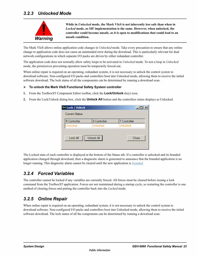
To unlock the Mark VIeS Functional Safety System controller
1. From the ToolboxST Component Editor toolbar, click the Lock/Unlock (key) icon.
2. From the Lock/Unlock dialog box, click the Unlock All button and the controllers status displays as Unlocked.
The Locked state of each controller is displayed at the bottom of the Status tab. If a controller is unlocked and its brandedapplication changed through download, then a diagnostic alarm is generated to announce that the branded application is nolonger running. This diagnostic alarm cannot be cleared until the new application is branded.
3.2.4 Forced VariablesThe controller cannot be locked if any variables are currently forced. All forces must be cleared before issuing a lockcommand from the ToolboxST application. Forces are not maintained during a startup cycle, so restarting the controller is onemethod of clearing forces and putting the controller back into the Locked mode.
3.2.5 Online RepairWhen online repair is required on an operating, redundant system, it is not necessary to unlock the control system todownload software. Non-configured I/O packs and controllers boot into Unlocked mode, allowing them to receive the initialsoftware download. The lock status of all the components can be determined by running a download scan.
System Design GEH-6860 Functional Safety Manual 23Public Information
3.2.6 BrandingApplication code and configuration that is part of a SIF must be certified per IEC 61511 prior to use. To facilitate this activity,the controller allows the user to designate a particular set of code as acceptable for its intended purpose. In the ToolboxSTapplication, this process is called branding. Branding is also required after upgrades from BPPB to BPPC based Safety I/Opacks.
When the code is branded, the controller calculates a checksum of all application code and configuration information, andretains it in nonvolatile memory. Whenever the application code or I/O pack configuration is modified, the controller detectsthe difference and generates a diagnostic alarm. Similarly, until the application code has been initially branded, a diagnosticalarm will be active noting the fact.
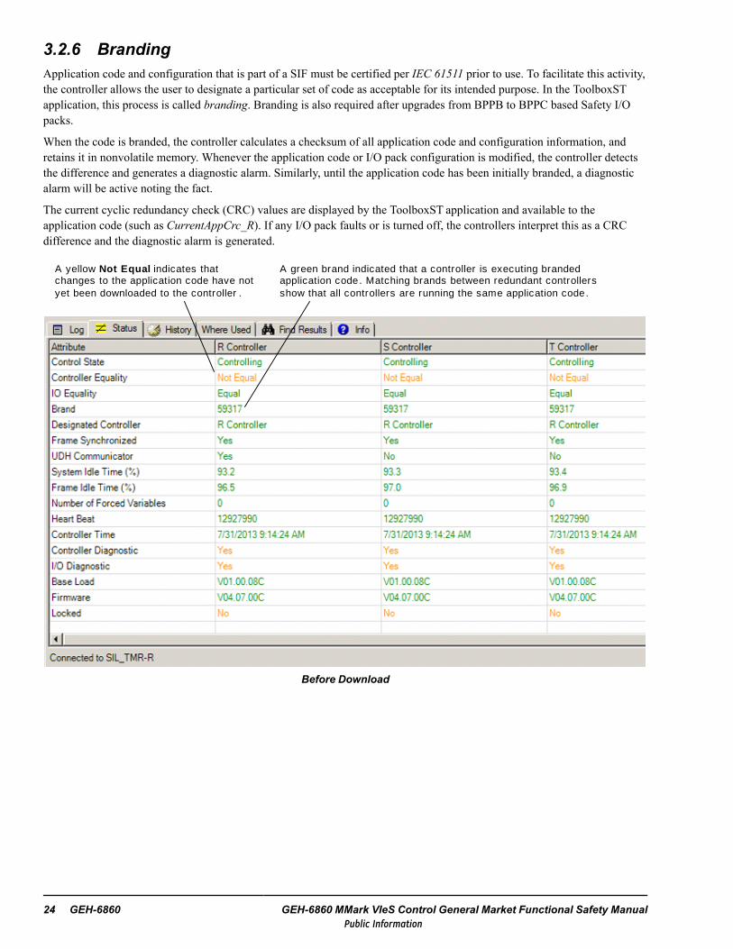
The current cyclic redundancy check (CRC) values are displayed by the ToolboxST application and available to theapplication code (such as CurrentAppCrc_R). If any I/O pack faults or is turned off, the controllers interpret this as a CRCdifference and the diagnostic alarm is generated.
A yellow Not Equal indicates that changes to the application code have not yet been downloaded to the controller .
A green brand indicated that a controller is executing branded application code. Matching brands between redundant controllers show that all controllers are running the same application code.
Before Download
24 GEH-6860 GEH-6860 MMark VIeS Control General Market Functional Safety ManualPublic Information

After download but before branding, the following Status displays.
A yellow brand indicates that the application currently running in the controller does not match the previous brand and needs to be certified and branded prior to use in a SIF.
Note To download an application code change, the controllers must be unlocked.
System Design GEH-6860 Functional Safety Manual 25Public Information

To brand the controller’s application and configuration: from the ToolboxST Component Editor toolbar,click the Brand icon.
After branding, the text turns green and all three controllers match. The controllers are also locked to prevent further changes.
Branded and Locked
3.2.7 Startup Shutdown ProcessThe safety control system can shut down either by manual operator action or automatically as a result of certain detected faultconditions. A number of protective features are included in the Mark VIeS Functional Safety System to ensure that a SIF isnot compromised by inadvertent modifications made to the system. These features include an operating Locked mode, whichprevents unwanted changes, and application code branding, which detects configuration changes.
3.2.7.1 Manual ShutdownA manual shutdown occurs when the controller power supply is manually turned off. When power is reapplied, the controllerproceeds through control startup states that are designed to synchronize its application states with the other redundantcontrollers. Forced values are not retained through a power down cycle. If forced values exist and only one controller of aredundant set is restarted, forcing will be restored and the restarted controller will obtain those forced values from thedesignated controller during the Data Initialization control state. The restarted controller enters the same locked state as thedesignated controller.
26 GEH-6860 GEH-6860 MMark VIeS Control General Market Functional Safety ManualPublic Information
3.2.7.2 Fault Detected ShutdownWhen fault conditions are detected, the Safety controller either restarts or enters a fail-safe control state, depending on thetype of fault condition. In the event of a processor restart, the I/O packs are programmed to operate in their fail-safe state.
The controller restarts on three conditions:
• Software watchdog timeout• Hardware watchdog timeout• Operating system process control failure
The watchdog timer functions are generally meant to ensure safe controller operation in conditions where one or moreruntime processes are overloaded. Each periodic safety-critical process initializes and then continually tickles one or moresoftware watchdog timers, which are implemented by the system firmware process and configured with expected tickle rates.If a watchdog timer is tickled too quickly, too slowly, or not at all, the system process restarts the controller.
When using a hardware watchdog timer, a backup watchdog process is also implemented. If this process fails to tickle thehardware watchdog timer quickly enough, the board restarts.
In addition to watchdog timeouts, a process control failure in the operating system can cause an automatic restart. If anyruntime process, other than the system process, fails to run due to a problem, the operating system prompts the system processto restart the controller. If the system process fails, the hardware watchdog process detects the failure of the softwarewatchdog function and forces a restart by not tickling the hardware watchdog timer.
A different set of fault conditions cause the controller to enter its fail-safe control state, instead of restarting the controller. Inthis state, the controller outputs to the I/O packs are disabled, forcing the I/O packs, in turn, to enter their fail-safe state. Inthis state, I/O packs drive their physical outputs to safe values as configured.
In the controller, the sequencer process continuously conducts the following program flow integrity malfunction tests:
• Critical process order of execution• Critical process scheduling overrun and under-run• Frame period• Frame state timeout intervals• Frame number
If any of these tests fail three consecutive times (generally three frames), appropriate diagnostic alarms are generated. Afterfive successive failures, the system is placed in the fail-safe control state.
System Design GEH-6860 Functional Safety Manual 27Public Information

3.3 Online SIFsThe Functional Safety System components used by the online SIFs and their interconnections in TMR architecture aredisplayed in the following figure.
TMR Safety Controllers
IONet LayerYDIA Discrete Inputs
YDOA Discrete Outputs
YAIC Analog I/O
R IONet
S IONet
R IONet
Controller and I/O – TMR Control Mode
The figure also illustrates the top-level architecture for SIL 3 capability, using a TMR, 2 out of 3, safety architecture. Thisdeployment architecture is referred to in Mark VIeS documentation as the TMR Control Mode.
28 GEH-6860 GEH-6860 MMark VIeS Control General Market Functional Safety ManualPublic Information

3.4 RedundancyThe Mark VIeS Functional Safety System can be set up in various traditional safety architectures that allow selections amongSIL capability, availability, and cost to better serve the specific needs of an application. TMR, dual, and simplex controlmodes are supported.
The controllers are designated as R, S, and T in a TMR system, R and S in a dual system, and R in a simplex system. Eachcontroller owns one IONet. The R controller sends outputs to an I/O module through the R IONet, the S controller sendsoutputs through the S IONet, and the T controller sends outputs through the T IONet.
IONet features include:
• Ethernet User Datagram Protocol (UDP) using Dynamic Host Configuration Protocol (DHCP) for network addressassignments. While based on Ethernet hardware and protocol standards, the IONet is maintained as a separate physicalnetwork to avoid risks of interference from other network traffic.
• Full duplex Ethernet switches throughout, so no message collisions impact system timing• IEEE® 1588 protocol through the R, S, and T IONets to synchronize the clock of the I/O modules and controllers to
within ±100 microseconds• Coordination of IONet traffic and controller action to ensure minimum predictable latency for inputs (given IEEE 1588
timing alignment). Controller outputs take place at the same time and all output I/O packs exhibit consistent latency inprocessing and updating the outputs.
3.4.1 TMR Control ModeIn the TMR control mode, three independent controllers communicate with the I/O through three independent IONetchannels. The TMR control mode with a hardware fault tolerance (HFT) of 1 is designed for SIL 3 capability with the runningreliability of 2 out of 3 redundancy. Each independent controller receives three independent sets of input data, one from eachIONet for 2 out of 3 input voting. Controller outputs are 2 out of 3 voted in the output circuitry. TMR control mode functionsare as follows:
• TMR (2 out of 3): SIL 3 high and low demand for de-energize-to-trip applications• TMR (2 out of 3): SIL 2 low demand for energize-to-trip applications• Degraded TMR (1 out of 2): SIL 3 high and low demand for de-energize-to-trip applications• TMR degradation sequence: (2 out of 3) → (1 out of 2) → Fail Safe
System Design GEH-6860 Functional Safety Manual 29Public Information

TMR Fanned InputSingle discrete/analog sensor is fanned through a common terminal board to three independent input packs, 2oo3 voting is done in the controller set.
TMR Dedicat ed InputThree redundant discrete/analog sensors are wired to three independent input modules, 2oo3 voting is done in the controller set.
Sensor A
Sensor A1
Sensor A2
Sensor A3 Actuator
TMR Out put s Vot ed on Terminal BoardThe three packs receive output commands from their associated controller, the common terminal board then performs 2oo3 voting on the outputs and controls the discrete actuator.
2oo3 Voting in Actuator
TMR Out put s Voted in Act uatorThree independent output modules receive the output command from their associated controller, then command the actuator, 2oo3 voting performed in the actuator.
TMR Cont ro l lersThree Mark VIeS controllers work as a set synchronizing data every frame (sweep). Each controller receives inputs on all 3 I/O networks, and sends output commands on designated I/O network.
TMR I/O Net workEthernet based TMR I/O network supports both centralized and distributed I/O modules.
R S T
Embedded Cont ro l ler Gat ewayEmbedded controller for communication interface, options:- OPC-UA server- Modbus slave
Third Party Control System
PC Based GatewayPC based communication interface, options :- OPC-DA server- OPC-UA server- Modbus master
When TMR controllers are present in a system, dual and simplex inputs and simplex outputs, in addition to TMR I/O pack,can be used. This allows for a mix of redundancy within a single system. Some I/O packs can be TMR to support SIL 3 forcritical safety functions, while other I/O packs can use less hardware and support a lower SIL for less critical functions.
30 GEH-6860 GEH-6860 MMark VIeS Control General Market Functional Safety ManualPublic Information

TMR redundancy for I/O packs can be either dedicated (each mounted to individual S-type terminal boards) or TMR fanned(each mounted to a single T-type terminal board). With TMR, each I/O pack for field input and output is uniquely associatedwith only one IONet.
With TMR fanned I/O, each input point is read by three independent I/O packs that receive the actual field input through acommon terminal board that fans the input to each of the three I/O packs. Each I/O pack receives output messages from itsown controller. The three independent I/O pack outputs are then 2 out of 3 hardware voted on a common terminal board.
TMR Fanned Mode with Three I/O Packs and One T-type Terminal Board
With TMR dedicated, the outputs or inputs for each I/O pack can be connected to an independent terminal board, allowing the2 out of 3 voting to be performed in the field output devices outside the Mark VIeS Functional Safety System.
Dedicated Mode with Three I/O Packs and three S-type Terminal Boards
System Design GEH-6860 Functional Safety Manual 31Public Information

3.4.2 Dual Control ModeThe dual control mode contains two controllers, two IONets, and either a single I/O pack or fanned TMR I/O packs. In a dualsystem, the level of I/O reliability can be varied to meet the application needs for specific I/O packs.
Dual control mode functions are as follows:
• Dual (1 out of 2): SIL 3 high and low demand for de-energize-to-trip applications.• Dual (2 out of 2): SIL 2 low demand for energize and de-energize-to-trip applications
TMR Fanned InputSingle sensor is fanned through a common terminal board to three independent input packs, 2oo3 voting done in the controller set.
Single SensorSingle sensor wired to a single input module with dual I/O network to controller set.
Sensor A
Sensor A
Sensor A1
Sensor A2
Actuator
TMR Outputs Vot ed on Terminal BoardThe three output packs receive an output command from designated controller, the common terminal board then performs 2oo3 voting and controls the actuator.
Acutator
1oo2 De-energ ize t o Trip in Output ModulesTwo independent output modules receive the output command from designated controller, combination of two creates 1oo2 de-energize to tr ip function across the two modules.
Dual Cont ro l lersDual Mark VIeS controllers work as a controller set synchronizing data every frame (sweep). Each controller receives inputs on both I/O networks, and sends output commands on designated I/O network.
Dual I/O Net workEthernet based dual I/O network supports both centralized and distributed I/O modules.
Dual SensorDual sensors wired to independent input modules with independent I/O networks to controller set.
Third Party Control System
R S
PC Based GatewayPC based communication interface, options:- OPC-DA server- OPC-UA server- Modbus master
Embedded Cont ro l ler Gat ewayEmbedded controller for communication interface, options:- OPC-UA server- Modbus slave
In a dual Mark VIeS Functional Safety System, both controllers receive inputs from the I/O packs on both networks andcontinuously transmit outputs on their respective IONet. Since redundant data is transmitted continuously from the I/O packand controller, both the pack and controller must select which network to use.
32 GEH-6860 GEH-6860 MMark VIeS Control General Market Functional Safety ManualPublic Information

At power up, the controller or I/O pack listens for data on both networks. The channel that delivers the first valid packetbecomes the preferred network. The I/O pack or controller uses this data as long as the data continues to arrive on thatchannel. If the preferred channel does not deliver the data in a frame, the other channel becomes the preferred channel if itsupplies valid data. This prevents a given I/O pack/controller from bouncing back and forth between two sources of data. As aresult, different I/O packs/controllers may have separate preferred data sources, but this can also happen if a component fails.
3.4.2.1 Single I/O Pack Dual Network I/O ModuleThe I/O option A is a single I/O pack dual network I/O module setup. This configuration is typically used for single sensorI/O. A single sensor connects to a single set of acquisition electronics but connects to two networks.
Dual Mode with One I/O Pack and Two IONets
The I/O pack delivers input data on both networks at the beginning of the frame and receives output data from bothcontrollers at the end of the frame. The reliability and availability features include:
• HFT 0• Single data acquisition• Redundant network
3.4.2.2 Dual Single I/O Pack Single Network I/O ModuleThe I/O option B is two single pack, single network I/O modules. This configuration is typically used for inputs that havemultiple sensors monitoring the same process points. Two sensors are connected to two independent I/O modules.
Dual Mode with Two Single Pack, Single IONet Modules
Each I/O pack delivers input data on a separate network at the beginning of the frame and receives output data from separatecontrollers at the end of the frame. The reliability and availability features include:
• HFT 1• Redundant sensors• Redundant data acquisition• Redundant network• Online repair
System Design GEH-6860 Functional Safety Manual 33Public Information
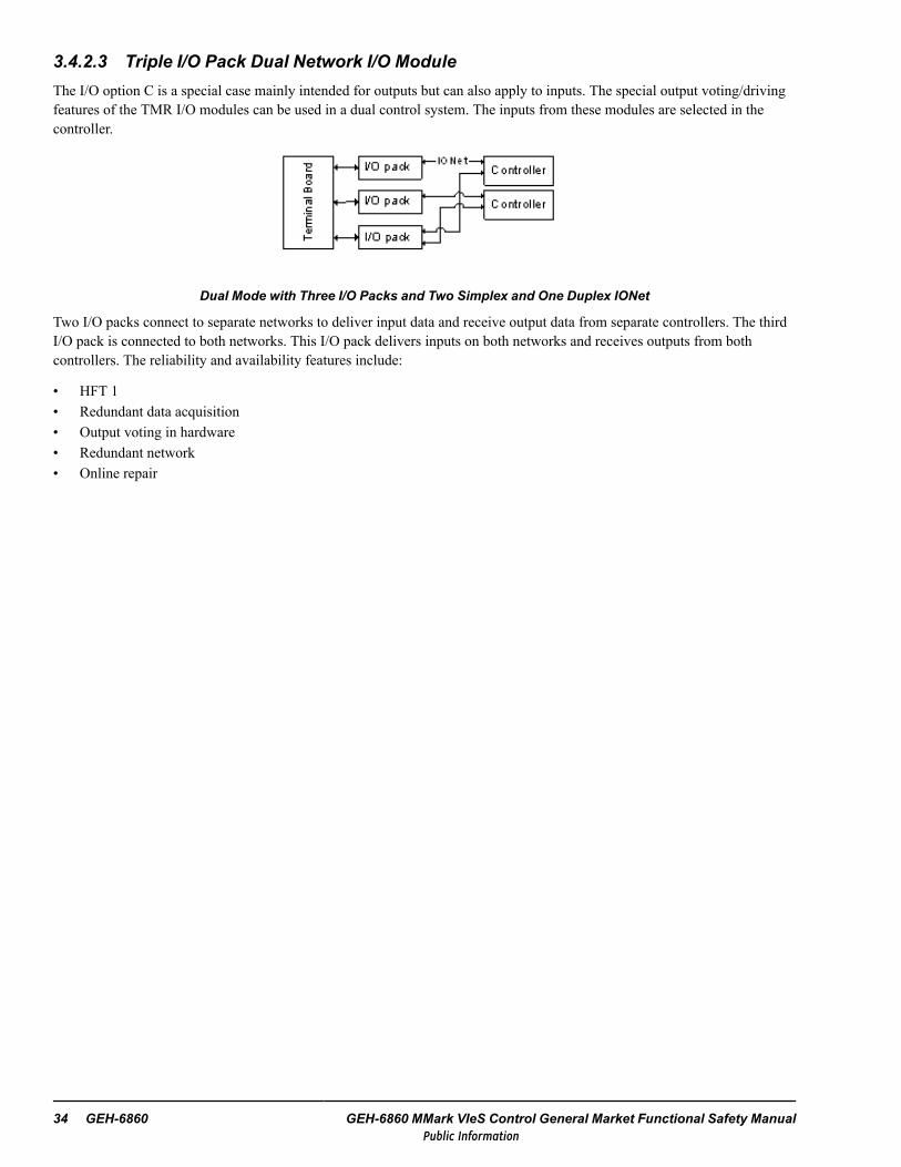
3.4.2.3 Triple I/O Pack Dual Network I/O ModuleThe I/O option C is a special case mainly intended for outputs but can also apply to inputs. The special output voting/drivingfeatures of the TMR I/O modules can be used in a dual control system. The inputs from these modules are selected in thecontroller.
Dual Mode with Three I/O Packs and Two Simplex and One Duplex IONet
Two I/O packs connect to separate networks to deliver input data and receive output data from separate controllers. The thirdI/O pack is connected to both networks. This I/O pack delivers inputs on both networks and receives outputs from bothcontrollers. The reliability and availability features include:
• HFT 1• Redundant data acquisition• Output voting in hardware• Redundant network• Online repair
34 GEH-6860 GEH-6860 MMark VIeS Control General Market Functional Safety ManualPublic Information

3.4.3 Simplex Control Mode, 1 out of 1Simplex (1 out of 1) control mode is SIL 2 low demand capable for de-energize-to-trip and SIL 1 for vibration applications.Each I/O pack delivers an input packet at the beginning of the frame on its primary network. The controller sees the inputsfrom all I/O packs, runs application code, and delivers a broadcast output packet(s) that contains the outputs for all I/Omodules.
R
Simplex Cont ro l lerSimplex Mark VIeS controller receives inputs and sends outputs on the one I/O network.
I/O Net workEthernet based I/O network supports both centralized and distributed I/O modules.
PC Based Gat ewayPC based communication interface, options:- OPC-DA server- OPC-UA server- Modbus master
Third Party Control System
Embedded Cont ro l ler Gat ewayEmbedded controller for communication interface, options:- OPC-UA server- Modbus slave
Sing le SensorSingle sensor wired to a single input module with a simplex I/O network to controller.
Sensor A
Sensor A1
Sensor A2
Dual SensorDual sensors wired to independent input modules with a simplex I/O network to controller.
Actuator
Simplex OutputOne output pack receives an output command from the controller.
System Design GEH-6860 Functional Safety Manual 35Public Information
3.5 Control and Protection
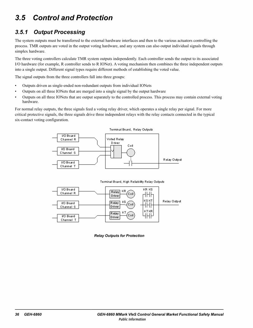
3.5.1 Output ProcessingThe system outputs must be transferred to the external hardware interfaces and then to the various actuators controlling theprocess. TMR outputs are voted in the output voting hardware, and any system can also output individual signals throughsimplex hardware.
The three voting controllers calculate TMR system outputs independently. Each controller sends the output to its associatedI/O hardware (for example, R controller sends to R IONet). A voting mechanism then combines the three independent outputsinto a single output. Different signal types require different methods of establishing the voted value.
The signal outputs from the three controllers fall into three groups:
• Outputs driven as single-ended non-redundant outputs from individual IONets• Outputs on all three IONets that are merged into a single signal by the output hardware• Outputs on all three IONets that are output separately to the controlled process. This process may contain external voting
hardware.
For normal relay outputs, the three signals feed a voting relay driver, which operates a single relay per signal. For morecritical protective signals, the three signals drive three independent relays with the relay contacts connected in the typicalsix-contact voting configuration.
Relay Outputs for Protection
36 GEH-6860 GEH-6860 MMark VIeS Control General Market Functional Safety ManualPublic Information

The following figure displays 4-20 mA signals combined through a 2 out of 3 current sharing circuit that votes the threesignals to one. This unique circuit ensures the total output current is the voted value of the three currents. When the failure ofa 4-20 mA output is sensed, a deactivating relay contact is opened.
TMR Circuit for Voted 4-20 mA Outputs
3.5.1.1 I/O Pack Communication LossEach I/O pack monitors the IONet for valid commands from one or two controllers. If a valid command is not received withinan expected time, the I/O pack declares communication as lost. Upon loss of communication, the I/O pack action isconfigurable as follows:
• The default action is the power-down state, as if the power were removed from the I/O pack• Continue to hold the last commanded value indefinitely• Commanded to go to a specified output state
Caution
For critical loops, the default action is the only acceptable choice because it is theassigned behavior for I/O pack failure on power loss failure. The other options areprovided for non-critical loops in which running reliability may be enhanced by analternate output.
System Design GEH-6860 Functional Safety Manual 37Public Information

3.5.2 Input ProcessingAll inputs are available to all three controllers and input data is handled in several ways. For those input signals that exist inonly one I/O module, all three controllers use the same value as a common input without voting. Signals that appear in allthree I/O channels are voted to create a single input value. The triple inputs can come from independent sensors or from asingle sensor by hardware fanning at the terminal board.
I/O Configurations
I/O Topology TMR Dual SimplexSimplex 1 pack, 1 IONet* X X X
Dual 1 pack, 2 IONets2 packs, 1 IONet3 packs, 1/1/2 IONet
XXN/A
XXX
TMR Fanned – 3 packs, 1 IONet/packDedicated – 3 packs, IONet/pack
XX
* The number of IONets in a system must equal the number of controllers.
For any of the input configurations, multiple inputs can be used to provide application redundancy. For example, threesimplex inputs can be used and selected in application code to provide sensor redundancy.
The Mark VIeS Functional Safety System provides configuration capability for input selection and voting using a simple,reliable, and efficient selection/voting/fault detection algorithm. This reduces application configuration effort, maximizing thereliability options of a given set of inputs and providing output voting hardware compatibility. For a given controller topology,terminal board redundancy ≤ the controller topology is available. For example, in a TMR controller, all simplex and dualoption capability is also provided.
While each IONet is associated with a specific controller, all controllers see all IONets. The result is that for a simplex input,the data is seen not only by the output owner of the IONet, but also by any other controllers in parallel. The benefit is that theloss of a controller associated with a simplex input does NOT result in the loss of that data. The simplex data continues toarrive at other controllers in the system.
A single input can be brought to the three controllers without any voting as indicated in the following figure. This is used forgeneric I/O, such as monitoring 4-20 mA inputs, contacts, and thermocouples.
Single Input without Software Voting
38 GEH-6860 GEH-6860 MMark VIeS Control General Market Functional Safety ManualPublic Information

For medium integrity applications with medium to high reliability sensors, one sensor can be fanned to three I/O boards asshown in the following figure. Three such circuits are needed for three sensors. Typical inputs include 4-20 mA inputs,contacts, and thermocouples.
One Sensor with Fanned Input and Software Voting
Three independent sensor inputs can be brought into the controllers without voting to provide the individual sensor values tothe application. Median values can be selected in the controller if required. This configuration, displayed in the followingfigure, is used for special applications only.
Three Independent Sensors with Common Input, Not Voted
3.6 Critical System Timing ParametersCritical System Timing Parameters control is a discrete time, sampled system. The fundamental frame rate or scan period ofthe controller is selectable by the user (10 ms, 40 ms, 80 ms, or 160 ms) and should be related to the required process safetytime for the fastest SIF in the system. The following figure provides a typical sequence of events within the scan frame (40 msis shown in this example).
System Design GEH-6860 Functional Safety Manual 39Public Information

1020
30
40
0
ms
TM
RIO
Ne
t
Sta
rtof
fra
me
Tra
nsm
issi
on
of
out
put
sfr
om
cont
rolle
rsto
I/O
pa
cks
Inp
uta
nd
stat
eva
riabl
es
cop
ied
into
vari
abl
esp
ace
in
pre
pfo
re
xecu
tion
ofco
ntro
llo
gic
(ap
plic
atio
nco
de)
Con
trol
Logi
c
Tim
eto
exe
cute
base
don
qu
antit
ya
ndco
mpl
exi
tyo
f
cont
rol
blo
cks
Syn
chro
niz
atio
no
fda
tabe
twe
enR
,
S,
and
Tco
ntro
llers
usin
gIO
Ne
t
Fre
shst
ate
ofo
utp
uts
ap
plie
dto
term
ina
lblo
ck
scre
ws,
late
ncy
is
de
pen
den
ton
circ
uit
typ
e
I/O
pac
kssa
mp
lein
put
s,
late
ncy
isd
epe
nde
nto
n
circ
uit
type
Tra
nsm
issi
ono
f
inp
uts
fro
mI/
O
pack
sto
con
tro
llers
End
off
ram
eS
afet
y C
ontr
ol
Sub
Sys
tem
TM
R S
afe
ty I
/O P
acks
Saf
ety
Con
tro
llers
TM
Rse
tof
Not
es
Ass
ume
sa
Tri
ple
Mo
dula
rR
edun
dan
t(T
MR
)co
nfig
ura
tion,
vers
usdu
al,o
rsi
mpl
ex
Su
bsys
tem
activ
itie
sid
ent
ified
with
agr
ayre
ctan
gle
Act
iviti
esth
atsp
anm
ultip
lesu
bsys
tem
sid
ent
ified
with
ada
shed
line
rect
angl
e
40 GEH-6860 GEH-6860 MMark VIeS Control General Market Functional Safety ManualPublic Information

3.6.1 Maximum Remote I/O Stimulus to Response TimeThe Mark VIeS Functional Safety System and I/O has a worst case response time of < 300 ms. It is suitable for use in a SIFwith a process safety time (PST) of 500 ms or higher and does not consume more than 60% of this budget. The individualcomponents of the timing analysis are as follows:
• If input changes directly after last input sample, the worst case delay on the sample is one frame period (10, 40, 80 or 160ms)
• Input sample to transmit over IONet is < 5 ms• Controller receives inputs, runs programs, and sends outputs in < one frame period (10, 40, 80 or 160 ms)• Output receives updated outputs and sets physical outputs in < 5 ms• Physical output relays have a worst case 40 ms response.• Total worst case time without any lost IONet communication is 2 x frame period + 50 ms (for input or output transfer).• Worst case additional communication delay due to lost message without timeout is 3 x frame period up and 1 x frame
period down, or 4 x frame period total.• Total worse case response without timeout† (including lost IONet communications) is 6 x frame period + 50 ms.
− Assumes a frame period of either 10, 40, 80 or 160 ms− Assumes maximum number of messages missed in both directions− Assumes initial stimulus slightly missed previous input sample time− Assumes common cause across IONets
Note † Timing assumes use of fastest input I/O pack filter settings. This is the sum of total worst case time without any lostIONet communication and worst case additional communications delay due to lost message without timeout.
System Design GEH-6860 Functional Safety Manual 41Public Information

Maximum Local I/O Stimulus to Response TimeThe Mark VIeS Functional Safety System turbine-specific I/O can supply high-speed I/O for turbine protection functions witha worst case response time of < 60 ms. It is suitable for use in a SIF with a PST of 100 ms or higher, and does not consumemore than 60% of the budget. The individual components of the timing analysis are as follows:
• Local I/O timing is independent of redundancy architecture• Local I/O operates at 10 ms frame rate• If input changes directly after last input sample, the worst case delay on the sample is 10 ms• Input change to be seen by I/O processor board is < 5 ms• Local control algorithm receives inputs, runs user programs, and sends outputs in 10 ms• Physical output relays have a worst case 40 ms response• Total worst case time 55 ms (for input or output transfer)
Note If TRPA or TREAwith solid-state relays are used, relay response is < 1 ms. This reduces local response time to < 20ms.
3.6.2 Diagnostic IntervalAll system self-diagnostics are conducted within a one-hour interval.
42 GEH-6860 GEH-6860 MMark VIeS Control General Market Functional Safety ManualPublic Information
3.6.3 Mark VIeS Functional Safety System Controller Response to Loss ofCommunication
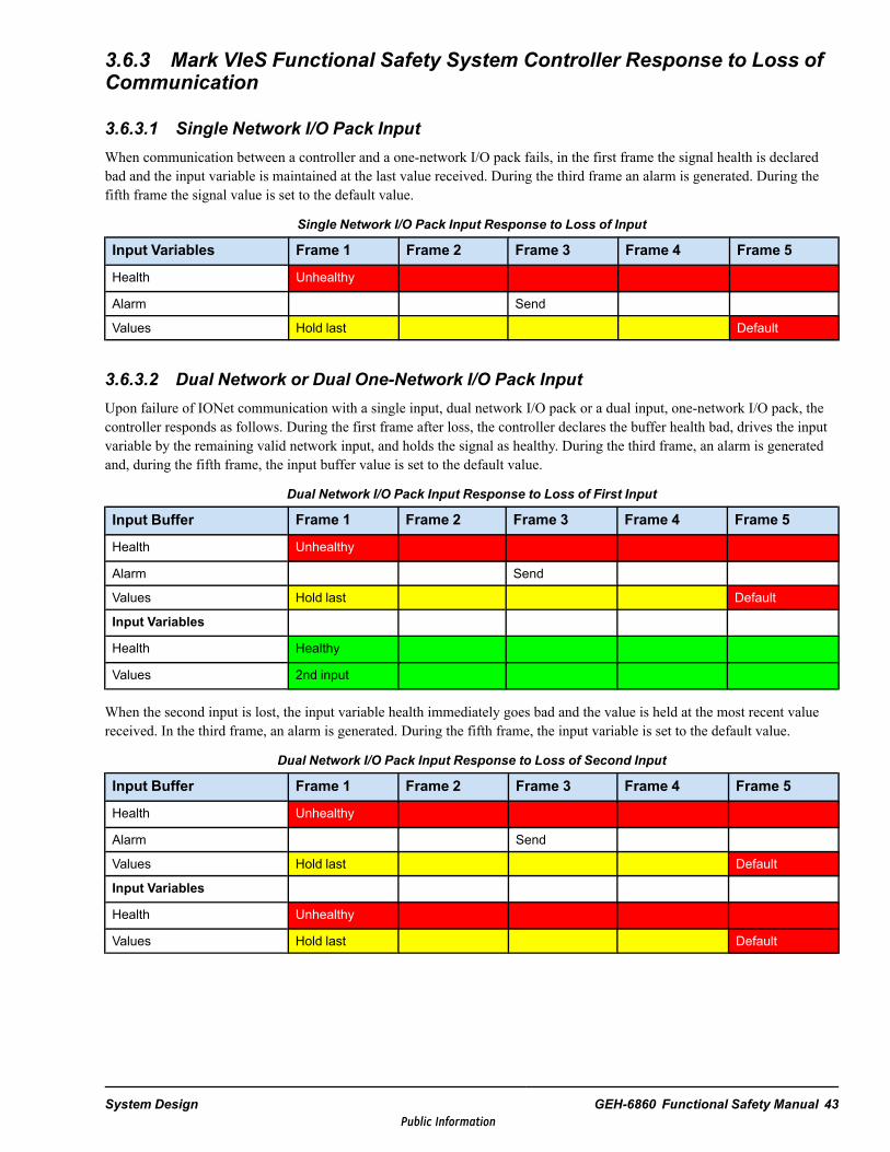
3.6.3.1 Single Network I/O Pack InputWhen communication between a controller and a one-network I/O pack fails, in the first frame the signal health is declaredbad and the input variable is maintained at the last value received. During the third frame an alarm is generated. During thefifth frame the signal value is set to the default value.
Single Network I/O Pack Input Response to Loss of Input
Input Variables Frame 1 Frame 2 Frame 3 Frame 4 Frame 5
Health Unhealthy
Alarm Send
Values Hold last Default
3.6.3.2 Dual Network or Dual One-Network I/O Pack InputUpon failure of IONet communication with a single input, dual network I/O pack or a dual input, one-network I/O pack, thecontroller responds as follows. During the first frame after loss, the controller declares the buffer health bad, drives the inputvariable by the remaining valid network input, and holds the signal as healthy. During the third frame, an alarm is generatedand, during the fifth frame, the input buffer value is set to the default value.
Dual Network I/O Pack Input Response to Loss of First Input
Input Buffer Frame 1 Frame 2 Frame 3 Frame 4 Frame 5
Health Unhealthy
Alarm Send
Values Hold last Default
Input Variables
Health Healthy
Values 2nd input
When the second input is lost, the input variable health immediately goes bad and the value is held at the most recent valuereceived. In the third frame, an alarm is generated. During the fifth frame, the input variable is set to the default value.
Dual Network I/O Pack Input Response to Loss of Second Input
Input Buffer Frame 1 Frame 2 Frame 3 Frame 4 Frame 5
Health Unhealthy
Alarm Send
Values Hold last Default
Input Variables
Health Unhealthy
Values Hold last Default
System Design GEH-6860 Functional Safety Manual 43Public Information

3.6.3.3 Triple Redundant I/O Pack InputThe controller response to the loss of triple redundant input signals depends on the number of lost inputs. Upon loss of thefirst input signal, the prevote buffer for the lost signal is identified as unhealthy, held at the previous value for one frame, andset to the default value during successive frames. During the third frame, an alarm is generated, the input variable healthremains good (HFT of 1), and the voted variable remains valid.
Controller Response to Loss of First Input
Prevote Buffer Frame 1 Frame 2 Frame 3 Frame 4 Frame 5Health Unhealthy
Alarm Send
Values Hold last Default
Input Variables
Health Healthy
Values Voted
Upon loss of the second input, the input variable health is immediately set to Unhealthy and, for one frame, the prevote bufferis held at the most recent value. During the second frame, the input variable value is set to the default value. An alarm isgenerated during the third frame.
Controller Response to Loss of Second Input
Prevote Buffer Frame 1 Frame 2 Frame 3 Frame 4 Frame 5Health Unhealthy
Alarm Send
Values Hold last Default
Input Variables
Health Unhealthy
Values Voted Default (from vote)
Upon loss of the third input, the input variable health is immediately set to Unhealthy and, for one frame, the prevote buffer isheld at the most recent value. During the first frame, the input variable value is set to the default value. An alarm is generatedduring the third frame.
Controller Response to Loss of Third Input
Prevote Buffer Frame 1 Frame 2 Frame 3 Frame 4 Frame 5Health Unhealthy
Alarm Send
Values Hold last Default
Input Variables
Health Unhealthy
Values Default (from vote)
44 GEH-6860 GEH-6860 MMark VIeS Control General Market Functional Safety ManualPublic Information

3.6.4 I/O Pack Response to Loss of Communication
3.6.4.1 Single Network I/O Pack OutputWhen an output pack does not receive communications from the controller, it holds the last value for one frame, goes to thedefined condition in the second frame, and generates an alarm in the third frame. The defined output condition defaults to thepower-down state and should be used in most safety systems. Options are provided so that the I/O pack continues to hold themost recent output or goes to a pre-defined output.
Single Network I/O Pack Output Response to Loss of Input
Outputs Frame 1 Frame 2 Frame 3
Health Healthy Unhealthy
Alarm Send
Values Hold last Standby
3.6.4.2 Dual Network I/O Pack OutputWhen an output pack features two network inputs it responds to the loss of one network by using the output command fromthe other network. This selection takes place within the frame time and generates no observable fall-over time from the I/Opack. The command from the lost network is held for one frame and declared unhealthy in the second frame. An alarm is sentin the third frame.
Loss of First Input, Dual Network I/O Pack Output Response
Input Buffer Frame 1 Frame 2 Frame 3
Health Healthy Unhealthy
Alarm Send
Values Hold last Zero
Outputs
Health Healthy
Values 2nd input
When the second network is lost (both networks lost), the behavior is similar to the single network input pack. The output isheld for the first frame after loss of command. In the second frame, the output moves to the defined condition and the outputhealth is marked as bad. An alarm is generated in the third frame.
Loss of Second Input, Dual Network I/O Pack Output Response
Input Buffer Frame 1 Frame 2 Frame 3
Health Healthy Unhealthy
Alarm Send
Values Hold last Zero
Outputs
Health Healthy Unhealthy
Values Hold last Standby
System Design GEH-6860 Functional Safety Manual 45Public Information

3.7 Failure Analysis ProbabilityReliability parameters for a given SIF are calculated using Markov models and the appropriate failure rates from the MarkVIeS failure modes, effects, and diagnostic analysis (FMEDA). For low-demand mode applications the PFDavg is calculated,while for high demand mode applications the PFH is calculated. In addition, the mean time to fail spurious (MTTFS) iscalculated for both modes.
For the default Markov model calculation, the analysis assumes a SIF with three analog input, two digital input, and twodigital output signals. The following table displays the results of the Markov model calculation for several Mark VIeSFunctional Safety System configurations in low-demand mode applications. A proof test interval (PTI) of one, two, and threeyears is used, assuming a perfect proof test.
Markov Model Calculation for Several Mark VIeS Functional Safety System Configurations
Configuration PFDavg MTTFS [yrs]
PTI 1 yr PTI 2 yr PTI 3 yr PTI 1 yr PTI 2 yr PTI 3yr
Simplex 1 out of 1 0.00412 0.0082 0.0123 20.3 20.39 20.47
Dual 1 out of 2 0.000126 0.000272 0.000438 10.27 10.29 10.31
Dual 2 out of 2 0.00348 0.0069 0.0103 15.79 15.77 15.75
TMR 2 out of 3 0.000147 0.000354 0.000616 300.63 193.09 145.12
The following table displays the results of the Markov model calculation for two Mark VIeS Functional Safety Systemconfigurations in high-demand mode applications.
Markov Model Calculation for Two Mark VIeS Functional Safety System Configurations
Configuration PFH [hr-1] MTTFS [yrs]
Dual 1 out of 2 0.0000000644 4.74
TMR 2 out of 3 0.0000000367 139.02
46 GEH-6860 GEH-6860 MMark VIeS Control General Market Functional Safety ManualPublic Information
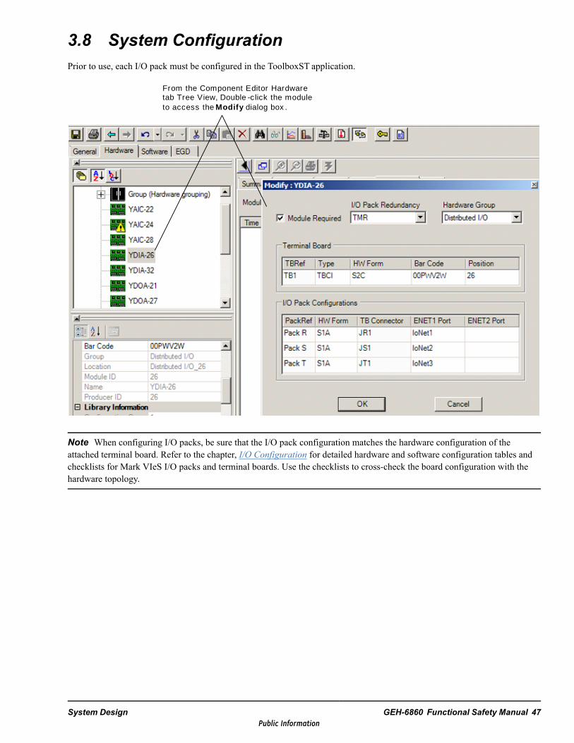
3.8 System ConfigurationPrior to use, each I/O pack must be configured in the ToolboxST application.
From the Component Editor Hardware tab Tree View, Double -click the module to access the Modi f y dialog box .
Note When configuring I/O packs, be sure that the I/O pack configuration matches the hardware configuration of theattached terminal board. Refer to the chapter, I/O Configuration for detailed hardware and software configuration tables andchecklists for Mark VIeS I/O packs and terminal boards. Use the checklists to cross-check the board configuration with thehardware topology.
System Design GEH-6860 Functional Safety Manual 47Public Information

3.8.1 YAIC Analog Input/OutputThe Analog Input/Output (YAICS1B) I/O pack provides the electrical interface between one or two IONets and a terminalboard. The pack handles up to 10 analog inputs, the first 8 of which can be configured as ±5 Vor ±10 V inputs, or 4-20 mAcurrent inputs. The last two inputs can be configured as ±1 mA or 4-20 mA inputs. Using 4-20 mA inputs yields better DCthan voltage inputs.
In the Mark VIeS Functional Safety System, the YAIC is compatible with the TBAIS1C and STAIS2A terminal boards. YAICis only compatible with the S1C version of TBAI and will report a board compatibility problem with any other version.
SIL capability is as follows:
• SIL 2 in HFT = 0 architectures (1 out of 1, 2 out of 2)• SIL 3 in HFT = 1 architectures (1 out of 2, 2 out of 3)
3.8.1.1 TBAI Analog Input/OutputThe Analog Input/Output (TBAIS1C) terminal board holds 10 analog inputs and 2 outputs connected directly to two terminalblocks mounted on the board. Each block has 24 terminals that accept up to #12 AWG wires. A shield terminal attachmentpoint is located adjacent to each terminal block.
The TBAI can hold the following inputs and outputs:
• Analog input -two-wire, three-wire, and four-wire transmitter• Analog input, externally powered transmitter• Analog input, voltage ±5 V, ±10 V dc• Analog output, 0-20 mA
A 24 V dc power supply is available on the terminal board for all transducers. The inputs can be configured as either voltageor current signals. The two analog output circuits are 4-20 mA. TBAI can be used with one or three YAIC I/O packs. DualYAICs on TBAI are not supported.
TBAI I/O Capacity
Quantity Analog Input Types
8 ±10 V dc, or ±5 V dc, or 4-20 mA
2 4-20 mA, or ±1 mA
Quantity Analog Output Types
2 0-20 mA
3.8.1.2 STAI Simplex Analog InputThe Simplex Analog Input (STAI) terminal board holds 10 analog inputs and 2 analog outputs connected to a high-densityEuro-block type terminal block. STAI is designed for DIN-rail or flat mounting. It can hold the same inputs and outputs as theTBAI terminal board.
A 24 V dc power supply is available on the terminal board for all transducers. The inputs can be configured as either voltageor current signals. The two analog output circuits are 0-20 mA.
STAI Input Capacity
Quantity Analog Input Types
8 ±10 V dc, or ±5 V dc, or 4-20 mA
2 4-20 mA, or ±1 mA
Quantity Analog Output Types
2 0-20 mA
48 GEH-6860 GEH-6860 MMark VIeS Control General Market Functional Safety ManualPublic Information
3.8.2 YDIA Discrete InputThe Discrete Input (YDIAS1B) pack provides the electrical interface between one or two IONets and a terminal board. TheI/O pack accepts up to 24 contact inputs and terminal board specific feedback signals, and supports three different voltagelevels. YDIA is compatible with seven terminal boards.
SIL capability is as follows:
• SIL 2 in HFT = 0 architectures (1 out of 1, 2 out of 2)• SIL 3 in HFT = 1 architectures (1 out of 2, 2 out of 3)
3.8.2.1 TBCI Contact Input with Group IsolationThe Contact Input with Group Isolation (TBCI) terminal board accepts 24 dry contact inputs wired to two barrier typeterminal blocks. DC power is provided for contact excitation. TBCI accepts one, two, or three YDIA I/O packs. Two versionsof TBCI are available for use with the Mark VIeS Functional Safety System.
TBCI Input Capacity
Terminal Board Contact Inputs Excitation Voltage
TBCIS2C 24 Nominal 24 V dc, floating, ranging from 16 to 32 V dc
TBCIS3C 24 Nominal 48 V dc, floating, ranging from 32 to 64 V dc
3.8.2.2 STCI Simplex Contact InputThe Simplex Contact Input (STCI) terminal board accepts 24 contact inputs wired to a Euro-block type terminal block. TheSTCI is designed for DIN-rail or flat mounting and accepts a single YDIA. Two versions of STCI are available for use withthe Mark VIeS Functional Safety System.
STCI Input Capacity
Terminal Board Contact Inputs TB Type Excitation Voltage
STCIS2A 24 Pluggable Nominal 24 V dc, floating, ranging from 16 to 32 V dc
STCIS4A 24 Pluggable Nominal 48 V dc, floating, ranging from 32 to 64 V dc
System Design GEH-6860 Functional Safety Manual 49Public Information
3.8.3 YDOA Discrete OutputThe Discrete Output (YDOAS1B) I/O pack provides the electrical interface between one or two IONets and a terminal board.YDOA is capable of controlling up to 12 electromagnetic or solid-state relays and accepts terminal board specific feedback.YDOA is compatible with six terminal boards.
SIL capability is as follows:
• SIL 2 in HFT = 0 architectures (1 out of 1, 2 out of 2)• SIL 3 in HFT = 1 architectures (1 out of 2, 2 out of 3)
3.8.3.1 TRLYS1B Relay Output with Coil SensingThe Relay Output with coil sensing (TRLYS1B) terminal board accepts 12 relay outputs wired directly to two barrier typeterminal blocks. Each block has 24 terminals that accept up to #12 AWG wires.
The first six relay circuits are jumper configurable either for dry, Form-C contact outputs, or to drive external solenoids. Astandard 125 V dc or 115/230 Vac source, or an optional 24 V dc source, can be provided for field solenoid power. The nextfive relays are unpowered isolated Form-C contacts. Output 12 is an isolated Form-C contact, used for special applicationsrequiring dedicated power from connector JG1. TRLYS1B supports a single YDOA on connector JA1, or three YDOAs onconnectors JR1, JS1, and JT1. The fuses should be removed for isolated contact applications to ensure that suppressionleakage is removed from the power bus.
Note Jumpers JP1-JP6 are removed in the factory and shipped in a plastic bag. Re-install the appropriate jumper if power toa field solenoid is required. Conduct individual loop energized checks as per standard practices, and install the jumpers asrequired.
3.8.3.2 TRLYS1D Relay Output with Servo SensingThe Relay Output with servo sensing (TRLYS1D) terminal board holds six plug-in magnetic relays wired to a barrier typeterminal block. The six relay circuits are Form-C contact outputs, powered and fused to drive external solenoids. A standard24 V dc or 125 V dc source can be used. TRLYS1D supports a single YDOA on connector JA1, or three YDOAs onconnectors JR1, JS1, and JT1.
3.8.3.3 TRLYS#F Relay Output with TMR Contact VotingThe Relay Output with TMR contact voting (TRLYS1F or S2F) terminal board provides 12 contact-voted relay outputs.TRLYS1F holds 12 sealed relays in each TMR section, for a total of 36 relays among three boards. The relay contacts from R,S, and T are combined to form a voted Form A normally open (NO) contact. 24/125 V dc or 115 Vac power can be applied.Three YDOA packs plug into the JR1, JS1, and JT1 37-pin D-type connectors on the terminal board. TRLYS#F does not havepower distribution or support simplex systems.
Note TRLYS2F is the same as TRLYS1F except that voted contacts form a Form B normally closed (NC) output.
3.8.3.4 SRLY Simplex Relay OutputThe Simplex Relay Output (SRLY) terminal board provides 12 form C relay contact outputs wired to a Euro-style boxterminal block. Each of 12 sealed relays uses an isolated contact set for relay position feedback. The SRLYaccepts a singleYDOA, which can have one or two network connections.
50 GEH-6860 GEH-6860 MMark VIeS Control General Market Functional Safety ManualPublic Information

3.8.4 YVIB Vibration InputThe Vibration Input (YVIBS1B) pack provides the electrical interface between one or two IONets and a terminal board. thepack handles up to 13 inputs. The first 8 can be configured to read vibration or proximity sensors, channels 9-11 supportposition sensors only, and channels 12 and 13 can be configured to support either position sensors or KeyPhasor transducers.The terminal board also supports non-safety buffered outputs of the input signals. The YVIBS1B I/O pack is rated SIL 2 withHFT of zero. In the Mark VIeS Functional Safety System, the TVBAS2B terminal board is used with the YVIBS1B.
SIL capability is as follows:
• SIL 2 in HFT = 0 architectures (1 our of 1, 2 out of 2)• SIL 3 in HFT = 1 architectures (1 our of 2, 2 out of 3)
3.8.5 TVBAVibration InputThe Vibration Input (TVBAS2B) terminal board provides 8 vibration inputs, 3 position inputs, an additional 2 position orKeyphasor inputs, and non-safety rated buffered outputs connected directly to two terminal blocks mounted on the board.Each block has 24 terminals that accept up to #12 AWG wires. A shield terminal attachment point is located adjacent to eachterminal block. The TVBA can hold the following inputs and outputs:
• Vibration input Proximeters, Seismics, and Velomitor* sensor channels 1-8; Accelerometers (channels 1, 2, and 3 only)• Position inputs Proximeters channels 9-11• Keyphasor transducer input Proximiter sensor channels 12 and 13• Non-safety rated, buffered outputs of the inputs
The first eight inputs are jumper configured:
• Jumpers J1A through J8A− Seismic (S)− Prox or Accel (P, A)− Velomitor sensor (V)
• Jumpers J1B through J8B− Prox, Velomitor sensor or Accel (P, V, A)− Seismic (S)
• Jumpers J1C through J8C− PCOM provides N28 return path for power− OPEN no N28 return path through terminal board
System Design GEH-6860 Functional Safety Manual 51Public Information

3.8.6 YUAA Universal AnalogThe Universal Analog (YUAAS1A) I/O pack provides the electrical interface between one or two IONets and the SUAAS1Aterminal board. Using the ToolboxST application, 16 Simplex Analog channels can be individually configured as any of thefollowing types: Thermocouple, RTD, Voltage Input (± 5 Vor ± 10 V), 4–20 mA Current Input, 0–20 mA Current Output,Pulse Accumulator, or Digital Input. The YUAA I/O pack is rated SIL 2 with HFT of zero. YUAAS1A is compatible with theSUAAS1A terminal board. The orderable part number is IS430SSUAH1A.
SIL capability is as follows:
• SIL 2 in HFT = 0 architectures (1 out of 1, 2 out of 2)• SIL 3 in HFT = 1 architectures (1 out of 2, 2 out of 3)
Note For further details on the YUAA I/O pack, refer to the Mark VIeS Functional Safety Systems for General MarketVolume II: System Guide for General-purpose Applications (GEH-6855_Vol_II), the chapter YUAA Universal I/O Modules.
3.8.6.1 SUAA Universal Analog Terminal BoardThe Universal Analog (SUAA) terminal board provides 16 Analog inputs that route directly to the YUAA electrical interface.The terminal blocks are removable on a per-channel basis due to how the points are grouped together as PWR_RTN, IO+, andIO-, respectively. Each terminal screw can accept a 24 - 12 AWG wire size. A shield terminal attachment point is locatedadjacent to each terminal block.
There are no jumpers on the SUAA terminal board to configure.
52 GEH-6860 GEH-6860 MMark VIeS Control General Market Functional Safety ManualPublic Information

3.9 Power SourcesThe Mark VIeS Functional Safety System is designed to operate on a flexible selection of power sources. Power distributionmodules (PDM) support the use of 115/230 Vac, 24 V dc, and 125 V dc power sources in many redundant combinations. Theapplied power is converted to 28 V dc for I/O pack operation. The controllers may operate from the 28 V dc I/O pack poweror from direct 24 V dc battery power. Alternate power sources are acceptable if I/O pack power is regulated to be within ±5%of 28 V dc and over-voltage protection is provided by the power source. The extensive power feedback signals designed intothe power distribution system are not critical to system safety but do provide useful information to assist in systemmaintenance.
Note For further details on the PDM, refer to theMark VIeS Functional Safety Control Systems PDM Application Guide forGeneral Market (GEI-100861).
All Mark VIeS Functional Safety System I/O packs include a circuit breaker at the 28 V dc power input that limits theavailable fault current. The breaker also provides soft-start, permitting the application of power to an I/O pack withoutconcern for other connected loads. All I/O packs monitor input voltage for undervoltage conditions. The voltage monitoringfunction provides alarms at 25.1 V dc (28 V -5%) and 16 V dc.
When the input voltage drops below 25.1 V dc, an alarm is generated. The I/O pack continues to operate, but performance isdegraded. For example, on terminal boards with 24 V dc power sources for powered field devices, the voltage begins to dropbelow 24 V dc and the available drive voltage for analog output is diminished. Action should be taken to begin an orderlyshut-down of equipment protected by the affected SIFs. I/O pack operation will continue to permit a controlled shutdown.
When the input voltage drops below 16 V dc, another alarm is generated. An output I/O pack enters its power-down state, thesafe state for all but energize-to-trip SIFs. The following figures display an example of the power loss application in theToolboxST application:
Input Variables
System Design GEH-6860 Functional Safety Manual 53Public Information
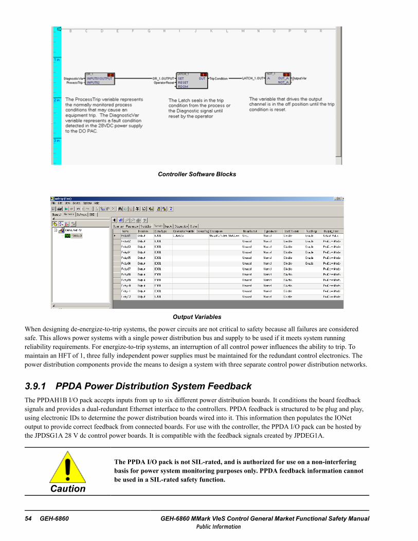
Controller Software Blocks
Output Variables
When designing de-energize-to-trip systems, the power circuits are not critical to safety because all failures are consideredsafe. This allows power systems with a single power distribution bus and supply to be used if it meets system runningreliability requirements. For energize-to-trip systems, an interruption of all control power influences the ability to trip. Tomaintain an HFT of 1, three fully independent power supplies must be maintained for the redundant control electronics. Thepower distribution components provide the means to design a system with three separate control power distribution networks.
3.9.1 PPDA Power Distribution System FeedbackThe PPDAH1B I/O pack accepts inputs from up to six different power distribution boards. It conditions the board feedbacksignals and provides a dual-redundant Ethernet interface to the controllers. PPDA feedback is structured to be plug and play,using electronic IDs to determine the power distribution boards wired into it. This information then populates the IONetoutput to provide correct feedback from connected boards. For use with the controller, the PPDA I/O pack can be hosted bythe JPDSG1A 28 V dc control power boards. It is compatible with the feedback signals created by JPDEG1A.
Caution
The PPDA I/O pack is not SIL-rated, and is authorized for use on a non-interferingbasis for power system monitoring purposes only. PPDA feedback information cannotbe used in a SIL-rated safety function.
54 GEH-6860 GEH-6860 MMark VIeS Control General Market Functional Safety ManualPublic Information

4 Installation, Commissioning, andOperation4.1 InstallationDuring installation, complete the following items:
• Documentation of a functional safety management plan, including:− Organization and resources− Risk evaluation and management to identify safety hazards− Safety planning, implementing, and monitoring− Functional safety assessment, auditing, and revisions− System configuration management
• Clear documentation of the required hardware and programmable logic for each safety loop• Safety function validation tests plans• Functional testing of each safety loop conducted under site environmental conditions• Records of functional tests
4.2 CommissioningDuring commissioning, the following items should be checked:
• All wiring is in accordance with design• All software and firmware is up-to-date• Test instrumentation is calibrated• No diagnostics are present in hardware or software• System is properly configured (configuration checklist verified)• Power supplies are of proper type and in good working order• All forcing points are removed prior to engaging Locked mode
Installation, Commissioning, and Operation GEH-6860 Functional Safety Manual 55Public Information

4.3 OperationTo maintain safety integrity during normal operations, the following checks and periodic proof tests must be conducted toexpose any DU hazards.
• Proof test intervals must be calculated for each SIF• Proof tests must be conducted to ensure that the functional safety as designed is maintained and test results recorded• All diagnostic alarms must be identified and corrected. Check the front lights on the I/O pack when performing this task.• Contact GE if a fault is encountered.
4.3.1 Variable HealthThe Mark VIeS Functional Safety System detects I/O pack failures, defaults input data, and generates alarms as appropriate.The application code can be alerted to this type of failure by monitoring the health of critical input variables using the VAR_HEALTH block.
4.3.2 Alarming on DiagnosticsAlert an operator when a diagnostic alarm is active in the control system. Every pack and controller has a configurationvariable L3Diag that is driven to the active state when there is an active diagnostic alarm in the device. Configure thesevariables as alarms in the application code so that they are available through the Alarm Viewer.
4.3.3 I/O Pack Status LEDsDuring system operation, alarms or diagnostics must be promptly addressed. The following is a partial listing of I/O packstatus LEDs.
A green LED labeled PWR indicates the presence of control power.A red LED labeled ATTN indicates five different pack conditions as follows:
• LED out -no detectable problems with the pack• LED solid on – a critical fault is present that prevents the pack from operating.
Critical faults include detected hardware failures on the processor or acquisitionboards, or no application code loaded.
• LED flashing quickly (¼ second cycle) – an alarm condition is present in the packsuch as putting the wrong pack on the terminal board, or there is no terminal board,or there were errors loading the application code.
• LED flashing at medium speed (¾ second cycle) – the pack is not online• LED flashing slowly (two second cycle) – the pack has received a request to flash
the LED to draw attention to the pack. This is used during factory test or as an aidto confirm physical location against ToolboxST settings.
A green LED labeled LINK is provided for each Ethernet port to indicate that a validEthernet connection is present.
56 GEH-6860 GEH-6860 MMark VIeS Control General Market Functional Safety ManualPublic Information
4.3.4 RestrictionsRestrictions in the Mark VIeS Functional Safety System are as follows:
• The IS420UCSCS2A and IS420UCSCH1B are the only controller types certified for use with the Mark VIeS FunctionalSafety System system.− IS420UCSCS2A:
Does not support Modbus, and only supports 40, 80 and 160 ms frame periods Compatible with all YxxxS1B I/O modules
− IS420UCSCS2A and IS420UCSCH1B: Supports both Modbus and the 10, 40, 80 and 160 ms frame periods Compatible with all YxxxS1B I/O modules running at 10, 40, 80 and 160 ms frame periods
− Frame idle time must be above 30%. Frame idle time should be periodic as the set of operations implemented in aframe is fixed for a given configuration. It can be monitored for a controller using the FrameIdleTime_x intrinsicvariables on Trender or calculating a minimum using blockware. Frame idle time is calculated in the controller everyframe.
Note To measure minimum frame idle time, measurements must be taken with all inputs healthy and separatelywith at least one input module unhealthy (for example, with the Ethernet cable removed from the I/O module). Inmost cases, the scenario with at least one input module unhealthy will have a lower frame idle time.
− Average system idle time must be above 30%. System idle time is not periodic because of many features that areinterrupt-based rather than frame based, such as UDH EGD consumption, communications with ToolboxST/HMI,and so forth. System idle time can be monitored for a controller using the IdleTime_x intrinsic variables on Trenderand is calculated as a 1 second average. It is acceptable for measured system idle time to dip below 30%, but thismust only occur less than 10% of the time.
− At frame periods of 40, 80 and 160 ms, any combination of the Safety I/O modules is allowed, up to a maximum of50 modules per IONet
− At a frame period of 10 ms, any combination of Safety I/O modules is allowed such that all frame input clientscomplete within 1.6 ms after the start of the frame
Note 1.6 ms allows for a required 20% safety margin.
Execution time of the frame input clients varies based on the following user configurable items:
• Controller type
• Number of I/O modules
• Types of I/O modules
• Number of voted Boolean variables
• Number of voted Analog variables
For additional information, refer to the Appendix Determine Frame Input Client Completion Time.
• Use only GE approved Ethernet switches in the Mark VIeS Functional Safety System I/O network.• YVIBS1B buffered outputs are not safety-certified.• SRLYS2A optional fused power distribution daughterboard WROx may only be used for power distribution, fuse
diagnostic feedback signals are not safety certified.• IR interface to the I/O packs is prohibited while functioning as a safety control.• The Mark VIeS Functional Safety System allows communication with other controllers and Human-machine Interface
(HMI) devices through the UDH protocol. The UDH communication channel is not safety-certified so any data accessed
Installation, Commissioning, and Operation GEH-6860 Functional Safety Manual 57Public Information

from UDH and used within a safety loop should be verified by the application code using appropriate measures.Commands from the HMI devices (for example setpoint changes) are not accepted by the Mark VIeS Functional SafetySystem.
• The presence of active diagnostic alarms in the control system indicates that safety functions may be compromised. Alldiagnostics should be cleared prior to startup and any diagnostic that occurs should be attended to in a timely fashion.
• Feedback values from the PPDA cannot be used for SIL-rated safety functionality. The PPDA is approved fornon-interfering, power distribution system monitoring purposes only.
• The master reset should be cleared before engaging safety control. The Master Reset command is issued by the controllerto the I/O packs to reset any existing trips or suicide latches. If the fault condition remains after the reset has been issued,the trip or suicide is issued again. Because the I/O packs evaluate the Master Reset command at each run cycle, the I/Opacks toggle between the cleared and faulted condition if the command remains active for an extended time and apersistent fault condition is present. To prevent this, the Master Reset command must be pulsed to the I/O packs andremain active for at least two frames before returning to the inactive state. The following figure displays the applicationcode that implements this function.
Pulsed Master Reset
4.4 Product LifeDuring operation and maintenance, the following product life guidelines should be followed:
• The I/O packs have no known wear-out mechanism and do not require periodic maintenance.• There are no wear items on the UCSCS2A or the UCSCH1B controllers such as exist with I/O packs.• The terminal boards have no known wear-out mechanism and do not require periodic maintenance.• The bulk 28 V dc power supplies have internal capacitors with finite life. Replacement of the power supplies should be
scheduled every 15 years.• The recommended Ethernet switches have internal power supply capacitors with finite life. Replacement of the switches
should be scheduled every 15 years.• Capacitor life predictions are based on an average ambient temperature of 35ºC (95 ºF). Capacitor life is reduced by ½ for
every 10ºC (18 ºF) of average temperature above 35ºC (95 ºF).
58 GEH-6860 GEH-6860 MMark VIeS Control General Market Functional Safety ManualPublic Information

5 I/O ConfigurationThis chapter contains tables that should be used as checklists for I/O point configuration. Copies of each table should be madeand the appropriate values either checked or written in the final column. The ToolboxST module configuration should beverified against the installed I/O module hardware.
To verify terminal board configuration
1. Upon initial installation, prior to securing the module cover, locate and record the terminal board information.
a. The terminal board part number contains the Type and Form information.
IS410 TBAI S1C[Type] [Form]
b. Record the terminal board barcode. This must be entered into the ToolboxST module configuration if offline or thereis an ellipse that can automatically detect this ID if online.
I/O Configuration GEH-6860 Functional Safety Manual 59Public Information
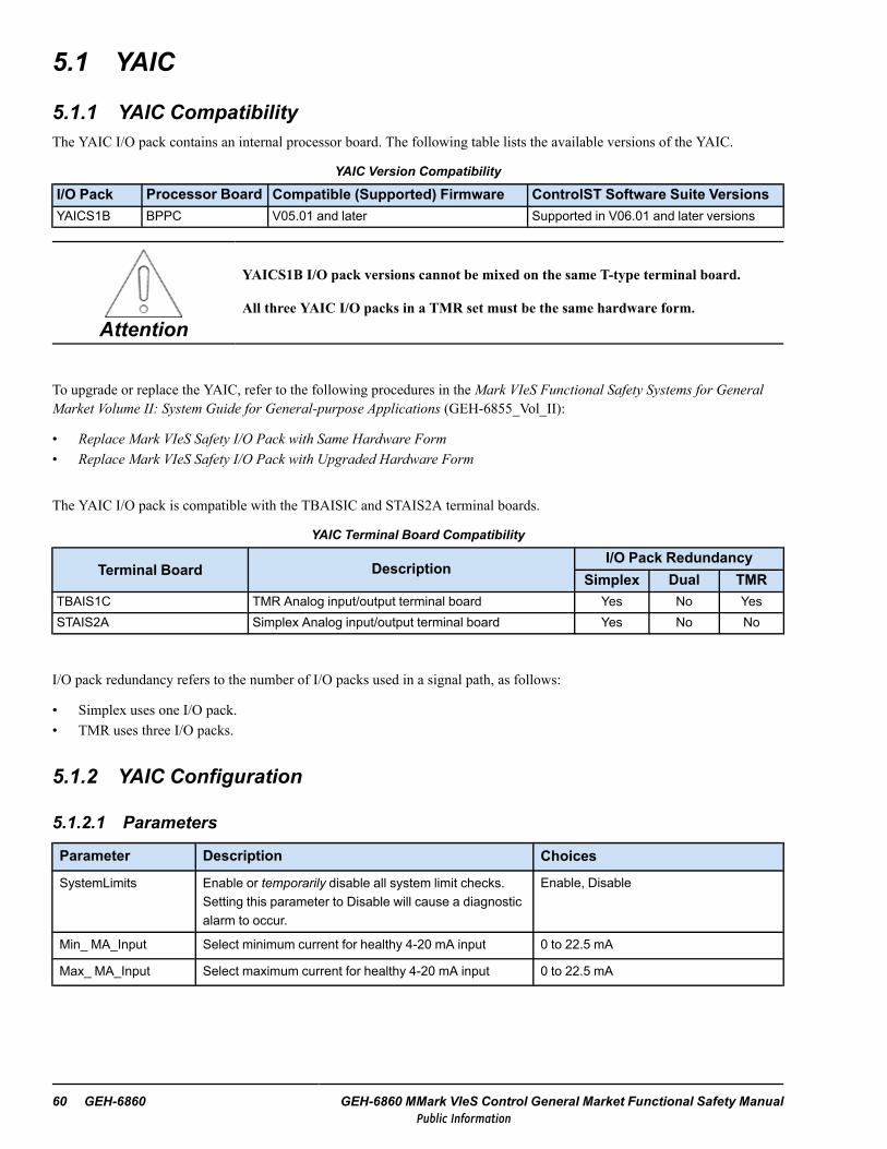
5.1 YAIC
5.1.1 YAIC CompatibilityThe YAIC I/O pack contains an internal processor board. The following table lists the available versions of the YAIC.
YAIC Version Compatibility
I/O Pack Processor Board Compatible (Supported) Firmware ControlST Software Suite VersionsYAICS1B BPPC V05.01 and later Supported in V06.01 and later versions
Attention
YAICS1B I/O pack versions cannot be mixed on the same T-type terminal board.
All three YAIC I/O packs in a TMR set must be the same hardware form.
To upgrade or replace the YAIC, refer to the following procedures in theMark VIeS Functional Safety Systems for GeneralMarket Volume II: System Guide for General-purpose Applications (GEH-6855_Vol_II):
• Replace Mark VIeS Safety I/O Pack with Same Hardware Form• Replace Mark VIeS Safety I/O Pack with Upgraded Hardware Form
The YAIC I/O pack is compatible with the TBAISIC and STAIS2A terminal boards.
YAIC Terminal Board Compatibility
Terminal Board DescriptionI/O Pack Redundancy
Simplex Dual TMRTBAIS1C TMR Analog input/output terminal board Yes No YesSTAIS2A Simplex Analog input/output terminal board Yes No No
I/O pack redundancy refers to the number of I/O packs used in a signal path, as follows:
• Simplex uses one I/O pack.• TMR uses three I/O packs.
5.1.2 YAIC Configuration
5.1.2.1 Parameters
Parameter Description Choices
SystemLimits Enable or temporarily disable all system limit checks.Setting this parameter to Disable will cause a diagnosticalarm to occur.
Enable, Disable
Min_ MA_Input Select minimum current for healthy 4-20 mA input 0 to 22.5 mA
Max_ MA_Input Select maximum current for healthy 4-20 mA input 0 to 22.5 mA
60 GEH-6860 GEH-6860 MMark VIeS Control General Market Functional Safety ManualPublic Information

5.1.2.2 Inputs
Input Description ChoicesAnalogInput01throughAnalogInput10
First of 10 Analog Inputs – board point. Point edit (Input REAL)
InputType Current or voltage input type Unused or 4-20 mA (for all Analog Inputs)±5 V or ±10 V (for AnalogInput01 to 08 only)±1 mA (for AnalogInput09 and 10 only)
Low_Input Value of input current (mA) or voltage (V) at low end of input scale -10 to 20
Low_Value Value of input in engineering units at Low_Input -3.4082 e + 038 to 3.4028 e + 038
High_Input Value of input current (mA) or voltage (V) at high end of input scale -10 to 20
High_Value Value of input in engineering units at High_Input -3.4082 e + 038 to 3.4028 e + 038
InputFilter Bandwidth of input signal filter Unused, 0.75hz, 1.5hz, 3hz, 6hz, 12hz
TMR_DiffLimit Difference limit for voted inputs in % of High_Value - Low_Value 0 to 200
SysLim1Enabl Enable System Limit 1 fault check Enable, Disable
SysLim1Latch System Limit 1 fault latch - if set, requires a Reset System Limits(RSTSYS) on SYS_OUTPUTS block to clear
Latch, NotLatch
SysLim1Type System Limit 1 Check Type >= or <=
SysLim1 System Limit 1 in engineering units -3.4082 e + 038 to 3.4028 e + 038
SysLim2Enabl Enable System Limit 1 fault check Enable, Disable
SysLim2Latch System Limit 2 fault latch - if set, requires a Reset System Limits(RSTSYS) on SYS_OUTPUTS block to clear
Latch, NotLatch
SysLim2Type System Limit 2 Check Type >= or <=
SysLimit2 System Limit 2 in Engineering Units -3.4082 e + 038 to 3.4028 e + 038
DiagHighEnab Enables the generation of a high limit diagnostic alarm when thevalue of the 4-20 mA input is greater than the value of parameterMax_MA_Input
Enable, Disable
DiagLowEnab Enables the generation of a low limit diagnostic alarm when thevalue of the 4-20 mA input is less than the value of parameter Min_MA_Input
Enable, Disable
TMR_DiffLimt Diag limit, TMR input vote difference, in percent of (High_Value -Low_Value)
0 to 200 %
I/O Configuration GEH-6860 Functional Safety Manual 61Public Information

5.1.2.3 Outputs
Output Name Output Description ChoicesAnalogOutput01 -AnalogOutput02
First of two analog outputs - board point, Point edit Output REAL
Output_MA Output current, mA selection. Unused, 0-20 mA
OutputState State of the outputs when offline. When the PAIC losescommunication with the controller, this parameter determineshow it drives the outputs:
PwrDownMode - Open the output relay and drive outputs tozero currentHoldLastVal - Hold the last value received from the controllerOutput_Value - Go to the configured output value set by theparameter Output_Value
PwrDownModeHoldLastValOutput_Value
Output_Value Pre-determined value for the outputs -3.4082 e + 038 to 3.4028 e + 038
Low_MA Output mA at low value 0 to 200 mA
Low_Value Output in Engineering Units at Low_MA -3.4082 e + 038 to 3.4028 e + 038
High_MA Output mA at high value 0 to 200 mA
High_Value Output value in Engineering Units at High_MA -3.4082 e + 038 to 3.4028 e + 038
TMR_Suicide Enables suicide for faulty output current, TMR only Enable, Disable
TMR_SuicLimit Suicide threshold (Load sharing margin) for TMR operation, inmA
0 to 200 mA
D/A_ErrLimit Difference between D/A reference and feedback, in % forsuicide, TMR only
0 to 200 %
Dither_Ampl Dither % current of Scaled Output mA 0 to 10
Dither_Freq Dither rate in Hertz Unused, 12.5hz, 25hz, 33.33hz, 50hz, 100hz
62 GEH-6860 GEH-6860 MMark VIeS Control General Market Functional Safety ManualPublic Information
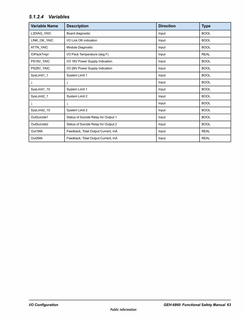
5.1.2.4 Variables
Variable Name Description Direction Type
L3DIAG_YAIC Board diagnostic Input BOOL
LINK_OK_YAIC I/O Link OK indication Input BOOL
ATTN_YAIC Module Diagnostic Input BOOL
IOPackTmpr I/O Pack Temperature (deg F) Input REAL
PS18V_YAIC I/O 18V Power Supply Indication Input BOOL
PS28V_YAIC I/O 28V Power Supply Indication Input BOOL
SysLimit1_1 System Limit 1 Input BOOL
↓ ↓ Input BOOL
SysLimit1_10 System Limit 1 Input BOOL
SysLimit2_1 System Limit 2 Input BOOL
↓ ↓ Input BOOL
SysLimit2_10 System Limit 2 Input BOOL
OutSuicide1 Status of Suicide Relay for Output 1 Input BOOL
OutSuicide2 Status of Suicide Relay for Output 2 Input BOOL
Out1MA Feedback, Total Output Current, mA Input REAL
Out2MA Feedback, Total Output Current, mA Input REAL
I/O Configuration GEH-6860 Functional Safety Manual 63Public Information
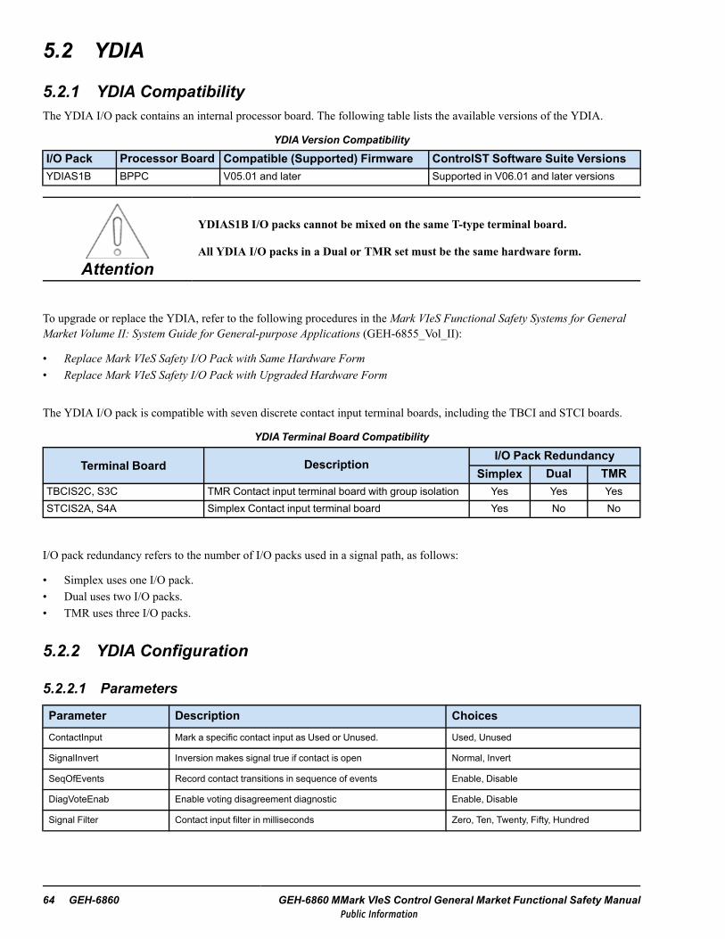
5.2 YDIA
5.2.1 YDIA CompatibilityThe YDIA I/O pack contains an internal processor board. The following table lists the available versions of the YDIA.
YDIAVersion Compatibility
I/O Pack Processor Board Compatible (Supported) Firmware ControlST Software Suite VersionsYDIAS1B BPPC V05.01 and later Supported in V06.01 and later versions
Attention
YDIAS1B I/O packs cannot be mixed on the same T-type terminal board.
All YDIA I/O packs in a Dual or TMR set must be the same hardware form.
To upgrade or replace the YDIA, refer to the following procedures in theMark VIeS Functional Safety Systems for GeneralMarket Volume II: System Guide for General-purpose Applications (GEH-6855_Vol_II):
• Replace Mark VIeS Safety I/O Pack with Same Hardware Form• Replace Mark VIeS Safety I/O Pack with Upgraded Hardware Form
The YDIA I/O pack is compatible with seven discrete contact input terminal boards, including the TBCI and STCI boards.
YDIATerminal Board Compatibility
Terminal Board DescriptionI/O Pack Redundancy
Simplex Dual TMRTBCIS2C, S3C TMR Contact input terminal board with group isolation Yes Yes YesSTCIS2A, S4A Simplex Contact input terminal board Yes No No
I/O pack redundancy refers to the number of I/O packs used in a signal path, as follows:
• Simplex uses one I/O pack.• Dual uses two I/O packs.• TMR uses three I/O packs.
5.2.2 YDIA Configuration
5.2.2.1 Parameters
Parameter Description ChoicesContactInput Mark a specific contact input as Used or Unused. Used, Unused
SignalInvert Inversion makes signal true if contact is open Normal, Invert
SeqOfEvents Record contact transitions in sequence of events Enable, Disable
DiagVoteEnab Enable voting disagreement diagnostic Enable, Disable
Signal Filter Contact input filter in milliseconds Zero, Ten, Twenty, Fifty, Hundred
64 GEH-6860 GEH-6860 MMark VIeS Control General Market Functional Safety ManualPublic Information

5.2.2.2 Inputs
Input Direction Type
Contact01 Input BOOL
↓ ↓ ↓
Contact24 Input BOOL
5.2.2.3 Variables
Note The following variable names are displayed differently depending on redundancy of I/O pack (R, S, or T) and if this isa YDIA I/O pack.
Variable Description Direction Type
LL3DIAG_YDIA_x I/O diagnostic indication, where x is R, S, or T
Input
BOOL
LINK_OK_YDIA_x I/O link okay indication, where x is R, S, or T BOOL
ATTN_YDIA_x I/O attention indication, where x is R, S, or T BOOL
IOPackTmpr_x I/O pack temperature, where x is R, S, or T REAL
PS18V_YDIA_x I/O 18 V power supply indication, where x is R, S, orT
BOOL
PS28V_YDIA_x I/O 28 V power supply indication, where x is R, S, orT
BOOL
I/O Configuration GEH-6860 Functional Safety Manual 65Public Information

5.3 YDOA
5.3.1 YDOA CompatibilityThe YDOA I/O pack contains an internal processor board. One version of the YDOA is available for use with the Mark VIeSFunctional Safety System.
YDOAVersion Compatibility
I/O Pack Processor Board Compatible (Supported) Firmware ControlST Software Suite VersionsYDOAS1B BPPC V05.00 and later Supported in V06.01 and later versions
Attention
YDOAS1B I/O packs cannot be mixed on the same T-type terminal board.
All three YDOA I/O packs in a TMR set must be the same hardware form.
To upgrade or replace the YDOA, refer to the following procedures in the Mark VIeS Functional Safety Systems for GeneralMarket Volume II: System Guide for General-purpose Applications (GEH-6855_Vol_II):
• Replace Mark VIeS Safety I/O Pack with Same Hardware Form• Replace Mark VIeS Safety I/O Pack with Upgraded Hardware Form
YDOA is compatible with several types of discrete (relay) output terminal boards.
YDOATerminal Board Compatibility
Terminal Board DescriptionI/O Pack Redundancy
Simplex Dual TMRTRLYS1B Relay output with coil sensing Yes No YesTRLYS1D Relay output with solenoid integrity sensing Yes No YesTRLYS1F, S2F Relay output with TMR contact voting No No YesSRLYS2A Form C contact relays Yes No No
I/O pack redundancy refers to the number of I/O packs used in a signal path, as follows:
• Simplex uses one I/O pack.• TMR uses three I/O packs.
5.3.2 YDOA ConfigurationYDOA Module
Configuration Description Select Option or Enter Value
I/O pack redundancy I/O pack redundancy SimplexTMR
Hardware group Hardware group Distributed I/O Group
Terminal board Terminal board type/form/barcode
I/O pack configurations Pack form/TB Connector/IONet
66 GEH-6860 GEH-6860 MMark VIeS Control General Market Functional Safety ManualPublic Information

TRLYS1B
Jumper Select
JP1 ExcitedDRY
JP2 ExcitedDRY
JP3 ExcitedDRY
JP4 ExcitedDRY
JP5 ExcitedDRY
JP6 ExcitedDRY
5.3.2.1 Inputs
Parameter Description Select Option or EnterValue
ContactInput Enables Relay#Fdbk Unused, Used
SignalInvert
Inverts Relay#Fdbk signal and Relay#ContactFdbk signal (if available)
Do not rely on the SignalInvert property of digital inputs to invert the value.Implement this operation in the application code with the input connected to aNOT block.
Normal, Invert
SeqOfEventsRecord RelayFdbk transitions in sequence of eventsNot available with TRLY#D.
Disable, Enable
DiagVoteEnab Enable voting disagreement diagnostic Disable, Enable
SignalFilterRelay feedback digital filter in milliseconds, is only available with TRLYH#C (notavailable for safety use)
Zero, Ten, Twenty, Fifty,Hundred
5.3.2.2 Outputs
Parameter Description Select Option or EnterValue
RelayOutput Enable relay output Used, Unused
SignalInvert
Inversion makes relay closed if signal is false
Do not rely on the SignalInvert property of digital inputs to invert the value.Implement this operation in the application code with the input connected to aNOT block.
Normal, Invert
SeqOfEvents Record relay command transitions in sequence of events Disable, EnableFuseDiag Enable fuse diagnostic (if available) Enable, Disable
Output_State Select the state of the relay condition based on I/O pack going offline with controllerPwrDownMode,HoldLastValue, Output_Value
Output_ValuePre-determined value for the outputs (only displayed if Output_State is set toOutput_Value)
Off, On
I/O Configuration GEH-6860 Functional Safety Manual 67Public Information

5.3.2.3 Variables
Name Description Direction TypeL3DIAG_YDOA_x I/O diagnostic indication, where x = R, S, or T Input BOOLLINK_OK_YDOA_x I/O link okay indication, where x = R, S, or T Input BITATTN_YDOA_x I/O Attention Indication, where x = R, S, or T Input BITIOPackTmpr_x I/O pack temperature, where x = R, S, or T Input REAL
†Cap1_Ready_xI/O pack capture buffer 1 ready for upload (currently not used), where x = R, S, orT
Input BIT
†Cap2_Ready_xI/O pack capture buffer 2 ready for upload (currently not used), where x = R, S, orT
Input BIT
†CV_Permissive CV (control valve) permissive for PGEN PLU function Input BIT†IV_Permissive IV (intercept valve) permissive for PGEN PLU function Input BIT† Not applicable to YDOA
Name Description Direction TypeRelay# Relay# output command Output BITRelay#Fdbk Relay# Driver Status (set of 12 relays) Input BITFuse#Fdbk Fuse voltage (if available) Input BIT
Solenoid#StatusSolenoid# Resistance Sense (set of 6 relays), True means resistance within therange, False means resistance out of the range, available for TRLYS1D only
Input BIT
TRLYS1B
Jumper Select
JP1 ExcitedDRY
JP2 ExcitedDRY
JP3 ExcitedDRY
JP4 ExcitedDRY
JP5 ExcitedDRY
JP6 ExcitedDRY
68 GEH-6860 GEH-6860 MMark VIeS Control General Market Functional Safety ManualPublic Information

5.4 YVIB
5.4.1 YVIB CompatibilityThe YVIB I/O pack contains an internal processor board. One version of the YVIB is available for use with the Mark VIeSFunctional Safety System.
YVIB Version Compatibility
I/O Pack Processor Board Compatible (Supported) Firmware ControlST Software Suite VersionsYVIBS1B BPPC V05.01 and later Supported in V06.02 and later versions
Attention
YVIBS1B cannot be mixed on a TMR module.
Attention
If upgrading to YVIBS1B with an existing YVIBS1A configuration, use the ToolboxSTapplication to correct the GAP12 configuration.
After upgrading existing YVIBS1A applications to YVIBS1B, the user may need touse the configurable low-pass filter to roll-off responses to match existingpeak-to-peak calculations. This is because the YVIBS1B has an increased input signalbandwidth of 4500 Hz.
The YVIB I/O pack is compatible with the Vibration (TVBA) terminal board.
YVIB Terminal Board Compatibility
Terminal Board DescriptionI/O Pack Redundancy
Simplex Dual TMR
TVBAS2BSafety vibration terminal board with buffered outputs;N28 function integrated into terminal board and YVIBS-position is lined up vertically with R and T positions.
Yes No Yes
I/O pack redundancy refers to the number of I/O packs used in a signal path, as follows:
• Simplex uses one I/O pack.• TMR uses three I/O packs.
The following table displays the available sensor types per channel for YVIBS1B.
YVIB Supported Sensor Inputs
Sensor Type Typical Application YVIBChannel
Accelerometer Aero-derivative gas turbines 1 - 8Dynamic pressure probe Land-Marine (LM) and Heavy-duty gas turbines (HDGT) 1 - 8
Proximitors* (Vibration)Radial or axial measurements of turbine-driven generators,compressors, and pumps.
1 - 8
Velomitor* Structural Vibration (mounted to case) 1 - 8Pedestal or slot-type Keyphasor Rotor velocity and phase measurements 12, 13
I/O Configuration GEH-6860 Functional Safety Manual 69Public Information
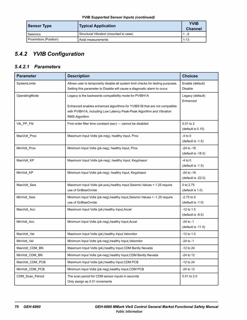
YVIB Supported Sensor Inputs (continued)
Sensor Type Typical Application YVIBChannel
Seismics Structural Vibration (mounted to case) 1 - 8Proximitors (Position) Axial measurements 1-13
5.4.2 YVIB Configuration
5.4.2.1 Parameters
Parameter Description ChoicesSystemLimits Allows user to temporarily disable all system limit checks for testing purposes.
Setting this parameter to Disable will cause a diagnostic alarm to occur.Enable (default)Disable
OperatingMode Legacy is the backwards compatibility mode for PVIBH1A
Enhanced enables enhanced algorithms for YVIBS1B that are not compatiblewith PVIBH1A, including Low Latency Peak-Peak Algorithm and VibrationRMS Algorithm
Legacy (default)Enhanced
Vib_PP_Fltr First order filter time constant (sec) — cannot be disabled 0.01 to 2(default is 0.10)
MaxVolt_Prox Maximum Input Volts (pk-neg), healthy Input, Prox -4 to 0(default is -1.5)
MinVolt_Prox Minimum Input Volts (pk-neg), healthy Input, Prox -24 to -16(default is -18.5)
MaxVolt_KP Maximum Input Volts (pk-neg), healthy Input, Keyphasor -4 to 0(default is -1.5)
MinVolt_KP Minimum Input Volts (pk-neg), healthy Input, Keyphasor -24 to -16(default is -22.0)
MaxVolt_Seis Maximum Input Volts (pk-pos),healthy Input,Seismic:Values > 1.25 requireuse of GnBiasOvride
0 to 2.75(default is 1.0)
MinVolt_Seis Minimum Input Volts (pk-neg),healthy Input,Seismic:Values < -1.25 requireuse of GnBiasOvride
-2.75 to 0(default is -1.0)
MaxVolt_Acc Maximum Input Volts (pk),healthy Input,Accel -12 to 1.5(default is -8.5)
MinVolt_Acc Minimum Input Volts (pk-neg),healthy Input,Accel -24 to -1(default is -11.5)
MaxVolt_Vel Maximum Input Volts (pk),healthy Input,Velomitor -12 to 1.5
MinVolt_Vel Minimum Input Volts (pk-neg),healthy Input,Velomitor -24 to -1
MaxVolt_CDM_BN Maximum Input Volts (pk),healthy Input,CDM Bently Nevada -12 to 24
MinVolt_CDM_BN Minimum Input Volts (pk-neg),healthy Input,CDM Bently Nevada -24 to 12
MaxVolt_CDM_PCB Maximum Input Volts (pk),healthy Input,CDM PCB -12 to 24
MinVolt_CDM_PCB Minimum Input Volts (pk-neg),healthy Input,CDM PCB -24 to 12
CDM_Scan_Period The scan period for CDM sensor inputs in secondsOnly assign as 0.01 increments
0.01 to 2.0
70 GEH-6860 GEH-6860 MMark VIeS Control General Market Functional Safety ManualPublic Information

5.4.2.2 Variables
Variables Description Direction andDatatype
L3DIAG_xxxx_x I/O Pack Diagnostic Indicator where Pxxx or Yxxx is the name of the I/O pack and R, S, orT is the redundancy of pack
Input BOOL
LINK_OK_xxxx_x IONet Link Okay Indicator where Pxxx or Yxxx is the name of the I/O pack and R, S, or Tis the redundancy
Input BOOL
ATTN_xxxx_x I/O Pack Status Indicator where Pxxx or Yxxx is the name of the I/O pack and R, S, or T isthe redundancy
Input BOOL
PS18V_xxxx_x I/O Pack 18 V Power Supply Indication where Pxxx or Yxxx is the name of the I/O packand R, S, or T is the redundancy
Input BOOL
PS28V_xxxx_x I/O Pack 28 V Power Supply Indication where Pxxx or Yxxx is the name of the I/O packand R, S, or T is the redundancy
Input BOOL
IOPackTmpr_ I/O Pack Temperature at the processor where R, S, or T is the redundancy Input BOOL
RPM_KPH1 Speed (RPM)of KP#1,calculated from input#13 Analog Input REAL
RPM_KPH2 Speed (RPM)of KP#2,calculated from input#12 (PVIBH1B only) Analog Input REAL
LM_RPM_A Speed A(RPM), calculated externally to the I/O Pack Analog Output REAL
LM_RPM_B Speed B(RPM), calculated externally to the I/O Pack Analog Output REAL
LM_RPM_C Speed C(RPM), calculated externally to the I/O Pack Analog Output REAL
SysLim1GAPx
where x = 1 to 13
Boolean set TRUE if System Limit 1 exceeded for Gap x input Input BOOL
SysLim2GAPx
where x = 1 to 13
Boolean set TRUE if System Limit 2 exceeded for Gap x input Input BOOL
SysLim1VIBx
where x = 1 to 8
Boolean set TRUE if System Limit 1 exceeded for Vib x input Input BOOL
SysLim2VIBx
where x = 1 to 8
Boolean set TRUE if System Limit 2 exceeded for Vib x input Input BOOL
SysLim1ACCx
where x = 1 to 9
Boolean set TRUE if System Limit 1 exceeded for Accelerometer x input Input BOOL
SysLim2ACCx
where x = 1 to 9
Boolean set TRUE if System Limit 2 exceeded for Accelerometer x input Input BOOL
I/O Configuration GEH-6860 Functional Safety Manual 71Public Information

5.4.2.3 Probe Nominal Settings
Probe Type Gain † Snsr_Offset (Vdc) Scale (typical value)Proximity 1x 9 200 mv/mil
Seismic 4x 0 150 mv/ips
Velomitor 2x 12 100 mv/ips
Accelerometer 2x 10 150 mv/ips
Keyphasor 1x 9 200 mv/mil
Bently Nevada CDM 2x 10 170 mv/psi
PCB CDM 2x -12 170 mv/psi
†These are the default settings used if GnBiasOvride=Disable.
5.4.2.4 LM 1–3[ ] = defaults
Name Direction DataType
Description TMR_DiffLimit SysLim1E-nabl
SysLim1-Latch
SysLimit1Type SysLimit1
LMVib#A
AnalogInput REAL
Magnitude of1X harmonicrelative toLM_RPM_A,B, or Ccalculatedfrom input#1,2, or 3 (9 totalinputs)
DifferenceLimit for VotedTMR Inputs inVolts or Mils[2]-100 to 100
EnableSystem Limit 1[Disable],Enable
Latch thealarm[Latch],NotLatch
System Limit 1Check Type[ >= ] , <=
System Limit1 – Vibrationin mils (prox)or Inch/sec(seismic,acel)[50]-100 to 100
↓
LMVib#C
SysLim2Enabl SysLim2Latch SysLim2Type SysLimit2
Enable SystemLimit 2[Disable],Enable
Latch the alarm[Latch],NotLatch
System Limit 2Check Type[ >= ] , <=
System Limit 2 –Vibration in mils(prox) or Inch/sec(seismic,acel)[0]-100 to 100
5.4.2.5 Vib1x 1-8
Name Direction Data Type Description
VIB_1X1 AnalogInput REAL Magnitude of 1X harmonic relative to key phasor speed calculated from input#1
↓ ↓ ↓ ↓
VIB_1X8 AnalogInput REAL Magnitude of 1X harmonic relative to key phasor speed calculated from input#8
Vib1xPH1 AnalogInput REAL Angle of 1X harmonic relative to key phasor calculated from input#1
↓ ↓ ↓ ↓
Vib1xPH8 AnalogInput REAL Angle of 1X harmonic relative to key phasor calculated from input#8
72 GEH-6860 GEH-6860 MMark VIeS Control General Market Functional Safety ManualPublic Information
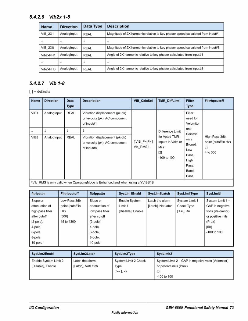
5.4.2.6 Vib2x 1-8
Name Direction Data Type DescriptionVIB_2X1 AnalogInput REAL Magnitude of 2X harmonic relative to key phasor speed calculated from input#1
↓ ↓ ↓ ↓
VIB_2X8 AnalogInput REAL Magnitude of 2X harmonic relative to key phasor speed calculated from input#8
Vib2xPH1 AnalogInput REAL Angle of 2X harmonic relative to key phasor calculated from input#1
↓ ↓ ↓ ↓
Vib2xPH8 AnalogInput REAL Angle of 2X harmonic relative to key phasor calculated from input#8
5.4.2.7 Vib 1-8[ ] = defaults
Name Direction DataType
Description VIB_CalcSel TMR_DiffLimt FilterType
Filtrhpcutoff
VIB1 AnalogInput REAL Vibration displacement (pk-pk)or velocity (pk), AC componentof input#1
[ VIB_Pk-Pk ]Vib_RMS ‡
Difference Limitfor Voted TMRInputs in Volts orMils[2]-100 to 100
Filterused forVelomitorandSeismiconly[None],LowPass,HighPass,BandPass
High Pass 3dbpoint (cutoff in Hz)[6]4 to 300
↓ ↓ ↓ ↓
VIB8 AnalogInput REAL Vibration displacement (pk-pk)or velocity (pk), AC componentof input#8
‡Vib_RMS is only valid when OperatingMode is Enhanced and when using a YVIBS1B
fltrlpattn Filtrlpcutoff fltrlppattn SysLim1Enabl SysLim1Latch SysLim1Type SysLimit1
Slope orattenuation ofhigh pass filterafter cutoff[2-pole],4-pole,6-pole,8-pole,10-pole
Low Pass 3dbpoint (cutoff inHz)[500]15 to 4300
Slope orattenuation oflow pass filterafter cutoff[2-pole]4-pole,6-pole,8-pole,10-pole
Enable SystemLimit 1[Disable], Enable
Latch the alarm[Latch], NotLatch
System Limit 1Check Type[ >= ], <=
System Limit 1 –GAP in negativevolts (Velomitor)or positive mils(Prox)[50]-100 to 100
SysLim2Enabl SysLim2Latch SysLim2Type SysLimit2
Enable System Limit 2[Disable], Enable
Latch the alarm[Latch], NotLatch
System Limit 2 CheckType[ >= ], <=
System Limit 2 – GAP in negative volts (Velomitor)or positive mils (Prox)[0]-100 to 100
I/O Configuration GEH-6860 Functional Safety Manual 73Public Information

5.4.2.8 Gap 1-3[ ] = defaults† only valid with YVIBS1B‡ LM Tracking Filter magnitude value may be inaccurate at 160, 320 ms frame periods.
Name Direction DataType
Description VIB_Type4 Scale Scale_Off TMR_DiffLimit
GAP1_VIB1 AnalogIn-put
REAL Average Air Gap (for Prox) or DCvolts(for others),DC component ofinput#1
Type of vibrationprobe, group 4†CDM_BN_ChgAmp,†CDM_PCB_ChgAmp,PosProx,[Unused],‡VibLMAccel,VibProx,VibProx-KPH1,VibProx-KPH2,VibSeismic,VibVelomitor
Volts/-mil orVolt-s/ips[0.2]0 to 2
Scaleoffset forProxpositiononly, inmils[0]0 to 90
DifferenceLimit for VotedTMR Inputs inVolts or Mils[2]-100 to 100
GAP2_VIB2 AnalogIn-put
REAL Average Air Gap (for Prox) or DCvolts(for others),DC component ofinput#2
GAP3_VIB3 AnalogIn-put
REAL Average Air Gap (for Prox) or DCvolts(for others),DC component ofinput#3
GnBiasOvride Snsr_Offset Gain LMlpcutoff SysLim1Enabl SysLim1Latch SysLim1Type SysLimit1
Gain BiasOverride[Disable],Enable
Amount of bias voltage(dc) to remove frominput signal used tomax. A/Ds signal rangeused only whenGnBiasOvride isenabled[10]±13.5
Resolution ofinput signal(net gainunchanged),select basedon expectedrange, useonly ifGnBiasOvrideis enabled[1x], 2x, 4x, 8x
Low pass3dB point(cutoff Hz)for LMtrackingfilters1.5Hz,2.0Hz,[2.5Hz],3.0Hz,3.5Hz,4.0Hz,4.5Hz,5.0Hz
Enable SystemLimit 1[Disable],Enable
Latch thealarm[Latch],NotLatch
System Limit 1Check Type[ >= ] , <=
SystemLimit 1 –GAP innegativevolts(Velomitor)or positivemils (Prox)[90]-100 to100
SysLim2Enabl SysLim2Latch SysLim2Type SysLimit2 CDM_Probe_Gain CDM_Amp_Gain
Enable System Limit2[Disable], Enable
Latch the alarm[Latch], NotLatch
System Limit 2Check Type[ >= ] , <=
System Limit 2 –GAP in negativevolts (Velomitor) orpositive mils (Prox)[10]-100 to 100
PCB Probe Gain,pico-coulombs perpsi[17]1 to 100
PCB Chargeamplifier Gain,millivolts perpico-coulomb[10]1 to 100
74 GEH-6860 GEH-6860 MMark VIeS Control General Market Functional Safety ManualPublic Information
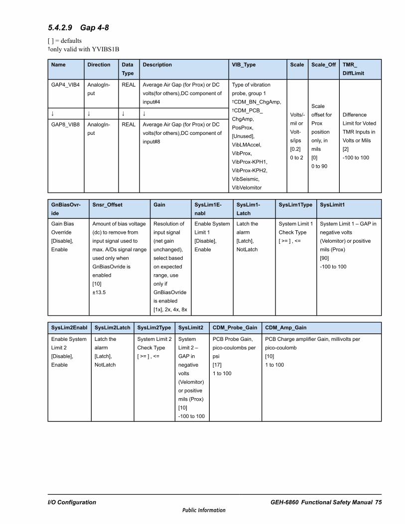
5.4.2.9 Gap 4-8[ ] = defaults†only valid with YVIBS1B
Name Direction DataType
Description VIB_Type Scale Scale_Off TMR_DiffLimit
GAP4_VIB4 AnalogIn-put
REAL Average Air Gap (for Prox) or DCvolts(for others),DC component ofinput#4
Type of vibrationprobe, group 1†CDM_BN_ChgAmp,†CDM_PCB_ChgAmp,PosProx,[Unused],VibLMAccel,VibProx,VibProx-KPH1,VibProx-KPH2,VibSeismic,VibVelomitor
Volts/-mil orVolt-s/ips[0.2]0 to 2
Scaleoffset forProxpositiononly, inmils[0]0 to 90
DifferenceLimit for VotedTMR Inputs inVolts or Mils[2]-100 to 100
↓ ↓ ↓ ↓
GAP8_VIB8 AnalogIn-put
REAL Average Air Gap (for Prox) or DCvolts(for others),DC component ofinput#8
GnBiasOvr-ide
Snsr_Offset Gain SysLim1E-nabl
SysLim1-Latch
SysLim1Type SysLimit1
Gain BiasOverride[Disable],Enable
Amount of bias voltage(dc) to remove frominput signal used tomax. A/Ds signal rangeused only whenGnBiasOvride isenabled[10]±13.5
Resolution ofinput signal(net gainunchanged),select basedon expectedrange, useonly ifGnBiasOvrideis enabled[1x], 2x, 4x, 8x
Enable SystemLimit 1[Disable],Enable
Latch thealarm[Latch],NotLatch
System Limit 1Check Type[ >= ] , <=
System Limit 1 – GAP innegative volts(Velomitor) or positivemils (Prox)[90]-100 to 100
SysLim2Enabl SysLim2Latch SysLim2Type SysLimit2 CDM_Probe_Gain CDM_Amp_Gain
Enable SystemLimit 2[Disable],Enable
Latch thealarm[Latch],NotLatch
System Limit 2Check Type[ >= ] , <=
SystemLimit 2 –GAP innegativevolts(Velomitor)or positivemils (Prox)[10]-100 to 100
PCB Probe Gain,pico-coulombs perpsi[17]1 to 100
PCB Charge amplifier Gain, millivolts perpico-coulomb[10]1 to 100
I/O Configuration GEH-6860 Functional Safety Manual 75Public Information

5.4.2.10 Gap 9-11[ ] = defaults
Name Direction DataType
Description VIB_Type2 Scale Scale_Off TMR_DiffLimit
GAP9_POS1 AnalogInput REAL Average Air Gap,DCcomponent of input#9 Sensor Type, group
2[Unused],PosProx
Volts/milorVolts/ips[0.2]0 to 2
Scale offsetfor Proxpositiononly, in mils[0]0 to 90
DifferenceLimit for VotedTMR Inputs inVolts or Mils[2]-100 to 100
GAP10_POS2 AnalogInput REAL Average Air Gap,DCcomponent of input#10
GAP11_POS3 AnalogInput REAL Average Air Gap,DCcomponent of input#11
GnBiasOvride Snsr_Offset Gain SysLim1Enabl SysLim1Latch SysLim1Type SysLimit1
Gain BiasOverride[Disable], Enable
Amount of biasvoltage (dc) toremove frominput signal usedto max. A/Dssignal rangeused only whenGnBiasOvride isenabled[10]±13.5
Resolution ofinput signal (netgain unchanged),select based onexpected range,use only ifGnBiasOvride isenabled[1x], 2x, 4x, 8x
Enable SystemLimit 1[Disable], Enable
Latch the alarm[Latch], NotLatch
System Limit 1Check Type[ >= ] , <=
System Limit 1 –GAP in negativevolts (Velomitor)or positive mils(Prox)[90]-100 to 100
SysLim2Enabl SysLim2Latch SysLim2Type SysLimit2
Enable System Limit 2[Disable], Enable
Latch the alarm[Latch], NotLatch
System Limit 2 Check Type[ >= ] , <=
System Limit 2 – GAP innegative volts (Velomitor) orpositive mils (Prox)[10]-100 to 100
76 GEH-6860 GEH-6860 MMark VIeS Control General Market Functional Safety ManualPublic Information

5.4.2.11 KPH[ ] = defaults† only valid with YVIBS1B
Name Direction DataType
Description VIB_Type3 Scale Scale_Off TMR_DiffLimit
KPH_Thrshld
GAP12_KPH2 AnalogInput REAL Average Air Gap,DCcomponent of input#9
Sensor Type,group 3[Unused],PosProx, †
KeyPhasor
Volts/-mil orVolt-s/ips[0.2]0 to 2
Scaleoffset forProxpositiononly, inmils[0]0 to 90
DifferenceLimit for VotedTMR Inputs inVolts or Mils[2]-100 to 100
Voltagedifference fromgap voltagewherekeyphasortriggers[2.0]1.0 to 5.0
GAP13_KPH1 AnalogInput REAL Average Air Gap,DCcomponent ofinput#10
Sensor Type,group 3[Unused],PosProx,KeyPhasor
KPH_Type GnBiasOvr-ide
Snsr_Offset Gain SysLim1E-nabl
SysLim1-Latch
SysLim1Type SysLimit1
[Slot],Pedestal
Gain BiasOverride[Disable],Enable
Amount of biasvoltage (dc) toremove from inputsignal used tomax. A/Ds signalrange used onlywhenGnBiasOvride isenabled[10]±13.5
Resolution ofinput signal(net gainunchanged),select basedon expectedrange, useonly ifGnBiasOvrideis enabled[1x], ‡ 2x, 4x, ‡
8x
Enable SystemLimit 1[Disable],Enable
Latch thealarm[Latch],NotLatch
System Limit 1Check Type[ >= ] , <=
SystemLimit 1 –GAP innegativevolts(Velomitor)or positivemils (Prox)[90]-100 to 100
‡Gain 2x and Gain 8x are Never valid on GAP12_KPH2.
SysLim2Enabl SysLim2Latch SysLim2Type SysLimit2
Enable System Limit 2[Disable], Enable
Latch the alarm[Latch], NotLatch
System Limit 2 Check Type[ >= ] , <=
System Limit 2 – GAP innegative volts (Velomitor) orpositive mils (Prox)[10]-100 to 100
I/O Configuration GEH-6860 Functional Safety Manual 77Public Information
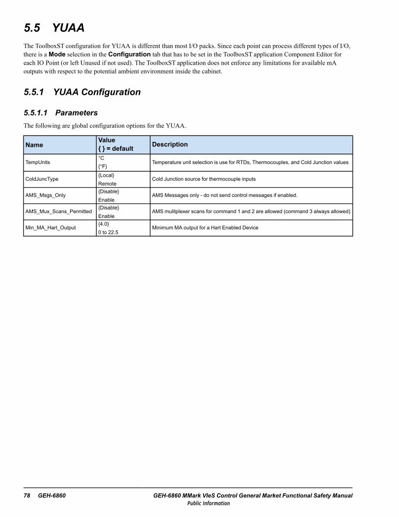
5.5 YUAAThe ToolboxST configuration for YUAA is different than most I/O packs. Since each point can process different types of I/O,there is a Mode selection in the Configuration tab that has to be set in the ToolboxST application Component Editor foreach IO Point (or left Unused if not used). The ToolboxST application does not enforce any limitations for available mAoutputs with respect to the potential ambient environment inside the cabinet.
5.5.1 YUAA Configuration
5.5.1.1 ParametersThe following are global configuration options for the YUAA.
NameValue = default Description
TempUnits°C°F
Temperature unit selection is use for RTDs, Thermocouples, and Cold Junction values
ColdJuncTypeLocalRemote
Cold Junction source for thermocouple inputs
AMS_Msgs_OnlyDisableEnable
AMS Messages only - do not send control messages if enabled.
AMS_Mux_Scans_PermittedDisableEnable
AMS mulitplexer scans for command 1 and 2 are allowed (command 3 always allowed)
Min_MA_Hart_Output4.00 to 22.5
Minimum MA output for a Hart Enabled Device
78 GEH-6860 GEH-6860 MMark VIeS Control General Market Functional Safety ManualPublic Information
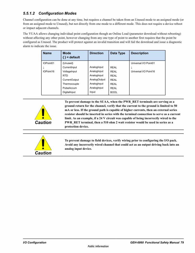
5.5.1.2 Configuration ModesChannel configuration can be done at any time, but requires a channel be taken from an Unused mode to an assigned mode (orfrom an assigned mode to Unused), but not directly from one mode to a different mode. This does not require a device rebootor impact adjacent channels.
The YUAA allows changing individual point configuration though an Online Load (parameter download without rebooting)without affecting any other point, however changing from any one type of point to another first requires that the point beconfigured as Unused. The product will protect against an invalid transition and will fail the download and issue a diagnosticalarm to indicate the issue.
Name Mode = default
Direction Data Type Description
IOPoint01↓IOPoint16
UnusedCurrentInputVoltageInputRTDCurrentOutputThermocouplePulseAccumDigitalInput
AnalogInputAnalogInputAnalogInputAnalogOutputAnalogInputAnalogInputInput
REALREALREALREALREALREALBOOL
Universal I/O Point01↓Universal I/O Point16
Caution
To prevent damage to the SUAA, when the PWR_RET terminals are serving as aground return for the channel, verify that the current to the ground is limited to 50mA or less. If the ground path is capable of higher currents, then an external seriesresistor should be inserted in series with the terminal connection to serve as a currentlimit. As an example, if a 24 V circuit was capable of being incorrectly wired to thePWR_RET terminal, then a 510 ohm 2 watt resistor would be used in series as aprotection device.
Caution
To prevent damage to field devices, verify wiring prior to configuring the I/O pack.Avoid any incorrectly wired channel that could act as an output driving back into ananalog input device.
I/O Configuration GEH-6860 Functional Safety Manual 79Public Information
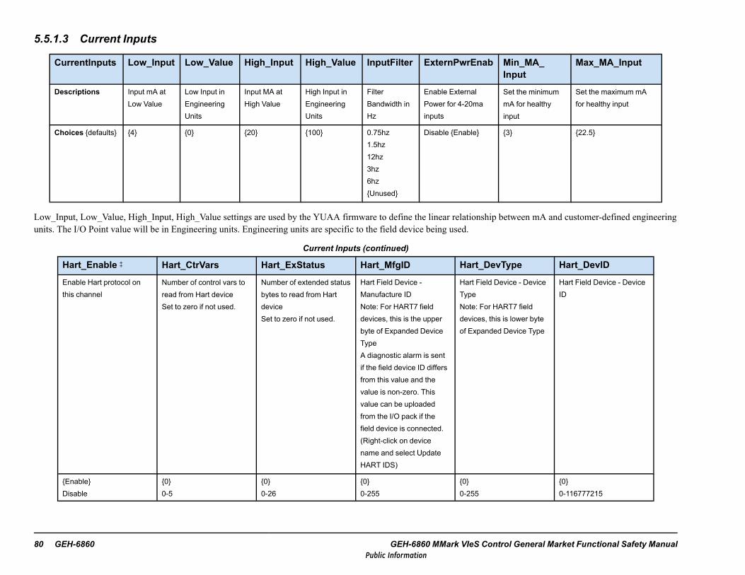
5.5.1.3 Current Inputs
CurrentInputs Low_Input Low_Value High_Input High_Value InputFilter ExternPwrEnab Min_MA_Input
Max_MA_Input
Descriptions Input mA atLow Value
Low Input inEngineeringUnits
Input MA atHigh Value
High Input inEngineeringUnits
FilterBandwidth inHz
Enable ExternalPower for 4-20mainputs
Set the minimummA for healthyinput
Set the maximum mAfor healthy input
Choices defaults 4 0 20 100 0.75hz1.5hz12hz3hz6hzUnused
Disable Enable 3 22.5
Low_Input, Low_Value, High_Input, High_Value settings are used by the YUAA firmware to define the linear relationship between mA and customer-defined engineeringunits. The I/O Point value will be in Engineering units. Engineering units are specific to the field device being used.
Current Inputs (continued)
Hart_Enable ‡ Hart_CtrVars Hart_ExStatus Hart_MfgID Hart_DevType Hart_DevID
Enable Hart protocol onthis channel
Number of control vars toread from Hart deviceSet to zero if not used.
Number of extended statusbytes to read from HartdeviceSet to zero if not used.
Hart Field Device -Manufacture IDNote: For HART7 fielddevices, this is the upperbyte of Expanded DeviceTypeA diagnostic alarm is sentif the field device ID differsfrom this value and thevalue is non-zero. Thisvalue can be uploadedfrom the I/O pack if thefield device is connected.(Right-click on devicename and select UpdateHART IDS)
Hart Field Device - DeviceTypeNote: For HART7 fielddevices, this is lower byteof Expanded Device Type
Hart Field Device - DeviceID
EnableDisable
00-5
00-26
00-255
00-255
00-116777215
80 GEH-6860 GEH-6860 MMark VIeS Control General Market Functional Safety ManualPublic Information
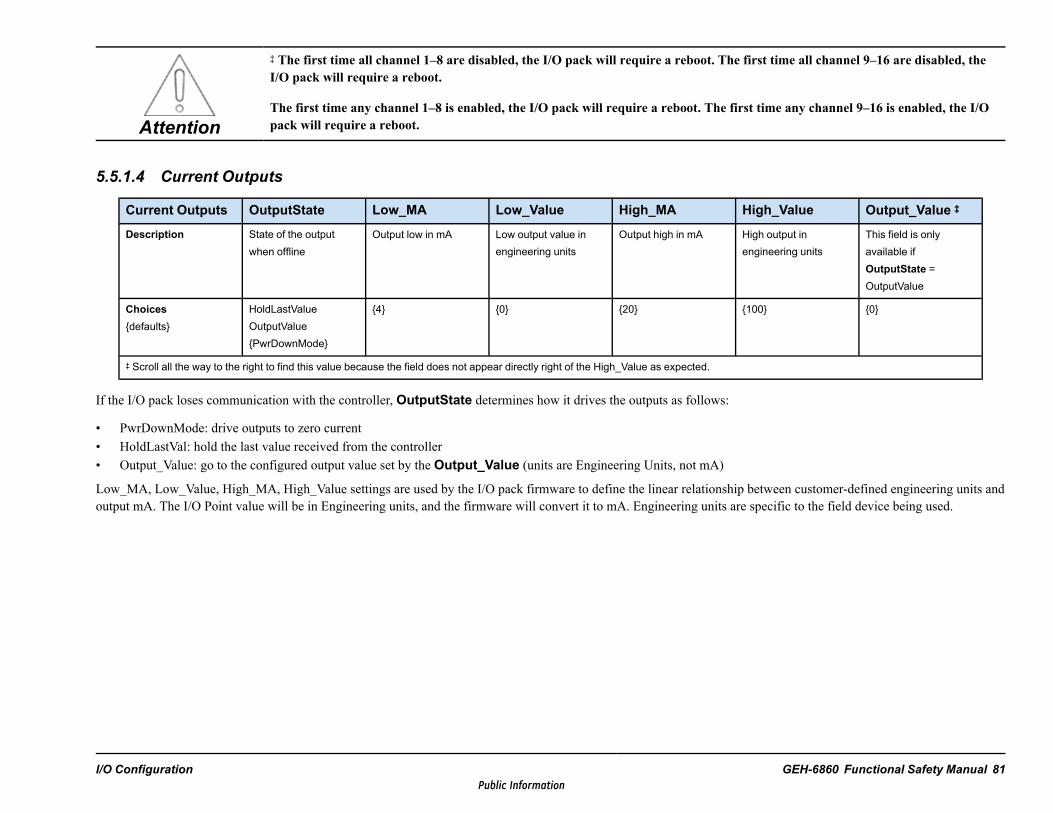
Attention
‡ The first time all channel 1–8 are disabled, the I/O pack will require a reboot. The first time all channel 9–16 are disabled, theI/O pack will require a reboot.
The first time any channel 1–8 is enabled, the I/O pack will require a reboot. The first time any channel 9–16 is enabled, the I/Opack will require a reboot.
5.5.1.4 Current Outputs
Current Outputs OutputState Low_MA Low_Value High_MA High_Value Output_Value ‡
Description State of the outputwhen offline
Output low in mA Low output value inengineering units
Output high in mA High output inengineering units
This field is onlyavailable ifOutputState =OutputValue
Choicesdefaults
HoldLastValueOutputValuePwrDownMode
4 0 20 100 0
‡ Scroll all the way to the right to find this value because the field does not appear directly right of the High_Value as expected.
If the I/O pack loses communication with the controller, OutputState determines how it drives the outputs as follows:
• PwrDownMode: drive outputs to zero current• HoldLastVal: hold the last value received from the controller• Output_Value: go to the configured output value set by the Output_Value (units are Engineering Units, not mA)
Low_MA, Low_Value, High_MA, High_Value settings are used by the I/O pack firmware to define the linear relationship between customer-defined engineering units andoutput mA. The I/O Point value will be in Engineering units, and the firmware will convert it to mA. Engineering units are specific to the field device being used.
I/O Configuration GEH-6860 Functional Safety Manual 81Public Information

Current Outputs (continued)
Hart_Enable ‡ Hart_CtrVars Hart_ExStatus Hart_MfgID Hart_DevType Hart_DevID
Enable Hart protocol onthis channel
Number of control vars toread from Hart deviceSet to zero if not used.
Number of extended statusbytes to read from HartdeviceSet to zero if not used.
Hart Field Device -Manufacture IDNote: For HART7 fielddevices, this is the upperbyte of Expanded DeviceTypeA diagnostic alarm is sentif the field device ID differsfrom this value and thevalue is non-zero. Thisvalue can be uploadedfrom the I/O pack if thefield device is connected.(Right-click on devicename and select UpdateHART IDS)
Hart Field Device - DeviceTypeNote: For HART7 fielddevices, this is lower byteof Expanded Device Type
Hart Field Device - DeviceID
DisableEnable
00-5
00-26
00-255
00-255
00-116777215
Attention
‡ The first time any channel 1–8 is enabled, the I/O pack will require a reboot. The first time any channel 9–16 is enabled, the I/Opack will require a reboot.
The first time all channel 1–8 are disabled, the I/O pack will require a reboot. The first time all channel 9–16 are disabled, theI/O pack will require a reboot.
82 GEH-6860 GEH-6860 MMark VIeS Control General Market Functional Safety ManualPublic Information
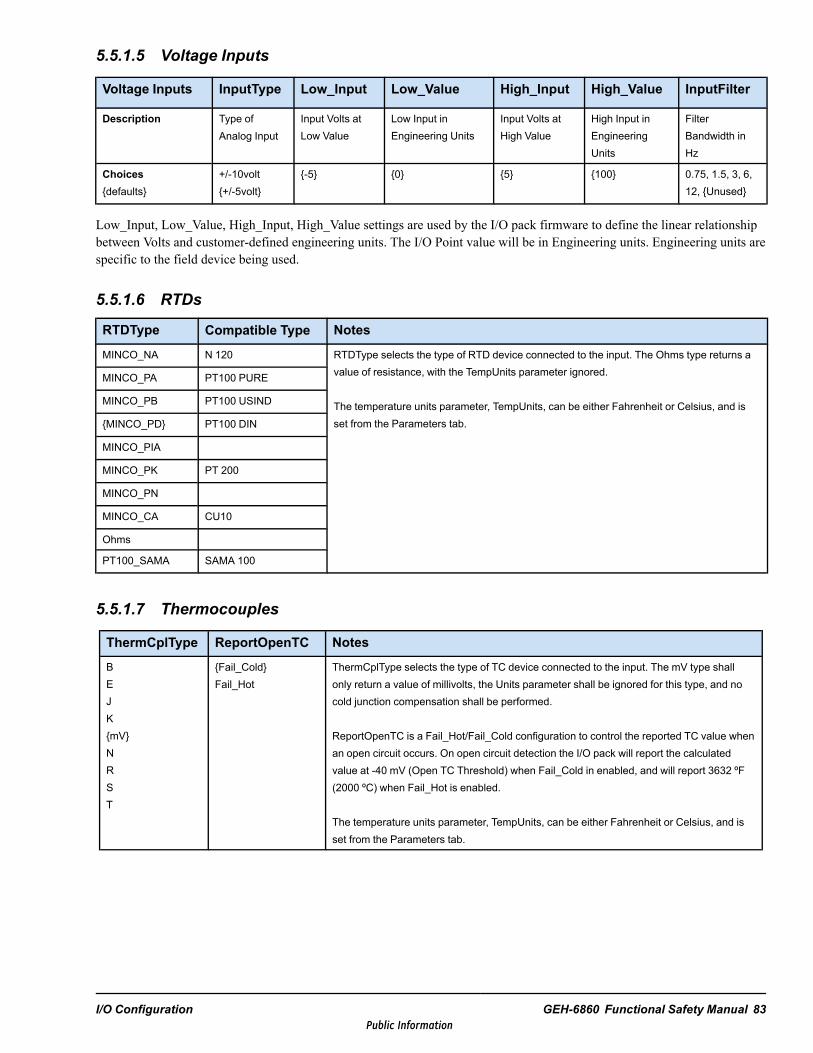
5.5.1.5 Voltage Inputs
Voltage Inputs InputType Low_Input Low_Value High_Input High_Value InputFilter
Description Type ofAnalog Input
Input Volts atLow Value
Low Input inEngineering Units
Input Volts atHigh Value
High Input inEngineeringUnits
FilterBandwidth inHz
Choicesdefaults
+/-10volt+/-5volt
-5 0 5 100 0.75, 1.5, 3, 6,12, Unused
Low_Input, Low_Value, High_Input, High_Value settings are used by the I/O pack firmware to define the linear relationshipbetween Volts and customer-defined engineering units. The I/O Point value will be in Engineering units. Engineering units arespecific to the field device being used.
5.5.1.6 RTDs
RTDType Compatible Type Notes
MINCO_NA N 120 RTDType selects the type of RTD device connected to the input. The Ohms type returns avalue of resistance, with the TempUnits parameter ignored.
The temperature units parameter, TempUnits, can be either Fahrenheit or Celsius, and isset from the Parameters tab.
MINCO_PA PT100 PURE
MINCO_PB PT100 USIND
MINCO_PD PT100 DIN
MINCO_PIA
MINCO_PK PT 200
MINCO_PN
MINCO_CA CU10
Ohms
PT100_SAMA SAMA 100
5.5.1.7 Thermocouples
ThermCplType ReportOpenTC Notes
BEJKmVNRST
Fail_ColdFail_Hot
ThermCplType selects the type of TC device connected to the input. The mV type shallonly return a value of millivolts, the Units parameter shall be ignored for this type, and nocold junction compensation shall be performed.
ReportOpenTC is a Fail_Hot/Fail_Cold configuration to control the reported TC value whenan open circuit occurs. On open circuit detection the I/O pack will report the calculatedvalue at -40 mV (Open TC Threshold) when Fail_Cold in enabled, and will report 3632 ºF(2000 ºC) when Fail_Hot is enabled.
The temperature units parameter, TempUnits, can be either Fahrenheit or Celsius, and isset from the Parameters tab.
I/O Configuration GEH-6860 Functional Safety Manual 83Public Information
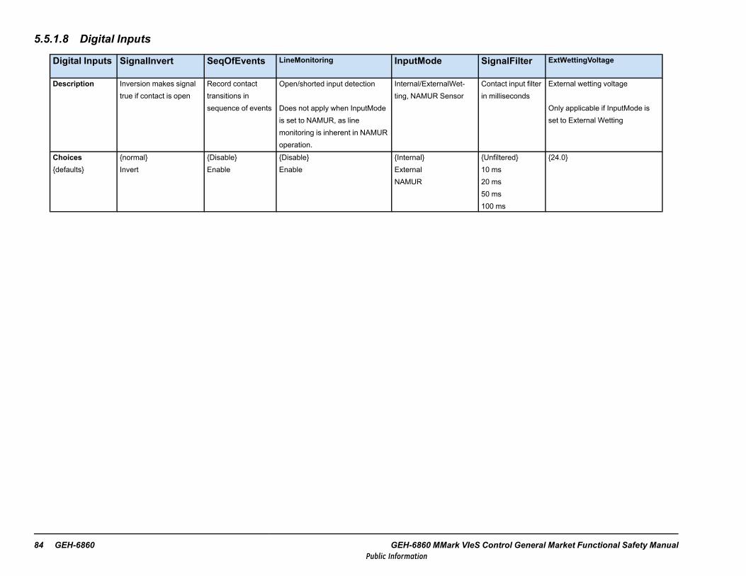
5.5.1.8 Digital Inputs
Digital Inputs SignalInvert SeqOfEvents LineMonitoring InputMode SignalFilter ExtWettingVoltage
Description Inversion makes signaltrue if contact is open
Record contacttransitions insequence of events
Open/shorted input detection
Does not apply when InputModeis set to NAMUR, as linemonitoring is inherent in NAMURoperation.
Internal/ExternalWet-ting, NAMUR Sensor
Contact input filterin milliseconds
External wetting voltage
Only applicable if InputMode isset to External Wetting
Choicesdefaults
normalInvert
DisableEnable
DisableEnable
InternalExternalNAMUR
Unfiltered10 ms20 ms50 ms100 ms
24.0
84 GEH-6860 GEH-6860 MMark VIeS Control General Market Functional Safety ManualPublic Information
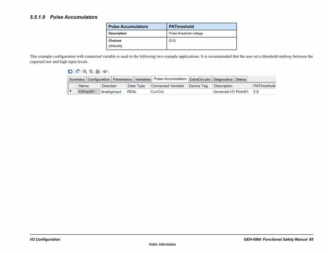
5.5.1.9 Pulse Accumulators
Pulse Accumulators PAThresholdDescription Pulse threshold voltage
Choicesdefaults
3.0
This example configuration with connected variable is used in the following two example applications. It is recommended that the user set a threshold midway between theexpected low and high input levels.
I/O Configuration GEH-6860 Functional Safety Manual 85Public Information

5.5.1.10 Pulse Accumulator Buffer ExampleThis user block example connects to YUAA pulse accumulator inputs to provide a Total Counts output that is a 32-bit integer.It handles YUAA 16-bit rollovers and implements a user reset of total counts to zero. The 16-bit accumulator resets to zerowhen the I/O pack reboots or the channel’s mode is changed. The counter increments when the input voltage transitions abovethe PAThreshold setting. The next pulse after accumulator is at 65535 will result in the accumulator rolling over to zero andcontinuing to count from there on following pulses.
86 GEH-6860 GEH-6860 MMark VIeS Control General Market Functional Safety ManualPublic Information

5.5.1.11 Frequency Calculation ExampleThis user block example connects to YUAA pulse accumulator inputs to provide a frequency output. Rollover is handled. Three configuration values are offered.
I/O Configuration GEH-6860 Functional Safety Manual 87Public Information

88 GEH-6860 GEH-6860 MMark VIeS Control General Market Functional Safety ManualPublic Information

5.5.1.12 Variables
Name Direction Data Type Description
L3DIAG_YUAA_R Input BOOL I/O Diagnostic Indication
LINK_OK_YUAA_R Input BOOL I/O Link Okay Indication
ATTN_YUAA_R Input BOOL I/O Attention Indication
OutxxMA AnalogInput REAL Current Output Feedback in mA, where xx = the channel number
PS18V_YUAA_R Input BOOL I/O 18V Power Supply Indication
PS28V_YUAA_R Input BOOL I/O 28V Power Supply Indication
IOPackTmpr_R AnalogInput REAL IO Pack Temperature (deg F)
CJBackup AnalogOutput REAL Backup Cold Junction Temperature (Deg F/C based on Cold Junction config)
CJRemote AnalogOutput REAL Remote Cold Junction Temperature. Used when ColdJuncType is set to Remote(Deg F/C based on Cold Junction config)
ColdJunc01 AnalogInput REAL Cold Junction sensor #1
ColdJunc02 AnalogInput REAL Cold Junction sensor #2
AckHartCfgChange Output BOOL Toggle to True to reset Hart configuration change alarms on rising edge
HartMux_Health Input BOOL Hart Mux Health
5.5.1.13 HART Signal Definitions
Signal Type Description
Hxx_CommCnt IntegerNumber of times the CommStat signal was not zero after a HARTmessage
Hxx_CommStat Bit encoded integer
Most Recent Slave-Reported Communication Status ErrorBit 1 – RX buffer overflowBit 3 – Checksum errorBit 4 – Framing error Bit 5 – Overrun error Bit 6 – Parity error
Hxx_DevCnt IntegerNumber of times the DevStat signal was not zero after a HARTmessage.
Hxx_DevStat Bit encoded integer
Most Recent Device Response Codes: bits 0-7Bit 0 – Primary variable out of limits Bit 1 – Non primary var out oflimits Bit 2 – Analog output saturatedBit 3 – Analog output current fixedBit 4 – More status available (ExStat) Bit 5 – Cold startBit 6 – Configuration changed Bit 7 – Field device malfunctionCommand response byte: bits 8-152: Invalid selection requested3: Passed parameter too large4: Passed parameter too small5: Too few bytes received6: Device specific device error7: In write protect mode8-15: Device specific16: Access restricted32: Device is busy64: Command not implemented
Hxx_DevRev Integer Field Device - Device revision code as read from the device.
I/O Configuration GEH-6860 Functional Safety Manual 89Public Information

Signal Type Description
Hxx_HwSwRev IntegerByte 0 - Field device software revisionByte 1 - Field device hardware revision
Hxx_mA † Float Field Parm 1 – current reading of the primary signalHxx_PV † Float Field Device Specific Control Parm 2 - Primary field device valueHxx_SV † Float Field Device Specific Control Parm 3 - Secondary valueHxx_TV † Float Field Device Specific Control Parm 4 -Third valueHxx_FV † Float Field Device Specific Control Parm 5 -Fourth value† To view these variables, the Hart_CtrlVars parameter must have a value greater than zero.
5.5.1.14 HART Extended StatusThe extended status bits are device-specific, and can be interrogated by using an AMS system. In general, the status bits aregrouped as follows:
• Bytes 0-5: Device specific status• Byte 6: Extended Device Status• Byte 7: Device Operating Mode• Byte 8: Standardize Status 0• Byte 9: Standardize Status 1• Byte 10: Analog Channel Saturated• Byte 11: Standardize Status 2• Byte 12: Standardize Status 3• Byte 13: Analog Channel Fixed• Bytes 14-26: Device-specific
Each field device supports a specific number of control parameters and extended status bits. Refer to the Field Devicedocumentation to determine the correct number and configure the ToolboxST application accordingly. A diagnostic alarmmessage will be generated if the Field Device and ToolboxST configuration do not match.
Hxx_ExStat_1 Bit Encoded Extended Status Bytes 1-4Hxx_ExStat_2 Bit Encoded Extended Status Bytes 5-8Hxx_ExStat_3 Bit Encoded Extended Status Bytes 9-12Hxx_ExStat_4 Bit Encoded Extended Status Bytes 13-16Hxx_ExStat_5 Bit Encoded Extended Status Bytes 17-20Hxx_ExStat_6 Bit Encoded Extended Status Bytes 21-24Hxx_ExStat_7 Bit Encoded Extended Status Bytes 25-26
90 GEH-6860 GEH-6860 MMark VIeS Control General Market Functional Safety ManualPublic Information

6 Proof TestsCertain periodic proof tests must be satisfied for IEC-61511 SIL certification eligibility. The testing schedule and resourcesare dependent on the designated proof test interval.
This test plan is to be used to validate SIL requirements for the Mark VIeS Functional Safety System during proof testing.Proof tests shall be conducted periodically to reveal any faults that may be undetected by system diagnostics during normaloperation.
This test plan provides the following:
• Identifies the nature and extent of tests necessary to verify that the Mark VIeS Functional Safety System is fullycompliant with SIL requirements
• Identifies equipment and describes test methodologies used to provide proof test coverage
Adhere to the following guidelines before and during proof tests:
• All test equipment must have up-to-date calibrations. Record the make, model, serial numbers, and calibration dates inthe test record. The accuracy of measuring devices adds to the acceptance criteria.
• Where possible, replace the terminal board field-wired terminal block with a test block to preserve field wiring withminimum disturbance.
• Only test inputs or outputs of any Mark VIeS Functional Safety System I/O packs that are connected and used. UnusedI/O do not have to be proof tested.
• Only apply the specific proof test that is appropriate for the I/O pack channel configuration. For example, only apply thethermocouple proof test for the YUAA I/O channel that is configured as a thermocouple.
• These test procedures do not require configuration modifications to an existing SIS. The system configurations that arelisted are suggested configurations for test purposes. If the configuration does not match the system under test, either thetest does not apply or the test results need to be adjusted.
• Before each proof test:− Verify that no diagnostic alarms are present.− Bypass any safety loop being tested or take other action to avoid an inadvertent trip.− Check for inadvertent or unauthorized application changes by checking the Branding Code and compare to the
application code recorded after commissioning or after the last authorized and verified change. Verify that theBranding Code matches the application code.
The following table lists the pluggable connectors that are available for order to facilitate proof tests.
Available Pluggable Connectors
Pluggable Connector Part Number
Phoenix 2, 3, 4, 6, 8, and 12screw-pluggable connectors
PDJF1000TBPLUG#(where # is 3, 4, 6, 8 or 12 to identify number of screws the user wants thepluggable connector to have)
24 point (screw) isolated-barrier blackterminal block
173C9123BB 003
Proof Tests GEH-6860 Functional Safety Manual 91Public Information
6.1 Proof Test Requirements
6.1.1 Dual and TMR System Test RequirementsDual and TMR system configurations have automatic voting comparison diagnostics that provide random failure detection. Iffield device test procedures have met the following test requirements, and the alarm system has been checked to verify that nocomparison diagnostics have been generated by the test, the system and the voting diagnostics can be tested using the fielddevice test procedures provided in this document. Additionally, when power (or the communications cable) is removed fromone I/O pack in a hardware fault tolerant channel for each safety loop, the comparison diagnostic will indicate a fault. Whenpower exceeding the hardware fault tolerance is removed from the I/O packs), the system fails to its configured Safe state.
YAIC: Each analog sensor should be separately tested, one sensor at a time. Each test, if practicable, should range the sensorbeyond the normal range of operation within the upper and lower limits of the sensors detectable range. Each output is testedwhen the output is ranged through a full range transition required to test the field device. When power (or the communicationscable) is removed from one I/O pack in a hardware fault tolerant channel, the system should maintain the required output.
YDIA: Each sensor causing a logical transition on the controller should be tested.
YDOA: Stimulate the safety function such that the output makes a transition. When power (or the communications cable) isremoved from one I/O pack in a hardware fault tolerant channel, the system should maintain the required output. Any outputfailures generate an error indication.
YUAA: Each configurable mode should be separately tested: mA input or output, TC input, RTD input and discrete input.Each mA input, if possible, should range the sensor beyond the normal range of operation within the upper and lower limits ofthe sensors detectable range. Each mA output should be tested when the output is ranged through the full range transitionrequired to test the field device. Open thermocouple / RTD detection can be tested by disconnecting one lead perthermocouple / RTD at the terminal board screws. Each discrete input should be tested, resulting in a logical transition, pluscheck for proper detection of open and shorted field wiring.
YVIB: Each sensor connected to an input should be separately tested, one sensor at a time (VibProx, VibProx-KPH,VibSiesmic, PosProx). Each test (if practicable) should range the sensor beyond the normal range of operation within theupper and lower limits of the sensors detectable range. Key Phasor* input accuracy can be tested in place if a reference speedis available to compare. When power (or the communications cable) is removed from one I/O pack in a hardware faulttolerant channel, the system should maintain the required output.
6.1.2 Simplex System Test RequirementsSimplex systems do not benefit from having comparison diagnostics between the redundant controllers. Therefore, functionaltesting is the most effective way to detect random failures within the controller.
92 GEH-6860 GEH-6860 MMark VIeS Control General Market Functional Safety ManualPublic Information

6.2 YAIC Test Procedures
6.2.1 Input AccuracyTest Overview:
• Test the accuracy of the YAIC analog inputs for the configured I/O pack• Test out of range detection for the configured I/O pack
Note Only test channels used and enabled for the assigned configuration.
Test Setup:
1. Obtain a multi-meter and a signal source capable of generating current and voltages within the ranges of the configuredYAIC I/O pack.
2. Confirm configured limits for 4-20 mA input types. If configured for ranges other than 4-20 mA, adjust the test limitsaccordingly.
Note Channels 9 and 10 only allow current input; do not test input voltage on these channels.
A set of test values are provided in the following table. Use only those test values associated with the configured I/O point.Configuration changes are not required.
Test Steps:
• For the configured I/O, select the appropriate test values from the following table, Test Values for Configuration Settings,and apply them to the input.
• Document the value that the YAIC reads for each test value, as seen in the Input tab in the ToolboxST application.• Perform these test steps for each configured input channel.
Acceptance Criteria:
• All measured values must be within 2% of the full range input values for the input accuracy test to be accepted.• For out of range values using the ToolboxST application, confirm that the YAIC alerts the system that the input is out of
range through the Diagnostics tab and that the channel goes unhealthy.
Proof Tests GEH-6860 Functional Safety Manual 93Public Information
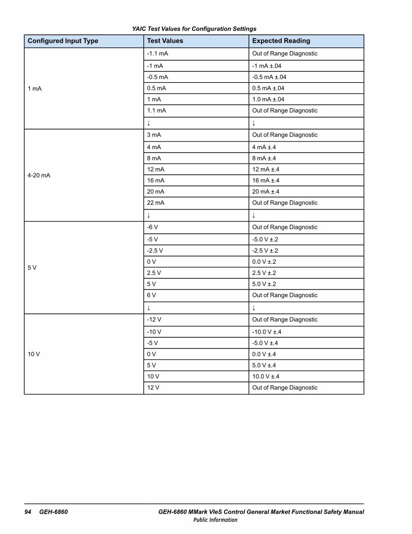
YAIC Test Values for Configuration Settings
Configured Input Type Test Values Expected Reading
1 mA
-1.1 mA Out of Range Diagnostic
-1 mA -1 mA ±.04
-0.5 mA -0.5 mA ±.04
0.5 mA 0.5 mA ±.04
1 mA 1.0 mA ±.04
1.1 mA Out of Range Diagnostic
↓ ↓
4-20 mA
3 mA Out of Range Diagnostic
4 mA 4 mA ±.4
8 mA 8 mA ±.4
12 mA 12 mA ±.4
16 mA 16 mA ±.4
20 mA 20 mA ±.4
22 mA Out of Range Diagnostic
↓ ↓
5 V
-6 V Out of Range Diagnostic
-5 V -5.0 V ±.2
-2.5 V -2.5 V ±.2
0 V 0.0 V ±.2
2.5 V 2.5 V ±.2
5 V 5.0 V ±.2
6 V Out of Range Diagnostic
↓ ↓
10 V
-12 V Out of Range Diagnostic
-10 V -10.0 V ±.4
-5 V -5.0 V ±.4
0 V 0.0 V ±.4
5 V 5.0 V ±.4
10 V 10.0 V ±.4
12 V Out of Range Diagnostic
94 GEH-6860 GEH-6860 MMark VIeS Control General Market Functional Safety ManualPublic Information

6.2.2 Output AccuracyTest Overview:
To test the accuracy of the YAIC I/O pack analog outputs for the configured I/O packs.
Test Setup:
1. Connect a multi-meter to the configured mA outputs.
2. Add a load to the output of approximately 250 Ω or meter in line with actual load device.
Test Steps:
1. Connect the first channel of the output of the YAIC pack to a multi-meter capable of measuring voltage and current.
2. Set the output of the pack to the first value in the following table. To set the output, go to the Output tab in theToolboxST application and change the value of AnalogOutputxx.
3. Record the measured output current (mA) reading for this channel and output level.
4. Repeat steps 2 and 3 for each value in the following table.
5. Repeat steps 1-4 above for all channels configured for mA outputs.
Acceptance Criteria:
All measured values must be within 2% of the expected output values for the accuracy test to be accepted.
Output Ranges to Test
Output Value Expected Value Observed Reading
0 mA 0 mA ±.4
4 mA 4 mA ±.4
8 mA 8 mA ±.4
12 mA 12 mA ±.4
16 mA 16 mA ±.4
20 mA 20 mA ±.4
Proof Tests GEH-6860 Functional Safety Manual 95Public Information

6.2.3 Low Source VoltageTest Overview:
The common source voltage for the analog input loop voltages for two-wire transmitters is monitored to detect low loopvoltage and provide fault tolerance for this function when more than one I/O processor is present.
Test Setup:
1. Prepare the system for a fail-safe response from the I/O pack.
2. Connect a multi-meter to any configured mA outputs of the I/O pack from the Output Accuracy test.
Test Steps:
1. Disconnect the 28 V power supply connection from the I/O pack. For a TMR terminal board, disconnect the powersupply from two I/O packs.
2. Confirm that all the inputs go unhealthy and that the outputs drop to 0 mA.
Acceptance Criteria:
With the I/O pack’s power removed, the inputs become Unhealthy and drop any configured output channels to 0 mA current.
96 GEH-6860 GEH-6860 MMark VIeS Control General Market Functional Safety ManualPublic Information

6.3 YDIATest ProceduresItems that are configurable in the YDIA pack are identified in this test plan by including (CFG) at the end of the name of theitem. Any configurable items that must be set for a particular test are defined in the detailed test instructions below. If asetting is not given for a configurable item, then it is not relevant to that test.
Unless otherwise noted in the test plan, the tester should verify that there are no diagnostics faults on the YDIA pack undertest prior to performing each test case.
Any diagnostic fault(s) that are expected to occur as a result of performing a test case will be detailed in the acceptancecriteria for the test case.
If additional diagnostics faults are generated in the course of testing that are not detailed in the acceptance criteria, they mustbe fully explained prior to acceptance of the test.
The following tests can be performed in any order. Individual steps within a test should be performed in the order presented.
6.3.1 Digital Input StatusTest Overview:
The test verifies that the controllers can receive the input data. This tests the following items that are configurable on eachdigital input using the ToolboxST application:
• ContactInput(CFG) (Used/Unused)• SignalInvert(CFG) (Normal/Invert)• DiagVoteEnab(CFG) (Enable/Disable)
Test Setup:
Perform the applicable test case (refer to the following sections) on each of the inputs as they are configured. Check if a testscrew terminal is available to avoid de-wiring a field signal.
Test Steps:
Test Case 1: Test Input Used, Normal
1. Verify that all inputs are as follows:
• ContactInput(CFG) = Used• SignalInvert(CFG) = Normal• DiagVoteEnab(CFG) = Enable
2. With Input X open, verify that all three controllers indicate the status of the input as False.
3. Connect a jumper between Input X (Positive) and Input X (Return).
4. Verify that each controller (R, S, T) correctly reads the status of Input X as True.
5. Check that there is no cross-interference by verifying that the status of all other inputs is False.
6. Repeat this procedure for the remaining inputs.
Acceptance Criteria:
• Inputs are jumpered and all three controllers indicate the status as True.• All inputs not jumpered have a status of False.• There are no voting diagnostics.
Proof Tests GEH-6860 Functional Safety Manual 97Public Information

Test Case 2: Test Input Used, Invert
1. Verify that all inputs that are as follows:
• ContactInput(CFG) = Used• SignalInvert(CFG) = Invert• DiagVoteEnab(CFG) = Enable
2. With Input X open, verify that all three controllers indicate the status of the input as True.
3. Connect a jumper between Input X (Positive) and Input X (Return).
4. Verify that each controller (R, S, T) correctly reads the status of Input X as False.
5. Check that there is no cross-interference by verifying that the status of all other inputs is True.
6. Repeat this procedure for the remaining inputs.
Acceptance Criteria:
• Inputs are jumpered and all three controllers indicate the status as False.• All inputs not jumpered have a status of True.• There are no voting diagnostics.
6.3.2 Low Source VoltageTest Overview:
This test verifies that YDIA:
• Monitors its 28 V dc supply• Generates diagnostics if the supply is out of limits• Performs an orderly shutdown if power supply voltage is too low for safe operation
Test Setup:
Prepare the system for a fail-safe response from the I/O pack.
Test Steps:
1. Disconnect the 28 V dc power supply connection from the I/O pack. In a TMR system, disconnect the power connectionfrom two I/O packs.
2. Confirm that all the inputs go unhealthy.
3. For loss of power on one I/O pack of TMR, check for disagreement diagnostic.
Acceptance Criteria:
When the I/O pack is disconnected, a diagnostic is generated and all inputs display as Unhealthy.
98 GEH-6860 GEH-6860 MMark VIeS Control General Market Functional Safety ManualPublic Information

6.4 YDOATest ProceduresItems that are configurable in the YDOA pack are identified by including (CFG) at the end of the name of the item. Anyconfigurable items that must be set for a particular test are defined in the detailed test instructions below. If a setting is notgiven for a configurable item, then it is not relevant to that test.
Unless otherwise noted in the test plan, the tester should verify that there are no diagnostics faults on the YDOA pack undertest prior to performing each test case.
Any diagnostic fault(s) that are expected to occur as a result of performing a test case will be detailed in the acceptancecriteria for the test case.
If additional diagnostics faults are generated in the course of testing that are not detailed in the acceptance criteria, they mustbe fully explained prior to acceptance of the test.
The following tests can be performed in any order. Individual steps within a test should be performed in the order presented.
6.4.1 Digital Output ControlTest Overview:
This functional test verifies that:
• The Safety controller can control each output• The outputs are controlled through fault tolerant voting in TMR system• There is no cross-interference between outputs
Note This test is relevant to all terminal board types.
Note Tests should be performed based on the configuration of each of the outputs.
Relay actuation can be detected as follows:
1. If the device controlled by the relay is safe to actuate, it may be used to determine the relay output state.
2. With wetting voltage applied, the voltage at the relay terminal board may be read.When the YDOA is mounted on a TRLY, two pluggable terminal blocks used:
− 173C9123BB 003 (24-point pluggable terminal block, 1-24)− 173C9123BB 004 (24-point pluggable terminal block, 25-48)
When the YDOA is mounted on an SRLY (Simplex configuration), one pluggable terminal block is used: 64G6940-224L(48-point pluggable terminal block, 1-48).
3. Remove any wetting voltage and read the relay contact path resistance.
Note For methods two and three, GE recommends removing the terminal board screw blocks and replacing them with testblocks.
For method three, GE recommends taking a voltage reading prior to the resistance reading for safety purposes.
Test Setup:
Perform the appropriate test based on configuration of each of the outputs.
Proof Tests GEH-6860 Functional Safety Manual 99Public Information

Test Case 1: Test Output Used, Normal
1. Verify that each output is as follows:
• RelayOutput(CFG) = Used• SignalInvert(CFG) = Normal
2. Verify that all outputs are initially turned off.
3. Turn on the relay output.
4. Verify that only the correct relay on the terminal board is energized.
5. Repeat this procedure for all configured relay outputs.
Acceptance Criteria:
With the output turned on in the controller, only the correct relay on the terminal board is energized.
Test Case 2: Test Output Used, Invert
1. Verify that each output is as follows:
• RelayOutput(CFG) = Used• SignalInvert(CFG) = Invert
2. All outputs should initially be turned on.
3. Turn off the output.
4. Verify that only the correct relay on the terminal board is energized.
5. Repeat for all configured relay outputs
Acceptance Criteria:
With the output turned off in the controller, only the correct relay on the terminal board is energized.
100 GEH-6860 GEH-6860 MMark VIeS Control General Market Functional Safety ManualPublic Information

6.4.2 Energized to Trip Applications
6.4.2.1 Relay Diagnostics for TRLYS1DTest Overview:
This test verifies that the I/O pack:
• Reads feedback signals from the output circuits• Verifies that the outputs are in the correct state• Generates diagnostic messages if they are not in the correct state
Test Setup:
This test is to be performed on the TRLYS1D, and either 24 or 125 V dc.
Test Steps:
Test Case 1: Solenoid Integrity on TRLYS1D with 24 V DC
Note Perform this test on all configured outputs.
1. Using a YDOA/TRLYS1D combination, connect 24 V dc power to connector JF1 on the terminal board with configureoutputs:
• RelayOutput(CFG) = Used• SignalInvert(CFG) = Normal
2. Connect a 0-250 Ω potentiometer across the NO and SOL terminals for the input under test; set the wiper to the middle oftravel. All outputs should initially be turned off.
3. Gradually decrease the potentiometer resistance until a diagnostic is generated indicating that there is a failure of theexternal solenoid.
4. Disconnect the potentiometer and measure the resistance.
5. Reset the wiper of the potentiometer to the middle of travel and reconnect it to the terminals for the output under test.
6. Gradually increase the potentiometer resistance until a diagnostic indicates an external solenoid failure.
7. Disconnect the potentiometer and measure the resistance.
Acceptance Criteria:
The output is de-energized and the external resistance is:
• Below 7 Ω, a diagnostic is generated to indicate solenoid failure• Above 200 Ω, a diagnostic is generated to indicate solenoid failure
Proof Tests GEH-6860 Functional Safety Manual 101Public Information
Test Case 2: Solenoid Integrity on TRLYS1D with 125 V DC
Note Perform this test on all configured outputs.
1. Connect 125 V dc power to connector JF1 on the terminal board with configure outputs:
• RelayOutput(CFG) = Used• SignalInvert(CFG) = Normal
2. Connect a 0–5000 Ω potentiometer across the NO and SOL terminals for the input under test. Set the wiper to the middleof travel. All outputs should initially be turned off.
3. Gradually decrease the potentiometer resistance until a diagnostic indicates an external solenoid failure.
4. Disconnect the potentiometer and measure the resistance.
5. Reset the potentiometer wiper to the middle of travel and reconnect it to the terminals for the output under test.
6. Gradually increase the potentiometer resistance until a diagnostic indicates an external solenoid failure.
7. Disconnect the potentiometer and measure the resistance.
Acceptance Criteria:
The output is de-energized and the external resistance is:
• Below 122 Ω, a diagnostic is generated to indicate solenoid failure• Above 3250 Ω, a diagnostic is generated to indicate solenoid failure
6.4.3 Low Source VoltageTest Overview:
This test verifies that the I/O pack:
• Monitors its 28 V dc supply• Generates diagnostics if the supply is out of limits• Performs an orderly shutdown if the power supply voltage is too low for safe operation
Test Setup:
Prepare system for a fail-safe response from the I/O pack.
Test Steps:
1. Disconnect the 28 V power supply connection from the I/O pack. For TMR, disconnect 28 V power supply connectionsfrom two I/O packs.
2. Confirm that all the outputs go to their safe state, displays as Unhealthy, and a diagnostic is generated.
Acceptance Criteria:
When the I/O pack is disconnected, a diagnostic is generated and all inputs display as Unhealthy.
102 GEH-6860 GEH-6860 MMark VIeS Control General Market Functional Safety ManualPublic Information

6.5 YUAATest Procedures
6.5.1 mA / Voltage Input AccuracyTest Overview:
• Test the accuracy of the YUAA mA / voltage-configured inputs of the I/O pack• Test out of range detection for the configured I/O pack
ToolboxST Parameters:
• Configuration Tab: Mode(CFG) (Unused, CurrentInput, VoltageInput, RTD, CurrentOutput, Thermocouple,PulseAccum, DigitalInput)
• Current Inputs Tab: Low_Input(CFG) (<value>)• Current Inputs Tab: High_Input(CFG) (<value>)• Current Inputs Tab: Low_Value(CFG) (<value>)• Current Inputs Tab: High_Value(CFG) (<value>)• Current Inputs Tab: Min_MA_Input(CFG) (<value>)• Current Inputs Tab: Max_MA_Input(CFG) (<value>)• Configuration Tab: Mode(CFG) (Unused, CurrentInput, VoltageInput, RTD, CurrentOutput, Thermocouple,
PulseAccum, DigitalInput)• Voltage Inputs Tab: Input Type(CFG) (±5 V, =/-10 V)• Voltage Inputs Tab: Low_Input(CFG) (<value>)• Voltage Inputs Tab: High_Input(CFG) (<value>)• Voltage Inputs Tab: Low_Value(CFG) (<value>)• Voltage Inputs Tab: High_Value(CFG) (<value>)
Test Setup:
1. Obtain a multi-meter and a signal source capable of generating current and voltages within the ranges of the configuredYUAA I/O pack.
2. Refer to the table Test Values for Configuration Settings for a set of test values. Use only the test values associated withthe configured I/O point. Configuration changes are not required.
Test Steps:
• For the configured I/O, select the appropriate test values from the table Test Values for Configuration Settings and applythem to the input.
• Document the value that the YUAA reads for each test value, as displayed in the Current Inputs or Voltage Inputstab in the ToolboxST application. The following acceptance criteria provides the calculations needed to assess acceptedresults.
• Perform these test steps for each configured input channel.
Proof Tests GEH-6860 Functional Safety Manual 103Public Information

Acceptance Criteria:
• All measured values must be within 0.2% of the full range input values for the input accuracy test to be accepted.Perform the following steps to make this determination:
1. Capture the configured scaling parameter values Low_Input, High_Input, Low_Value, High_Value for the I/O point to betested. Use the following calculations to compute the Expected Value in Engineering Units, based upon the applied Test_Input in mA or V:
2. Use the following calculation to determine the deviation range:
3. Acceptable measured values for each Test Input must fall within the range Expected_Value ± Deviation, per the formulasabove.
• For out of range values, use the ToolboxST application to confirm that the YUAA alerts the system that the input isout of range through the Diagnostics tab, and that the channel goes Unhealthy.
Test Values for Configuration Settings
Configured Input Type Test Inputs Expected Reading
4-20 mA
3 mA Out of Range Diagnostic8 mA Expected_Value ± Deviation12 mA Expected_Value ± Deviation16 mA Expected_Value ± Deviation22 mA Out of Range Diagnostic↓ ↓
5 V
-6 V Out of Range Diagnostic-2.5 V Expected_Value ± Deviation0 V Expected_Value ± Deviation2.5 V Expected_Value ± Deviation6 V Out of Range Diagnostic↓ ↓
10 V
-12 V Out of Range Diagnostic-6 V Expected_Value ± Deviation0 V Expected_Value ± Deviation6 V Expected_Value ± Deviation12 V Out of Range Diagnostic
104 GEH-6860 GEH-6860 MMark VIeS Control General Market Functional Safety ManualPublic Information
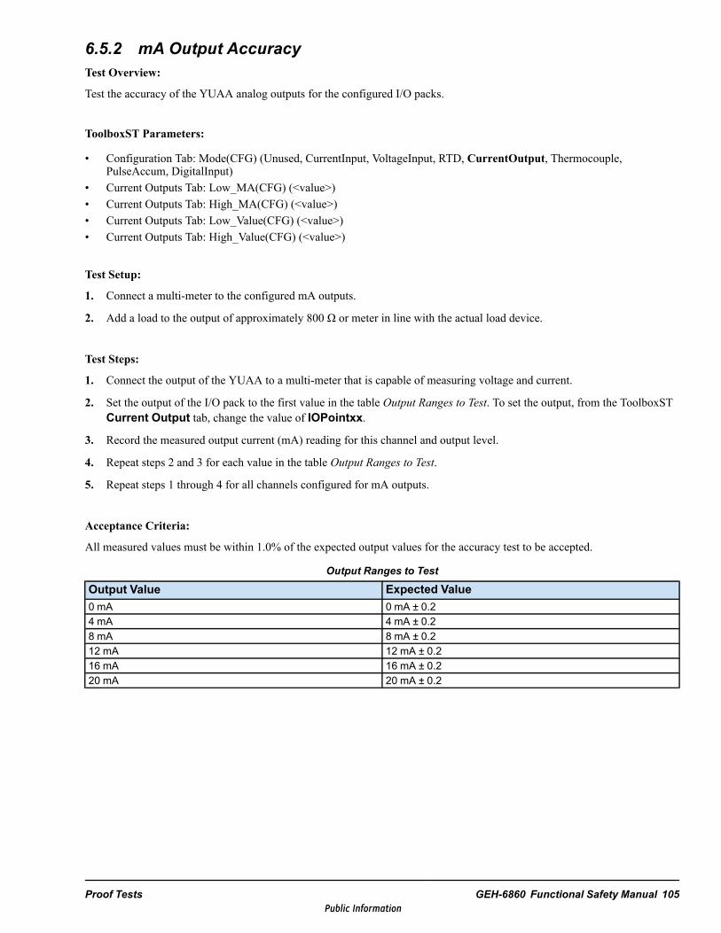
6.5.2 mA Output AccuracyTest Overview:
Test the accuracy of the YUAA analog outputs for the configured I/O packs.
ToolboxST Parameters:
• Configuration Tab: Mode(CFG) (Unused, CurrentInput, VoltageInput, RTD, CurrentOutput, Thermocouple,PulseAccum, DigitalInput)
• Current Outputs Tab: Low_MA(CFG) (<value>)• Current Outputs Tab: High_MA(CFG) (<value>)• Current Outputs Tab: Low_Value(CFG) (<value>)• Current Outputs Tab: High_Value(CFG) (<value>)
Test Setup:
1. Connect a multi-meter to the configured mA outputs.
2. Add a load to the output of approximately 800 Ω or meter in line with the actual load device.
Test Steps:
1. Connect the output of the YUAA to a multi-meter that is capable of measuring voltage and current.
2. Set the output of the I/O pack to the first value in the table Output Ranges to Test. To set the output, from the ToolboxSTCurrent Output tab, change the value of IOPointxx.
3. Record the measured output current (mA) reading for this channel and output level.
4. Repeat steps 2 and 3 for each value in the table Output Ranges to Test.
5. Repeat steps 1 through 4 for all channels configured for mA outputs.
Acceptance Criteria:
All measured values must be within 1.0% of the expected output values for the accuracy test to be accepted.
Output Ranges to Test
Output Value Expected Value0 mA 0 mA ± 0.24 mA 4 mA ± 0.28 mA 8 mA ± 0.212 mA 12 mA ± 0.216 mA 16 mA ± 0.220 mA 20 mA ± 0.2
Proof Tests GEH-6860 Functional Safety Manual 105Public Information

6.5.3 Thermocouple Input AccuracyWhen two or more thermocouples are in near proximity to each other and are expected to measure the same ambienttemperature, an alternative test can be performed to record and compare the temperature profile as the thermocouples coolfrom operational temperature and converge to the same ambient temperature. This alternative test may take several hours forambient temperature to stabilize.
Test Overview:
Test the accuracy of the YUAA I/O pack for various thermocouple configurations.
ToolboxST Parameters:
• Configuration Tab: Mode(CFG) (Unused, CurrentInput, VoltageInput, RTD, CurrentOutput, Thermocouple,PulseAccum, DigitalInput)
• Thermocouples Tab: ThermCplType(CFG) (mV, B, E, J, K, N, R, S, T)• Thermocouples Tab: ReportOpenTC(CFG) (Fail_Cold, Fail_Hot)
Test Setup:
Obtain a mV signal source that is capable of fractional mV signals.
Alternative:
Use a calibrated heat source or thermocouple test set.
Test Steps:
1. For the configured thermocouple, select the applicable thermocouple type from one of the following tables: Type BThermocouples, Type E Thermocouples, Type J Thermocouples, Type K Thermocouples, Type N Thermocouples, Type RThermocouples, Type S Thermocouples, or Type T Thermocouples.
2. From the ToolboxST Variables tab, read the temperature for the variables ColdJunc01 and ColdJunc02 and average thereadings from the two inputs.
3. Look up the equivalent mV reading for the cold junction temperature in the Cold Junction Compensation column of theapplicable Thermocouples table. Some interpolation is required.
4. Select one of the mV values in the applicable Thermocouples table and inject a mV signal such that the sum of the coldjunction mV values and the injected mV signal at the terminal board input equals one of the mV values in the mV columnof the thermocouple table. The temperature reading displayed in ToolboxST for that thermocouple reading should beequal to the temperature in the table.
5. Repeat step 4 for a second mV value in the applicable Thermocouple table.
For example, for a type E thermocouple with a cold junction reading of 25°C (76.9 °F), the test steps would be as follows:
1. In the table Type E Thermocouples, for 25°C (76.9 °F) the cold junction mV compensation is 1.49 mV.
2. Select 10 mVas a thermocouple test value.
3. Inject a mV signal of (10.0 – 1.5) = 8.5 mVat the terminal board screws.
4. The thermocouple should read 152.8 ± -15 °C (307 ± 5 °F).
Acceptance Criteria:
All measured temperature signals should be within ± -15°C (5 °F) of the expected temperature for the input accuracy test tobe accepted.
106 GEH-6860 GEH-6860 MMark VIeS Control General Market Functional Safety ManualPublic Information
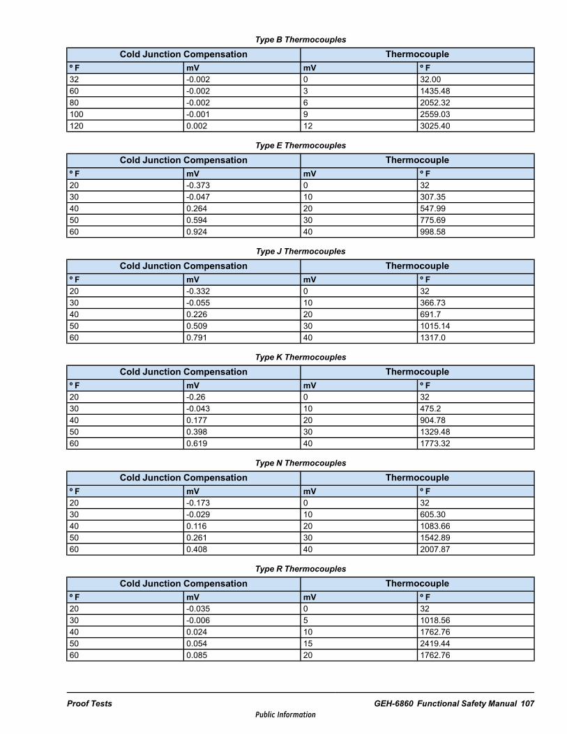
Type B Thermocouples
Cold Junction Compensation Thermocoupleº F mV mV º F32 -0.002 0 32.0060 -0.002 3 1435.4880 -0.002 6 2052.32100 -0.001 9 2559.03120 0.002 12 3025.40
Type E Thermocouples
Cold Junction Compensation Thermocoupleº F mV mV º F20 -0.373 0 3230 -0.047 10 307.3540 0.264 20 547.9950 0.594 30 775.6960 0.924 40 998.58
Type J Thermocouples
Cold Junction Compensation Thermocoupleº F mV mV º F20 -0.332 0 3230 -0.055 10 366.7340 0.226 20 691.750 0.509 30 1015.1460 0.791 40 1317.0
Type K Thermocouples
Cold Junction Compensation Thermocoupleº F mV mV º F20 -0.26 0 3230 -0.043 10 475.240 0.177 20 904.7850 0.398 30 1329.4860 0.619 40 1773.32
Type N Thermocouples
Cold Junction Compensation Thermocoupleº F mV mV º F20 -0.173 0 3230 -0.029 10 605.3040 0.116 20 1083.6650 0.261 30 1542.8960 0.408 40 2007.87
Type R Thermocouples
Cold Junction Compensation Thermocoupleº F mV mV º F20 -0.035 0 3230 -0.006 5 1018.5640 0.024 10 1762.7650 0.054 15 2419.4460 0.085 20 1762.76
Proof Tests GEH-6860 Functional Safety Manual 107Public Information
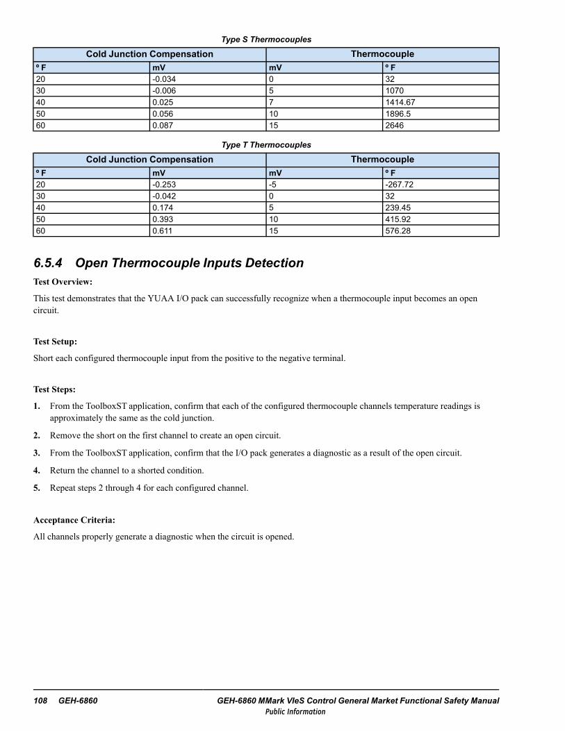
Type S Thermocouples
Cold Junction Compensation Thermocoupleº F mV mV º F20 -0.034 0 3230 -0.006 5 107040 0.025 7 1414.6750 0.056 10 1896.560 0.087 15 2646
Type T Thermocouples
Cold Junction Compensation Thermocoupleº F mV mV º F20 -0.253 -5 -267.7230 -0.042 0 3240 0.174 5 239.4550 0.393 10 415.9260 0.611 15 576.28
6.5.4 Open Thermocouple Inputs DetectionTest Overview:
This test demonstrates that the YUAA I/O pack can successfully recognize when a thermocouple input becomes an opencircuit.
Test Setup:
Short each configured thermocouple input from the positive to the negative terminal.
Test Steps:
1. From the ToolboxST application, confirm that each of the configured thermocouple channels temperature readings isapproximately the same as the cold junction.
2. Remove the short on the first channel to create an open circuit.
3. From the ToolboxST application, confirm that the I/O pack generates a diagnostic as a result of the open circuit.
4. Return the channel to a shorted condition.
5. Repeat steps 2 through 4 for each configured channel.
Acceptance Criteria:
All channels properly generate a diagnostic when the circuit is opened.
108 GEH-6860 GEH-6860 MMark VIeS Control General Market Functional Safety ManualPublic Information
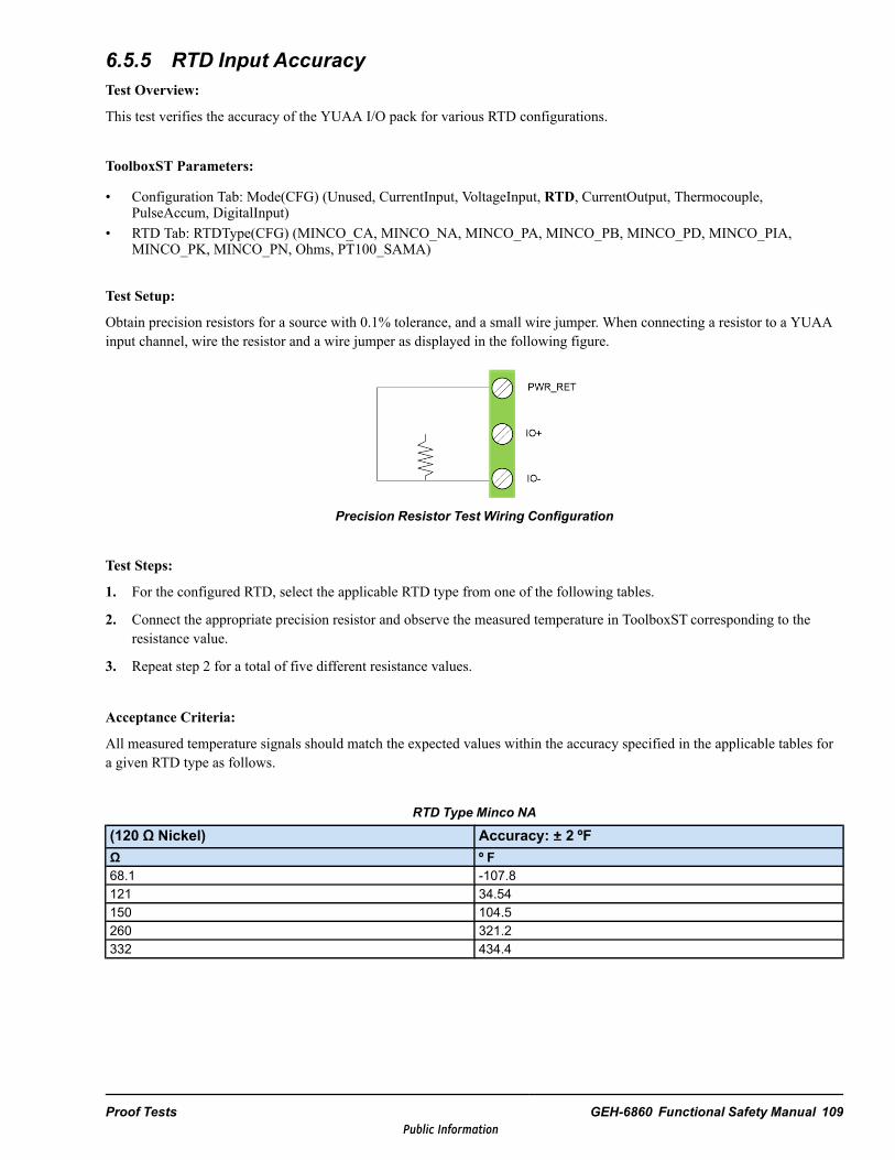
6.5.5 RTD Input AccuracyTest Overview:
This test verifies the accuracy of the YUAA I/O pack for various RTD configurations.
ToolboxST Parameters:
• Configuration Tab: Mode(CFG) (Unused, CurrentInput, VoltageInput, RTD, CurrentOutput, Thermocouple,PulseAccum, DigitalInput)
• RTD Tab: RTDType(CFG) (MINCO_CA, MINCO_NA, MINCO_PA, MINCO_PB, MINCO_PD, MINCO_PIA,MINCO_PK, MINCO_PN, Ohms, PT100_SAMA)
Test Setup:
Obtain precision resistors for a source with 0.1% tolerance, and a small wire jumper. When connecting a resistor to a YUAAinput channel, wire the resistor and a wire jumper as displayed in the following figure.
Precision Resistor Test Wiring Configuration
Test Steps:
1. For the configured RTD, select the applicable RTD type from one of the following tables.
2. Connect the appropriate precision resistor and observe the measured temperature in ToolboxST corresponding to theresistance value.
3. Repeat step 2 for a total of five different resistance values.
Acceptance Criteria:
All measured temperature signals should match the expected values within the accuracy specified in the applicable tables fora given RTD type as follows.
RTD Type Minco NA
(120 ΩΩ Nickel) Accuracy: ±± 2 ºFΩ º F68.1 -107.8121 34.54150 104.5260 321.2332 434.4
Proof Tests GEH-6860 Functional Safety Manual 109Public Information
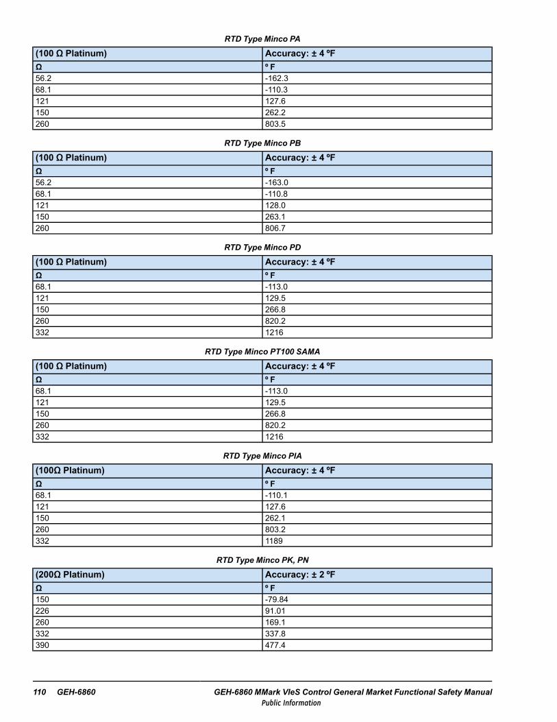
RTD Type Minco PA
(100 ΩΩ Platinum) Accuracy: ±± 4 ºFΩ º F56.2 -162.368.1 -110.3121 127.6150 262.2260 803.5
RTD Type Minco PB
(100 ΩΩ Platinum) Accuracy: ±± 4 ºFΩ º F56.2 -163.068.1 -110.8121 128.0150 263.1260 806.7
RTD Type Minco PD
(100 ΩΩ Platinum) Accuracy: ±± 4 ºFΩ º F68.1 -113.0121 129.5150 266.8260 820.2332 1216
RTD Type Minco PT100 SAMA
(100 ΩΩ Platinum) Accuracy: ±± 4 ºFΩ º F68.1 -113.0121 129.5150 266.8260 820.2332 1216
RTD Type Minco PIA
(100ΩΩ Platinum) Accuracy: ±± 4 ºFΩ º F68.1 -110.1121 127.6150 262.1260 803.2332 1189
RTD Type Minco PK, PN
(200ΩΩ Platinum) Accuracy: ±± 2 ºFΩ º F150 -79.84226 91.01260 169.1332 337.8390 477.4
110 GEH-6860 GEH-6860 MMark VIeS Control General Market Functional Safety ManualPublic Information

RTD Type Minco CA
(10ΩΩ Copper) Accuracy: ±± 10 ºFΩ º F7.5 -39.5510 76.9813 216.815 310.018 448.5
6.5.6 Open RTD Inputs DetectionTest Overview:
This test demonstrates that the YUAA I/O pack can successfully recognize when an RTD input becomes an open circuit.
Test Setup:
For each appropriate channel, select a precision resistor and wire it in accordance with the figure Precision Resistor TestWiring Configuration provided in the section RTD Input Accuracy, sub-section Test Setup. To choose a resistor value, refer tothe RTD Type tables provided in the section RTD Input Accuracy and pick one of the five values pertaining to the configuredRTD type.
Test Steps:
1. From the ToolboxST application, confirm that each of the configured RTD channel’s temperature readings is at anapproximate range for the application.
2. Disconnect the wire connections to the PWR_RET screw terminal of the configured RTD channels to create an opencircuit.
3. From the ToolboxST application, confirm that the I/O pack generates a diagnostic as a result of the open circuit.
4. Return the channel to a normal condition and confirm that the diagnostic goes inactive.
5. Repeat steps 2 through 4 for each appropriate channel.
Acceptance Criteria:
Designated channels properly generate a diagnostic when the circuit is opened.
Proof Tests GEH-6860 Functional Safety Manual 111Public Information
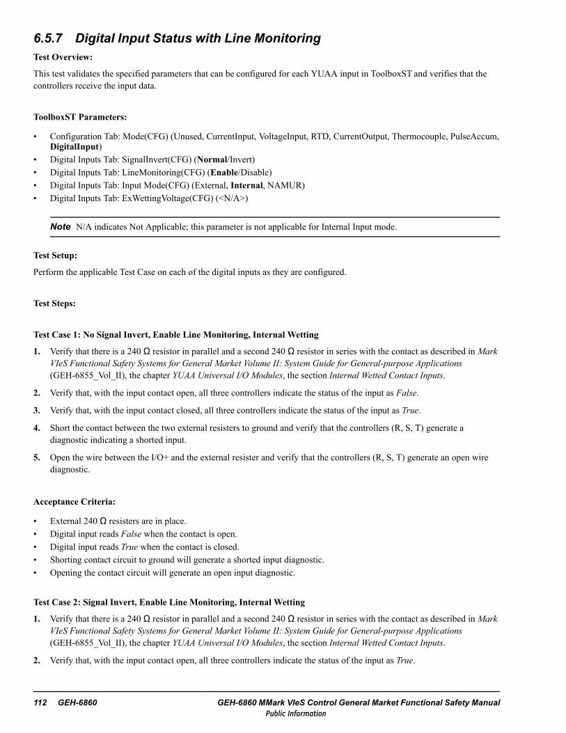
6.5.7 Digital Input Status with Line MonitoringTest Overview:
This test validates the specified parameters that can be configured for each YUAA input in ToolboxST and verifies that thecontrollers receive the input data.
ToolboxST Parameters:
• Configuration Tab: Mode(CFG) (Unused, CurrentInput, VoltageInput, RTD, CurrentOutput, Thermocouple, PulseAccum,DigitalInput)
• Digital Inputs Tab: SignalInvert(CFG) (Normal/Invert)• Digital Inputs Tab: LineMonitoring(CFG) (Enable/Disable)• Digital Inputs Tab: Input Mode(CFG) (External, Internal, NAMUR)• Digital Inputs Tab: ExWettingVoltage(CFG) (<N/A>)
Note N/A indicates Not Applicable; this parameter is not applicable for Internal Input mode.
Test Setup:
Perform the applicable Test Case on each of the digital inputs as they are configured.
Test Steps:
Test Case 1: No Signal Invert, Enable Line Monitoring, Internal Wetting
1. Verify that there is a 240 Ω resistor in parallel and a second 240 Ω resistor in series with the contact as described in MarkVIeS Functional Safety Systems for General Market Volume II: System Guide for General-purpose Applications(GEH-6855_Vol_II), the chapter YUAA Universal I/O Modules, the section Internal Wetted Contact Inputs.
2. Verify that, with the input contact open, all three controllers indicate the status of the input as False.
3. Verify that, with the input contact closed, all three controllers indicate the status of the input as True.
4. Short the contact between the two external resisters to ground and verify that the controllers (R, S, T) generate adiagnostic indicating a shorted input.
5. Open the wire between the I/O+ and the external resister and verify that the controllers (R, S, T) generate an open wirediagnostic.
Acceptance Criteria:
• External 240 Ω resisters are in place.• Digital input reads False when the contact is open.• Digital input reads True when the contact is closed.• Shorting contact circuit to ground will generate a shorted input diagnostic.• Opening the contact circuit will generate an open input diagnostic.
Test Case 2: Signal Invert, Enable Line Monitoring, Internal Wetting
1. Verify that there is a 240 Ω resistor in parallel and a second 240 Ω resistor in series with the contact as described in MarkVIeS Functional Safety Systems for General Market Volume II: System Guide for General-purpose Applications(GEH-6855_Vol_II), the chapter YUAA Universal I/O Modules, the section Internal Wetted Contact Inputs.
2. Verify that, with the input contact open, all three controllers indicate the status of the input as True.
112 GEH-6860 GEH-6860 MMark VIeS Control General Market Functional Safety ManualPublic Information
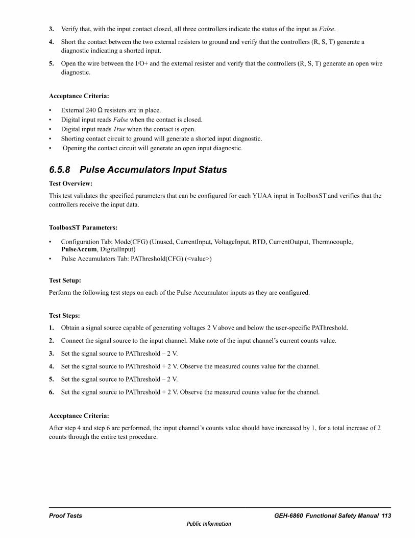
3. Verify that, with the input contact closed, all three controllers indicate the status of the input as False.
4. Short the contact between the two external resisters to ground and verify that the controllers (R, S, T) generate adiagnostic indicating a shorted input.
5. Open the wire between the I/O+ and the external resister and verify that the controllers (R, S, T) generate an open wirediagnostic.
Acceptance Criteria:
• External 240 Ω resisters are in place.• Digital input reads False when the contact is closed.• Digital input reads True when the contact is open.• Shorting contact circuit to ground will generate a shorted input diagnostic.• Opening the contact circuit will generate an open input diagnostic.
6.5.8 Pulse Accumulators Input StatusTest Overview:
This test validates the specified parameters that can be configured for each YUAA input in ToolboxST and verifies that thecontrollers receive the input data.
ToolboxST Parameters:
• Configuration Tab: Mode(CFG) (Unused, CurrentInput, VoltageInput, RTD, CurrentOutput, Thermocouple,PulseAccum, DigitalInput)
• Pulse Accumulators Tab: PAThreshold(CFG) (<value>)
Test Setup:
Perform the following test steps on each of the Pulse Accumulator inputs as they are configured.
Test Steps:
1. Obtain a signal source capable of generating voltages 2 Vabove and below the user-specific PAThreshold.
2. Connect the signal source to the input channel. Make note of the input channel’s current counts value.
3. Set the signal source to PAThreshold – 2 V.
4. Set the signal source to PAThreshold + 2 V. Observe the measured counts value for the channel.
5. Set the signal source to PAThreshold – 2 V.
6. Set the signal source to PAThreshold + 2 V. Observe the measured counts value for the channel.
Acceptance Criteria:
After step 4 and step 6 are performed, the input channel’s counts value should have increased by 1, for a total increase of 2counts through the entire test procedure.
Proof Tests GEH-6860 Functional Safety Manual 113Public Information

6.5.9 Low Source VoltageTest Overview:
This test is used to monitor the common source voltage for the YUAA to detect a power interruption and provide faulttolerance for the I/O functions.
Test Setup:
Prepare the system for a fail-safe response from the I/O pack.
Test Steps:
1. Disconnect the 28 V dc power supply connection from the I/O pack.
2. Confirm that all the inputs go Unhealthy.
Acceptance Criteria:
• With the I/O pack’s power removed, all inputs are displayed as Unhealthy.• Variable PS28V_YUAA is set to False or Unhealthy.
114 GEH-6860 GEH-6860 MMark VIeS Control General Market Functional Safety ManualPublic Information

6.6 YVIB Test ProceduresThis test plan is designed for a generic configuration as described in each Test Steps section. Due to the large number ofpossible configurations for each signal type, some adjustment is necessary in the expected results if the configuration isdifferent from the generic type. Refer toMark VIeS Functional Safety Systems for General Market Volume II: System Guidefor General-purpose Applications (GEH-6855_Vol_II) for functional differences based on configuration parameters. It is notnecessary to alter the configuration to conduct this test plan but results may vary based on configuration.
6.6.1 Vibration (VibProx, VibProx-KPH) Input AccuracyTest Overview:
This test verifies the accuracy of the YVIB vibration configured as VibProx, VibProx-KPH.
Test Setup:
Obtain a function generator capable of sinusoid signals of 10 V dc pp and ±5 V dc offsets.
To preserve field wiring, remove the wired terminal block and replace it with a test block for the following set of tests.Replace the field wired terminal block when testing is complete.
TVBAS2 Vibration Terminal Board
Note Darkened box indicates proper jumper settings.
For each of the configure channels 1-8 configured for vibration inputs, the following generic configuration is assumed:
Attention
The rows highlighted in green in the following tables contain the configuration valuesto use to perform the proof test for the indicated vibration input channels.
The generic configuration in the following table is assumed for each of the configured channels 1-8 configured for vibrationinputs.
Generic Configuration Parameters for All Channels
Vib_PP_Fltr
MaxVolt_Prox
MinVolt_Prox
MaxVolt_KP
MinVolt_KP
MaxVolt_Seis
MinVolt_Seis
MaxVolt_Acc
MinVolt_Acc
MaxVolt_Vel
MinVolt_Vel
SystemLimits
0.04 to 2.0sec
-4.0 to 0.0 Vdc
-24.0 to-16.0 V dc
-4.0 to 0.0 Vdc
-24.0 to-16.0 V dc
0.0 to 1.5 Vdc
-1.5 to 0.0V dc
-12.0 to 1.5V dc
-24.0 to-1.0 V dc
-12.0 to 1.5V dc
-24.0 to-1.0 V dc
EnableDisable
0.1 -1.5 -18.5 -1.5 -22 1 -1 -8.5 -11.5 -8.375 -15.625 Enable
Proof Tests GEH-6860 Functional Safety Manual 115Public Information

Gap (Gap 1-3) Configuration for GAP1_VIB1 through GAP3_VIB3
VIB_ Type4 ScaleScale_Off
TMR_DiffLimt
GnBiasOvride
Snsr_Offset
GainLMlpcutoff
SysLim1Enabl
SysLim1Latch
SysLim1Type
SysLimit1
SysLim2Enabl
SysLim2Latch
SysLim2Type
SysLimit2
PosProxUnused
VibLMAccelVibProx
VibProx-KPHVibSeismicVibVelomitor
volts/milor
volts/ips
±13.3V dc
-1200 to+1200
DisableEnable
0 to xV dc
1x2x4x8x
1.52.02.53.03.54.04.5
5.0 Hz
DisableEnable
LatchNotLatch
<=>=
-1200to
+1200
DisableEnable
LatchNotLatch
<=>=
-1200to
+1200
VibProx-KPH 0.1 0 2 Enable 2.5 1x 5 Disable N/A N/A N/A Disable N/A N/A N/A
Gap (Gap 4-8) Configuration for GAP4_VIB4 through GAP8_VIB8
VIB_Type Scale
Scale_Off
TMR_DiffLimt
GnBiasOvride
Snsr_Offset
GainSysLim1Enabl
SysLim1Latch
SysLim1Type
SysLimit1
SysLim2Enabl
SysLim2Latch
SysLim2Type
SysLimit2
PosProxUnusedVibProx
VibProx-KPHVibSeismicVibVelomitor
volts/milor
volts/ips
±13.3V dc
-1200to
+1200
DisableEnable
±13.3V dc
1x2x4x8x
DisableEnable
LatchNotLatch
<=>=
-1200to
+1200
DisableEnable
LatchNotLatch
<=>=
-1200to
+1200
VibProx-KPH 0.1 0 2 Enable 2.5 1x Disable N/A N/A N/A Disable N/A N/A N/A
If the vibration inputs under test are configured differently from the settings listed in the previous tables, the input signal orresults should be adjusted to conform to the actual configuration. For example, if a high pass filter is employed, then the testsignal frequency should be within the high pass frequency filter band.
In this test a 6 V dc pp with a –5 V dc offset will be read as a 60 mil vibration with a 50 mil gap. As an alternative, use ashaker table connected to vibration sensor to provide a reference input signal.
Test Steps:
1. Configure the signal source to apply a 50 Hz sine wave (6 V dc pp) with a dc offset of –5 V dc.
2. Document the value that the YVIB reads for each value, as seen in I/O Live Value in the Vib 1-8 tab. The first inputchannel will be called VIB1. The nominal value should be 60 mils.
3. Document the value that the YVIB reads for each value, as seen in I/O Live Value in the Gap 1-3 tab. The first inputchannel will be called GAP1_VIB1. The nominal value should be 50.
4. Document the value that the YVIB reads for each value, as seen in I/O Live Value in the Gap 4-8 tab. The first inputchannel will be called GAP4_VIB4. The nominal value should be 50.
5. Increase the signal frequency to 700 Hz.
6. Repeat steps through 5 for all vibration inputs configured as VibProx or VibProx-KPH.
Acceptance Criteria:
• For Vibration signals (VIB1-8) 5-200 Hz 1% at 3 V dc pp (±0.03 V dc) or ±0.3 mils scaled to 0.1 V dc/mil.• For Vibration signals (VIB1-8) 200-700 Hz 5% at 3 V dc pp (±0.15 V dc) or ±1.5 mils scaled to 0.1 V dc/mil.• For Gap signal (GAP1_VIB1-GAP8_VIB8) 1% FS (±0.2 V dc) or ±2.0 mils scaled to 0.1 V dc/mil.
116 GEH-6860 GEH-6860 MMark VIeS Control General Market Functional Safety ManualPublic Information
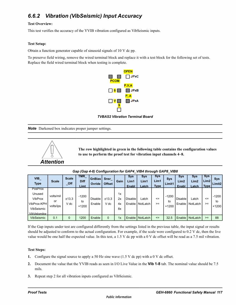
6.6.2 Vibration (VibSeismic) Input AccuracyTest Overview:
This test verifies the accuracy of the YVIB vibration configured as VibSeismic inputs.
Test Setup:
Obtain a function generator capable of sinusoid signals of 10 V dc pp.
To preserve field wiring, remove the wired terminal block and replace it with a test block for the following set of tests.Replace the field wired terminal block when testing is complete.
TVBAS2 Vibration Terminal Board
Note Darkened box indicates proper jumper settings.
Attention
The row highlighted in green in the following table contains the configuration valuesto use to perform the proof test for vibration input channels 4–8.
Gap (Gap 4-8) Configuration for GAP4_VIB4 through GAP8_VIB8
VIB_Type Scale
Scale_Off
TMR_DiffLimt
GnBiasOvride
Snsr_Offset
GainSysLim1Enabl
SysLim1Latch
SysLim1Type
SysLimit1
SysLim2Enabl
SysLim2Latch
SysLim2Type
SysLimit2
PosProxUnusedVibProx
VibProx-KPHVibSeismicVibVelomitor
volts/milor
volts/ips
±13.3V dc
-1200to
+1200
DisableEnable
±13.3V dc
1x2x4x8x
DisableEnable
LatchNotLatch
<=>=
-1200to
+1200
DisableEnable
LatchNotLatch
<=>=
-1200to
+1200
VibSeismic 0.1 0 1200 Enable 0 1x Enable NotLatch <= 32.5 Enable NotLatch >= 88
If the Gap inputs under test are configured differently from the settings listed in the previous table, the input signal or resultsshould be adjusted to conform to the actual configuration. For example, if the scale were configured to 0.2 V dc, then the livevalue would be one half the expected value. In this test, a 1.5 V dc pp with a 0 V dc offset will be read as a 7.5 mil vibration.
Test Steps:
1. Configure the signal source to apply a 50 Hz sine wave (1.5 V dc pp) with a 0 V dc offset.
2. Document the value that the YVIB reads as seen in I/O Live Value in the Vib 1-8 tab. The nominal value should be 7.5mils.
3. Repeat step 2 for all vibration inputs configured as VibSeismic.
Proof Tests GEH-6860 Functional Safety Manual 117Public Information

4. Increase the signal frequency to 330 Hz.
5. Repeat step 2 for all vibration inputs configured as VibSeismic.
Acceptance Criteria:
Vibration seismic readings are accurate within 0.2 mils at 50 Hz and 0.5 mils at 660 Hz.
6.6.3 Position Proximeter (PosProx) AccuracyTest Overview:
This test checks the accuracy of the YVIB configured position proximeter inputs, including:
• The vibration input module provides 4 channels of signal conditioning for field wired position inputs.• The analog input function can be configurable by the controller over IONet communications.
Note The Open Circuit Detection test can be conducted simultaneously with this test for PosProx configured channels.
Test Setup:
• Obtain a signal source capable of providing a dc signal of –1 to –9 V dc.• To preserve field wiring, remove the wired terminal block and replace it with a test block for the following set of tests.
Replace the field wired terminal block when testing is complete.
TVBAS2 Vibration Terminal Board
Note Darkened box indicates proper jumper settings.
Attention
The row highlighted in green in the following table contains the configuration valuesto use to perform the proof test for position input channels 9–12.
Gap (Gap 9-12) Configuration for GAP9_POS1 through GAP12_POS4
VIB_Type Scale
Scale_Off
TMR_DiffLimt
GnBiasOvride
Snsr_Offset
GainSysLim1Enabl
SysLim1Latch
SysLim1Type
SysLimit1
SysLim2Enabl
SysLim2Latch
SysLim2Type
SysLimit2
PosProxUnused
volts/milor
volts/ips
±13.3V dc
-1200to
+1200
DisableEnable
±13.3V dc
1x4x
DisableEnable
LatchNotLatch
<=>=
-1200to
+1200
DisableEnable
LatchNotLatch
<=>=
-1200to
+1200PosProx 0.1 0 1200 Enable 2.5 1x Enable NotLatch <= 32.5 Enable NotLatch >= 88
118 GEH-6860 GEH-6860 MMark VIeS Control General Market Functional Safety ManualPublic Information
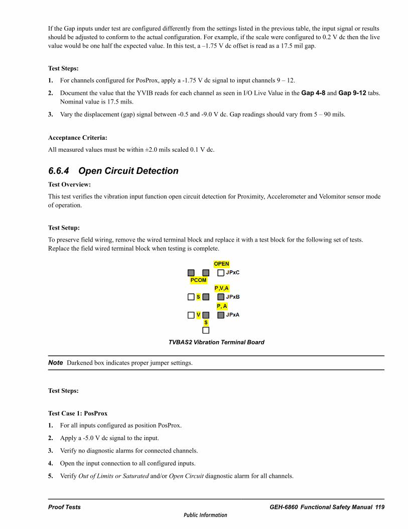
If the Gap inputs under test are configured differently from the settings listed in the previous table, the input signal or resultsshould be adjusted to conform to the actual configuration. For example, if the scale were configured to 0.2 V dc then the livevalue would be one half the expected value. In this test, a –1.75 V dc offset is read as a 17.5 mil gap.
Test Steps:
1. For channels configured for PosProx, apply a -1.75 V dc signal to input channels 9 – 12.
2. Document the value that the YVIB reads for each channel as seen in I/O Live Value in the Gap 4-8 and Gap 9-12 tabs.Nominal value is 17.5 mils.
3. Vary the displacement (gap) signal between -0.5 and -9.0 V dc. Gap readings should vary from 5 – 90 mils.
Acceptance Criteria:
All measured values must be within ±2.0 mils scaled 0.1 V dc.
6.6.4 Open Circuit DetectionTest Overview:
This test verifies the vibration input function open circuit detection for Proximity, Accelerometer and Velomitor sensor modeof operation.
Test Setup:
To preserve field wiring, remove the wired terminal block and replace it with a test block for the following set of tests.Replace the field wired terminal block when testing is complete.
TVBAS2 Vibration Terminal Board
Note Darkened box indicates proper jumper settings.
Test Steps:
Test Case 1: PosProx
1. For all inputs configured as position PosProx.
2. Apply a -5.0 V dc signal to the input.
3. Verify no diagnostic alarms for connected channels.
4. Open the input connection to all configured inputs.
5. Verify Out of Limits or Saturated and/or Open Circuit diagnostic alarm for all channels.
Proof Tests GEH-6860 Functional Safety Manual 119Public Information

Test Case 2: VibLMAccel
1. For all inputs configured as VibLMAccel.
2. Apply a -9.0 V dc signal.
3. Verify no diagnostic alarms for connected channels.
4. Open the input connections to the VibLMAccel configured channels.
5. Verify Out of Limits or Saturated and/or Open Circuit diagnostic alarms for the channels.
Test Case 3: VibVelomitor
1. For all inputs configured as VibVelomitor.
2. Do not apply a test voltage to the inputs.
3. Open the input connection to the VibVelomitor channels.
4. Verify Out of Limits or Saturated and/or Open Circuit diagnostic alarm.
Acceptance Criteria:
The I/O pack is able to detect open circuit conditions and generates a diagnostic.
120 GEH-6860 GEH-6860 MMark VIeS Control General Market Functional Safety ManualPublic Information

6.6.5 Keyphasor Transducer AccuracyTest Overview:
This test verifies the accuracy of the YVIB position Keyphasor transducer input. The vibration input module provides achannel for field wired Keyphasor transducer position input.
Test Setup:
To preserve field wiring, remove the wired terminal block and replace it with a test block for the following set of tests.Replace the field wired terminal block when testing is complete.
TVBAS2 Vibration Terminal Board
Note Darkened box indicates proper jumper settings.
Attention
The row highlighted in green in the following table contains the configuration valuesto use to perform the proof test for vibration input channel 13.
Keyphasor (KPH) Configuration for GAP13_KPH1
Scale_Off
KPH_Thrshld
KPH_Type
TMR_DiffLimt
GnBiasOvride
Snsr_Offset
GainSysLim1Enabl
SysLim1Latch
SysLim1Type
SysLimit1
SysLim2Enabl
SysLim2Latch
SysLim2Type
SysLimit2
±13.3V dc
1 to 5V dc
SlotPedestal
-1200to
+1200
DisableEnable
±13.3V dc
1x2x4x8x
DisableEnable
LatchNotLatch
<=>=
-1200to
+1200
DisableEnable
LatchNotLatch
<=>=
-1200to
+1200
0 2 Slot 1200 Enable 5 1x Enable NotLatch <= 20 Enable NotLatch >= 60
Test Steps:
1. For YVIBS1B, channels 12 and 13 configured for Keyphasor transducer input, apply a 50 Hz pulse waveform with offset-5 V dc, 4 V dc pp, and a high side duty cycle > 55% to appropriate KeyPhasor channel(s).
2. For YVIBS1B, document the revolutions per minute YVIBS1B reads for channels 12 and 13 from the variables, RPM_KPH1 and RPM_KPH2. Nominal value is 3000 rpm.
Note A square wave has a 50% duty cycle and will not function.
Proof Tests GEH-6860 Functional Safety Manual 121Public Information
Acceptance Criteria:
All measured values must be within ±20.0 rpm.
6.6.6 Low Source VoltageTest Overview:
The common source voltage for the analog input loop voltages for two wire transmitters shall be monitored to detect low loopvoltage and provide fault tolerance for this function when more than one I/O processor is present.
Test Setup:
Prepare system for a fail-safe response from the I/O pack.
Test Steps:
1. Disconnect the 28 V dc power supply connection from the I/O pack. For a TMR terminal board disconnect the powersupply from two I/O packs.
2. Confirm that all the inputs go unhealthy.
Acceptance Criteria:
• With the I/O pack’s power removed, all inputs are displayed as Unhealthy.• Variables PS28V_YVIB and PS18V_YVIB are set to False and Unhealthy.
122 GEH-6860 GEH-6860 MMark VIeS Control General Market Functional Safety ManualPublic Information

Appendix: Determine Frame Input ClientCompletion TimeUse the following procedures to determine frame input completion time.
Note Information about the timing of frame input times is available in the Controller Advanced Diagnostics.
To view timing data
1. Unlock the controller by selecting Lock/Unlock from the ToolboxST Device menu and clicking Unlock.
2. From the View menu, select Diagnostics and Controller Advanced Diagnostics to display the ControllerAdvanced Diagnostics dialog box.
3. Collect the timing information by selecting Commands, Diagnostics, Sequencer, Client Data, and then pressSend Command.
Note Without resetting the timing data, the data will likely have overruns and invalid data as minimum and maximum times.
To determine maximum completion time
1. From the Controller Advanced Diagnostics dialog box, reset the timing and overrun counters by selecting Commands,Diagnostics, Sequencer, and Client Data Reset, then press Send Command.
2. Wait for the controller to collect 100,000 samples. For example, if a 10 ms frame period is selected, wait for 100,000 /100 samples per second / 60 seconds per minute = ~ 17 minutes.
3. View timing data. Refer to the procedure To view timing data.
4. Validate timing data. Refer to the procedure To interpret timing data.
Appendix: Determine Frame Input Client Completion Time GEH-6860 Functional Safety Manual 123Public Information
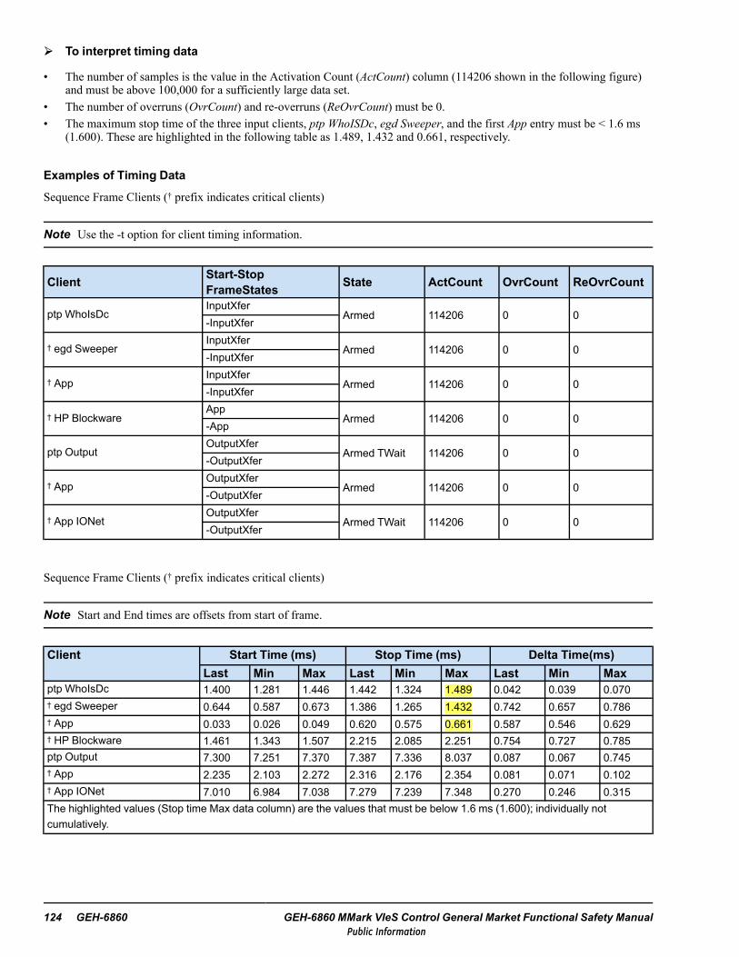
To interpret timing data
• The number of samples is the value in the Activation Count (ActCount) column (114206 shown in the following figure)and must be above 100,000 for a sufficiently large data set.
• The number of overruns (OvrCount) and re-overruns (ReOvrCount) must be 0.• The maximum stop time of the three input clients, ptp WhoISDc, egd Sweeper, and the first App entry must be < 1.6 ms
(1.600). These are highlighted in the following table as 1.489, 1.432 and 0.661, respectively.
Examples of Timing Data
Sequence Frame Clients († prefix indicates critical clients)
Note Use the -t option for client timing information.
Client Start-StopFrameStates State ActCount OvrCount ReOvrCount
ptp WhoIsDcInputXfer
Armed 114206 0 0-InputXfer
† egd SweeperInputXfer
Armed 114206 0 0-InputXfer
† AppInputXfer
Armed 114206 0 0-InputXfer
† HP BlockwareApp
Armed 114206 0 0-App
ptp OutputOutputXfer
Armed TWait 114206 0 0-OutputXfer
† AppOutputXfer
Armed 114206 0 0-OutputXfer
† App IONetOutputXfer
Armed TWait 114206 0 0-OutputXfer
Sequence Frame Clients († prefix indicates critical clients)
Note Start and End times are offsets from start of frame.
Client Start Time (ms) Stop Time (ms) Delta Time(ms)Last Min Max Last Min Max Last Min Max
ptp WhoIsDc 1.400 1.281 1.446 1.442 1.324 1.489 0.042 0.039 0.070† egd Sweeper 0.644 0.587 0.673 1.386 1.265 1.432 0.742 0.657 0.786† App 0.033 0.026 0.049 0.620 0.575 0.661 0.587 0.546 0.629† HP Blockware 1.461 1.343 1.507 2.215 2.085 2.251 0.754 0.727 0.785ptp Output 7.300 7.251 7.370 7.387 7.336 8.037 0.087 0.067 0.745† App 2.235 2.103 2.272 2.316 2.176 2.354 0.081 0.071 0.102† App IONet 7.010 6.984 7.038 7.279 7.239 7.348 0.270 0.246 0.315The highlighted values (Stop time Max data column) are the values that must be below 1.6 ms (1.600); individually notcumulatively.
124 GEH-6860 GEH-6860 MMark VIeS Control General Market Functional Safety ManualPublic Information

Examples of Application Timing
The following table lists applications, configurations, and associated maximum input frame client completion time to use todetermine if a given application will be compatible with the Mark VIeS Functional Safety System. This is for informationalpurposes only and is not meant to replace the user from collecting timing data from their actual physical system.
Controller # Generic TMR Yxxx # VotedBooleans
Largest MaxStop Time (ms)
UCSCS2 23 TMR (3 YVIB, 6 YAIC, 7 YDOA, 7 YDIA) 31968 (max) 1.11
Appendix: Determine Frame Input Client Completion Time GEH-6860 Functional Safety Manual 125Public Information

Notes
126 GEH-6860 GEH-6860 MMark VIeS Control General Market Functional Safety ManualPublic Information

Glossary of TermsThe following terms are from IEC 61508 and IEC 61511. Some terms differ from the definitions in IEC 61508-4 and IEC61511 to reflect differences in the process sector terminology.
Application software Is specific to the user application. It contains logic sequences, permissives, limits, and expressionsthat control the appropriate input, output, calculations, and decisions necessary to meet the SIF requirements.
Architecture The arrangement of hardware and/or software elements in a system. For example, the arrangement ofsubsystems; internal structure of a subsystem; arrangement of software programs.
Basic Process Control System (BPCS) A system that responds to input signals from the process, its associatedequipment, other programmable systems, and/or an operator and generates output signals causing the process and itsassociated equipment to operate in the desired manner. The system does not perform any SIF with aclaimed ≥ SIL 1.
Channel An element or group of elements that independently perform(s) a function. The elements within a channel couldinclude I/O modules, logic systems sensors, and final elements. The term can describe a complete system or a portion of asystem (for example, sensors, or final elements). A dual channel configuration is one with two channels that independentlyperform the same function.
Diagnostic Coverage (DC) Ratio of the detected failure rate to the total failure rate of component or subsystem detectedby diagnostic tests. DC does not include any faults detected by proof tests.
• DC is used to compute the detected (λ detected) and undetected failure rates (λ undetected) from the total failure rate (λ totalfailure rate) as follows: λ detected = DC× λ total failure rate and λ undected = (1-DC) × λ total failure rate.
• DC is applied to components or subsystems of a SIS. For example, dc is typically determined for a sensor, final element,or logic solver.
• For safety applications, dc is typically applied to the safe and dangerous failures of a component or subsystem. Forexample, the dc for the dangerous failures of a component or subsystem is DC= λDD/λDT, where λDD is the dangerousdetected failure rate and λDT is the total dangerous failure rate.
Electrical/Electronic/Programmable (E/E/PE) Based on electrical (E) and/or electronic (E) and/or programmableelectronic (PE) technology. E/E/PE is intended to cover any and all devices or systems operating on electrical principles,including electro-mechanical devices (electrical), solid-state non-programmable electronic devices (electronic), and electronicdevices based on computer technology (programmable electronic).
External risk reduction facilities Measures to reduce or mitigate risks that are separate and distinct from the MarkVIeS Functional Safety System. Examples include a drain system, firewall, bund (dike).
Fault tolerance The ability of a functional unit to continue to perform a required function in the presence of faults orerrors.
Final element Part of a system that implements the physical action necessary to achieve a safe state.
Frame rate The basic scheduling period of the controller encompassing one complete input compute-output cycle for thecontroller. It is the system-dependent scan rate.
Functional safety Part of the overall safety relating to the process and the BPCS that depends on the correct functioningof the system and other protection layers.
GEH-6860 Glossary of Terms 127Public Information

Logic solver That portion of either a BPCS or safety control that performs one or more logic function(s). Examplesinclude electrical systems, electronic systems, programmable electronic systems, pneumatic systems, and hydraulic systems.Sensors and final elements are not part of the logic solver. In IEC 61511 the following terms for logic systems are used:
• electrical logic systems for electro-mechanical technology• electronic logic systems for electronic technology• PE logic system for programmable electronic systems
Mode of operation The way in which a SIF operates.
Demand mode is where a specified action (such as the closing of a valve) is taken in response to process conditions or otherdemands. In the event of a dangerous failure of the SIF, a potential hazard only occurs in the event of a failure in the processor the BPCS.
Continuous mode is where in the event of a dangerous failure of the safety-instrumented function a potential hazard willoccur without further failure unless action is taken to prevent it. Continuous mode covers those SIFs that implementcontinuous control to maintain functional safety.
In demand mode applications where the demand rate is more frequent than once per year, the hazard rate will not be higherthan the dangerous failure rate of the SIF. In such a case, it will normally be appropriate to use the continuous mode criteria.
128 GEH-6860 MMark VIeS Control General Market Functional Safety ManualPublic Information

Process risk A risk arising from the process conditions caused by abnormal events, including BPCS malfunction. Therisk in this context is that associated with the specific hazardous event in which the safety control is be used to provide thenecessary risk reduction (that is, the risk associated with functional safety).
Process risk analysis is described in IEC 61511-3. The main purpose of determining the process risk is to establish a referencepoint for the risk without taking into account the protection layers. Assessment of this risk should include associated humanfactor issues.
Note This term equates to EUC risk in IEC 61508-4.
Proof test A test performed to reveal undetected faults in a safety control so that, if necessary, the system can be restoredto its designed functionality.
Protection layer Any independent mechanism that reduces risk by control, prevention, or mitigation.
Risk Combination of the frequency of occurrence of harm and the severity of that harm.
Safe state Process state when safety is achieved. In going from a potentially hazardous condition to the final safe state,the process may cross several intermediate safe-states. For some situations, a safe state exists only as long as the process iscontinuously controlled. Such control may be for a short or indefinite period of time.
Safety function A function to be implemented by a safety controller, other technology safety-related system, or externalrisk reduction facilities, which is intended to achieve or maintain a safe state for the process, with respect to a specifichazardous event.
Safety-instrumented Function (SIF) A safety function with a specified SIL that is necessary to achieve functionalsafety. This function can be either a safety-instrumented protection function or a safety-instrumented control function.
Safety-instrumented System (SIS) An instrumented system used to implement one or more SIFs. A SIS is composedof any combination of sensors, logic solvers, and final elements. This can include either safety-instrumented control functionsor safety-instrumented protection functions or both. A SIS may or may not include software.
When human action is part of a SIS, the availability and reliability of operator action must be specified in the SafetyRequirements Specification (SIS) and included in SIS performance calculations. Refer to IEC 61511-2 on how to includeoperator availability and reliability in SIL calculations.
Safety integrity The average probability of a system satisfactorily performing the required SIF under all the statedconditions within a stated period of time. The higher the SIL, the higher the probability that the required SIF will be carriedout. There are four levels of safety integrity for SIFs.
In determining safety integrity, all causes of failures (random hardware and systematic failures) that lead to an unsafe stateshould be included, such as hardware failures, software induced failures, and failures due to electrical interference. Somefailures, particularly random hardware failures, may be quantified using such measures as the failure rate in the dangerousmode of failure or the probability of a SIF failing to operate on demand. However, the safety integrity of an SIF also dependson many factors, which cannot be accurately quantified but can only be considered qualitatively. Safety integrity includeshardware and systematic integrity.
Safety Integrity Level (SIL) A discrete level (one out of four) for specifying the safety integrity requirements of the SIFsto be allocated to the safety control. SIL 4 has the highest level of safety integrity while SIL 1 has the lowest. It is possible touse several lower SIL systems to satisfy the need for a higher level function (for example, using a SIL 2 and a SIL 1 systemtogether to satisfy the need for a SIL 3 function).
GEH-6860 Glossary of Terms 129Public Information

Target failure measure The intended probability of dangerous mode failures to be achieved in respect to the safetyintegrity requirements, specified in terms of either the average probability of failure to perform the design function on demand(for demand mode) or the frequency of a dangerous failure to perform the SIF per hour (for continuous mode).
Validation Activity of demonstrating that the SIF(s) and safety control(s) under consideration after installation meet theSRS in all respects.
130 GEH-6860 MMark VIeS Control General Market Functional Safety ManualPublic Information


Public Information