GEFAHR1 - Boeters Ketel Constructie BV 32 - 62 - 82 - ENGELS.pdf · Landis & Staefa Division 4564...
14
CM1N4564E 01.2001 Siemens Building Technologies Landis & Staefa Division 4 564 Electro-hydraulic actuators for valves with 20 or 40 mm stroke SKB32... SKC32... SKB82... SKC82... SKB62... SKC62... • SK...32...: AC 230 V operating voltage, 3-position signal • SK...82...: AC 24 V operating voltage, 3-position signal • SK...62 : AC 24 V operating voltage, DC 0...10 V positioning signal • SK...62U: AC 24 V operating voltage, DC 0...10 V or 4...20 mA positioning signal • The units come with or without spring return as per DIN 32 730 • Function enhancement by means of auxiliary switch, potentiometer, stroke limiter, stem heating element, and stroke inverter • Positioning force 2800 N • For direct valve mounting without additional setting tasks • With manual adjustment and position indication • SK...U are UL approved Use To actuate two-port and three-port valves of type series VVF... and VXF... with 20 or 40 mm stroke. • Field of use as per IEC 721-3-3 Class 3K5 • Ambient temperatures: − 1 5 ... + 55°C • Medium temperature inside the valve: − 25 ... + 220°C > 220 ... 350°C: use special extension on valve < 0°C: ASZ6.5 stem heating element required
Transcript of GEFAHR1 - Boeters Ketel Constructie BV 32 - 62 - 82 - ENGELS.pdf · Landis & Staefa Division 4564...

CM1N4564E01.2001
Siemens Building TechnologiesLandis & Staefa Division
4564
Electro-hydraulicactuators for valveswith 20 or 40 mm stroke
SKB32... SKC32...SKB82... SKC82...SKB62... SKC62...
• SK...32...: AC 230 V operating voltage, 3-position signal• SK...82...: AC 24 V operating voltage, 3-position signal• SK...62 : AC 24 V operating voltage, DC 0...10 V positioning signal• SK...62U: AC 24 V operating voltage, DC 0...10 V or 4...20 mA positioning signal• The units come with or without spring return as per DIN 32 730• Function enhancement by means of auxiliary switch, potentiometer, stroke
limiter, stem heating element, and stroke inverter• Positioning force 2800 N• For direct valve mounting without additional setting tasks• With manual adjustment and position indication• SK...U are UL approved
Use
To actuate two-port and three-port valves of type series VVF... and VXF...with 20 or 40 mm stroke.• Field of use as per IEC 721-3-3 Class 3K5• Ambient temperatures: −15 ... +55°C• Medium temperature inside the valve: −25 ... +220°C
> 220 ... 350°C: use special extension on valve< 0°C: ASZ6.5 stem heating element required

2/14
Siemens Building Technologies Electro-hydraulic actuators for valves CM1N4564ELandis & Staefa Division 01.2001
Functions
• Voltage on Y1: The pump delivers hydraulic oil from the suction chamber to thepressure chamber and thereby generates the stroke: the valve stem retracts, thethrough-port opens.
• Voltage on Y2: The bypass valve opens and thereby enables the hydraulic oil toreturn from the pressure chamber to the suction chamber by means of the tensionedreturn spring in the actuator: the valve stem extends, the through-port closes.
• No voltage on Y1 or Y2: Both actuator and valve remain in the respective strokeposition.
• The SKB32.51, SKB82.51, SKC32.61und SKD82.61 actuators with spring returnfeature a second bypass valve that opens on voltage failure. The actuator returns to0% stroke via the return spring and closes the valve as per the DIN 32 730 safetyrequirements.
The «open» or «close» functions largely match those of actuators with 3-positionsignals, but feature an intermediary electronic circuit with AC 24 V operating voltageand a DC 0...10 V or DC 4...20 mA positioning signal.The SK...62... and SK...62...U actuators have a factory-installed spring return, i.e., oninterruption of the positioning signals or the operating voltage, the actuator returns to«0%» stroke.The SK...62U actuators can either be driven via a DC 0...10 V or a DC 4...20 mApositioning signal and, additionally, they are UL approved.
Via a selector plug on the circuit board, the flow characteristics for the VVF... andVXF... valves can be changed from «equal percentage» to «linear». On delivery, theactuator with the above listed L&S valves generates an equal-percentage flowcharacteristic.
Relationship between the DC 0…10 V or DC 4…20 mA positioning signal andvolumetric flow:
0 10 V
lin
log
V100
4 20 mA
V
H
Y, R U
H
Y, R
V
V
lin
H
Y
log
U
H
V0
0 1000 Ω
4564
D0
2EFeedback signal
Actuator
Valve
Y = DC 0...10 V
R = 0...1000 Ω or DC 4...20 mA(only for SK...62U)
U = DC 0 ... 10 V or DC 4 ... 20 mA
H = Stroke (Valve)
V = Air volumeV100 = Volumetric flow 100 %V0 = Volumetric flow 0 %
log = Equal-percentage valve characteristic(factory setting)
lin = Linear valve characteristic
SK...32..., SK...82...3-position signal
SK...62..., SK...62...Positioning signalDC 0...10 V or DC 4...20 mA
Selection offlow characteristic
Flow characteristics

3/14
Siemens Building Technologies Electro-hydraulic actuators for valves CM1N4564ELandis & Staefa Division 01.2001
Type summary
Type Stroke Operating Control type Spring return Runtimevoltage (Positioning signal) function time open close
SKB32.50 20 mm AC 230 V 3-position no -- 120 s 120 s
SKB32.51 yes 10 s
SKB82.50 AC 24 V no --
SKB82.51 yes 10 s
SKB62 DC 0 ... 10 V yes 15 s 15 s
SKC32.60 40 mm AC 230 V 3-position no -- 120 s
SKC32.61 yes 18 s
SKC82.60 AC 24 V no --
SKC82.61 yes 18 s
SKC62 DC 0 ... 10 V yes 20 s 20 s
Type Stroke Operating Control type Spring return Runtimevoltage (Positioning signal) function time open close
SKB82.50U 20 mm AC 24 V 3-position no -- 120 s 120 s
SKB82.51U yes 10 s
SKB62U DC 0 ... 10 V
or
DC 4 ... 20 mA
yes 15 s 15 s
SKC82.60U 40 mm 3-position no -- 120 s
SKC82.61U yes 18 s
SKC62U DC 0 ... 10 V
or
DC 4 ... 20 mA
yes 20 s 20 s
Name Type Foractuators
Mounting location
Double auxiliary switch ASC9.3 SK...32... 1 x ASC9.3
Potentiometer 1000 Ω ASZ7.3 SK...82... 1 x ASZ7.3
Potentiometer 135 Ω ASZ7.31 1 x ASZ7.31
Potentiometer 200 Ω ASZ7.32 1 x ASZ7.32
Auxiliary switch ASC1.6 SK...62... 1 x ASC1.6
Stroke limiter 1) ASZ62.6 1 x ASZ62.6
AC 24 V stem heating ASZ6.5 SK...32... 1 x ASZ6.5
SK...82... or
Stroke inverter ASK50 SK...62... 1 x ASK50 2)
1) can only be driven by a DC 0...10 V signal2) Only one accessory may be mounted between the valve and the actuator
Ordering
On ordering, indicate the actuator type and, where required, the accessory type:
Example: 1 SKC32.60 actuator and1 ASZ7.31 potentiometer 135 ΩΩΩΩ
Actuator, valve and accessories are packed and delivered separately and are notmounted on delivery.
Standard versions
Special,UL-approved versions:
Accessories
Delivery

4/14
Siemens Building Technologies Electro-hydraulic actuators for valves CM1N4564ELandis & Staefa Division 01.2001
Equipment combinations
The SKB... and SKC... actuators allow for actuating two-port and three-port valves oftype series VVF... and VXF... with 20 or 40 mm stroke:
Type DN PN Data sheet
Two-port valves VV... (control or safety shutoff valves)
VVF21... (Flange) 25 ... 100 mm 6 bar 4310
VVF31... (Flange) 25 ... 150 mm 10 bar 4320
VVF40... (Flange) 15 ... 150 mm 16 bar 4330
VVF41... (Flange) 50 ... 150 mm 16 bar 4340
VVF45... (Flange) 50 ... 150 mm 16 bar 4345
VVF52... (Flange) 15 ... 40 mm 25 bar 4373
VVF61... (Flange) 15 ... 150 mm 40 bar 4382
Zhree-port valves VX... (control valves for «mixing» and «diverting» functions)
VXF21... (Flange) 25 ... 100 mm 6 bar 4410
VXF31... (Flange) 25 ... 150 mm 10 bar 4420
VXF40... (Flange) 15 ... 150 mm 16 bar 4430
VXF41... (Flange) 15 ... 150 mm 16 bar 4440
VXF61... (Flange) 15 and 25 mm 40 bar 4482
See the associated valve data sheets for permissible differential and close-off pressures ∆pmax and ∆ps
Mechnical design
• Maintenance-free, electro-hydraulic actuators• Pump, pressure cylinder and piston to open the valve• Return spring and bypass valve to close the valve• The SK...32... and SK...82... actuators alternately come with or without spring return
as per DIN 32 730• SK...62... actuators have a spring return as a serial standard• Mounting spaces for double auxiliary switches and potentiometer
with SK...32... and SK...82...• Mounting spaces for auxiliary switch and stroke limiter with SK...62...• Integration of stem heating planned for all actuators• Manual stroke adjustment; integrated as a series standard with manual adjustment
knob and position indication• The SKD...U actuators are UL-approved
SK...32..., SK...82..., SK...62...
4564
Z01
3
7
145
286
1 Pressure cylinder2 Piston3 Pump4 Return spring5 Bypass valve6 Coupling7 Manual adjustment8 Position indication (0 to 1)
Principle of the electro-hydraulic actuators

5/14
Siemens Building Technologies Electro-hydraulic actuators for valves CM1N4564ELandis & Staefa Division 01.2001
SK...32..., SK...82..., SK...62...
4564
Z02
1
3
20
1
4
1 Manual adjustment2 Coupling to valve stem3 Position indication (0 to 1)4 Console
SK...32..., SK...82... SK...62...
Y2 21N Y1
4561
Z03
6
5
87
GO G Y R M U
G O G Y R M U
24 V
ACB
4561
Z04
5
6
7
8
5 Terminal strip6 Earthing screw (SKD32...)7 Mounting space for ASC9.3 auxiliary switch8 Mounting space for ASZ7.3 potentiometer
5 Terminal strip6 Selector plug for flow characteristic
«lin» /«log»7 Mounting space for ASZ62.6 stroke limiter8 Mounting space for ASC1.6 auxiliary switch
ASC9.3 double auxiliary switchAdjustable switching points
ASZ7.3... potentiometer0...1000 Ω, 0...135 Ω, 0...200 Ω
4561
Z05
00515
ASC1.6 auxiliary switch ASZ62.6 stroke limiter
5 4 3
4561
Z08
3050
7090
0%
MaxMin
G Y M+
ASZ62.6
4561
Z06
AB
A Plug to select minimum or maximum limitationB Potentiometer to set desired limitation variable
Operating andconnecting elements
Accessories

6/14
Siemens Building Technologies Electro-hydraulic actuators for valves CM1N4564ELandis & Staefa Division 01.2001
ASZ6.5 stem heating− for media below 0°C
− mounting between valve and actuator 1)
ASK50 stroke inverter− 0% stroke on the actuator corresponds to 100%
stroke on the valve
− mounting between valve and actuator 1)
4561
Z09
4561
Z10
1) Only one accessory may be mounted between the valve and the actuator.
See section «Technical data» for more information.
The various material types used require that you disassemble the unit and sortthe components prior to disposal.
Engineering notes
Conduct the electric connections in accordance with local regulations on electricinstallations as well as the internal or connection diagrams on pages 11 and 12.
Observe all safety-related requirements and restrictions to prevent injuries anddamages to goods.
The ASZ6.5 stem heating has a heating output of 30 VA and must keep the valvestem from freezing when used in a cooling range of 0°C ... −−−−25°C. For this case, donot insulate the actuator console and the valve stem, as air circulation must beensured. Do not touch the hot parts without prior protective measures to avoidburns.Non-observance of the above may result in accidents and fires !
Additionally, pay attention to permissible temperatures as listed in sections «Use» and«Technical data». If an auxiliary switch is required, indicate its switching point on theplant schematic.
Mounting notes45
64Z
11
permissible permissible permissible permissible not permissible
The valve mounting instructions are supplied with the actuator. Accessory instructionsare located in the respective accessory's packaging.
Disposal
Mounting positions

7/14
Siemens Building Technologies Electro-hydraulic actuators for valves CM1N4564ELandis & Staefa Division 01.2001
Commissioning notes
During commissioning, check the wiring and conduct a functional check. Additionally,check or make the required settings at the auxiliary switch, the potentiometer, and thestroke limiter.
456
4Z12
0
1
456
4Z1
3
0
1
Coupling fully retracted Coupling fully extended
If the manual adjustment is turned counter-clockwise to the end position, theLandis & Staefa valves of type series VVF... and VXF... are closed (stroke = 0 %).
For automatic operation, the crank (2) on the manual adjustment knob (1) must beengaged. If not engaged, turn the crank counter-clockwise until the display window (3)neither shows the scale (4) nor the crank engagement bar.
1
2
4564
Z14
4564
Z16
Engaged crank (2) on themanual adjustment knob (1)
Display window with invisible scaledial and crank engagement bar
For manual operation, swing out the crank (2) so that the display window (3) becomesvisible. By rotating the crank or the manual adjustment knob (1), the display windowshows the engagement bar and/or the scale dial with stroke indication.
3
4564
Z15
4564
Z17
4
Swung-out crank (2),display window (3)
Display window with scale dial (4)and stroke indication
Automatic operation
Manual operation
8/14
Siemens Building Technologies Electro-hydraulic actuators for valves CM1N4564ELandis & Staefa Division 01.2001
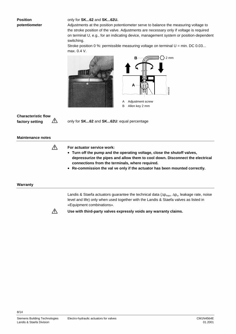
only for SK...62 and SK...62U.Adjustments at the position potentiometer serve to balance the measuring voltage tothe stroke position of the valve. Adjustments are necessary only if voltage is requiredon terminal U, e.g., for an indicating device, management system or position-dependentswitching.Stroke position 0 %: permissible measuring voltage on terminal U = min. DC 0.03...max. 0.4 V.
2 mm
4564
Z20
A
B
A Adjustment screwB Allen key 2 mm
only for SK...62 and SK...62U: equal percentage
Maintenance notes
For actuator service work:• Turn off the pump and the operating voltage, close the shutoff valves,
depressurize the pipes and allow them to cool down. Disconnect the electricalconnections from the terminals, where required.
• Re-commission the val ve only if the actuator has been mounted correctly.
Warranty
Landis & Staefa actuators guarantee the technical data (∆pmax, ∆ps, leakage rate, noiselevel and life) only when used together with the Landis & Staefa valves as listed in«Equipment combinations».
Use with third-party valves expressly voids any warranty claims.
Positionpotentiometer
Characteristic flowfactory setting

9/14
Siemens Building Technologies Electro-hydraulic actuators for valves CM1N4564ELandis & Staefa Division 01.2001
Technische Daten
Power supply Operating voltageSK...32...SK...82...SK...62...
AC 230 V ± 15%AC 24 V ± 20%AC 24 V ± 20%
Frequency 50 or 60 HzControl type
SK...32..., SK...82(U)SK...62...SK...62U
3-positionDC 0 ... 10 V (proportional)DC 0 ... 10 V orDC 4 ... 20 mA (proportional)
Power consumptionSKB32.50SKB82.50(U)SKB32.51SKB82.51(U)SKC32.60, SKC82.60(U)SKC32.61, SKC82.61(U)SKB62(U)SKC62(U)
10 VA13 VA15 VA18 VA19 VA24 VA18 VA28 VA
Function data Positioning force 2800 NNominal stroke
SKB...SKC...
20 mm40 mm
Runtime at 50 HzSK...32..., SK...82...(U)SKB62(U)SKC62(U)
open120 s120 s120 s
close120 s
15 s20 s
Spring return time (close)SKB32.51, SKB82.51(U), SKB62(U)SKC32.61, SKC82.61(U), SKC62(U)
15 s20 s
Signal inputsSK...62(U)
Terminal Y 1)
VoltageCurrent
DC 0 ... 10 Vmax. 0.1 mA
Terminal R 1)
SK...62: Resistance 2)
SK...62U: Resistance 2)
Currentmax. impedance
0 ... 1000 Ω0 ... 1000 ΩDC 4 ... 20 mA250 Ω
Signal outputsSK...62(U)
Terminal U 3)
SK...62: VoltageSK...62U: Voltage
Current
DC 0 ... 10 VDC 0 ... 10 VDC 4 ... 20 mA
Housing protection Housing protection IP54 as per EN 60 529Cable entry glands
SK...32..., SK...82..., SK...62SK...U
Pg 11 (4 x)Pg 16 (4 x)
1) If a DC 4…20 mA control signal is switched to terminal R on SK...62U, terminal Y cannot be usedsimultaneously!
2) If a 0...1000 Ω signal is supplied to input R, the serially integrated wire jumper labelled R – M on thecircuit board must be separated.
3) U at the SK...62U corresponds to either the input signal Y (DC 4...10 V) or the input signal R(if terminal R has a DC 4...20 mA signal).

10/14
Siemens Building Technologies Electro-hydraulic actuators for valves CM1N4564ELandis & Staefa Division 01.2001
Environmental conditions Maximum permissible medium temperatureinside valve ≤ 220°C
OperationClimatic conditionsTemperatureHumidity
as per IEC 721-3-3Class 3K5– 15 ... + 55°C5 ... 95% r.h.
TransportClimatic conditionsTemperatureHumidity
as per IEC 721-3-2Class 2K3– 30 ... + 65°C< 95% r.h.
StorageClimatic conditionsTemperatureHumidity
as per IEC 721-3-1Class 1K3– 15 ... + 55°C0 ... 95% r.h.
Standards CE conformity as per theEMC directiveLow voltage directive
UL approval
89/336/EEC73/23/EECUL 873
Dimensions see «Dimensions»Weights SKB...
SKB82...U, SKB62U
Stroke inverter ASK50
8,40 kg (ohne Verpackung)8,70 kg (mit Verpackung)9,70 kg (ohne Verpackung)
10,00 kg (mit Verpackung)0,95 kg (ohne Verpackung)
1,10 kg (mit Verpackung)Materials Actuator housing and console
Housing box and manual adjustment knobDie-cast aluminiumPlastic
Accessories
Double auxiliary switchASC9.3 Switching output of one auxiliary switch AC 250 V, 6 A ohm., 2.5 A ind.Potentiometer ASZ7.3... Change of overall resistance
of the potentiometer at nominal stroke0 ... 1000 Ω (ASZ7.3)0 ... 135 Ω (ASZ7.31)0 ... 200 Ω (ASZ7.32)
Auxiliary switch ASC1.6 Switching output of auxiliary switch AC 24 V, 10 mA ... 4 A ohm., 2 A ind.Stroke limiter ASZ2.6 1) Possible settings
– maximum stroke limitation for valves,that should not provide the full stroke
– minimum stroke limitation for valves,that must not fully close in a controlledthroughput
6 ... 20 mm (30 ... 100%) 2)
0 ... 14 mm (0 ... 70%) 2)
Stem heating ASZ6.5 Operating voltagePower consumption (heating output)
AC 24 V ± 20%30 VA
1) Can only be driven by a DC 0...10 V signal2) The reference point for limitation is the 0% stroke position of the actuator
(coupling of the actuator fully retracted)

11/14
Siemens Building Technologies Electro-hydraulic actuators for valves CM1N4564ELandis & Staefa Division 01.2001
Internal diagrams
SKB32.50, SKC32.60without spring returnAC 230 V, 3-position
SKB32.51, SKC32.61with spring returnAC 230 V, 3-position
4561
G01
Y1 Y2 3 3 a b c
100 %0 %
100 %
0 %
N 4 5 4 5
1000 Ω
Cm1
c1 c2
ASC9.3 ASZ7.3
4561
G03
Y1 Y2 3 3 a b c
100 %0 %
100 %
0 %
N 4 5 4 5
1000 Ω
Cm1
c1 c2
ASC9.3 ASZ7.3
21
n
SKB82.50(U), SKC82.60(U)without spring returnAC 24 V, 3-position
SKB82.51(U), SKC82.61(U)with spring returnAC 24 V, 3-position
4561
G02
Y1 Y2 3 3 a b c
100 %0 %
100 %
0 %
G 4 5 4 5
1000 Ω
Cm1
c1 c2
ASC9.3 ASZ7.3
4561
G04
Y1 Y2 3 3 a b c
100 %0 %
100 %0 %
G 4 5 4 5
1000 Ω
Cm1
c1 c2
ASC9.3 ASZ7.3
21
n
Y1 Open control valveY2 Close control valve21 Spring return (no voltage
= 0% stroke = valve closed)Cm1 Limit switch for 100% strokec1, c2 Double auxiliary switch ASC9.3Ω Potentiometer ASZ7.3...
Possible mounting spaces for SK...32... and SK...82...:1 Double auxiliary switch ASC9.31 Potentiometer ASZ7.3...1 Stem heating ASZ6.5ASC9.3, ASZ7.3... and ASZ6.5can be mounted together.
G Y(Y') R M U
G0
4561
G05*)
R-M
G, G0 AC 24 V operating voltage:G System potential (SP)G0 System neutral (SN)
Y Control signal input for DC 0...10 V signalY’ Control signal input for DC 0...10 V signal
(only for integrated stroke limiter ASZ62.6)
R Signal input for positioner or frost monitor with 0...1000 Ω signal(for SK...62 and SK...62U) or DC 4...20 mA signal (for SK...62U).When DC 4 ... 20 mA is to be connected, + belongs to R and – to M.
M Measuring neutral
U DC 0...10 V measuring signal output (at Y = DC 0...10 V and/or R = 0...1000 Ω) orDC 4...20 mA measuring signal output (at R = DC 4...20 mA)
*) Wire jumper with label R − M on circuit board. This jumper must be separated when a0...1000 Ω input signal is supplied to terminal R.
3
4 5c1
4561
G06
Switching states related to 100 % stroke of the actuator:– Contact on opening (coupling extension):
Switchover of terminals 3 and 5 to terminals 3 and 4– Contact on closing (coupling retraction):
Switchover of terminals 3 and 4 to terminals 3 and 5
UMRYGGO
3050
7090
0%
MaxMin
G Y M+
ASZ62.6
4561
Z16
Y' Electric plug connection with terminal lugs that areconnected directly to the terminal strip of an SKD62....When a stroke limiter is mounted, the control signalDC 0...10 V on terminal Y’ must be activated on thestroke limiter.
ActuatorsSK...32..., SK...82...
ActuatorsSK...62...
Auxiliary switch ASC1.6
Stroke limiter ASZ62.6

12/14
Siemens Building Technologies Electro-hydraulic actuators for valves CM1N4564ELandis & Staefa Division 01.2001
The connection diagrams show examples for connection possibilities with actuatorsSK...62.... The number and type of connections depend on the plant.
SK...62: AC 24 V, DC 0...10 V and/or 0...1000 Ω
SN
GO
Y...
G Y R UM
N1 P1
Y1
4561
A03SP
AC
24V
DC
0...1
0V
0...1
000
Ω
R1R M F1R M
SK...62U: AC 24 V, DC 4...20 mA or DC 0...10 V and/or 0...1000 Ω
SN
GO
Y...
G Y R UM
N1 P1
Y1
4561
A04SP
AC
24V
DC
0...1
0V
DC
4...2
0m
A
0...1
000
Ω
R1R M F1R M
N1 Controller with DC 0...10 V or DC 4...20 mA output signalY1 Actuator SKD62...R1 PositionerF1 Frost monitorP1 Position indicator
If a 0...1000 Ω signal is supplied to input R, the serially integrated wire jumperlabelled R – M on the circuit board must be separated.On using the ASZ62.6 stroke limiter, input R cannot be used.
Connection diagrams
Connection diagram 1
Connection diagram 2

13/14
Siemens Building Technologies Electro-hydraulic actuators for valves CM1N4564ELandis & Staefa Division 01.2001
Dimensions
All Dimensions in mm
1
0
235
Ø44 76
127
147
89 137
375*
Pg11
Pg16**
Ansicht A
A
456
4M01
Ø178
46
Ø24
Ø10/Ø14
* Actuator height from valve plate without stroke inverter ASK50 = 300 mmActuator height from valve plate with stroke inverter ASK50 = 357 mm
** For the SK...82...U and SK...62U actuators, the plug hole diameter corresponds to the cable entryglands Pg16
= >100 mm Minimum mounting distance to wall or ceiling,
= >200 mm Connection, operation, maintenance, etc.
20*
109,
5
35
44 44
56,5
108
181,5
80
∅∅∅∅∅∅∅∅
456
1M02
* maximum stroke = 20 mm
ActuatorsSK...32...SK...82...SK...62...
Stroke inverterASK50

14/14
Siemens Building Technologies Electro-hydraulic actuators for valves CM1N4564ELandis & Staefa Division 01.2001
2001 Siemens Building Technologies Ltd. Subject to alterations