GE Tube Polishing System - Worcester Polytechnic … · GE Tube Polishing System A Major Qualifying...
88
GE Tube Polishing System Keywords: Robot, Polishing, Automation, Industrial Robot, Cleaning, Braze, Weld, Tube, Pipe. Authors: David Iglesias Xueyang (Charles) Lin James Loy Fernando Perez
Transcript of GE Tube Polishing System - Worcester Polytechnic … · GE Tube Polishing System A Major Qualifying...

GE Tube Polishing System
Keywords:
Robot, Polishing, Automation,
Industrial Robot, Cleaning, Braze,
Weld, Tube, Pipe.
Authors:
David Iglesias
Xueyang (Charles) Lin
James Loy
Fernando Perez

ii
GE Tube Polishing System
A Major Qualifying Project Report
submitted to the Faculty of
WORCESTER POLYTECHNIC INSTITUTE
in partial fulfillment of the requirements for the
Degree of Bachelor of Science
by
David Iglesias
Xueyang (Charles) Lin
James Loy
Fernando Perez
Date:
April 18, 2013
Sponsored by
General Electric
Submitted to:
Professor Craig Putnam, Advisor, WPI
Professor Stephen S. Nestinger, Advisor, WPI
This report represents the work of four WPI undergraduate students submitted to the faculty as
evidence of completion of a degree requirement. WPI routinely publishes these reports on its
website without editorial or peer review.

iii
Abstract
The goal of this project is to automate the polishing process of brazed or welded areas on a tube
assembly supplied by GE Aviation. An end-of-arm-tooling for a Fanuc 200iB was designed and
fabricated to manipulate the tube. A work cell layout was determined and part fixtures were
developed. A force controlled polishing system was implemented and interfaced with the Fanuc
200iB. Analytical and experimental analyses were conducted to determine the necessary
polishing forces. Design considerations were made for future enhancements to the automated
tube polishing system.

iv
Acknowledgements
We would like to thank our project sponsor General Electric Aviation for their support. We
would also like to thank our project advisors: Professor Craig Putnam and Professor Stephen S.
Nestinger. Without the generous support of our sponsor and advisors, this project would not be
possible.

v
Table of Authorship
Author
Abstract Loy
Acknowledgements Lin
1. Introduction Perez
2. Background Iglesias
2.1. GE Aviation Perez
2.2. Manufacturing Materials Processes: Brazing and Welding Iglesias
2.2.1. Brazing Process Iglesias
2.2.2. GTAW Process Perez
2.3. Brazing & Weld Analysis and Problems with Brazes and Welds Iglesias
2.4. Computer Vision Lin
2.4.1. Computer Vision Software Lin
2.4.2. Computer Vision Implementation – Manipulator Control Lin
2.5. Robots in Manufacturing Perez
2.5.1. Polishing Robots Perez
2.5.2. The End-of-Arm-Tooling Lin
2.5.3. Force Sensing Loy
2.6. Polishing Alternative: Sand Blasting/Glass Bead Blasting Perez
3. Methodology Loy
4. System Requirements and Specifications Perez
4.1. Economic Considerations Iglesias
4.2. Safety Consideration Perez
4.3. Social Impact Iglesias
4.4. Use and Importance of Standards Loy
5. System Design and Analysis Loy
5.1. End-of-Arm Tooling (EOAT) Loy
5.1.1. Gripper Base Perez
5.1.2. Tube Follower Perez
5.1.3. Design Comparison Perez
5.1.4. Final Design Perez
5.2. Polishing Method Iglesias

vi
5.2.1. Moving Tube, Fixed Polisher Iglesias
5.2.2. Moving Polisher, Fixed Tube Iglesias
5.2.3. Moving Tube, Moving Polisher Iglesias
5.2.4. Design Comparison Iglesias
5.2.5. Final Design Iglesias
5.3. Polisher Design and Force Sensing Lin
5.3.1. Polishing Wheel Analysis Lin
5.3.2. Calculation for Tangential Force on the Polishing Wheel and Tube Lin
5.3.3. Polishing Station Lin
5.3.4. FlexiForce Force Sensor Data Lin
5.3.5. Embedded System for Force Sensing Lin
5.4. Polishing Routine Loy
5.5. Electrical and Hardware Interface Loy
5.5.1. Electronics Lin
5.5.2. Pneumatics Loy
5.6. Programming and Software Loy
5.7. Work Cell Loy
6. Conclusion Lin
7. Future Work Loy

vii
Table of Contents
Abstract .......................................................................................................................................... iii
Acknowledgements ........................................................................................................................ iv
Table of Authorship ........................................................................................................................ v
Table of Contents .......................................................................................................................... vii
Table of Figures ............................................................................................................................. ix
Table of Tables .............................................................................................................................. xi
1. Introduction ............................................................................................................................. 1
2. Background .............................................................................................................................. 3
2.1. GE Aviation...................................................................................................................... 3
2.2. Manufacturing Materials Processes: Brazing and Welding ............................................. 3
2.2.1. Brazing Process ......................................................................................................... 4
2.2.2. GTAW Process ......................................................................................................... 5
2.3. Brazing & Weld Analysis and Problems with Brazes and Welds.................................... 7
2.4. Computer Vision .............................................................................................................. 9
2.4.1. Computer Vision Software ....................................................................................... 9
2.4.2. Computer Vision Implementation – Manipulator Control...................................... 10
2.5. Robots in Manufacturing ................................................................................................ 11
2.5.1. Polishing Robots ..................................................................................................... 11
2.5.2. The End-of-Arm-Tooling........................................................................................ 12
2.5.3. Force Sensing .......................................................................................................... 12
2.6. Polishing Alternative: Sand Blasting/Glass Bead Blasting ............................................ 13
3. Methodology .......................................................................................................................... 16
4. System Requirements and Specifications .............................................................................. 18
4.1. Economic Considerations ............................................................................................... 18
4.2. Safety Considerations ..................................................................................................... 18
4.3. Social Impact .................................................................................................................. 19
4.4. Use and Importance of Standards................................................................................... 20
5. System Design and Analysis ................................................................................................. 21
5.1. End-of-Arm Tooling (EOAT) ........................................................................................ 21
5.1.1. Gripper Base ........................................................................................................... 21

viii
5.1.2. Tube Follower ......................................................................................................... 25
5.1.3. Design Comparison ................................................................................................. 28
5.1.4. Final Design ............................................................................................................ 32
5.2. Polishing Method ........................................................................................................... 35
5.2.1. Moving Tube, Fixed Polisher ................................................................................. 36
5.2.2. Moving Polisher, Fixed Tube ................................................................................. 38
5.2.3. Moving Tube, Moving Polisher .............................................................................. 39
5.2.4. Design Comparison ................................................................................................. 40
5.2.5. Final Design ............................................................................................................ 46
5.3. Polisher Design and Force Sensing ................................................................................ 46
5.3.1. Polishing Wheel Analysis ....................................................................................... 46
5.3.2. Calculation for Tangential Force on the Polishing Wheel and Tube ...................... 50
5.3.3. Polishing Station ..................................................................................................... 53
5.3.4. FlexiForce Force Sensor Data ................................................................................. 58
5.3.5. Embedded System for Force Sensing ..................................................................... 60
5.4. Polishing Routine ........................................................................................................... 61
5.5. Electrical and Hardware Interface .................................................................................. 62
5.5.1. Electronics............................................................................................................... 63
5.5.2. Pneumatics .............................................................................................................. 64
5.6. Programming and Software ............................................................................................ 65
5.7. Work Cell ....................................................................................................................... 66
6. Conclusion ............................................................................................................................. 68
7. Future Work ........................................................................................................................... 69
8. Reference ............................................................................................................................... 70
Appendix A. Standards ................................................................................................................. 71
Appendix B. Arduino Specifications ............................................................................................ 73
Appendix C. Program for Arduino ............................................................................................... 74
Appendix D. Program for Fanuc Robot ........................................................................................ 75

ix
Table of Figures
Figure 1. Image of a Gas Tungsten Arc Weld (GTAW) setup. ...................................................... 7
Figure 2. Discolorations on a welded tube ...................................................................................... 8
Figure 3. Discoloration on the tube supplied by GE ....................................................................... 9
Figure 4. Complex-angled tube assembly received from GE Aviation ........................................ 14
Figure 5. Gripper Base used to grab planar, angled, and non-planar tubes .................................. 22
Figure 6. Gripper Base showing multiple degrees of freedom ..................................................... 22
Figure 7. Universal fingers for the Gripper Base design meant to clamp and rotate .................... 23
Figure 8. Gripper Base linear actuator is meant to be capable of a large range of motion ........... 24
Figure 9. Rotating Base adds a DOF for the gripper for rotational manipulation ........................ 24
Figure 10. Depiction of Gripper Base design interacting with a planar tube at different angles. . 25
Figure 11. Tube Follower polishes brazes as it crawls along the length singular tubes ............... 26
Figure 12. Seven-tube assembly supplied by GE Aviation .......................................................... 32
Figure 13. Second-phase finger design shown gripping the GE tube assembly ........................... 33
Figure 14. Final design of a single unit of the customized finger................................................. 33
Figure 15. Implementation of the silicone pad on the finger to disperse contact forces .............. 34
Figure 16. Pneumatic gripper assembled with redesigned fingers attached ................................. 34
Figure 17. Complete gripper design with pneumatic gripper, fingers and tube assembly............ 35
Figure 18. Moving Tube, Fixed Polisher with tube being brought to the polishing station ......... 37
Figure 19. Moving Polisher, Fixed Tube with tube being fixed on the polishing station ............ 38
Figure 20. Moving Tube, Moving Polisher with tube and polisher moving at the same time ..... 39
Figure 21. Stationary wheel contacting fixed point ...................................................................... 46
Figure 22. Rotating flattened cylinder .......................................................................................... 49
Figure 23. Motor mount fixture for holding the CIM motor ........................................................ 54
Figure 24. Linear actuator polishing station with polishing belt .................................................. 55
Figure 25. The carriage head housing holds the force sensor ....................................................... 55
Figure 26. Linear driving mechanism ........................................................................................... 56
Figure 27. CAD drawing of the polishing station with motor mount and belt. ............................ 57
Figure 28. Actual polishing station ............................................................................................... 57
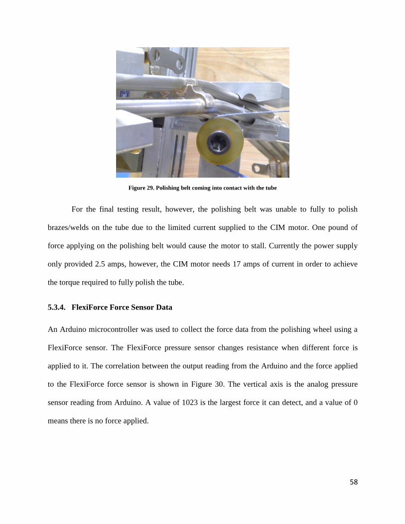
Figure 29. Polishing belt coming into contact with the tube ........................................................ 58

x
Figure 30. Output reading from Arduino vs. force applied to the force sensor ............................ 59
Figure 31. Resistance-force plot of FlexiForce sensor ................................................................. 60
Figure 32. Arduino Uno microcontroller ...................................................................................... 60
Figure 33. High level electrical connections schematic ................................................................ 62
Figure 34. Force sensor circuit...................................................................................................... 63
Figure 35. H-Bridge for controlling linear driving motor ............................................................. 64
Figure 36. The pneumatic tubing. ................................................................................................. 65
Figure 37. Top view of the work cell ............................................................................................ 67

xi
Table of Tables
Table 1. Design metrics for EOAT ............................................................................................... 31
Table 2. Design metrics for polishing methods ............................................................................ 45
Table 3. Actual polishing force and its removal results................................................................ 53

1
1. Introduction
Industrial robotics was founded on the principals that any dull, dirty, or dangerous job repeated
in large quantities should be done by a machine. For a human to repeat a substantial amount of
work would not only bring down efficiency of the production, but also lower the expected
quality of the outcome. Industrial robots are widely used in the manufacturing sector, especially
with batch production. Since the introduction of robotic labor into the manufacturing industry,
development of robotic technologies has grown exponentially due to fast growing needs. GE
Aviation, one of General Electric’s divisions, manufactures a variety of jet engines. Currently,
GE Aviation utilizes a mix of manual and automated manufacturing methods to produce
components for aircraft engines. Some of these components are comprised of a large variety of
tube assemblies of varying dimensions.
During tube manufacturing, the tubes are joined through welding or brazing. The welded
or brazed unions on these tube assemblies affect the performance of the engines. During welding
or brazing processes, discolorations and various types of discontinuities are formed on the
surface of the tubes. Cumulative discontinuities inevitably increase the mass of the tubes and
potentially increase the rate of corrosion. Aside from performance degradation, discoloration
decreases the aesthetics of the tubes, which leaves a bad impression for the customers. GE
Aviation invests a significant amount of manual labor on polishing these brazed or welded parts
to meet the quality specifications of these tubes.
Currently, a manual polishing process is being used at the GE Aviation Hooksett site. The
tube is held by the worker using two hands so that the brazed or welded unions to be polished are
in between where the tube is gripped. The worker then rotates the tube and polishes the brazed or

2
welded areas by using a spinning polishing wheel. After the brazed or welded areas are polished,
the worker manually examines the polished part and decides if further polishing is needed. This
process is time consuming, tedious and potentially unsafe for the workers. Since a large quantity
of tubes needs to be polished each day, GE Aviation decided to investigate the viability of a
robotic system that could polish these tubes automatically.
The goal of this project was to create a robotic process capable of polishing the brazed or
welded areas on the tube supplied by GE Aviation. The project included two key areas of
development: an end-of-arm-tooling for manipulating tubes, and a method for polishing.
Once the entire project is fully developed and implemented, it will bring benefits to the
GE Aviation plant in Hooksett, New Hampshire. This automated system will add a higher level
of precision and consistency to the polishing process and allow the workers who are currently
manually polishing the tubes to be assigned to more important tasks that cannot be automated.

3
2. Background
This chapter provides background regarding the GE Aviation and their current tube polishing
methods, industrial robotics and end-of-the-arm tooling, tube welding and brazing techniques,
and methods for inspecting tube welds and brazes.
2.1. GE Aviation
GE Aviation was founded during World War I and has been an aviation powerhouse ever since.
They have a reputation for introducing innovative parts and assembly processes to the world of
aviation. Currently, GE is leading the world in producing large and small jet engines for
commercial and military aircraft. GE currently has five different types of facilities:
Manufacturing, Overhaul, Accessories, On-Wing Support, and Component Repair. Each facility
is in charge of a different process in the construction of the engine [1].
2.2. Manufacturing Materials Processes: Brazing and Welding
The joining of two metals is a fundamental concern of the manufacturing and materials
processing found in many industrial applications. Two common methods of joining materials are
through the processes of brazing and welding.
Brazing is a metal-joining process [2]. This process consists of heating a filler metal until
the point of melting, whereby it is introduced between two main metal pieces to be joined. The
melted filler metal then, through the ability of capillary action, is drawn up a narrow channel
between the two main pieces of metal. This brazing process often leaves left over residue in the
form of solidified filler material.

4
In typical aircraft applications of industrial welding, a part, usually made from aluminum,
is subjected to welding to either produce a desired assembly or for repair. Methods for welding
aluminum vary, but one method of one of the more common methods is the Gas Tungsten Arc
Welding method (GTAW) also referred to as the TIG (Tungsten Inert Gas) welding process.
2.2.1. Brazing Process
When considering the brazing process, one must consider the selection of materials before any
procedure is implemented. The importance of material selection is weighed based on the filler
material as well as the Base-metal characteristics. In the case of the filler material it has to have
certain attributes that make it appropriate for its intended usage.
Filler metal characteristics include:
1. Limited Reaction with the base metal:
The Material should not produce a chemical reaction with the base-metal.
Chemical reactions usually include a precursor for discontinuities in the
workpiece or areas of contamination.
2. Workable Temperature Ranges:
Capable of melting at temperatures comparably lower than the base-metal to
prevent undesired change to the base-metal,
Capable of flowing in its molten state, and
Able to cool evenly and rapidly without cracks or distortions.
Base metal characteristics include:
1. The Stronger, the Better:

5
The base-metal is ultimately what the joining process attempts to make into one
continuous piece; this selection quality usually is common or widespread in practice.
If the base-metal is not inherently a strong metal, but a hardenable metal, it might
form fairly unpredictable stress cracks or discontinuities during the brazing process
with the filler metal throughout the heating and cooling sub-processes.
2. Brazing Occurs Last:
It is recommended that the base-metal not be cold-worked.
Annealing is a by-product of the brazing process, and it is again recommended not to
provide any further working to the metal to prevent discontinuities from forming.
Metal selection is limited to oil-quenched, hardenable air-quenched, and
precipitation-quenched metals, so long as the solution treatment occurs at the same
time as the brazing.
2.2.2. GTAW Process
The GTAW process is a very difficult welding process first developed in the late 1950s as a
variant on popular inert gas methods using argon and helium as a gas medium but with a non-
consumable tungsten electrode to produce the weld. Operation of a proper TIG welder requires
an electrical arc hot enough to melt the affected area of a work metal with the option of inserting
a filler material or combining two heated pieces of a material. This electrical arc is created by a
high frequency generator that provides the electric spark and is shielded in an inert gas to prevent
oxidation of the material. The GTAW process, shown in Figure 1, for welding aluminum
consists of a proper workspace, proper welding controls, and an experienced and patient welder.

6
A proper GTAW workspace requires:
1. Proper Current Selection and Generation: It is suggested that for every 0.001 inch of
thickness of aluminum being melted, an ampere of current is required. A 1/8 inch thick
piece of aluminum being melted can require up to 125 A of current.
2. Gas Selection and Flow Rate: Typically argon is the selected inert gas, but
combinations of argon and helium can be chosen for thicker work pieces. Typically a gas
feed rate of about 15-20•ft3/hr is chosen, with additional increments of 5•ft
3/hr if needed.
3. Tungsten Type and Diameter: Normal aluminum applications call for pure tungsten
electrodes, however, on welds thinner than 0.09 inch modifications of the electrode can
be made implementing a composite electrode. The diameter is chosen based off
Tungsten’s current-carrying capacities. The typical Diameter to Ampere ratio is 0.093
inches to 200 Amps.
4. Proper Filler Material: Filler material should have matching qualities to the work
material.
5. Frequency Control: High Frequency AC is required in order to create a constant bridge
between the workpiece and the electrode. Because high frequency emissions interfere
with modern electronics, it is important to place the grounding clamp as close to the weld
as possible.

7
Figure 1. Image of a Gas Tungsten Arc Weld (GTAW) setup.
The GTAW (TIG) process is notably used in the aerospace industry for thin, nonferrous
materials such as lightweight aluminum because of its ability to require minimal filler material,
and the resulting welds are resistant to corrosion and cracking over long periods.
2.3. Brazing & Weld Analysis and Problems with Brazes and Welds
During the welding process, weld discontinuities and discolorations may occur [3]. The
following provide the causes, issues, and removal process for weld discontinuities and
discolorations.
1. Discontinuities
Cause: The welding process, poor weld joint design, improper welding technique
or application, and inferior quality base metal or filler metal can all contribute to
discontinuities of the tube welds.
Issues: Discontinuities add additional weight to the tube, and may lead to faster
corrosion.

8
Removal process: Discontinuities are mechanically removed first then
chemically treated with a passivation treatment to ensure all corrosion has been
removed.
2. Discolorations
Cause: If the tube is not properly shielded or purged with inert gas or flux during
welding process, discoloration will occur. Typical welding-grade argon is 99.985%
pure. Figure 2 shows the results from different amounts of oxygen in the argon
purging gas. The more oxygen that is contained in the inert gas, the more
discoloration will occur on the tube [4].
-
Figure 2. Discolorations on a welded tube
Weld 1 was made with 0.001% oxygen, weld 4 was made with 0.01% oxygen, and weld 7 was made with 0.1% oxygen.
Issues: Discolorations will cause the surface to be less corrosion resistant. From a
customer’s standard, the more discolorations the tube has, the less desirable the
product is.
Removal process: Mechanical or chemical cleaning followed by a passivation
treatment.

9
2.4. Computer Vision
Computer vision systems can be used to detect the brazed locations on a tube due to the
discoloration caused by the braze filler material and the discontinuous surface characteristics.
The typical discoloration of a tube from GE Aviation is shown in Figure 3.
Figure 3. Discoloration on the tube supplied by GE
2.4.1. Computer Vision Software
There are several existing software packages that can used to detect changes in color, changes in
the surface texture, and obvious discontinuities in the shape of the tubes: Open Source Computer
Vision Library (OpenCV), CMVision and Matlab Image Processing Toolbox.
OpenCV is an open source computer vision software library. The library has more than
2500 algorithms that can be used to detect and recognize faces, identify objects, classify human
actions in videos, track movements, and track objects. For color recognition, OpenCV provides
the ability to process real time images collected from the camera. When the image is loaded, a

10
2D array of the image can be generated with RGB values representing the colors of each pixel.
Users can manipulate and extract color-based data from the image [5].
CMVision is open source software developed by Carnegie Mellon University. It can
create simple, robust vision systems suitable for real time robotics applications. The system aims
to perform global low level color vision at video rates without the use of special purpose
hardware. Images can be processed using color-based threshold classification [6].
Matlab is a high-level language and interactive environment for numerical computation,
visualization, and programming. Users can analyze data, develop algorithms, and create models
and applications using Matlab [7]. Matlab provides an Image Processing Toolbox that contains a
comprehensive set of reference-standard algorithms and graphical tools for image processing,
analysis, visualization, and algorithm development. Users can perform color-based
manipulations using Matlab Image Processing Toolbox [8].
2.4.2. Computer Vision Implementation – Manipulator Control
Manipulator control for robot arms is often assisted by a computer vision system. The camera
can be used to determine the position and orientation of a given object. The camera used for the
computer vision can either be placed so that it overlooks the work cell from a fixed location or
the camera can be placed on the end of the robot arm, or a combination of the two cameras. An
end-effecter mounted camera can either be placed so that it can see the tooling and the object or
so that the camera only sees the object. The way the camera is mounted depends on the
requirements of the task of the tooling and the way vision sensing and force sensing interact to
control the system.

11
Integrated force sensing and vision for control can come in several forms: traded, hybrid,
and shared control. Traded control is when the direction of the manipulator is only being
controlled by one method, either vision or force sensing, at a time. Hybrid control is when vision
and force sensing control different directions of motion at the same time. Shared control is when
vision and force sensing control a single manipulator direction simultaneously.
2.5. Robots in Manufacturing
Modern robots can be used to perform many tasks. For example, most industrial robots can be
programmed to polish, mill, deburr, drill or cut material. Robots are chosen to complete these
tasks over conventional machining tools because they have higher precision and flexibility than
conventional machines. The reason why modern robots are much more advanced in automation
is due to the utilization of sensors and software control. The sensors and software give the robot
information about its surroundings and a better understanding of its tasks. Modern robots allow
the operators to dictate how much force the robot will use and also control how fast the robot
will maneuver. This gives them the ability to complete production more accurately and at a faster
rate than if there were no sensors deployed to allow for feedback from the environment.
These qualities have propelled modern robots over the conventional machines that were
previously used in manufacturing. Robotics can also potentially make the workspace a safer
place. They eliminate some of the tedious and harmful work that human beings were once
responsible for.
2.5.1. Polishing Robots
Polishing is the process of removing a small amount of material to achieve a smooth finish,
enhance the visual appearance of an item, remove and prevent oxidation, and prevent corrosion

12
of the material. The importance of polishing tubes is to ensure that the airplane meets the
customer’s desired specifications and that each tube is lighter. The polishing process serves also
to eliminate oxidation, discoloration, and other defects that may damage the tubes, thus
shortening its lifetime.
Industrial robots are often utilized to perform the polishing tasks because of their
precision, speed, and repeatability. These robots are arm-shaped and have multiple degrees of
freedom, therefore qualifying achieving high quality of polishing results.
2.5.2. The End-of-Arm-Tooling
The End-of-Arm-Tooling (EOAT), also known as the robot end effector, is the part of a robot
that interacts with the work environment. It is the last link of a serial robotic manipulator and can
be a gripper for picking up and manipulating parts or it could be a specialized tool such as a
welding gun, glue dispenser, or polisher [9].
There are a variety of EOAT’s and the EOAT selection is dependent on the overall
system design and application. Pneumatic grippers are ideal for grabbing an object that is always
the same size because the gripper only needs an open and closed setting. Standard grippers often
have a two-finger or three-finger design and may include force-sensing to provide feedback.
2.5.3. Force Sensing
Force sensing can be accomplished with resistive, capacitive, piezoelectric, or optical sensors
[10].
Resistive sensors measure a change in resistance over the area of a material as it is
deformed. Resistive sensors are small and highly sensitive; however they can be fragile
and costly.

13
Capacitive sensors can detect normal and shear forces by measuring change in
capacitance due to deformation. The sensing capabilities are dependent on the
arrangement of the capacitors and can be very sensitive.
Piezoelectric sensors turn received pressure into an electric voltage and do not require a
power supply in order to function. They are robust and have wide applications, but can
lose voltage output over time.
Optical sensors detect a change in light. The idea behind optical sensors is that an applied
force will change the intensity of light passing through a membrane.
2.6. Polishing Alternative: Sand Blasting/Glass Bead Blasting
GE has provided an assembly that is composed of tubes that have been brazed together. Brazing
is a process used to join metals using a filler metal, typically copper mixed with silver or nickel.
The process of brazing is done with temperatures below the melting point of the base material,
stainless steel.
Due to the complex angles that the tube assembly (shown in Figure 4) contains, certain
areas of the tubes will be complicated to polish. These difficult to polish areas are located in the
center of the brazed unions and would require complex programing that would allow the robot to
maneuver with accuracy within a very small area.

14
Figure 4. Complex-angled tube assembly received from GE Aviation
Due to the brazed portions being so small, there is the potential to utilize sand blasting.
Sand blasting consists of blowing sand particles at a fast rate through a nozzle using water, air, or
steam pressure [10]. This method has been used to polish and cut/carve material, and is a suitable
alternative to a polishing wheel. It allows polishing and cleaning areas that a polishing wheel
could not fit into and has a wider range of flexibility. Sand blasting does present some risks
though, one of which is that it leaves harmful particles in the air [11].
Sand blasting is done in confined and insulated places due to the generation of dangerous
silica particles. These particles can be inhaled and can cause lung problems. Aware of the
dangers, employees should take all necessary precautions by wearing goggles to protect their
eyes and face masks to prevent inhaling the particles. Also wearing protective clothing is
necessary to protect the skin from the particles deflecting backward and hitting the employee
[12]. There is a less risky alternative, though, which is bead blasting with glass beads.
Bead blasting is a more environmentally friendly approach and involves fewer chemicals.
The glass beads used in bead blasting are lead-free and do not contain silica. These glass beads
can be recycled up to 30 times, which is a financial benefit.

15
In terms of performance, bead blasting produces a smoother and brighter finish than sand
blasting. Also glass bead blasting leaves no embedded residue and does not change the surface’s
dimension. Glass bead blasting can also improve corrosion resistance. Glass bead blasting is
used on a wide range of materials including brass, stainless steel, copper, steel, aluminum, etc.
[13]. Because glass beads do not contain silica, the health concern of silica particles in the air is
no longer a safety factor. Therefore glass bead blasting will be easier to implement because
there will not be many extra safety precautions needed.
In terms of cost, glass bead blasting is also a lower cost process than sand blasting.
During the process of sand blasting, the sand is fragile and breaks apart easily. This causes dust
particles to float in the air and causes the health issues for employees. The sand isn’t recyclable
due to breakage, so there will be constant replacement. This constant replacement will add up
and be more expensive than reusable glass beads. Also sand blasting cause changes in the work
dynamic because employees would have to change their clothing and conceal certain areas of
their work stations.

16
3. Methodology
The goal of this project is to automate the polishing process of brazed or welded areas on a tube
assembly supplied by GE Aviation. A statement of work was developed and supplied to GE
Aviation for approval guaranteeing that the concept behind the project was understood: a first
year prototype deliverable to GE capable of polishing braze locations on a specific tube assembly
supplied by GE Aviation. The project included two key areas of development: an end-of-arm-
tooling for manipulating tubes, and a method for polishing.
Background research was accompanied to determine if prior work relevant to the project
was conducted. Topics covering the two key components were researched.
The initial prototype design procedure included brainstorming different methods of
manipulating the tubes, and polishing the tubes. After all the potential methods and EOAT
designs were listed, a design metric capable of narrowing down the selection was created.
Selection of which of the polishing processes, methods, and EOAT design implementations
would be relevant to the scope of the project was made. Though sand blasting, particularly glass
bead blasting, was the most appealing of the polishing methods, it was cost prohibitive and
ultimately eliminated in favor of traditional belt polishing. For all other aspects of the project,
time cost, system precision, functionalities, and complexities were considered in their own
individual metric. The top two or three methods were selected as the final designs. CAD models
and hand drawn sketches were used to create visual representations, and simulations were
conducted to test if the system would meet the project goal. By comparing the final two or three
designs, the most feasible one was chosen as the final decision.

17
The initial components for the gripper design were purchased and an initial prototype of
the grippers was fabricated and further tested. Force calculations were determined using a simple
scale and a square inch of sandpaper of useable grit that would resemble our polishing methods.
The work cell provided by GE Aviation was not usable during the span of the MQP, but an
alternative existing Fanuc robotic arm was used. The pneumatic grippers were purchased from
Schunk. The fingers attached to the grippers of the prototype system were manufactured using
the CNC machines located at WPI. The parts were assembled for testing. Results were collected
as the project progressed.

18
4. System Requirements and Specifications
In this chapter, the following requirements are analyzed:
1. Economic Considerations
2. Safety Considerations
3. Social Impact
4. Use and Importance of Standards
4.1. Economic Considerations
There were two major components in this project that needed economic consideration: the robot
to perform the polishing process and the polisher to perform the polishing and force sensing. The
system was a new design that would be relatively economical to implement as well as
completely modular.
4.2. Safety Considerations
Safety considerations for the tube polishing process are related to the work cell of the robot. The
danger of the polishing process comes from the potential for personnel working near the robot to
be struck by the arm as it moves about its work cell as well as the moving polishing belt/wheel.
This means that personnel must stay outside of the work cell of the robot while it is in operation.
This is accomplished by establishing a safe perimeter around the robot during operation. A
protective box should surround the robot in order to establish a safe work cell perimeter. Safety
locks should be connected to the control system. When doors are open or not locked, the system
should automatically stop operating. The robot should always be powered down when

19
performing maintenance on either the robot or the polishing wheel and personnel should not
enter the protective box around the robot while it is in operation. The aforementioned
precautions will help maintain a safe work environment near the work cell of the robot as it
performs its polishing task.
4.3. Social Impact
As robots become more advanced, more tedious and less desirable jobs will be able to be
accomplished by robots instead of human employees. This will increase efficiency in the
workplace and release the employees from undesirable working conditions. In this case, human
employees will be able to focus more on managerial tasks and some tasks that a robot cannot
achieve.
There are other concerns when considering the removal of a laborer’s position. The
ethical consideration for removal of a laborer’s position based on the company’s desire for more
profitability or reduction in risks and training might be considered by some to be self-serving. It
has a legitimate founding in previous iterations of technology and industry. In just 2009,
Foxconn, the Taiwanese multinational electronics manufacturing company, headquarters was set
to replace millions of workers with more than 1 million robotic stations over the span of 3 years
[15]. There was a concern if the replacing of all these jobs was ethical or even advisable, since
the profits and savings could be overshadowed by the negative image the public would perceive
this replacement to be. Some other concerns included the possibility of hostile work
environments, sabotage being one of those issues.

20
4.4. Use and Importance of Standards
All tube properties must fall within the purview of the American Society for Testing Materials
(ASTM) standards shown in Appendix A. The standards utilized is for Aerospace Material
Specification (AMS) 5557 – 321 Seamless or Welded Stainless Tubes. Where applicable, SAE
(Society of Automotive Engineers) standards are also followed to ensure the highest quality of
material being produced. Finally, GE Internal specifications are also applied to the tubes.

21
5. System Design and Analysis
This chapter provides the design and analysis of the subsystems of the End-of-Arm-Tooling, the
polishing methods, the polishing routine and programming, the polisher design and force sensing,
the electronics and interface, and the software.
5.1. End-of-Arm Tooling (EOAT)
The robot must be able to pick up the tube to perform the polishing process, thus a robotic
gripper EOAT is required to achieve this task. This EOAT was designed to attach to the Fanuc
M-710iC/50 Industrial Robot. Since the M-710iC/50 Industrial Robot was not fully setup during
the first year of the project, the EOAT was then customized for the Fanuc LR Mate 200iB robot
that WPI already had running.
There are two major requirements for the EOAT:
1. The EOAT must be able to adapt to various shapes of tubes up to a size that a manual
process can achieve
2. The EOAT must not damage the tubes by changing the shapes or over-polishing the tubes.
Two candidate solutions were brainstormed, analyzed and discussed: the Gripper Base and the
Tube Follower.
5.1.1. Gripper Base
The gripper base is a universal design that can change the gripping positions and orientations to
adapt to different shapes of tubes as shown in Figure 5 and Figure 6.

22
Figure 5. Gripper Base used to grab planar, angled, and non-planar tubes
Figure 6. Gripper Base showing multiple degrees of freedom
The Gripper Base has multiple degrees of freedom as each of the joints can rotate or slide
to adapt to the shape of the tube.
Gripper Base Components
The Gripper Base consists of three parts: fingers, linear actuator, and rotating base.
Fingers
The fingers as shown in Figure 7 are attached to a sliding bar. They can rotate to different angles,
and open and close while sliding on a rail from the linear actuator part.

23
Figure 7. Universal fingers for the Gripper Base design meant to clamp and rotate
The fingertips are interchangeable so that customized fingers can be made to adapt to
specific tubes that are not standard sized or shaped.
Linear Actuator
The linear actuator of the Gripper Base is a set of rails allowing the fingers to slide and move up
and down. The two rails are designed to have rack gears so that the attached fingers can move
along them. The rails have linear motions on the both axis. Figure 8 shows the movement of the
linear actuator of the Gripper Base.

24
Figure 8. Gripper Base linear actuator is meant to be capable of a large range of motion
Rotating Base
The rotating base is the final part of the Gripper Base. The rotating base might not be necessary
if there is already an existing degree of freedom of the robot arm that generates the same
rotational motion. The rotating base is shown in Figure 9.
Figure 9. Rotating Base adds a DOF for the gripper for rotational manipulation
Rack Gear for
Fingers Sliding
Rotating Base

25
Feature Analysis
The Gripper Base is designed to intend for handling all regular-sized single-branched tubes of
various shapes within a motion range. The fingers are able to slide to the left and right to grip a
linear tube; the linear actuator is able to move up and down to grip a planar tube in addition to
the finger sliding; the fingers are able to rotate to grip a non-planar tube. Different gripping poses
are as shown in Figure 10.
Figure 10. Depiction of Gripper Base design interacting with a planar tube at different angles
5.1.2. Tube Follower
The second proposed design is the Tube Follower. The Tube Follower is intended to be an
apparatus that encloses the tube. It is intended to move along the tube path and follows the shape
of the tube while using machine vision to identify a weld/braze then polishes it using a built-in
belt.

26
Figure 11. Tube Follower polishes brazes as it crawls along the length singular tubes
Tube Follower Component
The Tube Follower would consist of three parts: the Moving Wheel, the Camera, and the
Polisher. They would all be built on the inside-edge of the Tube Follower.
Moving Wheel
The moving wheel is inside the Tube Follower. The main function of this moving wheel is to
enable the Tube Follower to move along the tube following its shape. When the Moving Wheel
hit a turning point on the tube, it can detect the force on one side thus change the orientation of
the Tube Follower to move along the tube.
Wheels to Move the Tube
Moving Direction
Camera Polisher

27
Camera
A computer vision camera could be embedded inside the Tube Follower to identify the locations
of the welds or brazes.
Polisher
A polisher could be used to perform the polishing process. The tube could be in contact with the
polisher during the polishing process.
Feature Analysis
The Tube Follower is a unique design that is different from traditional industrial robot arm. It
could follow a tube’s shape thus making it easier to perform the polishing process regardless of
the tube shape. The tube follower would be able to handle various shapes and sizes, but its down
side is that it would not be able to handle branches.

28
5.1.3. Design Comparison
The pros and cons for each EOAT design are listed below:
Pros and Cons of the Gripper Base:
Pros:
Multi-purpose design. Can be either mounted on the robot arm or on the table as a
tube fixture
Flexible joints that can adapt to different tubes
Interchangeable fingers
Cons:
Complex design with mutiple DOF
Design Difficulty
Programming complexity
Need to adapt to different shapes of tubes
Mechanical design complexity
Needs numerous actuators to fully control it
Resources
Cost (Budget)
Motors, raw materials, manufacturing and pneumatic grippers
Time cost (for GE)

29
Robot needs to move the tube to different positions for full polishing.
Performance
Precision
Hard to determine and locate the areas that need to be polished
Desired functions absence
No distinct disadvantage
Pros and Cons of the Tube Follower:
Pros:
Different tube shapes become trivial
Using a belt to polish, less potential for damage
A robot arm may not be required
Cons:
Only operates on one branch at a time
Limited Diameter range
Design Difficulty
Programming complexity
Very easy programming by following the path of the tube.
Mechanical design complexity

30
Customized EOAT to perform tube following
EOAT
A circular shape tool with polishing belt, vision system inside.
Resources
Cost (Budget)
Necessary components: Customized EOAT, robotic arm
Time cost (for GE)
Tasks that consume time: picking up the tube, tube following while polishing.
Performance
Precision
With proper control and spot polishing, the system potentially has a very low risk
of damaging the tubes. The system will use polishing belt instead of polisher.
Desired functions absence
Cannot polish branches.
Based on multiple design requirements, the team made a rubric for accessing these two
EOATs. A scale from 1 to 5 was used, where 5 meant the highest penalty. See Table 1 for the
complete design metrics. Based on the penalty score, the Gripper Base design was selected as the
final design prototype.

31
EOAT
Metrics
Gripper Base Tube Follower
Design Difficulty
Programming
complexity
4
Need to adapt to different tubes
2
Mechanical design
complexity
3 5
Highly customized design
Resources
Cost (Budget) 3 4
Highly customized design
Time cost (for GE) 4
May change gripping locations
3
Performance
Precision 4
Harder to determine polish area
3
Desired functions
absence
2 5
Cannot polish branches
Total 20 22
Table 1. Design metrics for EOAT

32
5.1.4. Final Design
A final design was implemented based on the seven-tube assembly shown in Figure 12 supplied
by GE Aviation.
Figure 12. Seven-tube assembly supplied by GE Aviation
Based on the unique shape of this tube assembly, a customized fingertip was designed to
adapt to the specific shape of the tube assembly. The second-phase Gripper Base design is shown
in Figure 13. The fingers have 4 concaved slots to match the side of the tube assembly.
To actuate the fingers, a variety of actuators were considered. Since the fingers only need
two states: open and close, and the force required to keep the tube in the fingers should be large
enough to hold the tube, pneumatic grippers were considered as the best choice. After choosing
the Schunk PGN-125/1 Pneumatic Gripper as the actuator, further redesigning was conducted to
integrate the Schunk gripper and the fingers. A silicone pad was used to prevent potential

33
damage to the tube. One half of the customized finger is shown in Figure 14. Figure 15 shows
how the silicone padding protects the tubes while gripping them securely. An integrated finger
with Schunk gripper is shown in Figure 16.
Figure 13. Second-phase finger design shown gripping the GE tube assembly
Figure 14. Final design of a single unit of the customized finger

34
Figure 15. Implementation of the silicone pad on the finger to disperse contact forces
Figure 16. Pneumatic gripper assembled with redesigned fingers attached
Two half-fingers were combined together as one set on a Schunk PGN 125/1 parallel
gripper to perform the gripping. Two sets of fingers were used to mimic the two hands of a
worker and to secure the orientation of the tube while polishing.
Silicone pad

35
To simplify the Gripper Base as a first-year design, a non-rotational plate with
customized fingers is implemented as shown in Figure 17. The plate is fixed between the robot
and the two Schunk grippers. The linear actuator and rotation base are not implemented. Given
the angle of rotation between the two sets of fingers and the fixed distance between them, there is
only one way to grab the tube assembly.
Figure 17. Complete gripper design with pneumatic gripper, fingers and tube assembly
5.2. Polishing Method
A polishing method is needed to mimic the current manual polishing process used at the GE
Aviation Hooksett site. A polisher design is then needed to perform the polishing process.

36
There were two major requirements for the polishing method and the polisher:
1. The polishing method and polisher must be able fully polish the tube from various angles.
2. The polishing method and polisher must not damage the tube or the robot.
Both the polishing wheel and sand/beads blasting were considered as potential polishing
methods. However, due to the limited work space and testing equipment, neither the sand
blasting nor the glass beads blasting method was further considered, therefore they were not
tested or implemented in this project.
Three final candidate solutions were analyzed and discussed: the Moving Tube Fixed
Polisher, the Moving Polisher Fixed Tube, and the Moving Tube Moving Polisher.
5.2.1. Moving Tube, Fixed Polisher
The Moving Tube, Fixed Polisher means that the robot grabs the tube, holds the tube onto a fixed
polishing wheel, changes polishing angles of the tube until it is polished. The Moving Tube,
Fixed Polisher is as shown in Figure 18.

37
Figure 18. Moving Tube, Fixed Polisher with tube being brought to the polishing station
Feature Analysis
The Moving Tube, Fixed Polisher polishing method features a flexible Gripper Base mounted on
the robot arm, and a stationary polishing wheel fixture on the ground which can sense the force
on the tube while polishing. The robot only needs to pick up the tube from a specified location,
holds it tight, moves to the polisher then starts to polish while moving or rotating the tube as
necessary to polish different areas. After the polishing is completed, the robot will drop off the
tube at another specified location. The next iteration then starts again.
Gripper Base Robot Arm
Polisher

38
5.2.2. Moving Polisher, Fixed Tube
The second design is the Moving Polisher, Fixed Tube. This polishing method is the opposite of
the Moving Tube, Fixed Polisher. The robot arm grabs the tube, passes it to the Gripper Base
fixture, changes the tool from grippers to polishing wheel then starts to polish. The design is
shown in Figure 19.
Figure 19. Moving Polisher, Fixed Tube with tube being fixed on the polishing station
Feature Analysis
The Moving Polisher, Fixed Tube polishing method features a Gripper Base mounted on the
ground or table as a fixture, and a polishing wheel mounted directed on the robot as an EOAT
which can sense the force while polishing. The robot needs to pick up the tube from a specified
Gripper Base
Polisher
Robot Arm

39
location, pass it to the Gripper Base, change the tool to a polishing wheel, then start to polish the
tube on the fixture. After the polishing being completed, the robot will change the tool back to
the gripper, pick up the tube from the fixture, drop off the tube at another specified location, then
change the tool back to grippers. The next iteration then starts again.
5.2.3. Moving Tube, Moving Polisher
The last design combines the first and the second design together. Two robots are designed to be
used to implement this polishing method. One robot holds the tube; the other robot uses a
polisher to polish the tube.
Figure 20. Moving Tube, Moving Polisher with tube and polisher moving at the same time

40
Feature Analysis
The Moving Tube, Moving Polisher polishing method features a Gripper Base mounted on one
robot, and a polishing wheel mounted on the other robot as an EOAT which can sense the force
while polishing. The robot with Gripper Base needs to pick up the tube from a specified location,
and then the robot with Polisher will start to polish the tube. Both robots will move
simultaneously to perform the polishing process. After the polishing is completed, the robot
holding the tube will drop off the tube at another specified location. The next iteration then starts
again.
5.2.4. Design Comparison
The pros and cons for each polishing method design are listed below:
Pros and Cons of the Moving Tube, Fixed Polisher:
Pros:
No need for tool changing
Can pick up the tube then starts to polish immediately
Cons:
EOAT design requires two grippers that can adapt to the tube
EOAT has harder force sensing implementation
Design Difficulty
Programming complexity
Force sensing on the EOAT or Polisher

41
Mechanical design complexity
Gripper mounted to robotic arm, polishing wheel fixed
EOAT
Two mechanical jaw grippers with a force sensor
Resources
Cost (Budget)
Necessary components: gripper base, polishing wheel, robotic arm
Time cost (for GE)
Tasks that consume time: picking up the tube, polishing.
Performance
Precision
Tubes are pressed up against a polisher; force is measured by EOAT (gripper base)
or Polisher
Desired functions absence
No distinct disadvantage
Pros and Cons of the Moving Polisher, Fixed Tube:
Pros:
Fewer kinematics calculations

42
Cons:
Need to change tools several times
Need to precisely pass the tube to the Gripper Base (tube fixture)
Design Difficulty
Programming complexity
Force sensing on the EOAT, needs to pass the tube to gripper base
Mechanical design complexity
Needs tool changing during the process
EOAT
Only a polisher mounted on the robot arm
Resources
Cost (Budget)
Necessary components: gripper base, polishing wheel, robotic arm, tool changer
Time cost (for GE)
Tasks that consume time: picking up the tube, passing the tube to gripper base,
tool changing, polishing.
Performance
Precision
Tubes are pressed up against a polisher; force is measured by EOAT (polisher)

43
Desired functions absence
No distinct disadvantage
Pros and Cons of the Moving Tube, Moving Polisher:
Pros:
Fast, requires no tool change
Cons:
Massive work cell
Two robot arms
Parallel Spatial Awareness sensing
Complicated kinematics
Design Difficulty
Programming complexity
Force sensing for the polisher arm, two separate systems, the grippers and the
polisher, interacting with each other.
Mechanical design complexity
Gripper base and one polisher
EOAT
Tooling requires two mechanical jaw grippers. Also requires one custom spot
polisher with force sensing on the arm.

44
Resources
Cost (Budget)
Necessary components: gripper base, polishing wheel, two robotic arms
Time cost (for GE)
Tasks that consume time: picking up the tube, polishing.
Performance
Precision
Hard to control the forces on both arms.
Desired functions absence
No distinct disadvantage
Based on multiple design requirements, a metric for accessing these three polishing
methods was made. A scale from 1 to 5 was used, where 5 meant the highest penalty. See Table
2 for complete design comparison metrics.
The Moving Tube Fixed Polisher design was selected as the final decision. This was
affected by the fact that only one robot was available and the tool changing process would
introduce more potential problems in the future.

45
Methods
Metrics
Moving Tube,
Fixed Polisher
Moving Polisher,
Fixed Tube
Moving Tube,
Moving Polisher
Design Difficulty
Programming
complexity
3 4
Need to pass the tube
5
Mechanical design
complexity
2 3
Need to change tools
4
EOAT 3
A gripper base
2 4
Resources
Cost (Budget) 2 3
Need tool changer
4
Time cost (for GE) 4 5
Need to pass the tube
3
Performance
Precision 4
Force sensing on a
more complex
EOAT
3 5
Desired functions
absence
2 2 2
Total 20 22 27
Table 2. Design metrics for polishing methods

46
5.2.5. Final Design
After deciding to use the Moving Tube, Fixed Polisher polishing method, a polisher was
designed to implement the polishing task. The polisher design is further discussed in section 5.3.
5.3. Polisher Design and Force Sensing
In this section, the force calculations and the polishing station are introduced.
5.3.1. Polishing Wheel Analysis
The GE Aviation Tube Polishing System is a controllable system made to polish the surface of
the tube assembly against a polishing wheel of a fixed radius. This means that the system is
going to experience contact forces and that there is a possibility of applying too much or too little
force to the tube assembly, either damaging it or reducing efficiency. The torque of the polishing
wheel needs to be calculated in order to determine the force required to fully polish the tube.
Cylinder in Contact with a Fixed Point
When the cylinder-shaped tube contacts a fixed point, torque and force are generated.
Figure 21. Stationary wheel contacting fixed point

47
In Figure 21, is the force on the point, K is the axle load bearing, and is the normal
force. Forces and happened on the outer rim of the wheel. Because the wheel was uniform
and had a load bearing axle, the forces can be represented as occurring off k.
In a static system, since system has no acceleration, the two forces will be equal and
opposite.
Rotating Wheel in Contact with a Fixed Point
The moment of inertia for any cylinder is purely a function of the radius and the mass. Thus,
when describing any polishing system where the force occurs at the outer surface a flat disk can
be used to describe the torque of the system. Here we understand that the cylindrical body has
characteristics length L, mass M, change in volume dV, and change in radius dr.
The equation for moment of inertia is determined as:

48
With the equation for the given density of any given volume as:
The equation for area is given by:
The infinitesimal rate of change in radius is then described in the diagram below
Relating the previous equations back to the density, you solve for the change in mass.
Substituting the change in mass back into the moment of inertia equation you get
∫
A rotating disk spinning with torque T and rotational velocity ω about k in contact with point p is
shown in Figure 22.

49
Figure 22. Rotating flattened cylinder
Given that the normal force for any system is, then the Frictional Force is
Restorative for the system of a rotating disk as well. Assuming as well that the force is tangential,
applied at 90˚, then the equation
,
Reduces to the equation
These series of equations show us that the torque is defined as the relation between the
radius and the force of friction. This will later be used to derive the necessary force required for
material removal.
Measuring Force by Change in Distance
Using it can be asserted that the radius is constant, or that any force causing the radius
to compress produces a negligible amount of deflection, and therefore produces a constant force
on the point. Measuring the forces knowing only the change in position is important for deriving
how fast a system needs to go to produce the adequate force necessary.

50
The frictional forces on any system are as follows.
Knowing the frictional force, we can derive the force exuded by the point P as being opposite to
the normal force FN.
Force of the point is defined then as, where mp is the mass of the pipe and is
acceleration.
Acceleration is understood to be the change in velocity over time, and the velocity is
known to be the change in distance over time. This axiom is represented by the notion of
the and which represents the differentiation of the change of position or the double
differentiation.
)
)
Since the mass of the system, M, is constant therefore the change in position, the
difference of over time is all that is required to measure force at the point, P.
5.3.2. Calculation for Tangential Force on the Polishing Wheel and Tube
The surface polishing forces involved in a specific example related to the project will be
calculated. The parameters are as follows:
Material: Low carbon steel
Wheel diameter (D): 6 inches

51
Rotational speed (N): 3000 RPM
Width of cut (w): 1 in
Depth of cut (d): 0.02 in
Feed rate of the work piece (v): 0.12 in/min
To goal is to calculate the cutting force (the force tangential to the wheel) Fc and the
thrust force (the force normal to the work piece surface) Fn via calculating the Material-removal
rate first.
The material-removal rate (MRR) is given by:
MRR = = =
The power consumed is given by
Power =
where u is the specific energy. For Low-carbon steel, the specific energy is estimated to be
15 .
Power = 15 * 0.0024 =
,
Power =
Since power is defined as
Power = ,

52
where the torque T = and is the rotational speed of the wheel in radians per minute
( ).
It follows that
)
Therefore,
The thrust force, Fn, can be calculated directly; however, it also can be estimated by
noting from experimental data that it is about 30% higher than the cutting force, Fc [16].
Consequently,
Therefore the force required to remove the brazes or welds on the tube is not outside of our
measuring range, which is the 25lb limit for a FlexiForce pressure sensor.
Based on the experiment conducted, the actual force needed is around 1 pound-force. The
data collected are shown in Table 3. The testing was conducted in an attempt to find the best
force applied to a part that would result in a material removal rate of 1mm3/5s. Each pass is to be
considered a 1 second stroke during the testing.

53
P50 Grit A 0801 Polishing Wheel
Force
#Passes
0.2-oz 0.4-oz 0.8-oz 1-lb 2-lb
5 min min med med complete
10 min min med large
15 min min med complete
20 min min complete
25 min min
30 min min
Conclusion Insufficient
force
Insufficient
force
Sufficient Sufficient Sufficient,
damages tubes
min = minimal removal
med = medium removal
large = large removal
Table 3. Actual polishing force and its removal results
In conclusion, when later designing the polishing wheel and force sensor components, a
force of one pound-force was considered as the desired removal force.
5.3.3. Polishing Station
The prototype for the MQP required that the system be capable of providing feedback into the
system to do two things. The first is to realize when the system is providing too much force. The
second is to limit the range of forces on the system to be within acceptable polishing levels. To
do this we had to create a motor mount station and feedback-controlled linear actuator to
increase or decrease the force applied by the system.
Motor Mount Station
For the design specifications presented, the motor needs to be medium-sized and provide enough
torque and RPM. The speed of the motor also needs to be controlled. Because of this, the CIM
Motor, P/N: 217-2000CIM was selected along with a Victor 884 Controller [17]. The motor was

54
housed inside a motor mount (Figure 23) specifically designed to be 11 inches off the ground and
5 inches apart from the polishing station.
Figure 23. Motor mount fixture for holding the CIM motor
Polishing Linear Actuator Station
The linear polishing station is comprised of a housing that can be readily bolted to the floor. The
polishing station is shown in Figure 24. The station makes use of a motor and a screw to linearly
drive a platform, (Figure 25 and Figure 26), up and down to increase, or decrease, the contact
force of any tube on the polishing belt. A FlexiForce pressure sensor is glued to the platform to
measure the force in vertical direction.

55
Figure 24. Linear actuator polishing station with polishing belt
Figure 25. The carriage head housing holds the force sensor

56
Figure 26. Linear driving mechanism
The combined polishing station utilizes both the motor mount housing and the linear
station shown in Figure 27 and Figure 28, as well as an embedded microcontroller to fully
interpret force changes and create a control signal to the polishing station. Since the linear
actuator will move up and down, the tension on the belt is changing due to the movement. A belt
tensioner is installed in between to keep the belt tensioned at all times. The polishing belt coming
into contact with the tube is shown in Figure 29.
Screw
A metal plate that is
threaded in the center
to fit the screw
Motor drives the
screw to rotate to
move the metal plate
Connection lock
between screw
and motor shaft

57
Figure 27. CAD drawing of the polishing station with motor mount and belt.
Figure 28. Actual polishing station
Force
sensor
Linear
actuator
Tension
pulley
Polishing belt
Motor
58
Figure 29. Polishing belt coming into contact with the tube
For the final testing result, however, the polishing belt was unable to fully to polish
brazes/welds on the tube due to the limited current supplied to the CIM motor. One pound of
force applying on the polishing belt would cause the motor to stall. Currently the power supply
only provided 2.5 amps, however, the CIM motor needs 17 amps of current in order to achieve
the torque required to fully polish the tube.
5.3.4. FlexiForce Force Sensor Data
An Arduino microcontroller was used to collect the force data from the polishing wheel using a
FlexiForce sensor. The FlexiForce pressure sensor changes resistance when different force is
applied to it. The correlation between the output reading from the Arduino and the force applied
to the FlexiForce force sensor is shown in Figure 30. The vertical axis is the analog pressure
sensor reading from Arduino. A value of 1023 is the largest force it can detect, and a value of 0
means there is no force applied.

59
Figure 30. Output reading from Arduino vs. force applied to the force sensor
According to a 100lb force sensor resistance-force plot, which is similar to the 25lb force
sensor being used in the project (Figure 31), the force versus resistance relationship is non-linear
below approximately the first one-fifth of its range of measurement. In the plot, the pink line is
the actual typical results and the black one is the theoretical conductance. This is why the data
collected above were not linear. Therefore the force sensor is pre-loaded with an initial pressure
in the Carriage Housing Head (Figure 25) in order to have a linear correlation to detect a 1 pound
force change.
0
0.2
0.4
0.6
0.8
1
1.2
0 20 40 60 80 100 120 140 160
Ou
tpu
t R
ead
ing
fro
m A
rdu
ino
Force Applied (N)
Output Reading from Arduino vs. Force Applied to the Force Sensor

60
Figure 31. Resistance-force plot of FlexiForce sensor
5.3.5. Embedded System for Force Sensing
The Arduino Uno microcontroller board, as shown in Figure 32, was chosen as the embedded
system for the force sensing platform. The Arduino Uno has 14 digital input/output pins which
are handled by an ATmega328 microcontroller at a clock speed of 16MHz. The detailed Arduino
specifications are listed in Appendix B.
Figure 32. Arduino Uno microcontroller

61
The 16 MHz high-speed microcontroller is desired to sample the changes in analog
voltage values and then calculate forces based on the change of those analog values. The digital
input and output pins allow the Arduino system to communicate with the Fanuc robot. With a
high-speech controller, data can be processed faster and communication signals between the
force sensor and the robot will not be delayed.
Feedback Loop for Force Control
The feedback system designed is required to control the polishing wheel to prevent any damage
to the tube assembly. This requires a certain control on the system depending on the sensor
readings. Since the linear motor moves the polishing wheel up and down, the reaction force on
the polishing wheel will become the feedback for the motor itself. When the polishing process
starts, the polishing wheels moves upward until the tube and the polishing wheel are in contact.
The force sensor collects the data and the Arduino compares the data with a threshold value in
the program. Once the desired force is reached, the linear drive will stop moving upward.
5.4. Polishing Routine
The following is the sequence used to accomplish the polishing task:
1. Move to the tube pick up station
2. Extend arm towards the tube.
3. Open gripper.
4. Extend arm and grab tube.
5. Close gripper.
6. Move arm towards polishing wheel.
7. Polish one side.

62
8. Rotate.
9. Polish the other side.
10. Move tube back to the desired drop-off location.
11. Place the tube down
12. Open gripper.
13. Bring Arm back to its initial position.
5.5. Electrical and Hardware Interface
The Tube Polishing System encompasses the communication between the Fanuc robot, the force
sensor, and the Arduino.
The overall interface is shown in Figure 33. The force sensor collects the data and outputs
the sensor signal data through op-amps to the Arduino. The Arduino processes the force signal
then generates PWM signals to control the linear actuator via the H-bridge. Once the desired
force is reached and detected by the force sensor, the Arduino will send a signal to the Fanuc
robot through the NI DAQ. The robot can also send signals back to the Arduino using the DAQ.
Figure 33. High level electrical connections schematic

63
5.5.1. Electronics
An Arduino microcontroller is used to gather sensor data from the force sensor below the
polishing wheel. The force sensor and its signal conditioning circuit are shown in Figure 34. The
gain of the first op-amp is
; the second op-amp has a gain of -1. Therefore the
overall again becomes positive
. The FlexiForce force sensor is connected to a negative
feedback loop to allow for easier linearization. The output from the op-amp circuit is directly
connected to the analog input pin on the Arduino. The Arduino then interprets the signal from
the sensor on a 10-bit scale and then compares the input signal to the previous output signal;
which then determines which direction the motor will be controlled via PWM signal.
Figure 34. Force sensor circuit
After the Arduino takes the signal from the force sensor, it generates a PWM output
signal that can control the linear driving motor. The signal goes through an H-Bridge shown in
Figure 35. The H-Bridge takes 2 PWM signals from the Arduino to control the motor for forward
and reverse movement.

64
Figure 35. H-Bridge for controlling linear driving motor
5.5.2. Pneumatics
The Schunk PGN 125/1 pneumatic actuators connect to the end joint on the Fanuc. The
pneumatic connections are located on the front of the J3 casting. Approximately 1341 mm of
pneumatic tubing was required to reach from the EOAT to the connection spot. Two tubing
splitters were used so that the two actuators would be synchronized to a single robot gripper
movement command. The nominal pressure required for the PNG actuators was 6.0bar. The
PGN actuators were controlled by Robot I/O PIN 1 and 2.

65
Figure 36. The pneumatic tubing.
5.6. Programming and Software
The programming involves two parts: the Fanuc robot programming and the Arduino controller
programming. The Fanuc robot program controlled the positions of the EOAT for each
movement during the whole process. The Arduino program controlled the feedback control from
the force sensor. The Arduino interfaced with the Fanuc during the polishing process to
accomplish the task.
Two pieces of software were required for running the polishing process: an Arduino
program running on the Uno and a program written in Karel (the native language of the Fanuc)

66
to control the robot itself. The Karel program was used to control the movement of the robot
arm as it went through the motions of manipulating and polishing the tube. The Arduino
language (a derivative of C/C++) was used to program the Arduino Uno microcontroller for
interpreting the data from the force sensor on the polishing wheel and control the
communications from/to the robot. The complete Arduino program is documented in Appendix
C, and the complete Fanuc program is documented in Appendix D.
5.7. Work Cell
The work cell consists of a 6400 square inches (80 inches by 80 inches) table with the Fanuc
200iB located in the center. Three additional structures within the work cell were the polishing
station as well as a pick-up stand and drop-off stand for holding the tube. The tube pick-up stand
and polishing station were set up on a removable 2x4 foot platform set within the top of the table.
The drop-off stand was originally going to be set up in the 2x4 foot platform as well, but was
placed on a smaller platform to the side of the robot to allow the arm more maneuverability
between the pick-up stand and the polishing station. The distance from the robot to the main
platform of the work cell is 8.5 inches. The robot can reach up to 30 inches in every direction.
The robot can cover most of the work cell with ease as shown in Figure 37.

67
Figure 37. Top view of the work cell
In a real work environment, the work cell layout would be altered to better fit an
automated environment where a conveyor system would either position the tube at the pick-up
position and/or a receiver conveyor system at the drop off station. An alternative to this would be
a hopper/lift system that would deposit the tubes right on the pickup station and another bay that
would receive the tube assemblies. In this current implementation, the pickup would either have
to be singular a person manually adding tube assemblies to the tube stand and removing the
polished tube from the drop off location or further expanded with a multi-tiered pickup with
locations referred to by indices in the code.

68
6. Conclusion
As a result of the project, EOAT designed specifically for the seven-tube assembly was
manufactured and mounted on the Fanuc LR Mate 200iB robot. This EOAT could grip the tube
assembly without damaging it. The tube could be held tight between the fingers in order to
perform polishing process. The Fanuc robot was able to maneuver the tube from pick up station
to polishing station then to the drop off station. A polishing system with force sensor capability
was created. The polishing system was able to detect the force acting on the polishing belt. The
polishing belt was unable to fully to polish brazes/welds on the tube due to the limited current
supplied to the CIM motor. Slight polishing results could be achieved through the polishing
system.

69
7. Future Work
One of the intended future steps for this project is to implement a computer vision system to
detect the shape of a tube so that the robot knows how and where to grasp the tube with the
manipulator, to identify the brazed locations on the tube, and to determine whether the
brazes/welds have been sufficiently polished. Computer vision software can be used to recognize
the features of the tube shape therefore determine the grasp positions. Detecting the
discolorations on the tube would therefore determine the locations of brazes/welds and determine
whether further polishing is needed.
Another possible augmentation to incorporate into the design of the robot would be touch
sensing in the fingers of the EOAT. Touch functionality would assist in the ability to handle
various tube shapes and would work in conjunction with the vision system. Once the robot has
identified where to grasp a section of tubing and moved the EOAT into place then the touch
sensing will control how tight of a grip to use.
The polishing station can be revised to a more stable system. Inside the Fanuc work cell
sits an existing polishing belt with the force sensor built into the gripper can be implemented.

70
8. Reference
[1] GE Aviation. The History of Aircraft Engines. Available:
http://www.geaviation.com/aboutgeae/history.html, date accessed 4/22/2013.
[2] M. M. Schwartz. Brazing, 2nd Edition. Materials Park, OH. ASM International, 2003.
[3] R. Campbell. Avoiding defects in stainless steel welds. Welding Journal 86(5), pp. 56-63.
2007.
[4] AWS D18.1:1999. Specification for welding of austenitic stainless steel tube and pipe
systems in sanitary (hygienic) applications. American Welding Society, 1999.
[5] OpenCV.org. About. Available Online: http://opencv.org/about.html, Accessed 4/22/2013.
[6] J. Bruce, "The CORAL Group's Color Machine Vision Project," V2.1 ed, 2004.
[7] Mathworks.com. Matlab Overview. Available Online:
http://www.mathworks.com/products/matlab/, Accessed 4/22/2013.
[8] Mathworks.com. Image Processing Toolbox Overview. Available Online:
http://www.mathworks.com/help/images/product-description.html, Accessed 4/22/2013.
[9] G. Monkman, S. Hesse, R. Steinmann, and H. Schunk. Robot Grippers, John Wiley &
Sons, 2007.
[10] H. Yousef, M. Boukallel and K. Althoefer. Tactile sensing for dexterous in-hand
manipulation in robotics—A review. Sensors & Actuators: A.Physical 167(2), pp. 171-187.
2011.
[11] J. D. Meeker, P. Susi and A. Pellegrino, Comparison of Occupational Exposures Among
Painters Using Three Alternative Blasting Abrasives. Journal of Occupational and
Environmental Hygiene 3:9, pages D80-D84, 2006
[12] A. Hubbs, M. Greskevitch, E. Kuempel, F. Suarez and M. Toraason, Abrasive Blasting
Agents: Designing Studies to Evaluate Relative Risk. Journal of Toxicology and
Environmental Health, Part A 68:11-12, pages 999-1016, 2005
[13] M. Ellen Flanagan, N. Seixas, P. Becker, B. Takacs and J. Camp, Silica Exposure on
Construction Sites: Results of an Exposure Monitoring Data Compilation Project. Journal
of Occupational and Environmental Hygiene 3:3, pages 144-152, 2006
[14] R.C. Mulhall, N. D. Nedas, Impact blasting with glass beads, Volume 105, Issue 10, Pages
65–71, 2007
[15] Shenzen, "Foxconn to replace workers with 1 million robots in 3 years," Xinhuanet News,
pp. 1, 2011.
[16] S. Kalpakjian, S. Schmid. Manufacturing Engineering & Technology. Prentice Hall, 2010,
pp. 727 – 730.
[17] VEX Robotics. CIM Motor. Available: http://www.vexrobotics.com/217-2000.html, date
accessed 4/22/2013.

71
Appendix A. Standards
1. ASTM Standards
1.1. ASTM A 262 - This specification covers the standard practices for detecting susceptibility
to intergranular attack in austenitic stainless steels. These practices include five
intergranular corrosion tests.
1.2. ASTM A 370 – Provides testing methods for the specified mechanical properties of steel,
stainless steel, and related alloys. This is a legally binding contract of regulation for the
quality of product that must exist before transfer of product is allowable. Properties tested
include: Tension, Bend, Hardness (Brinell and Rockwell scales), Portability, and Impact
Resistance.
1.3. ASTM E 122 – This practice is intended for use in determining the sample size required
to estimate, with specified precision, a measure of quality of a lot or process.
1.4. ASTM E 353 – These test methods for the chemical analysis of metals and alloys are
primarily intended as referee methods to test such materials for compliance with
compositional specifications, particularly those under the jurisdiction of ASTM
Committee A1 on Steel, Stainless Steel, and Related Alloys.
1.5. ASTM E 426 – Eddy-current testing is a nondestructive method of locating
discontinuities in a product. Changes in electromagnetic response caused by the presence
of discontinuities are detected by the sensor, amplified and modified in order to actuate
audio or visual indicating devices, or both, or a mechanical marker.
1.6. ASTM E 1417 - Establishes the basic parameters for controlling the application of the
liquid penetrant method in ASTM E 426.

72
2. SAE Standards
2.1. AMS 2243 – Specification that covers corrosion and heat-resistant steel in the form of
seamless or welded drawn tubing.
2.2. MAM 2243 – Same AMS 2243
2.3. AMS 2248 - Chemical Check Analysis Limits, Corrosion and Heat-Resistant Steels and
Alloys, Maraging and Other Highly-Alloyed Steels, and Iron Alloys
2.4. AMS 2371 - Quality Assurance Sampling and Testing, Corrosion and Heat-Resistant
Steels and Alloys, Wrought Products and Forging Stock
2.5. AMS 2634 - Ultrasonic Inspection, Thin Wall Metal Tubing
2.6. AMS 2807 - Identification, Carbon and Low-Alloy Steels, Corrosion and Heat-Resistant
Steels and Alloys, Sheet, Strip, Plate, and Aircraft Tubing

73
Appendix B. Arduino Specifications

74
Appendix C. Program for Arduino
#define REVERSE_PIN 6
#define FORWARD_PIN 5
#define MOTORPIN 8
#include <Servo.h>
Servo myservo;
//the pin for informing the robot during polishing process
int informPin1 = 13;
// select the input pin for the first force sensor
int sensorPin1 = A0;
// select the input pin for the first force sensor
int flagPin1 = 2;
// variable to store the value coming from the sensor
int sensorValue1 = 0;
int sensorValue = 0; //senfor value
// the input value responding to 1 lbf to polish
int grindingForce = 5;
int offset = 590; //offset for 0 force
int initVal = 0; //initial value for each time of starting
//flag received from robot: 0 waiting, 1 starting to polish
int flag = 0;
//informs robot: 0 means polishing, 1 means stop
int inform = 0;
int currentForce = 0; //stores current force (difference
between current sensor data and init data
void setup(){
Serial.begin(9600);
pinMode(REVERSE_PIN, OUTPUT);
pinMode(FORWARD_PIN, OUTPUT);
pinMode(sensorPin1, INPUT);
pinMode(flagPin1, INPUT);
pinMode(informPin1,OUTPUT);
myservo.attach(MOTORPIN,1000,2000);
}
void loop() {
myservo.write(108);
sensorValue = analogRead(sensorPin1);
flag = digitalRead(flagPin1);
delay(10);
currentForce = sensorValue - offset;
Serial.print(sensorValue);
Serial.print("\t");
Serial.println(currentForce);
//waiting
if(flag == 0)
{
if (currentForce > 20) //some errors margins for zero
force
{
//down
analogWrite(FORWARD_PIN, 255);
analogWrite(REVERSE_PIN, 0);
}
else
{
//stop
analogWrite(FORWARD_PIN, 0);
analogWrite(REVERSE_PIN, 0);
}
inform = 0;//polish not done
}
//polishing
else{
if (currentForce > grindingForce)
{
//stop if force reached to desired level
analogWrite(FORWARD_PIN, 0);
analogWrite(REVERSE_PIN, 0);
delay(500); //right now using timing for polishing
inform = 1; //informs robot polishing completed
}
else
{
//move up
analogWrite(FORWARD_PIN, 0);
analogWrite(REVERSE_PIN, 255);
inform = 0;
}
}
digitalWrite(informPin1,inform);
}

75
Appendix D. Program for Fanuc Robot
/PROG TPSDEMOF
/ATTR
/MN
1:J P[1] 100% FINE ;
2:J P[2] 100% FINE ;
3:J P[14] 100% FINE ;
4: RO[1]=ON ;
5: WAIT 2.00(sec) ;
6:J P[10] 100% FINE ;
7: RO[2]=ON ;
8: WAIT 2.00(sec) ;
9:J P[11] 100% FINE ;
10:J P[4] 100% FINE ;
11:J P[12] 100% FINE ;
12:J P[9] 100% FINE ;
13:J P[18] 100% FINE ;
14: DO[101]=ON ;
15: LBL[1] ;
16: IF DO[101]=ON,JMP LBL[1] ;
17:J P[3] 100% FINE ;
18:J P[19] 100% FINE ;
19:J P[20] 100% FINE ;
20: DO[101]=ON ;
21: LBL[2] ;
22: IF DO[101]=ON,JMP LBL[2] ;
23:J P[21] 100% FINE ;
24:J P[16] 100% FINE ;
25:J P[7] 100% FINE ;
26:J P[6] 100% FINE ;
27:J P[5] 100% FINE ;
28: RO[1]=ON ;
29: WAIT 2.00(sec) ;
30:J P[8] 100% FINE ;
31:J P[17] 100% FINE ;
32:J P[13] 100% FINE ;
/POS
P[1]{
GP1:
UF: 0,
UT: 2,
CONFIG: 'N U T, , 0, 0',
X = 39.449 mm,
Y = 506.402 mm,
Z = 101.224 mm,
W = 1.078 deg,
P = -86.808 deg,
R = -95.479 deg
};
P[2]{
GP1:
UF: 0,
UT: 2,
CONFIG: 'N U T, , 0, 0',
X = -139.977 mm,
Y = 510.634 mm,
Z = 104.465 mm,
W = 5.450 deg,
P = -86.072 deg,
R = -77.704 deg
};
P[14]{
GP1:
UF: 0,
UT: 2,
CONFIG: 'N U T, , 0, 0',
X = -117.897 mm,
Y = 568.715 mm,
Z = -41.775 mm,
W = 7.420 deg,
P = -86.333 deg,
R = -8.503 deg
};
P[10]{
GP1:
UF: 0,
UT: 2,
CONFIG: 'N U T, , 0, 0',
X = -160.328 mm,
Y = 568.713 mm,
Z = -41.783 mm,
W = 7.391 deg,
P = -86.334 deg,
R = -8.474 deg
};
P[11]{
GP1:
UF: 0,
UT: 2,
CONFIG: 'N U T, , 0, 0',
X = -117.897 mm,

76
Y = 586.715 mm,
Z = -41.775 mm,
W = 7.420 deg,
P = -86.333 deg,
R = -8.503 deg
};
P[4]{
GP1:
UF: 0,
UT: 2,
CONFIG: 'N U T, , 0, 0',
X = -117.896 mm,
Y = 441.995 mm,
Z = -39.375.000 mm,
W = 7.420 deg,
P = -86.333.000 deg,
R = -89.310 deg
};
P[12]{
GP1:
UF: 0,
UT: 2,
CONFIG: 'N U T, , 0, 0',
X = 9.704 mm,
Y = 430.555 mm,
Z = 85.585 mm,
W = -3.648 deg,
P = -86.327 deg,
R = -89.669 deg
};
P[9]{
GP1:
UF: 0,
UT: 2,
CONFIG: 'N U T, , 0, 0',
X = 22.904 mm,
Y = 491.275 mm,
Z = 85.585 mm,
W = -3.648 deg,
P = -86.327 deg,
R = -89.669 deg
};
P[18]{
GP1:
UF: 0,
UT: 2,
CONFIG: 'N U T, , 0, 0',
X = 9.704 mm,
Y = 430.555 mm,
Z = 85.585 mm,
W = -3.648 deg,
P = -86.327 deg,
R = -89.669 deg
};
P[3]{
GP1:
UF: 0,
UT: 2,
CONFIG: 'N U T, , 0, 0',
X = 449.588 mm,
Y = 7.600 mm,
Z = 49.505 mm,
W = -3.648 deg,
P = -86.327 deg,
R = -166.954 deg
};
P[19]{
GP1:
UF: 0,
UT: 2,
CONFIG: 'N U T, , 0, 0',
X = 595.347 mm,
Y = 8.400 mm,
Z = -150.575 mm,
W = -3.648 deg,
P = -86.327 deg,
R = -166.954 deg
};
P[21]{
GP1:
UF: 0,
UT: 2,
CONFIG: 'N U T, , 0, 0',
X = 458.707 mm,
Y = 8.400 mm,
Z = -150.575 mm
W = -3.648 deg,
P = -86.327 deg,
R = -166.954 deg
};
P[16]{
GP1:
UF: 0,
UT: 2,
CONFIG: 'N U T, , 0, 0',

77
X = 458.707 mm,
Y = 8.400 mm,
Z = -150.575 mm
W = -3.648 deg,
P = -86.327 deg,
R = -166.954 deg
};
P[7]{
GP1:
UF: 0,
UT: 2,
CONFIG: 'N U T, , 0, 0',
X = 458.707 mm,
Y = 8.400 mm,
Z = -150.575 mm
W = -3.648 deg,
P = -86.327 deg,
R = -166.954 deg
};
P[6]{
GP1:
UF: 0,
UT: 2,
CONFIG: 'N U T, , 0, 0',
X = 458.707 mm,
Y = 8.400 mm,
Z = -150.575 mm
W = -3.648 deg,
P = -86.327 deg,
R = -166.954 deg
};
P[5]{
GP1:
UF: 0,
UT: 2,
CONFIG: 'N U T, , 0, 0',
X = 458.707 mm,
Y = 8.400 mm,
Z = -150.575 mm
W = -3.648 deg,
P = -86.327 deg,
R = -166.954 deg
};
P[8]{
GP1:
UF: 0,
UT: 2,
CONFIG: 'N U T, , 0, 0',
X = 458.707 mm,
Y = 8.400 mm,
Z = -150.575 mm
W = -3.648 deg,
P = -86.327 deg,
R = -166.954 deg
};
P[17]{
GP1:
UF: 0,
UT: 2,
CONFIG: 'N U T, , 0, 0',
X = 458.707 mm,
Y = 8.400 mm,
Z = -150.575 mm
W = -3.648 deg,
P = -86.327 deg,
R = -166.954 deg
};
P[13]{
GP1:
UF: 0,
UT: 2,
CONFIG: 'N U T, , 0, 0',
X = 134.836 mm,
Y = 440.266 mm,
Z = 40.354 mm,
W = -7.357 deg,
P = -87.090 deg,
R = -91.459 deg
};