GE Measurement & Control Solutions Ultrasonic USM Go · PDF fileGE Measurement & Control...
236
GE Measurement & Control Solutions Ultrasonic P/N 1259801 Rev. 5 October 2011 USM Go Operator’s Manual
Transcript of GE Measurement & Control Solutions Ultrasonic USM Go · PDF fileGE Measurement & Control...

GEMeasurement & Control Solutions Ultrasonic
USM GoOperator’s Manual
P/N 1259801 Rev. 5October 2011


USM GoUltrasonic Flaw Detector
Operator’s Manual
P/N 1259801 Rev. 5October 2011
www.ge-mcs.com
©2011 General Electric Company. All rights reserved.Technical content subject to change without notice.

[no content intended for this page - proceed to next page]

Contents
Chapter 1. General Information
1.1 Supplying Power to the Instrument. . . . . . . . . . . . . . . . . . . . . . . . . . . . . . . . . . . . . . . . . . . . . . . . . . . . . . . . . . . . . . . . . . . . . . . . . . . . . . . 21.2 Powering the Instrument ON and OFF . . . . . . . . . . . . . . . . . . . . . . . . . . . . . . . . . . . . . . . . . . . . . . . . . . . . . . . . . . . . . . . . . . . . . . . . . . . . 41.3 Using the Keypad . . . . . . . . . . . . . . . . . . . . . . . . . . . . . . . . . . . . . . . . . . . . . . . . . . . . . . . . . . . . . . . . . . . . . . . . . . . . . . . . . . . . . . . . . . . . 4
1.3.1 Instrument Orientation . . . . . . . . . . . . . . . . . . . . . . . . . . . . . . . . . . . . . . . . . . . . . . . . . . . . . . . . . . . . . . . . . . . . . . . . . . . . . . . . . . 61.3.2 Keypad Components . . . . . . . . . . . . . . . . . . . . . . . . . . . . . . . . . . . . . . . . . . . . . . . . . . . . . . . . . . . . . . . . . . . . . . . . . . . . . . . . . . . . 71.3.3 Joystick Functions . . . . . . . . . . . . . . . . . . . . . . . . . . . . . . . . . . . . . . . . . . . . . . . . . . . . . . . . . . . . . . . . . . . . . . . . . . . . . . . . . . . . . . 81.3.4 Multi-Key Functions . . . . . . . . . . . . . . . . . . . . . . . . . . . . . . . . . . . . . . . . . . . . . . . . . . . . . . . . . . . . . . . . . . . . . . . . . . . . . . . . . . . . 9
1.4 Using the Display . . . . . . . . . . . . . . . . . . . . . . . . . . . . . . . . . . . . . . . . . . . . . . . . . . . . . . . . . . . . . . . . . . . . . . . . . . . . . . . . . . . . . . . . . . . 101.4.1 Accessing the Full-Screen A-Scan Display. . . . . . . . . . . . . . . . . . . . . . . . . . . . . . . . . . . . . . . . . . . . . . . . . . . . . . . . . . . . . . . . . . 111.4.2 Accessing the Acquire Mode Menu . . . . . . . . . . . . . . . . . . . . . . . . . . . . . . . . . . . . . . . . . . . . . . . . . . . . . . . . . . . . . . . . . . . . . . . 121.4.3 Accessing the Setup Mode Menu . . . . . . . . . . . . . . . . . . . . . . . . . . . . . . . . . . . . . . . . . . . . . . . . . . . . . . . . . . . . . . . . . . . . . . . . . 13
1.5 Using the SD Slot, USB Connector & I/O Connector . . . . . . . . . . . . . . . . . . . . . . . . . . . . . . . . . . . . . . . . . . . . . . . . . . . . . . . . . . . . . . . 141.5.1 Removing the SD Card . . . . . . . . . . . . . . . . . . . . . . . . . . . . . . . . . . . . . . . . . . . . . . . . . . . . . . . . . . . . . . . . . . . . . . . . . . . . . . . . . 151.5.2 Inserting the SD Card . . . . . . . . . . . . . . . . . . . . . . . . . . . . . . . . . . . . . . . . . . . . . . . . . . . . . . . . . . . . . . . . . . . . . . . . . . . . . . . . . . 151.5.3 Connecting the USB Port . . . . . . . . . . . . . . . . . . . . . . . . . . . . . . . . . . . . . . . . . . . . . . . . . . . . . . . . . . . . . . . . . . . . . . . . . . . . . . . 161.5.4 Connecting the I/O Port. . . . . . . . . . . . . . . . . . . . . . . . . . . . . . . . . . . . . . . . . . . . . . . . . . . . . . . . . . . . . . . . . . . . . . . . . . . . . . . . . 17
USM Go Operator’s Manual iii
Contents
Chapter 2. Instrument Setup
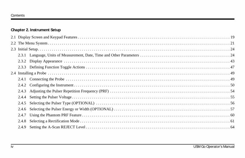
2.1 Display Screen and Keypad Features . . . . . . . . . . . . . . . . . . . . . . . . . . . . . . . . . . . . . . . . . . . . . . . . . . . . . . . . . . . . . . . . . . . . . . . . . . . . 192.2 The Menu System . . . . . . . . . . . . . . . . . . . . . . . . . . . . . . . . . . . . . . . . . . . . . . . . . . . . . . . . . . . . . . . . . . . . . . . . . . . . . . . . . . . . . . . . . . . 212.3 Initial Setup. . . . . . . . . . . . . . . . . . . . . . . . . . . . . . . . . . . . . . . . . . . . . . . . . . . . . . . . . . . . . . . . . . . . . . . . . . . . . . . . . . . . . . . . . . . . . . . . 24
2.3.1 Language, Units of Measurement, Date, Time and Other Parameters . . . . . . . . . . . . . . . . . . . . . . . . . . . . . . . . . . . . . . . . . . . . . 242.3.2 Display Appearance . . . . . . . . . . . . . . . . . . . . . . . . . . . . . . . . . . . . . . . . . . . . . . . . . . . . . . . . . . . . . . . . . . . . . . . . . . . . . . . . . . . 432.3.3 Defining Function Toggle Actions . . . . . . . . . . . . . . . . . . . . . . . . . . . . . . . . . . . . . . . . . . . . . . . . . . . . . . . . . . . . . . . . . . . . . . . . 47
2.4 Installing a Probe . . . . . . . . . . . . . . . . . . . . . . . . . . . . . . . . . . . . . . . . . . . . . . . . . . . . . . . . . . . . . . . . . . . . . . . . . . . . . . . . . . . . . . . . . . . 492.4.1 Connecting the Probe . . . . . . . . . . . . . . . . . . . . . . . . . . . . . . . . . . . . . . . . . . . . . . . . . . . . . . . . . . . . . . . . . . . . . . . . . . . . . . . . . . 492.4.2 Configuring the Instrument . . . . . . . . . . . . . . . . . . . . . . . . . . . . . . . . . . . . . . . . . . . . . . . . . . . . . . . . . . . . . . . . . . . . . . . . . . . . . . 502.4.3 Adjusting the Pulser Repetition Frequency (PRF) . . . . . . . . . . . . . . . . . . . . . . . . . . . . . . . . . . . . . . . . . . . . . . . . . . . . . . . . . . . . 542.4.4 Setting the Pulser Voltage . . . . . . . . . . . . . . . . . . . . . . . . . . . . . . . . . . . . . . . . . . . . . . . . . . . . . . . . . . . . . . . . . . . . . . . . . . . . . . . 552.4.5 Selecting the Pulser Type (OPTIONAL) . . . . . . . . . . . . . . . . . . . . . . . . . . . . . . . . . . . . . . . . . . . . . . . . . . . . . . . . . . . . . . . . . . . 562.4.6 Selecting the Pulser Energy or Width (OPTIONAL) . . . . . . . . . . . . . . . . . . . . . . . . . . . . . . . . . . . . . . . . . . . . . . . . . . . . . . . . . . 572.4.7 Using the Phantom PRF Feature . . . . . . . . . . . . . . . . . . . . . . . . . . . . . . . . . . . . . . . . . . . . . . . . . . . . . . . . . . . . . . . . . . . . . . . . . . 602.4.8 Selecting a Rectification Mode . . . . . . . . . . . . . . . . . . . . . . . . . . . . . . . . . . . . . . . . . . . . . . . . . . . . . . . . . . . . . . . . . . . . . . . . . . . 612.4.9 Setting the A-Scan REJECT Level . . . . . . . . . . . . . . . . . . . . . . . . . . . . . . . . . . . . . . . . . . . . . . . . . . . . . . . . . . . . . . . . . . . . . . . . 64
iv USM Go Operator’s Manual

Contents
2.5 Adjusting the A-Scan . . . . . . . . . . . . . . . . . . . . . . . . . . . . . . . . . . . . . . . . . . . . . . . . . . . . . . . . . . . . . . . . . . . . . . . . . . . . . . . . . . . . . . . . 652.5.1 Setting the A-Scan Range . . . . . . . . . . . . . . . . . . . . . . . . . . . . . . . . . . . . . . . . . . . . . . . . . . . . . . . . . . . . . . . . . . . . . . . . . . . . . . . 652.5.2 Setting the Display Delay . . . . . . . . . . . . . . . . . . . . . . . . . . . . . . . . . . . . . . . . . . . . . . . . . . . . . . . . . . . . . . . . . . . . . . . . . . . . . . . 67
2.6 Calibrating the Instrument . . . . . . . . . . . . . . . . . . . . . . . . . . . . . . . . . . . . . . . . . . . . . . . . . . . . . . . . . . . . . . . . . . . . . . . . . . . . . . . . . . . . 682.6.1 Pre-Calibration Check List . . . . . . . . . . . . . . . . . . . . . . . . . . . . . . . . . . . . . . . . . . . . . . . . . . . . . . . . . . . . . . . . . . . . . . . . . . . . . . 682.6.2 Using AUTOCAL . . . . . . . . . . . . . . . . . . . . . . . . . . . . . . . . . . . . . . . . . . . . . . . . . . . . . . . . . . . . . . . . . . . . . . . . . . . . . . . . . . . . . 692.6.3 Checking the Calibration Results . . . . . . . . . . . . . . . . . . . . . . . . . . . . . . . . . . . . . . . . . . . . . . . . . . . . . . . . . . . . . . . . . . . . . . . . . 72
2.7 Using the Calibration Reminder Alarm . . . . . . . . . . . . . . . . . . . . . . . . . . . . . . . . . . . . . . . . . . . . . . . . . . . . . . . . . . . . . . . . . . . . . . . . . . 732.8 Activating Instrument Upgrades . . . . . . . . . . . . . . . . . . . . . . . . . . . . . . . . . . . . . . . . . . . . . . . . . . . . . . . . . . . . . . . . . . . . . . . . . . . . . . . . 74
Chapter 3. Making Measurements
3.1 Configuring Gate A and Gate B . . . . . . . . . . . . . . . . . . . . . . . . . . . . . . . . . . . . . . . . . . . . . . . . . . . . . . . . . . . . . . . . . . . . . . . . . . . . . . . . 773.1.1 Activating Automatic Gate Threshold (AGT). . . . . . . . . . . . . . . . . . . . . . . . . . . . . . . . . . . . . . . . . . . . . . . . . . . . . . . . . . . . . . . . 773.1.2 Positioning the Gates. . . . . . . . . . . . . . . . . . . . . . . . . . . . . . . . . . . . . . . . . . . . . . . . . . . . . . . . . . . . . . . . . . . . . . . . . . . . . . . . . . . 793.1.3 Selecting the TOF-Detection Method . . . . . . . . . . . . . . . . . . . . . . . . . . . . . . . . . . . . . . . . . . . . . . . . . . . . . . . . . . . . . . . . . . . . . . 833.1.4 Setting Gate Alarms and Outputs . . . . . . . . . . . . . . . . . . . . . . . . . . . . . . . . . . . . . . . . . . . . . . . . . . . . . . . . . . . . . . . . . . . . . . . . . 84
USM Go Operator’s Manual v
Contents
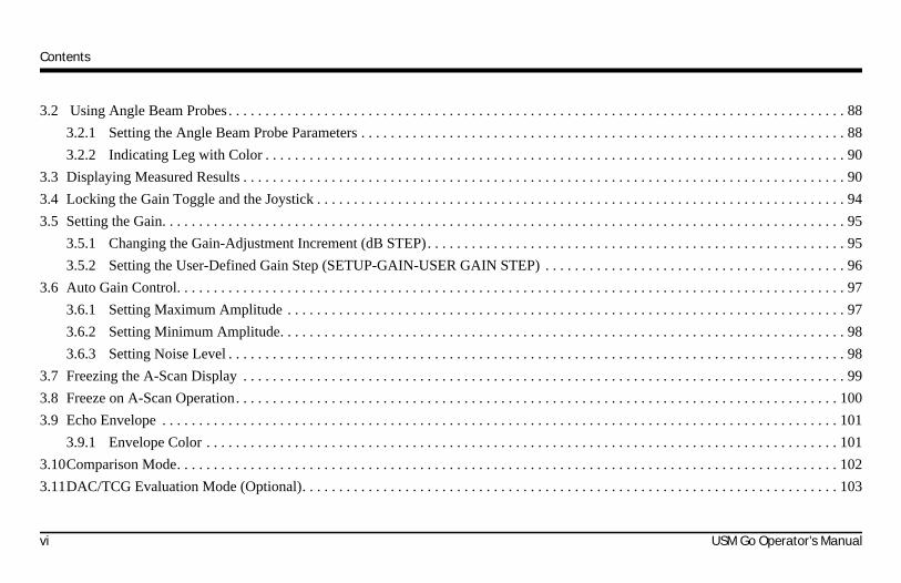
3.2 Using Angle Beam Probes . . . . . . . . . . . . . . . . . . . . . . . . . . . . . . . . . . . . . . . . . . . . . . . . . . . . . . . . . . . . . . . . . . . . . . . . . . . . . . . . . . . . 883.2.1 Setting the Angle Beam Probe Parameters . . . . . . . . . . . . . . . . . . . . . . . . . . . . . . . . . . . . . . . . . . . . . . . . . . . . . . . . . . . . . . . . . . 883.2.2 Indicating Leg with Color . . . . . . . . . . . . . . . . . . . . . . . . . . . . . . . . . . . . . . . . . . . . . . . . . . . . . . . . . . . . . . . . . . . . . . . . . . . . . . . 90
3.3 Displaying Measured Results . . . . . . . . . . . . . . . . . . . . . . . . . . . . . . . . . . . . . . . . . . . . . . . . . . . . . . . . . . . . . . . . . . . . . . . . . . . . . . . . . . 903.4 Locking the Gain Toggle and the Joystick . . . . . . . . . . . . . . . . . . . . . . . . . . . . . . . . . . . . . . . . . . . . . . . . . . . . . . . . . . . . . . . . . . . . . . . . 943.5 Setting the Gain. . . . . . . . . . . . . . . . . . . . . . . . . . . . . . . . . . . . . . . . . . . . . . . . . . . . . . . . . . . . . . . . . . . . . . . . . . . . . . . . . . . . . . . . . . . . . 95
3.5.1 Changing the Gain-Adjustment Increment (dB STEP). . . . . . . . . . . . . . . . . . . . . . . . . . . . . . . . . . . . . . . . . . . . . . . . . . . . . . . . . 953.5.2 Setting the User-Defined Gain Step (SETUP-GAIN-USER GAIN STEP) . . . . . . . . . . . . . . . . . . . . . . . . . . . . . . . . . . . . . . . . . 96
3.6 Auto Gain Control. . . . . . . . . . . . . . . . . . . . . . . . . . . . . . . . . . . . . . . . . . . . . . . . . . . . . . . . . . . . . . . . . . . . . . . . . . . . . . . . . . . . . . . . . . . 973.6.1 Setting Maximum Amplitude . . . . . . . . . . . . . . . . . . . . . . . . . . . . . . . . . . . . . . . . . . . . . . . . . . . . . . . . . . . . . . . . . . . . . . . . . . . . 973.6.2 Setting Minimum Amplitude. . . . . . . . . . . . . . . . . . . . . . . . . . . . . . . . . . . . . . . . . . . . . . . . . . . . . . . . . . . . . . . . . . . . . . . . . . . . . 983.6.3 Setting Noise Level . . . . . . . . . . . . . . . . . . . . . . . . . . . . . . . . . . . . . . . . . . . . . . . . . . . . . . . . . . . . . . . . . . . . . . . . . . . . . . . . . . . . 98
3.7 Freezing the A-Scan Display . . . . . . . . . . . . . . . . . . . . . . . . . . . . . . . . . . . . . . . . . . . . . . . . . . . . . . . . . . . . . . . . . . . . . . . . . . . . . . . . . . 993.8 Freeze on A-Scan Operation. . . . . . . . . . . . . . . . . . . . . . . . . . . . . . . . . . . . . . . . . . . . . . . . . . . . . . . . . . . . . . . . . . . . . . . . . . . . . . . . . . 1003.9 Echo Envelope . . . . . . . . . . . . . . . . . . . . . . . . . . . . . . . . . . . . . . . . . . . . . . . . . . . . . . . . . . . . . . . . . . . . . . . . . . . . . . . . . . . . . . . . . . . . 101
3.9.1 Envelope Color . . . . . . . . . . . . . . . . . . . . . . . . . . . . . . . . . . . . . . . . . . . . . . . . . . . . . . . . . . . . . . . . . . . . . . . . . . . . . . . . . . . . . . 1013.10Comparison Mode. . . . . . . . . . . . . . . . . . . . . . . . . . . . . . . . . . . . . . . . . . . . . . . . . . . . . . . . . . . . . . . . . . . . . . . . . . . . . . . . . . . . . . . . . . 1023.11DAC/TCG Evaluation Mode (Optional). . . . . . . . . . . . . . . . . . . . . . . . . . . . . . . . . . . . . . . . . . . . . . . . . . . . . . . . . . . . . . . . . . . . . . . . . 103
vi USM Go Operator’s Manual
Contents
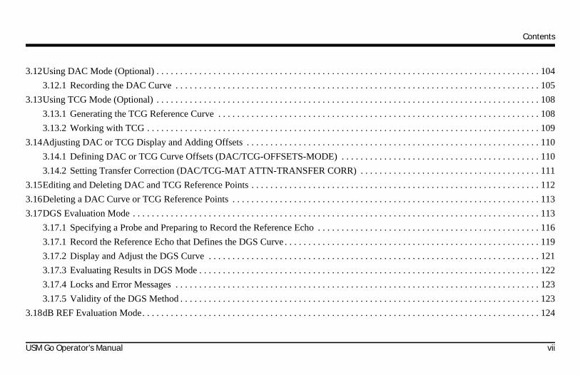
3.12Using DAC Mode (Optional) . . . . . . . . . . . . . . . . . . . . . . . . . . . . . . . . . . . . . . . . . . . . . . . . . . . . . . . . . . . . . . . . . . . . . . . . . . . . . . . . . 1043.12.1 Recording the DAC Curve . . . . . . . . . . . . . . . . . . . . . . . . . . . . . . . . . . . . . . . . . . . . . . . . . . . . . . . . . . . . . . . . . . . . . . . . . . . . . 105
3.13Using TCG Mode (Optional) . . . . . . . . . . . . . . . . . . . . . . . . . . . . . . . . . . . . . . . . . . . . . . . . . . . . . . . . . . . . . . . . . . . . . . . . . . . . . . . . . 1083.13.1 Generating the TCG Reference Curve . . . . . . . . . . . . . . . . . . . . . . . . . . . . . . . . . . . . . . . . . . . . . . . . . . . . . . . . . . . . . . . . . . . . 1083.13.2 Working with TCG . . . . . . . . . . . . . . . . . . . . . . . . . . . . . . . . . . . . . . . . . . . . . . . . . . . . . . . . . . . . . . . . . . . . . . . . . . . . . . . . . . . 109
3.14Adjusting DAC or TCG Display and Adding Offsets . . . . . . . . . . . . . . . . . . . . . . . . . . . . . . . . . . . . . . . . . . . . . . . . . . . . . . . . . . . . . . 1103.14.1 Defining DAC or TCG Curve Offsets (DAC/TCG-OFFSETS-MODE) . . . . . . . . . . . . . . . . . . . . . . . . . . . . . . . . . . . . . . . . . . 1103.14.2 Setting Transfer Correction (DAC/TCG-MAT ATTN-TRANSFER CORR) . . . . . . . . . . . . . . . . . . . . . . . . . . . . . . . . . . . . . . 111
3.15Editing and Deleting DAC and TCG Reference Points . . . . . . . . . . . . . . . . . . . . . . . . . . . . . . . . . . . . . . . . . . . . . . . . . . . . . . . . . . . . . 1123.16Deleting a DAC Curve or TCG Reference Points . . . . . . . . . . . . . . . . . . . . . . . . . . . . . . . . . . . . . . . . . . . . . . . . . . . . . . . . . . . . . . . . . 1133.17DGS Evaluation Mode . . . . . . . . . . . . . . . . . . . . . . . . . . . . . . . . . . . . . . . . . . . . . . . . . . . . . . . . . . . . . . . . . . . . . . . . . . . . . . . . . . . . . . 113
3.17.1 Specifying a Probe and Preparing to Record the Reference Echo . . . . . . . . . . . . . . . . . . . . . . . . . . . . . . . . . . . . . . . . . . . . . . . 1163.17.1 Record the Reference Echo that Defines the DGS Curve . . . . . . . . . . . . . . . . . . . . . . . . . . . . . . . . . . . . . . . . . . . . . . . . . . . . . . 1193.17.2 Display and Adjust the DGS Curve . . . . . . . . . . . . . . . . . . . . . . . . . . . . . . . . . . . . . . . . . . . . . . . . . . . . . . . . . . . . . . . . . . . . . . 1213.17.3 Evaluating Results in DGS Mode . . . . . . . . . . . . . . . . . . . . . . . . . . . . . . . . . . . . . . . . . . . . . . . . . . . . . . . . . . . . . . . . . . . . . . . . 1223.17.4 Locks and Error Messages . . . . . . . . . . . . . . . . . . . . . . . . . . . . . . . . . . . . . . . . . . . . . . . . . . . . . . . . . . . . . . . . . . . . . . . . . . . . . 1233.17.5 Validity of the DGS Method . . . . . . . . . . . . . . . . . . . . . . . . . . . . . . . . . . . . . . . . . . . . . . . . . . . . . . . . . . . . . . . . . . . . . . . . . . . . 123
3.18dB REF Evaluation Mode. . . . . . . . . . . . . . . . . . . . . . . . . . . . . . . . . . . . . . . . . . . . . . . . . . . . . . . . . . . . . . . . . . . . . . . . . . . . . . . . . . . . 124
USM Go Operator’s Manual vii
Contents
3.19AWS D1.1 Weld Rating Evaluation Mode. . . . . . . . . . . . . . . . . . . . . . . . . . . . . . . . . . . . . . . . . . . . . . . . . . . . . . . . . . . . . . . . . . . . . . . 1263.20JISDAC Evaluation Mode . . . . . . . . . . . . . . . . . . . . . . . . . . . . . . . . . . . . . . . . . . . . . . . . . . . . . . . . . . . . . . . . . . . . . . . . . . . . . . . . . . . 128
3.20.1 Recording the JISDAC Curve . . . . . . . . . . . . . . . . . . . . . . . . . . . . . . . . . . . . . . . . . . . . . . . . . . . . . . . . . . . . . . . . . . . . . . . . . . . 1293.20.2 Working with JISDAC . . . . . . . . . . . . . . . . . . . . . . . . . . . . . . . . . . . . . . . . . . . . . . . . . . . . . . . . . . . . . . . . . . . . . . . . . . . . . . . . 1303.20.3 Deleting a JISDAC Curve . . . . . . . . . . . . . . . . . . . . . . . . . . . . . . . . . . . . . . . . . . . . . . . . . . . . . . . . . . . . . . . . . . . . . . . . . . . . . . 133
3.21CNDAC Evaluation Mode . . . . . . . . . . . . . . . . . . . . . . . . . . . . . . . . . . . . . . . . . . . . . . . . . . . . . . . . . . . . . . . . . . . . . . . . . . . . . . . . . . . 1343.21.1 Recording the CNDAC Curve. . . . . . . . . . . . . . . . . . . . . . . . . . . . . . . . . . . . . . . . . . . . . . . . . . . . . . . . . . . . . . . . . . . . . . . . . . . 1343.21.2 Working with CNDAC Curves . . . . . . . . . . . . . . . . . . . . . . . . . . . . . . . . . . . . . . . . . . . . . . . . . . . . . . . . . . . . . . . . . . . . . . . . . . 135
3.22Backwall Echo Attenuation . . . . . . . . . . . . . . . . . . . . . . . . . . . . . . . . . . . . . . . . . . . . . . . . . . . . . . . . . . . . . . . . . . . . . . . . . . . . . . . . . . 1383.22.1 BEA. . . . . . . . . . . . . . . . . . . . . . . . . . . . . . . . . . . . . . . . . . . . . . . . . . . . . . . . . . . . . . . . . . . . . . . . . . . . . . . . . . . . . . . . . . . . . . . 1403.22.2 BW Gain . . . . . . . . . . . . . . . . . . . . . . . . . . . . . . . . . . . . . . . . . . . . . . . . . . . . . . . . . . . . . . . . . . . . . . . . . . . . . . . . . . . . . . . . . . . 141
Chapter 4. Data Sets & Reports
4.1 The FILES Menu . . . . . . . . . . . . . . . . . . . . . . . . . . . . . . . . . . . . . . . . . . . . . . . . . . . . . . . . . . . . . . . . . . . . . . . . . . . . . . . . . . . . . . . . . . 144
viii USM Go Operator’s Manual

Contents
4.2 Working With Data Set Files . . . . . . . . . . . . . . . . . . . . . . . . . . . . . . . . . . . . . . . . . . . . . . . . . . . . . . . . . . . . . . . . . . . . . . . . . . . . . . . . . 1454.2.1 Storing a New Data Set File . . . . . . . . . . . . . . . . . . . . . . . . . . . . . . . . . . . . . . . . . . . . . . . . . . . . . . . . . . . . . . . . . . . . . . . . . . . . 1454.2.2 Recalling a Data Set File . . . . . . . . . . . . . . . . . . . . . . . . . . . . . . . . . . . . . . . . . . . . . . . . . . . . . . . . . . . . . . . . . . . . . . . . . . . . . . . 1474.2.3 Deleting a Data Set File. . . . . . . . . . . . . . . . . . . . . . . . . . . . . . . . . . . . . . . . . . . . . . . . . . . . . . . . . . . . . . . . . . . . . . . . . . . . . . . . 1484.2.4 Editing a Data Set File. . . . . . . . . . . . . . . . . . . . . . . . . . . . . . . . . . . . . . . . . . . . . . . . . . . . . . . . . . . . . . . . . . . . . . . . . . . . . . . . . 149
4.3 Creating a Memo (Smart Notes) . . . . . . . . . . . . . . . . . . . . . . . . . . . . . . . . . . . . . . . . . . . . . . . . . . . . . . . . . . . . . . . . . . . . . . . . . . . . . . . 1504.4 Including a Memo in a Report . . . . . . . . . . . . . . . . . . . . . . . . . . . . . . . . . . . . . . . . . . . . . . . . . . . . . . . . . . . . . . . . . . . . . . . . . . . . . . . . 1524.5 Creating a Report Header . . . . . . . . . . . . . . . . . . . . . . . . . . . . . . . . . . . . . . . . . . . . . . . . . . . . . . . . . . . . . . . . . . . . . . . . . . . . . . . . . . . . 1534.6 Including a Header in a Report . . . . . . . . . . . . . . . . . . . . . . . . . . . . . . . . . . . . . . . . . . . . . . . . . . . . . . . . . . . . . . . . . . . . . . . . . . . . . . . . 1544.7 Creating a Report . . . . . . . . . . . . . . . . . . . . . . . . . . . . . . . . . . . . . . . . . . . . . . . . . . . . . . . . . . . . . . . . . . . . . . . . . . . . . . . . . . . . . . . . . . 1554.8 Storing a Report . . . . . . . . . . . . . . . . . . . . . . . . . . . . . . . . . . . . . . . . . . . . . . . . . . . . . . . . . . . . . . . . . . . . . . . . . . . . . . . . . . . . . . . . . . . 1564.9 Fast Report . . . . . . . . . . . . . . . . . . . . . . . . . . . . . . . . . . . . . . . . . . . . . . . . . . . . . . . . . . . . . . . . . . . . . . . . . . . . . . . . . . . . . . . . . . . . . . . 1574.10Parameters Summary . . . . . . . . . . . . . . . . . . . . . . . . . . . . . . . . . . . . . . . . . . . . . . . . . . . . . . . . . . . . . . . . . . . . . . . . . . . . . . . . . . . . . . . 158
Chapter 5. Data Recorder Files
5.1 Naming the Data Recorder File . . . . . . . . . . . . . . . . . . . . . . . . . . . . . . . . . . . . . . . . . . . . . . . . . . . . . . . . . . . . . . . . . . . . . . . . . . . . . . . 1605.1.1 File Selection Mode. . . . . . . . . . . . . . . . . . . . . . . . . . . . . . . . . . . . . . . . . . . . . . . . . . . . . . . . . . . . . . . . . . . . . . . . . . . . . . . . . . . 1605.1.2 File Naming Mode. . . . . . . . . . . . . . . . . . . . . . . . . . . . . . . . . . . . . . . . . . . . . . . . . . . . . . . . . . . . . . . . . . . . . . . . . . . . . . . . . . . . 161
USM Go Operator’s Manual ix

Contents
5.2 Configuring the Data Recorder File . . . . . . . . . . . . . . . . . . . . . . . . . . . . . . . . . . . . . . . . . . . . . . . . . . . . . . . . . . . . . . . . . . . . . . . . . . . . 1625.3 Creating the Data Recorder File . . . . . . . . . . . . . . . . . . . . . . . . . . . . . . . . . . . . . . . . . . . . . . . . . . . . . . . . . . . . . . . . . . . . . . . . . . . . . . . 1625.4 Viewing the Data Recorder File . . . . . . . . . . . . . . . . . . . . . . . . . . . . . . . . . . . . . . . . . . . . . . . . . . . . . . . . . . . . . . . . . . . . . . . . . . . . . . . 1635.5 Using the Data Recorder File . . . . . . . . . . . . . . . . . . . . . . . . . . . . . . . . . . . . . . . . . . . . . . . . . . . . . . . . . . . . . . . . . . . . . . . . . . . . . . . . . 165
5.5.1 Adding Data and A-Scan Images to a Cell . . . . . . . . . . . . . . . . . . . . . . . . . . . . . . . . . . . . . . . . . . . . . . . . . . . . . . . . . . . . . . . . . 1655.5.2 Previewing A-Scan Images in a Cell. . . . . . . . . . . . . . . . . . . . . . . . . . . . . . . . . . . . . . . . . . . . . . . . . . . . . . . . . . . . . . . . . . . . . . 166
5.6 Live Video Record Files . . . . . . . . . . . . . . . . . . . . . . . . . . . . . . . . . . . . . . . . . . . . . . . . . . . . . . . . . . . . . . . . . . . . . . . . . . . . . . . . . . . . . 1685.6.1 Video Record Temporary Source and Destination . . . . . . . . . . . . . . . . . . . . . . . . . . . . . . . . . . . . . . . . . . . . . . . . . . . . . . . . . . . 1685.6.2 Video Record Mode . . . . . . . . . . . . . . . . . . . . . . . . . . . . . . . . . . . . . . . . . . . . . . . . . . . . . . . . . . . . . . . . . . . . . . . . . . . . . . . . . . 1695.6.3 Video Record Filename. . . . . . . . . . . . . . . . . . . . . . . . . . . . . . . . . . . . . . . . . . . . . . . . . . . . . . . . . . . . . . . . . . . . . . . . . . . . . . . . 1705.6.4 Live Video Record File Record Mode . . . . . . . . . . . . . . . . . . . . . . . . . . . . . . . . . . . . . . . . . . . . . . . . . . . . . . . . . . . . . . . . . . . . 1725.6.5 Live Video Record File Replay Mode . . . . . . . . . . . . . . . . . . . . . . . . . . . . . . . . . . . . . . . . . . . . . . . . . . . . . . . . . . . . . . . . . . . . 174
Appendix A. Specifications
A.1 LCD Display . . . . . . . . . . . . . . . . . . . . . . . . . . . . . . . . . . . . . . . . . . . . . . . . . . . . . . . . . . . . . . . . . . . . . . . . . . . . . . . . . . . . . . . . . . . . . . 177A.2 Connectors . . . . . . . . . . . . . . . . . . . . . . . . . . . . . . . . . . . . . . . . . . . . . . . . . . . . . . . . . . . . . . . . . . . . . . . . . . . . . . . . . . . . . . . . . . . . . . . 178A.3 Pulser. . . . . . . . . . . . . . . . . . . . . . . . . . . . . . . . . . . . . . . . . . . . . . . . . . . . . . . . . . . . . . . . . . . . . . . . . . . . . . . . . . . . . . . . . . . . . . . . . . . . 179A.4 Receiver . . . . . . . . . . . . . . . . . . . . . . . . . . . . . . . . . . . . . . . . . . . . . . . . . . . . . . . . . . . . . . . . . . . . . . . . . . . . . . . . . . . . . . . . . . . . . . . . . 180A.5 Gates . . . . . . . . . . . . . . . . . . . . . . . . . . . . . . . . . . . . . . . . . . . . . . . . . . . . . . . . . . . . . . . . . . . . . . . . . . . . . . . . . . . . . . . . . . . . . . . . . . . . 181
x USM Go Operator’s Manual

Contents
A.6 Memory. . . . . . . . . . . . . . . . . . . . . . . . . . . . . . . . . . . . . . . . . . . . . . . . . . . . . . . . . . . . . . . . . . . . . . . . . . . . . . . . . . . . . . . . . . . . . . . . . . 181A.7 Environmental. . . . . . . . . . . . . . . . . . . . . . . . . . . . . . . . . . . . . . . . . . . . . . . . . . . . . . . . . . . . . . . . . . . . . . . . . . . . . . . . . . . . . . . . . . . . . 182A.8 Protection . . . . . . . . . . . . . . . . . . . . . . . . . . . . . . . . . . . . . . . . . . . . . . . . . . . . . . . . . . . . . . . . . . . . . . . . . . . . . . . . . . . . . . . . . . . . . . . . 183A.9 USM Go Options . . . . . . . . . . . . . . . . . . . . . . . . . . . . . . . . . . . . . . . . . . . . . . . . . . . . . . . . . . . . . . . . . . . . . . . . . . . . . . . . . . . . . . . . . . 184
Appendix B. Environmental Compliance
B.1 Waste Electrical and Electronic Equipment (WEEE) Directive. . . . . . . . . . . . . . . . . . . . . . . . . . . . . . . . . . . . . . . . . . . . . . . . . . . . . . . 188B.2 Battery Disposal . . . . . . . . . . . . . . . . . . . . . . . . . . . . . . . . . . . . . . . . . . . . . . . . . . . . . . . . . . . . . . . . . . . . . . . . . . . . . . . . . . . . . . . . . . . 189
B.2.1 What do the Markings Mean? . . . . . . . . . . . . . . . . . . . . . . . . . . . . . . . . . . . . . . . . . . . . . . . . . . . . . . . . . . . . . . . . . . . . . . . . . . . 189B.2.2 The Risks and Your Role in Reducing Them . . . . . . . . . . . . . . . . . . . . . . . . . . . . . . . . . . . . . . . . . . . . . . . . . . . . . . . . . . . . . . . 190
Appendix C. EN 12668 Specifications
USM Go Operator’s Manual xi

Contents
xii USM Go Operator’s Manual

Preface
Safety Information
Before powering up or operating this instrument, the safety information in this section should be read carefully. This Operator’s Manual should be stored in a safe place for reference.
IMPORTANT: This instrument is to be used only for testing materials in an industrial environment. Any use for medical applications or any other purpose is not permitted.
IMPORTANT: This instrument is waterproof according to IP 67. It can be operated either with batteries or with the power supply unit. The power supply unit meets the requirements of Electrical Safety Class II.
Batteries
For battery operation of this instrument, GEIT only recommends the use of a lithium-ion battery. You should only use the battery recommended by GEIT for operation of this instrument. You can charge the lithium-ion battery either within the instrument itself or with the external battery charger.
IMPORTANT: See “Battery Disposal” on page 189 for instructions on proper battery disposal procedures.
USM Go Operator’s Manual xiii

Preface
Important Ultrasonic Testing Guidelines
Please read the information in this section before using your instrument. It is important that you understand and observe this information to avoid any operator errors that might lead to false test results. Such false results could result in personal injuries or property damage.
Using Ultrasonic Test Equipment
This Operator’s Manual contains essential information on how to operate your test equipment. In addition, there are a number of factors that affect the test results, but a description of all these factors is beyond the scope of this manual. The three most important factors for safe and reliable ultrasonic inspection are:
• Operator training
• Knowledge of special technical test requirements and limits
• Choice of appropriate test equipment
xiv USM Go Operator’s Manual

Preface
Operator Training
The operation of an ultrasonic test device requires proper training in ultrasonic testing methods. Proper training comprises adequate knowledge of:
• The theory of sound propagation
• The effects of sound velocity in the test material
• The behavior of the sound waves at interfaces between different materials
• The shape of the sound beam
• The influence of sound attenuation in the test object and the influence of the surface quality of the test object
Lack of such knowledge could lead to false test results with unforeseeable consequences. You can contact GEIT or NDT societies or organizations in your country (DGZfP in Germany; ASNT in the USA) for information on opportunities for training on ultrasonic instruments that use time-of-flight measurements.
Accurate measurement results require a constant sound velocity in the test object. Steel test objects have only slight variations in sound velocity, thus affecting only high precision measurements. Test objects made of other materials (e.g., nonferrous metals or plastics) may have larger sound velocity variations, which could adversely affect the accuracy of the measurements.
USM Go Operator’s Manual xv

Preface
Test Object Material Effects
If the material of the test object is not homogeneous, the sound waves may propagate at different velocities in different parts of the test object. An average sound velocity should then be used for the range calibration. This is achieved by using a reference block with a sound velocity equal to the average sound velocity of the test object.
If substantial sound velocity variations are expected, then the instrument calibration should be adjusted to the actual sound velocity values at shorter time intervals. Failure to do so may lead to false readings.
Test Object Temperature Effects
The sound velocity also varies as a function of the temperature of the test object. This can cause appreciable errors in measurements if the instrument has been calibrated with a reference block at one temperature, and the instrument is then used on a test object at a different temperature. Such measurement errors can be avoided either by ensuring that the reference block and the test object are at the same temperature, or by using a correction factor obtained from published tables.
xvi USM Go Operator’s Manual

Preface
Limited Warranty
For a period of two (2) years from the date of purchase, we warrant that the instrument will be free of any claim of ownership by third parties, (ii) when new, be free from defects in material and workmanship and perform in accordance with the Product’s specifications under normal use and service for the applicable warranty period following the date of sale. The second year of this warranty is valid only if the instrument is calibrated to within the provided specifications, by us or one of our certified service providers after month twelve of ownership but before month fourteen begins. The duration of the warranty may be extended or modified by explicit service contracts.
This limited warranty shall not apply to any problems arising from (i) failure to follow the product instructions or failure to perform preventive maintenance, (ii) service, repair or modification by someone other than us or one of our authorized service representatives; or (iii) external causes, such as accident, abuse, misuse, or problems with electrical power.
This warranty does not cover parts identified as wear-and-tear parts or lamps, transducers, tubes, accessories, or optional equipment not manufactured by us, which items may be covered by separate manufacturers’ warranties.
Our obligation under this warranty is limited to the repair or replacement of components determined by us to be defective within the warranty period at no cost to the original purchaser. Customer shall arrange for delivery to us in approved packing material. This warranty extends to the original purchaser and cannot be assigned or transferred to any other party.
EXCEPT FOR THE WARRANTY SET ABOVE, WE EXPRESSLY DISCLAIM ALL WARRANTIES AND REPRESENTATIONS OF ANY KIND WITH RESPECT TO OUR PRODUCTS, WHETHER EXPRESS OR IMPLIED, INCLUDING ANY IMPLIED WARRANTIES OF MERCHANTABILITY, FITNESS FOR A PARTICULAR PURPOSE, NON-INFRINGEMENT, TITLE AND ANY WARRANTIES ARISING FROM COURSE OF PERFORMANCE, COURSE OF DEALING OR TRADE USAGE.
USM Go Operator’s Manual xvii

Preface
[no content intended for this page - proceed to next page]
xviii USM Go Operator’s Manual

Chapter 1. General Information
Chapter 1. General Information
The USM Go is a portable ultrasonic flaw detector. In addition to its light-weight design, the USM Go includes a clean and simple user interface and a large, easy-to-read color WVGA (800x480) display. When operating in Acquire Mode, the instrument provides ultrasonic flaw detection and thickness measurements. In this mode, it is capable of storing A-Scans, operating parameters, and reports. Prior to using the Acquire Mode, the instrument display and operating parameters must be configured by using the Setup Mode. The following specific topics are discussed in this chapter:
• Supplying power to the instrument
• Powering the instrument ON and OFF
• Using the keypad
• Using the display
USM Go Operator’s Manual 1
Chapter 1. General Information
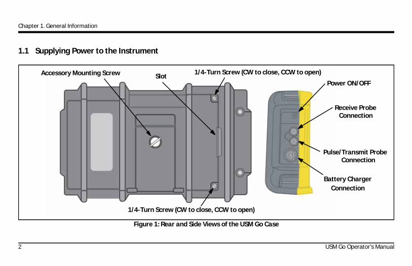
1.1 Supplying Power to the Instrument
Figure 1: Rear and Side Views of the USM Go Case
Accessory Mounting Screw
Battery ChargerConnection
1/4-Turn Screw (CW to close, CCW to open)
Slot
Receive Probe
Power ON/OFF
1/4-Turn Screw (CW to close, CCW to open)
Pulse/Transmit ProbeConnection
Connection
2 USM Go Operator’s Manual

Chapter 1. General Information
1.1 Supplying Power to the Instrument (cont.)
The USM Go can be powered in either of two ways (see Figure 1 on page 2):
• A lithium battery pack that is installed in a compartment on the rear of the case, or
• An external power adapter plugged into the connector on the side of the case
CAUTION! Use only the GE Lithium battery pack in this instrument, and charge only this battery pack in the instrument or in the provided GE charger/adapter.
To remove the battery compartment cover, loosen the two 1/4-turn screws and then lift up on the slot between the screws. The standard GE Lithium battery pack is designed to provide maximum operating life between chargings.
The approximate level of remaining battery life is shown on the display (see Figure 2 on page 5) by the battery icon, , and the approximate “hours of charge” indication below the icon. When a fully-charged battery pack is installed, the icon will appear as “full,” and the icon will begin to “empty” as the battery life is depleted. When the battery indicator is down to one-quarter full, charge the battery pack as soon as possible.
Note: The instrument automatically shuts OFF when the batteries are too weak for reliable operation. However, your settings are saved and then restored when the instrument is turned back ON. When testing in remote locations, always carry a spare battery pack.
USM Go Operator’s Manual 3

Chapter 1. General Information
1.1 Supplying Power to the Instrument (cont.)
When the AC adapter is connected to the instrument, the icon in the upper right corner of the display indicates the percentage of full-charge of the battery pack. When removing the battery pack to install a charged spare, the instrument will automatically turn OFF if the AC adapter is not connected to the instrument. However, if the adapter is connected, the instrument will remain ON while you change battery packs.
1.2 Powering the Instrument ON and OFF
To power the USM Go ON or OFF, simply press the power button, , on the side of the case (see Figure 1 on page 2). As soon as the button press is recognized, you will hear the click of an internal relay. Then, after about 4 seconds, the display controller will be fully loaded and the display will become visible.
1.3 Using the Keypad
The USM Go is designed to provide the user quick access to all of the instrument's functions. Its easy-to-use menu system allows any function to be accessed with a minimum of effort. The functions typically used to collect ultrasonic data are located in the Acquire Mode menu, while those used to configure the instrument are found in the Setup Mode menu.
See Figure 2 on page 5 for the locations of the front-panel components described in this chapter.
4 USM Go Operator’s Manual

Chapter 1. General Information
1.3 Using the Keypad (cont.)
Figure 2: Front Panel of the USM Go
Gain Toggle
Display Screen
Joystick
Battery Indicator
Function Toggle
USM Go Operator’s Manual 5
Chapter 1. General Information
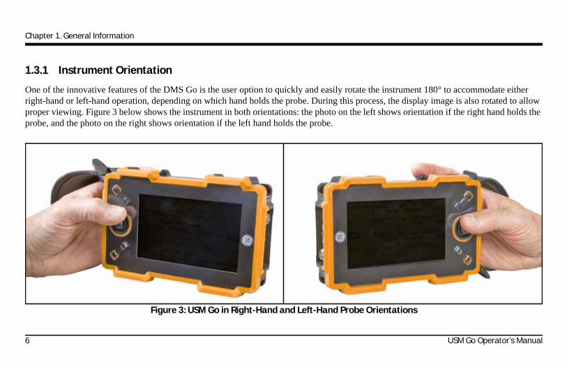
1.3.1 Instrument Orientation
One of the innovative features of the DMS Go is the user option to quickly and easily rotate the instrument 180° to accommodate either right-hand or left-hand operation, depending on which hand holds the probe. During this process, the display image is also rotated to allow proper viewing. Figure 3 below shows the instrument in both orientations: the photo on the left shows orientation if the right hand holds the probe, and the photo on the right shows orientation if the left hand holds the probe.
Figure 3: USM Go in Right-Hand and Left-Hand Probe Orientations
6 USM Go Operator’s Manual

Chapter 1. General Information
1.3.2 Keypad Components
The USM Go keypad includes the following items (see Figure 2 on page 5):
• Center-press joystick ( ): The joystick may be moved either “left or right” or “up or down.” In addition, the center of the joystick may either be “pressed” or “pressed and held.”
• Gain toggle ( ): The two ends of the gain toggle act as separate buttons. One end is the “Gain DOWN” button, while the other end is the “Gain UP” button. Either end of the gain toggle can either be “pressed” or “pressed and held.”
• Function toggle ( ): The two ends of the function toggle act as separate buttons. One end is the “Function 1” button, while the other end is the “Function 2” button. Either end of the function toggle can either be “pressed” or “pressed and held.”
Note: The gain toggle is always at the top of the instrument, and the end of the function toggle closer to the display is always the“Function 1” button, regardless of the chosen instrument orientation.
USM Go Operator’s Manual 7

Chapter 1. General Information
1.3.3 Joystick Functions
The effects of the joystick actions described on the previous page are as follows:
Joystick Center Press:
• When in Acquire Mode, a single press and release ( ) toggles the A-Scan display between standard size and full screen mode.
• When in Setup Mode, a single press and release ( ) activates or deactivates a parameter for adjustment.
• When in Acquire or Setup Mode, a 2-second press-and-hold ( ) switches to the other mode.
Joystick Movement:
• When in Acquire or Setup Mode, moving up/down ( ) scrolls between the available function options for the highlighted menu.
• When in Acquire or Setup Mode, moving left/right ( ) highlights a menu option or adjusts the value of a selected parameter.
8 USM Go Operator’s Manual

Chapter 1. General Information
1.3.4 Multi-Key Functions
Note: All multi-key functions are defined with the instrument in the left-hand orientation (see the left side of Figure 3 on page 6).
• Power button + Function 2 button + Gain DOWN button
Pressing and holding these three buttons simultaneously causes the instrument to initiate a software upgrade.
Note: A formatted SD card with a valid USM Go upgrade file in the root directory must be inserted prior to pressing these buttons.
• Power button + Function 2 button + Gain UP button
Pressing and holding these three buttons simultaneously causes the instrument to ignore the last known setup and revert to the factory default settings.
Important: The last known setup will be overwritten and lost during this process.
• Gain UP button + Gain DOWN button
Pressing and holding the two Gain Toggle buttons simultaneously activates the AUTO80 function for the current Evaluation Mode.
USM Go Operator’s Manual 9

Chapter 1. General Information
1.4 Using the Display
Typical displays for the USM Go Acquire Mode and Setup Mode menus are illustrated in Figure 4 below. See the following pages for step-by-step instructions on accessing these menus.
Figure 4: Acquire Mode (Left) and Setup Mode (Right) Displays
Battery IndicatorGain Window Gate Results
Menu BarParameters Grid Menu BarParameters
Menu Title
10 USM Go Operator’s Manual

Chapter 1. General Information
1.4.1 Accessing the Full-Screen A-Scan Display
When in Acquire Mode, a single press and release of the joystick ( ) toggles the A-Scan display between standard-size and full-screen display mode. When viewing the A-Scan in full-screen mode, the joystick can be used to change the parameters of Gate A, as follows:
Note: If the joystick lock function has been enabled (see “Locking the Gain Toggle and the Joystick” on page 94), any up-down and left-right joystick movements will have no effect on the instrument.
• Moving the joystick left or right ( ) will change the Gate A range in that direction.
• If AGT is OFF, moving the joystick up or down ( ) will change the Gate A threshold, accordingly.
To disable full-screen Gate A control without effecting other instrument functions, activate the JOY CONTROL parameter as follows:
1. In the SETUP menu, activate the CONFIG1 submenu using the joystick ( ).
2. Use the joystick ( ) to select the JOY CONTROL function, and press the center of the joystick ( ) to activate it.
3. Use the joystick to select either the ON or OFF option, and press the center of the joystick ( ) to deactivate the function.
USM Go Operator’s Manual 11
Chapter 1. General Information
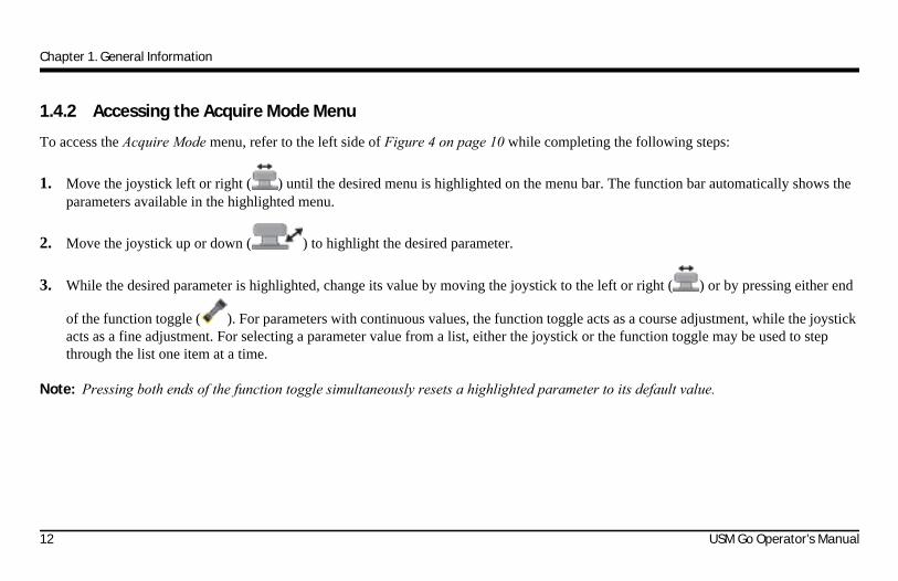
1.4.2 Accessing the Acquire Mode Menu
To access the Acquire Mode menu, refer to the left side of Figure 4 on page 10 while completing the following steps:
1. Move the joystick left or right ( ) until the desired menu is highlighted on the menu bar. The function bar automatically shows the parameters available in the highlighted menu.
2. Move the joystick up or down ( ) to highlight the desired parameter.
3. While the desired parameter is highlighted, change its value by moving the joystick to the left or right ( ) or by pressing either end
of the function toggle ( ). For parameters with continuous values, the function toggle acts as a course adjustment, while the joystick acts as a fine adjustment. For selecting a parameter value from a list, either the joystick or the function toggle may be used to step through the list one item at a time.
Note: Pressing both ends of the function toggle simultaneously resets a highlighted parameter to its default value.
12 USM Go Operator’s Manual

Chapter 1. General Information
1.4.3 Accessing the Setup Mode Menu
To access the Setup Mode menu, refer to the right side of Figure 4 on page 10 while completing the following steps:
1. Press and hold the center of the joystick ( ) to toggle between Acquire Mode and Setup Mode.
2. Move the joystick left or right ( ) until the desired menu is highlighted on the menu bar. The function bar automatically shows the parameters available in the highlighted menu.
3. Move the joystick as required ( ) to highlight the desired parameter.
4. Press the center of the joystick ( ) to activate the highlighted parameter. The parameter value can now be changed either by moving
the joystick ( ) as a fine adjustment or by pressing either end of the function toggle ( ) as a coarse adjustment. Press the center
of the joystick ( ) again to deactivate the highlighted parameter.
Note: Step 4 above applies to the setting of all parameters, except for specifying the actions associated with the function toggle keys. For instructions on configuring these keys, see “Defining Function Toggle Actions” on page 47.
To exit the Setup Menu, press any of the gain keys. (While in the Setup Mode, pressing the gain keys will have no effect on the gain setting.)
USM Go Operator’s Manual 13

Chapter 1. General Information
1.5 Using the SD Slot, USB Connector & I/O Connector
The USM Go uses a standard SD memory card for storing data set files and reports (see “The FILES Menu” on page 144) and for loading an instrument software upgrade (see “Activating Instrument Upgrades” on page 74). The SD card slot is located in a compartment on the top of the instrument, along with a USB connector and an I/O connector (see Figure 5 below).
Figure 5: Top View of USM Go Case
USB Connector
Hinged Cover
SD Card Slot
I/O Connector
14 USM Go Operator’s Manual

Chapter 1. General Information
1.5.1 Removing the SD Card
To remove the SD card from its slot, proceed as follows:
1. Access the SD card slot by pushing on the cover in the direction of the arrow and lifting the hinged cover.
2. Press down of the SD card with your finger and then remove your finger quickly. The SD card will be partially ejected, and you can then grasp it by the edge and slide it completely out of the slot.
1.5.2 Inserting the SD Card
To insert the SD card into its slot, proceed as follows:
CAUTION! Do not force the SD card into the slot if you feel significant resistance. If the card does not enter the slot freely, it is probably oriented incorrectly.
1. Access the SD card slot by pushing on the cover in the direction of the arrow and lifting the hinged cover.
2. Orient the SD card so that the label side faces the rear of the instrument and the blank side with the row of gold-colored electrical contacts faces the display side of the instrument. The edge of the card with the row of gold-colored electrical contacts must enter the slot first.
3. Slide the card fully into the slot and push gently until the card seats into its socket. Then, close the SD card slot cover.
USM Go Operator’s Manual 15
Chapter 1. General Information
1.5.3 Connecting the USB Port
The connector closest to the hinge of the top compartment cover (see Figure 5 on page 14) is a Micro USB port. If you use a standard USB cable to connect the USM Go to a PC (no special drivers are required), the installed SD card will be added to the list of active drives on the PC. You can then perform all normal drive activities, such as copying and deleting files, on the USM Go SD card.
Important: While the USM Go is connected to a PC via the USB port, the instrument will not accept any user input from the keypad. Normal operation resumes as soon as the USB cable is disconnected.
16 USM Go Operator’s Manual

Chapter 1. General Information
1.5.4 Connecting the I/O Port
The connector furthest from the hinge of the top compartment cover (see Figure 5 on page 14) is an I/O port. This port serves a dual role:
• Serial port pins - these are used strictly for factory service diagnostics.
• Sync & Alarm pins - these signals are accessible to the user via a special optional cable.
To use this connector you must order the optional USM Go cable, which is available as P/N 022-510-032. The pin designations for connecting the open end of this cable are listed in Table 1 below:
Table 1: I/O Connector Pin AssignmentsPin # Color Signal
1 Brown +5V2 Red SAP3 Orange Alarm4 Yellow RS232 CTS5 Green RS232 TX6 Blue RS232 RX7 Purple GND
USM Go Operator’s Manual 17

Chapter 1. General Information
[no content intended for this page - proceed to next page]
18 USM Go Operator’s Manual

Chapter 2. Instrument Setup
Chapter 2. Instrument Setup
2.1 Display Screen and Keypad Features
The USM Go user interface has been designed for clarity and ease of use. Figure 6 below show the complete set of icons that may appear in the icon area of the screen, and Figure 7 on page 20 shows the major components of the display and the keypad.
Figure 6: Display Screen Icons
Freeze mode has been activated
Reject function has been turned on
Pulser set for dual element probe
Pulser set for single element probe
Battery level indicator(shown 1/4 full)
TCG MODE is turned on
A DGS reference is stored
dB REF MODE is turned on
AGT MODE is active
SD Card installed(flashes when saving)
Trig settings indicate
Trig settings indicate
Trig settings indicate
Trig settings indicate
Trig settings indicateFlat Surface Beam
Curved Surface I-D reflection
Curved Surface O-D reflection
Curved Surface Beam
Flat Angle reflection
USM Go Operator’s Manual 19

Chapter 2. Instrument Setup
2.1 Display Screen Features (cont.)
Figure 7: Display Screen Features
Battery Level
Large Reading
Reading 6
Reading 5
ACQUIRE Menu Bar
Reading 4Reading 3Reading 2Reading 1Gain Toggle
Function Toggle
Gain Level
Function 1
Function 2
Joystick
Icon Area
20 USM Go Operator’s Manual

Chapter 2. Instrument Setup
2.2 The Menu System
The USM Go menu system, as shown in Figure 8 on page 22, allows the operator to select and adjust various instrument features and settings. It includes:
• Acquire Menu: Consists of several submenus used to calibrate the instrument prior to a test, configure the instrument during a test, select the pulser and receiver characteristics, and configure the gates.
• SETUP Menu: Consists of several submenus used to configure the instrument prior to a test, including specifying the acquire mode and the screen appearance, adjusting the A-Scan display, setting the alarms, and controlling other significant measurement parameters.
The information provided in this chapter describes each menu function and shows how to access each function through the menu system.
The EVALuation MODE Function, which is located in the EVAL submenu of the SETUP menu, determines which submenu for evaluating results appears in the Acquire and SETUP menus (see the shaded cells in Figure 8 on page 22). See Figure 9 on page 23 for the available Evaluation Mode options.
USM Go Operator’s Manual 21

Chapter 2. Instrument Setup
2.2 The Menu System (cont.)
Figure 8: Acquire and Setup Menus
22 USM Go Operator’s Manual

Chapter 2. Instrument Setup
2.2 The Menu System (cont.)
Figure 9: Available Evaluation Mode Menus
USM Go Operator’s Manual 23

Chapter 2. Instrument Setup
2.3 Initial Setup
In this section, you’ll learn how to configure the USM Go display and operating features. Follow these procedures to turn the instrument ON and make initial adjustments to the control settings. Because the instrument can be set to save the control settings when it is turned OFF and restore them when it is turned back ON, you won’t have to repeat these adjustments unless a change is required.
Power the instrument ON and note that the ACQUIRE menu is automatically activated. Activate the SETUP menu by pressing in and
holding the center of the joystick ( ).
Note: The entire menu structure is shown in Figure 8 on page 22 and Figure 9 on page 23.
2.3.1 Language, Units of Measurement, Date, Time and Other Parameters
Use the procedures in this section to adjust the units of measurement, the date, the time, and the language that appears on the display screen and the data output. The adjustments require access to the REGIONAL and STARTUP function groups. These are accessed from the CONFIG1 and 3 submenus in the SETUP menu, as shown in Figure 10 on page 25.
24 USM Go Operator’s Manual

Chapter 2. Instrument Setup
2.3.1 Language, Units of Measurement, Date, Time and Other Parameters (cont.)
Figure 10: ACQUIRE Menu (Left) and CONFIG1 Menu (Right)
USM Go Operator’s Manual 25

Chapter 2. Instrument Setup
2.3.1a Setting the Acquire Mode Language (SETUP-CONFIG1-LANGUAGE)
1. In the SETUP menu, activate the CONFIG1 submenu using the joystick ( ). Several functions are displayed on the screen.
2. Use the joystick ( ) to select the LANGUAGE function, then press the center of the joystick ( ) to activate the function. To change the selected language, either move the joystick or press the function toggle. You’ll note that the options available are English, German, French, Spanish, Italian, Romanian, Polish, Czech, Russian, Japanese and Chinese. The default language is English.
3. Press the center of the joystick ( ) to deactivate the function when complete. The display screen and report language are now set to the choice last selected.
26 USM Go Operator’s Manual

Chapter 2. Instrument Setup
2.3.1b Setting the Units of Measurement (SETUP-CONFIG1-UNITS)
1. In the SETUP menu, activate the CONFIG1 submenu using the joystick ( ). Several functions are displayed on the screen.
2. Use the joystick ( ) to select the function titled UNITS, then press the center of the joystick ( ) to activate the function. The following options are available:
• mm - default setting which displays values in millimeters
• in - displays values in inches
• us - displays values in microseconds
Note: When unit is set as us, the DR menu and VELOCITY parameter will be hidden automatically. DR operation does not support the μs unit option.
3. Move the joystick left or right( ) to change the units of measurement.
4. After making your choice, press the center of the joystick ( ) to save the setting.
USM Go Operator’s Manual 27
Chapter 2. Instrument Setup
2.3.1c Setting the Decimal Convention (SETUP-CONFIG1-DECIMAL)
1. In the SETUP menu, activate the CONFIG1 submenu using the joystick ( ). Several functions are displayed on the screen.
2. Use the joystick ( ) to select the function titled DECIMAL, then press the center of the joystick ( ) to activate the function. The following options are available:
• PERIOD - uses a period as a decimal point
• COMMA - uses a comma as a decimal point
3. To change the decimal convention, either move the joystick or press the function toggle.
4. After making your choice, press the center of the joystick ( ) to deactivate the function.
28 USM Go Operator’s Manual

Chapter 2. Instrument Setup
2.3.1d Setting the Date and Time Formats (SETUP-CONFIG1-DATE FORMAT)
1. In the SETUP menu, activate the CONFIG1 submenu using the joystick ( ). Several functions are displayed on the screen.
2. Use the joystick ( ) to select the function titled DATE FORMAT, then press the center of the joystick ( ) to activate the function.
3. To change the selected date and time format, either move the joystick or press the function toggle. Choose from the following date and time formats:
• Y-M-D date format and 12 or 24 hour time format
• M/D/Y date format and 12 or 24 hour time format
• D.M.Y date format and 12 or 24 hour time format
4. After making your choice, press the center of the joystick ( ) to deactivate the function. The date and time format shown on the display screen and in the out reports are now set to the choice last selected.
USM Go Operator’s Manual 29

Chapter 2. Instrument Setup
2.3.1e Setting the Date (SETUP-CONFIG1-DATE)
1. In the SETUP menu, activate the CONFIG1 submenu using the joystick ( ). Several functions are displayed on the screen.
2. Use the joystick ( ) to select the function titled DATE, then press the center of the joystick ( ) to activate the function. Note that the first character is highlighted.
3. Move the joystick up or down ( ) to change the highlighted character. Then, move the joystick left or right ( ) to select the other characters to be modified.
4. After making your choice, press the center of the joystick ( ) to deactivate the function.
30 USM Go Operator’s Manual
Chapter 2. Instrument Setup
2.3.1f Setting the Time (SETUP-CONFIG1-TIME)
1. In the SETUP menu, activate the CONFIG1 submenu using the joystick ( ). Several functions are displayed on the screen.
2. Use the joystick ( ) to select the function titled TIME, then press the center of the joystick ( ) to activate the function. Note that the first character is highlighted.
3. Move the joystick up or down ( ) to change the highlighted character. Then, move the joystick left or right ( ) to select the other characters to be modified.
4. After setting the correct time, press the center of the joystick ( ) to deactivate the function.
Note: Once set, the internal clock maintains the current date and time.
USM Go Operator’s Manual 31

Chapter 2. Instrument Setup
2.3.1g Setting Left-Hand or Right-Hand Orientation (SETUP-CONFIG1-ORIENTATION)
1. In the SETUP menu, activate the CONFIG1 submenu using the joystick ( ). Several functions are displayed on the screen.
2. Use the joystick ( ) to select the function titled ORIENTATION, then press the center of the joystick ( ) to activate the function. Select either RIGHT hand or LEFT hand control.
3. To change the display screen orientation, either move the joystick or press the function toggle.
4. After making your choice, press the center of the joystick ( ) to deactivate the function.
32 USM Go Operator’s Manual

Chapter 2. Instrument Setup
2.3.1h Setting the Current Working Directory (FILE-FILENAME-DIRECTORY)
The user can set the current working directory. All the datasets and reports will be saved and loaded from this directory. The default directory is the USMGO folder under the root of the SD card.
1. In the FILE menu, activate FILENAME submenu.
2. Use the joystick ( ) to select the DIRECTORY function, and then press the center of the joystick ( ) to activate the function.
3. Use the joystick to browse the SD card and select the working directory.
4. Press the center of the joystick ( ) to set the working directory.
USM Go Operator’s Manual 33

Chapter 2. Instrument Setup
2.3.1i Setting the Power Saver Function (CONFIG3-FREEZE-POWER SAVER)
The user can set a timer to save the battery power. When the time is out, the LCD is powered off. Any movement of the joystick or keys will reactivate the instrument.
1. In the CONFIG3 menu, activate the FREEZE submenu.
2. Use the joystick to select POWER SAVER function, and then press the center of joystick ( ) to activate the function.
3. Move the joystick left/right( ) to select the time or turn off the Power Saver mode.
4. Press the center of the joystick ( ) to set the setting.
34 USM Go Operator’s Manual

Chapter 2. Instrument Setup
2.3.1j Setting a Yearly Calibration Reminder
The user can set a date for a yearly calibration reminder. When the date is 3 months, 1 month, 2 weeks or 1 week before the reminder date, a warning message will be shown every day. The user can then reset this reminder when the yearly calibration is complete.
Set Reminder Date
1. In the CONFIG3 menu, activate the YEARLY CAL submenu.
2. Use the joystick to select the DATE function, and then press the center of the joystick ( ) to activate the function.
3. Move the joystick left/right ( ) to select MONTH and DATE.
4. Move the joystick up/down ( ) to set the month or the date.
5. Press the center of the joystick ( ) to set the setting.
USM Go Operator’s Manual 35

Chapter 2. Instrument Setup
Set Reminder
1. In the CONFIG3 menu, activate the YEARLY CAL submenu.
2. Use the joystick to select the CAL REMINDER function, and then press the center of the joystick ( ) to activate the function.
3. Move the joystick left/right ( ) to select the reminder time. The available options are 3 MONTHS, 1 MONTH, 2 WEEKS, or 1 WEEK.
4. Press the center of the joystick ( ) to set the setting.
Reset Reminder
1. In the CONFIG3 menu, activate the YEARLY CAL submenu.
2. Use the joystick to select CAL RESET function, and then press the center of the joystick ( ) to activate the function.
3. A warning message, “RESET YEARLY CALIBRATION REMINDER? DOUBLE KEY PRESS TO CONFIRM”, appears on the screen.
4. Press the function key 1 and 2 at the same time to confirm the reset action. (This is the only action necessary.)
36 USM Go Operator’s Manual

Chapter 2. Instrument Setup
2.3.1k Password
The user can set a password to protect the parameter mode settings.
1. In the CONFIG4 menu, activate the PARAM MODE submenu.
2. Use the joystick ( ) to select the PASSWORD function, and then press the center of the joystick ( ) to activate the function. A popup window is shown on the screen.
3. Follow the instruction on the screen to set the password.
Reset Password
A software reset will clear the password.
USM Go Operator’s Manual 37

Chapter 2. Instrument Setup
2.3.1l Parameter Mode
The user can change the parameter mode settings to avoid changing some parameter by wrong operation. This setting is protected by password if users have created a password.
Edit Parameter Mode Setting
1. In the CONFIG4 menu, activate the PARAM MODE submenu.
2. Use the joystick to select PARAM EDIT function, and then press the center of the joystick to activate the function.
3. If a password has been set, enter it to activate this function.
4. If the password is entered correctly, a parameter list appears on the screen.
5. Move the joystick up/down ( ) to select the parameter.
6. Move the joystick left/right ( ) to enable/disable the parameter.
7. Press the center of the joystick ( ) to save the setting.
38 USM Go Operator’s Manual

Chapter 2. Instrument Setup
Disable/Enable Parameter Mode
Two different modes are available: EXPERT and INSPECTOR. When operating in EXPERT mode, users can access all parameters. When in INSPECTOR mode, users cannot change the disabled parameter. If the user tries to change these parameters, a warning message appears on the bottom of the screen.
1. In the CONFIG4 menu, activate the PARAM MODE submenu.
2. Use the joystick to select the PARAM MODE function, and then press the center of joystick to activate the function.
3. Move the joystick left/right ( ) to select parameter mode.
4. If a password has been set, selecting the EXPERT mode requires a password confirmation.
USM Go Operator’s Manual 39

Chapter 2. Instrument Setup
2.3.1m TOF in Layer
When TOF in LAYER is enabled, the measurement can be shown in the layer number.
Enable/Disable TOF in Layer
1. In the CONFIG3 menu, activate the TOF in LAYER submenu.
2. Use the joystick to select the TOF in LAYER function, and then press the center of the joystick ( ) to activate the function.
3. Move the joystick left/right ( ) to enable/disable the function.
4. Press the center of the joystick ( ) to save the setting.
40 USM Go Operator’s Manual

Chapter 2. Instrument Setup
Set Layer Type
Two types of layers are available. In the standard type, all layers have the same thickness value. In the custom type, each layer has its own thickness.
1. In the CONFIG3 menu, activate the TOF in LAYER submenu.
2. Use the joystick to select the LAYER TYPE function, and then press the center of the joystick ( ) to activate the function.
3. Move the joystick left/right ( ) to select layer type.
4. Press the center of the joystick ( ) to save the setting.
USM Go Operator’s Manual 41

Chapter 2. Instrument Setup
Edit Layer Thickness
1. .In the CONFIG3 menu, activate the TOF in LAYER submenu.
2. Use the joystick to select the LAYER EDIT function, and then press the center of the joystick ( ) to activate the function. A layer's thickness list is shown on the screen.
3. Move the joystick up/down ( ) to select different layers; one layer is available for the STANDARD type, and 10 for the CUSTOM type.
4. Move the joystick left/right ( ) to set the layer's thickness.
5. Press the center of the joystick ( ) to save the setting.
42 USM Go Operator’s Manual
Chapter 2. Instrument Setup
2.3.2 Display Appearance
Follow the procedures in this section to adjust the display appearance. The adjustments require access to the CONFIG1 submenu, which is accessed from the SETUP menu (see Figure 10 on page 25).
2.3.2a Setting the Display Color (SETUP-CONFIG1-COLOR)
1. In the SETUP menu, activate the CONFIG1 submenu using the joystick ( ). Several functions are displayed on the screen.
2. Use the joystick ( ) to select the function titled COLOR, then press the center of the joystick ( ) to activate the function. There are four preset color schemes.
3. To change the display color scheme, either move the joystick or press the function toggle.
4. After making your choice, press the center of the joystick ( ) to deactivate the function.
USM Go Operator’s Manual 43
Chapter 2. Instrument Setup
2.3.2b Selecting a Display Grid (SETUP-CONFIG1-GRID)
1. In the SETUP menu, activate the CONFIG1 submenu using the joystick ( ). Several functions are displayed on the screen.
2. Use the joystick ( ) to select the function titled GRID, then press the center of the joystick ( ) to activate the function.
3. To change the display grid type, either move the joystick or press the function toggle. The selected grid style will be shown in the A-Scan window on the display screen, after you return to Acquire Mode.
4. After making your choice, press the center of the joystick ( ) to deactivate the function.
44 USM Go Operator’s Manual

Chapter 2. Instrument Setup
2.3.2c Setting the A-Scan Color (SETUP-CONFIG1-ASCAN COLOR)
1. In the SETUP menu, activate the CONFIG1 submenu using the joystick ( ). Several functions are displayed on the screen.
2. Use the joystick ( ) to select the function titled ASCAN COLOR, then press the center of the joystick ( ) to activate the function. There are six A-Scan color options.
3. To change the A-Scan color, either move the joystick or press the function toggle.
4. After making your choice, press the center of the joystick ( ) to deactivate the function.
USM Go Operator’s Manual 45

Chapter 2. Instrument Setup
2.3.2d Setting the Display Brightness (SETUP-CONFIG1-BRIGHTNES)
1. In the SETUP menu, activate the CONFIG1 submenu using the joystick ( ). Several functions are displayed on the screen.
2. Use the joystick ( ) to select the function titled BRIGHTNESS, then press the center of the joystick ( ) to activate the function. The available settings range from 1 to 10.
3. To change the brightness level, either move the joystick or press the function toggle.
4. After making your choice, press the center of the joystick ( ) to deactivate the function.
46 USM Go Operator’s Manual

Chapter 2. Instrument Setup
2.3.3 Defining Function Toggle Actions
The user can specify a desired action to occur when either end of the Function Toggle ( ) is pressed or pressed-and-held. The user-specified function action is ignored, however, whenever a parameter is selected and its value is being edited.
1. In the SETUP menu, activate the CONFIG2 submenu using the joystick ( ). Several functions are displayed on the screen.
2. Use the joystick ( ) to select either the function titled FUNCTION1, for the end of the toggle closer to the display screen, or the
function titled FUNCTION2, for the end of the toggle further from the display screen. Then, press the center of the joystick ( ) to activate the function.
Note: There are two values for each function. The upper parameter determines the action taken when then corresponding toggle end is momentarily pressed. The lower parameter defines the action taken when the toggle end is pressed and held.
3. To change the upper parameter, move the joystick left or right ( ).
USM Go Operator’s Manual 47
Chapter 2. Instrument Setup
2.3.3 Defining Function Toggle Actions (cont.)
4. To change the lower parameter, press the function toggle to scroll through the options. The available options include:
• NONE – no action is assigned.
• FREEZE – Freezes the A-Scan and displays the Freeze icon (see Figure 6 on page 19) in the status bar.
• JOYSTICK LOCK – Prevents up-down and left-right adjustments using the joystick ( ) and displays the Lock icon (see Figure 6 on page 19) on the display screen. However, center-press operations with the joystick are not disabled.
• COPY – Performs the task specified by the ACTION function, which is located in the FILE submenu.
• AUTO80 – Adjusts the gain to place the Gate A triggering echo peak at 80% of full-screen height.
• MAGNIFY GATE – Zoom the A-Scan so that the displayed screen width matches the user-specified gate width.
• BEA Gain – Two functions are available, + and -.
• ANGLE - Two functions are available, + and -.
• HOME – Selects the RANGE (i.e. HOME) menu in Evaluation Mode.
5. After making your choice, press the center of the joystick ( ) to deactivate the function.
48 USM Go Operator’s Manual

Chapter 2. Instrument Setup
2.4 Installing a Probe
Follow the instructions in this section to install a probe on your USM Go.
2.4.1 Connecting the Probe
When connecting a probe to the instrument, the following steps must be taken:
• Properly complete the physical connection of the probe to the instrument.
• Properly configure the instrument to work with the connected probe.
The USM Go accepts either a single-element probe or a dual-element probe.
To install a single-element probe, connect the probe cable to either of the two ports on the side of the instrument (see Figure 11 to the right). When a dual-element probe is connected to the instrument, the key between and below the ports ensures proper orientation of the transmit and receive connectors.
Figure 11: Probe Connector Locations
ReceiveProbe
TransmitProbe
USM Go Operator’s Manual 49

Chapter 2. Instrument Setup
2.4.2 Configuring the Instrument
Three instrument settings are directly dependent on the type of probe installed. These settings must be adjusted any time a probe of a different type is installed, by following the instructions in the following sections.
2.4.2a Selecting the Probe Type (RECEIVER-DUAL)
1. In the ACQUIRE menu, activate the RECEIVER submenu using the joystick ( ).
2. Use the joystick ( ) to select the function titled DUAL.
3. To change the probe type, move the joystick ( ) or press the function toggle. Each available probe type is represented by an icon in the Icon Bar, near the upper left corner of the display, whenever that probe type is highlighted. The following options are available:
• ON - Use for dual-element probes. If this option is selected, the Dual icon (see Figure 6 on page 19) is displayed.
• OFF - Use for single-element probes. If this option is selected, the Single icon (see Figure 6 on page 19) is displayed.
• THROUGH - Use for 2 separate probes. If this option is selected, the Through icon is displayed.
50 USM Go Operator’s Manual

Chapter 2. Instrument Setup
2.4.2a Selecting the Probe Type (RECEIVER-DUAL) (cont.)
Note: THROUGH mode is used with two separate probes when the sound attenuation in the tested material is too strong. One probe will be on one side of the material to be tested, the other probe will be on the opposite side. As the sound will not travel twice in the material (one way only), the thickness (or time of flight) is calculated accordingly.
4. After completing your selection, move the joystick up or down ( ) to navigate away from this function.
USM Go Operator’s Manual 51

Chapter 2. Instrument Setup
2.4.2b Specifying the Probe Frequency (RECEIVER-FREQUENCY)
1. In the ACQUIRE menu, activate the RECEIVER submenu using the joystick ( ).
2. Use the joystick ( ) to select the function titled FREQUENCY.
3. To change the specified frequency, move the joystick ( ) or press the function toggle. The following options are available:
• 1, 2, 2.25, 4, 5, 10, 13, 15 MHz - Choose the frequency that matches the frequency of your probe.
• BROADBAND - Select this option to use the built-in broadband filter.
4. After completing your selection, move the joystick up or down ( ) to navigate away from this function.
52 USM Go Operator’s Manual
Chapter 2. Instrument Setup
2.4.2c Changing Damping Level to modify the Signal to Noise Ratio (PULSER-DAMPING)
1. In the ACQUIRE menu, activate the PULSER submenu using the joystick ( ).
2. Use the joystick ( ) to select the function titled DAMPING.
3. To change the specified damping level and optimize the A-Scan signal appearance, move the joystick ( ) or press the function toggle. The following options are available:
• 50
• 1000
4. After completing your selection, move the joystick up or down ( ) to navigate away from this function.
USM Go Operator’s Manual 53

Chapter 2. Instrument Setup
2.4.3 Adjusting the Pulser Repetition Frequency (PRF)
The Pulser fires at a frequency which can be set either automatically or manually. To set the PRF mode and frequency level:
1. In the ACQUIRE menu, activate the PULSER submenu using the joystick ( ).
2. Use the joystick ( ) to select the function titled PRF MODE.
3. Press the function toggle to see the available choices:
• AUTO HIGH - The instrument calculates and sets the pulser firing rate at 75% of the maximum frequency possible, based on the range and the material velocity.
• AUTO MED - The instrument calculates and sets the pulser firing rate at 50% of the maximum frequency possible, based on the range and the material velocity.
• AUTO LOW - The instrument calculates and sets the pulser firing rate at 20% of the maximum frequency possible, based on the range and the material velocity.
• MANUAL - Allows the user to set the pulser frequency. However, unacceptable PRF settings will cause a display prompt to appear.
54 USM Go Operator’s Manual

Chapter 2. Instrument Setup
2.4.3 Adjusting the Pulser Repetition Frequency (PRF) (cont.)
4. If PRF MODE is set to AUTO HIGH, AUTO MED or AUTO LOW, the automatically calculated value is displayed in the function
box. If you selected the MANUAL option, you may now adjust the PRF value by moving the joystick left or right ( ).
Note: The PRF setting may be limited based on the user-selected pulser voltage setting. This feature acts to limit signal dissipation.
2.4.4 Setting the Pulser Voltage
The relative energy with which the pulser fires is adjusted by changing the VOLTAGE setting. To set the pulser voltage level:
1. In the ACQUIRE menu, activate the PULSER submenu using the joystick ( ).
2. Use the joystick ( ) to select the function titled VOLTAGE. Press the function toggle or move the joystick ( ) to:
• Set the voltage level to HIGH or LOW, for a standard PULSER TYPE setting of SPIKE, or
• Specify the actual VOLTAGE value, for an optional PULSER TYPE setting of SQUARE
3. After completing your selection, move the joystick up or down ( ) to navigate away from this function.
USM Go Operator’s Manual 55
Chapter 2. Instrument Setup
2.4.5 Selecting the Pulser Type (OPTIONAL)
The standard pulser shape is a spike, and there is also an optional square pulser shape available. If the PULSER TYPE option is activated, choose between the spike and square options as follows:
1. In the SETUP menu, activate the CONFIG2 submenu using the joystick ( ).
2. Use the joystick ( ) to select the function titled PULSER TYPE. Then, press the center of the joystick ( ) to activate the function.
3. Press the function toggle or move the joystick ( ) to select SPIKE or SQUARE. Then, press the center of the joystick ( ) to activate the function.
Note: This selection influences the VOLTAGE settings available and determines if a PULSER WIDTH function (SQUARE wave mode) or a PULSER ENERGY function (SPIKE mode) is available.
4. After making your choice, press the center of the joystick ( ) to deactivate the function.
56 USM Go Operator’s Manual

Chapter 2. Instrument Setup
2.4.6 Selecting the Pulser Energy or Width (OPTIONAL)
After activating the PULSER TYPE option, either SQUARE wave mode or SPIKE mode may be chosen (see the previous page). Depending on your choice, proceed to the appropriate section below to specify either the pulser width (square wave mode) or the pulser energy (spike mode).
2.4.6a Selecting Pulser Width in Square Wave Mode
The pulser width generally varies from 30 to 500 nanoseconds. A recommended starting point from which the width setting can be adjusted is found with the following equation:
For example, if a 2 MHz probe is used, the equation becomes:
PULSE WIDTH (nanoseconds) 10002f
------------ with f in MHz =
PULSE WIDTH (nanoseconds) 10002 2------------ 250= =
USM Go Operator’s Manual 57

Chapter 2. Instrument Setup
2.4.6a Selecting Pulser Width in Square Wave Mode (cont.)
To set the pulser width:
1. In the ACQUIRE menu, activate the PULSER submenu using the joystick ( ).
2. Use the joystick ( ) to select the function titled WIDTH, which is only available if the PULSER TYPE function is set to
SQUARE. Press the function toggle or move the joystick ( ) to set the width of the pulser.
3. After completing your selection, move the joystick up or down ( ) to navigate away from this function.
58 USM Go Operator’s Manual

Chapter 2. Instrument Setup
2.4.6b Selecting Pulser Energy in Spike Mode
To set the pulser energy:
1. In the ACQUIRE menu, activate the PULSER submenu using the joystick ( ).
2. Use the joystick ( ) to select the function titled ENERGY, which is only available if the PULSER TYPE function is set to
SPIKE. Press the function toggle or move the joystick ( ) to set the energy of the pulser to either HIGH or LOW.
3. After completing your selection, move the joystick up or down ( ) to navigate away from this function.
USM Go Operator’s Manual 59
Chapter 2. Instrument Setup
2.4.7 Using the Phantom PRF Feature
When activated, this diagnostic feature varies the PRF to identify any wrap-around signals, which are phantom echoes caused by a PRF setting that is too high. When this feature is activated, the time-based position of the phantom echoes varies while the true echoes remain stationary on the display screen.
1. In the SETUP menu, activate the CONFIG2 submenu using the joystick ( ).
2. Use the joystick ( ) to select the function titled PHANTOM PRF. Press the joystick ( ) to activate this function.
3. Press the function toggle or move the joystick ( ) to choose either ON or OFF.
4. After making your choice, press the center of the joystick ( ) to deactivate the function.
60 USM Go Operator’s Manual
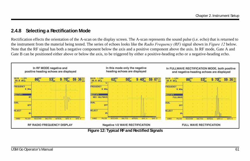
Chapter 2. Instrument Setup
2.4.8 Selecting a Rectification Mode
Rectification effects the orientation of the A-scan on the display screen. The A-scan represents the sound pulse (i.e. echo) that is returned to the instrument from the material being tested. The series of echoes looks like the Radio Frequency (RF) signal shown in Figure 12 below. Note that the RF signal has both a negative component below the axis and a positive component above the axis. In RF mode, Gate A and Gate B can be positioned either above or below the axis, to be triggered by either a positive-heading echo or a negative-heading echo.
Figure 12: Typical RF and Rectified Signals
USM Go Operator’s Manual 61

Chapter 2. Instrument Setup
2.4.8 Selecting a Rectification Mode (cont.)
• Positive Half Rectification means that only the upper (i.e. positive) half of the RF signal is displayed.
• Negative Half Rectification means that only the bottom (i.e. negative) half of the RF signal is displayed (see Figure 12 on page 61). Note that although only the negative half of the RF signal is displayed, it is shown in the same orientation as a positive component to simplify viewing.
• Full-Wave Rectification combines the positive- and negative-rectified signals together, and displays both of them in a positive orientation (see Figure 12 on page 61).
Use the procedure on the next page to select a rectification mode.
62 USM Go Operator’s Manual

Chapter 2. Instrument Setup
2.4.8 Selecting a Rectification Mode (cont.)
1. In the ACQUIRE menu, activate the RECEIVER submenu using the joystick ( ).
2. Use the joystick ( ) to select the function titled RECTIFY. The following options are available:
• NEG HALFWAVE - Shows the negative component of the RF signal but displays it in a positive orientation.
• POS HALFWAVE - Shows the positive component of the RF signal.
• FULLWAVE - Shows the positive and negative halves of the RF wave, but both are oriented in the positive direction.
• RF - Shows the echo with no rectification.
3. Press the function toggle or move the joystick ( ) to select the desired rectification method.
4. After completing your selection, move the joystick up or down ( ) to navigate away from this function.
USM Go Operator’s Manual 63

Chapter 2. Instrument Setup
2.4.9 Setting the A-Scan REJECT Level
A portion of the A-Scan can be omitted from the display screen, by defining the percentage of the full-screen height you wish to omit. To set a reject percentage:
1. In the ACQUIRE menu, activate the RECEIVER submenu using the joystick ( ).
2. Use the joystick ( ) to select the function titled REJECT.
3. To change the amount of the A-Scan you wish to omit from the display, as a percentage of the full-screen height, either move the
joystick ( ) or press the function toggle. You may omit a portion of the A-Scan up to 80% of the full-screen height.
Note: Whenever REJECT is set to a value greater then 0%, the reject icon (see Figure 6 on page 19) is displayed in the status bar.
64 USM Go Operator’s Manual
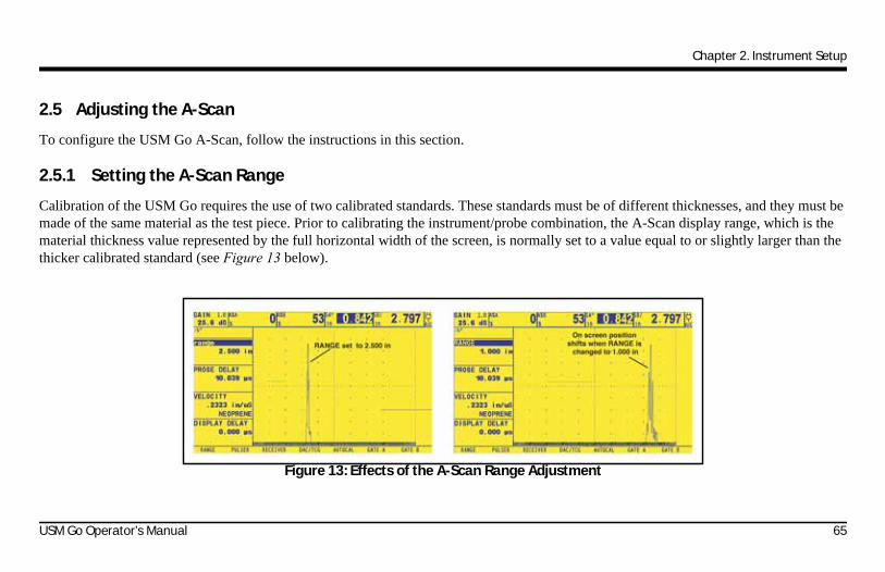
Chapter 2. Instrument Setup
2.5 Adjusting the A-Scan
To configure the USM Go A-Scan, follow the instructions in this section.
2.5.1 Setting the A-Scan Range
Calibration of the USM Go requires the use of two calibrated standards. These standards must be of different thicknesses, and they must be made of the same material as the test piece. Prior to calibrating the instrument/probe combination, the A-Scan display range, which is the material thickness value represented by the full horizontal width of the screen, is normally set to a value equal to or slightly larger than the thicker calibrated standard (see Figure 13 below).
Figure 13: Effects of the A-Scan Range Adjustment
USM Go Operator’s Manual 65

Chapter 2. Instrument Setup
2.5.1 Setting the A-Scan Range (cont.)
To set the A-Scan range:
1. In the ACQUIRE menu, activate the RANGE submenu using the joystick ( ).
2. Use the joystick ( ) to select the function titled RANGE, which has both coarse and fine adjustment modes. Coarse adjustments are made with the function toggle, while fine adjustments are made with the joystick. When “RANGE” appears in all capital letters, coarse adjustments are being made, while fine adjustments occur when “range” appears in all lower-case letters.
3. Press the function toggle or move the joystick ( ) to change the range setting. Values from 0.040 to 1100 in. are allowed.
Note: Pressing both buttons on the Function Toggle simultaneously resets the RANGE to the default value of 10.000 in.
4. After completing your selection, move the joystick up or down ( ) to navigate away from this function.
66 USM Go Operator’s Manual

Chapter 2. Instrument Setup
2.5.2 Setting the Display Delay
The display delay function shifts the displayed A-Scan to the left or the right in the viewing window. To set the display delay:
1. In the ACQUIRE menu, activate the RANGE submenu using the joystick ( ).
2. Use the joystick ( ) to select the function titled DISPLAY DELAY.
3. Press the function toggle or move the joystick ( ) to change the display delay. As you change the value, you should see the displayed echoes shift to the left or the right.
Note: Pressing both buttons on the Function Toggle simultaneously resets the DELAY to the default value of 0.
4. After completing your selection, move the joystick up or down ( ) to navigate away from this function.
USM Go Operator’s Manual 67

Chapter 2. Instrument Setup
2.6 Calibrating the Instrument
To calibrate the USM Go, follow the instructions in this section.
2.6.1 Pre-Calibration Check List
To improve the accuracy and quality of your calibration, be sure that the following steps have been taken before beginning the calibration:
• Install the probe
• Adjust the DUAL (RECEIVER) setting to match probe
• Set the material type
• Set the DISPLAY DELAY to 0 (recommended)
• Set the PRF to AUTO LOW
• Set TCG to OFF
• Set REJECT to 0 (recommended).
68 USM Go Operator’s Manual

Chapter 2. Instrument Setup
2.6.2 Using AUTOCAL
Note: While following the instructions in this section, refer to Figure 14 on page 70.
1. In the ACQUIRE menu, activate the AUTOCAL submenu using the joystick ( ).
2. Use the joystick ( ) to select the function titled S-REF1. Then, press the function toggle or move the joystick ( ) to change the value to match the thickness of the thinner calibration standard. The S-REF1 function has both coarse and fine adjustment modes. Coarse adjustments are made with the function toggle, while fine adjustments are made with the joystick.
3. Use the joystick ( ) to select the function titled S-REF2. Then, press the function toggle or move the joystick ( ) to change the value to match the thickness of the thicker calibration standard. The S-REF2 function has both coarse and fine adjustment modes. Coarse adjustments are made with the function toggle, while fine adjustments are made with the joystick.
4. Apply couplant and couple the probe to the thinner calibration standard. With the A START function highlighted, press the function
toggle or move the joystick ( ) to shift the starting point of Gate A until Gate A lies over the echo corresponding to the thickness of the thinner standard (see Figure 14 on page 70). Coarse adjustments are made with the function toggle, while fine adjustments are made with the joystick.
USM Go Operator’s Manual 69

Chapter 2. Instrument Setup
2.6.2 Using AUTOCAL (cont.)
Figure 14: Auto Calibration Procedures
70 USM Go Operator’s Manual

Chapter 2. Instrument Setup
2.6.2 Using AUTOCAL (cont.)
Note: During the following steps, pressing both buttons on the Gain Toggle simultaneously activates the AUTO80 function.
5. Use the joystick ( ) to select the function titled RECORD. The value in the function box changes from “OFF” to “S-REF1?”.
While maintaining the signal in Gate A, move the joystick right or left ( ) to record the reference echo. The value in the function box now reads “S-REF2?”.
6. Apply couplant and couple the probe to the thicker calibration standard. Then, use the joystick ( ) to select the function titled
A START. Press the function toggle or move the joystick ( ) to shift the starting point of Gate A until Gate A lies over the echo corresponding to the thickness of the thicker standard (see Figure 14 on page 70). Coarse adjustments are made with the function toggle, while fine adjustments are made with the joystick.
7. Use the joystick ( ) to select the function titled RECORD. While maintaining the signal in Gate A, move the joystick right or
left ( ) to record the reference echo. The value in the function box now reads “OFF”.
USM Go Operator’s Manual 71

Chapter 2. Instrument Setup
2.6.3 Checking the Calibration Results
Following the calibration procedure, the calculated acoustical velocity and probe delay are displayed. To view these calculated values:
1. In the ACQUIRE menu, activate the RANGE submenu using the joystick ( ).
2. Press the function toggle or move the joystick ( ) to view the following selections:
• PROBE DELAY - The adjustment made as a result of the AUTOCAL (zeroing) procedure is shown. This represents the time delay caused by sound-wave traveling through the probe membrane, wear plate, or delay line.
• VELOCITY - The calculated velocity after the calibration is shown. The material type is listed as “custom”.
72 USM Go Operator’s Manual

Chapter 2. Instrument Setup
2.7 Using the Calibration Reminder Alarm
The USM Go incorporates a timed alarm feature that causes an icon to appear on user-defined input intervals between 0.5 and 4.0 hours. To use this alarm:
1. In the SETUP menu, activate the CONFIG2 submenu using the joystick ( ).
2. Use the joystick ( ) to select the function titled CAL REMINDER, then press the center of the joystick ( ) to activate the function. Input the intervals at which the reminder alarm will trigger (between 0.5 and 4.0 hours). Setting this value automatically resets the alarm to trigger on the specified intervals. This function also allows the alarm to be disabled.
3. Press the function toggle or move the joystick ( ) to change the alarm interval.
4. Select and activate CAL RESET to acknowledge the triggered alarm and reset it to resume normal operation.
Note: The selection of the PROBE DELAY or VELOCITY functions also resets the alarm.
USM Go Operator’s Manual 73

Chapter 2. Instrument Setup
2.8 Activating Instrument Upgrades
When provided, activation codes matched to your USM Go serial number can be input via the CODE submenu, which is located in the CONFIG menu. This submenu also lists the serial number assigned to your instrument. To input an activation code:
1. In the SETUP menu, activate the CONFIG1 submenu using the joystick ( ).
2. Use the joystick ( ) to select the function titled CODE, and then press the center of the joystick ( ) to activate the function. Note that the first character of the current code value is highlighted.
3. Use the joystick ( ) to change the highlighted character to match the value provided by GE. Then, move the joystick ( ) to select the next character, and continue modifying the values until they all match the code provided by GE.
Note: Holding either end of the Function Toggle down for three seconds resets all values in the code to 0.
74 USM Go Operator’s Manual
Chapter 2. Instrument Setup
2.8 Activating Instrument Upgrades (cont.)
4. After completing the code entry, press the center of the joystick ( ) to deactivate the function.
5. Use the joystick ( ) to select the function titled CONFIRM, and then press the center of the joystick ( ) to acknowledge that the new code is correct.
6. Be sure to follow on-screen instructions to successfully complete the activation.
USM Go Operator’s Manual 75

Chapter 2. Instrument Setup
[no content intended for this page - proceed to next page]
76 USM Go Operator’s Manual

Chapter 3. Making Measurements
Chapter 3. Making Measurements
This chapter explains how to configure the USM Go flaw detection and thickness measurement capabilities. It then explains how to make ultrasonic measurements.
3.1 Configuring Gate A and Gate B
Setting the position and the characteristics of Gate A and Gate B is the first step in configuring the instrument for flaw detection or material thickness measurements. The GATE A and GATE B submenus control the location of Gate A and Gate B, while the EVAL and CONFIG2 submenus in the SETUP menu control the operating characteristics for the gates.
3.1.1 Activating Automatic Gate Threshold (AGT)
When Automatic Gate Threshold (AGT) is activated, the corresponding gate's threshold is set automatically.
Note: An icon is displayed in the Symbol Area when the AGT mode is activated.
USM Go Operator’s Manual 77

Chapter 3. Making Measurements
3.1.1 Activating Automatic Gate Threshold (AGT) (cont.)
To configure the Automatic Gate Threshold (AGT) function, follow this procedure:
1. In the SETUP menu, activate the EVAL submenu using the joystick ( ), and then the EVALMODE option.
2. Use the joystick ( ) to select the function titled AGT. Then press the center of the joystick ( ) to activate the function.
3. Move the joystick to select the particular AGT mode:
• GATE A
• GATE B
• GATE A/GATE B
4. Press the center of the joystick ( ) to set the setting.
78 USM Go Operator’s Manual

Chapter 3. Making Measurements
3.1.2 Positioning the Gates
Use the procedures in this section to set the vertical and horizontal position of Gate A and Gate B. Remember that gate position has the following effects on instrument performance:
• A-Scan echoes on the right side of the display screen represent features that occur at a greater depth from the test-material surface than those on the left side of the display screen. Therefore, moving a gate to the right means that the gate is evaluating a deeper portion of the test material.
• A wider gate setting means that the gate is evaluating a thicker portion of the test material.
• Increasing the vertical height, called the threshold, of a gate means that only reflected signals of sufficiently large amplitude will cross the gate.
To configure the gate parameters, complete the following steps and then proceed to the appropriate section:
1. In the ACQUIRE menu, activate the Gate A or Gate B submenu using the joystick ( ).
2. Choose the desired function from the available options.
USM Go Operator’s Manual 79

Chapter 3. Making Measurements
3.1.2a Setting the Gate Starting Point (GATE A or GATE B-GATE START)
1. In the ACQUIRE menu, activate the GATE A or GATE B submenu using the joystick ( ).
2. Use the joystick ( ) to select the GATE A START (or GATE B START) function.
3. To change the gate starting point, either move the joystick ( ) or press the function toggle.
Increasing and decreasing the value of the starting point moves the gate to the right and left, respectively. The gate starting point remains as set here, even when width adjustments are made.
Note: The GATE A START and GATE B START functions have both coarse and fine adjustment modes. Coarse adjustments are made with the function toggle, while fine adjustments are made with the joystick. When the function name appears in all capital letters, coarse adjustments are being made, while fine adjustments occur when the function name appears in all lower-case letters.
4. After completing your selection, move the joystick up or down ( ) to navigate away from this function.
80 USM Go Operator’s Manual
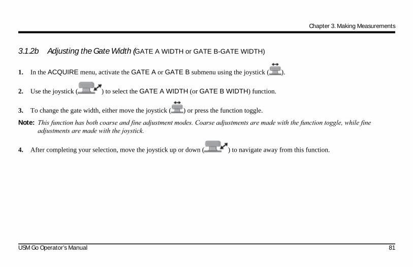
Chapter 3. Making Measurements
3.1.2b Adjusting the Gate Width (GATE A WIDTH or GATE B-GATE WIDTH)
1. In the ACQUIRE menu, activate the GATE A or GATE B submenu using the joystick ( ).
2. Use the joystick ( ) to select the GATE A WIDTH (or GATE B WIDTH) function.
3. To change the gate width, either move the joystick ( ) or press the function toggle.
Note: This function has both coarse and fine adjustment modes. Coarse adjustments are made with the function toggle, while fine adjustments are made with the joystick.
4. After completing your selection, move the joystick up or down ( ) to navigate away from this function.
USM Go Operator’s Manual 81

Chapter 3. Making Measurements
3.1.2c Setting the Gate Threshold (Vertical Position) (A THRESHOLD or B THRESHOLD)
1. In the ACQUIRE menu, activate the GATE A or GATE B submenu using the joystick ( ).
2. Use the joystick ( ) to select the A THRESHOLD (or B THRESHOLD) function.
IMPORTANT: If the AGT function has been activated (see “Activating Automatic Gate Threshold (AGT)” on page 77), the A THRESHOLD menu parameter is replaced with the AGT Scale Value. The scale value is displayed in the form of ±AGT = ss%, where ss represents the AGT scale value. The user can modify the AGT scale value using the joystick and/or the function keys.
3. To change the gate height, either move the joystick ( ) or press the function toggle. Increasing or decreasing the value of the threshold moves the gate up or down, respectively.
4. After completing your selection, move the joystick up or down ( ) to navigate away from this function.
82 USM Go Operator’s Manual

Chapter 3. Making Measurements
3.1.3 Selecting the TOF-Detection Method
A-Scan signals crossing either Gate A or Gate B are evaluated for the purposes of flaw detection and material thickness evaluation. When the signal crosses Gate A or Gate B, either the gate-crossing point (i.e. the flank) of the signal, or the maximum point (i.e. the peak) of the signal in that specific gate is used for evaluation purposes. The TOF MODE function allows the user to specify which A-Scan feature (FLANK or PEAK or JFLANK) is used to evaluate the signal in each gate.
1. In the ACQUIRE menu, activate the GATE A or GATE B submenu using the joystick ( ).
2. Use the joystick ( ) to select the TOF MODE function.
3. To change the gate detection mode, either move the joystick ( ) or press the function toggle. The following options are available:
• PEAK - All detection, whether time-based and peak height, is based on the HIGHEST triggering echo in the gate.
• FLANK - The time-based triggering point is the first flank to cross the gate, and amplitude-based results are based on the HIGHEST peak of any echo crossing the gate. This is not necessarily the peak of the same echo whose flank triggered the gate.
• JFLANK - The time-based triggering point is the first flank to cross the gate, and the amplitude-based results are based on the peak of this first echo to cross the gate. This is not necessarily the highest echo in the gate.
USM Go Operator’s Manual 83
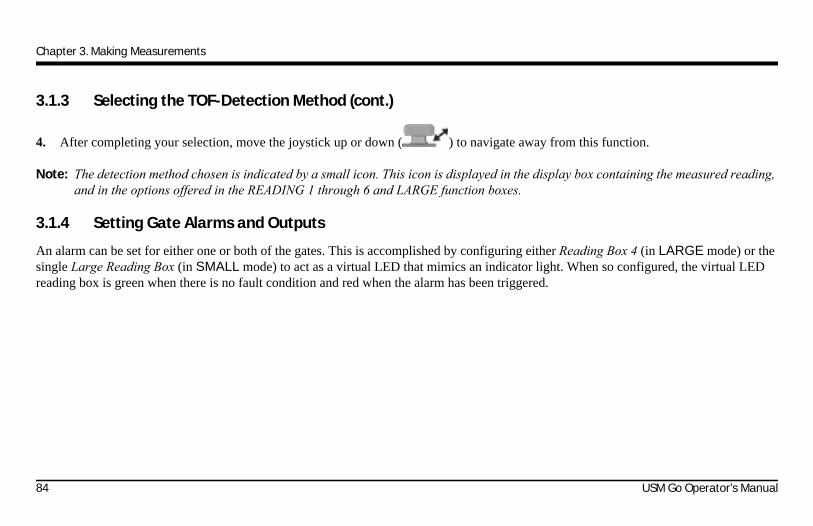
Chapter 3. Making Measurements
3.1.3 Selecting the TOF-Detection Method (cont.)
4. After completing your selection, move the joystick up or down ( ) to navigate away from this function.
Note: The detection method chosen is indicated by a small icon. This icon is displayed in the display box containing the measured reading, and in the options offered in the READING 1 through 6 and LARGE function boxes.
3.1.4 Setting Gate Alarms and Outputs
An alarm can be set for either one or both of the gates. This is accomplished by configuring either Reading Box 4 (in LARGE mode) or the single Large Reading Box (in SMALL mode) to act as a virtual LED that mimics an indicator light. When so configured, the virtual LED reading box is green when there is no fault condition and red when the alarm has been triggered.
84 USM Go Operator’s Manual

Chapter 3. Making Measurements
3.1.4a Defining Gate-Alarm Logic (SETUP-CONFIG2-GATE A or B LOGIC)
Each gate alarm can be triggered by one of two circumstances: either when an A-Scan echo crosses the gate or when no A-Scan echo crosses the gate. Use the following procedure to specify the gate LOGIC settings:
1. In the SETUP menu, activate the CONFIG2 submenu using the joystick ( ).
2. Use the joystick ( ) to select the function titled GATE A (or GATE B) LOGIC. Press the center of the joystick ( ) to activate the function.
3. To choose the gate-alarm triggering logic, move the joystick up or down ( ). The following options are available:
• POSITIVE - An A-Scan signal crosses the gate
• NEGATIVE - No A-Scan signal crosses the gate
• OFF - No alarm is connected to the selected gate
Note: Gate A and Gate B can be configured so that either gate triggers the alarm.
4. After making your choice, press the center of the joystick ( ) to deactivate the function.
USM Go Operator’s Manual 85

Chapter 3. Making Measurements
3.1.4b Assigning Alarm Output Indicator Lights (SETUP-CONFIG2-OUTPUT SELECT)
As an option, one reading box may be configured as a virtual LED (see “Setting Gate Alarms and Outputs” on page 84), which is green when there is no fault condition and red when the alarm has been triggered. This virtual LED corresponds to an OUTPUT, which is in-turn assigned to a gate alarm. When an alarm is triggered, the virtual LED is illuminated (except when the GATE LOGIC is set to OFF). Use the following procedure to indicate which gate activates the virtual LED:
1. In the SETUP menu, activate the CONFIG2 submenu using the joystick ( ).
2. Use the joystick ( ) to select the function titled OUTPUT SELECT. Press the center of the joystick ( ) to activate the function.
3. To configure the gate-alarm virtual LED operation, move the joystick up or down ( ). The following options are available:
• A(+), A(-) - the virtual LED indicates the Gate A alarm is triggered (see previous page for description of + and - alarms)
• B(+), B(-) - the virtual LED indicates the B Gate alarm is triggered (see previous page for description of + and - alarms)
• A or B(+), A or B (-) - the virtual LED indicates either Gate alarm is triggered (see previous page for description of + and - alarms)
4. After making your choice, press the center of the joystick ( ) to deactivate the function.
86 USM Go Operator’s Manual

Chapter 3. Making Measurements
3.1.4c Select Gate to Be Magnified When Function Toggle Is Pressed (SETUP-EVAL-MAGNIFY GATE)
The user can indicate the action to be taken when either end of the Function Toggle is pressed. One option magnifies the A-Scan display, so the assigned gate spans the entire displayed range. To specify the gate that should be magnified on demand:
1. In the SETUP menu, activate the EVAL submenu using the joystick ( ).
2. Use the joystick ( ) to select the function titled MAGNIFY GATE. Press the center of the joystick ( ) to activate the function.
3. To select Gate A or the Gate B, move the joystick up or down ( ).
Note: Pressing the assigned end of Function Toggle, when FUNCTION1 or FUNCTION 2 is set to MAGNIFY GATE, magnifies the display so the selected gate spans the entire displayed range.
4. After making your choice, press the center of the joystick ( ) to deactivate the function.
USM Go Operator’s Manual 87
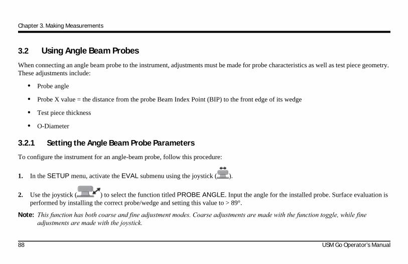
Chapter 3. Making Measurements
3.2 Using Angle Beam Probes
When connecting an angle beam probe to the instrument, adjustments must be made for probe characteristics as well as test piece geometry. These adjustments include:
• Probe angle
• Probe X value = the distance from the probe Beam Index Point (BIP) to the front edge of its wedge
• Test piece thickness
• O-Diameter
3.2.1 Setting the Angle Beam Probe Parameters
To configure the instrument for an angle-beam probe, follow this procedure:
1. In the SETUP menu, activate the EVAL submenu using the joystick ( ).
2. Use the joystick ( ) to select the function titled PROBE ANGLE. Input the angle for the installed probe. Surface evaluation is performed by installing the correct probe/wedge and setting this value to > 89°.
Note: This function has both coarse and fine adjustment modes. Coarse adjustments are made with the function toggle, while fine adjustments are made with the joystick.
88 USM Go Operator’s Manual

Chapter 3. Making Measurements
3.2.1 Setting the Angle Beam Probe Parameters (cont.)
3. Use the joystick ( ) to select the THICKNESS function, and input the thickness of the test piece. The thickness of a solid rod should be input as 1/2 of its diameter.
4. Use the joystick ( ) to select the X VALUE function, and input the user-determined X value for the probe. This compensates for the distance from the BIP to the front of the probe wedge.
5. Use the joystick ( ) to select the O DIAMETER function, and input the outside diameter (from 50 to 2000 mm) of a curved test piece. When set to FLAT, curvature correction is not applied.
Note: Based on the values input for the PROBE ANGLE, THICKNESS, X VALUE, and O DIAMETER parameters, the instrument operates in one of five modes. Each of these modes is represented by an icon in the icon area at the upper left corner of the screen. See Figure 6 on page 19 for an illustration of these icons.
USM Go Operator’s Manual 89

Chapter 3. Making Measurements
3.2.2 Indicating Leg with Color
The leg in which a reflector is encountered, can be visually indicated on the instrument display using color. Setting the COLOR LEG function, located in the EVAL submenu of the SETUP menu, to ON causes each ultrasonic time region to be displayed in a unique color.
3.3 Displaying Measured Results
The instrument is capable of displaying up to seven measured readings at one time. The displayed readings are selected using the EVAL submenu located in the SETUP menu. The parameters available for display, which depends on the instrument configuration and the evaluation mode, include the following:
• A%A - Amplitude, as a % of full-screen height, of the highest echo falling within the width of Gate A
• A%B - Amplitude, as a % of full-screen height, of the highest echo falling within the width of Gate B
Note: When S, D, P, or R readings are displayed, the Gate-Detection Mode setting for the referenced gate (A or B) is indicated by a^ for Peak Mode or a / for Flank Mode.
• SA - Sound-Path distance or duration, represented by the highest echo or the first flank to cross Gate A
• SB - Sound-Path distance or duration, represented by the highest echo or the first flank to cross Gate B
• SBA - Sound-Path distance or duration, from the highest echo or the first flank in Gate A to the echo in Gate B. The reading is only available if Gate A and Gate B are set to ON.
90 USM Go Operator’s Manual
Chapter 3. Making Measurements
3.3 Displaying Measured Results (cont.)
• DA - Material-thickness depth from the probe-contacted side of the test-piece surface to the reflector, represented by the Gate A echo.
• DB - Material-thickness depth from the probe-contacted side of the test-piece surface to the reflector, represented by the Gate B echo.
• LA - Leg number of the reflector, represented by the Gate A echo.
• LB - Leg number of the reflector, represented by the Gate B echo.
• PA - Projection distance from the probe BIP to the reflector, represented by the Gate A echo.
• PB - Projection distance from the probe BIP to the reflector, represented by the Gate B echo.
• RA - Projection distance from the probe BIP to the reflector, represented by the Gate A echo, minus the current X-VALUE.
• RB - Projection distance from the probe BIP to the reflector, represented by the Gate B echo, minus the current X-VALUE.
• A%rA - Amplitude of the signal crossing Gate A, as a percentage of the active EVAL MODE reference amplitude.
• A%rB - Amplitude of the signal crossing Gate B, as a percentage of the active EVAL MODE reference amplitude.
• dBrA - dB equivalent height difference between the signal crossing Gate A and the active EVAL MODE reference height.
• dBrB - dB equivalent height difference between the signal crossing Gate B and the active EVAL MODE reference height.
USM Go Operator’s Manual 91

Chapter 3. Making Measurements
3.3 Displaying Measured Results (cont.)Note: Reference results (identified with “r”) behavior based on EVAL MODE are as follows:
• DAC - % Amplitude or dB compared to corresponding DAC curve point
• TCG - % Amplitude or dB compared to TCG reference level
• dB REF - % Amplitude or dB compared to reference level
• DGS - % Amplitude or dB compared to curve/size selected
• JISDAC - % Amplitude or dB compared to JIS LINE (H, M, or L) set to BOLD
• NONE - % Amplitude or dB compared to gate threshold height
• CLS - JIS CLASS (I, II, III, or IV). Available only when JISDAC evaluation mode is active.
• ERS - Evaluates the reflected echo in DGS Mode, and calculates the Equivalent Reflector Size
• GT - DGS test gain, which initializes the DGS curve maximum height at 80% FSH.
• GR - DGS reference gain, which represents the instrument gain at which the reference echo peak reaches 80% FSH.
• VIRTUAL LED - Reading box color changes from green to red when a gate alarm is triggered.
92 USM Go Operator’s Manual
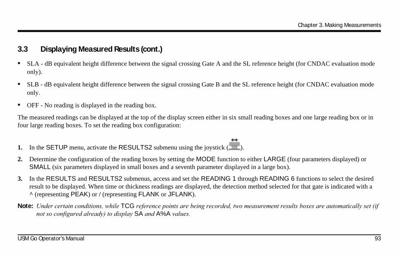
Chapter 3. Making Measurements
3.3 Displaying Measured Results (cont.)
• SLA - dB equivalent height difference between the signal crossing Gate A and the SL reference height (for CNDAC evaluation mode only).
• SLB - dB equivalent height difference between the signal crossing Gate B and the SL reference height (for CNDAC evaluation mode only.
• OFF - No reading is displayed in the reading box.
The measured readings can be displayed at the top of the display screen either in six small reading boxes and one large reading box or in four large reading boxes. To set the reading box configuration:
1. In the SETUP menu, activate the RESULTS2 submenu using the joystick ( ).
2. Determine the configuration of the reading boxes by setting the MODE function to either LARGE (four parameters displayed) or SMALL (six parameters displayed in small boxes and a seventh parameter displayed in a large box).
3. In the RESULTS and RESULTS2 submenus, access and set the READING 1 through READING 6 functions to select the desired result to be displayed. When time or thickness readings are displayed, the detection method selected for that gate is indicated with a^ (representing PEAK) or / (representing FLANK or JFLANK).
Note: Under certain conditions, while TCG reference points are being recorded, two measurement results boxes are automatically set (if not so configured already) to display SA and A%A values.
USM Go Operator’s Manual 93

Chapter 3. Making Measurements
3.4 Locking the Gain Toggle and the Joystick
The gain toggle can be locked so that pressing it has no effect on the instrument.
1. In the SETUP menu, activate the CONFIG2 submenu using the joystick ( ).
2. Use the joystick ( ) to select the function titled dB STEP. Press the center of the joystick ( ) to activate the function.
3. Move the joystick left or right ( ) to change the value of dB STEP until the word LOCK appears as the dB STEP value. The gain toggle is now locked.
4. To unlock the gain toggle, change the setting of dB STEP to any value other than LOCK.
5. After making your choice, press the center of the joystick ( ) to deactivate the function.
Joystick operation is disabled by assigning either FUNCTION1 or FUNCTION2 to a value of JOYSTICK LOCK, then pressing that end of the Function Toggle. When the joystick is locked, the Lock icon (see Figure 6 on page 19) appears on the display. To unlock the joystick, simply press the assigned end of the Function Toggle a second time.
IMPORTANT: When the joystick is locked, the center-press function still works.
94 USM Go Operator’s Manual
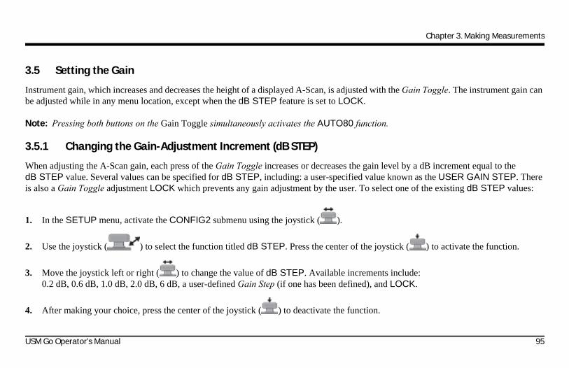
Chapter 3. Making Measurements
3.5 Setting the Gain
Instrument gain, which increases and decreases the height of a displayed A-Scan, is adjusted with the Gain Toggle. The instrument gain can be adjusted while in any menu location, except when the dB STEP feature is set to LOCK.
Note: Pressing both buttons on the Gain Toggle simultaneously activates the AUTO80 function.
3.5.1 Changing the Gain-Adjustment Increment (dB STEP)
When adjusting the A-Scan gain, each press of the Gain Toggle increases or decreases the gain level by a dB increment equal to the dB STEP value. Several values can be specified for dB STEP, including: a user-specified value known as the USER GAIN STEP. There is also a Gain Toggle adjustment LOCK which prevents any gain adjustment by the user. To select one of the existing dB STEP values:
1. In the SETUP menu, activate the CONFIG2 submenu using the joystick ( ).
2. Use the joystick ( ) to select the function titled dB STEP. Press the center of the joystick ( ) to activate the function.
3. Move the joystick left or right ( ) to change the value of dB STEP. Available increments include:0.2 dB, 0.6 dB, 1.0 dB, 2.0 dB, 6 dB, a user-defined Gain Step (if one has been defined), and LOCK.
4. After making your choice, press the center of the joystick ( ) to deactivate the function.
USM Go Operator’s Manual 95

Chapter 3. Making Measurements
3.5.2 Setting the User-Defined Gain Step (SETUP-GAIN-USER GAIN STEP)
When adjusting the A-Scan gain, each press of the Gain Toggle increases or decreases the gain level by the amount of the dB STEP. To enter a user-specified gain step, known as USER GAIN STEP, complete the following steps:
1. In the SETUP menu, activate the CONFIG2 submenu using the joystick ( ).
2. Use the joystick ( ) to select the function titled USER GAIN STEP. Press the center of the joystick ( ) to activate the function.
3. Move the joystick left or right ( ) to change the value of USER GAIN STEP. This value is now available as an option whenever the dB STEP function is activated.
4. After making your choice, press the center of the joystick ( ) to deactivate the function.
96 USM Go Operator’s Manual
Chapter 3. Making Measurements
3.6 Auto Gain Control
The Auto Gain Control option enables the operator to set the minimum and maximum amplitude for the echo which passes through Gate A. When the echo's amplitude is lower than the minimum value or higher than the maximum value, the gain will be adjusted automatically to make the echo's amplitude at the middle of the minimum value and maximum value. To enable auto gain control:
1. In the CONFIG4 menu, select the Auto Gain Ctrl submenu.
2. Set the CTRL MODE setting as ON.
3. Press the center of the joystick ( ) to save the setting.
3.6.1 Setting Maximum Amplitude
1. In the CONFIG4 menu, select the Auto Gain Ctrl submenu
2. Move the joystick to select the MAX AMP.% function, and press the center of joystick ( ) to activate the function.
3. Move the joystick left/right ( ) to set the value.
4. Press the center of the joystick ( ) to deactivate the function and save the setting.
USM Go Operator’s Manual 97

Chapter 3. Making Measurements
3.6.2 Setting Minimum Amplitude
1. In the CONFIG4 menu, select the Auto Gain Ctrl submenu.
2. Move the joystick to select the MIN AMP.% function, and press the center of the joystick ( ) to activate the function.
3. Move the joystick left/right ( ) to set the value.
4. Press the center of the joystick ( ) to deactivate the function and save the setting.
3.6.3 Setting Noise Level
When the echo's amplitude is lower than the noise level, it will be ignored as a noise.
1. In the CONFIG4 menu, select the Auto Gain Ctrl submenu.
2. Move the joystick to select the NOISE LEVEL.% function, and press the center of the joystick ( ) to activate the function.
3. Move the joystick left/right ( ) to set the value.
4. Press the center of the joystick ( ) to deactivate the function and save the setting.Note: The maximum amplitude must be higher than the minimum amplitude, and the minimum amplitude must be higher than the noise
level.
98 USM Go Operator’s Manual

Chapter 3. Making Measurements
3.7 Freezing the A-Scan Display
By using the FUNCTION1 or FUNCTION2 functions in the SETUP menu, you can program one end of the Function Toggle to FREEZE the display. Then, whenever an A-Scan is active, pressing that end of the Function Toggle freezes the A-Scan display. The active A-Scan will remain as it appeared when the toggle was pressed and the display will remain frozen until it is pressed again. While the display is frozen, the displayed readings are based on the frozen echoes.
Once in frozen mode, the user can change the settings of Gate A and Gate B to obtain the new measured results. While the display is frozen, the settings of Gate A and Gate B still can be changed. The measured results are updated when the settings are changed.
Note: When the acquisition time is longer than twice the quotient of range and velocity, the precision of measured results will be reduced.
USM Go Operator’s Manual 99

Chapter 3. Making Measurements
3.8 Freeze on A-Scan Operation
When this feature is enabled, if an echo passes through the gate, the A-Scan curve will be frozen automatically.
1. In the CONFIG3 menu, activate the FREEZE submenu.
2. Move the joystick to select FREEZE MODE function, and then press the center of joystick( ) to activate the function.
3. Move the joystick left/right ( ) to select the option.
• STANDARD - Normal setting. Pressing the function key to freeze the A-Scan display.
• AFREEZE - If an echo passes through Gate A, A-Scan display will be frozen automatically.
• BFREEZE - If an echo passes through Gate B, A-Scan display will be frozen automatically.
• AB-FREEZE - If an echo passes through Gate A or Gate B, A-Scan display will be frozen automatically.
• COMPARE - A-Scan comparison. The current A-Scan display can be compared with an A-Scan curve stored before or a frozen A-Scan curve.
4. Press the center of the joystick ( ) to deactivate the function and save the setting.
100 USM Go Operator’s Manual
Chapter 3. Making Measurements
3.9 Echo Envelope
1. In the CONFIG3 menu, activate the FREEZE submenu.
2. Use the joystick to select the ENVELOPE function, and then press the center of the joystick ( ) to activate the function.
3. Move the joystick left/right ( ) to turn on/off the ENVELOPE option.
4. Press the center of the joystick ( ) again to deactivate the function and save the setting.
3.9.1 Envelope Color
1. In the CONFIG3 menu, activate the FREEZE submenu.
2. Use the joystick to select the ENVELOPE COLOR parameter, and then press the center of joystick ( ) to activate the function.
3. Move the joystick left/right ( ) to select the color for ENVELOPE curve.
4. Press the center of the joystick ( ) again to deactivate the function and save the setting.
USM Go Operator’s Manual 101

Chapter 3. Making Measurements
3.10 Comparison Mode
When the Comparison mode is turned ON, an A-Scan curve from a dataset file or a frozen A-Scan is displayed on the screen as a reference curve. If the envelope mode is ON, the envelope curve is displayed as a reference curve.
To enable the Comparison mode:
1. In the CONFIG3 menu, select the FREEZE submenu.
2. Activate the FREEZE MODE function, and select the option, COMPARE.
3. Press the center of the joystick ( ) to deactivate the function and save the setting.
102 USM Go Operator’s Manual

Chapter 3. Making Measurements
3.11 DAC/TCG Evaluation Mode (Optional)
Note: Optional evaluation features, such as DAC/TCG, are selected via the EVAL MODE function in the EVAL menu. The functions for the selected evaluation mode then appears in the ACQUIRE menu.
Conventional measurements can be made using the Time Corrected Gain (TCG) and Distance Amplitude Correction (DAC) modes. The functions for these modes are accessed through the DAC/TCG menu on the ACQUIRE menu bar. The DAC and TCG modes operate based on a set of user-recorded data points. These points are recorded from the DAC/TCG menu as described below.
The TCG mode displays reflectors of equal size at equal A-Scan amplitudes, regardless of the depth of the reflector in the test material. This is accomplished by adjusting the gain at different locations in the A-scan display, corresponding to different material depths, to compensate for signal loss (or variation) due to attenuation, beam spread, or other factors.
The DAC mode displays all echoes at their true amplitude, without depth compensation. However, when operating in DAC mode, a Distance Amplitude Correction curve is superimposed on the A-Scan display. The curve represents the constant reflector size at varying material depth.
USM Go Operator’s Manual 103

Chapter 3. Making Measurements
3.12 Using DAC Mode (Optional)
When displayed, the DAC curve visually represents a line of constant reflector peaks over a range of material depths. Remember that in DAC mode, the only deviation from traditional display and operation is the appearance of the DAC curve. All A-Scan echoes are displayed at their non-compensated height. A DAC curve can be based on up to 16 data points (material depths).
A DAC curve is programmed using a series of same-reflector echoes at various depths, covering the range of depths to be inspected in the test material. Because near field and beam spread vary according to transducer size and frequency, and materials vary in attenuation and velocity, DAC must be programmed differently for different applications.
The minimum time difference between successive points is 60 ns. This corresponds to a distance of 0.18 mm (0.007 in.) at a velocity of 5900 m/s (.2323 in./s). Successive data points do not have to progressively decrease in amplitude. That is, the DAC/TCG curve does not have to have a constantly descending slope.
104 USM Go Operator’s Manual

Chapter 3. Making Measurements
3.12.1 Recording the DAC Curve
DAC Curve points are typically recorded from a standard with equally-sized reflectors (holes) located at various material depths. The primary echo from each of these points, for a total of up to 16 echoes, are recorded. When DAC mode is active, the instrument displays a line that represents echo peaks for constant reflectors at varying material depth. This line is drawn as either a curved, linear in gain, line based on a series of collected DAC points or a series of straight line segments that join these DAC points. Only one DAC curve can be stored at a time. To program the DAC curve proceed as follows:
1. In the ACQUIRE menu, activate the DAC/TCG submenu using the joystick ( ).
2. Couple the probe to the first reference point and use the GATE A START function to adjust Gate A so that it is broken by the primary echo. If necessary, use the Gain Toggle to adjust the gain so that the echo crosses Gate A, and the highest peak in Gate A is at approximately 80% of full-screen height. The highest peak must not be higher than 100% full-screen height.
Note: The AUTO 80 function allows for automatic application of gain to set the Gate A triggering echo to 80% of full screen height.
3. While Gate A is lined up over the first reference echo, use the joystick ( ) to select the function titled RECORD. Press the
center of the joystick ( ) to activate the function. When the value of the RECORD function changes from 0 to 1, you have recorded the first DAC Curve point, which is then treated as the reference echo. The amplitude value at which this point is recorded becomes the “reference amplitude” value. However, the “reference amplitude” is updated if a new point is recorded with an earlier TOF.
USM Go Operator’s Manual 105

Chapter 3. Making Measurements
3.12.1 Recording the DAC Curve (cont.)
Note: If the Gate Detection Mode is set to PEAK, after the first DAC reference point is stored, two measurement result boxes are automatically set, if not already configured, to display SA and A%A values.
4. Repeat steps 2 and 3 to record additional DAC Curve points, up to a maximum of 16 points. A minimum of two DAC Curve points are required to define the curve.
5. After entering all of your points, press the center of the joystick ( ) to deactivate the function. The TCG/DAC data is stored, using the amplitude of the earliest TOF as the reference amplitude.
6. In the SETUP menu, activate the DAC TYPE function using the joystick ( ). Then, select one of the following options:
• STRAIGHT: The DAC curve is displayed as a series of straight line segments that join the stored DAC points.
• CURVED: The DAC curve is displayed as a curved line that is linear in gain, based on the stored DAC points.
Note: DAC curve points and status are stored with a data set. When recalled, the curve status is the same as when it was stored.
106 USM Go Operator’s Manual

Chapter 3. Making Measurements
3.12.1 Working with DAC Mode
In DAC mode the instrument uses the user-input reference points to create a curve representing the amplitudes of echoes representing same-size reflectors at varying material depth. The recorded point data is stored until replaced or edited. To create a DAC curve and operate in DAC mode:
1. With the DAC/TCG menu accessed, select the SETUP submenu.
2. Use the TCG/DAC MODE menu to activate the DAC function. The DAC Curve appears whenever operating in DAC mode.
3. The DAC curve can appear either as a series of straight line segments joining the stored DAC points or as a curved (linear in gain) line based on these points. Access the DAC TYPE function in the SETUP submenu to display the desired DAC curve type.
Note: To operate in TCG/DAC mode, a DAC curve must first be generated. After the DAC curve has been generated, the TCG mode can be accessed by setting the TCG/DAC function value to TCG.
Note: When rectification is set to RF, reference lines are not displayed.
USM Go Operator’s Manual 107

Chapter 3. Making Measurements
3.13 Using TCG Mode (Optional)
When the optional TCG mode is in use, echoes from equally sized reflectors are shown at the same height on the A-Scan display. Before using the TCG mode do the following:
1. Make sure that the instrument/probe combination has been properly calibrated and that all instrument settings (PULSER,RECEIVER, etc.) have been properly configured. Changing these settings after the TCG reference points have been entered will affect the accuracy of your measurements.
2. Up to 16 TCG points may be recorded, but a minimum of two points are required to define the curve. This process allows the instrument to calculate and compensate for the effect of material depth on reflector echo height. Successive data points do not have to progressively decrease in amplitude. That is, the DAC/TCG curve does not have to have a constantly descending slope.
3.13.1 Generating the TCG Reference Curve
TCG reference points are derived from the points used to create the DAC curve. Points are typically taken from a standard with equally sized reflectors (holes) located at various material depths. The primary echo from each of these points, for a total of up to 16 echoes, are recorded. When TCG is active, the instrument compensates for different material thickness by applying a varying gain level to echoes at material depths other than the baseline depth.
Note: TCG reference points, curve, and status are stored with a data set. When recalled, curve status is the same as when it was stored.
108 USM Go Operator’s Manual
Chapter 3. Making Measurements
3.13.2 Working with TCG
In TCG mode the instrument uses the recorded reference points to calculate an amount of gain correction required to display each echo from same-size reflectors at the same amplitude. The recorded reference point data is stored until replaced or edited. To use the stored reference points and operate in TCG mode:
1. Enter the SETUP menu, and then select the TCG/DAC MODE function.
2. Activate the TCG/DAC MODE function, and select the TCG option.
3. Select the TCG DISPLAY function, and turn this feature ON or OFF.
Note: The TCG curve begins at the first reference point recorded. It then proceeds horizontally from the amplitude of this first reference point to the depth (i.e. time position) of the last reference point recorded.
Note: When rectification is set to RF, reference lines are not displayed.
USM Go Operator’s Manual 109

Chapter 3. Making Measurements
3.14 Adjusting DAC or TCG Display and Adding Offsets
After the DAC or TCG curves are displayed, the addition of guidelines offset from the reference line by a fixed or variable dB value provides enhanced evaluating capabilities. Similarly, the TRANSFER CORR function applies dB compensation for the difference in coupling conditions between the known standard and the test piece.
3.14.1 Defining DAC or TCG Curve Offsets (DAC/TCG-OFFSETS-MODE)
To add a series of guidelines, offset from the DAC or TCG curve by a definable dB increment (but not exceeding ± 24 dB from the reference curve):
1. Access the OFFSETS submenu in the DAC/TCG menu.
2. Set the MODE function to FIXED for evenly spaced offset lines or to CUSTOM for user-controlled offset line placement. Set this function to OFF to remove offset lines from the display.
3. If FIXED offset MODE is selected, set the OFFSET function to the dB increment at which offset lines are drawn above and below the DAC or TCG line.
4. If CUSTOM offset MODE is selected, access the OFFFSETS2 submenu and input the positive or negative offset at which each of up to four guidelines are drawn.
110 USM Go Operator’s Manual

Chapter 3. Making Measurements
3.14.2 Setting Transfer Correction (DAC/TCG-MAT ATTN-TRANSFER CORR)
To adjust the dB compensation for differences in ultrasonic coupling between the standard and the test piece:
1. Access the MAT ATTN submenu in the DAC/TCG menu.
2. Adjust the TRANSFER CORR function as required to compensate for coupling differences.
Note: When TRANSFER CORR is set to any value other than 0, the displayed gain value appears in a contrasting color, indicating that the amount of applied gain differs from the listed “instrument” gain.
USM Go Operator’s Manual 111

Chapter 3. Making Measurements
3.15 Editing and Deleting DAC and TCG Reference Points
After your reference points are recorded, they may be individually deleted, their values may be manually adjusted, or new points may be manually entered (as long as the total number does not exceed 16 points). To edit points or input additional points:
1. With the DAC/TCG menu accessed, select the EDIT submenu.
2. Activate the POINT function and select the desired point number (or NEW if adding a new point).
3. Activate the POINT POS. function and adjust (or input for NEW points) the horizontal position of the point.
4. Activate the POINT GAIN function to adjust (or input for NEW points) the applied gain (i.e. the vertical position) of the point. Note that this adjustment applies regardless of whether the point is used for TCG reference or a DAC curve.
5. Activate the ENTER function to confirm the adjusted point values (or the position of a new point). The DAC curve or the TCG reference function is adjusted to match the edited input.
6. To delete any single DAC point, press and hold the center of the joystick for the POINT, POINT POS, or POINT GAIN function while the point to be deleted is active. When prompted, confirm the deletion. Note that the first point cannot be deleted, and that all DAC curves must contain at least two points. Therefore, if a curve has only two points stored, neither can be deleted.
112 USM Go Operator’s Manual

Chapter 3. Making Measurements
3.16 Deleting a DAC Curve or TCG Reference Points
To delete a stored DAC curve or stored TCG reference points:
1. With the DAC/TCG menu activated, select the SETUP submenu.
2. Activate the DELETE CURVE function.
3. Activate the DELETE CURVE function a second time, then confirm your selection.
4. The statement in the function box changes to TCG/DAC MODE OFF.
3.17 DGS Evaluation Mode
Note: Evaluation features, such as DGS mode, are first selected by the user via the EVAL MODE function in the EVAL menu. The menu for the selected evaluation mode is then available in the ACQUIRE menu bar.
The USM Go Distance Gain Sizing (DGS) feature is accessed through the DGS menu, which is located in the ACQUIRE menu bar. DGS mode allows the user to use a particular probe to compare a reflector in a test piece with a known standard reflector. The DGS mode relies on a reference curve based on a recorded reference point. The procedure for recording a reference point using the DGS Menu is described on the next page.
USM Go Operator’s Manual 113
Chapter 3. Making Measurements
3.17 DGS Evaluation Mode (cont.)
Using the DGS mode (Distance Gain Size), you can compare the reflecting power of a natural flaw in the test object with that of a theoretical flaw (e.g. a circular, disk-shaped equivalent reflector) at the same depth.
CAUTION! You are comparing the reflecting power of a natural flaw with that of a theoretical flaw. No definitive conclusions may be drawn about the natural flaw (roughness, inclined position, etc.).
The DGS diagram forms the basis for this comparison of the reflecting power. This diagram consists of a set of curves showing the connection of three influencing variables:
• Distance (D) between the probe and circular, disk-shaped equivalent reflector
• Difference in gain (G) between various large circular, disk-shaped equivalent reflectors and an infinitely large backwall
• Size (S) of the circular, disk-shaped equivalent reflector. The influencing variable S remains constant for one curve in a set
The advantage of the DGS method lies in the fact that you can carry out reproducible evaluations of small discontinuities. This reproducibility is most important whenever you carry out an acceptance test.
114 USM Go Operator’s Manual

Chapter 3. Making Measurements
3.17 DGS Evaluation Mode (cont.)
In addition to the influencing variables already mentioned, these other factors affect the curve shape:
• sound attenuation
• transfer losses
• amplitude correction value
• probe
Also, the following probe parameters affect the curve shape:
• element or crystal diameter
• frequency
• delay length
• delay velocity
You can adjust these parameters in such a way that you can use the DGS method with many different probes and on various materials.
USM Go Operator’s Manual 115

Chapter 3. Making Measurements
3.17 DGS Evaluation Mode (cont.)
When the DGS mode is in use, echoes from equally-sized reflectors located at varying depths appear to lie along the DGS Reference Curve. When operating in DGS mode, the DGS Reference Curve is shown on the display screen. Before using the DGS mode, do the following:
• Calibrate the instrument/probe combination
• Make all required instrument settings related to the pulser, receiver, and material velocity functions
The instrument prevents changes to certain settings after the DGS Reference Echo has been recorded and DGS is turned ON.
3.17.1 Specifying a Probe and Preparing to Record the Reference Echo
Before using the DGS mode to evaluate reflectors in test pieces, the characteristics of the attached probe must be specified, certain characteristics of the reference standard must be input, and a reference echo must be stored. To specify the probe characteristics:
1. Select the DGS menu on the ACQUIRE menu bar.
2. Select the SETUP submenu, then the PROBE # function. Once activated, this function allows you to choose from a list of available probe types . These are probes for which probe characteristics are already stored in the instrument, with the exception of the user-defined probe (PROBE # 0).
116 USM Go Operator’s Manual
Chapter 3. Making Measurements
3.17 Specifying a Probe and Preparing to Record the Reference Echo (cont.)
Note: The DGS option supports these True DGS probes:
• MWB 45-2 tD
• MWB 60-2 tD
• MWB 70-2 tD
• MWB 45-4 tD
• MWB 60-4 tD
• MWB 70-4 tD
3. If the user-defined probe type (PROBE #0) is selected, you can then select the PROBE NAME function. Then use the Gain Toggle and the Function Toggle to input a new name. Note that selecting any PROBE # value other than 0 will prevent you from modifying the PROBE NAME or any of the other settings described in this section.
USM Go Operator’s Manual 117

Chapter 3. Making Measurements
3.17 Specifying a Probe and Preparing to Record the Reference Echo (cont.)
4. If the user-defined probe type (PROBE #0) is selected, you must then select the DGS PROBE submenu and input the characteristics for the connected probe:
• XTAL FREQUENCY - The frequency rating of the probe
• EFF. DIAMETER - The effective diameter rating of the probe element
• DELAY VELOCITY - User-determined delay-line velocity
Note: These characteristics cannot be changed for any probes other than PROBE #0.
118 USM Go Operator’s Manual

Chapter 3. Making Measurements
3.17.1 Record the Reference Echo that Defines the DGS Curve
Prior to generating the DGS curve, a test standard with a known reflector must be used to define a reference point. Acceptable test standards include these reference types:
• BW - Backwall echo with reference defect size defined as infinity
• SDH - Side-drilled hole with a reference defect size defined as the diameter of the hole
• FBH - Flat-bottom hole with a reference defect size equal to the facial diameter of the hole
Follow these steps to record a reference echo:
1. Select the REF ECHO submenu, then the REFERENCE TYPE function. Once activated, this function allows you to select one of the three reference types described above, and to specify the size of the known standard reference flaw.
2. Couple the probe to the known standard, capture the reference flaw so that it’s reflected echo is displayed on the instrument A-Scan, and adjust the Gate A starting point to ensure that the resulting echo triggers the gate.
3. Adjust the Gain Toggle until the reference flaw A-Scan peak measures 80% of FSH (A%A = 80%).
4. With the probe coupled to the standard, and the reference flaw echo captured by Gate A, use the RECORD REF function to store a DGS reference echo.
USM Go Operator’s Manual 119

Chapter 3. Making Measurements
3.17.1 Record the Reference Echo that Defines the DGS Curve (cont.)
Note: The AUTO 80 function automatically sets the Gate A triggering echo to 80% of full screen height.
Note: Only one DGS reference echo can be stored at a time. To delete the currently stored reference, access the REF CORR submenu, select DELETE REF, and follow the on-screen prompts.
Note: When a DGS reference echo is stored, two measurement result boxes are automatically set, if not already configured, to display SA and A%A values.
IMPORTANT: The following two adjustments should be made prior to recording a reference echo. Changing these values after the DGS curve is generated will cause the curve to be deleted.
• REF ATTEN (found in the REF CORR submenu) - Specify a sound attenuation value, in dB per inch or mm of material thickness, for the material from which the known standard is made.
• AMPL CORRECT (found in the REF CORR submenu) - Correction required when using an angle-beam type probe. This value is specified on the probe data sheet.
120 USM Go Operator’s Manual

Chapter 3. Making Measurements
3.17.2 Display and Adjust the DGS Curve
After a reference echo has been recorded, the DGS curve is displayed simply by selecting the SETUP submenu in the DGS menu, then setting the DGS MODE function to ON. Note that switching this value to OFF does not delete the curve - it simply removes the curve from the display and disables the DGS mode. After the DGS curve is displayed, it can be adjusted using one of these three functions:
• TEST ATTEN (found in the MAT ATTN submenu) - Specify a sound attenuation value, in dB per inch or mm of material thickness, for the material from which the test piece is made.
• TRANSFER CORR. (found in the MAT ATTN Submenu) - dB compensation for difference in coupling conditions between the known standard and the test piece. Setting this to values other than zero causes a “T” to be added to the DGS icon and the displayed gain value to appear in a contrasting color, indicating that the amount of applied gain differs from the listed instrument gain.
• DGS CURVE (found in the SETUP submenu) - Positions the probe DGS curve based on the size of the reflector (flaw) being tested. The setting usually depends on the largest acceptable flaw size.
USM Go Operator’s Manual 121
Chapter 3. Making Measurements
3.17.3 Evaluating Results in DGS Mode
After the DGS curve is recorded and displayed, by turning DGS mode ON, echoes are automatically compared to the recorded reference. There are three ways this comparison can be made and two additional DGS-related results that can be displayed:
• A%rA - Amplitude of the signal crossing Gate A as a percentage of the corresponding DGS curve amplitude.
• dBrA - dB equivalent height difference between the signal crossing Gate A and the corresponding DGS curve height.
• ERS - Evaluates the reflected echo and calculates the Equivalent Reflector Size.
• Gt - DGS test gain, which initializes the DGS curve maximum height at 80% FSH.
• Gr - DGS reference gain, which represents the instrument gain at which the reference echo peak reaches 80% FSH.
To aid in interpreting the DGS mode display, the instrument displays up to four curves representing fixed-gain offsets from the DGS curve. These curves are enabled and positioned, by specifying the dB-equivalent amount they are offset above or below the DGS curve, by accessing the OFFSETS submenu in the DGS menu.
122 USM Go Operator’s Manual

Chapter 3. Making Measurements
3.17.4 Locks and Error Messages
As long as a valid reference echo is stored, no functions can be changed which could cause an incorrect DGS evaluation. If an attempt is made to change such a function, the following error message appears:
• “Function Locked - DGS Reference has been recorded”
Likewise, the DGS evaluation must be switched OFF and the reference echo deleted when selecting a new probe (e.g. for a new test application).
3.17.5 Validity of the DGS Method
Echo amplitude evaluations according to the DGS method are only reliable and reproducible in cases when:
• The reference echo is received from the test object if possible. If this is not possible, it should be verified that the reference block is made of the same material as the test object.
• The evaluation is carried out using the same probe which was also used for recording the reference echo. Another probe of the same type can be used only after recording a new reference echo.
• Echo amplitudes for reflector distances smaller than half of the probe near-field length are subject to extreme variation, for physical reasons due to interference phenomena effecting the area. Thus, evaluation results may fluctuate more than the usually permissible ±2 dB. An evaluation according to the DGS method is possible, but it is not recommended in such a case.
USM Go Operator’s Manual 123

Chapter 3. Making Measurements
3.18 dB REF Evaluation Mode
Note: Evaluation modes, such as dB REF, are selected via the EVAL MODE function in the EVAL menu. The selected evaluation mode menu then appears in the ACQUIRE menu bar.
When dB REF is activated, the amplitude of the highest echo in A-Gate becomes the reference echo against which subsequent echo amplitudes are evaluated. At the time of the dB REF activation, the gain setting also becomes a reference against which subsequent gain values are compared.
1. Access the SETUP submenu in the dB REF menu.
2. Locate the reference echo in Gate A and adjust the gain as required. Then, use the RECORD function to record the reference echo. The function box now indicates that a reference has been stored. Also note the following:
• The instrument gain and the reference echo amplitude are now shown in the function box titled REFERENCE.
• The instrument automatically switches the dB REF MODE function to ON, as indicated on the display.
• Setting MODE to OFF allows you to disable the dB REF mode without deleting the reference echo.
• Use DELETE REF function to delete the current reference.
124 USM Go Operator’s Manual

Chapter 3. Making Measurements
3.18 dB REF Evaluation Mode (cont.)
IMPORTANT: Remember that the highest echo in Gate A and the GAIN setting, when dB REF is selected, become the reference amplitude and gain values for as long as dB REF is activated.
Note: The reference echo amplitude must not exceed 100% of full-screen height.
After dB REF has been activated, the Gain-Display Window lists both the Reference Gain and Incremental Gain levels.
The Reference Gain remains constant throughout the dB REF session while the Incremental Gain value changes with the Gain Toggle.
After dB REF has been activated, any amplitude measurements are stated in relation to the reference echo amplitude. Available amplitude readings when operating in dB REF mode are:
• dBrA - dB difference between the reference echo and the highest echo to cross Gate A.
• A%rA - Amplitude of the signal crossing Gate A, as a percentage of the reference amplitude.
• dBrB - dB difference between the reference echo and the highest echo to cross Gate B.
• A%rB - Amplitude of the signal crossing Gate B, as a percentage of the reference amplitude.
USM Go Operator’s Manual 125
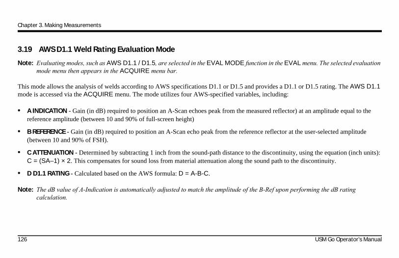
Chapter 3. Making Measurements
3.19 AWS D1.1 Weld Rating Evaluation Mode
Note: Evaluating modes, such as AWS D1.1 / D1.5, are selected in the EVAL MODE function in the EVAL menu. The selected evaluation mode menu then appears in the ACQUIRE menu bar.
This mode allows the analysis of welds according to AWS specifications D1.1 or D1.5 and provides a D1.1 or D1.5 rating. The AWS D1.1 mode is accessed via the ACQUIRE menu. The mode utilizes four AWS-specified variables, including:
• A INDICATION - Gain (in dB) required to position an A-Scan echoes peak from the measured reflector) at an amplitude equal to the reference amplitude (between 10 and 90% of full-screen height)
• B REFERENCE - Gain (in dB) required to position an A-Scan echo peak from the reference reflector at the user-selected amplitude (between 10 and 90% of FSH).
• C ATTENUATION - Determined by subtracting 1 inch from the sound-path distance to the discontinuity, using the equation (inch units): C = (SA–1) × 2. This compensates for sound loss from material attenuation along the sound path to the discontinuity.
• D D1.1 RATING - Calculated based on the AWS formula: D = A-B-C.
Note: The dB value of A-Indication is automatically adjusted to match the amplitude of the B-Ref upon performing the dB rating calculation.
126 USM Go Operator’s Manual

Chapter 3. Making Measurements
3.19 AWS D1.1 Weld Rating Evaluation Mode (cont.)
Before activating the AWS D1.1/D1.5 weld rating mode, be sure that all instrument settings are properly adjusted for the specific measurement application. Then access the AWS D1.1 submenu in the ACQUIRE menu, and follow this procedure:
1. Apply couplant and couple the probe to a suitable reference test standard.
2. Ensure that Gate A is positioned over the desired echo. Then, adjust the gain until the peak of the desired reference echo reaches the desired amplitude. Note that if the echo peak amplitude (A%A) does not fall between 10% and 90% of FSH, the point will not be accepted.
3. Use the B REFERENCE function to define the reference dB level.
4. To evaluate a reflector in a test piece, couple the probe to the test piece. Now adjust the Gate A position, if required, so that it is over the desired echo.
5. Adjust the gain until the peak of the test-piece echo reaches the desired screen height.
Note: The dB value recorded for A-Indication is automatically adjusted based on the amplitude difference between it and the value recorded for B-REF. It will usually not match the instrument dB gain setting.
6. With the AWS D1.1 SETUP submenu displayed, note that the A, C, and D parameters automatically update to match the Gate A triggering echo. Use the A INDICATION function to HOLD the current parameters. Note that the displayed RESULTS continue to update while the A, C, and D parameters are held.
USM Go Operator’s Manual 127

Chapter 3. Making Measurements
3.20 JISDAC Evaluation Mode
Note: Evaluation modes, such as JISDAC, are selected in the EVAL MODE function in the EVAL menu. The selected evaluation mode menu then appears in the ACQUIRE menu bar. While operating in JISDAC mode, the Gate A TOF MODE must be set to PEAK or JFLANK.
Conventional measurements can be made using the JIS Distance Amplitude Correction (JISDAC) mode. This mode operates based on a set of user-recorded data points. These points are recorded from the JIS/DAC menu, as described below.
The JISDAC mode displays all echoes at their true amplitude. However, when operating in JISDAC mode, a Distance Amplitude Correction curve is superimposed on the A-Scan display. The curve represents constant reflector size at varying material depth.
When displayed, the JISDAC curve visually represents a line of constant reflector peaks over a range of material depths. Remember that in JISDAC mode, the only deviation from traditional display and operation is the appearance of the JISDAC curve and a series of OFFSET curves. All A-Scan echoes are displayed at their non-compensated height. A JISDAC curve can be based on up to 15 data points(i.e. material depths). A JISDAC curve is programmed using a series of same-reflector echoes at various depths, covering the range of depths to be inspected in the test material. Because near field and beam spread vary according to transducer size and frequency, and materials vary in attenuation and velocity, JISDAC must be programmed differently for different applications.
The dynamic range of the JISDAC function is 60 dB, and the maximum curve slope is 12 dB per microsecond. Successive data points do not have to progressively decrease in amplitude. That is, the JISDAC curve does not have to have a constantly descending slope.
128 USM Go Operator’s Manual

Chapter 3. Making Measurements
3.20.1 Recording the JISDAC Curve
JISDAC Curve points are typically taken from a standard with equally-sized reflectors (holes) located at various material depths. The primary echo from each of these points, for a total of up to 15 echoes, are recorded. When JISDAC is active, the instrument displays a line that represents echo peaks for constant reflectors at varying material depth. This line is drawn as either a curved (linear in gain) line based on a series of collected JISDAC points or a series of straight line segments that join these JISDAC points. Only one JISDAC curve can be stored at a time. To program the JISDAC Curve:
1. Access the JISDAC menu, and select the RECORD submenu .
2. Couple the probe to the first reference point and adjust Gate A so that it is broken by the primary echo. If necessary, use the Gain Toggle to adjust the gain so that the echo crosses Gate A and the highest peak in Gate A is at approximately 80% of full-screen height. The highest peak must not be higher than 100% full-screen height.
Note: The AUTO 80 function automatically adjusts the gain to set the Gate A triggering echo to 80% of full screen height. If desired, select the AUTO 80 function in the RECORD submenu.
3. While the Gate is lined up over the first reference echo, activate the RECORD function. When the value of the RECORD function changes from 0 to 1, you have recorded the first JISDAC Curve point. Note that the first JISDAC point is treated as the reference echo. The amplitude value at which this point is recorded becomes the “reference amplitude” value.
USM Go Operator’s Manual 129

Chapter 3. Making Measurements
3.20.1 Recording the JISDAC Curve (cont.)
Note: When the first JISDAC reference point is stored, two measurement result boxes will be automatically set (if not already configured) to display SA and A%A values.
4. Continue to record additional curve points, up to a maximum of 15 points (note that at least two JISDAC Curve points are required).
5. When all of your points have been entered, select the FINISH function.
3.20.2 Working with JISDAC
In JISDAC mode, the instrument uses the user-input reference points to create a curve representing the amplitudes of echoes representing same-size reflectors at varying material depth. To turn JISDAC evaluation mode ON or OFF:
1. With the JISDAC menu accessed, select the SETUP submenu.
2. Use the JISDAC function to select ON or OFF. The JISDAC Curve is displayed whenever the feature is turned ON.
130 USM Go Operator’s Manual

Chapter 3. Making Measurements
3.20.2a Interpreting JISDAC Lines and Classes
The JISDAC display contains a recorded reference line and five fixed offset lines. Three of the lines are labeled as follows:
• H Line – Connects the recorded reference points
• M Line – Fixed offset positioned 6 dB below the H line
• L Line – Fixed offset positioned 12 dB below the H line
Any one of these three lines can be identified as the reference from which measurements are based (see the BOLD LINE function below). In addition, the remaining three offset lines are drawn at 6, 12, and 18 dB above the H line.
The regions of the A-Scan display bordered by the H, M, and L lines are identified with JIS Class numbers. These identifying numbers can also be displayed as results. CLS reports the region that contains the peak of the Gate A triggering echo.
USM Go Operator’s Manual 131

Chapter 3. Making Measurements
3.20.2b Defining a BOLD LINE Measurement Reference (JISDAC-SETUP-BOLD LINE)
The user-defined measurement reference is selected as follows:
1. Access the SETUP submenu in the JISDAC menu.
2. Use the BOLD LINE function to select the H, M, or L line.
3. Note that the selected line is now shown in bold on the A-Scan display. This line now serves as the reference level from which all reference measurements (such as A%rA or dBrB) are made.
3.20.2c Setting TRANSFER CORRection (JISDAC-MAT ATTN-TRANSFER CORR)
The TRANSFER CORR function applies dB compensation for the difference in coupling conditions between the known standard and the test piece.
1. Access the MAT ATTN submenu in the JISDAC menu.
2. Adjust the TRANSFER CORR function as required to compensate for coupling differences.
Note: When TRANSFER CORR is set to any value other than 0, the displayed gain value appears in a contrasting color, indicating that the amount of applied gain differs from the listed “instrument” gain.
132 USM Go Operator’s Manual

Chapter 3. Making Measurements
3.20.3 Deleting a JISDAC Curve
To delete a stored JISDAC curve:
1. With the JISDAC menu activated, select the SETUP submenu.
2. Activate the DELETE CURVE function, and then confirm your selection.
3. The entry in the JISDAC function box changes to OFF.
USM Go Operator’s Manual 133

Chapter 3. Making Measurements
3.21 CNDAC Evaluation Mode
Note: Evaluation modes, such as CNDAC, are selected in the EVAL MODE function in the EVAL menu. The selected evaluation ode menu appears in the ACQUIRE menu bar. While operating in CNDAC mode, the Gate A TOF MODE must be set to PEAK.
Conventional measurement can be made using the CN Distance Amplitude Correction (CNDAC) mode. This mode operates based on a set of user-recorded data points. These points are recorded from the CNDAC menu, as described below.
The CNDAC mode displays all echoes at their true amplitude. However, when operating in CNDAC mode, three addition lines, RL, SL, and EL, are superimposed on the A-Scan display. These curves represent constant reflector seize at varying material depth.
3.21.1 Recording the CNDAC Curve
CNDAC Curve points are typically recorded from a standard with equally-sized reflectors (holes) located at the various material depths. The primary echoes from each of these points, for a total of up to 16 echoes, are recorded. Only one CNDAC curve can be stored at a time. To program the DAC curve, proceed as follows:
1. Access the CNDAC menu, and select the RECORD submenu.
2. Couple the probe to the first reference point and adjust Gate A so that the primary echo passes through it. If necessary, use the Gain Toggle to adjust the gain so that the echo passes through Gate A and the highest peak in Gate A is at approximately 80% of full-screen height. The highest peak must not be higher than 100% full-screen height.
134 USM Go Operator’s Manual

Chapter 3. Making Measurements
3.21.1 Recording the CNDAC Curve (cont.)
Note: The AUTO80 function automatically adjusts the gain to set the Gate A triggering echo to 80% of full-screen height. If desired, select the AUTO80 function in the RECORD submenu.
3. While the Gate is lined up over the first reference echo, activate the RECORD function. When the value of the RECORD function changes from 0 to 1, you have recorded the first CNDAC curve point. Note that the first CNDAC point is treated as the reference echo. The amplitude value at which this point is recorded becomes the “reference amplitude” value.
4. Continue to record additional curve points, up to the maximum of 16 points. Note that at least two CNDAC curve points are required.
5. When all of your points have been entered, activate the FINISH function.
3.21.2 Working with CNDAC Curves
To turn CNDAC evaluation mode ON or OFF:
1. Access the CNDAC menu, and select the SETUP submenu.
2. Use the CNDAC MODE function to select ON or OFF. Three addition lines appear when the feature is turned on.
USM Go Operator’s Manual 135

Chapter 3. Making Measurements
3.21.2a Showing CNDAC Curve
By default, the CNDAC curve is hidden after the curve is recorded. To show the line:
1. Access the CNDAC menu, and select the SETUP submenu.
2. Use the CNDAC DISPLAY function to select ON or OFF. The CNDAC curve is displayed when the feature is turned on.
3.21.2b Setting Three Addition Lines: RL, SL, EL
Three addition lines are displayed after the CNDAC curve is recorded. To adjust the offset of these three lines:
1. Access the CNDAC menu, and select the LINE submenu.
2. Adjust RL, SL, and EL parameters to set the offset of the line.
136 USM Go Operator’s Manual
Chapter 3. Making Measurements
3.21.2c Setting Transfer Correction (CNDAC-LINE-TRANSFER CORR)
The TRANSFER CORR function applies dB compensation for the difference in coupling conditions between the known standard and the test piece.
1. Access the CNDAC menu, and select the LINE submenu.
2. Adjust the TRANSFER CORR function as required to compensate for coupling differences.
Note: When TRANSFER CORR is set to any value other than 0, the displayed gain value appears in a contrasting color, indicating that the amount of applied gain differs from the listed “instrument” gain.
3.21.2d Deleting a CNDAC Curve
To delete a CNDAC curve:
1. Access the CNDAC menu, and select the SETUP submenu.
2. Activate the DELTE CURVE function, and then confirm your selection.
USM Go Operator’s Manual 137

Chapter 3. Making Measurements
3.22 Backwall Echo Attenuation
The Backwall Echo Attenuation option enables the operator to set a separate gain for the gate range of gate B. This gain is independent of the gain for the rest of the test range. The Backwall Echo Attenuation therefore enables a selective attenuation or peaking of the echoes in the B gate. A typical application case for the Backwall Echo Attenuation is forging testing. In this application case, the gain is reduced in gate B until the backwall echo is completely displayed in the A-scan. The user can then selectively integrate the backwall echo into the flaw evaluation.
Figure 15: Backwall Echo Attenuation
138 USM Go Operator’s Manual

Chapter 3. Making Measurements
3.22 Backwall Echo Attenuation (cont.)
However, the Backwall Echo Attenuation option also allows to systematically increase the gain. In this way, the operator can, for example, only increase the gain within the flaw expectancy range in order to peak the echo in this range.
Note: The Backwall Echo Attenuation has no effect on the evaluation of the echoes in the B gate. The echo evaluation continues to refer to the actually measured signals. All other gate-related functions, such as gate alarm or TTL assignment remain unaffected as well.
USM Go Operator’s Manual 139

Chapter 3. Making Measurements
3.22.1 BEA
1. In the CONFIG3 menu, activate the BEA submenu.
2. Use the joystick to select the BEA function, and then press the center of the joystick to activate the function.
3. Move the joystick left/right to turn on/off the BEA option.
4. Press the center of the joystick again to save the setting.
Figure 16: CONFIG3 Menu with BEA Activated
140 USM Go Operator’s Manual

Chapter 3. Making Measurements
3.22.2 BW Gain
You can set the separate gain for the echoes in gate B in this function. The gain may be situated both above and below the gain in the rest of the test range. The setting range for the gain is between 0.0 and 110.0 dB.
1. In the CONFIG3 menu, activate the BEA submenu.
2. Use the joystick to select BW GAIN function, and then press the center of joystick to activate the function.
3. Move the joystick left/right to set the gain for gate B.
4. Press the center of the joystick again to save the setting.
USM Go Operator’s Manual 141

Chapter 3. Making Measurements
142 USM Go Operator’s Manual

Chapter 4. Data Sets & Reports
Chapter 4. Data Sets & Reports
The USM Go can store data set files and generate reports. To perform these functions, see Figure 17 below and proceed with this chapter.
Figure 17: The FILES Menu
USM Go Operator’s Manual 143

Chapter 4. Data Sets & Reports
4.1 The FILES MenuTo access the FILES menu and select the desired function, refer to Figure 17 on page 143 and complete the following steps:
1. In the SETUP menu, activate the FILES submenu using the joystick ( ).
2. Use the joystick ( ) to select the function titled ACTION. Press the center of the joystick ( ) to activate the function.
3. Move the joystick left or right ( ) to select one of the following actions:
• STORE DATASET - see “Storing a New Data Set File” on page 145
• RECALL DATASET - see “Recalling a Data Set File” on page 147
• DELETE DATASET - see “Deleting a Data Set File” on page 148
• STORE REPORT - see “Storing a Report” on page 156
• FAST REPORT - see “Fast Report” on page 157
4. After making your choice, press the center of the joystick ( ) to deactivate the function.
144 USM Go Operator’s Manual

Chapter 4. Data Sets & Reports
4.2 Working With Data Set Files
The current instrument settings, which includes most of the functional settings, can be stored as a data set file. When a stored data set file is later recalled, all active function settings are modified to match those contained in the data set file. Also, if the A-Scan was stored in the data set file, it is displayed and frozen on the display screen. After a data set is recalled, the newly active functional settings may then be modified if desired. To perform data set operations:
After a data set file is recalled, the instrument settings may then be modified, but these changes only affect the stored data set file if the new setting are stored with the same file name as the original data set file.
Note: The USM Go data set files can be recognized by the “.UGO” extension on the filenames.
4.2.1 Storing a New Data Set File
After selecting the STORE DATASET action (see “The FILES Menu” on page 144), proceed to the appropriate section on the following page to either create a new file name or select an existing file name.
USM Go Operator’s Manual 145

Chapter 4. Data Sets & Reports
4.2.1a File Selection Mode
1. Use the joystick ( ) to select the function titled FILENAME. Press the center of the joystick once ( ) to activate the function in File Selection mode.
2. Move the joystick up or down ( ) to select the desired file name from the list of SD card files.
3. Press the center of the joystick ( ) to deactivate the function.
4.2.1b File Naming Mode
1. Use the joystick ( ) to select the function titled FILENAME. Press the center of the joystick twice ( ) to activate the function in File Naming mode.
2. Move the joystick up or down ( ) to choose the first character in the desired file name. Then, move the joystick left or right
( ) to move the cursor to another character position in the text string. Repeat the process until you have entered the entire file name.
3. Press the center of the joystick ( ) to deactivate the function.
146 USM Go Operator’s Manual

Chapter 4. Data Sets & Reports
4.2.2 Recalling a Data Set File
After selecting the RECALL DATASET action (see “The FILES Menu” on page 144), continue as follows:
1. Use the joystick ( ) to select the function titled FILENAME. Press the center of the joystick ( ) to activate the function in File Selection mode.
2. After the list of data set files available on the SD card is displayed, move the joystick up or down ( ) to select the desired data set file name from the list.
3. After selecting the desired data set file, press the center of the joystick ( ) to deactivate the function.
USM Go Operator’s Manual 147
Chapter 4. Data Sets & Reports
4.2.3 Deleting a Data Set File
After selecting the DELETE DATASET action (see “The FILES Menu” on page 144), continue as follows:
1. Use the joystick ( ) to select the function titled FILENAME. Press the center of the joystick ( ) to activate the function.
2. Move the joystick up or down ( ) to choose the first character in the desired filename. Then, move the joystick left or right
( ) to move the cursor to a different character position in the text string.
3. Repeat step 2 until you have entered the entire file name. Then, press the center of the joystick ( ) to deactivate the function.
148 USM Go Operator’s Manual

Chapter 4. Data Sets & Reports
4.2.4 Editing a Data Set File
Editing an existing data set file, requires a simple combination of the procedures described in the previous sections:
1. Recall the data set file that you wish to edit (see “Recalling a Data Set File” on page 147).
2. Using the methods described in previous chapters, modify the active functional settings as desired.
3. Store the modified settings as a data set file (see “Storing a New Data Set File” on page 145). When choosing a filename, overwrite the original data set file by choosing the same filename for the modified settings.
USM Go Operator’s Manual 149
Chapter 4. Data Sets & Reports
4.3 Creating a Memo (Smart Notes)
The USM Go places a folder, “MEMO”, at the current working directory. The user can load a memo text file from this folder. In addition, the user can create a new memo text file and save the file in this folder, for future editing on a PC. Each file contains 5 lines and each line has 31 characters.Memos may be attached to Data Set Files at the time the files are stored or to Reports at the time they are generated. After a file is stored, the attached memo may be modified. To create or edit a memo:
1. In the SETUP menu, activate the FILES submenu using the joystick ( ).
2. Use the joystick ( ) to select the function titled MEMO EDIT. Press the center of the joystick ( ) to activate the function.
3. Use the joystick to browse the SD card and select a memo text file.
4. Select NEW MEMO, and press the center of the joystick ( ) to create a new memo text file.
5. Use the joystick ( ) to enter the memo text file's name.
6. Move the joystick left/right ( ) to move the cursor position and up/down ( ) to change the character.
150 USM Go Operator’s Manual

Chapter 4. Data Sets & Reports
4.3 Creating a Memo (Smart Notes) (cont.)
7. Once you have entered the file name, press the center of the joystick to enter the Edit mode. An empty memo file is created. Now the user can modify the content.
8. To modify the content, move joystick left/right ( )to move the cursor and up/down( )to change the character.
9. Press the center of the joystick again to exit the Edit mode.Then, press the center of the joystick ( ) to deactivate the function.
To edit an existing memo file:
10. Move the joystick up/down( )to select a stored memo text file.
11. Press the center of the joystick ( )to enter edit mode. The content of the selected memo text file appears on the screen.
12. To modify the content, move the joystick left/right ( )to move the cursor and up/down( ) to change the character.
13. Press the center of joystick again to exit Edit mode. The modification will be saved automatically, and the selected memo text file's name appears on the screen.
14. Press the center of the joystick ( ) to deactivate the function.
USM Go Operator’s Manual 151

Chapter 4. Data Sets & Reports
4.4 Including a Memo in a Report
After creating a memo, you can specify whether that memo is included in a report. To add or remove a memo from a report:
1. In the SETUP menu, activate the FILES submenu using the joystick ( ).
2. Use the joystick ( ) to select the function titled MEMO IN REPORT. Press the center of the joystick ( ) to activate the function.
3. Move the joystick left or right ( ) to select one of the following options:
• YES - the memo is included with a report
• NO - the memo is not included with a report
4. After making your choice, press the center of the joystick ( ) to deactivate the function.
152 USM Go Operator’s Manual

Chapter 4. Data Sets & Reports
4.5 Creating a Report Header
The USM Go places a folder, “MEMO”, at the current working directory. The user can load a memo text file from this folder. In addition, the user can create a new memo text file and save the file in this folder, for future editing on a PC. Each file contains 5 lines and each line has 31 characters.Memos may be attached to Data Set Files at the time the files are stored or to Reports at the time they are generated. After a file is stored, the attached memo may be modified.
.Report Headers are attached to data set files at the time the files are stored. After a file is stored, the attached Report Header may be edited. To create or edit a Report Header:
1. In the SETUP menu, activate the FILES submenu using the joystick ( ).
2. Use the joystick ( ) to select the function titled HEADER EDIT. Press the center of the joystick ( ) to activate the function.
3. A text area for the header is now available on the display, with the cursor positioned for the first character. Move the joystick up or
down ( ) to enter the first character in the header. Then, move the joystick left or right ( ) to move the cursor to a different character position in the text string.
4. Repeat step 3 until you have entered the entire header (nine characters maximum). Then, press the center of the joystick ( ) to deactivate the function.
USM Go Operator’s Manual 153

Chapter 4. Data Sets & Reports
4.6 Including a Header in a Report
After creating a header, you can specify whether that header is included in a report. To add or remove a header from a report:
1. In the SETUP menu, activate the FILES submenu using the joystick ( ).
2. Use the joystick ( ) to select the function titled HDR IN REPORT. Press the center of the joystick ( ) to activate the function.
3. Move the joystick left or right ( ) to select one of the following options:
• YES - the header is included with a report
• NO - the header is not included with a report
4. After making your choice, press the center of the joystick ( ) to deactivate the function.
154 USM Go Operator’s Manual

Chapter 4. Data Sets & Reports
4.7 Creating a Report
IMPORTANT: Before proceeding be sure an SD card is installed in the instrument (see “Using the SD Slot, USB Connector & I/O Connector” on page 14).
A report, with contents specified by the user, can be generated and stored on the USM Go SD card. The following features of the active data set file can either be omitted from or included in the report:
• Header (use the HDR IN REPORT function)
• Memo (use the MEMO IN REPORT function)
• A-Scan Image (use the IMAGE IN REPORT function)
• Instrument parameters (use the PARAM IN REPORT function)
After configuring the report as desired, proceed to the next page to store the report.
USM Go Operator’s Manual 155

Chapter 4. Data Sets & Reports
4.8 Storing a Report
To store the report specified in the previous section:
Note: If you have chosen to store the A-Scan image with the report, the image will be saved as a JPG file.
1. Use the joystick ( ) to select the function titled FILENAME. Press the center of the joystick ( ) to activate the function.
2. Move the joystick up or down ( ) to choose the first character in the desired filename. Then, move the joystick left or right
( ) to move the cursor to a different character position in the text string.
3. Repeat step 2 until you have entered the entire file name. Then, press the center of the joystick ( ) to deactivate the function.
4. If you have not already done so, assign the COPY function to one of the Function Toggle buttons (see “Defining Function Toggle Actions” on page 47). Your report can now be saved by pressing the assigned toggle button, whenever you are in Acquisition Mode and the cursor is in the menu bar or the full-screen display is active.
156 USM Go Operator’s Manual

Chapter 4. Data Sets & Reports
4.9 Fast Report
The Fast Report option performs the same basic function as the Store Report option. The difference is that, if you save the A-Scan screen image along with the report, the image is saved as a bitmap file. This permits the save operation to be completed significantly faster, but you should be aware that some SD card printers may not recognize the bitmap file. To use the Fast Report option:
1. Use the joystick ( ) to select the function titled FILENAME. Press the center of the joystick ( ) to activate the function.
2. Move the joystick up or down ( ) to choose the first character in the desired filename. Then, move the joystick left or right
( ) to move the cursor to a different character position in the text string.
3. Repeat step 2 until you have entered the entire file name. Then, press the center of the joystick ( ) to deactivate the function.
4. If you have not already done so, assign the COPY function to one of the Function Toggle buttons (see “Defining Function Toggle Actions” on page 47). Your report can now be saved by pressing the assigned toggle button, whenever you are in Acquisition Mode and the cursor is in the menu bar or the full-screen display is active.
USM Go Operator’s Manual 157

Chapter 4. Data Sets & Reports
4.10 Parameters Summary
The user can browse all the parameters setting in the summary report.
1. In the FILE menu, activate the REPORT submenu.
2. Use the joystick to select the PARAMETERS SUMMARY function, and then press the center of joystick ( ) to activate the function.
3. All the parameters are listed on the screen. Move the joystick up/down ( ) to see other pages.
4. Press the Function 2 key to save the report to the SD card.
158 USM Go Operator’s Manual

Chapter 5. Data Recorder Files
Chapter 5. Data Recorder Files
The Data Recorder (DR) menu functions are shown in Figure 18 below.
Figure 18: The DR Menu
USM Go Operator’s Manual 159

Chapter 5. Data Recorder Files
5.1 Naming the Data Recorder File
In the SETUP menu, use the joystick ( ) to activate the DR menu (see Figure 18 on page 159). Then, proceed to the appropriate section below to either create a new file name or select an existing file name.
5.1.1 File Selection Mode
1. Use the joystick ( ) to select the function titled FILENAME in the DR SETUP submenu. Press the center of the joystick once
( ) to activate the function in File Selection mode.
2. Move the joystick up or down ( ) to select the desired file name from the list of SD card files.
3. Press the center of the joystick ( ) to deactivate the function.
160 USM Go Operator’s Manual

Chapter 5. Data Recorder Files
5.1.2 File Naming Mode
1. Use the joystick ( ) to select the function titled FILENAME in the DR SETUP submenu. Press the center of the joystick twice
( ) to activate the function in File Naming mode.
2. Move the joystick up or down ( ) to choose the first character in the desired file name. Then, move the joystick left or right
( ) to move the cursor to another character position in the text string. Repeat the process until you have entered the entire file name.
3. Press the center of the joystick ( ) to deactivate the function.
USM Go Operator’s Manual 161
Chapter 5. Data Recorder Files
5.2 Configuring the Data Recorder File
After entering a name for the data recorder file, the following parameters must be specified:
• TOP - the coordinates of the first cell in the file, using a row number and an column letter (e.g. 1A).
• BOTTOM - the coordinates of the last cell in the file, using a row number and an column letter (e.g. 10B).
• ADV DIRECTION - specifies the direction (DOWN or RIGHT) in which the DR advances after each thickness reading is recorded.
Use the usual joystick methods to select each of the above functions and program the desired values.
5.3 Creating the Data Recorder File
1. After naming and configuring the DR file, use the joystick ( ) to select the function titled CREATE.
2. Press the center of the joystick ( ) to create and activate a DR file that uses your previous selections.
IMPORTANT: After the DR file is created, the TOP and BOTTOM parameters cannot be changed. In fact, these functions are replaced on the menu with listings of the NUM OF COLS and NUM OF ROWS, respectively.
162 USM Go Operator’s Manual

Chapter 5. Data Recorder Files
5.4 Viewing the Data Recorder File
To view the DR file that you have just activated, you must complete the following steps:
1. In the SETUP menu, activate the DR submenu using the joystick ( ).
2. Use the joystick ( ) to select the function titled DR VIEW. Then, press the center of the joystick ( ) to activate the function.
3. Move the joystick left or right ( ) to select the ON option. Then, press the center of the joystick ( ) to deactivate the function.
4. Press and hold the center of the joystick ( ) to switch to the Acquire Menu.
5. When in Acquire Mode, press the center of the joystick ( ) to enter the full-screen display mode.
As shown in Figure 19 on page 164, the DR file is displayed on the right side of the display screen.
USM Go Operator’s Manual 163
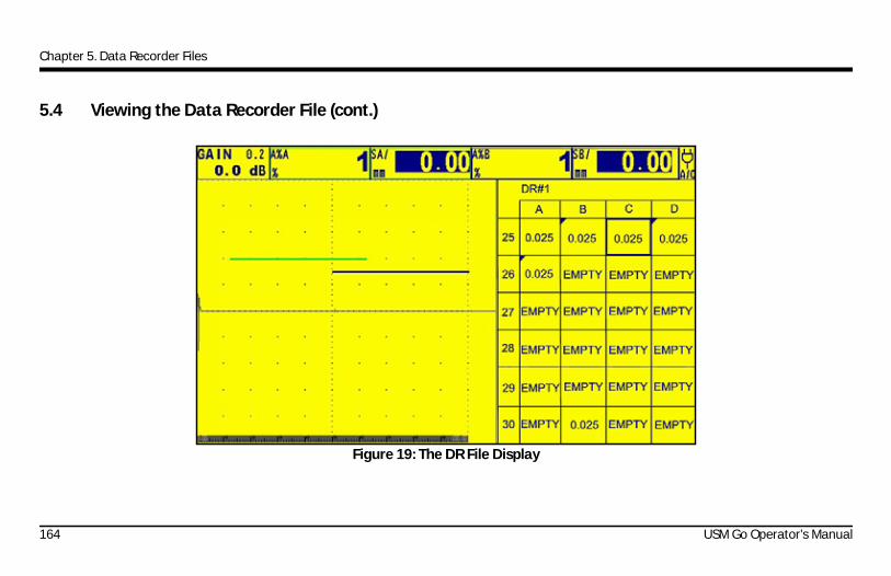
Chapter 5. Data Recorder Files
5.4 Viewing the Data Recorder File (cont.)
Figure 19: The DR File Display
164 USM Go Operator’s Manual
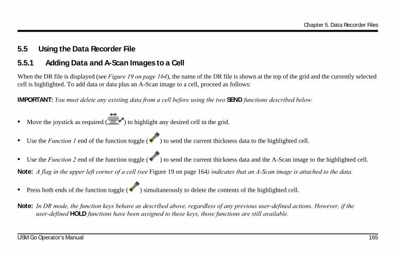
Chapter 5. Data Recorder Files
5.5 Using the Data Recorder File
5.5.1 Adding Data and A-Scan Images to a Cell
When the DR file is displayed (see Figure 19 on page 164), the name of the DR file is shown at the top of the grid and the currently selected cell is highlighted. To add data or data plus an A-Scan image to a cell, proceed as follows:
IMPORTANT: You must delete any existing data from a cell before using the two SEND functions described below.
• Move the joystick as required ( ) to highlight any desired cell in the grid.
• Use the Function 1 end of the function toggle ( ) to send the current thickness data to the highlighted cell.
• Use the Function 2 end of the function toggle ( ) to send the current thickness data and the A-Scan image to the highlighted cell.
Note: A flag in the upper left corner of a cell (see Figure 19 on page 164) indicates that an A-Scan image is attached to the data.
• Press both ends of the function toggle ( ) simultaneously to delete the contents of the highlighted cell.
Note: In DR mode, the function keys behave as described above, regardless of any previous user-defined actions. However, if the user-defined HOLD functions have been assigned to these keys, those functions are still available.
USM Go Operator’s Manual 165
Chapter 5. Data Recorder Files
5.5.2 Previewing A-Scan Images in a Cell
When you select a cell in the DR file that has an A-Scan image attached, the attached image is loaded and the instrument displays a frozen preview of the saved image with the corresponding gate positions (see Figure 20 on page 167).
While a frozen A-Scan image is displayed, no new data is taken until you resume live data input by one of the following actions:
• Delete both the stored data and the attached A-Scan image from selected the cell
• Navigate to an empty cell
As soon as one of the above actions is taken, the instrument unfreezes and resumes taking data in the manner specified by the current setup configuration.
166 USM Go Operator’s Manual
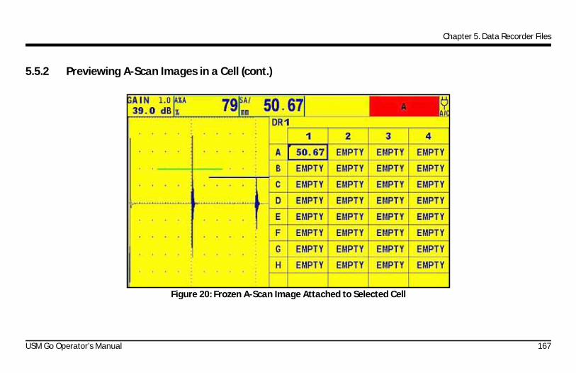
Chapter 5. Data Recorder Files
5.5.2 Previewing A-Scan Images in a Cell (cont.)
Figure 20: Frozen A-Scan Image Attached to Selected Cell
USM Go Operator’s Manual 167

Chapter 5. Data Recorder Files
5.6 Live Video Record Files
5.6.1 Video Record Temporary Source and Destination
The user can set the source and destination of a video record temporary file. The options are memory and the SD card. If the memory is selected, the recording frequency is 50 Hz. If the SD card is selected, the recording frequency is 10 Hz.
1. In the FILE menu, activate VIDEO submenu.
2. Use the joystick ( ) to select SOURCE/DEST function, and then press the center of the joystick ( ) to activate the function.
3. Move the joystick to choose MEMORY or SD CARD.
4. Press the center of the joystick ( ) to save the setting.
168 USM Go Operator’s Manual

Chapter 5. Data Recorder Files
5.6.2 Video Record Mode
Users can select two different modes, RECORD and REPLAY, for live video recording.
1. In the FILE menu, activate the VIDEO submenu.
2. Use the joystick ( ) to select the MODE function, and then press the center of the joystick ( ) to activate the function.
3. Move the joystick to choose RECORD or REPLAY.
4. Press the center of the joystick ( ) to save the setting.
USM Go Operator’s Manual 169

Chapter 5. Data Recorder Files
5.6.3 Video Record Filename
When in record mode, the user can select the existing file on the SD card or enter a new filename. When in replay mode, the user can only select the existing file on the SD card.
5.6.3a Record Mode
1. In the FILE menu, activate the VIDEO submenu.
2. Use the joystick ( ) to select the FILENAME function, and then press the center of the joystick ( ) to activate the function.
3. Move the joystick up/down to select the existing file on SD card.
4. When the filename shows “<NEW FILE>”, press the center of the joystick ( ) to enter a new filename.
5. When an existing file is selected, press the center of the joystick ( )to modify the filename.
6. Press the center of the joystick ( ) to exit the FILENAME edit mode.
170 USM Go Operator’s Manual

Chapter 5. Data Recorder Files
5.6.3b Replay Mode
1. In the FILE menu, activate the VIDEO submenu.
2. Use the joystick to select the FILENAME function, and then press the center of the joystick ( ) to activate the function.
3. Move the joystick up/down ( ) to select the existing file on SD card.
4. Press the center of the joystick ( ) to select the file.
USM Go Operator’s Manual 171

Chapter 5. Data Recorder Files
5.6.4 Live Video Record File Record Mode
Enter Record Mode
1. In the FILE menu, activate the VIDEO submenu.
2. Set the MODE as RECORD and FILENAME.
3. Use the joystick to select ENTER function, and then press the center of the joystick ( ) to enter the record mode.
Start/Pause Recording
1. In the RECORD menu, use the joystick to select the RECORD function.
2. Move the joystick left/right ( ) to start or pause recording.
During the recording, the user can change only the gain value and gate. All these changes will be saved at the same time.
Stop Recording
1. In the RECORD menu, use the joystick to select the STOP function.
2. Move the joystick left/right ( ) to exit RECORD mode.
172 USM Go Operator’s Manual

Chapter 5. Data Recorder Files
Add a Flag
The live video record file supports a flag feature. The user can set a flag during recording. Then, when replaying a record file, the user can get the flagged frame directly.
1. In the RECORD menu, use the joystick to select the FLAG function during recording.
2. Move the joystick to set the current frame flagged.
Exit Record Mode
1. Move the joystick to select the menu bar.
2. Press the center of the joystick ( ) to exit RECORD mode.
USM Go Operator’s Manual 173

Chapter 5. Data Recorder Files
5.6.5 Live Video Record File Replay Mode
5.6.5a Enter Replay Mode
1. In the FILE menu, activate the VIDEO submenu.
2. Set the MODE as REPLAY and FILENAME.
3. Use the joystick to select the ENTER function, and then press the center of the joystick ( ) to enter the REPLAY mode.
5.6.5b Start/Pause Replaying
1. In the REPLAY menu, use the joystick to select the PLAY parameter.
2. Move the joystick left/right ( ) to start or pause replaying.
5.6.5c Stop Replaying
1. In the REPLAY menu, use the joystick to select the STOP parameter.
2. Move the joystick left/right ( ) to exit the REPLAY mode.
174 USM Go Operator’s Manual

Chapter 5. Data Recorder Files
5.6.5d Change Replay Speed
1. In the REPLAY menu, use the joystick to select the SPEED parameter.
2. Move the joystick left/right ( ) to select SPEED.
5.6.5e Browse the Record File by Time
The user can browse the record file by changing the time.
1. In the REPLAY menu, use the joystick to select the TIME parameter.
2. Move the joystick left/right ( ) to change TIME. The corresponding frame will be replayed on the screen.
USM Go Operator’s Manual 175

Chapter 5. Data Recorder Files
5.6.5f Browse the Record File by Frame
The user can browse the record file by changing the frame.
1. In the REPLAY menu, use the joystick to select the FRAME parameter.
2. Move the joystick left/right ( ) to change FRAME. The corresponding frame will be replayed on the screen.
5.6.5g Browse the Record File's Flag
The user can browse the flag stored in the record file.
In the FLAG menu, use the joystick to select the FLAG parameter. The flagged frame will be replayed on the screen automatically.
5.6.5h Exit Replay Mode
1. Move the joystick ( ) to select the menu bar.
2. Press the center of the joystick to exit the REPLAY mode.
176 USM Go Operator’s Manual
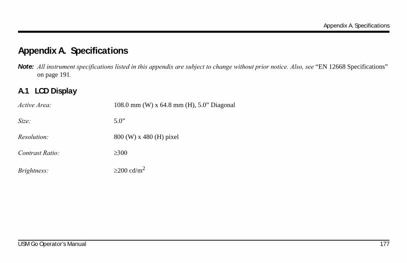
Appendix A. Specifications
Appendix A. Specifications
Note: All instrument specifications listed in this appendix are subject to change without prior notice. Also, see “EN 12668 Specifications” on page 191.
A.1 LCD Display
Active Area: 108.0 mm (W) x 64.8 mm (H), 5.0” Diagonal
Size: 5.0”
Resolution: 800 (W) x 480 (H) pixel
Contrast Ratio:
Brightness: 200 cd/m2
USM Go Operator’s Manual 177

Appendix A. Specifications
A.2 Connectors
Probe Connectors: 2, LEMO-00
UT Output Connector: SAP output, with an added ALARM pin
USB Interface: Micro USB connector
SD-Card Connector: Full-size SD card slot, accommodates all standard SD cards
Range: 14,016 mm (552”) for longitudinal wave in steel
Display Delay: -15 s to 3500 s
Probe Delay: 0 to 1000 s
Sound Velocity: 1000 to 16,000 m/s
PRF: Manually adjusted from 15 to 2000 Hz or automatically optimized,3 automatic adjustment modes: Auto Low, Auto Med, Auto High
178 USM Go Operator’s Manual

Appendix A. Specifications
A.3 Pulser
Note: All pulser measurements were taken according to EN12668 specifications.
Pulser Mode: Standard: simulated spikeOptional: uni-polar square wave via software control
Pulser Voltage (SQ Mode): 120 V to 300 V, with a 10 V step and tolerance of 10%
Pulser Falling/Rising Time: 10 ns maximum
Pulser Width (SQ Mode): 30 ns to 500 ns, with a 10 ns step and a tolerance of 10%
Pulser Amplitude (SQ Mode): Low: 120 VHigh: 300 V
Pulser Energy (Spike Mode): Low: 30 nSHigh: 100 nS
Damping: 50 ohms or 1000 ohms
USM Go Operator’s Manual 179

Appendix A. Specifications
A.4 Receiver
Digital Gain: Dynamic range of 110 dB, with a 0.2 dB step
Analog Bandwidth: 0.9 to 20 MHz
Equivalent Input Noise: <80 nV/ , across the full bandwidth
Recovery Time: < 10 us, according to EN12668 8.5.3 test
Input Linearity: 5% by method E317, for output data on all 4 ADCs
Filters: Broad Band: 1.1 to 20.44 MHz1-5 MHz: 0.9 to 5.14 MHz2, 2.25 MHz: 1.0 to 3.85 MHz4, 5 MHz: 2.43 to 7.92 MHz10 MHz: 6.27 to 13.6 MHz13, 15 MHz: 10.43 to 17.96 MHz
Hz
180 USM Go Operator’s Manual

Appendix A. Specifications
A.5 Gates
Independent Gates: 2 Gates (A and B), Gate B supports triggering by Gate A
Rectification: POS (positive)NEG (negative)FW (full wave)RF
Measurement: PeakFlankJ-Flank
A.6 Memory
Capacity: 2 GB, SD card
Data Sets:
Reports: jpg or bmp A-Scan images
USM Go Operator’s Manual 181
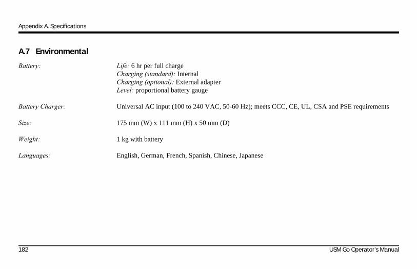
Appendix A. Specifications
A.7 Environmental
Battery: Life: 6 hr per full chargeCharging (standard): InternalCharging (optional): External adapterLevel: proportional battery gauge
Battery Charger: Universal AC input (100 to 240 VAC, 50-60 Hz); meets CCC, CE, UL, CSA and PSE requirements
Size: 175 mm (W) x 111 mm (H) x 50 mm (D)
Weight: 1 kg with battery
Languages: English, German, French, Spanish, Chinese, Japanese
182 USM Go Operator’s Manual

Appendix A. Specifications
A.8 Protection
Damp Heat & Humidity (Storage): 10 Cycles: 10 hr at +60°C down to +30°C, 10 hr at +30°C up to +60°C,Transition within 2 hr (507.4)
Temperature Shock (Storage): 3 Cycles: 4 hr at -20°C up to +60°C, 4 hr at +60°C,Transition within 5 minutes (503.4 Procedure II)
Vibration: General Exposure: 1 hr each axis, 514.5-5 Procedure I, Annex C, Figure 6
Shock: 6 Cycles each axis, 15 g, 11 ms, half-sine (516.5 Procedure I)
Loose Cargo (in Shipping Container): 514.5 Procedure II
Transit Drop (Packaged for Shipment): 26 Drops, 516.5 Procedure IV
Dust Proof/Dripping Water Proof: As per the IEC 529 specification for IP67 classification
Operating Temperature Range: 0 to 55°C
Storage Temperature Range: -20 to +60°C, 24 hr with battery
USM Go Operator’s Manual 183
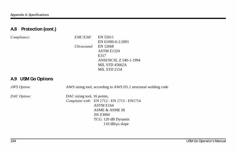
Appendix A. Specifications
A.8 Protection (cont.)
Compliance: EMC/EMI: EN 55011EN 61000-6-2:2001
Ultrasound: EN 12668ASTM E1324E317ANSI/NCSL Z 540-1-1994MIL STD 45662AMIL STD 2154
A.9 USM Go Options
AWS Option: AWS sizing tool, according to AWS D1.1 structural welding code
DAC Option: DAC sizing tool, 16 points,Complaint with: EN 1712 - EN 1713 - EN1714
ASTM E164ASME & ASME IIIJIS Z3060TCG: 120 dB Dynamic
110 dB/s slope
184 USM Go Operator’s Manual

Appendix A. Specifications
A.9 USM Go Options (cont.)
DGS Option: DGS sizing tool,Complaint with: EN 1712 - EN 1713 - EN1714
ASTM E164
Embedded Data Logger Option: Grid file creation
Square Wave Pulser Option: Allows fine-tuning of pulser parameters, Voltage adjustment from 120 to 300 V per 10 V steps,pulse width adjustment from 30 to 500 ns per 10 ns steps
BEA: Backwall Echo Attenuation.
Phantom Option: Phantom PRF will help to identify a ghost echo caused by multiple reflections in low-attenuation materials
USM Go Operator’s Manual 185

Appendix A. Specifications
[no content intended for this page - proceed to next page]
186 USM Go Operator’s Manual

Appendix B. Environmental Compliance
Appendix B. Environmental Compliance
This appendix contains information on the following topics:
• WEEE Directive (see Section B.1 on page 188)
• Battery disposal (see Section B.2 on page 189)
USM Go Operator’s Manual 187

Appendix B. Environmental Compliance
B.1 Waste Electrical and Electronic Equipment (WEEE) Directive
GE Sensing & Inspection Technologies is an active participant in Europe’s Waste Electrical and Electronic Equipment (WEEE) take-back initiative, directive 2002/96/EC.
The equipment that you bought has required the extraction and use of natural resources for its production. It may contain hazardous substances that could impact health and the environment.
In order to avoid the dissemination of those substances in our environment and to diminish the pressure on the natural resources, we encourage you to use the appropriate take-back systems. Those systems will reuse or recycle most of the materials of your end life equipment in a sound way.
The crossed-out wheeled bin symbol invites you to use those systems.
If you need more information on the collection, reuse and recycling systems, please contact your local or regional waste administration.
Visit www.ge.com/inspectiontechnologies for take-back instructions and more information about this initiative.
188 USM Go Operator’s Manual

Appendix B. Environmental Compliance
B.2 Battery Disposal
This product contains a battery that cannot be disposed of as unsorted municipal waste in the European Union. See the product documentation for specific battery information. The battery is marked with this symbol, which may include lettering to indicate cadmium (Cd), lead (Pb), or mercury (Hg). For proper recycling return the battery to your supplier or to a designated collection point.
B.2.1 What do the Markings Mean?
Batteries and accumulators must be marked (either on the battery or accumulator or on its packaging, depending on size) with theseparate collection symbol. In addition, the marking must include the chemical symbols of specific levels of toxic metals as follows:
• Cadmium (Cd) over 0.002%
• Lead (Pb) over 0.004%
• Mercury (Hg) over 0.0005%
USM Go Operator’s Manual 189

Appendix B. Environmental Compliance
B.2.2 The Risks and Your Role in Reducing Them
Your participation is an important part of the effort to minimize the impact of batteries and accumulators on the environment and on human health. For proper recycling you can return this product or the batteries or accumulators it contains to your supplier or to a designated collection point.
Some batteries or accumulators contain toxic metals that pose serious risks to human health and to the environment. When required, the product marking includes chemical symbols that indicate the presence toxic metals: Pb for lead, Hg for mercury, and Cd for cadmium.
• Cadmium poisoning can result in cancer of the lungs and prostate gland. Chronic effects include kidney damage, pulmonary emphysema, and bone diseases such as osteomalcia and osteoporosis. Cadmium may also cause anemia, discoloration of the teeth, and loss of smell (anosmia).
• Lead is poisonous in all forms. It accumulates in the body, so each exposure is significant. Ingestion and inhalation of lead can cause severe damage to human health. Risks include brain damage, convulsions, malnutrition, and sterility.
• Mercury creates hazardous vapors at room temperature. Exposure to high concentrations of mercury vapor can cause a variety of severe symptoms. Risks include chronic inflammation of mouth and gums, personality change, nervousness, fever, and rashes.
190 USM Go Operator’s Manual

Appendix C. EN 12668 Specifications
Appendix C. EN 12668 Specifications
The EN 12668 specifications for the USM Go are listed in Table 2 below.
Table 2: EN 12668-1:2000 Specifications Paragraph Parameter LSL Typ. USL Units Test Conditions
8.2 Timebase Stability Against Temperature -1 0 1 %FS/C After 30 minute warm-up
Amplitude Stability Against Temperature -5 0 5 %FS/C After 30 minute warm-up
9.3.2 Timebase Stability After Warm Up -1 0 1 %FS After 30 minute warm-up
Amplitude Stability After Warm Up -2 1 2 %FS After 30 minute warm-up
9.3.3 Timebase Display Jitter -1 0 1 %FS After 30 minute warm-up
Amplitude Display Jitter -2 1 2 %FS After 30 minute warm-up
9.3.4 Timebase Stability Against Voltage Variation -1 0 1 %FS
Amplitude Stability Against Voltage Variation -2 0 2 %FS
8.3.2 Pulse Repetition Frequency Error -20 0 20 % Err
8.3.3 Pulser Output Impedance 10 Ohm
8.3.4 *Pulser Spectrum See Chart
USM Go Operator’s Manual 191
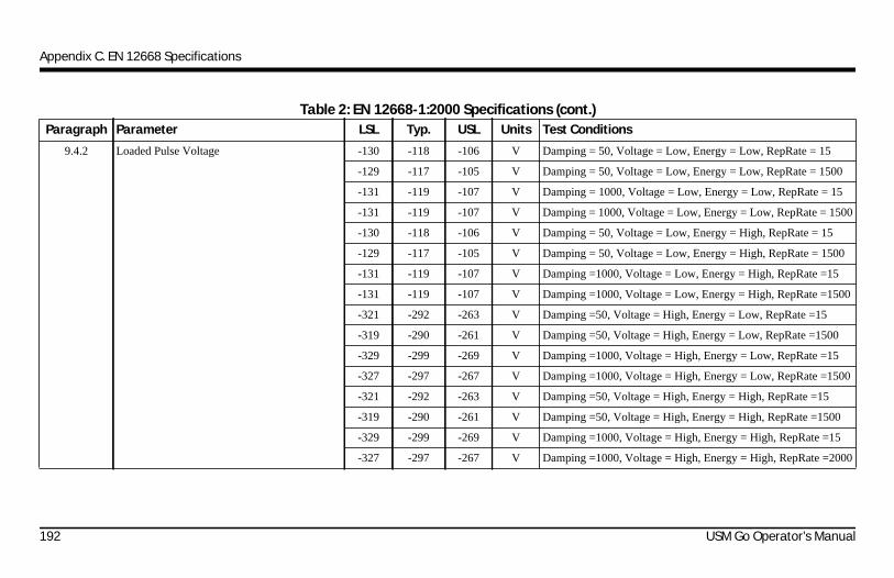
Appendix C. EN 12668 Specifications
Paragraph Parameter LSL Typ. USL Units Test Conditions
9.4.2 Loaded Pulse Voltage -130 -118 -106 V Damping = 50, Voltage = Low, Energy = Low, RepRate = 15
-129 -117 -105 V Damping = 50, Voltage = Low, Energy = Low, RepRate = 1500
-131 -119 -107 V Damping = 1000, Voltage = Low, Energy = Low, RepRate = 15
-131 -119 -107 V Damping = 1000, Voltage = Low, Energy = Low, RepRate = 1500
-130 -118 -106 V Damping = 50, Voltage = Low, Energy = High, RepRate = 15
-129 -117 -105 V Damping = 50, Voltage = Low, Energy = High, RepRate = 1500
-131 -119 -107 V Damping =1000, Voltage = Low, Energy = High, RepRate =15
-131 -119 -107 V Damping =1000, Voltage = Low, Energy = High, RepRate =1500
-321 -292 -263 V Damping =50, Voltage = High, Energy = Low, RepRate =15
-319 -290 -261 V Damping =50, Voltage = High, Energy = Low, RepRate =1500
-329 -299 -269 V Damping =1000, Voltage = High, Energy = Low, RepRate =15
-327 -297 -267 V Damping =1000, Voltage = High, Energy = Low, RepRate =1500
-321 -292 -263 V Damping =50, Voltage = High, Energy = High, RepRate =15
-319 -290 -261 V Damping =50, Voltage = High, Energy = High, RepRate =1500
-329 -299 -269 V Damping =1000, Voltage = High, Energy = High, RepRate =15
-327 -297 -267 V Damping =1000, Voltage = High, Energy = High, RepRate =2000
Table 2: EN 12668-1:2000 Specifications (cont.)
192 USM Go Operator’s Manual
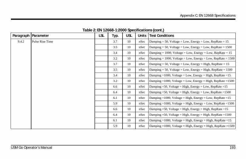
Appendix C. EN 12668 Specifications
Paragraph Parameter LSL Typ. USL Units Test Conditions
9.4.2 Pulse Rise Time 3.7 10 nSec Damping = 50, Voltage = Low, Energy = Low, RepRate = 15
3.5 10 nSec Damping = 50, Voltage = Low, Energy = Low, RepRate = 1500
3.4 10 nSec Damping = 1000, Voltage = Low, Energy = Low, RepRate = 15
3.2 10 nSec Damping = 1000, Voltage = Low, Energy = Low, RepRate = 1500
3.7 10 nSec Damping = 50, Voltage = Low, Energy = High, RepRate = 15
3.5 10 nSec Damping = 50, Voltage = Low, Energy = High, RepRate = 1500
3.4 10 nSec Damping =1000, Voltage = Low, Energy = High, RepRate =15
3.2 10 nSec Damping =1000, Voltage = Low, Energy = High, RepRate =1500
6.6 10 nSec Damping =50, Voltage = High, Energy = Low, RepRate =15
6.4 10 nSec Damping =50, Voltage = High, Energy = Low, RepRate =1500
6.1 10 nSec Damping =1000, Voltage = High, Energy = Low, RepRate =15
5.9 10 nSec Damping =1000, Voltage = High, Energy = Low, RepRate =1500
6.6 10 nSec Damping =50, Voltage = High, Energy = High, RepRate =15
6.4 10 nSec Damping =50, Voltage = High, Energy = High, RepRate =1500
6.1 10 nSec Damping =1000, Voltage = High, Energy = High, RepRate =15
5.9 10 nSec Damping =1000, Voltage = High, Energy = High, RepRate =1500
Table 2: EN 12668-1:2000 Specifications (cont.)
USM Go Operator’s Manual 193

Appendix C. EN 12668 Specifications
Paragraph Parameter LSL Typ. USL Units Test Conditions
9.4.2 Pulse Duration
SN starting with “0” in last four digits
45 50 55 nSec Damping = 50, Voltage = Low, Energy = Low, RepRate = 15
44 49 54 nSec Damping = 50, Voltage = Low, Energy = Low, RepRate = 1500
61 68 75 nSec Damping = 1000, Voltage = Low, Energy = Low, RepRate = 15
59 66 73 nSec Damping = 1000, Voltage = Low, Energy = Low, RepRate = 1500
109 121 133 nSec Damping = 50, Voltage = Low, Energy = High, RepRate = 15
109 121 133 nSec Damping = 50, Voltage = Low, Energy = High, RepRate = 1500
125 139 153 nSec Damping =1000, Voltage = Low, Energy = High, RepRate =15
125 139 153 nSec Damping =1000, Voltage = Low, Energy = High, RepRate =1500
29 32 35 nSec Damping =50, Voltage = High, Energy = Low, RepRate =15
27 30 33 nSec Damping =50, Voltage = High, Energy = Low, RepRate =1500
39 43 47 nSec Damping =1000, Voltage = High, Energy = Low, RepRate =15
37 41 45 nSec Damping =1000, Voltage = High, Energy = Low, RepRate =1500
94 104 124 nSec Damping =50, Voltage = High, Energy = High, RepRate =15
92 102 112 nSec Damping =50, Voltage = High, Energy = High, RepRate =1500
104 115 127 nSec Damping =1000, Voltage = High, Energy = High, RepRate =15
104 115 127 nSec Damping =1000, Voltage = High, Energy = High, RepRate =1500
Table 2: EN 12668-1:2000 Specifications (cont.)
194 USM Go Operator’s Manual

Appendix C. EN 12668 Specifications
Paragraph Parameter LSL Typ. USL Units Test Conditions
9.4.2 Pulse Duration
SN starting with “5” in last four digits
53 59 65 nSec Damping = 50, Voltage = Low, Energy = Low, RepRate = 15
52 58 64 nSec Damping = 50, Voltage = Low, Energy = Low, RepRate = 1500
72 81 89 nSec Damping = 1000, Voltage = Low, Energy = Low, RepRate = 15
71 79 87 nSec Damping = 1000, Voltage = Low, Energy = Low, RepRate = 1500
121 134 148 nSec Damping = 50, Voltage = Low, Energy = High, RepRate = 15
119 133 146 nSec Damping = 50, Voltage = Low, Energy = High, RepRate = 1500
141 157 172 nSec Damping =1000, Voltage = Low, Energy = High, RepRate =15
139 155 170 nSec Damping =1000, Voltage = Low, Energy = High, RepRate =1500
32 36 39 nSec Damping =50, Voltage = High, Energy = Low, RepRate =15
31 34 38 nSec Damping =50, Voltage = High, Energy = Low, RepRate =1500
43 47 52 nSec Damping =1000, Voltage = High, Energy = Low, RepRate =15
41 46 51 nSec Damping =1000, Voltage = High, Energy = Low, RepRate =1500
98 109 120 nSec Damping =50, Voltage = High, Energy = High, RepRate =15
97 107 118 nSec Damping =50, Voltage = High, Energy = High, RepRate =1500
109 121 133 nSec Damping =1000, Voltage = High, Energy = High, RepRate =15
109 120 132 nSec Damping =1000, Voltage = High, Energy = High, RepRate =1500
Table 2: EN 12668-1:2000 Specifications (cont.)
USM Go Operator’s Manual 195

Appendix C. EN 12668 Specifications
Paragraph Parameter LSL Typ. USL Units Test Conditions
9.4.2 Pulse Reverberation 0 4 V Damping = 50, Voltage = Low, Energy = Low, RepRate = 15
0 4 V Damping = 50, Voltage = Low, Energy = Low, RepRate = 1500
0 4 V Damping = 1000, Voltage = Low, Energy = Low, RepRate = 15
0 4 V Damping = 1000, Voltage = Low, Energy = Low, RepRate = 1500
0 4 V Damping = 50, Voltage = Low, Energy = High, RepRate = 15
0 4 V Damping = 50, Voltage = Low, Energy = High, RepRate = 1500
0 4 V Damping =1000, Voltage = Low, Energy = High, RepRate =15
0 4 V Damping =1000, Voltage = Low, Energy = High, RepRate =1500
0 4 V Damping =50, Voltage = High, Energy = Low, RepRate =15
0 4 V Damping =50, Voltage = High, Energy = Low, RepRate =1500
0 4 V Damping =1000, Voltage = High, Energy = Low, RepRate =15
0 4 V Damping =1000, Voltage = High, Energy = Low, RepRate =1500
0 4 V Damping =50, Voltage = High, Energy = High, RepRate =15
Table 2: EN 12668-1:2000 Specifications (cont.)
196 USM Go Operator’s Manual

Appendix C. EN 12668 Specifications
Paragraph Parameter LSL Typ. USL Units Test Conditions
9.4.2 Pulse Reverberation 0 4 V Damping =50, Voltage = High, Energy = High, RepRate =1500
0 4 V Damping =1000, Voltage = High, Energy = High, RepRate =15
0 4 V Damping =1000, Voltage = High, Energy = High, RepRate =1500
8.4.2 Crosstalk Pulser to Receiver 80 80 - dB
8.4.3 Dead Time After Transmitter Pulse 10 uSec Measured in worst case frequency setting
8.4.4 Dynamic Range 100 100 - dB Measured in worst case frequency setting
8.4.5 Receiver Input Impedance 160 Ohm Real Impedance at 4MHz
0 0.1 (Rmax gain - Rmin gain)/Rmax gain
40 Ohm Imaginary Impedance at 4MHz
358 pF Input Capacitance
0 0.15 (Cmax gain - Cmin gain)/Cmax gain
8.4.6 Distance Amplitude Correction -1.5 0 1.5 dB Maximum error between TCG curve and actual TCG correction
Table 2: EN 12668-1:2000 Specifications (cont.)
USM Go Operator’s Manual 197

Appendix C. EN 12668 Specifications
Paragraph Parameter LSL Typ. USL Units Test Conditions
9.5.2 Amplifier Frequency Response 2.05 2.16 2.27 MHz Center Frequency (Geometric Mean), 1-5 MHz selected
3.81 4.23 4.65 MHz Bandwidth, 1-5 MHz selected
1.86 1.96 2.06 MHz Center Frequency (Geometric Mean), 2 or 2.25 MHz selected
2.57 2.85 3.14 MHz Bandwidth, 2 or 2.25 MHz selected
4.18 4.4 4.62 MHz Center Frequency (Geometric Mean), 4 or 5 MHz selected
4.95 5.5 6.05 MHz Bandwidth, 4 or 5 MHz selected
8.76 9.22 9.68 MHz Center Frequency (Geometric Mean), 10 MHz selected
6.6 7.33 8.06 MHz Bandwidth, 10 MHz selected
13 13.68 14.36 MHz Center Frequency (Geometric Mean), 13 or 15 MHz selected
6.78 7.53 8.28 MHz Bandwidth, 13 or 15 MHz selected
4.5 4.74 5 MHz Center Frequency (Geometric Mean), BroadBand selected
17.41 19.34 21.27 MHz Bandwidth, BroadBand selected
Table 2: EN 12668-1:2000 Specifications (cont.)
198 USM Go Operator’s Manual

Appendix C. EN 12668 Specifications
Paragraph Parameter LSL Typ. USL Units Test Conditions
9.5.3 Equivalent Input Noise - 70 80 nV/sqrt Hz
1-5 MHz selected
70 80 nV/sqrt Hz
2 or 2.25 MHz selected
- 43 80 nV/sqrt Hz
4 or 5 MHz selected
- 34 80 nV/sqrt Hz
10 MHz selected
- 35 80 nV/sqrt Hz
13 or 15 MHz selected
- 38 80 nV/sqrt Hz
BroadBand selected
9.5.4 Accuracy of Calibrated Attenuator -1 0.7 1 dB Cumulative Error over 20dB Range
-2 0.7 2 dB Cumulative Error over 60dB Range
Table 2: EN 12668-1:2000 Specifications (cont.)
USM Go Operator’s Manual 199

Appendix C. EN 12668 Specifications
Paragraph Parameter LSL Typ. USL Units Test Conditions
9.5.5 Linearity of Vertical Display -2 0.6 2 %FSH 1, 2 or 2,25 MHz selected
-2 0.6 2 %FSH 4 or 5 MHz selected
-2 -0.9 2 %FSH 10 MHz selected
-2 -1.25 2 %FSH 13 or 15 MHz selected
-2 0.18 2 %FSH BroadBand selected
8.7.2 Linearity of Timebase - 0.03 0.5 %FSW
8.7.3 Digitization Sampling Error -5 -4 5 %FSH
Dimensions 11.1 CM Height
17.5 CM Width
5 CM Depth
<1 KG Weight (With Battery)
Table 2: EN 12668-1:2000 Specifications (cont.)
200 USM Go Operator’s Manual

Appendix C. EN 12668 Specifications
Paragraph Parameter LSL Typ. USL Units Test Conditions
8.7.3 Battery Life 6 Hr Instrument will automatically shut down when batteries are too low for reliable operation
Operating Temperature Range 0 - 55 DegC
Rectification Modes FW
HWP
HWN
RF
Pulse Repetition Frequency 15 2000 Hz Continuously Variable
Display Dimensions 12.6 CM Diagonal
800 x 480 Pixels
Number of Pixels to Display an A-Scan 512
A-Scan Graticule Major Divisions None, 5 or 10 Vertical and Horizontal, User selectable
A-Scan Graticule Minor Horizontal Divisions 50 Displayed along the baseline
A-Scan Graticule Minor Vertical Divisions 50 Displayed on the center vertical
Table 2: EN 12668-1:2000 Specifications (cont.)
USM Go Operator’s Manual 201
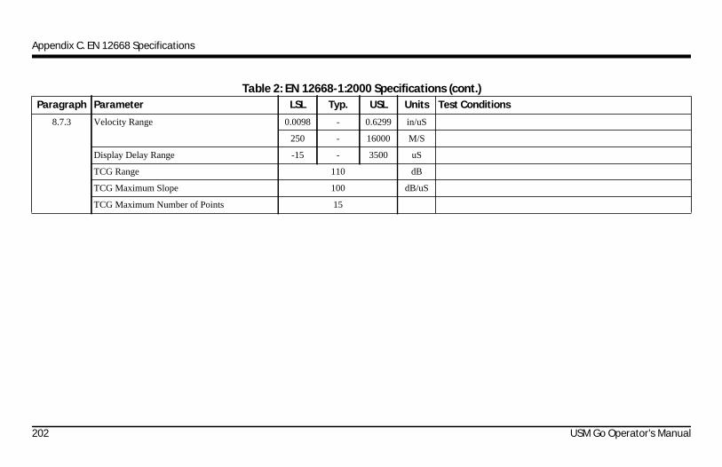
Appendix C. EN 12668 Specifications
Paragraph Parameter LSL Typ. USL Units Test Conditions
8.7.3 Velocity Range 0.0098 - 0.6299 in/uS
250 - 16000 M/S
Display Delay Range -15 - 3500 uS
TCG Range 110 dB
TCG Maximum Slope 100 dB/uS
TCG Maximum Number of Points 15
Table 2: EN 12668-1:2000 Specifications (cont.)
202 USM Go Operator’s Manual

Appendix C. EN 12668 Specifications
USM Go Operator’s Manual 203
Appendix C. EN 12668 Specifications
[no content intended for this page - proceed to next page]
204 USM Go Operator’s Manual

Index
AAcquire Menu
Description . . . . . . . . . . . . . . . . . . . . . . . . . . . . . . . . . . . . . . 21Diagram. . . . . . . . . . . . . . . . . . . . . . . . . . . . . . . . . . . . . . . . . 25
Acquire ModeAccessing the Menu . . . . . . . . . . . . . . . . . . . . . . . . . . . . . . . 12Display . . . . . . . . . . . . . . . . . . . . . . . . . . . . . . . . . . . . . . . . . 10
AlarmsCalibration Reminder . . . . . . . . . . . . . . . . . . . . . . . . . . . . . . 73Defining Logic . . . . . . . . . . . . . . . . . . . . . . . . . . . . . . . . . . . 85Indicator Light, Assigning . . . . . . . . . . . . . . . . . . . . . . . . . . 86
Amplitude Readings in dB REF Mode . . . . . . . . . . . . . . . . . . . 125Angle Beam Probe Parameters . . . . . . . . . . . . . . . . . . . . . . . . . . 88
A-ScanFlank/Peak of Signal . . . . . . . . . . . . . . . . . . . . . . . . . . . . . . . 83Freezing . . . . . . . . . . . . . . . . . . . . . . . . . . . . . . . . . . . . . . . . . 99Full-Screen Display . . . . . . . . . . . . . . . . . . . . . . . . . . . . . . . . 11Previewing Saved DR File Image . . . . . . . . . . . . . . . . . . . . 166Saving in Report . . . . . . . . . . . . . . . . . . . . . . . . . . . . . . . . . 155Saving to DR File . . . . . . . . . . . . . . . . . . . . . . . . . . . . . . . . 165Selecting a Rectification Mode . . . . . . . . . . . . . . . . . . . . . . . 61Setting the Color . . . . . . . . . . . . . . . . . . . . . . . . . . . . . . . . . . 45Setting the Display Delay . . . . . . . . . . . . . . . . . . . . . . . . . . . 67Setting the Range. . . . . . . . . . . . . . . . . . . . . . . . . . . . . . . . . . 65Setting the Reject Level. . . . . . . . . . . . . . . . . . . . . . . . . . . . . 64
Autocal Procedures . . . . . . . . . . . . . . . . . . . . . . . . . . . . . . . . . . . . 69Automatic Gate Threshold (AGT) . . . . . . . . . . . . . . . . . . . . . . . . 82AWS D1.1 Mode
Description. . . . . . . . . . . . . . . . . . . . . . . . . . . . . . . . . . . . . . 126Setup . . . . . . . . . . . . . . . . . . . . . . . . . . . . . . . . . . . . . . . . . . 127
USM Go Operator’s Manual 193
Index
BBatteries
Disposal. . . . . . . . . . . . . . . . . . . . . . . . . . . . . . . . . . . . . . . . 189Installing . . . . . . . . . . . . . . . . . . . . . . . . . . . . . . . . . . . . . . . . . 3Level Indicator . . . . . . . . . . . . . . . . . . . . . . . . . . . . . . . . . . . . 3Safety Information . . . . . . . . . . . . . . . . . . . . . . . . . . . . . . . . xiiiSpecifications . . . . . . . . . . . . . . . . . . . . . . . . . . . . . . . . . . . 182
Brightness, Setting . . . . . . . . . . . . . . . . . . . . . . . . . . . . . . . . . . . . 46C
Calibration . . . . . . . . . . . . . . . . . . . . . . . . . . . . . . . . . . . . . . . . . . 68Checking Results . . . . . . . . . . . . . . . . . . . . . . . . . . . . . . . . . 72Preliminary Checklist . . . . . . . . . . . . . . . . . . . . . . . . . . . . . . 68Reminder Alarm . . . . . . . . . . . . . . . . . . . . . . . . . . . . . . . . . . 73Using Autocal . . . . . . . . . . . . . . . . . . . . . . . . . . . . . . . . . . . . 69
Case, Rear and Side Views . . . . . . . . . . . . . . . . . . . . . . . . . . . . . . 2Color
Setting for A-Scan. . . . . . . . . . . . . . . . . . . . . . . . . . . . . . . . . 45Setting for Display . . . . . . . . . . . . . . . . . . . . . . . . . . . . . . . . 43Setting for Indicating Leg . . . . . . . . . . . . . . . . . . . . . . . . . . . 90
Config1 Menu Diagram . . . . . . . . . . . . . . . . . . . . . . . . . . . . . . . . 25
ConnectorsI/O . . . . . . . . . . . . . . . . . . . . . . . . . . . . . . . . . . . . . . . . . . . . . 17Specifications. . . . . . . . . . . . . . . . . . . . . . . . . . . . . . . . . . . . 178USB . . . . . . . . . . . . . . . . . . . . . . . . . . . . . . . . . . . . . . . . . . . . 16
COPY Function. . . . . . . . . . . . . . . . . . . . . . . . . . . . . . . . . . . . . . 156Creating
Data Recorder Files . . . . . . . . . . . . . . . . . . . . . . . . . . . . . . . 162Memo. . . . . . . . . . . . . . . . . . . . . . . . . . . . . . . . . . . . . . 150, 153Report . . . . . . . . . . . . . . . . . . . . . . . . . . . . . . . . . . . . . . . . . 155
Customer Support Centers . . . . . . . . . . . . . . . . . . . . . . . . . . . . . . . 2D
DAC ModeDeleting a DAC Curve. . . . . . . . . . . . . . . . . . . . . . . . . . . . . 113Recording the DAC Curve. . . . . . . . . . . . . . . . . . . . . . . . . . 105Using . . . . . . . . . . . . . . . . . . . . . . . . . . . . . . . . . . . . . . . . . . 104Working With . . . . . . . . . . . . . . . . . . . . . . . . . . . . . . . . . . . 107
194 USM Go Operator’s Manual

Index
DAC/TCG ModeAdding Offsets . . . . . . . . . . . . . . . . . . . . . . . . . . . . . . . . . . 110Adding/Deleting Reference Points . . . . . . . . . . . . . . . . . . . 112Description . . . . . . . . . . . . . . . . . . . . . . . . . . . . . . . . . . . . . 103Setting Transfer Correction. . . . . . . . . . . . . . . . . . . . . . . . . 111
Damping Level, Probe . . . . . . . . . . . . . . . . . . . . . . . . . . . . . . . . . 53Data Recorder Files
Creating. . . . . . . . . . . . . . . . . . . . . . . . . . . . . . . . . . . . . . . . 162Menu . . . . . . . . . . . . . . . . . . . . . . . . . . . . . . . . . . . . . . . . . . 159Naming . . . . . . . . . . . . . . . . . . . . . . . . . . . . . . . . . . . . . . . . 160Using . . . . . . . . . . . . . . . . . . . . . . . . . . . . . . . . . . . . . . . . . . 165Viewing. . . . . . . . . . . . . . . . . . . . . . . . . . . . . . . . . . . . . . . . 163
Data Set FilesDeleting. . . . . . . . . . . . . . . . . . . . . . . . . . . . . . . . . . . . . . . . 148Editing. . . . . . . . . . . . . . . . . . . . . . . . . . . . . . . . . . . . . . . . . 149Recalling . . . . . . . . . . . . . . . . . . . . . . . . . . . . . . . . . . . . . . . 147Storing. . . . . . . . . . . . . . . . . . . . . . . . . . . . . . . . . . . . . . . . . 145Working With . . . . . . . . . . . . . . . . . . . . . . . . . . . . . . . . . . . 145
Date of Publication. . . . . . . . . . . . . . . . . . . . . . . . . . . . . . . . . . . . . . iDate, Setting. . . . . . . . . . . . . . . . . . . . . . . . . . . . . . . . . . . . . . . . . 29
dB REF ModeAmplitude Readings Available . . . . . . . . . . . . . . . . . . . . . . 125Description. . . . . . . . . . . . . . . . . . . . . . . . . . . . . . . . . . . . . . 124
dB Step Gain Adjustment . . . . . . . . . . . . . . . . . . . . . . . . . . . . . . . 95Decimal Convention, Setting . . . . . . . . . . . . . . . . . . . . . . . . . . . . 28Delay, Setting for Display. . . . . . . . . . . . . . . . . . . . . . . . . . . . . . . 67Deleting Data Set Files . . . . . . . . . . . . . . . . . . . . . . . . . . . . . . . . 148DGS Mode
Description. . . . . . . . . . . . . . . . . . . . . . . . . . . . . . . . . . . . . . 113Display & Adjust Curve . . . . . . . . . . . . . . . . . . . . . . . . . . . 121Evaluating Results . . . . . . . . . . . . . . . . . . . . . . . . . . . . . . . . 122Influencing Variables. . . . . . . . . . . . . . . . . . . . . . . . . . . . . . 115Locks & Error Messages . . . . . . . . . . . . . . . . . . . . . . . . . . . 123Recording the Reference Echo . . . . . . . . . . . . . . . . . . . . . . 119Specifying a Probe. . . . . . . . . . . . . . . . . . . . . . . . . . . . . . . . 116Validity . . . . . . . . . . . . . . . . . . . . . . . . . . . . . . . . . . . . . . . . 123
USM Go Operator’s Manual 195

Index
DisplayAppearance . . . . . . . . . . . . . . . . . . . . . . . . . . . . . . . . . . . . . . 43Freezing. . . . . . . . . . . . . . . . . . . . . . . . . . . . . . . . . . . . . . . . . 99Measured Results Configuration. . . . . . . . . . . . . . . . . . . . . . 93Measured Results Parameters . . . . . . . . . . . . . . . . . . . . . . . . 90Screen Features . . . . . . . . . . . . . . . . . . . . . . . . . . . . . . . . . . . 20Screen Icons . . . . . . . . . . . . . . . . . . . . . . . . . . . . . . . . . . . . . 19Selecting the Grid . . . . . . . . . . . . . . . . . . . . . . . . . . . . . . . . . 44Setting the A-Scan Delay . . . . . . . . . . . . . . . . . . . . . . . . . . . 67Setting the Brightness . . . . . . . . . . . . . . . . . . . . . . . . . . . . . . 46Setting the Color . . . . . . . . . . . . . . . . . . . . . . . . . . . . . . . . . . 43Specifications . . . . . . . . . . . . . . . . . . . . . . . . . . . . . . . . . . . 177Using . . . . . . . . . . . . . . . . . . . . . . . . . . . . . . . . . . . . . . . . . . . 10
DisposalBatteries . . . . . . . . . . . . . . . . . . . . . . . . . . . . . . . . . . . . . . . 189Electronic Waste . . . . . . . . . . . . . . . . . . . . . . . . . . . . . . . . . 188
EEditing Data Set Files . . . . . . . . . . . . . . . . . . . . . . . . . . . . . . . . 149EN 12668 Specifications . . . . . . . . . . . . . . . . . . . . . . . . . . . . . . 191Energy, Setting for Pulser . . . . . . . . . . . . . . . . . . . . . . . . . . . . . . 59
Environmental Specifications . . . . . . . . . . . . . . . . . . . . . . . . . . . 182Error Messages in DGS Mode . . . . . . . . . . . . . . . . . . . . . . . . . . 123Evaluation Mode
AWS D1.1 . . . . . . . . . . . . . . . . . . . . . . . . . . . . . . . . . . . . . . 126DAC/TCG . . . . . . . . . . . . . . . . . . . . . . . . . . . . . . . . . . . . . . 103dB REF . . . . . . . . . . . . . . . . . . . . . . . . . . . . . . . . . . . . . . . . 124DGS . . . . . . . . . . . . . . . . . . . . . . . . . . . . . . . . . . . . . . . . . . . 113JISDAC . . . . . . . . . . . . . . . . . . . . . . . . . . . . . . . . . . . . . . . . 128Options Diagram . . . . . . . . . . . . . . . . . . . . . . . . . . . . . . . . . . 23TCG . . . . . . . . . . . . . . . . . . . . . . . . . . . . . . . . . . . . . . . . . . . 108
FFast Report . . . . . . . . . . . . . . . . . . . . . . . . . . . . . . . . . . . . . . . . . 157Features, Display Screen. . . . . . . . . . . . . . . . . . . . . . . . . . . . . . . . 20FILES Menu . . . . . . . . . . . . . . . . . . . . . . . . . . . . . . . . . . . . . . . . 144Flank, A-Scan Signal . . . . . . . . . . . . . . . . . . . . . . . . . . . . . . . . . . 83Freezing the A-Scan Display . . . . . . . . . . . . . . . . . . . . . . . . . . . . 99Frequency, Probe . . . . . . . . . . . . . . . . . . . . . . . . . . . . . . . . . . . . . 52Full-Screen A-Scan Display . . . . . . . . . . . . . . . . . . . . . . . . . . . . . 11
196 USM Go Operator’s Manual

Index
Function ToggleCOPY Function. . . . . . . . . . . . . . . . . . . . . . . . . . . . . . . . . . 156Data Recorder Files. . . . . . . . . . . . . . . . . . . . . . . . . . . . . . . 165Defining the Actions . . . . . . . . . . . . . . . . . . . . . . . . . . . . . . . 47Description . . . . . . . . . . . . . . . . . . . . . . . . . . . . . . . . . . . . . . . 7Magnify Gate . . . . . . . . . . . . . . . . . . . . . . . . . . . . . . . . . . . . 87
GGain
Changing the dB Step Value. . . . . . . . . . . . . . . . . . . . . . . . . 95Setting . . . . . . . . . . . . . . . . . . . . . . . . . . . . . . . . . . . . . . . . . . 95User-Defined Step Value . . . . . . . . . . . . . . . . . . . . . . . . . . . 96
Gain ToggleDescription . . . . . . . . . . . . . . . . . . . . . . . . . . . . . . . . . . . . . . . 7Locking . . . . . . . . . . . . . . . . . . . . . . . . . . . . . . . . . . . . . . . . . 94
Gate Asee Gates
Gate Alarmssee Alarms
Gate Bsee Gates
GatesAdjusting in Full-Screen Mode . . . . . . . . . . . . . . . . . . . . . . . 11Adjusting the Width. . . . . . . . . . . . . . . . . . . . . . . . . . . . . . . . 81Automatic Threshold (AGT) . . . . . . . . . . . . . . . . . . . . . . . . . 82Configuring . . . . . . . . . . . . . . . . . . . . . . . . . . . . . . . . . . . . . . 77Magnify . . . . . . . . . . . . . . . . . . . . . . . . . . . . . . . . . . . . . . . . . 87Positioning . . . . . . . . . . . . . . . . . . . . . . . . . . . . . . . . . . . . . . . 79Setting the Starting Point . . . . . . . . . . . . . . . . . . . . . . . . . . . . 80Setting the Threshold. . . . . . . . . . . . . . . . . . . . . . . . . . . . . . . 82Specifications. . . . . . . . . . . . . . . . . . . . . . . . . . . . . . . . . . . . 181
Grid, Selecting . . . . . . . . . . . . . . . . . . . . . . . . . . . . . . . . . . . . . . . 44H
HDR IN REPORT Function . . . . . . . . . . . . . . . . . . . . . . . . . . . . 155Header
Creating for Report . . . . . . . . . . . . . . . . . . . . . . . . . . . . . . . 153Including in Report . . . . . . . . . . . . . . . . . . . . . . . . . . . . . . . 154
II/O Connector . . . . . . . . . . . . . . . . . . . . . . . . . . . . . . . . . . . . . . . . 17
USM Go Operator’s Manual 197

Index
IconsBattery Level. . . . . . . . . . . . . . . . . . . . . . . . . . . . . . . . . . . . . . 3Complete Set. . . . . . . . . . . . . . . . . . . . . . . . . . . . . . . . . . . . . 19
IMAGE IN REPORT Function . . . . . . . . . . . . . . . . . . . . . . . . . 155Indicating Leg Color . . . . . . . . . . . . . . . . . . . . . . . . . . . . . . . . . . 90Indicator Light, Alarms . . . . . . . . . . . . . . . . . . . . . . . . . . . . . . . . 86Initial Setup . . . . . . . . . . . . . . . . . . . . . . . . . . . . . . . . . . . . . . . . . 24
JJFlank, A-Scan Signal . . . . . . . . . . . . . . . . . . . . . . . . . . . . . . . . . 83JISDAC Mode
Defining a Bold Line . . . . . . . . . . . . . . . . . . . . . . . . . . . . . 132Deleting a JISDAC Curve. . . . . . . . . . . . . . . . . . . . . . . . . . 133Description . . . . . . . . . . . . . . . . . . . . . . . . . . . . . . . . . . . . . 128Interpreting Lines and Classes . . . . . . . . . . . . . . . . . . . . . . 131Recording the JISDAC Curve. . . . . . . . . . . . . . . . . . . . . . . 129Setting the Transfer Correction. . . . . . . . . . . . . . . . . . . . . . 132Working With . . . . . . . . . . . . . . . . . . . . . . . . . . . . . . . . . . . 130
JoystickDescription. . . . . . . . . . . . . . . . . . . . . . . . . . . . . . . . . . . . . . . . 7Joy Control parameter . . . . . . . . . . . . . . . . . . . . . . . . . . . . . . 11Locking . . . . . . . . . . . . . . . . . . . . . . . . . . . . . . . . . . . . . . . . . 94Operation . . . . . . . . . . . . . . . . . . . . . . . . . . . . . . . . . . . . . . . . . 8
KKeypad
Components . . . . . . . . . . . . . . . . . . . . . . . . . . . . . . . . . . . . . 5, 7Using . . . . . . . . . . . . . . . . . . . . . . . . . . . . . . . . . . . . . . . . . . . . 4
LLanguage, Setting . . . . . . . . . . . . . . . . . . . . . . . . . . . . . . . . . . . . . 26Live Video Recording. . . . . . . . . . . . . . . . . . . . . . . . . . . . . . . . . 169Locking the Gain Toggle or Joystick . . . . . . . . . . . . . . . . . . . . . . 94Locks in DGS Mode . . . . . . . . . . . . . . . . . . . . . . . . . . . . . . . . . . 123
MMagnify Gate . . . . . . . . . . . . . . . . . . . . . . . . . . . . . . . . . . . . . . . . 87Measured Results
Available Parameters . . . . . . . . . . . . . . . . . . . . . . . . . . . . . . . 90Configuration of Display . . . . . . . . . . . . . . . . . . . . . . . . . . . . 93Evaluating in DGS Mode. . . . . . . . . . . . . . . . . . . . . . . . . . . 122
198 USM Go Operator’s Manual

Index
MemoCreating. . . . . . . . . . . . . . . . . . . . . . . . . . . . . . . . . . . . 150, 153Including in Report . . . . . . . . . . . . . . . . . . . . . . . . . . . . . . . 152
MEMO IN REPORT Function . . . . . . . . . . . . . . . . . . . . . . . . . 155Menu System
Acquire Menu . . . . . . . . . . . . . . . . . . . . . . . . . . . . . . . . . . . . 21Diagram. . . . . . . . . . . . . . . . . . . . . . . . . . . . . . . . . . . . . . . . . 22Evaluation Mode Options . . . . . . . . . . . . . . . . . . . . . . . . . . . 23Setup Menu . . . . . . . . . . . . . . . . . . . . . . . . . . . . . . . . . . . . . . 21
Multi-Key Functions . . . . . . . . . . . . . . . . . . . . . . . . . . . . . . . . . . . 9N
Naming Data Recorder Files . . . . . . . . . . . . . . . . . . . . . . . . . . . 160O
Offsets, Adding to DAC/TCG Curve. . . . . . . . . . . . . . . . . . . . . 110Operator Training. . . . . . . . . . . . . . . . . . . . . . . . . . . . . . . . . . . . . xvOptions, Specifications . . . . . . . . . . . . . . . . . . . . . . . . . . . . . . . 184Orientation
Setting . . . . . . . . . . . . . . . . . . . . . . . . . . . . . . . . . . . . . . . . . . 32P
PARAM IN REPORT Function. . . . . . . . . . . . . . . . . . . . . . . . . 155
Part Number, Manual . . . . . . . . . . . . . . . . . . . . . . . . . . . . . . . . . . . iPeak, A-Scan Signal . . . . . . . . . . . . . . . . . . . . . . . . . . . . . . . . . . . 83Phantom PRF Feature . . . . . . . . . . . . . . . . . . . . . . . . . . . . . . . . . . 60Positioning the Gates . . . . . . . . . . . . . . . . . . . . . . . . . . . . . . . . . . 79Power
Battery Pack. . . . . . . . . . . . . . . . . . . . . . . . . . . . . . . . . . . . . . . 3External Adapter . . . . . . . . . . . . . . . . . . . . . . . . . . . . . . . . . . . 3
Powering ON and OFF . . . . . . . . . . . . . . . . . . . . . . . . . . . . . . . . . . 4Previewing Saved A-Scan Image . . . . . . . . . . . . . . . . . . . . . . . . 166PRF
Modes Available . . . . . . . . . . . . . . . . . . . . . . . . . . . . . . . . . . 54Selecting the Pulser Energy (Spike Mode) . . . . . . . . . . . . . . 59Selecting the Pulser Type . . . . . . . . . . . . . . . . . . . . . . . . . . . 56Selecting the Pulser Width (Square Wave Mode) . . . . . . . . . 57Setting the Pulser Frequency . . . . . . . . . . . . . . . . . . . . . . . . . 54Setting the Pulser Voltage . . . . . . . . . . . . . . . . . . . . . . . . . . . 55Using the Phantom Feature . . . . . . . . . . . . . . . . . . . . . . . . . . 60
USM Go Operator’s Manual 199

Index
ProbeAngle Beam Parameters . . . . . . . . . . . . . . . . . . . . . . . . . . . . 88Changing the Damping Level . . . . . . . . . . . . . . . . . . . . . . . . 53Configuring . . . . . . . . . . . . . . . . . . . . . . . . . . . . . . . . . . . . . . 50Connecting . . . . . . . . . . . . . . . . . . . . . . . . . . . . . . . . . . . . . . 49Selecting the Type. . . . . . . . . . . . . . . . . . . . . . . . . . . . . . . . . 50Specifying for DGS Mode . . . . . . . . . . . . . . . . . . . . . . . . . 116Specifying the Frequency . . . . . . . . . . . . . . . . . . . . . . . . . . . 52
Protection Specifications . . . . . . . . . . . . . . . . . . . . . . . . . . . . . . 183Pulser
Frequency Setting . . . . . . . . . . . . . . . . . . . . . . . . . . . . . . . . . 54Selecting the Energy (Spike Mode) . . . . . . . . . . . . . . . . . . . 59Selecting the Type. . . . . . . . . . . . . . . . . . . . . . . . . . . . . . . . . 56Selecting the Width (Square Wave Mode) . . . . . . . . . . . . . . 57Setting the Voltage . . . . . . . . . . . . . . . . . . . . . . . . . . . . . . . . 55Specifications . . . . . . . . . . . . . . . . . . . . . . . . . . . . . . . . . . . 179
Pulser Repetition Frequencysee PRF
RRange, Setting for A-Scan . . . . . . . . . . . . . . . . . . . . . . . . . . . . . . 65
Recalling Data Set Files . . . . . . . . . . . . . . . . . . . . . . . . . . . . . . . 147Receiver Specifications. . . . . . . . . . . . . . . . . . . . . . . . . . . . . . . . 180Record Mode. . . . . . . . . . . . . . . . . . . . . . . . . . . . . . . . . . . . . . . . 172Rectification Mode, Selecting. . . . . . . . . . . . . . . . . . . . . . . . . . . . 61Reference Echo, Recording for DGS Curve . . . . . . . . . . . . . . . . 119Reference Points, Adding/Deleting for DAC/TCG . . . . . . . . . . 112Reject Level, Setting. . . . . . . . . . . . . . . . . . . . . . . . . . . . . . . . . . . 64Replay Mode. . . . . . . . . . . . . . . . . . . . . . . . . . . . . . . . . . . . . . . . 174Report
Creating . . . . . . . . . . . . . . . . . . . . . . . . . . . . . . . . . . . . . . . . 155Creating Header . . . . . . . . . . . . . . . . . . . . . . . . . . . . . . . . . . 153Fast Report. . . . . . . . . . . . . . . . . . . . . . . . . . . . . . . . . . . . . . 157Including Header . . . . . . . . . . . . . . . . . . . . . . . . . . . . . . . . . 154Including Memo. . . . . . . . . . . . . . . . . . . . . . . . . . . . . . . . . . 152Storing . . . . . . . . . . . . . . . . . . . . . . . . . . . . . . . . . . . . . . . . . 156
SSafety Information . . . . . . . . . . . . . . . . . . . . . . . . . . . . . . . . . . . xiii
200 USM Go Operator’s Manual

Index
Setup ModeAccessing the Menu . . . . . . . . . . . . . . . . . . . . . . . . . . . . . . . 13Display . . . . . . . . . . . . . . . . . . . . . . . . . . . . . . . . . . . . . . . . . 10Menu Description . . . . . . . . . . . . . . . . . . . . . . . . . . . . . . . . . 21
Setup, Initial . . . . . . . . . . . . . . . . . . . . . . . . . . . . . . . . . . . . . . . . . 24Software Upgrades . . . . . . . . . . . . . . . . . . . . . . . . . . . . . . . . . . . . 74Specifications
Connectors . . . . . . . . . . . . . . . . . . . . . . . . . . . . . . . . . . . . . 178Display . . . . . . . . . . . . . . . . . . . . . . . . . . . . . . . . . . . . . . . . 177EN 12668 . . . . . . . . . . . . . . . . . . . . . . . . . . . . . . . . . . . . . . 191Environmental. . . . . . . . . . . . . . . . . . . . . . . . . . . . . . . . . . . 182Gates . . . . . . . . . . . . . . . . . . . . . . . . . . . . . . . . . . . . . . . . . . 181Protection . . . . . . . . . . . . . . . . . . . . . . . . . . . . . . . . . . . . . . 183Pulser. . . . . . . . . . . . . . . . . . . . . . . . . . . . . . . . . . . . . . . . . . 179Receiver . . . . . . . . . . . . . . . . . . . . . . . . . . . . . . . . . . . . . . . 180USM Go . . . . . . . . . . . . . . . . . . . . . . . . . . . . . . . . . . . . . . . 177USM Go Options . . . . . . . . . . . . . . . . . . . . . . . . . . . . . . . . 184
Spike Mode, Pulser Type . . . . . . . . . . . . . . . . . . . . . . . . . . . . . . . 56Square Wave Mode, Pulser Type. . . . . . . . . . . . . . . . . . . . . . . . . 56Starting Point, Setting for Gates . . . . . . . . . . . . . . . . . . . . . . . . . 80
StoringData Set Files. . . . . . . . . . . . . . . . . . . . . . . . . . . . . . . . . . . . 145Report . . . . . . . . . . . . . . . . . . . . . . . . . . . . . . . . . . . . . . . . . 156
TTCG Mode
Deleting Reference Points . . . . . . . . . . . . . . . . . . . . . . . . . . 113Generating the Reference Curve . . . . . . . . . . . . . . . . . . . . . 108Using . . . . . . . . . . . . . . . . . . . . . . . . . . . . . . . . . . . . . . . . . . 108Working With . . . . . . . . . . . . . . . . . . . . . . . . . . . . . . . . . . . 109
Test ObjectMaterial Effects . . . . . . . . . . . . . . . . . . . . . . . . . . . . . . . . . . xviTemperature Effects. . . . . . . . . . . . . . . . . . . . . . . . . . . . . . . xvi
Threshold, Setting for Gates . . . . . . . . . . . . . . . . . . . . . . . . . . . . . 82Time, Setting. . . . . . . . . . . . . . . . . . . . . . . . . . . . . . . . . . . . . . . . . 29TOF-Detection Method, Selecting . . . . . . . . . . . . . . . . . . . . . . . . 83Transfer Correction
Setting for DAC/TCG Mode . . . . . . . . . . . . . . . . . . . . . . . . 111Setting for JISDAC Mode . . . . . . . . . . . . . . . . . . . . . . . . . . 132
UUltrasonic Testing Guidelines. . . . . . . . . . . . . . . . . . . . . . . . . . . xiv
USM Go Operator’s Manual 201

Index
Units of Measure, Setting. . . . . . . . . . . . . . . . . . . . . . . . . . . . . . . 27Upgrades, Instrument Software . . . . . . . . . . . . . . . . . . . . . . . . . . 74USB Connector . . . . . . . . . . . . . . . . . . . . . . . . . . . . . . . . . . . . . . 16Using Data Recorder Files . . . . . . . . . . . . . . . . . . . . . . . . . . . . . 165
VValidity of DGS Mode. . . . . . . . . . . . . . . . . . . . . . . . . . . . . . . . 123Video Record File . . . . . . . . . . . . . . . . . . . . . . . . . . . . . . . 172, 174Viewing
Data Recorder Files. . . . . . . . . . . . . . . . . . . . . . . . . . . . . . . 163W
Warranty. . . . . . . . . . . . . . . . . . . . . . . . . . . . . . . . . . . . . . . . . . . xviiWaste Disposal
Batteries . . . . . . . . . . . . . . . . . . . . . . . . . . . . . . . . . . . . . . . 189Electronic Equipment . . . . . . . . . . . . . . . . . . . . . . . . . . . . . 188
WEEE Directive. . . . . . . . . . . . . . . . . . . . . . . . . . . . . . . . . . . . . 188Width, Adjusting for Gates . . . . . . . . . . . . . . . . . . . . . . . . . . . . . 81
202 USM Go Operator’s Manual


Customer Support Centers
North & South America50 Industrial Park RoadLewistown, PA 17044U.S.A.Tel: 866 243 2638 (toll-free)
717 242 0327
United Kingdom/Ireland892 Charter Avenue CanleyCoventry CV4 8AFEnglandTel: +44 845 130 3925
France68, Chemin des OrmeauxLimonest 69760FranceTel: +33 47 217 9216
GermanyRobert Bosch Str.50354 HürthGermanyTel: +49 2233 601 0
SpainSan Maximo,31, Planta 4A, Nave 6Madrid 28041SpainTel: +34 195 005 990
China5F, Building 1, No. 1 Huatuo Road,Zhangjiang High-Tech Park,Shanghai 201203ChinaTel: +86 800 915 9966 (toll-free)
+86 (0)21 3877 7888
Japan7F Medie Corp Bldg. 82-4-14-Kichijoji Honcho,Musashino-shiTokyo 180-0004JapanTel: +81 442 67 7067
E-mail: [email protected]
www.ge-mcs.com
©2011 General Electric Company. All rights reserved.Technical content subject to change without notice.P/N 1259801 Rev 5