GE Grid Solutions Manufacturer recomended Tightening-Torque to apply to customer terminal block: 9...
40
GE Grid Solutions Instruction Manual Product version: GPRP00000208x GE publication code: 1601-0410-A1 (GEK-130861) Multilin DGPR 1601-0410-A1
Transcript of GE Grid Solutions Manufacturer recomended Tightening-Torque to apply to customer terminal block: 9...

GEGrid Solutions
Instruction ManualProduct version: GPRP00000208x
GE publication code: 1601-0410-A1 (GEK-130861)
Multilin DGPR
1601-0410-A1

Copyright © 2016 GE Multilin Inc. All rights reserved.
Multilin DGPR Instruction Manual for version GPRP00000208x.
DGPR, EnerVista, Multilin, and GE Multilin are trademarks or registered trademarks of GE Multilin Inc.
The contents of this manual are the property of GE Multilin Inc. This documentation is furnished on license and may not be reproduced in whole or in part without the permission of GE Multilin. The content of this manual is for informational use only and is subject to change without notice.
Part number: 1601-0410-A1 (February 2016)

MULTILIN DGPR – INSTRUCTION MANUAL iii
DGPR
Table of contents
1 INTRODUCTION Safety symbols and definitions....................................................................................1For further assistance ...................................................................................................1
2 PRODUCT DESCRIPTION
Product description........................................................................................................3Order codes .....................................................................................................................4Specifications ..................................................................................................................5
3 INSTALLATION Unpack and inspect .......................................................................................................7Panel dimensions ...........................................................................................................9
Front panel ........................................................................................................................................................9Side layout .........................................................................................................................................................9Rear terminal layout .................................................................................................................................. 10
Rear panel......................................................................................................................11Wiring diagrams...........................................................................................................11
Difference between CT connections of DGP and DGPR ............................................................ 15CT inputs system side................................................................................................................................ 16CT inputs neutral side................................................................................................................................ 17Voltage inputs ...............................................................................................................................................17Digital inputs and outputs....................................................................................................................... 18Inputs ................................................................................................................................................................ 18Outputs............................................................................................................................................................. 18Test switches ................................................................................................................................................. 19
Install hardware ...........................................................................................................20Mount the unit...............................................................................................................................................20Connect the wires ....................................................................................................................................... 24Connect the power supply ...................................................................................................................... 25
Activate G60 relay........................................................................................................26Install software.............................................................................................................26Connect G60 relay........................................................................................................27
Connect using RS232 port....................................................................................................................... 27Connect using Ethernet port .................................................................................................................. 28Connect using RS485 port....................................................................................................................... 29
IRIG-B..............................................................................................................................29

iv MULTILIN DGPR – INSTRUCTION MANUAL
TABLE OF CONTENTS
4 MAINTENANCE Repairs............................................................................................................................31
A MISCELLANEOUS Warranty....................................................................................................................... 33Revision history ........................................................................................................... 33
INDEX

MULTILIN DGPR – INSTRUCTION MANUAL 1
DGPR
Chapter 1: Introduction
Introduction
This chapter outlines safety and technical support information.
Safety symbols and definitionsBefore attempting to install or use the device, review all safety indicators in this document to help prevent injury, equipment damage, or downtime.
The following safety and equipment symbols are used in this document.
Indicates a hazardous situation which, if not avoided, will result in death or serious injury.
Indicates a hazardous situation which, if not avoided, could result in death or serious injury.
Indicates a hazardous situation which, if not avoided, could result in minor or moderate injury.
Indicates practices not related to personal injury.
For further assistanceFor product support, contact the information and call center as follows:
GE Grid Solutions650 Markland StreetMarkham, OntarioCanada L6C 0M1Worldwide telephone: +1 905 927 7070Europe/Middle East/Africa telephone: +34 94 485 88 54North America toll-free: 1 800 547 8629Fax: +1 905 927 5098Worldwide e-mail: [email protected]

2 MULTILIN DGPR – INSTRUCTION MANUAL
FOR FURTHER ASSISTANCE CHAPTER 1: INTRODUCTION
Europe e-mail: [email protected]: http://www.gegridsolutions.com/multilin

MULTILIN DGPR – INSTRUCTION MANUAL 3
DGPR
Chapter 2: Product description
Product description
This chapter outlines the product, order codes, and specifications.
Product descriptionThe Multilin DGPR is a pre-designed retrofit solution for the Digital Generator Protection (DGP) Relay. The DGPR is a one-to-one replacement of a DGP relay and includes a G60 Generator Protection System, which is part of the GE Universal Relay (UR) family of products.
The DGPR is a microprocessor-based digital relay system that uses waveform sampling of current and voltage inputs to provide protection, control, and monitoring of generators. It can be used with any size of generator and is well-suited for large hydro, gas, and steam turbine generators.
One of the benefits of the DGPR is ease of wiring. You simply disconnect the wires from the back of the DGP and connect them to the back of the DGPR. The DGPR itself is pre-wired for the connections with the integrated G60.
Figure 1: DGP (left) replaced by DGPR (right)
Features include
• G60 relay
• Five FT test switches for trip, current transformer (CT), voltage transformer (VT), and direct current (DC) circuit isolation

4 MULTILIN DGPR – INSTRUCTION MANUAL
ORDER CODES CHAPTER 2: PRODUCT DESCRIPTION
• Installation instructions to mount in a generator protection panel
• Pre-wired to connect G60 relay and FT test switches
• Wiring diagrams
• Redundant power supply
• G60 relay settings, based on DGP settings (optional)
• Service and update notification toolset ensures documents and software are up-to-date in EnerVista Launchpad software
• In addition to the DGP, the DGPR also can replace some other units. Beside the DGP, the following devices can be integrated in a single DGPR unit as optional features:
– Line Protection System (LPS-O)
– 50 RE
– 59 BN
– 50/62 BF
The figure shows the components.
Figure 2: Components of DGPR
Order codesThis section lists the order codes for the Multilin DGPR.
The G60 provided in the package has an order code of G60-UA4-HKH-F8M-H6P-M8M-P6M-U6C-WRH. To understand the options included, see the Order Codes section in the G60 instruction manual.
Order codes are subject to change without notice. See the ordering page at http://www.store.gedigitalenergy.com/Multilin for the latest options.
The table outlines order codes. For example, DGPR-D1-S1 means that a retrofit cover plate is included for the Line Protection System (LPS-O) product and that equivalent DGP settings are to be converted to the G60 settings. When the LPS-O unit is removed from the panel, the cover plate covers the hole in the panel.
Table 1: DGPR order codesDGPR – ** – **DGPR Base module
LPSO retroft not required D0 DGP retrofit onlyLPSO retrofit included D1 Provided with a 3 RU plate to cover for LPSOG60 settings not required S0 G60 relay settings not providedG60 settings required S1 G60 settings converted from original DGP settings
CHAPTER 2: PRODUCT DESCRIPTION SPECIFICATIONS
MULTILIN DGPR – INSTRUCTION MANUAL 5
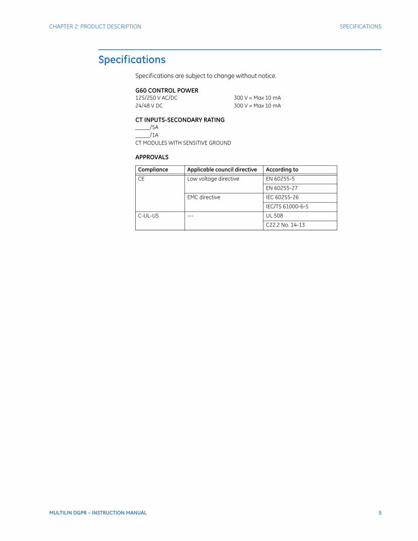
SpecificationsSpecifications are subject to change without notice.
G60 CONTROL POWER125/250 V AC/DC 300 V = Max 10 mA24/48 V DC 300 V = Max 10 mA
CT INPUTS-SECONDARY RATING_____/5A_____/1ACT MODULES WITH SENSITIVE GROUND
APPROVALS
Compliance Applicable council directive According to
CE Low voltage directive EN 60255-5
EN 60255-27
EMC directive IEC 60255-26
IEC/TS 61000-6-5
C-UL-US --- UL 508
C22.2 No. 14-13

6 MULTILIN DGPR – INSTRUCTION MANUAL
SPECIFICATIONS CHAPTER 2: PRODUCT DESCRIPTION
MULTILIN DGPR – INSTRUCTION MANUAL 7
DGPR
Chapter 3: Installation
Installation
This chapter outlines installation of hardware and software.
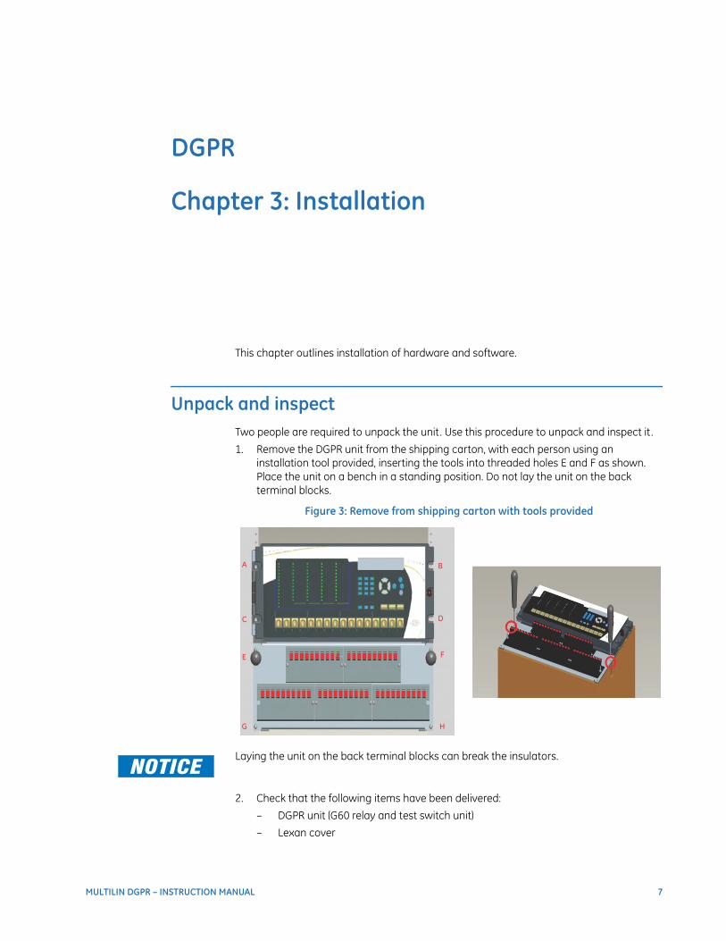
Unpack and inspectTwo people are required to unpack the unit. Use this procedure to unpack and inspect it .
1. Remove the DGPR unit from the shipping carton, with each person using an installation tool provided, inserting the tools into threaded holes E and F as shown. Place the unit on a bench in a standing position. Do not lay the unit on the back terminal blocks.
Figure 3: Remove from shipping carton with tools provided
Laying the unit on the back terminal blocks can break the insulators.
2. Check that the following items have been delivered:
– DGPR unit (G60 relay and test switch unit)
– Lexan cover

8 MULTILIN DGPR – INSTRUCTION MANUAL
UNPACK AND INSPECT CHAPTER 3: INSTALLATION
– GE EnerVista™ DVD for G60 (software and documents)
– GE CD for DGRP (documents)
– Multilin DGPR Instruction Manual (printed copy; soft copy on CD)
– Schematic drawings
– Mounting instructions with installation tools and screws
– Certificate of Calibration
– Test Report
– EC Declaration of Conformity
3. Inspect the unit for physical damage.
4. View the rear nameplates and verify that the correct models have been delivered. On the G60, the model number is on the back of the unit at the top right. On the DGPR chassis, the model number is on the top right.
Figure 4: Checking model numbers
5. For any issues, contact GE Grid Solutions as outlined in the For further assistance section on page 1.
6. Check that you have the latest copy of the Instruction Manual for the applicable firmware version, at http://gegridsolutions.com/multilin/manuals/index.htm
The warranty is included at the end of this instruction manual and on the GE Grid Solutions website.

CHAPTER 3: INSTALLATION PANEL DIMENSIONS
MULTILIN DGPR – INSTRUCTION MANUAL 9
Panel dimensionsThis section outlines the dimensions and panel cutouts. The DGPR dimensions are 14" (height) × 19" (width) × 14" (depth).
Front panelThe figure shows the front dimensions.
Figure 5: Front dimensions
Side layoutThe figure shows the side dimensions.
10 MULTILIN DGPR – INSTRUCTION MANUAL
PANEL DIMENSIONS CHAPTER 3: INSTALLATION
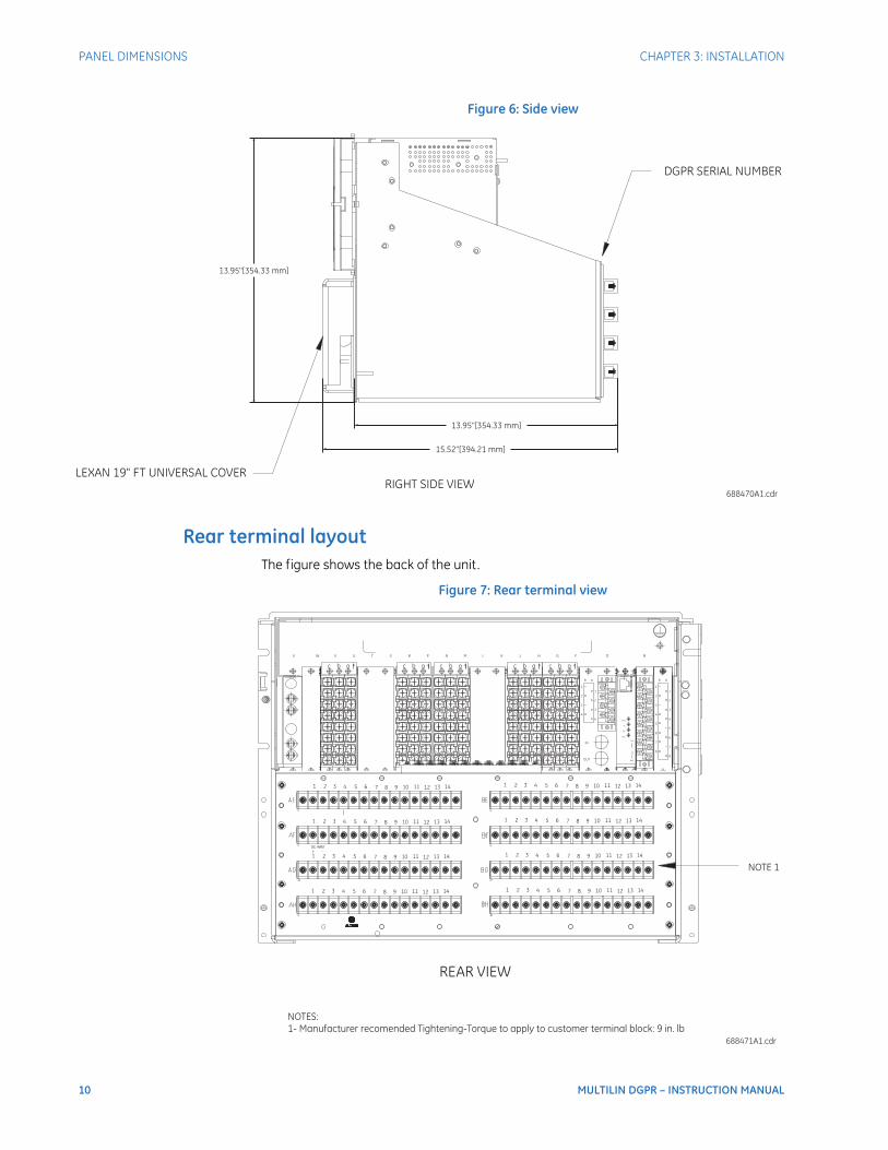
Figure 6: Side view
Rear terminal layoutThe figure shows the back of the unit.
Figure 7: Rear terminal view

CHAPTER 3: INSTALLATION REAR PANEL
MULTILIN DGPR – INSTRUCTION MANUAL 11
Rear panelThe figure shows the back of the G60.
Figure 8: G60 rear panel
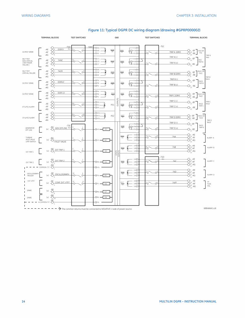
Wiring diagramsA typical wiring diagram for the G60 follows.
Wiring diagrams of typical AC and DC schemes also follow.
Because the connections to the DGPR are the same as the DGP, meaning you disconnect the wires from the DGP and connect them to the same terminal blocks on the DGPR. Except for the power supply alarm connections, see diagram GPRP00002 for details.

12 MULTILIN DGPR – INSTRUCTION MANUAL
WIRING DIAGRAMS CHAPTER 3: INSTALLATION
Figure 9: Typical G60 wiring

CHAPTER 3: INSTALLATION WIRING DIAGRAMS
MULTILIN DGPR – INSTRUCTION MANUAL 13
Figure 10: Typical DGPR AC wiring diagram (drawing #GPRP000002)
14 MULTILIN DGPR – INSTRUCTION MANUAL
WIRING DIAGRAMS CHAPTER 3: INSTALLATION
Figure 11: Typical DGPR DC wiring diagram (drawing #GPRP000002)
CHAPTER 3: INSTALLATION WIRING DIAGRAMS
MULTILIN DGPR – INSTRUCTION MANUAL 15
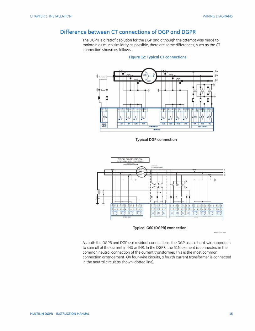
Difference between CT connections of DGP and DGPRThe DGPR is a retrofit solution for the DGP and although the attempt was made to maintain as much similarity as possible, there are some differences, such as the CT connection shown as follows.
Figure 12: Typical CT connections
As both the DGPR and DGP use residual connections, the DGP uses a hard-wire approach to sum all of the current in INS or INR. In the DGPR, the 51N element is connected in the common neutral connection of the current transformer. This is the most common connection arrangement. On four-wire circuits, a fourth current transformer is connected in the neutral circuit as shown (dotted line).
16 MULTILIN DGPR – INSTRUCTION MANUAL
WIRING DIAGRAMS CHAPTER 3: INSTALLATION
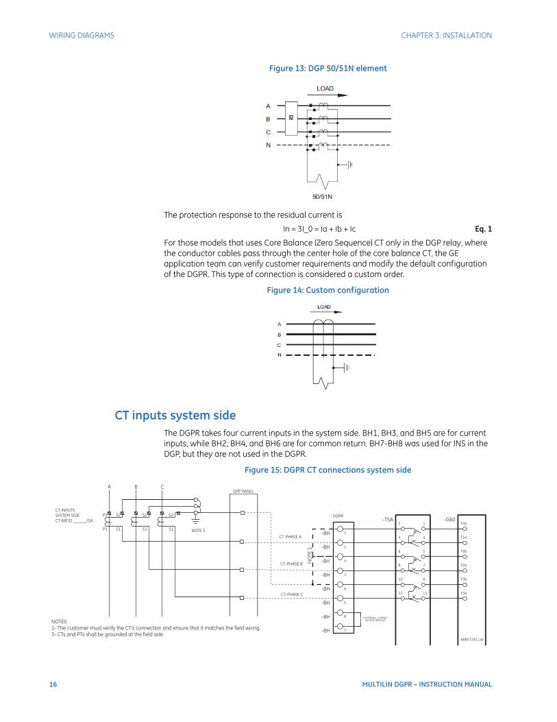
Figure 13: DGP 50/51N element
The protection response to the residual current is
In = 3I_0 = Ia + Ib + Ic Eq. 1
For those models that uses Core Balance (Zero Sequence) CT only in the DGP relay, where the conductor cables pass through the center hole of the core balance CT, the GE application team can verify customer requirements and modify the default configuration of the DGPR. This type of connection is considered a custom order.
Figure 14: Custom configuration
CT inputs system sideThe DGPR takes four current inputs in the system side. BH1, BH3, and BH5 are for current inputs, while BH2, BH4, and BH6 are for common return. BH7-BH8 was used for INS in the DGP, but they are not used in the DGPR.
Figure 15: DGPR CT connections system side

CHAPTER 3: INSTALLATION WIRING DIAGRAMS
MULTILIN DGPR – INSTRUCTION MANUAL 17
CT inputs neutral sideThe DGPR takes four current inputs in the neutral side. AH1, AH3, and AH5 are for current inputs, while AH2, AH4, and AH6 are for common return. AH7-AH8 was used for INR in the DGP, but they are used for 51G or GPM connection in the DGPR.
Figure 16: DGPR CT connections neutral side
Voltage inputsThe DGPR takes four voltage inputs. The DGPR phase voltage inputs can be WYE or DELTA and are derived from the generator terminal voltage. Vx is derived from the generator neutral grounding transformer.

18 MULTILIN DGPR – INSTRUCTION MANUAL
WIRING DIAGRAMS CHAPTER 3: INSTALLATION
Figure 17: DGPR voltage transformer connections
Digital inputs and outputs
InputsSeven digital inputs can be connected to the DGPR.
• DI01 — Generator Offline
• DI02 — Turbine Inlet-valve-close indication
• DI03 — External Trip 1
• DI04 — External Trip 2
• DI05 — Oscillography Trigger
• DI06 — External VTFF
• DI07 — Spare
• DI08 — Spare
OutputsThe DGPR has 18 digital outputs.
• DO01 — Trip A (74G)

CHAPTER 3: INSTALLATION WIRING DIAGRAMS
MULTILIN DGPR – INSTRUCTION MANUAL 19
• DO02 — Trip A (94G)
• DO03 — Trip B (74G1)
• DO04 — Trip B (94G1)
• DO05 — Trip C (74G2)
• DO06 — Trip C (94G2)
• DO07 — Trip D (74G3)
• DO08 — Trip D (94G3)
• DO09 — Spare
• DO10 — Spare
• DO11 — Not used
• DO12 — Not used
• DO13 — Alarm A (74A)
• DO14 — Alarm B (74B)
• DO15 — Alarm C (74C)
• DO16 — Alarm D (74D)
• DO17 — VTFF (74FF)
• DO18 — Spare
• DO19 — Self-Test Non-Critical -Any Minor Failure (74NC)
• DO20 — Self-Test Critical Failure (74CR)
Test switchesFive FT test switches are provided for trip, CT, VT, and DC isolation. The figure is provided for reference.
Figure 18: Test switch configuration
Do not switch the switches under load or similar on units. Do not touch any open blade when the system is energized. Death or serious injury can result.
20 MULTILIN DGPR – INSTRUCTION MANUAL
INSTALL HARDWARE CHAPTER 3: INSTALLATION
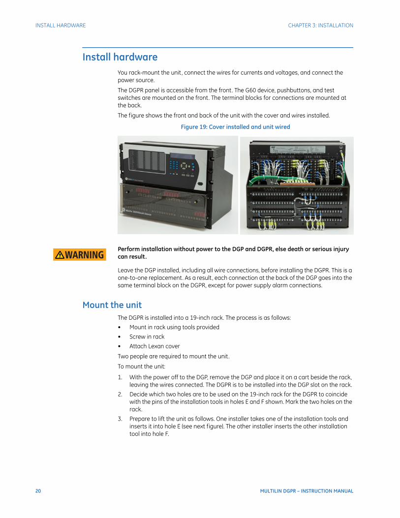
Install hardwareYou rack-mount the unit, connect the wires for currents and voltages, and connect the power source.
The DGPR panel is accessible from the front. The G60 device, pushbuttons, and test switches are mounted on the front. The terminal blocks for connections are mounted at the back.
The figure shows the front and back of the unit with the cover and wires installed.
Figure 19: Cover installed and unit wired
Perform installation without power to the DGP and DGPR, else death or serious injury can result.
Leave the DGP installed, including all wire connections, before installing the DGPR. This is a one-to-one replacement. As a result, each connection at the back of the DGP goes into the same terminal block on the DGPR, except for power supply alarm connections.
Mount the unitThe DGPR is installed into a 19-inch rack. The process is as follows:
• Mount in rack using tools provided
• Screw in rack
• Attach Lexan cover
Two people are required to mount the unit.
To mount the unit:
1. With the power off to the DGP, remove the DGP and place it on a cart beside the rack, leaving the wires connected. The DGPR is to be installed into the DGP slot on the rack.
2. Decide which two holes are to be used on the 19-inch rack for the DGPR to coincide with the pins of the installation tools in holes E and F shown. Mark the two holes on the rack.
3. Prepare to lift the unit as follows. One installer takes one of the installation tools and inserts it into hole E (see next figure). The other installer inserts the other installation tool into hole F.
CHAPTER 3: INSTALLATION INSTALL HARDWARE
MULTILIN DGPR – INSTRUCTION MANUAL 21
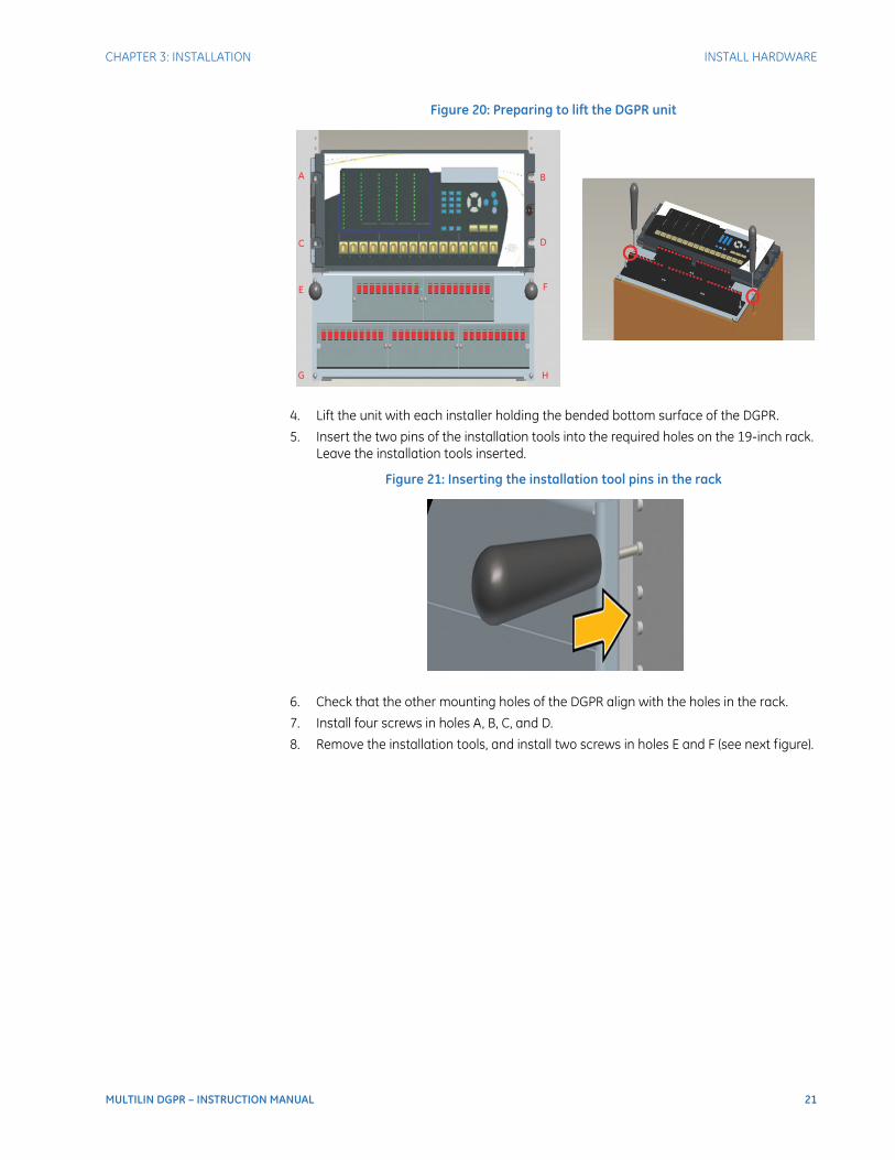
Figure 20: Preparing to lift the DGPR unit
4. Lift the unit with each installer holding the bended bottom surface of the DGPR.
5. Insert the two pins of the installation tools into the required holes on the 19-inch rack. Leave the installation tools inserted.
Figure 21: Inserting the installation tool pins in the rack
6. Check that the other mounting holes of the DGPR align with the holes in the rack.
7. Install four screws in holes A, B, C, and D.
8. Remove the installation tools, and install two screws in holes E and F (see next figure).
22 MULTILIN DGPR – INSTRUCTION MANUAL
INSTALL HARDWARE CHAPTER 3: INSTALLATION
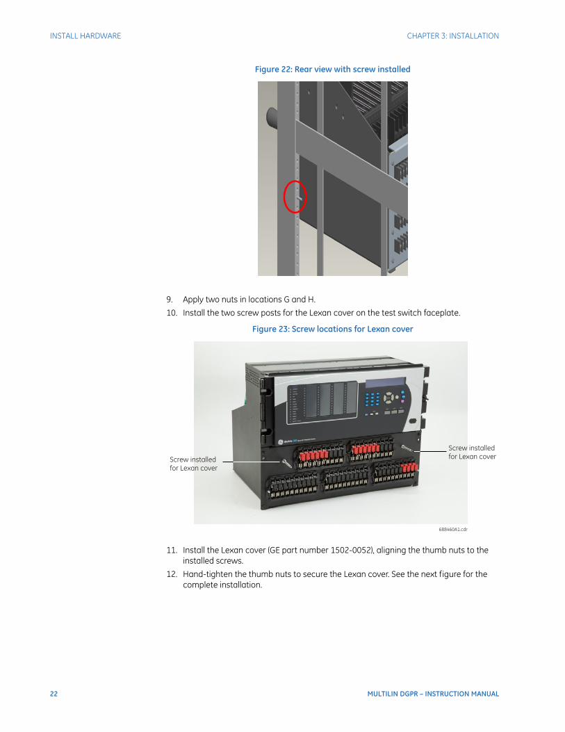
Figure 22: Rear view with screw installed
9. Apply two nuts in locations G and H.
10. Install the two screw posts for the Lexan cover on the test switch faceplate.
Figure 23: Screw locations for Lexan cover
11. Install the Lexan cover (GE part number 1502-0052), aligning the thumb nuts to the installed screws.
12. Hand-tighten the thumb nuts to secure the Lexan cover. See the next figure for the complete installation.

CHAPTER 3: INSTALLATION INSTALL HARDWARE
MULTILIN DGPR – INSTRUCTION MANUAL 23
Figure 24: Cover installed

24 MULTILIN DGPR – INSTRUCTION MANUAL
INSTALL HARDWARE CHAPTER 3: INSTALLATION
Connect the wiresThe first step in wiring involves connecting the currents, voltages, digital inputs, and digital outputs to terminals blocks at the back of the switch panel as per the DGPR wiring diagram. The digital inputs and outputs are also referred to as contact inputs and outputs.
There are eight 14 pole-terminal blocks at the back of the unit, designated as AE, AF, AG, AH, BE, BF, BG, and BH. The current transformer (CT) and voltage transformer (VT) wires are connected to the bottom two rows. The contact inputs and outputs are connected to the top two rows.
Figure 25: DGPR back panel connections
To connect the wires:
1. With power off to the DGP, take the CT and VT inputs on the DGP and connect them to the same terminal blocks AH and BH on the outside at the back the DGPR chassis. Each connection on the DGP goes in the same terminal block on the DGPR. Use wiring diagram DWG # GPRP000002 as a reference.
2. Take the digital inputs and outputs from the DGP and connect them to terminal blocks AE, AF, AG, BE, BF, and BG on the outside at the back of the DGPR chassis. Each connection on the DGP goes in the same terminal block on the DGRP. Refer to a wiring diagram. Note that the power connections also go into AG and BG; move them now after reading the next section or wait.

CHAPTER 3: INSTALLATION INSTALL HARDWARE
MULTILIN DGPR – INSTRUCTION MANUAL 25
Connect the power supplyThe DGPR has redundant power supply. The right-most module at the back of the G60 (slots A and B) is the main power supply module. The left-most module is the redundant power supply module (slots W and X). Power is connected and grounded on the back of the G60 at the top right.
The DGPR has a grounding bar. Eight connection points ground each of the eight G60 modules, including the two power supplies. These eight connections points connect the G60 to the DGPR chassis. They are installed in the factory. In addition, the DGPR grounding bar must be connected directly to the generator protection panel grounding bus.
Figure 26: Connecting ground to top of chassis (six of eight connections shown, installed in factory)
To ground the DGPR:
1. Using a wire, connect the DGPR ground bus to the panel/rack grounding bus. The recommended minimum wire size for the connection is 6 AWG. For example, attach the wire to the "ground connection point" shown in the previous figure.
The power connects to the terminal blocks on the back of the DGPR. The connections are same as on the DGP.
To connect the power supply:
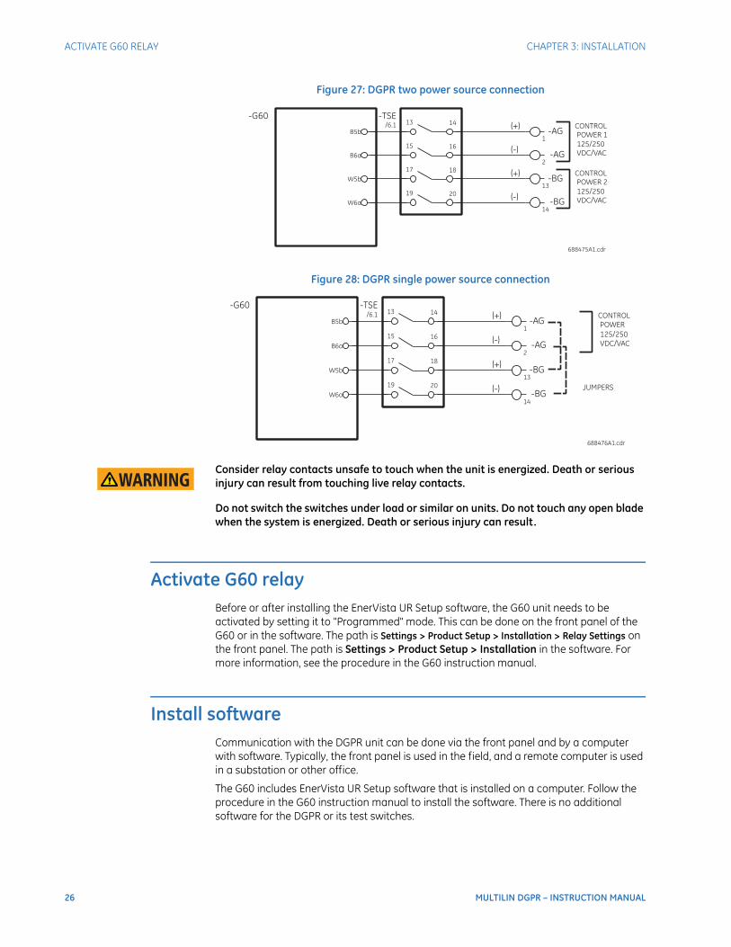
1. With power off to the DGP, take the power connections from the back of the DGP and connect them to the back of the DGPR. That is, connect the control power supplied to the relay to terminal block AG1 (+) and AG2 (-) for Power Supply # 1 and BG13 (+) and BG14 (-) for Power Supply # 2. See Figure 27.
If there is only one power source, install jumpers between AG1-BG13 (+) and AG2-BG14 (-) and connect the power to AG1 (+) and AG2 (-). See Figure 28.
26 MULTILIN DGPR – INSTRUCTION MANUAL
ACTIVATE G60 RELAY CHAPTER 3: INSTALLATION
Figure 27: DGPR two power source connection
Figure 28: DGPR single power source connection
Consider relay contacts unsafe to touch when the unit is energized. Death or serious injury can result from touching live relay contacts.
Do not switch the switches under load or similar on units. Do not touch any open blade when the system is energized. Death or serious injury can result.
Activate G60 relayBefore or after installing the EnerVista UR Setup software, the G60 unit needs to be activated by setting it to "Programmed" mode. This can be done on the front panel of the G60 or in the software. The path is Settings > Product Setup > Installation > Relay Settings on the front panel. The path is Settings > Product Setup > Installation in the software. For more information, see the procedure in the G60 instruction manual.
Install softwareCommunication with the DGPR unit can be done via the front panel and by a computer with software. Typically, the front panel is used in the field, and a remote computer is used in a substation or other office.
The G60 includes EnerVista UR Setup software that is installed on a computer. Follow the procedure in the G60 instruction manual to install the software. There is no additional software for the DGPR or its test switches.
CHAPTER 3: INSTALLATION CONNECT G60 RELAY
MULTILIN DGPR – INSTRUCTION MANUAL 27
Connect G60 relayThe G60 is connected typically to a network for communication with other devices, for example using the Ethernet port. It also connects to a computer running the EnerVista software, either on-site using the RS232 port or remotely using the Ethernet port, for example.
There are three ways to connect the G60:
• RS232 port
• Ethernet port
• RS485 port
Connect the computer/network and relay now using one of the three connection options.
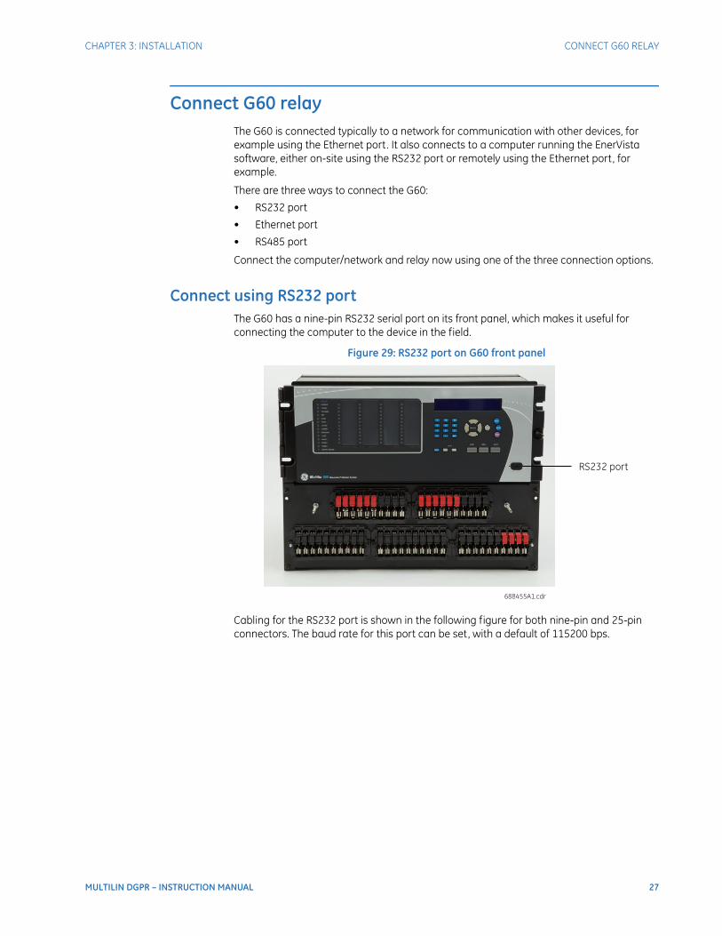
Connect using RS232 portThe G60 has a nine-pin RS232 serial port on its front panel, which makes it useful for connecting the computer to the device in the field.
Figure 29: RS232 port on G60 front panel
Cabling for the RS232 port is shown in the following figure for both nine-pin and 25-pin connectors. The baud rate for this port can be set, with a default of 115200 bps.
28 MULTILIN DGPR – INSTRUCTION MANUAL
CONNECT G60 RELAY CHAPTER 3: INSTALLATION
Figure 30: RS232 faceplate port connection
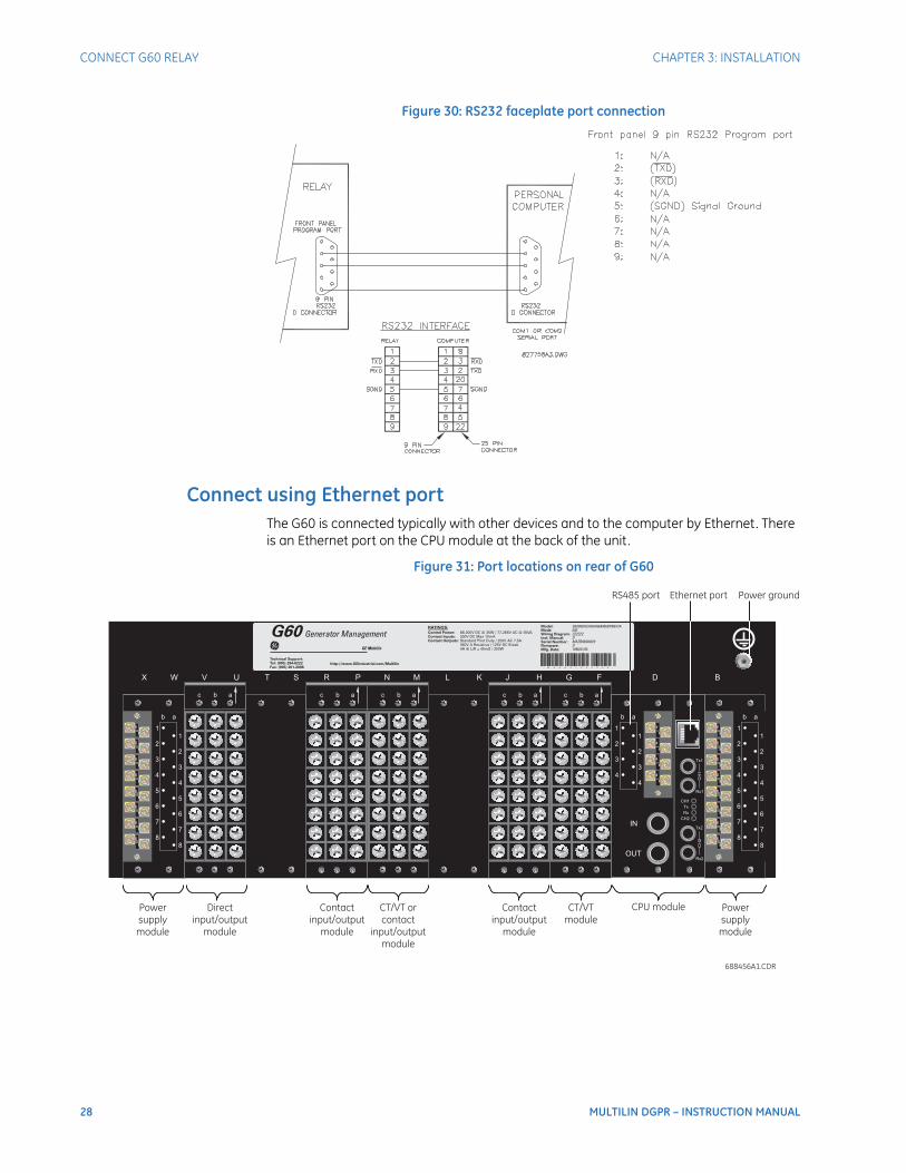
Connect using Ethernet portThe G60 is connected typically with other devices and to the computer by Ethernet. There is an Ethernet port on the CPU module at the back of the unit.
Figure 31: Port locations on rear of G60

CHAPTER 3: INSTALLATION IRIG-B
MULTILIN DGPR – INSTRUCTION MANUAL 29
Connect using RS485 portThe rear of the G60 has a serial RS485 port that can also be used for communication. It is on the CPU module. See the G60 instruction manual for more information.
RS485 data transmission and reception are accomplished over a single twisted pair with transmit and receive data alternating over the same two wires. Through the use of these ports, continuous monitoring and control from a remote computer, SCADA system, or power line carrier (PLC) is possible. To minimize errors from noise, the use of shielded twisted pair wire is recommended. Correct polarity must also be observed.
IRIG-BIRIG-B is a standard time code format that allows stamping of events to be synchronized among connected devices. The IRIG-B code allows time accuracies of up to 100 ns. Using the IRIG-B input, the G60 operates an internal oscillator with 1 µs resolution and accuracy. The GE MultiSync 100 1588 GPS Clock as well as third-party equipment are available for generating the IRIG-B signal; this equipment can use a global positioning system (GPS) satellite system to obtain the time reference so that devices at different geographic locations can be synchronized.
You can optionally use IRIG-B for timing. See the G60 instruction manual for information.
With installation of the DGPR complete, use the G6 instruction manual to program the settings.

30 MULTILIN DGPR – INSTRUCTION MANUAL
IRIG-B CHAPTER 3: INSTALLATION
MULTILIN DGPR – INSTRUCTION MANUAL 31
DGPR
Chapter 4: Maintenance
Maintenance
This chapter outlines maintenance. For maintenance of the G60, see its instruction manual.
RepairsThe battery and modules inside the case can be replaced without return of the device to the factory. The firmware and software can be upgraded without return of the device to the factory.
To return the unit to the factory for repair, use the procedure outlined here or the detailed return procedure outlined at
https://www.gegridsolutions.com/multilin/support/ret_proc.htm
The process to return the device to the factory for repair is as follows:
• Contact a GE Grid Solutions Technical Support Center as outlined in the For further assistance section on page 1.
• Obtain a Return Materials Authorization (RMA) number from the Technical Support Center.
• Verify that the RMA and Commercial Invoice received have the correct information.
• Use the original shipping carton if possible. Otherwise, tightly pack the unit in a box with bubble wrap, foam material, styrofoam inserts, or packaging peanuts to cushion the item(s). You can also use double boxing whereby you place the box in a larger box that contains at least 5 cm of cushioning material.
• Ship the unit by courier or freight forwarder, along with the Commercial Invoice and RMA, to the factory.
GE GRID SOLUTIONS
650 MARKLAND STREET
MARKHAM, ONTARIO
CANADA L6C 0M1
ATTN: SERVICE DEPT.
RMA# : ______________

32 MULTILIN DGPR – INSTRUCTION MANUAL
REPAIRS CHAPTER 4: MAINTENANCE
Customers are responsible for shipping costs to the factory, regardless of whether the unit is under warranty.
• Fax a copy of the shipping information to the GE Grid Solutions service department in Canada at +1 905 927 5098.
MULTILIN DGPR – INSTRUCTION MANUAL 33
DGPR
Appendix A: Miscellaneous
Appendices Miscellaneous
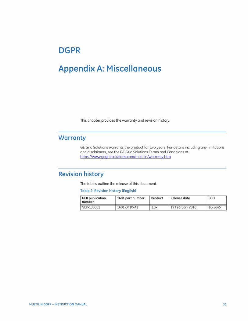
This chapter provides the warranty and revision history.
WarrantyGE Grid Solutions warrants the product for two years. For details including any limitations and disclaimers, see the GE Grid Solutions Terms and Conditions at https://www.gegridsolutions.com/multilin/warranty.htm
Revision historyThe tables outline the release of this document.
Table 2: Revision history (English)
GEK publication number
1601 part number Product Release date ECO
GEK-130861 1601-0410-A1 1.0x 19 February 2016 16-2645

34 MULTILIN DGPR – INSTRUCTION MANUAL
REVISION HISTORY APPENDIX A: MISCELLANEOUS

MULTILIN DGPR – INSTRUCTION MANUAL 35
DGPR
Index
Index
AActivate G60 ............................................................................................... 26Approvals, certification ...........................................................................5
BBack panel ............................................................................................10, 11
CCE certification .............................................................................................5Certification ....................................................................................................5Changes ........................................................................................................ 33Communication ports ........................................................................... 27Compliance ....................................................................................................5Connect G60 ............................................................................................... 27Connect power .......................................................................................... 25Connect wires ............................................................................................ 24Contact inputs and outputs ............................................................... 18CSA certification ..........................................................................................5CT connection differences .................................................................. 15CT input diagrams ................................................................................... 16
DDescription .....................................................................................................3Digital inputs and outputs .................................................................. 18Dimensions .....................................................................................................9
EEthernet port .............................................................................................. 28
FFeatures ........................................................................................................... 3Front panel dimensions .......................................................................... 9FT test switches .........................................................................................19
GG60
activate ......................................................................................................26communication ports ..........................................................................27
Ground power ............................................................................................25Guarantee ....................................................................................................33
HHardware installation ............................................................................20Help, getting .................................................................................................. 1
IInputs ..............................................................................................................18Install
hardware ..................................................................................................20mount .........................................................................................................20power connection .................................................................................25software ....................................................................................................26wires ............................................................................................................24
IRIG-B ..............................................................................................................29
LLPS-O ................................................................................................................. 4

36 MULTILIN DGPR – INSTRUCTION MANUAL
INDEX
MModel number ..............................................................................................7Mount the unit ...........................................................................................20
NNameplate, rear ..........................................................................................7
OOrder codes ....................................................................................................4Outputs ..........................................................................................................18
PPanel cutouts ................................................................................................9Part numbering ............................................................................................4Ports for communications ..................................................................27Power connection ....................................................................................25Power ground ............................................................................................25
RRack installation .......................................................................................20Rear G60 layout ........................................................................................11Rear terminal layout ..............................................................................10Repair ..................................................................................................1, 31, 33Revision history of instruction manual ........................................33RS232 port ...................................................................................................27RS485 port ...................................................................................................29
SSafety symbols .............................................................................................1Serial number ................................................................................................7Settings .............................................................................................................4Side view ..........................................................................................................9Software installation ..............................................................................26Specifications ................................................................................................5Standards, certification ...........................................................................5Support, technical ......................................................................................1Symbols, safety ............................................................................................1
TTechnical specifications ..........................................................................5Technical support .......................................................................................1Test switches ..............................................................................................19Time source .................................................................................................29Time-stamping using IRIG-B .............................................................29
UUL certification ............................................................................................. 5Unpacking the relay ................................................................................. 7Updates to instruction manual .......................................................... 8
VVoltage input diagrams ........................................................................17
WWarranty .......................................................................................................33What is in the box ...................................................................................... 7Wire connections .....................................................................................24Wiring diagrams .......................................................................................11