
GE Fanuc Automation Fanuc Automation ... Chapter 2. Description: Chapter 2 describes the Genius Bus...
248
GE Fanuc Automation Programmable Control Products Field Control™ Genius® Bus Interface Unit User’s Manual GFK-0825F October 1999
Transcript of GE Fanuc Automation Fanuc Automation ... Chapter 2. Description: Chapter 2 describes the Genius Bus...

GE Fanuc Automation
Programmable Control Products
Field Control™Genius® Bus Interface Unit
User’s Manual
GFK-0825F October 1999

GFL-002
Warnings, Cautions, and Notesas Used in this Publication
Warning
Warning notices are used in this publication to emphasize that hazardous voltages,currents, temperatures, or other conditions that could cause personal injury exist in thisequipment or may be associated with its use.
In situations where inattention could cause either personal injury or damage toequipment, a Warning notice is used.
Caution
Caution notices are used where equipment might be damaged if care is not taken.
NoteNotes merely call attention to information that is especially significant to understanding andoperating the equipment.
This document is based on information available at the time of its publication. While effortshave been made to be accurate, the information contained herein does not purport to cover alldetails or variations in hardware or software, nor to provide for every possible contingency inconnection with installation, operation, or maintenance. Features may be described hereinwhich are not present in all hardware and software systems. GE Fanuc Automation assumes noobligation of notice to holders of this document with respect to changes subsequently made.
GE Fanuc Automation makes no representation or warranty, expressed, implied, or statutorywith respect to, and assumes no responsibility for the accuracy, completeness, sufficiency, orusefulness of the information contained herein. No warranties of merchantability or fitness forpurpose shall apply.
The following are trademarks of GE Fanuc Automation North America, Inc.
Alarm Master Genius ProLoop Series ThreeCIMPLICITY Helpmate PROMACRO VersaMaxCIMPLICITY 90–ADS Logicmaster Series Five VersaProCIMSTAR Modelmaster Series 90 VuMasterField Control Motion Mate Series One WorkmasterGEnet PowerTRAC Series Six
©Copyright 1996-1999 GE Fanuc Automation North America, Inc.All Rights Reserved.

Preface
GFK-0825F iii
Content of this Manual
This manual describes the Field Control® Genius™ Bus Interface Unit (IC670GBI002). It explainsoperation of the Bus Interface Unit as a Genius bus device. It also contains complete configurationinstructions for the Bus Interface Unit and all Field Control I/O modules.
Chapter 1. Introduction: Chapter 1 introduces Field Control systems, the Genius Bus InterfaceUnit, and other equipment that may be used with the Bus Interface Unit. It will help you locatemore information about the components and operation of Field Control products.
Chapter 2. Description: Chapter 2 describes the Genius Bus Interface Unit module, the BusInterface Unit Power Supply, and the Bus Interface Unit Terminal Block, and lists theirspecifications.
Chapter 3. Installation: Chapter 3 describes Bus Interface Unit installation and gives systeminstallation guidelines.
Chapter 4. Operation: Chapter 4 explains how a Bus Interface Unit interacts with the modules inits station, how it stores data, and how it exchanges data with a PLC or other type of system host.
Chapter 5. Station Configuration: Chapter 5 explains how to configure a Bus Interface Unit andthe modules in a station using a Hand-held Monitor.
Chapter 6. Diagnostics and Fault Clearing: Chapter 6 describes the diagnostics capabilities ofthe Bus Interface Unit and explains how faults are cleared.
Chapter 7. Monitoring and Controlling Field Control Data: Chapter 7 explains how to monitoror control Field Control I/O data using Genius Hand-held Monitor or a programmer.
Chapter 8. Datagrams: Chapter 8 lists datagrams that can be sent to a Bus Interface Unit, andshows the datagram formats for Field Control modules.
Appendix A. Scaling Analog Channels: Appendix A explains how to select scaling values whenconfiguring an analog input or output. (Configuration instructions are in chapter 5).
Appendix B. Installing Additional Suppression: Appendix B describes some precautions thatcan be taken in an installation to help assure proper operation.
Appendix C. The Genius Serial Bus: This appendix describes the selection and operatingcharacteristics of the bus cable that links Genius devices.
Appendix D. Configuration Examples: This appendix includes examples of different Field Control I/OStation configurations.

Preface
iv Field Control™ Genius® Bus Interface Unit User’s Manual– October 1999 GFK-0825F
Related Publications
For more information, refer to these publications:
Field Control I/O Modules User's Manual (GFK-0826). This book describes Field Control I/OModules and I/O Terminal Blocks and explains how to install them.
The Series 90® Micro Field Processor User's Manual (GFK-1171). This book describes theMicro Field Processor (IC670MFP100) and provides installation procedures, operationinformation, and diagnostics information.
Genius I/O System User's Manual (GEK-90486-1). Reference manual for system designers,programmers, and others involved in integrating Genius I/O products in a PLC or host computerenvironment. This book provides a system overview, and describes the types of systems that can becreated using Genius products. Datagrams, Global Data, and data formats are defined.
Series 90® −30 Bus Controller User's Manual (GFK-1034). Reference manual for the BusController, which interfaces a Genius bus to a Series 90-30 PLC. This book describes theinstallation and operation of the Bus Controller.
Series Six® Bus Controller User's Manual (GFK-0171). Reference manual for the Bus Controller,which interfaces a Genius bus to a Series Six PLC. This book describes the installation andoperation of the Bus Controller. It also contains the programming information needed to interfaceGenius I/O devices to a Series Six PLC.
Series Five® Bus Controller User's Manual (GFK-0248). Reference manual for the BusController, which interfaces a Genius bus to a Series Five PLC. This book describes the installationand operation of the Bus Controller. It also contains the programming information needed tointerface Genius I/O devices to a Series Five PLC.
Genius I/O PCIM User's Manual (GFK-0074). Reference manual for the PCIM, which interfacesa Genius bus to a suitable host computer. This book describes the installation and operation of thePCIM. It also contains the programming information needed to interface Genius I/O devices to ahost computer.
Installation Requirements for Conformance to Standards (GFK-1179)
Jeanne GrimsbyLead Technical Writer for I/O Products

Contents
GFK-0825F v
Chapter 1 Introduction..................................................................................................... 1-1
Overview......................................................................................................................1-1
Field Control Modules ..................................................................................................1-2
Environmental Specifications........................................................................................1-5
Configuration for Field Control.....................................................................................1-6
Field Control in a Genius System..................................................................................1-7Required Genius and Host System Equipment...............................................................1-9
Using Field Control in a CPU Redundancy System..................................................... 1-10
Using Field Control in a Genius Bus Redundancy System........................................... 1-11
Chapter 2 Description....................................................................................................... 2-1
Genius Bus Interface Unit .............................................................................................2-1
Bus Interface Unit Power Supply..................................................................................2-3Backplane Current ........................................................................................................2-4Bus Interface Unit Power Dissipation............................................................................2-5Load Requirements for Hardware Components .............................................................2-6
Bus Interface Unit Terminal Block................................................................................2-8
Functional Specifications..............................................................................................2-9
Chapter 3 Installation....................................................................................................... 3-1
Preinstallation Check ....................................................................................................3-2Static Protection............................................................................................................3-2Hand-held Monitor Connector ......................................................................................3-2
System Wiring Guidelines ............................................................................................3-3Installing Additional Suppression..................................................................................3-3
System Grounding ........................................................................................................3-4
Locations for Field Control...........................................................................................3-5Installing the DIN Rail..................................................................................................3-5
Installing the Bus Interface Unit Terminal Block on the DIN Rail .................................3-7
Installing the Cables Between Terminal Blocks.............................................................3-8
Power Wiring to the Bus Interface Unit.........................................................................3-9
Connecting the Communications Bus.......................................................................... 3-10Bus Cables.................................................................................................................. 3-10Making Bus Connections ............................................................................................ 3-11
Installing the Bus Interface Unit on the Terminal Block .............................................. 3-14Removing the Bus Interface Unit from the Terminal Block ......................................... 3-14
Removing/Replacing the Bus Interface Unit Fuse ....................................................... 3-15
Upgrading the BIU Firmware...................................................................................... 3-16

Contents
vi Field Control™ Genius® Bus Interface Unit User’s Manual– October 1999 GFK-0825F
Chapter 4 Operation......................................................................................................... 4-1
BIU Data Handling at the I/O Station............................................................................4-2I/O Data for Conventional Modules ..............................................................................4-3I/O Data, Status Data, and Control Data for Intelligent Modules....................................4-3Group Data for Intelligent Modules...............................................................................4-4
The BIU Sweep ............................................................................................................4-5
BIU Backplane Scan Time............................................................................................4-7
Data Transfer Between the BIU and the Host ................................................................4-9Data in the BIU's Network (Bus) Map...........................................................................4-9Communications on the Genius Bus..............................................................................4-9
Input Data Sent by the Bus Interface Unit ................................................................... 4-10Outputs from the Host to the BIU................................................................................ 4-11
Genius Bus Scan Time................................................................................................ 4-12
Operation of the BIU with a Micro Field Processor ..................................................... 4-14MFP and BIU Synchronization ................................................................................... 4-14MFP I/O References ................................................................................................... 4-14MFP Operating Modes................................................................................................ 4-14Overview of Synchronous Operation........................................................................... 4-16Backing Up Micro Field Processor Outputs ................................................................ 4-17How the Network Backs Up MFP Outputs.................................................................. 4-18Backing Up BIU Outputs with a Micro Field Processor............................................... 4-19Example Ladder Logic................................................................................................ 4-20
Chapter 5 Station Configuration...................................................................................... 5-1
For Additional Information, Also See: ..........................................................................5-1
Configuring the Serial Bus Address and Baud Rate.......................................................5-2Special Instructions for Series 90-70 PLC Systems .......................................................5-2
Set Up the Hand-held Monitor ......................................................................................5-3
Create a New Configuration..........................................................................................5-4Assigning a Serial Bus Address to a New BIU ..............................................................5-4
Configure the Bus Interface Unit...................................................................................5-5Field Control HHM Menu Overview.............................................................................5-6Change the Serial Bus Address of the Bus Interface Unit ..............................................5-7Select the Baud Rate.....................................................................................................5-8Select a Series Six or Series Five PLC Reference Address.............................................5-9Configure Fault Reporting .......................................................................................... 5-10Configure Genius Bus Redundancy............................................................................. 5-11Configure CPU Redundancy....................................................................................... 5-12
Configure Field Control Modules................................................................................ 5-15Enable/Disable the I/O Scan ....................................................................................... 5-15

Contents
GFK-0825F Contents vii
Disable Network I/O Updates ..................................................................................... 5-15
Configure the Network Map for the Bus Interface Unit ............................................... 5-16Configuring Extra References in the BIU I/O Map...................................................... 5-17Add Modules and Assign References .......................................................................... 5-20Configure a Discrete Input Module ............................................................................. 5-22Configure a Discrete Output Module........................................................................... 5-24Configure a Discrete Input/Output Module.................................................................. 5-26Configure a Conventional Analog Input Module ......................................................... 5-29Configure a Conventional Analog Output Module....................................................... 5-35Configure a 16-Point Grouped Analog Input Module .................................................. 5-40Configure an 8-Point Grouped Analog Voltage Input Module ..................................... 5-48Configure a 16-Point Grouped Analog Voltage Input Module ..................................... 5-56Circuit Configuration.................................................................................................. 5-60Configure an RTD Input Module ................................................................................ 5-64Circuit Configuration.................................................................................................. 5-67Configuring a Thermocouple Input Module................................................................. 5-72Configure an 8-Point Analog Voltage Output Module................................................. 5-81Configure an 8-Point Analog Current Output Module ................................................. 5-90Configure a Micro Field Processor.............................................................................. 5-99
Chapter 6 Diagnostics and Fault Clearing....................................................................... 6-1
Diagnostics and Fault Clearing for Intelligent Modules .................................................6-1
Diagnostics and Fault Clearing for the BIU and Conventional Modules.........................6-2
Display and Clear Faults from a Genius Hand-held Monitor..........................................6-3
Display and Clear Faults from a PLC............................................................................6-5Series 90 PLC: I/O Fault Table ....................................................................................6-5Series 90 PLC: PLC Fault Table ...................................................................................6-5Series Five or Series Six PLC .......................................................................................6-5

Contents
viii Field Control™ Genius® Bus Interface Unit User’s Manual– October 1999 GFK-0825F
Chapter 7 Monitoring and Controlling Field Control Data............................................ 7-1
Overview......................................................................................................................7-2Forcing Circuits............................................................................................................7-2Overriding I/O Circuits .................................................................................................7-2
Monitor/Control I/O Data: Genius Hand-held Monitor ..................................................7-3Forcing/Unforcing the Displayed Reference..................................................................7-5
Monitor/Control I/O Data: Series 90 PLC ....................................................................7-6
Monitor/Control I/O Data: Series Six PLC or Series Five PLC.....................................7-6
Monitor/Control I/O Data: Computer ............................................................................7-7
Chapter 8 Datagrams ....................................................................................................... 8-1
Datagram Types............................................................................................................8-2Read Map.....................................................................................................................8-3Read Map Reply...........................................................................................................8-3Write Map ....................................................................................................................8-4Report Fault Datagram Format......................................................................................8-5Configuration Data .......................................................................................................8-7Read Configuration Data ..............................................................................................8-7Set Bus Interface Unit Operating Mode....................................................................... 8-29Set Micro Field Processor Operating Mode................................................................. 8-29Intelligent Analog Module Recalibration Datagram..................................................... 8-30Read I/O Forces.......................................................................................................... 8-32Read I/O Forces Reply................................................................................................ 8-32Read Slot Diagnostics ................................................................................................. 8-33Read Slot Diagnostics Reply....................................................................................... 8-33

Contents
GFK-0825F Contents ix
Appendix A Scaling Analog Channels.................................................................................A-1
How Scaling Works..................................................................................................... A-1Scaling Values for 1mV or 1µA Engineering Units: BIU Version 1.3........................... A-2Scaling Values for 1mV or 1µA Engineering Units: BIU.............................................. A-3Measuring Scaling Values............................................................................................ A-4Example of Scaling an Analog Input ............................................................................ A-5
Appendix B Installing Additional Suppression ..................................................................B-1
Suppression at the Power Lines.................................................................................... B-1Suppression for Devices in an Enclosure...................................................................... B-2Suppression at the Communications Line..................................................................... B-2
Appendix C The Genius Serial Bus.....................................................................................C-1
Wiring Guidelines........................................................................................................ C-1Electrical Interface....................................................................................................... C-2Genius Transceiver Electrical Specification ................................................................. C-3Selecting a Cable Type ................................................................................................ C-4Serial Bus Waveforms ................................................................................................. C-5Using Other Cable Types............................................................................................. C-6Serial Data Format....................................................................................................... C-8Bus Access .................................................................................................................. C-9Bus Length ................................................................................................................ C-10Baud Rate Selection................................................................................................... C-10Bus Ambient Electrical Information........................................................................... C-11Lightning Transient Suppression................................................................................ C-11
Appendix D Configuration Examples .................................................................................D-1
Example 1: Discrete Data, Network Processing............................................................ D-1Example 2: Discrete and Analog Data, Network Processing ......................................... D-2Example 3: Discrete and Analog Data, Network and Local Processing......................... D-3Example 4: Discrete and Analog Data, Network and Local Processing and Group Data
Moves ...................................................................................................................... D-4Example 5: Group Move............................................................................................. D-6

GFK-0825F 1-1
BusInterfaceUnit
I/O
I/O
I/O
I/O
I/O
I/O
I/O
I/O
Introduction
This chapter introduces Field Control modules, the Genius Bus Interface Unit, and otherequipment that may be used with the Bus Interface Unit. It will help you locate more informationin other Field Control and Genius documents.
Overview
Field Control is a family of highly modular distributed I/O and control products. They are suitablefor use in a wide range of host architectures.
The heart of the Field Control system is the Bus Interface Unit. The Bus Interface Unit providesintelligent processing, I/O scanning, and feature configuration for a group of up to eight I/Omodules. Together, the Bus Interface Unit and its modules make up a Field Control station (see theillustration, left).
The Bus Interface Unit and I/O modules are enclosed in sturdy, compact aluminum housings. BusInterface Unit and I/O modules bolt securely to separate Terminal Blocks, which provide all fieldwiring terminals. The I/O Terminal blocks are generic and allow different I/O module types to bemounted on the same base. I/O Terminal Blocks are available with box-type terminals, barrier-typeterminals, or wire-to-board connectors. All Terminal Blocks must be mounted on a DIN rail. TheDIN rail, which serves as an integral part of the grounding system, can also be mounted on a panel.
Field Control FeaturesFeatures and benefits of Field Control include:
wiring savings better up time easy installation and maintenance spare parts savings low cost feature flexibility open architecture / adaptable to a variety of networks distributed I/O small, compact I/O modules with generic terminal wiring bases.
DIN rail mounted
1Chapter

1-2 Field Control™ Genius® Bus Interface Unit User’s Manual – October 1999 GFK-0825F
1
Field Control Modules
There are three basic types of Field Control modules:
Bus Interface Unit. The illustration below shows a Genius Bus Interface Unit.
I/O modules
Micro Field Processor
Terminal Blocks:
Bus Interface Unit Terminal Block.
I/O Terminal Blocks, each of which accommodates two I/O modules.
Auxiliary Terminal Blocks. These optional terminal strips can be connected to the side ofan I/O Terminal Block if extra common terminals are needed.
GeniusBus Interface UnitBus Interface Unit
Terminal Block
I/O TerminalBlockAuxiliary
Terminal Blocks I/O Modules
MicroField Processor

GFK-0825F Chapter 1 Introduction 1-3
1
Genius Bus Interface UnitThe Genius Bus Interface Unit (IC670GBI002 or IC697GBI102) interfaces Field Control I/Omodules to a host PLC or computer via a Genius bus. It can exchange up to 128 bytes of input dataand 128 bytes of output data with the host, each Genius bus scan. It can also handle Geniusdatagram communications.
The intelligent processing capabilities of the Genius Bus Interface Unit allow the configuration offeatures such as fault reporting, selectable input and output defaults, analog scaling and analogrange selection for the modules in the station. In addition, the Genius Bus Interface Unit performsdiagnostic checks on itself and its I/O modules, and relays diagnostic information to the host (ifconfigured for fault reporting) and to a Hand-held Monitor.
The Genius Bus Interface Unit can be used on a bus controlled by redundant CPUs or BusControllers. It can also be used on a dual bus.
The Bus Interface Unit mounts on a Bus Interface Unit Terminal Block. It can be removed andreplaced if necessary without removing the wiring or reconfiguring the I/O station.
Bus Interface Unit Terminal Block
The Bus Interface Unit Terminal Block, which included with the BIU, has connections for powerwiring and single or dual communications cables. It has built-in bus switching circuitry, allowingthe Bus Interface Unit to be used on a dual (redundant) Genius bus (no external Bus SwitchingModule is needed). The Bus Interface Unit Terminal Block stores the configuration parametersselected for the station.
I/O Modules
Field Control I/O Modules are available in many types to suit a wide range of application needs.Modules can be installed and removed without disturbing field wiring. One or two I/O modulesmay be mounted on an I/O Terminal Block.
Micro Field Processor
The Series 90 Micro Field Processor (MFP) is a Micro PLC that provides local logic within a FieldControl station. The Micro Field Processor is the same size as a Field Control I/O module andoccupies one of the eight available I/O slots in a Field Control station.
MFP features include:
Compatible with Logicmaster 90-30/20/Micro programming software, revision 6.01 or later.
Alarm processor
Password protection
Built-in communications port that supports Series 90 protocols (SNP and SNPX)
The Micro Field Processor requires a Genius Bus Interface Unit revision 2.0 or later.

1-4 Field Control™ Genius® Bus Interface Unit User’s Manual – October 1999 GFK-0825F
1
I/O Terminal Blocks and Auxiliary I/O Terminal Blocks
An I/O Terminal Block provides mounting, electrical, and field wiring connections. Each half ofthe I/O Terminal Block can be mechanically keyed to accept only an I/O module of a specific type.Auxiliary I/O Terminal Blocks can be easily attached to an I/O Terminal Block. They can be usedto provide additional common terminals if needed.
For more information, please refer to:
Chapter 3: Installation, which explains wiring to the Bus Interface Unit, and explains how toinstall the Bus Interface Unit module on the Field Terminal Block.
Chapter 2: Description, which describes the Bus Interface Unit and Bus Interface Unit TerminalBlock in detail.
Chapter 4, Operation, which explains how the Genius Bus Interface Unit services I/O.
Chapter 5: Hand-Held Monitor Configuration, which explains how to configure I/O modules.
The Series 90 Micro Field Processor User's Manual (GFK-1171), which describes the MicroField Processor (IC670MFP100) and provides installation procedures, operation information, anddiagnostics information.
The Field Control I/O Modules User's Manual (GFK-0826) which describes I/O modules and I/OTerminal Blocks. This manual also explains module installation and field wiring.

GFK-0825F Chapter 1 Introduction 1-5
1
Environmental Specifications
Vibration Modules perform well where vibration is a factor. Designs are shock andvibration tested to meet the following specifications when installed on apanel-mounted DIN rail using the clamp supplied, and with the panel-mounting feet secured:
IEC68-2-6: 10 to 57 Hz 0.012 in displacement (peak to peak)57 to 500 Hz at 2 g (unless otherwise specified)
IEC68-2-27: Shock: 15G, 11 milliseconds, half sine wave
Noise Modules are resistant to noise levels found in most industrial applicationswhen installed according to accepted practices, including proper separationof wiring by voltage and power levels, on a conductive (unpainted) DIN rail.The DIN rail is an integral part of the grounding system.
Modules are tested to the specifications listed in the Conformance toStandards document (GFK-1079).
Temperature Modules operate reliably in ambient air temperatures from 0 deg. C (32 deg.F) up to 55 deg. C (131 deg. F).
Storage temperatures are -40 deg. C (-40 deg. F) to +85 deg. C (185 deg. F).
Humidity 5% to 95%, non-condensing.
For information about installing Field Control modules, please see:
Chapter 2 of this manual. It describes installation and wiring for the Bus Interface Unit module andterminal block.
Chapter 2 of the Field Control I/O Modules User's Manual. It summarizes installation instructionsfor modules and terminal blocks.
The individual module datasheets included in the Field Control I/O Modules User's Manual,which provide specific module wiring information.
Chapter 2 of the Genius I/O System and Communications User's Manual, which includes detailedinstructions for selecting and installing a Genius bus.

1-6 Field Control™ Genius® Bus Interface Unit User’s Manual – October 1999 GFK-0825F
1
Configuration for Field Control
Configuration is an important part of the process of setting up a Field Control station. It establishesthe following features:
For the Bus Interface Unit:
Genius serial bus address
Baud rate for Genius bus communications
Fault reporting to the host
Use of the Bus Interface Unit as a bus switching device in a dual (redundant) bus system
Redundancy mode for CPU redundancy
Configuration protection
For I/O Modules:
I/O addressing
Whether faults will be reported to the host
Hold Last State for inputs or outputs
Output defaults
Range selection for analog modules
Scaling for analog modules
Alarm limits for analog modules
For a Micro Field Processor:
Reference addresses
Data Lengths
A Bus Interface Unit and I/O modules can be fully configured using a Hand-held Monitor.Optionally, a previously-configured Bus Interface Unit can be reconfigured using datagrams.
For more information about configuration, please refer to:
Chapter 5 of this manual (HHM Configuration). A Genius Hand-held Monitor, version 4.6(IC660HHM501J ) or later, can be used to configure a Bus Interface Unit. HHM configurationinstructions are given in chapter 5.
In addition, chapter 8 of this manual (Datagrams) explains how the configuration of a BusInterface Unit can be completed or changed by sending it Write Configuration datagrams.
The Series 90 Micro Field Processor User's Manual (GFK-1171), which describes the MicroField Processor (IC670MFP100), and provides installation procedures, operation information, anddiagnostics information.
If the system host is a Series 90™70 PLC, the Genius Bus Interface Unit must be included in thesystem configuration as a device on the bus. Please see the programming software documentationfor instructions.

GFK-0825F Chapter 1 Introduction 1-7
1
Field Control in a Genius System
Using Field Control modules on a Genius bus combines the low cost, small size, and flexibility ofField Control with the versatility, power, and communications features of the Genius system.
The Genius bus is an industrially-hardened Local Area Network (LAN). It passes I/O (control)data and background information (datagrams) between the Bus Interface Unit and a Genius buscontroller. A Genius bus can support up to 32 devices. Each Bus Interface Unit station counts asone device on the bus, regardless of the number or type of modules present in the station.
Other devices on the same bus can be Field Control stations, remote drops, I/O blocks, BusControllers and Hand-held Monitors. Typical busses reserve one location for a Bus Controller andone for a Hand-held Monitor, leaving 30 for additional devices. The illustration below shows aSeries 90-70 PLC connected to a Genius bus with I/O blocks and two Field Control stations.
Hand-heldMonitor
Series 90-70 PLC
Genius Bus
The Host CPU
The Genius Bus Interface Unit is ideally suited for use with a Series 90-70 or Series 90-30 PLC.However, any type of PLC or computer capable of controlling a Genius bus can be used as the host.Possible hosts include Series Six PLCs, Series Five PLCs, and computers equipped with a PCIM(Personal Computer Interface Module), QBIM (Q-Bus Interface Module), or a third-party GENI-based interface module, including several in DCS systems.

1-8 Field Control™ Genius® Bus Interface Unit User’s Manual – October 1999 GFK-0825F
1
A More Complex Field Control and Genius System
A more complex communications and control system is illustrated below. In this system, the FieldControl stations and Genius blocks on the lower left are controlled by a Series 90-70 PLC. TheField Control stations and Genius blocks on the lower right are controlled by a host computerequipped with a PCIM (Personal Computer Interface Module).
The PLC communicates with a computer running programming software via an SNP (SerialNetwork Protocol) link. And the PLC, host computer, and programmer computer exchange systemdata via an Ethernet communications link.
Series 90-70 PLC
Genius Bus
Ethernet
SNP
Genius Bus
PCIM
For more information about Genius systems and communications, please refer to:
The Genius I/O System and Communications User's Manual, which describes Genius systemoperation, and communications formats.
The Bus Controller User's Manual for the system host, which includes specific system interfaceinstructions.

GFK-0825F Chapter 1 Introduction 1-9
1
Required Genius and Host System Equipment
The following system equipment is required:
Genius Hand-held Monitor version 4.6 (IC660HHM501J) or later.
For a Series 90-70 PLC
Series 90-70 CPU firmware, release 3.0 or later.
A Series 90-70 Genius Bus Controller, release 3.0 or later. The Bus Controller must be 4.0or later for full diagnostics display from Logicmaster 90-70, or for redundancyapplications.
If Logicmaster 90-70 programming and configuration software is used, it must berelease 3.0 or later:
A. IC641SWP701F (3.5", 2DD, 5.25" 2S/HD)
B. IC641SWP704C (5.25" 2S/2D)
For a Series 90 30 PLC Series 90 30 CPU firmware: any version.
Logicmaster 90-30 programming and configuration software: any version.
Series 90-30 Genius Bus Controller: any version.
For a Series Six™ PLC
CPU: rev. 105 or later.
Logicmaster 6 Programming Software: release 4.02 or later.
Bus Controllers: IC660CBB902 or 903, version 1.7 or later.
For a Series Five™ PLC
CPU: rev. 3.2 (catalog number with E suffix) or later.
Logicmaster 5 Programming Software: release 2.01 or later.
Bus Controller: any version
For a Host Computer
PCIM: any version
QBIM: any version

1-10 Field Control™ Genius® Bus Interface Unit User’s Manual – October 1999 GFK-0825F
1
Using Field Control in a CPU Redundancy SystemMost systems use only one Bus Controller and CPU to control the I/O on the Genius bus. CPUredundancy, which can be used for backup CPU/Bus Controller protection in critical applications,is described in detail in the Genius documentation. The section that follows here summarizes howField Control products can fit into a Genius CPU Redundancy system.
CPU/Bus Controller Redundancy: OverviewIn CPU redundancy, two Bus Controllers on the same bus can send control outputs at the sametime. Both Bus Controllers automatically receive inputs and fault reports from all devices on thebus that have been configured as being in “CPU Redundancy” mode. The Bus Controllers mustuse serial bus addresses (device numbers) 30 and 31.
Field Control stations can be used on a bus controlled by redundant CPUs/Bus Controllers.
BusController
(Device 30)
BusController
(Device 31)
46471
How the two sets of outputs from the dual CPUs are handled by a Bus Interface Unit depends onwhether the Bus Interface Unit is set up for Hot Standby or Duplex redundancy. If the stationcontains any analog modules, the only form of CPU redundancy permitted is Hot Standby.
Hot Standby CPU RedundancyA Bus Interface Unit configured for Hot Standby mode is normally controlled by the BusController assigned to serial bus address 31. If no outputs are available from 31 for three busscans, the Bus Interface Unit accepts outputs from the Bus Controller assigned to serial bus address30. If outputs are not available from either Bus Controller, outputs go to their configured defaultsor hold their last state. In Hot Standby redundancy, Bus Controller-31 always has priority; when itis on-line, it has control of the outputs.
Duplex CPU RedundancyA Bus Interface Unit configured for Duplex mode compares outputs it receives from the two BusControllers, to determine if they match. If corresponding outputs are the same, the Bus InterfaceUnit sets the output to that state. If corresponding outputs are not the same, the Bus Interface Unitsets the output to its configured ON or OFF Duplex Default State. If either Bus Controller stopssending outputs to a Bus Interface Unit, its outputs are directly controlled by the remaining BusController. Only discrete I/O modules can operate in Duplex redundancy mode; do not use Duplexmode if the station contains any analog I/O modules.

GFK-0825F Chapter 1 Introduction 1-11
1
Using Field Control in a Genius Bus Redundancy System
In Genius bus redundancy, there are two bus cables each connected to a Bus Controller. I/Odevices may be connected to either one bus of the pair, or to both. However, a device that isconnected to both busses actually communicates on only one bus at a time. Before the alternatebus can be used for communications, a bus switchover must occur and the device must “log in”with the Bus Controller(s) on the alternate bus.
The Bus Interface Unit Terminal Block contains a built-in bus switching relay that is used to switchbusses in a dual bus system. Other types of devices with this capability are dedicated BusSwitching Modules and Series 90-70 Remote I/O Scanner modules. These are the only types ofdevices that can be directly connected to both redundant bus cables.
A Bus Interface Unit cannot be used as the BSM Controller for a bus stub. Other devices cannot belocated on a stub downstream of a BIU.
Also, the Bus Interface Unit should not be connected to an external Bus Switching Module.
Redundant Bus Configurations
Many different redundant bus configurations are possible. Three basic ways of using a BusInterface Unit with a redundant bus are described below.
A Bus Interface Unit can be installed directly on both cables of the dual bus pair. TheBus Interface Unit is configured to operate as a bus switching device in addition to performingits normal functions. Here, two Field Control stations are installed on a dual bus. Each BusInterface Unit would be set up as a bus switching device.
Bus A
Bus B
46472
A Bus Interface Unit can be located on just one bus of a redundant bus pair, if busredundancy is not needed for the modules in that station. In this example, the Bus InterfaceUnit on the left is connected to both Bus A and Bus B and is configured as a bus switchingdevice. The Bus Interface Unit on the right, which serves non-critical I/O modules, isconnected to Bus A only, and is not configured as a bus switching device.
Bus A
Bus B
46473

1-12 Field Control™ Genius® Bus Interface Unit User’s Manual – October 1999 GFK-0825F
1
A Bus Interface Unit can be located on a bus stub. A Bus Interface Unit can also be locatedon a bus stub, which is a short length of unterminated cable downstream of either a Genius I/Oblock/Bus Switching Module combination, or a Remote I/O Scanner connected to a dual bus.Because the bus stub cable itself is not redundant, this type of installation does not provide asmuch protection as connecting directly to a dual bus. The bus switching device to which thebus stub is connected can be another Genius block with a Bus Switching Module attached, asshown below, or a Series 90-70 Remote I/O Scanner.
In this example, there are two Field Control stations installed on a bus stub. Each isconfigured as “BSM Present” but not configured as a “BSM Controller”.
Bus A
Bus B
BusSwitching
Module
Genius BlockActing as a BSM Controller Up to 7 Additional Devices on the Bus Stub
46474
Up to seven devices (not counting the BSM/block or Remote I/O Scanner to which the dual bus isconnected) can be installed on a bus stub. Each device on a bus stub counts toward the total of 32devices on the Genius bus.
Restrictions on the number and length of bus stubs that may be used on a dual bus are explained inthe Genius I/O System and Communications User's Manual.

GFK-0825F 2-1
Description
This chapter describes:
Genius Bus Interface Unit
Bus Interface Unit Power Supply
Bus Interface Unit Terminal Block
Specifications
Genius Bus Interface UnitThe Genius Bus Interface Unit is a small, rugged, intelligent module with a sturdy aluminumhousing. The module has four status LEDs, described below, and a connector for attaching aGenius Hand-held Monitor.
3.25" (8.2mm)
5.0" (12.7mm)
LEDs
HHMConnector
The Bus Interface Unit contains the logic power supply needed to operate the I/O modulesconnected to it. It mounts on a separate terminal block, to which it and all bus wiring are attached.The configuration is stored in non-volatile memory located in the terminal block. Both the powersupply and terminal block are described in this chapter.
The Bus Interface Unit has a replaceable 1A, 5x20mm 250VAC slow-blow fuse on the input powerlines. The fuse can be changed without disturbing the wiring of any other modules (instructions arein chapter 3).
2Chapter

2-2 Field Control™ Genius® Bus Interface Unit User’s Manual – October 1999 GFK-0825F
2
LEDsThe LEDs on the Bus Interface Unit show its operating status.
BU
S B
PW
RA
CT
IVE
RU
N O
KPWR lights to indicate that +5V power is available for logic operation.
OK lights to indicate that the module has passed its powerup diagnostic tests.See the table below for more information.
RUN lights only if output modules are in the BIU configuration and are writtento by the controlling bus controller. See the table below.
BUS B if the Bus Interface Unit is installed on a dual (redundant) bus, this LEDlights if Bus B is the currently-active bus.
OK RUN Meaning
ON ON Module functioning, CPU communicating
ON OFF Module functioning, no CPU communications for 3 bus scans
ON Blinking Module functioning, circuit forced
Blinking ON Circuit fault, CPU communicating
Blinking OFF Circuit fault, no CPU communications for 3 bus scans
Alternate Blinking Circuit fault, Circuit forced
Synchronous Blinking No CPU communications - block number conflict
OFF Blinking Electronics/Terminal Assembly mismatch
OFF OFF No block power, or Block faulty

GFK-0825F Chapter 2 Description 2-3
2
Bus Interface Unit Power Supply
The power supply in the Bus Interface Unit provides power for the Bus Interface Unit itself andlogic power for all I/O modules that may potentially be installed at that station. External powermust be supplied for field wiring of input and output devices.
The power supply is not damaged by either of the following:
Reversing input voltage on terminals 1 and 2.
Temporary overcurrent conditions on the 6.5 VDC output.
Timing
The Bus Interface Unit provides power to all I/O modules that are installed at the station. I/Omodule operation is governed by a System Reset signal to ensure controlled operation during thepower up and shut down processes. As shown in the timing diagram below, momentary powerlosses of less than 10 mS (for 24VDC BIU) or 20mS (for 115VAC/125VDC BIU) do not affect I/Omodule operation. Longer power losses generate a Reset for all system I/O modules.
Input PowerOn Momentary
PowerLoss
VoltageOvershoot5% (max)
95% (min) HoldUp
Time200mS
(min)
10mS
(min)
3mS(min)
3mS(min)
200mS
(min)
RST*
6.5V Output
24VDCNominalor 115 VACNominal Voltage
Overshoot5% (max)
Input PowerOff
HoldUp
TimeMinimum: 10mS for 24VDC BIU 20mS for 115VAC/125VDC BIU

2-4 Field Control™ Genius® Bus Interface Unit User’s Manual – October 1999 GFK-0825F
2
Backplane Current
With a DC input voltage, the amount of current available to the backplane may be limited by lowerinput voltage as indicated below.
18 19
1.01.21.4
21
Voltage In
BackplaneCurrent
(Amps)Available
For 24VDC Supply
105
1.82.0
110
Voltage In
BackplaneCurrent
(Amps)Available
For 125VDC Supply
Calculating Input Power Requirements for a Bus Interface Unit
The charts below show typical input power requirements for a Bus Interface Unit.
Total Backplane Current (Amps)
TypicalInput
Power(Watts)
0.25 0.50 0.75 1.00 1.20 1.400
3.4
5.5
7.7
10.0
12.3
14.1
15.9
Total Backplane Current (Volts)
TypicalInput
Power(Watts)for DCInputs
0.50 1.501.00 2.00
3.0
8.25
13.5
18.75
24.0Typical
InputPower
(Volt/Amps)for ACInputs
For 24VDC Bus Interface Unit For 115VAC/125VDC Bus Interface Unit
7.0
17.25
27.5
37.75
48.0
Note
For a 24VDC Bus Interface Unit, start-up surge at full load is 15-50 Amps for 3milliseconds (maximum). For a 115VAC/125VDC Bus Interface Unit, startupsurge at full load is 20 Amps peak for 3mS.
To determine specific system requirements:
Determine total output load from typical specifications listed for individual modules.
Use the appropriate graph of input power above to determine average input power.
Divide the input power by the operating source voltage to determine the input currentrequirements.
Use the lowest input voltage to determine the maximum input current.
Allow for startup surge current requirements. Startup surge current levels are a function ofsource impedance and, therefore, are installation-dependent. Startup surge currents can varyfor approximately 3mS. For the 24VDC Bus Interface Unit, variance is between 25A and 50A.For the 115VAC/125VDC Bus Interface Unit, startup surge current is 20A maximum peak.
Allow margins (10% to 20%) for variations.

GFK-0825F Chapter 2 Description 2-5
2
Bus Interface Unit Power DissipationThe Bus Interface Unit power dissipation can be determined once the backplane current supplied tothe I/O modules is known.
The following equation can be used to calculate BIU power dissipation:
BIU Power Dissipation = Input Power - (total backplane current x 6.5 volts)
For example:
A. Total backplane current = 0.5 Amps
B. Typical Input power = 7.7 Watts
Therefore:
BIU Power Dissipation = 7.7 W - ( 0.5 x 6.5 ) = 4.45 Watts

2-6 Field Control™ Genius® Bus Interface Unit User’s Manual – October 1999 GFK-0825F
2
Load Requirements for Hardware ComponentsThe table below shows the DC load required by each module and hardware component. All ratingsare in milliamps. Input and Output module current ratings are with all inputs or outputs on. Theseare maximum requirements, not typical.
Catalog Number Description Current (mAmps)IC670MDD441 Mixed I/O Module, 24 VDC 10 Inputs, 6 Outputs 110
IC670MDL233 Input Module, 120 VAC 8 Isolated Points 40
IC670MDL240 Input Module, 120 VAC 16 Grouped Points 77
IC670MDL241 Input Module, 16 Points, 2 groups 240 VAC 77
IC670MDL640 Input Module, 24 VDC 16 Grouped Pos/Neg Points 83
IC670MDL641 Input Module, 48 VDC 16 Grouped Pos/Neg Points 83
IC670MDL642 Input Module, 125 VDC 16 Grouped Pos/Neg Points 77
IC670MDL643 Input Module, 5/12 VDC 16 Point 80
IC670MDL644 Input Module, 12/24 VDC 16 Grouped Pos/Neg Fast Inputs 80
IC670MDL730 Output Module, 8 Pt 24 VDC Electronic Short Circuit Protection 125
IC670MDL740 Output Module, 12/24 VDC 0.5 Amp, 16 Grouped Pos. 111
IC670MDL742 Output Module, 5/12/24 VDC Negative Outputs 111
IC670MDL330 Output Module, 16 Point 12-120 VAC 16 Pt 1.0 Amp 285
IC670MDL331 Output Module, 120 VAC 2 Amp, 8 Isolated Points 154
IC670MDL930 Relay Output Module, 2 Amp, 6 Form A Points and 2 IsolatedForm C Points
313
IC670ALG230 Analog Current Input Module, 8 Grouped Points 51
IC670ALG240 Analog Input Module, 16 point Grouped 251
IC670ALG281 Analog Voltage Input Module, 8 Grouped Points 150
IC670ALG282 Analog Voltage Input Module, 16Grouped Points 150
HE670ACC100 Input Simulator Module, Horner 100
HE670ADC810 Analog Input Module, Horner, +/-10VDC, 0-10 VDC 131
IC670ALG620 RTD Input Module 190
IC670ALG630 Thermocouple Input Module 195
IC670ALG320 Analog Current/Voltage Output Module, 4 Grp Points 51
IC670ALG330 Analog Current source Output Module, 8 Points 85
IC670MFP100 Micro Field Processor 111
IC693PRG300 Hand-held Programmer 170
IC660HHM501 Genius Hand-held Monitor 0
Hand-held Monitor and Hand-held Programmer
The Genius Hand-held Monitor (IC660HHM501), used for configuring and monitoring the BIU,has its own battery and does not add to the load on the BIU.
However, if a Hand-held Programmer (IC693PRG300) will be attached to a Micro Field Processoror other module in the I/O Station, it must be considered as a load component as listed above.

GFK-0825F Chapter 2 Description 2-7
2
Hot Insertion/Removal of Modules
Bus Interface Units IC670GBI002(F) and IC670GBI102A or later support Hot Insertion/Removalof modules in the I/O Station.
Hot Insertion/Removal means that modules can be removed and replaced while I/O Station poweris applied without affecting the BIU or other modules in the I/O Station. Separate I/O modulepower must be switched off to the module being inserted or removed.
Hot Insertion/Removal requires the use of specific modules and I/O terminal blocks:
• I/O modules having catalog number suffix J or above. These modules have a projectingalignment tab that fits into a corresponding alignment tab on I/O Terminal Blocks listed below.Note that modules with this tab can also be installed on older I/O Terminal Blocks that do nothave mating alignment tabs. However, Hot Insertion/Removal are not supported in such aninstallation.
• I/O Terminal Blocks IC670CHS101, 102, or 103. These I/O Terminal Blocks have projectingalignment tabs designed to facilitate Hot Insertion/Removal of modules. Modules that areearlier than revision J cannot be mounted on these terminal blocks.
I/O Terminal Blocks IC670CHS001, 002, and 003, which lack alignment tabs, do not supportHot Insertion/Removal of modules. With these terminal blocks, I/O Station power should beoff when installing or removing modules.
Mixing IC670CHS10x terminal blocks with IC670CHS00x terminal blocks in the same I/Ostation is not recommended.
Faults Reported During Hot Insertion/RemovalWhen using the recommended equipment listed above, Hot Insertion/Removal will cause theexpected fault reports related to the loss of or addition of the module and its I/O circuits. Thesefaults should be cleared in the normal manner. However, Hot Insertion/Removal of a rev. J or latermodule will NOT cause Configuration Mismatch errors that in some types of systems can shutdown the controller.
I/O Module Data During Hot Insertion/RemovalAs mentioned, separate I/O module power must be turned off for Hot Insertion/Removal. When themodule is installed and power is reapplied, module data will quickly return to normal. Forintelligent I/O modules, there may be a delay of a few seconds while the module goes through itspowerup sequence.
Hot Insertion/Removal for a Micro Field ProcessorA Micro Field Processor that is revision J or later may be removed/inserted as described above.Note, however, that although the Micro Field Processor will start functioning upon reinstallation,the MFP's application program must be reloaded. I/O data controlled by the Micro Field Processorwill be incorrect until that has been done. (The BIU configuration of the Micro Field Processor isnot affected by Hot Insertion/Removal).
Hot Insertion/Removal Not Permitted in Hazardous LocationsIn hazardous locations, I/O Station power must be turned off before inserting/removing module.Failure to observe this precaution may result in personal injury, system malfunction and/or damageto the equipment.

2-8 Field Control™ Genius® Bus Interface Unit User’s Manual – October 1999 GFK-0825F
2
Bus Interface Unit Terminal BlockThe Bus Interface Unit provides terminals for power and ground connections. Maximum wire size
is AWG #14. (avg 2.0690mm2 cross-section).
The Bus Interface Unit Terminal Block also has eight input terminals for connection to a single ordual Genius bus. These terminals accommodate up to two AWG #14 wires. The Bus Interface UnitTerminal Block contains bus-switching circuitry permitting it to be used as a BSM Controller in adual bus redundancy system.
A connecting cable is provided with each I/O Terminal Block. It is used to connect the BusInterface Unit Terminal Block to the first I/O Terminal Block. The same type of cableinterconnects subsequent I/O Terminal Blocks. The cable has molded connectors that are keyed toassure proper orientation.
The Bus Interface Unit Terminal Block is designed to be extremely reliable; it should not benecessary to replace or rewire it after installation.
The Bus Interface Unit Terminal Block stores the configuration parameters for the station. The BusInterface Unit can be removed without removing the wiring or reconfiguring the station.
ConnectingCable
Terminals for power and communications wiring
I/O Terminal Block Connectors
46457
to next terminal block

GFK-0825F Chapter 2 Description 2-9
2
Functional Specifications
Bus Interface Unit:
Reliability More than 183,000 hours operation MTBF, calculated
24VDC Power Supply Input
Nominal Rated Voltage 24 VDC
Voltage Range 18 VDC to 30 VDC
Power 16.8 Watts maximum at full load (nominal voltage)
Inrush Current 15-50 Amps peak, 3 mS maximum. Inrush current is installationdependent. See page 2-4.
Power Supply Outputto I/O modules:
6.5 VDC ±5%
1.4 Amp maximum. See page 2-4.
Holdup Time 10mS maximum from nominal input voltage.
115VAC/125VDC Power Supply Input
Nominal Rated Voltage 115 VAC, 125 VDC
Voltage Range 90 to 135 VAC, 105 to 150 VDC
Frequency (AC) 47 to 63 Hz
Power 115 VAC: 48VA maximum at full load (nominal voltage)125 VAC: 24W maximum at full load (nominal voltage)
Inrush Current 20 Amps peak, 3 mS maximum.
Power Supply Outputto I/O modules:
6.5 VDC ±5%
2 Amp maximum. See page 2-4.
Holdup Time 20mS maximum from nominal input voltage.
Bus Interface Unit Terminal Block:
Power Requirements 16mA maximum
Reliability More than 600,000 hours operation MTBF, calculated
For power requirements of specific I/O modules, please see the Field Control I/O Modules User'sManual, (GFK-0826).

GFK-0825F 3-1
Installation
This chapter describes:
System Wiring Guidelines
System Grounding
Locations for Field Control Modules
Installing the Bus Interface Unit Terminal Block on a Panel
Installing the Bus Interface Unit Terminal Block on a DIN Rail
Installing the Cables Between Terminal Blocks
Power Wiring to the Bus Interface Unit
Connecting the Communications Bus
Installing/Removing the Bus Interface Unit
Removing/Replacing the Bus Interface Unit Fuse
Upgrading the BIU firmware.
For more information, please refer to:The Field Control I/O Modules User's Manual for information about installing I/O modules.
Appendix C, “The Genius Serial Bus” for a detailed description of the characteristics of the Geniusbus.
3Chapter

3-2 Field Control™ Genius® Bus Interface Unit User’s Manual – October 1999 GFK-0825F
3
Preinstallation Check
Carefully inspect all shipping containers for damage during shipping. If any part of the system isdamaged, notify the carrier immediately. The damaged shipping container should be saved asevidence for inspection by the carrier.
As the consignee, it is your responsibility to register a claim with the carrier for damage incurredduring shipment. However, GE Fanuc will fully cooperate with you, should such action benecessary.
After unpacking the Field Control modules and other equipment, record all serial numbers. Serialnumbers are required if you should need to contact Product Service during the warranty period ofthe equipment.
All shipping containers and all packing material should be saved should it be necessary to transportor ship any part of the system.
Static Protection
The Bus Interface Unit has CMOS components that are susceptible to static damage. Use properstatic handling techniques when handling this module.
Hand-held Monitor Connector
The connector on the Genius Bus Interface Unit is intended for use with a Genius Hand-heldMonitor only. It must be connected to a nonincendive circuit only.
HHM (must be connected toa nonincendive circuit only)

GFK-0825F Chapter 3 Installation 3-3
3
System Wiring GuidelinesFour types of wiring may be encountered in a typical factory installation:
1. Power wiring - the plant power distribution, and high power loads such as highhorsepower motors. These circuits may be rated from tens to thousands of KVA at 220VAC or higher.
2. Control wiring - usually either low voltage DC or 120 VAC of limited energy rating.Examples are wiring to start/stop switches, contactor coils, and machine limit switches.This is generally the interface level of the Genius discrete I/O.
3. Analog wiring - transducer outputs and analog control voltages. This is the interface levelto Genius I/O analog blocks.
4. Communications and signal wiring - the communications network that ties everythingtogether, including computer LANs, MAP, and Genius I/O and communications bus.
These four types of wiring should be separated as much as possible to reduce the hazards frominsulation failure, miswiring, and interaction (noise) between signals. A typical PLC system withGenius I/O may require some mixing of the latter three types of wiring, particularly in crampedareas inside motor control centers and on control panels. In general, it is acceptable to mix thecommunications bus cable with the I/O wiring from the blocks, as well as associated control levelwiring. All noise pickup is cumulative, depending on both the spacing between wires, and thedistance span they run together. I/O wires and communications bus cable can be placed randomlyin a wiring trough for lengths of up to 50 feet. If wiring is cord-tied (harnessed), do not include thebus cable in the harness, since binding wires tightly together increases the coupling and mechanicalstress that can damage the relatively soft insulation of some serial cable types.
Wiring which is external to equipment, and in cable trays, should be separated following NECpractices.
Installing Additional SuppressionIt is possible some installations might exceed the surge immunity capabilities specified in chapter1. This is most likely in outdoor installations or where the power source is from another building orground system. It is prudent to provide local transient protection.
Appendix B describes installation of additional suppression at the power and communicationslines.

3-4 Field Control™ Genius® Bus Interface Unit User’s Manual – October 1999 GFK-0825F
3
System Grounding
All components of a control system and the devices it controls must be properlygrounded. Ground conductors should be connected in a star fashion, with all branches routed to acentral earth ground point as shown below. This ensures that no ground conductor carries currentfrom any other branch.
ProgrammingDevice
Each Terminal Block
Motor Drives and Other Electrical
Control Equipment
Machinery
EarthGround
CentralGround Point
NOTESignal and power
connections not shown
Each Field Control Terminal Block has a chassis ground terminal for safety and noise protection.This terminal should be connected to the conductive mounting panel with a 4-inch maximum
length of AWG #14 (avg 2.1mm2) wire. Use hardware such as star washers to ensure groundintegrity.
The control panel and enclosure should also be bonded to the plant system ground per code.Inadequate grounding may compromise system integrity in the presence of power switchingtransients and surges.

GFK-0825F Chapter 3 Installation 3-5
3
Locations for Field Control
Field Control terminal blocks must be installed on a 35mm x 7.5mm DIN rail. Modules can belocated on equipment, in junction boxes, inside panels, behind operator stations, in NEMAenclosures as little as 4" deep, and in other locations where space is limited. The area should beclean and free of airborne contaminants, with adequate cooling airflow.
Modules can be mounted in any orientation without derating the temperature specification. Theycan be installed in a linear stack as shown on the left in the following illustration, using the shortconnection cables provided with each I/O Terminal Block. An optional 21-inch (0.53 meter) cable(IC670CBL002) is also available. Only one 21" cable can be used per Field Control station.
All of the I/O Terminal Blocks in a group must be connected either at the top or the bottom of theBus Interface Unit (BIU in the illustration). A Bus Interface Unit may not be connected betweenI/O Terminal Blocks.
BIU
46405
BIU
BIU
BIU
Installing the DIN Rail
All Field Control Terminal Blocks must be mounted on a 7.5mm x 35mm DIN rail. The rail musthave a conductive (unpainted) finish for proper grounding.
For best vibration resistance, the DIN rail should be installed on a panel using screws spacedapproximately 6 inches (5.24cm) apart. When using multiple rail sections, be sure they are properlyaligned.

3-6 Field Control™ Genius® Bus Interface Unit User’s Manual – October 1999 GFK-0825F
3
Mount the DIN rail at least 4.25 inches (10.80 cm) from any wireway or other obstruction on thewiring side of the Bus Interface Unit. Allow more space if the wiring for I/O modules is very stiff.A wiring template is also provided in the instruction sheet included with each Bus Interface Unitterminal block.
Drill mounting holes for the BIU Terminal Block as shown below. Allow a small tolerancebetween the top and bottom of adjacent terminal blocks. After mounting the terminal blocks on theDIN rail as described on the following pages, use #6 screws (not supplied) to attach them to thepanel. Length for all screws is 3/8 inch (9.525mm).
ClampScrew
5.90in14.99cm
4.25in
4.50in11.43cm
5.00in12.70cm
Wireway
4.31in10.95cm
1.75in4.45cm

GFK-0825F Chapter 3 Installation 3-7
3
Installing the Bus Interface Unit Terminal Block on the DIN Rail
1. Tilt the Bus Interface Unit Terminal Block and position it over the rail, as shown below left,catching the rail behind the tabs in the terminal block.
2. Pivot the terminal block downward until the spring-loaded DIN rail latches in the terminalblock click into place.
DINrailtabs
1 2
3. Tighten the DIN rail clamp screw (see below left). Recommended torque is 4 to 6-in/lbs.
PryUpper latch
Installing the BIUTerminal Block
Removing the BIUTerminal Block
PryLower latch
Tighten Loosen
Removing the Bus Interface Unit Terminal Block from the DIN Rail1. Loosen the clamp screw.
2. Insert a small flat-blade screwdriver into the upper latch and pry it outward. Then, pull up gentlyon the top of the terminal block to disengage the upper latch from the rail.
3. Keep gently pulling the top of the terminal block away from the rail. Insert the screwdriverinto the lower latch and pry it outward to free the terminal block.

3-8 Field Control™ Genius® Bus Interface Unit User’s Manual – October 1999 GFK-0825F
3
Installing the Cables Between Terminal Blocks
Before installing modules on their terminal blocks, install the connecting cable(s) between terminalblocks. A short connecting cable, as illustrated below, is supplied with each I/O Terminal Block. Aset of three connecting cables is available as renewal part number IC670CBL001. Optional 21-inch(0.53 meter) cable is also available (IC670CBL002) (only one 21" cable can be used per FieldControl station).
The illustration below shows cable connection between a Bus Interface Unit terminal block and anI/O Terminal Block. Make connections between I/O Terminal Blocks in the same manner. Theconnectors are keyed to assure proper installation.
Connector for Cableto Next Device
I/O TerminalBlock
Bus InterfaceUnit Terminal
Block
Terminal Block
ConnectionCable
After installing the cable, be sure it is firmly seated on both connectors.

GFK-0825F Chapter 3 Installation 3-9
3
Power Wiring to the Bus Interface Unit
Note: Do not apply power until the BIU module is installed on the Terminal Block.
1. Connect an appropriate power source as shown below.
+
-24 VDC
Low VoltageConnections
(IC670GBI002)
115VAC or125VDC
High VoltageConnections(IC670GBII02)
For BIU version IC670GBI102, if a DC supply is used the polarity is not important.
BIU version IC670GBI102 provides internal overvoltage protection. Terminal 4 is normallyconnected to frame ground (terminal 3) by a factory-installed jumper. If overvoltageprotection is not required or is supplied upstream this feature can be disabled by removing thejumper, leaving pin 4 unconnected.
2. Use one AWG #14 (2.1mm2) or two AWG #16 (1.3mm2) wires per terminal. The wires into aterminal should be the same type and size. Wires must be copper conductors rated for75 degrees C (167 degrees F) only. Suggested torque for the terminal screws is 9 in/lbs.
3. Connect the ground terminal to the conductive mounting panel with a 4-inch maximum length
of AWG #14 (avg 2.1mm2) or larger wire. Use hardware such as star washers to ensure groundintegrity.

3-10 Field Control™ Genius® Bus Interface Unit User’s Manual – October 1999 GFK-0825F
3
Connecting the Communications BusThe Bus Interface Unit Terminal Block has a two sets of bus terminals. The terminals in the centerportion of the terminal block are for the main bus cable; they are always used.
The outermost set of bus terminals is for an optional redundant (dual) bus cable. The Bus InterfaceUnit Terminal Block has built-in bus switching capability; do not attach a Bus Switching Module ina dual bus application.
Main Bus Connections
Redundant Bus Connections
(optional)
Shield OutShield InSerial 2Serial 1
46462
Serial 1Serial 2
Shield InShield Out
B1
B2Bin
Bout
Aout
AinA2
A1
Terminals accept one AWG #14 (2.1mm2) or two AWG #14 (avg 2.1mm2 cross section) copper75 deg. C (167 deg. F) wires. Each terminal can accept solid or stranded wires. The wires on anyterminal should be the same type. The suggested torque is 9 in/lbs (1 Nm).
Bus CablesBus connections can be made using standard bus cables (cable specifications for the Genius bus aredetailed in Appendix C. Also see Appendix C for a discussion of the characteristics of the Geniusbus.
When making bus connections, the maximum exposed length of unshielded wires should be two inches(5cm). For added protection, each shield drain wire should be insulated with spaghetti tubing to preventthe Shield In and Shield Out wires from touching each other, or the signal wires.
For applications using 150 ohm cables, prefabricated cables are available in 15" (IC660BLC001)and 36" (IC660BLC003) lengths. These cables terminate in mating connectors that simplify wiringbetween I/O blocks. The 36" cable is recommended for Field Control installations.
SHDOUT
SHDIN
SER2
SER1
SHDOUT
SHDIN
SER2
SER1

GFK-0825F Chapter 3 Installation 3-11
3
Making Bus Connections1. Connect Serial 1 to the Serial 1 terminals of the previous device and the next device.2. Connect Serial 2 to the Serial 2 terminals of the previous device and the next device.
3. Connect Shield In to Shield Out of the preceding device. Connect Shield Out to Shield In ofthe next device. If the Bus Interface Unit is the first device on a bus, Shield In can be leftunconnected. If it is the last device on a bus, Shield Out can be left unconnected.
Serial 1Serial 2Shield InShield Out
Startof Bus
Endof Bus
TerminatingResistor
Serial 1Serial 2
Shield InShield Out
TerminatingResistor
Terminating a BusIf either bus will terminate at the Bus Interface Unit, connect a 75, 100, 120, or 150-ohmterminating resistor across the Serial 1 and Serial 2 terminals. Appendix C lists the correctimpedance to use for each recommended type of bus cable.
Note: If the Bus Interface Unit will be powered up when not connected to a properly-terminatedbus, connect a 75-ohm resistor across its Serial 1 and Serial 2 terminals to assure proper powerup.
Using Prefabricated Terminating ResistorsPrefabricated molded connectors with terminating resistors are available for 75 ohms (catalognumber IC660BLM508) and 150 ohms (IC660BLM506).
They can be used with conventional bus cable and with the cables with pre-molded connectors.Attach the prefabricated resistor to the female cable end as shown below.
Slide prefabricated resistor ontofemale cable end
Underside of prefabricatedresistor, showing projection

3-12 Field Control™ Genius® Bus Interface Unit User’s Manual – October 1999 GFK-0825F
3
Installing Pre-Molded Bus CablesPre-molded cables must be installed in the orientation shown below. The main bus cable exitstoward the power connections. The optional redundant bus cable exits away from the powerconnections.
Shield OutShield InSerial 2Serial 1
Serial 1Serial 2Shield InShield Out
Premolded Cable Positions forBus Interface Unit Mounted
with Terminals on Left
Premolded Cable Positions forBus Interface Unit Mounted
with Terminals on Right
Main Bus
OptionalRedundant
Bus
Main Bus
OptionalRedundant
Bus
Shield OutShield InSerial 2Serial 1
Serial 1Serial 2Shield InShield Out
Where two prefabricated cable ends meet at the same device, join the male and female ends (seebelow).
If a prefabricated cable will be at the end of the bus (requiring termination, as explained), and youwant to use a prefabricated terminating resistor, make the cable installation so that a femaleconnector will be located at the device where the cable will be terminated.
46492
male connector
female connector
female connector
male connector
terminating resistor (male)
Mating connectors
Mating connectors
Connect to Last Device

GFK-0825F Chapter 3 Installation 3-13
3
Bus Connection for Critical ProcessesBus connections are normally considered permanent. They should never be removed while the busis in operation; the resulting unreliable data on the bus could cause hazardous control conditions.
If the bus controls critical processes that cannot be shut down, the Terminal Block can be wired tothe bus via an intermediate connector as shown below.
IN
OUT
S1
S2
SHLD IN
SHLD OUT
Shield OutShield In
Serial 2
Serial 1
The connector shown is #A107204NL from Control Design, 458 Crompton Street, Charlotte NC,28134.
Alternatively, the wire ends can be soldered together before inserting them into the terminals.When removing the Terminal Block, cover the ends of the wires with tape to prevent shorting thesignal wires to one another or to ground.
Both of these methods allow the Terminal Block to be removed while maintaining data integrity onthe bus.

3-14 Field Control™ Genius® Bus Interface Unit User’s Manual – October 1999 GFK-0825F
3
Installing the Bus Interface Unit on the Terminal Block
1. Before installing a new Bus Interface Unit, remove the cable slotknockout on the end of the module that will cover the connectingcable. It can be removed with pliers, or by pressing out frominside the module housing.
2. Power to the I/O Station should be OFF.
3. To install Bus Interface Unit on the terminal block, position themodule so that the cable slot in the module housing is over theconnecting cable. Press the module down firmly.
Caution
Excessive force may damage the equipment.
3. After placing the Bus Interface Unit onto the terminal block, tighten its screws to secure it.Maximum recommended torque is 9 in/lbs.
Warnings
Explosion hazard. When in hazardous locations, turn off power before replacing or the BIU.Personal injury, system malfunction and/or damage to the equipment may occur.
Equipment labeled with reference to Class I, Groups A, B, C, and D, Div. 2 hazardouslocations is suitable for use only in non-hazardous locations or in Class I, Div. 2, Groups A, B,C, and D locations.
Explosion hazard: Substitution of components may impair suitability for Class I, Division 2.
Removing the Bus Interface Unit from the Terminal Block1. Power to the I/O Station should be Off.
2. Loosen the Bus Interface Unit retaining screws.
Caution
Be sure screws are fully disengaged. Attempting toremove the module with screw(s) partially engaged maydamage the equipment.
3. Pull the Bus Interface Unit module straight away from theTerminal Block.
Caution
Do not tilt the Bus Interface Unit to remove it. Attemptingto remove the Bus Interface Unit at an angle may damagethe equipment.
Connecting Cable(cross section)
Cable Slot
EndView
Do Not Tilt

GFK-0825F Chapter 3 Installation 3-15
3
Removing/Replacing the Bus Interface Unit Fuse
If all the Bus Interface Unit LEDs go off, it may be necessary to replace its fuse. The fuse can beremoved without disturbing any other parts of the station or wiring.
1. To check the fuse, remove power from the station.
Caution
Avoid touching the exposed wiring on the Terminal Block when removingthe Bus Interface Unit.
Caution
Electrostatic discharge can damage the module when it is not installed on a Terminal Block.Always observe normal ESD protection practices when handling an un-installed module. Use
of a ground cuff and a grounded floor surface are recommended.
2. Fully loosen the retaining screws in the Bus Interface Unit and carefully remove it from theTerminal Block. Do not tilt the module during removal.
3. Remove the retaining screws from the BIU.
4. The fuse location is shown below. Visually inspect the fuse to see whether it has blown.
Fuse
46464
5. To remove the fuse from the holder, carefully pry it upward. Take care not to damage anycomponents in the module. Place the new fuse in position and press it into the holder.
The fuse should be a 1A, 5x20mm 250VAC slow-blow type. Suitable fuses are: Bussman#GMC-V-1A and Littelfuse #239 001.
6. Reinstall the Bus Interface Unit on the BIU Terminal Block as described on the previous page.

3-16 Field Control™ Genius® Bus Interface Unit User’s Manual – October 1999 GFK-0825F
3
Upgrading the BIU Firmware
Note
The BIU EEPROM stores the configuration of the I/O Station. If you replace theBIU EEPROM, it will be necessary to reconfigure the I/O Station using a Hand-held Monitor.
Follow the steps below to replace the BIU's firmware EEPROM.
Caution
Avoid touching the exposed wiring on the Terminal Block when removingthe Bus Interface Unit.
Caution
Electrostatic discharge can damage the module when it is not installed on aTerminal Block. Always observe normal ESD protection practices whenhandling an un-installed module. Use of a ground cuff and a grounded floorsurface are recommended.
1. Remove power to the I/O Station.
2. Fully loosen the retaining screws in the Bus Interface Unit and carefully remove it from theTerminal Block. Do not tilt the module during removal.
3. Remove the retaining screws from the BIU.
4. The firmware EEPROM is located on the 2-board set that also includes the Hand-held Monitorconnector. This set of two boards and their plastic card guide must be removed from themodule housing.
46546
Remove

GFK-0825F Chapter 3 Installation 3-17
3
Note the position of the card guide with respect to the metal housing for reassembly.
46547
card guide
4. Hold your hand behind the module to retain the board set, and turn the module face up.
5. Insert a small screwdriver or similar tool into either of the holes from which you previouslyremoved the module retaining screws. Pry the two halves of the plastic latch inward to free thatside of the card guide. Repeat on the other side.
46548
latch
7. Remove the dual board set and card guide from the housing.
8. Replace the EEPROM on the board with the EEPROM containing the new firmware for theBIU.
9. Reinsert the board set into the module housing, taking care to align the card guide with thescrew holes in the housing.
10. When the card guide is in position, press downward gently on the back of the card guide toseat the latches. Check the front of the module to be sure they have seated correctly.
11. Reinstall the Bus Interface Unit on the BIU Terminal Block.
12. Using a Hand-held Monitor version 4.6 or later, reconfigure the I/O Station.

GFK-0825F 4-1
This chapter explains how a Bus Interface Unit interacts with the modules in its station, how itstores data, and how it exchanges data with the system host.
BIU Data Handling at the I/O Station
The BIU Sweep
BIU Backplane Scan Time
Data Transfer Between the BIU and the Host
Genius Bus Scan Time
Operation of the BIU with a Micro Field Processor
Backing Up Micro Field Processor Outputs
Backing Up BIU Outputs with a Micro Field Processor
Operation
4Chapter

4-2 Field Control™ Genius® Bus Interface Unit User’s Manual – October 1999 GFK-0825F
4
BIU Data Handling at the I/O Station The BIU manages all movement of data within the I/O station and between the I/O station and theGenius bus. The BIU scans the I/O modules in the station, exchanges data with the host, and canmanage the exchange of data between a Micro Field Processor and other modules in the station. Inaddition to its regular I/O scanning capabilities, the BIU can also selectively transfer specific datagroups from one intelligent module in the station to another.
All of the data for the I/O station, whether it is data that is exchanged on the Genius bus or localdata, utilizes the BIU's four I/O data memories.
The BIU has 256 bytes of memory available for each of the four types of data (discrete inputs andoutputs, data types I and Q, and analog inputs and outputs, data types AI and AQ). During BIUconfiguration, data for individual modules is assigned to specific areas of this memory.
BIU MemoryType
Typically Used For Amount Availablein BIU
Highest AvailableReference Address
I discrete inputs, and status data fromintelligent modules
256 bytes 65535
Q discrete outputs, and fault clearing forintelligent modules
256 bytes 65535
AI analog inputs 256 bytes 9999
AQ analog outputs 256 bytes 9999
Data can be configured anywhere within the BIU's available memory. If the data will be exchangedon the network bus, data must be assigned to contiguous memory locations, as explained later.
The following paragraphs describe the types of data the BIU exchanges with conventional I/Omodules and intelligent I/O modules.

GFK-0825F Chapter 4 Operation 4-3
4
I/O Data for Conventional ModulesConventional I/O modules provide or receive just one type of I/O data (sometimes referred to asreference data). Normally, this data is assigned to the data types shown below; however, anymodule's data can be assigned to any data type in BIU memory.
Type of Module Type of Data
discrete inputs Ianalog inputs AIdiscrete outputs Qanalog outputs AQ
The BIU reads inputs from all conventional input modules and sends outputs to all conventionaloutput modules during every “sweep" of operations.
Field Control Station
Bus Interface Unit ConventionalDiscrete Input
Modules
ConventionalDiscrete Output
Modules
ConventionalAnalog Input
Modules
ConventionalAnalog Output
Modules
I
AIQ
AQ
Reference DataIs Transferred
Each BIU Sweep
I/O Data, Status Data, and Control Data for Intelligent Modules
“Intelligent" modules such as the Micro Field Processor, Thermocouple, RTD, and other intelligentmodules provide and receive multiple types of I/O data. (This data is sometimes called referenceparameters). For example, the 16 Point Grouped Analog Input Module provides and receives thefollowing types of data:
16 (two-byte) analog inputs for channel input data. This data is normally configured to use AImemory, although that is not required.
88 bits of discrete inputs (I) for module and channel status data.
16 bits of discrete outputs (Q) for fault-clearing commands to the module.
Some intelligent modules use all four available data types: discrete inputs and outputs and analoginputs and outputs.
The BIU reads input and status data and sends output and command data to intelligent moduleduring every "sweep" of BIU operations.
Field Control Station
Bus Interface Unit
intelligentAnalog Input
Module
Reference Parameters areTransferred Each BIU Sweep
I
AIQ
AQ

4-4 Field Control™ Genius® Bus Interface Unit User’s Manual – October 1999 GFK-0825F
4
Group Data for Intelligent Modules
Intelligent modules can also be configured for "Group" data transfer with the BIU or with otherintelligent devices in the same Field Control station. A data group is a selected set of data that theBIU transfers from one location to another location in the station. The BIU can transfer the groupdata during every sweep of its operations, or only during specified sweeps. This ability to "skip"group data transfers during certain sweeps makes it possible to shorten the BIU's overall sweeptime.
Up to 16 groups can be set up for an I/O station.
A group contains data from only one module to only one module. Either module may be an I/Omodule, a Micro Field Processor, or the Bus Interface Unit.
Field Control Station
Bus Interface Unit
Group Data isTransferred
During SelectedSweeps Only
Intelligent I/OModule
Micro FieldProcessor
I
AI
Q
AQ
I
AI
Q
AQ
I
AI
Q
AQ
A group can consist of a combination of I, Q, AI, and/or AQ data.
For each data type, a starting offset and length can be specified. It is not necessary to move allof a module's data.
The data does not need to be moved during each BIU sweep.
Selective Sweep
For group data only, the BIU can move the data on each sweep, or on any combination of up to 16sweeps. The selection of sweeps is easily made when configuring the group.
Examples
Appendix D includes examples of how data might be configured for group moves.

GFK-0825F Chapter 4 Operation 4-5
4
The BIU SweepThe "sweep" of the Bus Interface Unit is the sequence of actions it executesrepeatedly as long as the module is receiving power.
1 BIU Reads Inputs from Conventional Modules
The BIU first reads inputs from conventional I/O modules. The BIUcombines input data with any corresponding forced data and puts it in itsinput data tables at the configured locations. If a module fails to supplyvalid input data, the BIU generates a fault report to the host. If the module isconfigured for Hold Last State, the BIU holds the module's data at its lastvalid state. If the module is configured to default its inputs, the BIU placeszeros in the module's assigned references for all inputs that are not forced.Any forced inputs retain their forced states.
For inputs from conventional analog modules, the BIU also performsscaling, calibration, alarm checking, and range checking.
2 BIU Reads All Input Reference Parameters
Next, the BIU reads all configured discrete and analog reference parametersfrom "intelligent" modules (including an MFP). If a module fails to supplyvalid input data, the BIU generates a fault report to the host. If the moduleis configured for Hold Last State, the BIU holds the module's data at its lastvalid state. If the module is configured to default its inputs, the BIU placeszeros in the module's assigned references for all inputs that are not forced.Any forced inputs retain their forced states.
3 BIU Reads Group Data Whose Destination is BIU
Next, the BIU reads the input group data for which the destination is slot 0(the BIU) from all intelligent modules except a Synchronization module.The BIU reads only the group inputs that have been configured to be readduring that sweep. If a module fails to supply valid input data, the BIUgenerates a fault report to the host. If the module is configured for HoldLast State, the BIU holds the module's data at its last valid state. If themodule is configured to default its inputs, the BIU places zeros in themodule's assigned references for all inputs that are not forced. Any forcedinputs retain their forced states.
4 BIU Sends Group Data to Synchronization Module
If a module (usually a Micro Field Processor) has been configured as aSynchronization module, the BIU next transfers group data assigned to besent to it during that sweep.
5 BIU Sends Reference Parameters to a Synchronization Module
If a module has been configured as a Synchronization module, the BIU nextsends its reference parameter data from BIU tables.
Read all inputs from conventional
destination is the BIU, except groups
Read all reference parameter inputs from•smart" modules
Read all group data moves whose
whose source is a Synchronization module
Send Group Data moves to a Synchronization module
Send outputs from BIU tablesto Synchronization modules
Move all inputs within BIU network mapfrom BIU tables to the Genius
communications buffers
Move all outputs within BIU networkmap from the Genius communications
buffers to the BIU internal tables
Read all reference input parameters froma Synchronization module
Read all group data to the BIUfrom a Synchronization module
Send all outputs to conventional modules
Send all reference parameter outputs to•smart" modules, but not to a Synchronization module
Send all group data to all •smart"modules except Synchronization module
Background Tasks
.
1
2
3
4
5
6
7
8
9
10
11
12
discrete and analog input modules
..
*
*
*
*
* Group Data is moved only during its configured BIU sweeps.
BIU Waits ifMFP is busy
The tasks shown in shaded boxes are performed only if the I/O Station includes a Synchronization module. The Synchronization module is usually a Micro FIeld Processor.
46543

4-6 Field Control™ Genius® Bus Interface Unit User’s Manual – October 1999 GFK-0825F
4
6 Move Input Data to the Communications Buffer
The BIU then moves all current discrete and analog input values presently in its network map into amemory buffer, in preparation for transmitting them on the Genius bus.
7 Move Output Data from the Communications BufferAfter moving the inputs into the communications buffer, the BIU moves newly-received outputdata from the communications buffer. It combines this data with any existing forced discrete outputstates and analog values and places the combined data in its discrete (%Q) and analog (%AQ)output memories, as defined in the BIU I/O map.
If the BIU is not receiving outputs from the bus, it sets mapped output references for conventionalmodules to their default/hold last state conditions, then forces them. For any intelligent module setup for defaults, the BIU sets output table references to their forced state or value, or to zero.
8 Move Reference Parameters from a Synchronization Module to the BIU
If a module has been configured as a Synchronization module, the BIU next moves all configuredreference parameter data from the module to the BIU's internal memory tables, then applies anyforces. If the Synchronization module is busy, the BIU waits then retries. If the BIU is unable tomove the data after five seconds, it sets its own corresponding memory locations to zero or holdsits last states, as configured for the Synchronization module.
9 Move Group Data from Synchronization Module to BIUIf a module has been configured as a Synchronization module, the BIU moves all its defined groupdata to the BIU's internal tables, then applies any forces. If the BIU is unable to read the specifieddata, it generates a fault report, and defaults the data to 0 or holds its last states, depending on themodule's configuration. If any of the data items are presently forced, those forces are retained.
10 Send Outputs to Conventional Modules
The BIU next sends output data to conventional output modules in the I/O station. Discrete outputmodules automatically echo the received outputs back to the BIU. If a module fails to echo itsoutputs the BIU generates a fault report for that module. If the module is configured for outputdefaulting, the BIU attempts to set outputs to their default states. This is not always possible,depending on the nature of the problem.
For conventional analog modules, the BIU converts data from the selected scaled units andperforms range checking before sending the outputs.
11 Send Reference Parameters to Intelligent Modules
Next, the BIU sends reference parameter data from its tables to intelligent modules except aSynchronization module. If the BIU is unable to contact a module it generates a fault report.
12 Move Group Data to Intelligent Modules
The BIU moves group data from intelligent modules or from its own internal memories to anyintelligent modules, except a Synchronization module, that is configured to receive data during thatsweep. If the move fails, a fault is generated.
Background Tasks
After performing all the data transfers described above, the BIU performs a sequence ofbackground tasks such as fault processing, scanning module IDs, and testing memory.

GFK-0825F Chapter 4 Operation 4-7
4
BIU Backplane Scan Time
The backplane scan time for the Genius BIU depends on: the type and number of modules presentin the Field Control station, the scan time of the Genius bus, and the number and type of GroupData Move definitions.
Shorter Genius bus scan times typically impose more overhead on the BIU, increasing backplanetimes. Longer Genius bus scan times tend to reduce the overall load to the BIU and thus slightlydecrease backplane scan times.
An estimate of backplane scan times can be found using this equation:.
Backplane scan time (mS) = ( I/O X ( 0.8 + ( 2.25 / Genius Bus Scan ) ) ) + Groups + MFP + 1
In the equation:
I/O = 0.150 X number of conventional module discrete (I and Q) bytes+ 0.500 X number of conventional module analog (AI and AQ) words+ 0.090 X number of intelligent module discrete (I and Q) bytes+ 0.150 X number of intelligent module analog (AI and AQ) words+ 0.500 X number of I/O modules
Groups = .0.015 X number of bytes, internal BIU table moves+ 0.093 X number of bytes, BIU / module moves+ 0.175 X number of bytes, module to module moves
MFP = MFP logic sweep time (if MFP synchronized)
Example 1:Four modules, no Group Data Moves. Genius bus speed is 47mS.
Slot Module Data per Module Time perword / byte
Total Timein mS
1 16-Point Grouped Analog InputModule (IC670ALG240)
16 words AI
11 bytes I
2 bytes Q
.150
.090
.090
2.40
0.99
0.18
2 Conventional discrete output module 2 bytes Q .150 0.30
3 Conventional analog output module 4 words AQ .500 2.00
4 RTD Input module 4 words AI
4 bytes I
1 byte Q
4 words AQ
.150
.090
.090
.150
0.60
0.36
0.09
0.30
+ number of modules ( 4 ) .500 2.00
= Total I/O 9.52
9.52 X ( 0.8 X ( 2.25 / 47 mS ) ) 8.07 mS
+ Groups (none) 0.00
+ Micro Field Processor (none) 0.00
+ 1.00
Estimated backplane scan time 9.07 mS

4-8 Field Control™ Genius® Bus Interface Unit User’s Manual – October 1999 GFK-0825F
4
Example 2:Five modules, one Group Data Move. Genius bus speed is 26mS.
Slot Module Data per Module Time perword / byte
Total Timein mS
1 Conventional analog output module 4 words AQ .500 2.00
2 Conventional analog input module 8 words AI .500 4.00
3 Conventional discrete output module 2 bytes Q .150 0.30
4 Conventional discrete input module 2 bytes I .150 0.30
5 16-Point Grouped Analog InputModule (IC670ALG240)
16 words AI .150 2.40
11 bytes I .090 0.99
2 bytes Q .090 0.18
+ number of modules ( 5 ) .500 2.50
= Total I/O 12.67
12.67 X ( 0.8 X ( 2.25 / 26 mS ) ) 11.23 mS
+ Groups 64 bytes: Internal BIUtable move
0.96
+ Micro Field Processor (none) 0.00
+ 1.00
Estimated backplane scan time 13.19 mS

GFK-0825F Chapter 4 Operation 4-9
4
Data Transfer Between the BIU and the Host
Each bus scan, a Bus Interface Unit exchanges the following data with the host:
It sends an input message with up to 128 bytes of discrete and/or analog inputs.
It receives an output message with up to 128 bytes of discrete and/or analog outputs.
The exact length of these messages is determined by the network I/O map configured for the BusInterface Unit.
Data in the BIU's Network (Bus) MapAs mentioned previously, the BIU has 256 bytes of memory available for each of the four types ofdata (discrete and analog inputs and outputs: I, Q, AI, and AQ). For each data type, up to half (128)of the 256 bytes can be used for the data that will be exchanged on the Genius bus. During BIUconfiguration, starting addresses and lengths are set up for each of the BIU's four types of I/Omemory. These addresses and lengths define the BIU's network I/O map. The data from each table(I, AI, Q, and AQ) must be contiguous.
BIU Memory TypeDesignation
Amount Available in BIU Maximum Length forNetwork Map
I 256 bytes up to 1024 contiguous bitsQ 256 bytes up to 1024 contiguous bitsAI 256 bytes up to 64 contiguous wordsAQ 256 bytes up to 64 contiguous words
Note that although it is possible to configure up to 128 bytes of memory in the network map foreach data type, the maximum amount that can be included in the map is a total of 128 bytes ofinputs (I plus AI) and 128 bytes of outputs (Q plus AQ).
Data to be exchanged on the bus must be configured to use references within the network mapconfigured for the BIU. Data of individual I/O modules may be configured anywhere withinavailable memory. It is possible to have inputs or outputs within the I/O station that are notexchanged on the Genius bus-that is, data that is completely local to the I/O station. For example,the I/O station might include a Micro Field Processor performing local data processing.
Communications on the Genius Bus
After a Bus Interface Unit completes a successful login with the host, it begins sending input dataon the bus and accepting output data from the bus. The BIU communicates on the bus repetitivelyand asynchronously. When the BIU receives the Genius bus communications token, it sends themost recent data from the configured portion of its I and AI memories on the bus. As mentioned,these memories are repeatedly updated whenever the Bus Interface Unit scans the input modules inthe station.
The Bus Interface Unit receives new outputs from the host when the host's bus controller has thecommunications token. It places these outputs into the configured portion of its Q and AQ outputtables. These outputs are then passed to the devices in the station on the BIU's next I/O scan.

4-10 Field Control™ Genius® Bus Interface Unit User’s Manual – October 1999 GFK-0825F
4
Input Data Sent by the Bus Interface Unit
When the Bus Interface Unit takes its turn on the bus, it sends one input data message containingthe latest values for all configured discrete inputs followed by all configured analog inputs.Because they are broadcast (like all Genius inputs), they can be obtained by any Bus Controller onthe bus.
Input Data Message (up to 128 bytes)
discrete inputs analog inputs
Configured I Length Configured AI Length
AI starting reference dataI starting reference data
To CPU
The data lengths are equal to the configured lengths of I and AI data selected for the Bus InterfaceUnit (regardless of the host CPU type or the actual amount of output data needed for the modulesphysically present in the station). Either length may be zero.
The discrete inputs appear in the input message in the same sequence as their assigned inputreferences. Each discrete input module occupies one byte per eight circuits.
The analog inputs are also in the same sequence as their assigned input references. Each analoginput module occupies two bytes (one word) for each analog channel.
The Bus Interface Unit sends this data from its internal I and AI memories, beginning at the startlocations selected during station configuration.
Input Defaults
When configuring input modules, either a default state or hold last state can be selected. If an inputmodule is removed or fails to operate correctly, the chosen state is substituted for actual input data.A diagnostic message is provided to indicate loss of module. Forced input data is not affected.
I/O Data Handling by Host
How the host handles input data from the Bus Interface Unit depends on the host type:
A Series 90-70 PLC places the data in the %I and %AI references selected during PLCconfiguration. These must be the same references selected during Bus Interface Unitconfiguration.
A Series Six or Series Five PLC places the data into I/O table or register memory. Abeginning address in Series Six or Series Five I/O Table memory can be entered during stationconfiguration.
A host computer with a PCIM module places the data into the input table segment thatcorresponds to the serial bus address (Device Number) of the Bus Interface Unit.

GFK-0825F Chapter 4 Operation 4-11
4
Outputs from the Host to the BIUEach time the host's Bus Controller has the bus communications token, it sends any outputs it hasreceived from the CPU to the devices on the bus. Outputs for the Bus Interface Unit are sent in oneoutput data message, with all configured discrete outputs followed by all configured analogoutputs.
Output Data Message (up to 128 bytes)
discrete outputs analog outputs
Configured Q Length Configured AQ Length
AQ starting reference dataQ starting reference data
ToStation
The data lengths are equal to the configured lengths of Q and AQ data selected for the BusInterface Unit (regardless of the host CPU type or the actual amount of output data needed for themodules physically present in the station). Either length may be zero.
Output Data Format
The output data format shown above is required by the BIU.
When generating the output data message, a Series 90-70 Bus Controller automatically places theQ data ahead of the AQ data. Other types of host must send an output message consisting of thecorrect number of bytes of discrete output data followed by the correct number of bytes of analogoutput data.
As soon as new output data is received, the Bus Interface Unit checks it to be sure the data is error-free and of the correct length. The length must match the combined lengths of the discrete outputdata and analog output data that have been configured for the Bus Interface Unit's network I/Omap. After verifying the accuracy of the data, the Bus Interface Unit puts the data in its Q and Qtables, and begins passing it to the output modules in the station. Each discrete output modulereceives one byte of data for each eight circuits. Each analog output module receives two bytes(one word) for each analog channel.
Output Defaults
On powerup, all outputs go to their programmed default state, except outputs which had previouslybeen forced--they go immediately to their forced state or value.
If CPU communications are lost for 3 bus scans, all outputs that are not presently forced will eitherdefault or hold their last state, as configured.
Conventional I/O modules can have a configured output default value. Intelligent modules defaultoutputs are always zero.

4-12 Field Control™ Genius® Bus Interface Unit User’s Manual – October 1999 GFK-0825F
4
Genius Bus Scan Time
The Genius bus scan time is dependent on the number of devices and amount of data traffic on thebus. The bus scan time may vary from 3-400mS, but 20-30mS is typical. Bus Controllers impose aminimum Genius bus scan time of 3mS. Therefore, Genius bus scan time can never be less than3mS. The Genius bus scan time contribution for Field Control station depends on its I/O datausage. The table below shows the scan time contribution, at each baud rate, for stations with a totalof 16, 32, 64, 128, and 256 bytes, when the Bus Interface Unit receives outputs from only one buscontroller at a time.
To find the exact scan time contribution for a station, follow the procedure below.
Contribution time in mS at each baud rateTotal Amount of Input andOutput Data for
Field Control Station 153.6 Kbstd
153.6 Kbext
76.8 Kb 38.4 Kb
16 bytes 2.09 2.16 3.83 7.1632 bytes 3.24 3.31 6.12 11.74
64 bytes 5.52 5.60 10.69 20.89128 bytes 10.10 10.17 19.85 39.20256 bytes (fully-loaded) 19.25 19.32 38.15 75.80
Procedure for Estimating Bus Scan Time for a Field Control Station1. Find the total number of input bytes and output bytes. (Each analog channels is 2 bytes. Eight
discrete points are one byte).
number of input bytes = ________
number of output bytes = ________
total bytes = ________
2. With this total, calculate a scan time contribution using the formula below that corresponds tothe Genius bus baud rate.
Formula for 153.6 Kbaud Standard:
0.943mS + (0.0715 x total bytes) = ________ mS
Formula for 153.6 Kbaud Extended:
1.015mS + (0.0715 x total bytes) = ________ mS
Formula for 76.8 Kbaud:
1.538mS + (0.143 x total bytes) = ________ mS
Formula for 38.4 Kbaud:
2.583mS + (0.286 x total bytes) = ________ mS
Other devices on the bus, including the Bus Controller, Hand-held Monitor, and I/O blocks alsoadd to the bus scan time. The Genius I/O System Manual (Volume 1) shows how to calculateoverall bus scan time for all of the devices on a bus. Remember that the Genius bus scan time cannever be less than the 3mS minimum enforced by the bus controller.

GFK-0825F Chapter 4 Operation 4-13
4
Throughput
If an output in the station is tied to an input in the same station, the output changes state (or value,in the case of an analog output module) within a few milliseconds of the new output being sentfrom the bus controller to the Bus Interface Unit. (To guarantee that an output changes state, thatstate must be present for at least one BIU sweep time or bus scan time, whichever is greater.)
The input which is tied to the output responds as soon as any load-effects have settled out and inputfiltering is completed. This may occur as soon as the Bus Interface Unit's next I/O scan.
If the host is a PLC, an input must be present for at least one PLC sweep time plus one Genius busscan time plus one BIU sweep time to guarantee its detection by the PLC. If the input changesstate only briefly, and then changes again before the input data is sent on the bus, the interim statemay be overwritten in the Bus Interface Unit's internal memory by some new input state or valuebefore it can be sent.

4-14 Field Control™ Genius® Bus Interface Unit User’s Manual – October 1999 GFK-0825F
4
Operation of the BIU with a Micro Field Processor
The Micro Field Processor (MFP) is a specialized Micro PLC that provides local input/output logicwithin a Field Control I/O station. The MFP itself does not perform an I/O scan; that function isperformed by the BIU.
MFP and BIU SynchronizationAutomatic operation of the Micro Field Processor must be synchronized with that of the BIU.Synchronization between the MFP and the BIU occurs at the following points:
1. The MFP waits for group data from the BIU.
2. The MFP waits for its input reference parameter data (see page for a discussion of referenceparameter data) from the BIU. After receiving the reference parameter data from the BIU, theMFP solves its logic program.
3. After solving its logic program, the MFP waits for the BIU to request its output referenceparameter data. Or, if the MFP is still busy, the BIU waits for the Micro Field Processor tofinish solving its logic.
4. The MFP waits for the BIU to request any group data from the MFP.
The diagram on the next page shows the basic points of synchronization between a BIU and anMFP. The Micro Field Processor always performs housekeeping and programmer windowfunctions regardless of the combination of BIU and MFP modes.
MFP I/O ReferencesThe MFP itself has the following configurable references:
I001 to I512Q001 to Q512AI001 to AI128AQ001 to AQ128
References used by the host may map to these MFP references, although that is not necessary.Appendix D gives examples of I/O reference assignments.
MFP Operating ModesIn the Standard Program Sweep mode, the Micro Field Processor executes each sweep as quicklyas possible with a varying amount of time consumed each sweep.
In the Constant Sweep Time mode, each sweep consumes the same amount of time. This time isconfigurable to be from 5 to 200 milliseconds.
When the MFP is in Stop mode, the application program is not executed. In this mode, it ispossible to choose whether or not the I/O is scanned (internally, by the MFP) and whethercommunications with the programmer will continue.
If the BIU requests data from the Micro Field Processor while the MFP is in Stop Fault mode, therequested data will either be defaulted or held in its last state, depending on the configuration of the MFP.
In Stop-No I/O mode, the MFP updates its internal I/AI tables with data received from the BIU,and sends zeros for all data (reference or group) to the BIU.

GFK-0825F Chapter 4 Operation 4-15
4
Synchronous Operation of a BIU and a Micro Field Processor
Read all inputs from conventional
destination is the BIU, except groups
Read all reference parameter inputs from“smart” modules
Read all group data moves whose
whose source is a Synchronization module
Send Group Data movesto a Synchronization module
Send outputs from BIUto Synchronization modules
Move all inputs within BIU network mapfrom BIU tables to the Genius
communications buffers
Move all outputs within BIU networkmap from the Genius communications
buffers to the BIU internal tables
Read all reference input parameters froma Synchronization module
Read all group data to the BIUfrom a Synchronization module
Send all outputs to conventional modules
Send all reference parameter outputs to“smart” modules, but not toa Synchronization module
Send all group data to all “smart”modules except a Synchronizarion module
Background Tasks
.
1
2
3
4
5
6
7
8
9
10
11
12
discrete and analog input modules
..
*
*
*
*
* Group Data is moved only during its configured BIU sweeps.
MFP receives data from the BIUand places the data in its input tables
MFP receives Group Datafrom the BIU
MFP provides data from itsoutput tables to the BIU
MFP Waits
MFP Waits
MFP places received data into itsconfigured memory locations
MFP solves its program logicutilizing newly-received data
MFP “BUSY”
MFP updates itsconfigured memory locations
BIU Waits ifMFP is busy
MFP provides group datato the BIU
Micro Field ProcessorBus Interface Unit
The tasks shown in shaded boxes areperformed only if the I/O Station includes aSynchronization module. The Synchronizationmodule is usually a Micro FIeld Processor.
MFP Waits
MFP Waits

4-16 Field Control™ Genius® Bus Interface Unit User’s Manual – October 1999 GFK-0825F
4
Overview of Synchronous Operation
The following diagram and table show how data is handled during synchronous operation.
GeniusNetwork
BIUTables
SmartModule
MicroField
Processor
ConventionalOutputModule
ConventionalInput
Module
IDiscreteInputs
AIAnalogInputs
QDiscreteOutputs
AQAnalogOutputs
6. tonetwork
7. fromnetwork
1. Inputs
2. All inputs
3. Groups
3.
4. Groups
5. All outputs
8. All inputs
9. Groups
10. Outputs
11. All outputs
12. Groups
12.
12.
4.4.
SweepStep
Action Forces, ifmapped
No Network Cannot ReadModule
1 Inputs from conventional modules yes - defaults
2 All inputs from intelligent modules yes - defaults
3 Groups not from MFP: to BIU tables yes - defaults
4 Groups to MFP yes - -
5 All outputs to MFP (starts solution) - - -
6 Move to network - n/a n/a
7 Move from network yes n/a n/a
8 All inputs from MFP (gets solution) yes - defaults
9 Groups from MFP to BIU tables yes - defaults
10 Outputs to conventional modules - defaults at step 7 -
11 All outputs to intelligent modules - defaults at step 7 -
12 Groups to intelligent modules - defaults at step 7 defaults
(13) Data displayed on HHM - - -

GFK-0825F Chapter 4 Operation 4-17
4
Backing Up Micro Field Processor Outputs
The network can back up outputs normally controlled by the Micro Field Processor if the MFP failsor goes into Stop Faulted mode.
To create this backup capability for one or more output modules, do the following:
1. Configure the module outputs to lie within both the BIU's Network Map and the MFP's I/Omap.
For example:
46738
Bus Interface Unit OutputsQ00001 - Q00128
Micro Field Processor OutputsQ00001 - Q00128
Module OutputsQ00001 - Q00016
Q00001-Q00016
Q00017-Q00128
Q00001-Q00016
Output References
NetworkMap
Q00017-Q00128
2. Configure Hold Last State (not Default) for the MFP output table.

4-18 Field Control™ Genius® Bus Interface Unit User’s Manual – October 1999 GFK-0825F
4
How the Network Backs Up MFP Outputs
This technique works because of the synchronization between the operations of the Bus InterfaceUnit and the Micro Field Processor. The diagram below shows details of the BIU/MFPsynchronization process. The numbers on the left side are the same as the numbers on thesynchronization diagram.
Move all outputs within BIU networkmap from the Genius communicationsbuffers to the BIU internal tables
Read all reference input parameters froma Synchronization module
7
8
MFP provides datato BIU
BIU Waits ifMFP is busy
Micro Field ProcessorBus Interface Unit
10 Send all outputs to conventional modules
The Bus Interface Unit receives output data for the backed-up output module(s) from the Geniusbus (step 7). In step 8, the BIU receives data from the Micro Field Processor. Any data with thesame reference assignments overwrites the data already received from the bus. When the BIU sendsoutputs to I/O modules (step 10), it sends the most recent contents of the output references. If theMFP has not provided fresh output data (for example, if the MFP has stopped communicating withthe BIU), the outputs from the network are sent to the modules instead. Note that this will not workif MFP outputs are configured to default instead of Hold Last State, because selecting defaultcauses the BIU to write default values into the output references at step 8.

GFK-0825F Chapter 4 Operation 4-19
4
Backing Up BIU Outputs with a Micro Field Processor
The Micro Field Processor can take over control of outputs normally provided from the network bythe Bus Interface Unit, if those outputs become unavailable. This technique requires the addition ofladder logic to the application program.
To create this backup capability for one or more modules, do the following:
1. Configure the module outputs to the Bus Interface Unit outside of the BIU's network map (thatis, the data exchanged with the bus), but within the I/O range of the MFP.
For example:
Module OutputsQ00025-Q00040
Q00001-Q00024
Q00025-Q00040
NetworkMap
(BIU) References Assignedto Micro Field Processor
Q00025-Q00040
Q00001-Q00024
Q00041-Q00128
(BIU) References Assignedto Module Outputs
2. Create variables to monitor the presence of network outputs, BIU outputs, and to serve as aheartbeat to verify the presence of the network.
For the example, the variables are:
VARIABLE DECLARATION TABLE
REFERENCE NICKNAME REFERENCE DESCRIPTION
I00001 NETOUTS Network outputs
I00017 NETPRES Network presence status
Q00001 STOUTS Station outputs
3. Add ladder logic like the following example to the application program.

4-20 Field Control™ Genius® Bus Interface Unit User’s Manual – October 1999 GFK-0825F
4
Example Ladder Logic
[ BLOCK DECLARATIONS ][ START OF PROGRAM LOGIC ](********************************************************************** *(*Input 17 comes from the network and is always ON while the network is (*sending outputs to the Field Control Station. The MFP is set to defau l(*its received data if the network disappears. Therefore when the netwo r(*disappears Input 17 will be OFF. Input 17 is a heartbeat detecting th e(*presence of network outputs. *)
(********************************************************************** *
(********************************************************************** *
(*When %I17 is ON send all data received from the netrork to the output (*table to allow the network to control outputs on the station. *)
<<RUNG 6 STEP #0003>>
NETPRES%I0017
NETOUTS%I0001
(*When %I17 is OFF the network is not present, allow the MFP to control (*what data goes to the output table to control outputs on the station.
<<RUNG 8 STEP #0006>>
ADD_
CONST
I1
I2+00001
Q%R0001
MOVE_INT
STOUTSQ %Q0001IN
LEN00001
NETPRES%I0017
INT
%R0001
MOVE_INT
STOUTSQ %Q0001IN
LEN00001
%R0001
<<RUNG 9 STEP #0009>>
EQ_
CONST
I1
I2+32767
Q%R0001
ALW_ON%S0007
INT
MOVE_INT
QINLEN00001
CONST+00000
%R0001
[ END OF PROGRAM LOGIC ]

GFK-0825F 5-1
Station Configuration
This chapter explains how to configure a Bus Interface Unit and the I/O modules in a station usinga Hand-held Monitor. HHM version 4.6 (IC660HHM501J) or later is required. Note that the BIUand I/O modules can also be configured via datagrams from the host. Datagram formats aredetailed in chapter 8.
Setting up the serial bus address and baud rate
Special instructions for Series 90-70 PLC systems
Set up the Hand-held Monitor
Display the configuration menu
Genius configuration
• Select the baud rate
• Select the serial bus address for the Bus Interface Unit
• Select a Series Six or Series Five PLC reference address
• Configure fault reporting
• Configure Genius bus redundancy
• Configure CPU redundancy
• Select configuration protection
• Reference address configuration
Module Configuration• Read a module configuration• Delete or edit an existing module configuration• Select a module type• Configure specific I/O modules.• Configure a Micro Field Processor
For Additional Information, Also See:The Hand-held Monitor datasheet for basic operating instructions.
The programming/setup instructions for the system host. The instructions in this chapter are forlocal configuration of the BIU and the modules in the I/O station. The system host must also beconfigured appropriately to exchange information with the BIU. If the host is a Series 90-70 PLC,with Logicmaster 90 software release 5.0 or earlier the Genius Bus Interface Unit must beconfigured as a "Generic I/O" device.
5Chapter

5-2 Field Control™ Genius® Bus Interface Unit User’s Manual – October 1999 GFK-0825F
5
Configuring the Serial Bus Address and Baud Rate
Before a Bus Interface Unit can communicate on the Genius bus, its serial bus address must beconfigured. That means if you install a Bus Interface Unit and power it up BEFORE configuring itsserial bus address, it does not communicate on the bus. When you subsequently configure the serialbus address, the Bus Interface Unit begins communicating on the bus immediately. The baud ratemust be set first in order to configure the BIU online. See the instructions for setting on the Hand-held Monitor on the next page.
Special Instructions for Series 90-70 PLC SystemsAssigning the serial bus address is the first configuration step, prior to assignment of the networkmap for the Bus Interface Unit. So when the Bus Interface Unit starts communicating, its networkmap has not yet been assigned. That causes the Series 90-70 PLC to generate CONFIGURATIONMISMATCH faults. One such fault appears for each non-matching data type and length.Depending on the PLC's own configuration, CONFIGURATION MISMATCH faults may be eitherdiagnostic only, or “fatal" (shutting down the system).
To avoid problems, you can do either of the following (method A is preferred):
A. Check the PLC configuration to determine whether CONFIGURATION MISMATCH is set upas a fatal fault. If it is, powering up the bus and Bus Interface Unit then assigning a serial busaddress will cause a fatal error and shut down the PLC.
• If CONFIGURATION MISMATCH is a diagnostic fault, you can install the Bus InterfaceUnit on the bus and power it up before configuring its serial bus address.
The Bus Interface Unit will start communicating immediately, generatingCONFIGURATION MISMATCH faults. Complete the configuration, ignoring the faultstemporarily. When you complete the Bus Interface Unit configuration, the Bus InterfaceUnit drops off the bus briefly, generating a LOSS OF DEVICE fault. When it returns, anADDITION OF DEVICE diagnostic appears. If no new mismatch faults occur after theBus Interface Unit comes back on the bus (check the timestamp on the faults), the I/O.maps match in the PLC and in the Bus Interface Unit.
• If CONFIGURATION MISMATCH is a fatal fault, configure the Bus Interface Unit'sserial bus address and I/O map offline, before installing the Bus Interface Unit. HHMsetup instructions for offline configuration are on the next page. When you then install andpower up the Bus Interface Unit, CONFIGURATION MISMATCH faults will not begenerated. You can complete the rest of the configuration after installation and powerup, ifyou prefer.
B. Take the BIU off the bus prior to configuring the Bus Interface Unit. Configure the BusInterface Unit baud rate, serial bus address and network map while the BIU is off the bus.

GFK-0825F Chapter 5 Station Configuration 5-3
5
Set Up the Hand-held Monitor
1. If the Bus Interface Unit is connected to an operating bus, the Hand-held Monitor mustbe the ONLY Hand-held Monitor plugged into any device on the bus.
If the Bus Interface Unit is NOT presently connected to a properly-terminated Genius bus,install a 75 Ohm terminating resistor across the Main Bus Serial 1 and Serial 2 terminals on theBus Interface Unit Terminal Block. The resistor is needed only for off-line communicationsbetween the HHM and the Bus Interface Unit; it should be removed prior to bus installation(unless the BIU Terminal Block is the last device on the bus).
2. Begin with the HHM turned off. Attach it to the connector on the Bus Interface Unit.
F1 F2 F3 F4
7 8 9 Home
4 5 6Menu
1 2 3 Clear
+ 0 D On
Y
Off-
GENIUS
GE Fanuc
HandHeldMonitormon
cfg
3. Turn the Hand-held Monitor on. Adjust its baud rate if necessary.
Previously unconfigured factory-shipped modules operate at 153.6 Kbaud standard. Youshould be aware of the operating baud rate before trying to communicate with the BusInterface Unit, and the Hand-held Monitor's baud rate should be set correspondingly. AfterHHM powerup and setup, the Home menu appears.
F1:HHM UTILITIESF2:ANALYZEF3:CONFIGURATIONF4:DEVICE MEMORY
If the message FUNCTION DISABLED appears during configuration, the corresponding HHMoption has been disabled. To continue, it will be necessary to change HHM options in the HHMUtilities menu. If the message CONFIG PROTECTED appears, the Bus Interface Unitconfiguration has been protected. To continue, it will be necessary to "unprotect" theconfiguration.

5-4 Field Control™ Genius® Bus Interface Unit User’s Manual – October 1999 GFK-0825F
5
Create a New Configuration
If the Bus Interface Unit has already had its Serial Bus Address configured, go to the instructionson the next page.
If the Bus Interface Unit has not been assigned a Serial Bus Address, select F3 (Configuration)from the previous menu. The configuration Main Menu appears:
F1:PROG BLOCK IDF2:CONFIG BLOCKF3:COPY CONFIGF4:
Select Program Block ID (F1).
Assigning a Serial Bus Address to a New BIUThe first step in configuring a new Bus Interface Unit is to assign its Serial Bus Address (blocknumber) on the Program Block ID screen. There are 32 available addresses (from 0 to 31) on abus. One is needed for the Hand-held Monitor; typically, this is 0. Another is needed for the BusController. Typically, this is 31 (30 or 31 for redundancy systems). A Bus Interface Unit isusually assigned a Serial Bus Address from 1 to 29 or 30. Duplicate Serial Bus Addresses disruptcommunications and are not permitted.
PROG BLOCK IDI/O ?- ??BLOCK NO. ?ref blk nxt
1. Press F2 (Block). Then, enter the Device Number (1-30). For example:
PROG BLOCK IDI/O ?- ??BLOCK NO. 14 blk nxt
If you make a mistake, press F2 again, then enter the correct number.
2. If you are configuring the Bus Interface Unit on an operating bus, when you press the Enterkey, an error message appears if the number has been used for another device. If the BusInterface Unit is not online, be sure to assign a unique Serial Bus Address, or there will be aconflict when the Bus Interface Unit is powered up on the bus.
3. Press the Home key to return to the HHM's Main Menu. The message Please Wait appears.

GFK-0825F Chapter 5 Station Configuration 5-5
5
Configure the Bus Interface Unit
From the HHM's Main Menu:
F1:HHM UTILITIESF2:ANALYZEF3:CONFIGURATIONF4:DEVICE MEMORY
Press F2 twice to display the HHM's special set of menus for the Bus Interface Unit. (To displaythese menus, a serial bus address must have been configured for the Bus Interface Unit on theProgram Block ID screen). An overview of these menus is shown on the next page.
This is the HHM's Main Menu for Field Control:
F1 MonitorF2 Configuration
From this menu, press F2 (Configuration). This menu appears:
F1 Genius ConfigF2 Module Config
More
From this menu, you can:
Press F1 to configure the Genius Bus Interface Unit. Instructions begin on the next page.
Press F2 to configure the individual modules in the station. Instructions begin on page 5-23.
Press F4 to display the next configuration screen:
F1 Grp Data MoveF2 Previous Menu
More

5-6 Field Control™ Genius® Bus Interface Unit User’s Manual – October 1999 GFK-0825F
5
Field Control HHM Menu Overview
F2
F2
F4
F1
F1
F2F1
F2F1
F2F1
F2F1
F2F1
F2F1
F1 MonitorF2 Configuration
Device SBA20
Baud Rate?153.6k std
Stat Tbl Addr0001
Report FaultsYES
BSM PresentNO
CPU RedundancyHot Stby Mode
BSM ControllerNO
CONFIG PROTECTDisable
Tag NameTEMP
IO ScanENABLED
NetworkENABLED
Blk Map Start II00001
Blk Map Lngth I64
Map has changedAccept?
SI: Mod Type ?Discrete Out 16
S1 Empty
F1 Genius ConfigF2 Module Config
F2
Grp Data Move 01NNNNNNNNNNNNNNNN
Group Move 1:1Src Ref:%AI0009
Group Move 1:1Byte Len: 032
Source and Dest . Slot & Ref
Move DefltYYYY
F4 (more) F1 Grp Data MoveF2 Previous Menu
F1
Individual ModuleConfiguration
Screens
Sweep EnabNNNNNNNNNNNNNNNN
F1:HHM UTILITIESF2:ANALYZEF3:CONFIGURATIONF4:DEVICE MEMORY
F1:MONITOR BLOCKF2:MNTR/CNTL REFF3:BLOCK/BUS STSF4:PULSE TEST
F2 F3
F1:PROG BLOCK IDF2:CONFIG BLOCKF3:COPY CONFIGF4:
F1, F2
I0001 0 B< > frc hex
F1 First 16 FltsF2 Last 16 Flts
Slot 1 Fault#01CONFIGMISMATCH
F1
F1 F2
F1 Monitor I/OF2 FaultsF3 Previous Menu
change I/O type
change offset
F3 Previous Menu
F1, F2
F3
force
change data type
F4
F3
F1 F1
F2
F2 F1
F2F1
F2F1
F2F1
F2
F1
Start, Length for Q
Start, Length for AI
F1
F2
Start, Length for AQ
(F2 moves cursorthrough modules)
S1 Q:16 Q01785- Q01800
slot previouslyconfigured
slot notconfigured
F4 (read)F1
F2
F4
F1
F1
F2F1
F2F1
F2F1
Group Move 1:0Source Slot: 0
Group Move 1:0Dest Slot: 7
Group Move 1:1Des Ref: %R00002
F2F1
F1
for Moves 2, 3, 4 in Group
F2
F2F1
Clearkey
Field ControlConfiguration Screens
Field ControlMonitor I/O Screens
F4
Clearkey
F2
Specific Hand-held Monitor versionsmay have different menus fromthose shown here.

GFK-0825F Chapter 5 Station Configuration 5-7
5
Change the Serial Bus Address of the Bus Interface UnitFor a new BIU, the Serial Bus Address is assigned on the Program Block ID screen, as describedpreviously. If you want to change the Serial Bus Address of a previously-configured BIU, use theDevice SBA screen shown below, instead.
When you press F1 (Genius Configuration) from the Configuration menu, the following screenappears:
Device SBA14
Prv > entr
Serial BusAddress
Press F1 if you want to return to the previous menu.
On this screen, you can change a previously-configured Serial Bus Address (block number). Thereare 32 available addresses (from 0 to 31) on a bus. One is needed for the Hand-held Monitor;typically this is Device Number 0. Another is needed for the Bus Controller. Typically, this is 31(30 or 31 for redundancy systems). A Bus Interface Unit is usually assigned a Serial Bus Addressfrom 1 to 29 or 30. Duplicate SBAs disrupt communications and are not permitted.
Note
If a Bus Interface Unit has a Serial Bus Address conflict on an operating bus, itwill not scan the modules in the station until the fault is cleared.
1. Enter a Serial Bus Address using the HHM keypad.
2. Press the F4 (entr) key. An error message appears if the number has been used for anotherdevice on the bus.
If you want to go to the next screen without changing the Serial Bus Address, press F2 ( > ).

5-8 Field Control™ Genius® Bus Interface Unit User’s Manual – October 1999 GFK-0825F
5
Select the Baud RateGenius bus communications can occur at any of four baud rates: 153.6 Kbaud standard, 153.6Kbaud extended, 76.8 Kbaud, or 38.4 Kbaud. The default is 153.6 K baud standard. The GeniusI/O System User's Manual gives guidelines for baud rate selection.
Each device's communications baud rate must be the same as that used by all other devices on thebus, or the bus will not operate.
Baud Rate?153.5k std
< > tgl entr
1. If you want to go to the next screen without changing the baud rate, press F2 ( > ).
If the baud rate should be changed, press F3 (toggle) to display the other baud rate choices.
The asterisk means a choice now being displayed has been changed by pressing the F3 (tgl)key.
F3 (tgl) may be pressed to see other choices for this item.
Baud Rate?76.8k *
< > tgl entr
2. When the desired baud rate appears, press F4 (enter). On this screen (only) the asterisk willremain until you power-cycle the Bus Interface Unit to implement the new baud rate.
Note
If the baud rate is changed on any block that is currently installed on an operatingbus, it must be changed on all devices on that bus. After changing the baud rate,you must cycle power at the same time to all devices on the bus to use the newbaud rate.

GFK-0825F Chapter 5 Station Configuration 5-9
5
Select a Series Six or Series Five PLC Reference Address
If the network controller is not a Series Six PLC or Series Five PLC, no entry is necessary here.Press F4 (entr) to go on.
If the network controller is a Series Six PLC or Series Five PLC, an I/O or register referenceaddress must be assigned to the Bus Interface Unit. This is done on the screen shown below.
Stat Tbl Addr00000
< > IO6 entr
shows reference type
1. The F3 key toggles the selection of Series Six I/O memory, Series Five I/O memory, orregister memory.
If I/O memory is used, the amount required is equal to the number of bits of discrete dataPLUS analog data. Each analog reference used consumes 16 points. Data is stored beginningat the assigned I/O reference. In the Input Table, the sequence is: discrete inputs, then analoginputs. In the Output Table, the sequence is discrete outputs, then analog outputs. This isillustrated in chapter 3.
If register memory is used, an amount is required that is equal to the total number of bytes ofinput data PLUS all of the output data. Data is stored beginning at the assigned registerreference. The sequence is: discrete inputs, then analog inputs, then discrete outputs, andanalog outputs last. See chapter 3 for more information.
2. Key in the number of the block's beginning I/O or register reference. This may be:
Series Six I/O 1 to 993Series Five I/O 1 to 2041Registers 1 to 16383 (or upper limit of CPU, which may be less)
3. Press the F4 (Entr) key.

5-10 Field Control™ Genius® Bus Interface Unit User’s Manual – October 1999 GFK-0825F
5
Configure Fault ReportingOn the next screen, select whether or not the Bus Interface Unit will perform any fault reporting.
Report FaultsYES
< > tgl entr
If you want to set up partial fault reporting for the station, you can set fault reporting to YES herebut inhibit fault reporting for some or all individual modules in the station. Instructions for settingup or inhibiting fault reporting for individual modules are included in the module configurationportion of this chapter.
1. If you want to go to the next screen without making a change, press F2 ( > ).
If the Report Faults selection should be changed, press F3 (tgl).
2. Press F4 (entr) to save the change and go to the next menu.

GFK-0825F Chapter 5 Station Configuration 5-11
5
Configure Genius Bus RedundancyIf the Bus Interface Unit will be used as a bus switching device itself, or located on a bus stubdownstream of another device that acts as a bus switching device, BSM Present should be set toYES. For all other applications, set it to NO.
BSM PresentNO
< > tgl entr
1. If you want to go to the next screen without making a change, press F2 ( > ).
If the selection should be changed, press F3 (tgl).
2. Press F4 (entr).
If you selected NO, go to the next page.
If you selected YES, the following screen appears:
BSM ControllerNO
< > tgl entr
3. If the Bus Interface Unit will be used as the bus switching device itself, set BSM Controller toYES. For all other applications, set it to NO.
Next, the Output Default Time screen appears:
Out Def Time2.5 sec
< > tgl entr
4. If the total bus scan time is expected to exceed 100mS, set the Output Default Time to 10seconds. The Output Default Time is normally 2.5 seconds. If the Bus Interface Unit stopsreceiving outputs from the Bus Controller, it will wait for this specified time period beforedefaulting outputs in the station.
If you want to go to the next screen without making a change, press F2 ( > ).
If the selection should be changed, press F3 (tgl).
5. Press F4 (entr).

5-12 Field Control™ Genius® Bus Interface Unit User’s Manual – October 1999 GFK-0825F
5
Configure CPU RedundancyIf the Bus Interface Unit will be used on the same bus with two controllers (PLCs or networkcontroller computers), and both of the controllers will send it outputs, the Bus Interface Unit mustbe set up for CPU Redundancy. The two types of CPU Redundancy, Hot Standby and Duplex, aredefined below. If either type of redundancy is selected, the Bus Interface Unit will automaticallyprovide inputs and diagnostics to both of the redundant CPUs.
If the station contains any analog modules, the only form of CPU redundancy permitted is HotStandby. The Hand-held Monitor will permit selection of either type of CPU redundancy. Do notselect Duplex if there are any analog modules in the station.
CPU RedundancyNo Cntl Redund
< > tgl entr
1. If you want to go to the next screen without making a change, press F2 ( > ).
If the selection should be changed, press F3 (tgl).
Hot Standby CPU RedundancyA device configured for Hot Standby redundancy receives outputs from both CPUs. It isnormally controlled by Device Number 31. If no outputs are available from DeviceNumber 31 for a period of three bus scans, the outputs are immediately controlled byDevice Number 30. If outputs are not available from either Device Number 30 or 31,outputs go to their configured default or hold their last state. In Hot Standby redundancy,Device Number 31 always has priority, so that when Device Number 31 is on-line, itcontrols the outputs.
Duplex CPU RedundancyOnly all-discrete stations can operate in Duplex redundancy mode. In Duplex mode, adevice receives outputs simultaneously from both Device Number 30 and 31. The devicecompares the outputs. If corresponding outputs are the same, the device sets the output tothat state. If corresponding outputs are not the same, the device will set the output to itsconfigured ON or OFF Duplex Default State, which must be configured for all outputs inthe station. If either Device Number 30 or 31 stops sending outputs to a device, its outputsare directly controlled by the remaining device. If both 30 and 31 stop sending outputs,the outputs in the station either default to their programmed default state (not the DuplexDefault State), or hold their last state, as configured.

GFK-0825F Chapter 5 Station Configuration 5-13
5
2. Press F4 (entr).
If you selected Duplex, the following screen appears:
Duplex DefaultOFF
< > tgl entr
In Duplex Redundancy mode, the Bus Interface Unit may receive different output states forgiven points from the two CPUs. If that happens, the Bus Interface Unit "breaks the tie" byoutputting the Duplex Default State to those points.
3. If you want to go to the next screen without making a change, press F2 ( > ).
To change the Duplex Default state, press F3 (tgl).
4. Press F4 (entr) to save the new selection.
Note
If the Bus Interface Unit loses communications with BOTH CPUs, individualoutputs go to their configured Hold Last State or Output Default State. (Thisselection is part of the individual modules' configurations).

5-14 Field Control™ Genius® Bus Interface Unit User’s Manual – October 1999 GFK-0825F
5
Select Configuration ProtectionThis feature can be used to protect the station configuration. To make subsequent changes,protection must be removed again. Before the station is used, its configuration should be protected.
CONFIG PROTECTDisable
< > tgl entr
1. If the selection shown on line 3 should be changed, press F3 (tgl). Press F4 (entr).
2. This is the last Genius Bus Interface Unit configuration screen.
Tag Name Screen
Display only.
Tag Name
< > tgl entr
Review or Continue Configuration
If you want to review or change any of the Bus Interface Unit configuration entries, use the F1( < ) key to return to the first Bus Interface Unit configuration screen.
If you want to continue to the next configuration screen, press the F2 ( > ) key.

GFK-0825F Chapter 5 Station Configuration 5-15
5
Configure Field Control Modules
Display the Bus Interface Unit configuration menu.
F1 Genius ConfigF2 Module Config
More
From the Configuration Menu, press F2 to configure the individual modules in the station.
Enable/Disable the I/O Scan
On the next screen, you can enable or disable the Bus Interface Unit's I/O scanning. (The BusInterface Unit begins scanning I/O as soon as it is powered up). Disabling the I/O scan will leaveinputs and outputs holding their last states.
IO Scan ENABLED
Prv > tgl entr
1. If you want to change the present selection, press F3 (tgl).
2. Press F4 (entr). If you want to go to the next screen without changing the selection, press F2
( > ).
Disable Network I/O Updates
On this screen, you can enable or disable I/O updates between the BIU and the bus. The BIUcontinues scanning the I/O modules, but does not exchange the data on the bus. A Series 90-70PLC will not report this condition as a Loss of Device. However, any alarm contacts in the Series90-70 PLC that are assigned to the BIU will be set.
NetworkENABLED
< > tgl entr
When the network scan is disabled, all inputs hold last state. For previously-configured modules,outputs mapped to the network will either default or hold their last state or value, as configured.
1. If you want to change the present selection, press F3 (tgl).
2. Press F4 (entr). If you want to go to the next screen without changing the selection, press F2
( > ).

5-16 Field Control™ Genius® Bus Interface Unit User’s Manual – October 1999 GFK-0825F
5
Configure the Network Map for the Bus Interface Unit
The next screens are used to assign the starting addresses and lengths for the Bus Interface Unit'snetwork map.
This is the data exchanged on the Genius bus.
Blk Map Start I?
< > entrIndicates no data
type has been selected yet.
I discrete inputs (bits)Q discrete outputs (bits)A analog inputs (16-bit words)AQ analog outputs (16-bit words)
If the system host is a Series 90 PLC, the lengths must correspond to the memory assignmentsmade for the Bus Interface Unit during PLC configuration. The starting data addresses configuredfor the BIU network map and the I/O modules in the station usually match the referencesconfigured for the PLC, but that is not required.
If the network controller is a Series Six or Series Five PLC, only the length selected here is used;the entry made on the starting address screen is not relevant to PLC. For those PLC types, thestarting address was assigned on an earlier screen.
The following table shows the maximum amount of each data type that may be configured in thenetwork map, and the highest reference address available for each type.
BIU MemoryType
Used For MaximumLength for
Network Map
Highest AvailableReference Address
I discrete inputs, and status datafrom intelligent modules
up to 1024contiguous bits
65535
Q discrete outputs, and fault clearingfor intelligent modules
up to 1024contiguous bits
65535
AI analog inputs up to 64contiguous
words
9999
AQ analog outputs up to 64contiguous
words
9999
Data to be exchanged on the bus must use references configured here. Any I/O modules (orportions of modules) configured outside the network map will be scanned by the Bus InterfaceUnit, but the data will not be exchanged on the Genius network bus.
The I/O references of modules in the I/O station are configured separately. Individual I/O modulesmay be configured anywhere within available memory. It is possible to have inputs or outputswithin the I/O station that are not exchanged on the Genius bus-that is, data that is completely localto the I/O station. For example, the I/O station might include a Micro Field Processor performinglocal data processing.

GFK-0825F Chapter 5 Station Configuration 5-17
5
Configuring Extra References in the BIU I/O MapNormally, there is no need to configure extra I/O references in the BIU's network I/O map.Although unused references do not contain meaningful data, they do add to the Genius bus scantime.
One circumstance under which it might be best to configure extra I/O references would be to allowfor future addition of I/O modules to a station in a system where the host uses the same referenceaddresses for data as the BIU. In such a system, reserving extra references or leaving vacancies atconfiguration time can be a convenient way to prepare for future additions to a station. (In asystem where the BIU's reference addresses are not used by the host, changing the BIU's I/O mapdoes not affect the host so there is no need to configure unused references for future modules.)
Input Data Message with Some Inputs Not Used
discrete inputs analog inputs
Configured I Length Configured AI Length
AI starting reference dataI starting reference data
To CPU
unused discretereferences
unused analog
references
Example
An application has two stations in a system where the host uses the BIU reference addresses.
Station 1
I0001 - I0064AI0001 - AI0008Q0001 - Q0032
AQ0001 - AQ0008
Station 2
I0065 - I0128AI0009 - AI0016Q0033 - Q0064
AQ0009 - AQ0016
At a later time, it becomes necessary to add a discrete input module to station 1. However, instation 1, there are already enough input modules to use all of the assigned input references (I0001- I0064). Ideally, the extra module would be added to station 1 at I00065, but that is already usedas a reference in station 2. The alternatives at this stage are:
1. Change the map of station 2 to free up the needed contiguous I references.
2. Change the map of station 1 to start at higher references, such as I0097 - I0160.
3. Add a third I/O station to accommodate the additional modules.
It would have been easier to add the module to station 1 if extra references had been configuredoriginally, or if some vacancies had been allowed, as shown below.
Station 1 Station 2
I0001 - I0096 AI0001 - AI0008 Q0001 - Q0032AQ0001 - AQ0008
I0097 - I0160 AI0009 - AI0016 Q0033 - Q0064AQ0009 - AQ0016

5-18 Field Control™ Genius® Bus Interface Unit User’s Manual – October 1999 GFK-0825F
5
You might use a worksheet like the one shown below to record the I/O references and ReferenceParameters configured for the Bus Interface Unit and for the modules in the I/O Station.
Slot 0 is the location of the BIU. The references you enter for the BIU are the ones that will becommunicated on the Genius bus.
Slots 1 through 8 (maximum) contain conventional I/O modules or intelligent modules. You willfind another worksheet later in this chapter where you can record I/O assignments made for GroupData moves for intelligent modules such as the Micro Field Processor.
Conventional discrete and analog I/O modules use just one type of data. However, “intelligent” I/Omodules can use multiple data types.
Module References and Reference Parameters Worksheet
Slot # Module Type Memory Type References Used Data Type Length
Bus Interface Unit I bitsQ bitsAI 2-byte words
0
(These references are the onestransferred on the Genius bus).
AQ 2-byte words1 I bits
Q bitsAI 2-byte wordsAQ 2-byte words
2 I bitsQ bitsAI 2-byte words
AQ 2-byte words3 I bits
Q bitsAI 2-byte wordsAQ 2-byte words
4 I bitsQ bitsAI 2-byte words
AQ 2-byte words5 I bits
Q bitsAI 2-byte wordsAQ 2-byte words
6 I bitsQ bitsAI 2-byte words
AQ 2-byte words7 I bits
Q bitsAI 2-byte wordsAQ 2-byte words
8 I bitsQ bitsAI 2-byte wordsAQ 2-byte words

GFK-0825F Chapter 5 Station Configuration 5-19
5
1. For each data type to be exchanged on the bus, enter a starting address and a length. Thisscreen shows the data type (I) and a starting address (00001) for discrete input data:
Blk Map Start II00001
< > entr
2. You can edit the address, or press F4 to accept it. Then, enter a length in bits for the I data. Forexample:
Blk Map Lngth I 64
< > entr
3. Press F4 (entr) to accept the value.
4. Continue as above, entering starting addresses and lengths for the other data types. Lengths forAI and AQ are 2-byte words.
Note
The lengths entered must not add up to more than 128 bytes of inputs (discrete +analog) and 128 bytes of outputs (discrete + analog).
The lengths selected should include all the I/O data that will be exchanged on the bus.If a data length is too short, modules that overflow the configured limit will not beserviced by the main CPU system.
5. After entering the length for AQ data (the fourth data type), press F1 ( > ).
If you changed any starting address or length entries, the HHM displays this screen:
Map has changedAccept ?
no yes
6. To accept the changes and continue to the next menu, press F4 (yes).

5-20 Field Control™ Genius® Bus Interface Unit User’s Manual – October 1999 GFK-0825F
5
Add Modules and Assign References
The steps for configuring an I/O module depend on whether or not themodule is present at the time of configuration. “Intelligent” modules (see thelist below) must be present to be configured, conventional I/O modules donot have to be present.
Slot Number refers to the location of the module in the station, relative tothe Bus Interface Unit. See the illustration at left.
If the slot has not already been configured, after configuring the I/O map, theHHM displays:
S:1 Empty
< > tgl read
If the slot has previously been configured, the HHM shows the existingconfiguration. For example:
S:1 Q:16Q01785-Q01800
< > del zoom
See the instructions on the next two pages to configure the slot.
Module Present, Read/Zoom toconfigure:
Module Present, Read/Enter toconfigure, or
No Module Present,Select Special I/O to configure:
No Module Present,Select Generic I/O to configure:
Analog 16-Point Grouped InputModule: IC670ALG240
Analog 8 volt In Discrete Input 4/8
Analog 8-Point Voltage InputModule:IC670ALG281
Analog 8 cur In Discrete Input 16
Analog 16-Point Voltage InputModule: IC670ALG282
Analog 4 cur Out Discrete Output 4/8
Analog Voltage Output Module:IC670ALG310
ESCP 8 Disc Out
Analog Current-source OutputModule: IC670ALG330
Analog RTD Input Module:IC670ALG620
Analog Thermocouple Input Module:IC670ALG630
Micro Field Processor: IC670MFP100
Combo Disc 10/06
Discrete Output 16
1
2
3
4
5
6
7
8
0
1
2
3
4
5
6
7
8
0BIU
BIU

GFK-0825F Chapter 5 Station Configuration 5-21
5
Configuration with No Module PresentIf the module is not present in the selected slot, press the F3 (tgl) key to specify a module type. Thefollowing screen will appear:
OR Generic I/OS:1 I/O Type ?
t g l e n t r
Special I/OS:1 I/O Type ?
t g l e n t r
1. Press F3 (tgl) to select Generic I/O or Special I/O. Then press F4 (entr).
2. Use the F3 (tgl) key again to go through the module names listed below. When the correctmodule name appears, press F4 (entr).
3. Complete the module configuration as described in this chapter.
Read a Module Identification with the Module PresentIf there is a module in the currently-selected slot, pressing F4 (read) from the "empty slot" screenbrings up the module's identification screen.
Example screen for a non-intelligent module (to accept the currently-displayed module type, pressF4 (entr) then complete the module configuration as described in this chapter):
R0:S1 Mod type?
tgl entr
Moduletype
Discrete Out 16
If you want to change the module type displayed, press F3 (tgl) to see the other module types.
Example screen for an intelligent module (press F4 (zoom) to configure the I/O references asdescribed in this chapter). You cannot change the module type of an intelligent module.
S:5 ALG630 1.0
< > tgl zoom
Module typeand version
Delete an Existing Module ConfigurationTo delete the configuration of the module in the present slot, press F3 (delete) then F4 (enter). Notethat this removes the entire module configuration.

5-22 Field Control™ Genius® Bus Interface Unit User’s Manual – October 1999 GFK-0825F
5
Configure a Discrete Input Module
After you "accept" the module into the slot, a screen like this appears:
S:1 I:16 I
tgl entr
Number of references for this module type
Assign I/O References for the Module
Specify the I/O references to be used by the module. For most applications, you cansimply have the Bus Interface Unit assign the next available references in thatmemory type. Alternatively, you can enter specific references for the module.
A. To assign the next available references, just press F4 (entr).
B. If you want to change to another type of I/O table, press F3 (toggle).
C. If you want to assign specific references, enter the starting address. Press F4(entr).
For most applications, all module references should fall within the network mapconfigured for the Bus Interface Unit. For local control, a module can be configuredoutside the BIU network map.
In addition, each data type (I, Q, AI, AQ) has a total of 256 bytes allocated within theBIU. So for each data type, all references must be located within a 256-byte range.For example, if the starting address for input data configured for the Bus InterfaceUnit was I01024, all module inputs would need to be located between I01024 andI03072. (Discrete references are assigned on byte boundaries).
Module references are automatically assigned by the Bus Interface Unit based on its configureddata addresses and the number of points appropriate for the module type. For example:
S:1 I:16 I00001- I00016
< > del zoom
In the example illustrated above, the Bus Interface Unit assigns 16 references beginning at I00001to a 16-point input module. In the same system, the next discrete input module in the station wouldautomatically be assigned references beginning at I00017.
To edit the module's configuration, press F4 (zoom).
S1 Report FaultsYES
S1 Hld Lst StateNO
S1: I:16 I
S1 I:16 I00001- I00016
S1: Mod Type ? Discrete In 16
F4
F4
F4
S1 Ref Address I00001
F2 F1
F2 F1
F2

GFK-0825F Chapter 5 Station Configuration 5-23
5
Module Fault Reporting
After zooming in from the reference address configuration screen, configure whether or not the BusInterface Unit will report faults from the module to the network controller.
S1 Report Faults
prv > tgl entr
YES
Use the F1 (previous) key if you want to return to the previous screen.
1. If you want to change the current selection, press F3 (tgl).
2. Use the F4 (entr) key to save the selection.
3. Press F2 to go to the next screen.
Default Inputs or Hold Last StateNext, configure what type of data the Bus Interface Unit should provide to the BIU internal table ifit stops receiving actual input data from the module.
S1 Hld Lst State
< > tgl entr
NO
1. Select YES if the Bus Interface Unit should hold inputs in their last states and supply that datato the BIU internal table.
Select NO if the Bus Interface Unit should default all the module's inputs to 0 and supply thatdata to the BIU internal table instead.
2. Use the F4 (entr) key to save the selection.
3. Press F2 ( > ) to return to the original slot configuration screen.

5-24 Field Control™ Genius® Bus Interface Unit User’s Manual – October 1999 GFK-0825F
5
Configure a Discrete Output Module
After you "accept" a module into the slot, a screen like this appears:
S:1 Q:16 Q
tgl entr
Number of references for this module type
Assign I/O References for the Module
Specify the I/O references to be used by the module. For most applications, you can simply havethe Bus Interface Unit assign the next available references in that memory type. Alternatively, youcan enter specific references for the module.
A. To assign the next available references, just press F4 (entr).
B. If you want to change to another type of I/O table, press F3 (toggle).
C. If you want to assign specific references, enter the starting address. Press F4 (entr).
For most applications, all module references should fall within the network mapconfigured for the Bus Interface Unit. For local control, a module can beconfigured outside the BIU network map.
In addition, each data type (I, Q, AI, AQ) has a total of 256 bytes allocatedwithin the BIU. So for each data type, all references must be located within a256-byte range. For example, if the starting address for output data configuredfor the Bus Interface Unit was Q01024, all module outputs would need to belocated between Q01024 and Q03072. (Discrete references are assigned on byteboundaries).
Module references are automatically assigned by the Bus Interface Unit based on its configureddata addresses and the number of points appropriate for the module type.
To edit the module's configuration, press F4 (zoom).
S1 Hld Lst StateNO
S1 Out Def Pt 01
S1 Report FaultsYES
S1: Q:16 Q
S1 Q:16 Q00001- Q00016
F4
F2F1
F2F1
S1: Mod Type ? Discrete Out 16
F4
S1 Ref Address Q0001
F2 F1
F4
F2

GFK-0825F Chapter 5 Station Configuration 5-25
5
Default Outputs or Hold Last StateAfter selecting the module's reference address, configure what type of data the Bus Interface Unitshould provide to the module if it stops receiving outputs from the network.
S1 Hld Lst State
< > tgl entr
NO
1. Select YES if the Bus Interface Unit should hold outputs in their last states and supply thatdata to the module.
Select NO if the Bus Interface Unit should default all the module's outputs and supply that datato the module instead. Note: This selection has no effect if the BIU itself fails.
2. Use the F4 (entr) key to save the selection.
If Hold Last State is set to NO, the following screen appears:
S1 Out Def Pt 01
< > tgl entr
0010000010010101
Number of the pointat the cursor location
3. On this screen, select a default state (1 or 0) for each output.
4. Use the cursor keys to select outputs. Use the F3 (toggle) key to change the state of the outputat the present cursor location.
5. Use the F4 (entr) key to save the selections.
Module Fault ReportingOn the next screen, configure whether or not the Bus Interface Unit will report faults from thismodule to the network controller.
S1 Report Faults
< > tgl entr
YES
1. If you want to change the current selection, press F3 (tgl).
2. Use the F4 (entr) key to save the entry. Press F2 ( > ) to return to the original slot configurationscreen.

5-26 Field Control™ Genius® Bus Interface Unit User’s Manual – October 1999 GFK-0825F
5
Configure a Discrete Input/Output Module
After you "accept" a module into the slot, a screen like this appears:
S:1 I:16 I
tgl entr
Number ofreferences forthis module
Assign I/O References
Specify the references to be used by the module. For most applications, you can simply have theBus Interface Unit assign the next available references in that memory type. Alternatively, you canenter specific references for the module.
A. To assign the next available references, just press F4 (entr).
B. If you want to change to another type of I/O table, press F3 (toggle).
C. If you want to assign specific references, enter the starting address. Press F4 (entr).
For most applications, all module references should fall within the network mapconfigured for the Bus Interface Unit. For local control, a module can beconfigured outside the BIU network map.
In addition, each data type (I, Q, AI, AQ) has a total of 256 bytes allocatedwithin the BIU. So for each data type, all references must be located within a256-byte range. For example, if the starting address for output data configuredfor the Bus Interface Unit was Q01024, all module outputs would need to belocated between Q01024 and Q03072. (Discrete references are assigned on byteboundaries).
Module references are automatically assigned by the Bus Interface Unit based on its configureddata addresses and the number of points appropriate for the module type.
To edit the module's configuration, press F4 (zoom).
S1 Hld Lst StateNO
S1 Out Def Pt 010 0 0 0 0 0 x x
S1 Report FaultsYES
F2F1
F2F1
S1 Ref Address Q00033
F2 F1
F2
S1: I:16 I
S1 I:10 Q:06 I00113- Q00033
F4
S1: Mod Type ? Combo Disc 10/06
F4
F4
S1: I:08 Q
F4
S1 Hld Lst StateNO
F2 F1
F1
S1 Ref Address I00113
F1F2

GFK-0825F Chapter 5 Station Configuration 5-27
5
Module Fault ReportingOn the next screen, configure whether or not the Bus Interface Unit will report faults from thismodule to the network controller.
S1 Report Faults
< > tgl entr
YES
1. If you want to change the current selection, press F3 (tgl).
2. Use the F4 (entr) key to save the entry. Press F2 ( > ) to return to the original slot configurationscreen.
Default Inputs or Hold Last StateNext, configure what type of data the Bus Interface Unit should provide to the network if it stopsreceiving inputs from the module.
S1 Hld Lst State
< > tgl entr
NO
1. Select YES if the Bus Interface Unit should hold inputs in their last states and supply that datato the network.
Select NO if the Bus Interface Unit should default all the module's inputs and supply that datato the network instead. Note: This selection has no effect if the BIU itself fails.
2. Use the F4 (entr) key to save the selection.

5-28 Field Control™ Genius® Bus Interface Unit User’s Manual – October 1999 GFK-0825F
5
Default Outputs or Hold Last StateYou should also configure what type of data the Bus Interface Unit should provide to the module ifit stops receiving outputs from the network.
S1 Hld Lst State
< > tgl entr
NO
1. Select YES if the Bus Interface Unit should hold outputs in their last states and supply thatdata to the module.
Select NO if the Bus Interface Unit should default all the module's outputs and supply that datato the module instead. Note: This selection has no effect if the BIU itself fails.
2. Use the F4 (entr) key to save the selection.
If Hold Last State is set to NO, the following screen appears:
S1 Out Def Pt 01
< > tgl entr
0 0 0 0 0 0 x x
Number of the pointat the cursor location
3. On this screen, select a default state (1 or 0) for each output.
4. Use the cursor keys to select outputs. Use the F3 (toggle) key to change the state of the outputat the present cursor location.
5. Use the F4 (entr) key to save the selections.

GFK-0825F Chapter 5 Station Configuration 5-29
5
Configure a Conventional Analog Input Module
After you "accept" a module into the slot, a screen like this appears:
S:1 AI:08 AI
tgl entr
Number of references for this module type
Assign I/O References for the Module
Specify the I/O references to be used by the module. For most applications, you cansimply have the Bus Interface Unit assign the next available references in thatmemory type. Alternately, you can enter specific references for the module.
A. To assign the next available references, press F4 (entr).
B. If you want to change to another type of I/O table, press F3 (toggle).
C. If you want to assign specific references, enter the starting address. Press F4(entr).
For most applications, all module references should fall within thenetwork map configured for the Bus Interface Unit. For local control, amodule can be configured outside the BIU network map.
In addition, each data type (I, Q, AI, AQ) has a total of 256 bytesallocated within the BIU. So for each data type, all references must belocated within a 256-byte range. For example, if the starting address foranalog input data configured for the Bus Interface Unit was AI0101, allanalog inputs would need to be located between AI0101 and AI0228.
Module references are automatically assigned by the Bus Interface Unit based on itsconfigured data addresses, and the number of points appropriate for the module type.
To edit the module's configuration, press F4 (zoom).
S1 Faults Ch 01YYYYYYYY
S1 Active Ch 01YYYYYYYY
S1 Range Ch 010mA - 20mA
S1 Scale 1 Ch 0100000 Eng lo
S1 Alarm Ch 0100000 low
S1 Hld Lst StateNO
S1 Alarm Ch 0100000 high
S1: AI:08 AI
S1 AI:08 AI001- AI008
S1: Mod Type ? Analog 8 cur In
F4
F4
F4S1 Ref Address AI00001
F2 F1
F2 F1
F2 F1
Range forother channels
F2 F1
F2 F1
S1 Scale 4 Ch 0120000 Int hi
Scaling Units for other channels
F2F1
F2 F1
F2 F1
S1 Scale 1 Ch 0120000 Eng hi
F2 F1
S1 Scale 4 Ch 0100000 Int lo
F2 F1
F2 F1
Alarm Limits for other channels
F2 F1
F2 F1
F2

5-30 Field Control™ Genius® Bus Interface Unit User’s Manual – October 1999 GFK-0825F
5
Channel Fault ReportingThe Bus Interface Unit can report faults for each channel to the network controller. If faultreporting is enabled for a channel, the Bus Interface Unit sends a message to the network controller(such as a Series 90 PLC Bus Controller) if any fault occurs on that channel. If fault reporting isdisabled, the Bus Interface Unit does not send fault reports for the channel to the networkcontroller.
Regardless of whether fault reporting is enabled, the Bus Interface Unit detects faults on the circuit,and takes appropriate action. If a fault occurs, the fault condition must be corrected for properoperation of the I/O module.
S1 Faults Ch 01
< > tgl entr
YYYYYYYY
Number of the channelat the cursor location
1. For each channel, select Y if the Bus Interface Unit should report module faults to the networkcontroller for that channel. Select N if it should not.
2. Use the F1 ( < ) and F2 ( > ) keys to select channels.
3. Use the F3 (toggle) to change the selection at the present cursor location.
4. Use the F4 (entr) key to save the selections on this screen.
5. Press F2 to go to the next screen.
Channel ActiveWhen a channel is configured as Active, it is scanned for data and checked for errors. If a channelshould not be scanned, that channel can be configured as inactive. An inactive input channel returnsno faults and no data.
S1 Active Ch 01
< > tgl entr
YYYYYYYY
Number of the channelat the cursor location
1. For each channel, select Y if the channel should be active. Select N if it should not.
2. Use the F1 ( < ) and F2 ( > ) keys to select channels.
3. Use the F4 (entr) key to save the selections on this screen.
4. Press F2 to go to the next screen.

GFK-0825F Chapter 5 Station Configuration 5-31
5
Input Current RangesSelect a current range for each channel, to correspond to the signal level of the input device. Notethat Current Source Analog Input Module (IC670ALG230) and Current Source Analog OutputModule (IC670ALG320) cannot be used with negative voltages.
0 to 20mA for current modules 4 to 20 mA "
S1 Range Ch 01
< > tgl entr
0ma - 20mA
Number of the channel you are now configuring
1. For each channel, use the F3 (tgl) key to select a range.
2. Use the F1 ( < ) and F2 ( > ) keys to select channels.
3. Use the F4 (entr) key to save the selections on this screen.
4. Press F2 to go to the next screen.
Note
Range Selection is a setup parameter; it is not ordinarily changed while themodule is operating.

5-32 Field Control™ Genius® Bus Interface Unit User’s Manual – October 1999 GFK-0825F
5
Input ScalingBased on the actual analog input signal level for a channel, the analog input module reports a valuefrom decimal 0 to 4095 to the Bus Interface Unit. The Bus Interface Unit can convert this digitalinput to a value that is more meaningful to the application by using the "scaling values" configuredon this screen.
For each channel, two sets of values are configured: high and low "scaled" values and the actualhigh and low digital values they represent. Based on these two pairs of values, the Bus InterfaceUnit will be able to scale values for all other input levels.
See Appendix A for information on finding appropriate scaling values for your application. If youdon't have scaling values ready, you can continue to the next screen now, and configure scaling atanother time. The Bus Interface Unit will use default scaling values of 1:1 if no scaling values areentered.
S1 Scale 1 Ch 01
< > entr
00000 Eng lo
Number of the channel you are now configuring
Indicates which of the 4 scaling values you are currently configuringScaling or digital value
1. For EACH channel in turn, enter scaling values in this order:
Low scaling value ("eng lo")High scaling value ("eng hi")Low digital value ("int lo")High digital value ("int hi")
2. If you press F2 ( > ), the display goes from value to value in sequence. If you press F1 ( < ),the display goes to the first value for the previous channel
3. Use the HHM keypad to enter values. To enter a negative value, first enter the numbers, thenpress the - key.
4. Use the F4 (entr) key to save the selections on this screen.
5. Press F2 to go to the next screen.

GFK-0825F Chapter 5 Station Configuration 5-33
5
Alarm LimitsEach input channel can have two alarm thresholds, one for a low engineering units (scaled) valueand one for a high value.
Maximum values are +/- 32,767. The high threshold should be greater than the low threshold.Threshold limits are based on circuit scaling. If scaling is changed, review and readjust the AlarmThresholds if necessary.
Alarm Thresholds can be set anywhere over the dynamic range of the signal. Typically, they areset at levels beyond which the input should not operate or levels beyond which alternate processingis required. They can also be set beyond the dynamic range of the signal, ensuring that they willnever be activated. See the examples below.
1. For EACH channel in turn, first, enter a low alarm value:
S1 Alarm Ch 01
< > entr
00000 lowNumber of the channel you are now configuring
2. Press F4 (entr) key.
3. Then enter a high alarm value:
S1 Alarm Ch 01
< > entr
00000 high
4. Use the F1 ( < ) and F2 ( > ) keys to select channels.
5. Press F4 (entr) key to save the selection.
6. Press F2 ( > ) to go to the next screen.
A circuit is expected to report engineering unit values of -20 ft/sec (-6 m/sec) to +180 ft/sec(+50 m/sec). The high alarm is set at 150 ft/sec (+40 m/sec) and the low alarm at -25 ft/sec (-7.5m/sec).
If an input reached its high alarm, a new threshold could be set. This could generate a high-high alarm or an alarm-cleared threshold.
An Alarm Threshold is set at 150 ft/sec. Upon receiving an alarm message, the CPU changesthe Alarm Threshold to 165 ft/sec by using a Write Configuration command and sends theappropriate Clear Circuit Fault command. No alarm message is sent upon changing thethreshold unless the speed is greater than 165 ft/sec. If the speed is only 157 ft/sec butincreasing, a second message would be sent at 165 ft/sec. Since these two diagnostic messagesare the same, it would be necessary for the program to keep track of the level of the AlarmThresholds and recognize this as a higher alarm than that received initially. At the same time,it could move the low alarm to 140 ft/sec and use this level to detect the end of the high alarmconditions.
Example 1:
Example 2:

5-34 Field Control™ Genius® Bus Interface Unit User’s Manual – October 1999 GFK-0825F
5
Default Inputs or Hold Last ValuesNext, configure what type of data the Bus Interface Unit should provide to the network controller ifit stops receiving actual input data from the module.
S1 Hld Lst State
< > tgl entr
NO
1. Select YES if the Bus Interface Unit should hold inputs in their last states and supply that datato the network controller.
Select NO if the Bus Interface Unit should default all the module's inputs to 0 and supply thatdata to the network controller instead.
2. Use the F4 (entr) key to save the entry.
3. Press F2 ( > ) to return to the original slot configuration screen.

GFK-0825F Chapter 5 Station Configuration 5-35
5
Configure a Conventional Analog Output Module
After you “accept” a module into the slot, a screen like this appears:
S:1 AQ:04 AQ_
tgl entr
Number of references for this module type
Assign I/O References for the Module
Specify the I/O references to be used by the module. For most applications, you can simply havethe Bus Interface Unit assign the next available references in that memory type. Alternately, youcan enter specific references for the module.
A. To assign the next available references, just press F4 (entr).
B. If you want to change to another type of I/O table, press F3 (toggle).
C. If you want to assign specific references, enter the starting address. Press F4 (entr).
For most applications, all module references should fall within the network mapconfigured for the Bus Interface Unit. For local control, a module can beconfigured outside the BIU network map.
In addition, each data type (I, Q, AI, AQ) has a total of 256 bytes allocated withinthe BIU. So for each data type, all references must be located within a 256-byterange. For example, if the starting address for analog output data configured for theBus Interface Unit was AQ0101, all analog outputs would need to be locatedbetween AQ0101 and AQ0357.
Module references are automatically assigned by the Bus Interface Unit based on its configureddata addresses and the number of points appropriate for the module type.
To edit the module's configuration, press F4 (zoom).
S1 Out Def Ch 0100000
S1 Active CH 01NYYN
S1 Scale 1 Ch 0100000 Eng lo
S1 Scale 4 Ch 0100000 Int hi
S1 Hld Lst StateNO
S1 Range Ch 010mA - 20mA
S1: AQ:04 AQ
S1 AQ:04 AQ00001-AQ00004
Output Defaultsfor other channels
F2 F1
Range forother channels
F2 F1
F2 F1
Scaling Units forother channels
F2 F1
F2 F1
F2 F1
S1: Mod Type ? Analog 4 cur Out
F4
F4
F4S1 Ref AddressAQ00001F2 F1
F2 F1
F2 F1
S1 Faults Ch 01NNYY
F2 F1
F2 F1
S1 Scale 1 Ch 0100000 Eng hi
F2 F1
S1 Scale 4 Ch 0100000 Int lo
F2

5-36 Field Control™ Genius® Bus Interface Unit User’s Manual – October 1999 GFK-0825F
5
Default Outputs or Hold Last ValuesAfter zooming in from the reference address screen, configure what type of data the Bus InterfaceUnit should provide to the module if it stops receiving actual output data from the networkcontroller.
S1 Hld Lst State
< > tgl entr
NO
1. Select YES if the Bus Interface Unit should hold outputs in their last states and supply thatdata to the module.
Select NO if the Bus Interface Unit should default all the module's outputs and supply that datato the module instead. Note: This selection has no effect if the BIU itself fails.
2. Press F4 to save the selection.
3. Press F2 ( > ) to go to the next screen.
Output Default Values
If Hold Last State is set to NO, the following screen appears:
S1 Out Def Ch 01
< > entr
00000
1. Enter output default values from the HHM keypad. To enter a negative value, press the minuskey after entering the value.
2. Use the F1 ( < ) and F2 ( > ) keys to select channels.
3. Press F4 (entr) key to save the selection.
4. Press F2 ( > ) to go to the next screen.

GFK-0825F Chapter 5 Station Configuration 5-37
5
Channel Fault ReportingThe Bus Interface Unit can report faults for each channel to the network controller. If faultreporting is enabled for a channel, the Bus Interface Unit sends a message to the network controllerif any fault occurs on that channel. If fault reporting is disabled, the Bus Interface Unit does notsend fault reports for the channel to the network controller.
Regardless of whether fault reporting is enabled, the Bus Interface Unit detects faults on the circuit,and takes appropriate action. If a fault occurs, the fault condition must be corrected for properoperation of the I/O module.
S1 Faults Ch 01
< > tgl entr
NNYY
Number of the channelat the cursor location
Selections for all 4 channels
1. Use the F3 (tgl) key to select Y or N for each channel. Select Y if the Bus Interface Unitshould report module faults to the network controller for that channel. Select N if it should not.
2. Use the F1 ( < ) and F2 ( > ) keys to select move the cursor (selects channels).
3. Use the F4 (entr) key to save the selections on this screen.
4. Press F2 ( > ) to go to the next screen.
Channel ActiveWhen a channel is configured as Active, it is scanned for data and checked for errors. If a channelshould not be scanned, that channel can be configured as inactive. An inactive input channelprovides no faults and uses no data.
S1 Active Ch 01
< > tgl entr
Number of the channelat the cursor location
NYYN
1. For each channel, select Y if the channel should be active. Select N if it should not.
2. Use the F1 ( < ) and F2 ( > ) keys to select channels.
3. Use the F4 (entr) key to save the selections on this screen.
4. Press F2 ( > ) to go to the next screen.

5-38 Field Control™ Genius® Bus Interface Unit User’s Manual – October 1999 GFK-0825F
5
Output Current RangesSelect the current range for each channel, to correspond to the signal level of the output device:
0 to 20mA for current modules 4 to 20 mA "
S1 Range Ch 01
< > tgl entr
0ma - 20mA
Number of the channel you are now configuring
1. Use the F3 (tgl) key to select a current/voltage range.
2. Use the F1 ( < ) and F2 ( > ) keys to select channels.
3. Use the F4 (entr) key to save the selections on this screen.
4. Press F2 ( > ) to go to the next screen.
Note
Range Selection is a setup parameter; it is not ordinarily changed while themodule is operating.

GFK-0825F Chapter 5 Station Configuration 5-39
5
Output ScalingWhile the actual values received from the application program may represent various types ofengineering units, the Bus Interface Unit reports values from decimal 0 to 4095 to an analog outputmodule. The BIU converts the application data using “scaling values” configured for each outputchannel.
For each channel, two sets of values are configured: high and low “scaled” values and the actualhigh and low digital values they represent. Based on these two pairs of values, the Bus InterfaceUnit will be able to scale values for all other output levels.
See Appendix A for information on finding appropriate scaling values for your application. If youdon't have scaling values ready, you can continue to the next screen now and configure scaling atanother time. The Bus Interface Unit will use default scaling values of 1:1 if no scaling values areentered.
S1 Scale 1 Ch 01
< > entr
00000
Number of the channel you are now configuring
Indicates which of the 4 scaling values you are currently configuringScaling or digital value
1. For EACH channel in turn, enter scaling values in this order:
Low scaling value (“eng lo”)High scaling value (“eng hi”)Low digital value (“int lo”)High digital value (“int hi”)
2. If you press F2 ( > ), the display goes from value to value in sequence. If you press F1 ( < ),the display goes to the first value for the previous channel
3. Use the HHM keypad to enter values. To enter a negative value, first enter the numbers, thenpress the - key.
4. Use the F4 (entr) key to save the selections on this screen. Press F2 ( > ) to return to theoriginal slot configuration screen.
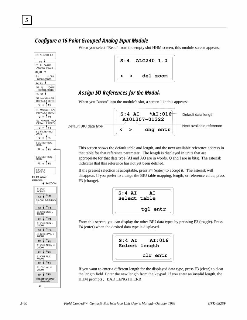
5-40 Field Control™ Genius® Bus Interface Unit User’s Manual – October 1999 GFK-0825F
5
Configure a 16-Point Grouped Analog Input ModuleWhen you select “Read” from the empty slot HHM screen, this module screen appears:
S:4 ALG240 1.0
< > del zoom
Assign I/O References for the Module
When you "zoom" into the module's slot, a screen like this appears:
Default data lengthS:4 AI *AI:016 AI01307-01322
< > chg entrDefault BIU data type Next available reference
This screen shows the default table and length, and the next available reference address inthat table for that reference parameter. The length is displayed in units that areappropriate for that data type (AI and AQ are in words, Q and I are in bits). The asteriskindicates that this reference has not yet been defined.
If the present selection is acceptable, press F4 (enter) to accept it. The asterisk willdisappear. If you prefer to change the BIU table mapping, length, or reference value, pressF3 (change).
S:4 AI AISelect table
tgl entr
From this screen, you can display the other BIU data types by pressing F3 (toggle). PressF4 (enter) when the desired data type is displayed.
S:4 AI AI:016Select length
clr entr
If you want to enter a different length for the displayed data type, press F3 (clear) to clearthe length field. Enter the new length from the keypad. If you enter an invalid length, theHHM prompts: BAD LENGTH ERR
S1 FILTERING20MS
S1 LINE FREQ60 HZ
S1: Q *Q016 Q00001-00016
S1 Module-> %IDEFAULT ZERO
S1: I * I:088 I00001-00088
S1 Module-> %AIDEFAULT ZERO
S1: ALG240: 1.1
F4S1: AI *AI016 AI00001-00016
F4, F2
F4, F2
F4, F2
F2 F1
S1 Network->%QDEFAULT ZERO
F2 F1
F2 F1
F2 F1
F1F2
S1 CH 1ACTIVE
S1 CH1 DEF RNG1
S1 CH1 SPAN L 04000
S1 CH1 ENG L 04000
S1 CH1 ENG H 20000
S1 CH1 AL H 20000
S1 CH1 SPAN H 20000
S1 CH1 AL L 04000
F1, F2 selectchannels
F2 F1
F2 F1
F2 F1
F2 F1
F2 F1
F2 F1
F2 F1
F2 F1
Repeat for otherchannels
F2
S1 CH 1CONFIG
F4 ZOOM
S1 LINE FREQ60 HZ
F1F2

GFK-0825F Chapter 5 Station Configuration 5-41
5
After “entering”the correct length, the offset (starting reference) screen appears. The BIUautomatically supplies the next available address in the selected table. You can press F4 (enter) toaccept this value, or F3 (clear) then enter a new value from the keypad. Press the F4 (enter) keyafter entering a new offset.
S:4 AI AI:016Ref Addr 01896
< > clr entr
The 16-Point Grouped Analog Input Module is an intelligent module, which uses more than onetype of data. Use the F2 ( > ) key to display the screen for the module's discrete input diagnosticdata.
S:4 I * I:088 I01817-01904
< > chg entr
You can edit this screen or accept it using the F4 (enter) key. The asterisk beside the data typedisappears, to show that the current values have been saved.
S:4 I I:088 I01817-01904
< > chg entr
Next, go to the screen that shows the module's discrete output references, which are used for faultclearing.
S:4 Q * Q:016 Q01817-01832
< > chg entr
You can also edit this screen. Use the F4 (enter key) to save the selections and continue to the nextitem. Note that all required references for the module must be entered. You can give a referenceparameter a length of zero if you do not want to map the data to the BIU. If you attempt to back outbefore the references are all configured, the HHM displays the following screen:
Cfg IncompleteClear Slot?
yes no
If you exit, the references you have configured are not saved

5-42 Field Control™ Genius® Bus Interface Unit User’s Manual – October 1999 GFK-0825F
5
Configure Data DefaultsFor data types AI and I, you can determine what the BIU should do with the module's data if theBIU loses communications with the module. Data can either be held at its present values ordefaulted to zero.
You can accept DEFAULT: ZERO with the F4 (enter) key, or press F3 (toggle) then F4 (enter) tochange to DEFAULT: HOLD and save it.
S:4 Module-> %IDEFAULT:ZERO
< > tgl entr
S:4 Module-> %IDEFAULT:HOLD
< > tgl entr
S:4 Module-> %AIDEFAULT:ZERO
< > tgl entr
For data going to the module (type Q) which is included within the BIU's I/O map, you candetermine what data the BIU will send to the module if the BIU loses communications with thenetwork.
S:4 Network-> %QDEFAULT:ZERO
< > tgl entr

GFK-0825F Chapter 5 Station Configuration 5-43
5
Configure FilteringNext, select the filtering delay to eliminate noise due to the AC power lines. Filtering increases theresponse time to changes in a channel.
The choices for filtering are:
A. 10 ms: The module averages the most recent 8 samples of the input.
B. 20 ms: The module averages the most recent 16 samples of the input.
The module will perform filtering on all inputs on the module that are configured as “active”
20MSS:4 FILTERING
< > tgl entr
1. If you want to change the displayed selection, press F3 (Tgl).
2. Use the F4 (entr) key to save the selection.
3. Press F2 ( > ) to go to the next screen.
Configure the Line FrequencyNext, set the line frequency for the module. Select 50 or 60 Hz.
Disturbances due to AC noise cause variations around the desired DC level. The amplitude ofthese variations can be reduced by configuring the rate at which the module scans inputs for theoperating frequency. If the line frequency is configured at 60 Hz, the module scans each inputchannel every 1.04 milliseconds. If the line frequency is configured at 50 Hz, the module scanseach input channel every 1.25 mS.
S:4 LINE FREQ60 HZ
< > tgl entr
1. If you want to change the displayed selection, press F3 (Tgl).
2. Use the F4 (entr) key to save the selection.
3. Press F2 ( > ) to go to the next screen.

5-44 Field Control™ Genius® Bus Interface Unit User’s Manual – October 1999 GFK-0825F
5
Circuit ConfigurationThe sequence in which circuit configuration screens appear depends on the revision level of themodule, the Hand-held Monitor and the BIU.
Channel Header
For module IC670ALG240, version 1.3 or later, if the BIU and Hand-held Monitor support displayof channel headers, a header screen appears for each channel as shown below.
S:1 CH 1 CONFIG
< > zoom
A. Press F2 (>) from this screen to go to the header screen for the next channel. Pressing F2 (>)from channel 8 displays the module's first reference parameter screen.
B. Press F1 (<) from this screen to go to the header screen for the previous channel. Pressing F1(<) from channel 1 displays the module's last reference parameter screen.
C. Press F4 (zoom) to go to the first configuration screen for the channel.
D. When in a channel-specific configuration screen, press the up arrow/MENU key to go to thatchannel's header screen.
If the BIU and Hand-held Monitor do not support display of channel headers, the header screens donot appear and keys F1 (<) and F2 (>) are used to scroll through channel-specific configurationscreens.
The following features are configured for each channel.

GFK-0825F Chapter 5 Station Configuration 5-45
5
Channel Active
When a channel is configured as Active, it is scanned for data and checked for errors. If a channelshould not be scanned, that channel can be configured as inactive. An inactive input channel returnsthe value 0.
S:4 CH 1ACTIVE
< > tgl entr
1. If you want to change the displayed selection, press F3 (Tgl).2. Use the F4 (entr) key to save the selection.3. Press F2 ( > ) to go to the next screen.
Input Range
On this screen, specify the range for the input. There are four predetermined range and data scalingcombinations (selections 1, 2, 3, and 4), plus custom scaling.
S:4 CH1 DEF RNG1
< > tgl entr
The default is 1. Selections 1 or 2 will convert the full input current span down to 0 milliamps andproduce negative values below 4 mA. Selection 1 produces engineering unit data in microAmps.These also enable an "Open Wire" diagnostic bit which is true whenever the input falls below thenormal range.
Selection Input current ( µA) = Data range
1 4000 to 20000 = 4000 to 20000
2 4000 to 20000 = 0 to 32000
3 0 to 20000 = 0 to 32000
4 0 to 24000 = 0 to 32000
(none) Configurable scaling (see below)

5-46 Field Control™ Genius® Bus Interface Unit User’s Manual – October 1999 GFK-0825F
5
Input Scaling
The following screens can be used to set up custom scaling values. The 16-Point Grouped AnalogInput Module performs its own scaling (unlike conventional Field Control analog modules, whosescaling is performed by the BIU).
Scaling can be used to define a linear relationship between a channel's input current in microAmps(µA) and the value in engineering units returned to the BIU. The default scaling configurationprovides values from 4,000 to 20,000 for an input current range of 4mA (low span value) to 20mA(high span value).
To scale a channel, choose a high and low point and enter the actual input value (span) and acorresponding engineering units value for each. During operation, the module will use these valuesto convert input currents into digital values that represent engineering units. Scaling does notincrease the resolution of the data, but it does transform the values returned to the BIU into moreconvenient units. The “Open Wire” diagnostic bit is enabled if actual input current value used forthe “Low Point” is greater than 2 milliamps.
If the scaled data falls below the minimum for engineering units, the module returns the minimumengineering units value (-32768). If the scaled data rises above the maximum for engineering units,the module returns the maximum engineering units value (32767).
The illustration below shows the module's default scaling.
24000
20000
16000
12000
8000
4000
4000 20000 24000Input Current in MicroAmps (Span)
Low Point
25000
25000
High Point
Overrange
0
Engineering Units
The first scaling screen shows the engineering units value that is considered equivalent to the lowspan (actual) value. Engineering units may be from -32768 to 32767.
S:4 CH1 EU L 00000
< > chg entr

GFK-0825F Chapter 5 Station Configuration 5-47
5
Enter the high span value for the channel. This is the actual current in microAmps to be scaled tothe high engineering units value.
S:4 CH1 EU H 32000
< > chg entr
Next, enter the actual current in microAmps to be scaled to the low engineering units value.
S:4 CH1 SPAN L 04000
< > chg entr
Span values are 16 unsigned integers ranging from 0 to 25,000. After entering the low span valuefor the input, press the F4 (enter) key. Enter a high span value for the same input.
S:4 CH1 SPAN H 20000
< > chg entr
Alarm LimitsThe next screen is used to set the low alarm limit for the channel in engineering units.
S:4 CH1 AL L 00000
< > chg entr
Each input channel can have a low alarm limit and a high alarm limit. Alarm limits can be setanywhere over the dynamic range of the signal. The range for each is -32,768 to +32,767. The highalarm limit must be greater than the low alarm limit. If alarm reporting is not wanted, alarm limitscan be set beyond the dynamic range of the signal so they will never be activated.
After entering the Low Alarm Limit, press the F4 (enter) key. Then enter the High Alarm Limit forthe channel.
S:4 CH1 AL H 32000
< > chg entr
That completes the configuration steps for one input channel on the 16-Point Grouped AnalogInput module. Continue as described above to configure the rest of the inputs.

5-48 Field Control™ Genius® Bus Interface Unit User’s Manual – October 1999 GFK-0825F
5
Configure an 8-Point Grouped Analog Voltage Input Module
When you select “Read” from the empty slot HHM screen, this module screen appears:
S : 2 AL G2 8 1 1 . 0
< > d e l z o o m
Assign I/O References for the Module
When you “zoom" into the module's slot, a screen like this appears:
Default data lengthS : 2 AI * AI : 0 0 8 AI 0 1 9 7 0 - 0 1 9 7 7
< > c h g e n t rDefault BIU data type Next available reference
This screen shows the default table and length, and the next available reference addressin that table for that reference parameter. The length is displayed in units that areappropriate for that data type (AI and AQ are in words, Q and I are in bits). The asteriskindicates that this reference has not yet been defined.
If the present selection is acceptable, press F4 (enter) to accept it. The asterisk willdisappear.
If you prefer to change the BIU table mapping, length, or reference value, press F3(change).
S : 2 AI AIS e l e c t t a b l e
t g l e n t r
From this screen, you can display the other BIU data types by pressing F3 (toggle).Press F4 (enter) when the desired data type is displayed.
S : 2 AI AI : 0 0 8S e l e c t l e n g t h
c l r e n t r
If you want to enter a different length for the displayed data type, press F3 (clear) toclear the length field. Enter the new length from the keypad. If you enter an invalidlength, the HHM prompts: BAD LENGTH ERR
S1 CH 1ACTIVE
S1 CH1 RANGE-10V to +10V
S1 CH1 SPAN LO -10000
-10000
S1 CH1 ENG HI 10000
S1 CH1 AL HI 10000
S1 CH1 SPAN HI 10000
S1 CH1 ALRM LO -10000
F4, F2
F4, F2
F2 F1
S1 Network->%QDEFAULT ZERO
F2 F1
F2 F1
F1, F2, selectchannel
F4
F2 F1
F2 F1
F2 F1
F2 F1
F2 F1
F2 F1
F2 F1
F2 F1
Repeat for otherchannels
F2
S1 FILTERING20MS
S1 LINE FREQ60 HZ
S1: Q *Q008 Q00001-00008
S1 Module-> %IDEFAULT ZERO
S1: I * I:040 I00001-00040
S1 Module-> %AIDEFAULT ZERO
S1: ALG281: 1.0
F4S1: AI *AI008 AI00001-00008
F4, F2
S1 CH1 ENG LO
S1 CH 1 CONFIG
S1 Network->%QDEFAULT ZERO

GFK-0825F Chapter 5 Station Configuration 5-49
5
After entering the correct length, the offset (starting reference) screen appears. The BIUautomatically supplies the next available address in the selected table. You can press F4 (enter) toaccept this value, or F3 (clear) then enter a new value from the keypad. Press the F4 (enter) keyafter entering a new offset.
S : 2 A I A I : 0 0 8R e f A d d r 0 0 1 1 4
< > c l r e n t r
The 8-Point Grouped Analog Voltage Input Module is an intelligent module, which uses more thanone type of data. Use the F2 ( > ) key to display the screen for the module's discrete inputdiagnostic data.
S:2 I * I:040 I01152-01191
< > chg entr
You can edit this screen or accept it using the F4 (enter) key. The asterisk beside the data typedisappears, to show that the current values have been saved.
S:2 I I:040 I01152-01191
< > chg entr
Next, go to the screen that shows the module's discrete output references, which are used for faultclearing.
S:2 Q * Q:008 Q00916-00923
< > chg entr
You can also edit this screen. Use the F4 (enter key) to save the selections and continue to the nextitem. Note that all required references for the module must be entered. You can give a referenceparameter a length of zero if you do not want to map the data to the BIU. If you attempt to back outbefore the references are all configured, the HHM displays the following screen:
Cfg IncompleteClear Slot?
yes no
If you exit, the references you have configured are not saved.

5-50 Field Control™ Genius® Bus Interface Unit User’s Manual – October 1999 GFK-0825F
5
Configure Data Defaults
For data types AI and I, you can determine what the BIU should do with the module's data if theBIU loses communications with the module. Data can either be held at its present values ordefaulted to zero.
You can accept DEFAULT: ZERO with the F4 (enter) key, or press F3 (toggle) then F4 (enter) tochange to DEFAULT: HOLD and save it.
S:2 Module-> %IDEFAULT:ZERO
< > tgl entr
S:2 Module-> %IDEFAULT:HOLD
< > tgl entr
S:2 Module-> %AIDEFAULT:ZERO
< > tgl entr
For data going to the module (type Q) which is included within the BIU's I/O map, you candetermine what data the BIU will send to the module if the BIU loses communications with thenetwork.
S:2 Network-> %QDEFAULT:ZERO
< > tgl entr

GFK-0825F Chapter 5 Station Configuration 5-51
5
Configure Filtering
Next, select the filtering delay to eliminate noise due to the AC power lines. Filtering increases theresponse time to changes in a channel.
The choices for filtering are:
A. None : The module returns the most recent sample of the input.
B. 10 ms: The module averages the most recent 8 samples of the input.
B. 20 ms: The module averages the most recent 16 samples of the input.
The module will perform filtering on all inputs on the module that are configured as "active".
20MSS:2 FILTERING
< > tgl entr
1. If you want to change the displayed selection, press F3 (tgl).
2. Use the F4 (entr) key to save the selection.
3. Press F2 ( > ) to go to the next screen.
Configure the Line Frequency
Next, set the line frequency for the module. Select 50 or 60 Hz.
Disturbances due to AC noise cause variations around the desired DC level. The amplitude ofthese variations can be reduced by configuring the rate at which the module scans inputs for theoperating frequency. If the line frequency is configured at 60 Hz, the module scans each inputchannel every 1.04 milliseconds. If the line frequency is configured at 50 Hz, the module scanseach input channel every 1.25 mS.
S:2 LINE FREQ60 HZ
< > tgl entr
1. If you want to change the displayed selection, press F3 (tgl).
2. Use the F4 (entr) key to save the selection.
3. Press F2 ( > ) to go to the first circuit configuration screen.

5-52 Field Control™ Genius® Bus Interface Unit User’s Manual – October 1999 GFK-0825F
5
Circuit Configuration
The sequence in which circuit configuration screens appear depends on the revision level of theHand-held Monitor and the BIU.
Channel Header
If the BIU and Hand-held Monitor support display of channel headers, a header screen appears foreach channel as shown below.
S:1 CH 1 CONFIG
< > zoom
A. Press F2 (>) from this screen to go to the header screen for the next channel. Pressing F2 (>)from channel 8 displays the module's first reference parameter screen.
B. Press F1 (<) from this screen to go to the header screen for the previous channel. Pressing F1(<) from channel 1 displays the module's last reference parameter screen.
C. Press F4 (zoom) to go to the first configuration screen for the channel.
D. When in a channel-specific configuration screen, press the up arrow/MENU key to go to thatchannel's header screen.
If the BIU and Hand-held Monitor do not support display of channel headers, the header screens donot appear and keys F1 (<) and F2 (>) are used to scroll through channel-specific configurationscreens.
The following features are configured for each channel.

GFK-0825F Chapter 5 Station Configuration 5-53
5
Channel Active
When a channel is configured as Active, it is scanned for data and checked for errors. If a channelshould not be scanned, that channel can be configured as inactive. An inactive input channel returnsthe value 0.
S : 2 CH 1ACT I VE
< > t g l e n t r
1. If you want to change the displayed selection, press F3 (tgl).
2. Use the F4 (entr) key to save the selection.
3. Press F2 ( > ) to go to the next screen.
Input Range
On this screen, specify the range for the input. There are two predetermined range and data scalingcombinations.
S : 2 CH1 RANGE- 1 0 V t o + 1 0 V
< > t g l e n t r
The default is -10V to +10V.
Selection Input voltage (mV) = Data range
1 -10000 to 10000 = -10000 to 10000
2 0 to 10000 = 0 to 10000

5-54 Field Control™ Genius® Bus Interface Unit User’s Manual – October 1999 GFK-0825F
5
Input Scaling
The 8-Point Grouped Analog Voltage Input Module performs its own scaling (unlike conventionalField Control analog modules, whose scaling is performed by the BIU).
Scaling can be used to define a linear relationship between a channel's input voltage in millivolts(mV) and the value in engineering units returned to the BIU. The default scaling configurationprovides values from -10,000 to 10,000 for an input voltage range of -10V (low span value) to 10V(high span value).
To scale a channel, choose a high and low point and enter the actual input value (span) and acorresponding engineering units value for each. During operation, the module will use these valuesto convert input voltages into digital values that represent engineering units. Scaling does notincrease the resolution of the data, but it does transform the values returned to the BIU into moreconvenient units.
If the scaled data falls below the minimum for engineering units, the module returns the minimumengineering units value (-32767). If the scaled data rises above the maximum for engineering units,the module returns the maximum engineering units value (32767).
The illustration below shows the module's default scaling.
The first scaling screen shows the engineering units value that is considered equivalent to the lowspan (actual) value. Engineering units may be from -32767 to 32767.
S : 2 CH1 E NG L O - 1 0 0 0 0
< > c h g e n t r
-15000
-10000
-5000
0
5000
10000
15000
-15000 -10000 -5000 0 5000 10000 15000
Input Voltage in millivolts
High Point
Low Point
10250-10250

GFK-0825F Chapter 5 Station Configuration 5-55
5
Enter the high span value for the channel. This is the actual voltage in millivolts to be scaled to thehigh engineering units value.
S : 2 CH1 E NG HI 1 0 0 0 0
< > c h g e n t r
Next, enter the actual voltage in millivolts to be scaled to the low engineering units value.
S : 2 CH1 S P AN L O - 1 0 0 0 0
< > c h g e n t r
Span values are 8 signed integers ranging from -10,000 to 10,000. After entering the low spanvalue for the input, press the F4 (enter) key. Enter a high span value for the same input.
S : 2 CH1 S P AN HI - 1 0 0 0 0
< > c h g e n t r
Alarm Limits
The next screen is used to set the low alarm limit for the channel in engineering units.
S : 2 CH1 AL RM L O - 1 0 0 0 0
< > c h g e n t r
Each input channel can have a low alarm limit and a high alarm limit. Alarm limits can be setanywhere over the dynamic range of the signal. The range for each is -32,767 to +32,767. The highalarm limit must be greater than the low alarm limit. If alarm reporting is not wanted, alarm limitscan be set beyond the dynamic range of the signal so they will never be activated.
After entering the Low Alarm Limit, press the F4 (enter) key. Then enter the High Alarm Limit forthe channel.
S : 2 CH1 AL RM HI 1 0 0 0 0
< > c h g e n t r
That completes the configuration steps for one input channel on the 8-Point Grouped AnalogVoltage Input module. Continue as described above to configure the rest of the inputs.
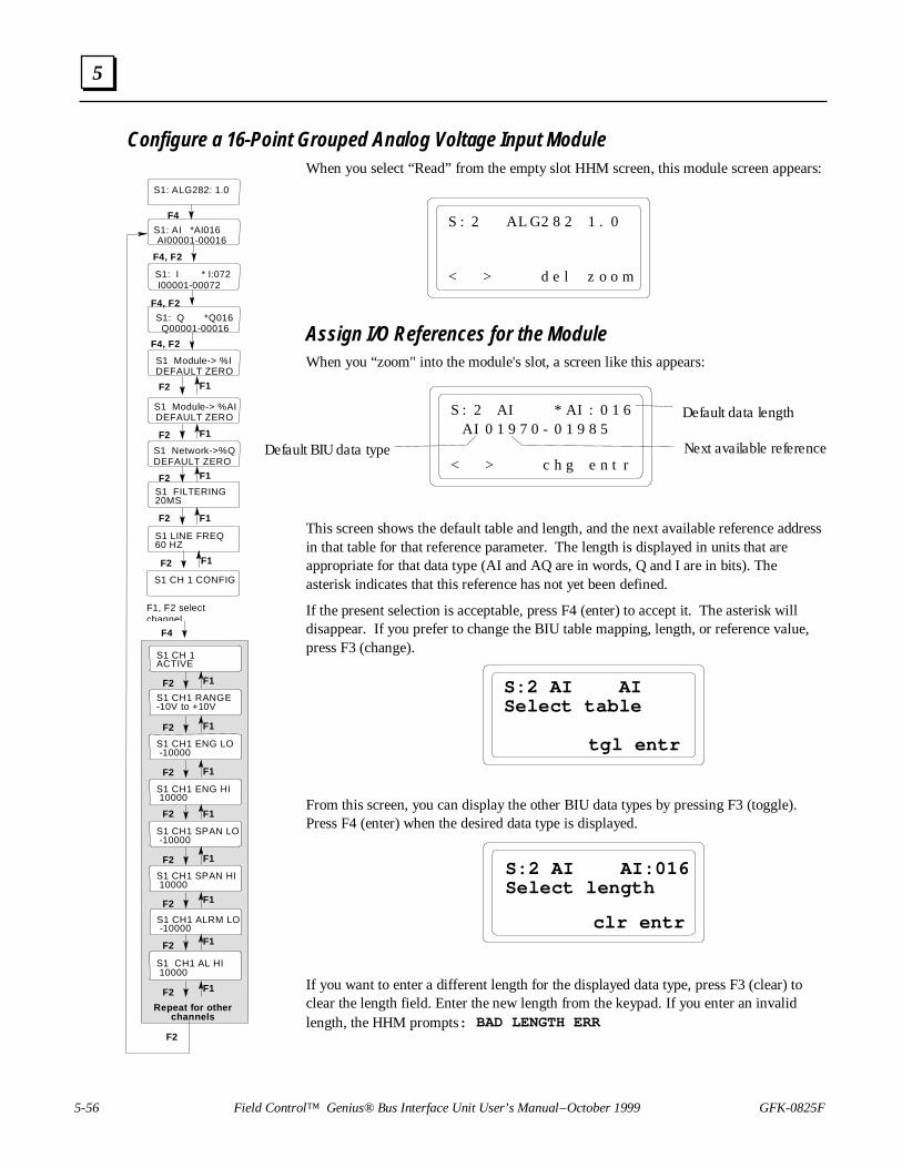
5-56 Field Control™ Genius® Bus Interface Unit User’s Manual – October 1999 GFK-0825F
5
Configure a 16-Point Grouped Analog Voltage Input ModuleWhen you select “Read” from the empty slot HHM screen, this module screen appears:
S : 2 AL G2 8 2 1 . 0
< > d e l z o o m
Assign I/O References for the ModuleWhen you “zoom" into the module's slot, a screen like this appears:
Default data lengthS : 2 AI * AI : 0 1 6 AI 0 1 9 7 0 - 0 1 9 8 5
< > c h g e n t rDefault BIU data type Next available reference
This screen shows the default table and length, and the next available reference addressin that table for that reference parameter. The length is displayed in units that areappropriate for that data type (AI and AQ are in words, Q and I are in bits). Theasterisk indicates that this reference has not yet been defined.
If the present selection is acceptable, press F4 (enter) to accept it. The asterisk willdisappear. If you prefer to change the BIU table mapping, length, or reference value,press F3 (change).
S:2 AI AISelect table
tgl entr
From this screen, you can display the other BIU data types by pressing F3 (toggle).Press F4 (enter) when the desired data type is displayed.
S:2 AI AI:016Select length
clr entr
If you want to enter a different length for the displayed data type, press F3 (clear) toclear the length field. Enter the new length from the keypad. If you enter an invalidlength, the HHM prompts: BAD LENGTH ERR
S1 CH 1ACTIVE
S1 CH1 RANGE-10V to +10V
S1 CH1 SPAN LO -10000
-10000
S1 CH1 ENG HI 10000
S1 CH1 AL HI 10000
S1 CH1 SPAN HI 10000
S1 CH1 ALRM LO -10000
F4
F2 F1
F2 F1
F2 F1
F2 F1
F2 F1
F2 F1
F2 F1
F2 F1
Repeat for otherchannels
F2
S1 FILTERING20MS
S1 LINE FREQ60 HZ
S1: Q *Q016 Q00001-00016
S1 Module-> %IDEFAULT ZERO
S1: I * I:072 I00001-00072
S1 Module-> %AIDEFAULT ZERO
S1: ALG282: 1.0
F4
S1: AI *AI016 AI00001-00016
F4, F2
S1 CH1 ENG LO
F4, F2
F4, F2
F2 F1
S1 Network->%QDEFAULT ZERO
F2 F1
F2 F1
F2 F1
S1 CH 1 CONFIG
F1, F2 selectchannel
F2 F1

GFK-0825F Chapter 5 Station Configuration 5-57
5
After entering the correct length, the offset (starting reference) screen appears. The BIUautomatically supplies the next available address in the selected table. You can press F4 (enter) toaccept this value, or F3 (clear) then enter a new value from the keypad. Press the F4 (enter) keyafter entering a new offset.
S:2 AI AI:016Ref Addr 00114
< > clr entr
The 16-Point Grouped Analog Voltage Input Module is an intelligent module, which uses morethan one type of data. Use the F2 ( > ) key to display the screen for the module's discrete inputdiagnostic data.
S:2 I * I:072 I01152-01223
< > chg entr
You can edit this screen or accept it using the F4 (enter) key. The asterisk beside the data typedisappears, to show that the current values have been saved.
S:2 I I:072 I01152-01223
< > chg entr
Next, go to the screen that shows the module's discrete output references, which are used for faultclearing.
S:2 Q * Q:016 Q00916-00931
< > chg entr
You can also edit this screen. Use the F4 (enter key) to save the selections and continue to the nextitem. Note that all required references for the module must be entered. You can give a referenceparameter a length of zero if you do not want to map the data to the BIU. If you attempt to back outbefore the references are all configured, the HHM displays the following screen:
Cfg IncompleteClear Slot?
yes no
If you exit, the references you have configured are not saved

5-58 Field Control™ Genius® Bus Interface Unit User’s Manual – October 1999 GFK-0825F
5
Configure Data Defaults
For data types AI and I, you can determine what the BIU should do with the module's data if theBIU loses communications with the module. Data can either be held at its present values ordefaulted to zero.
You can accept DEFAULT: ZERO with the F4 (enter) key, or press F3 (toggle) then F4 (enter) tochange to DEFAULT: HOLD and save it.
S:2 Module-> %IDEFAULT:ZERO
< > tgl entr
S:2 Module-> %IDEFAULT:HOLD
< > tgl entr
S:2 Module-> %AIDEFAULT:ZERO
< > tgl entr
For data going to the module (type Q) which is included within the BIU's I/O map, you candetermine what data the BIU will send to the module if the BIU loses communications with thenetwork.
S:2 Network-> %QDEFAULT:ZERO
< > tgl entr

GFK-0825F Chapter 5 Station Configuration 5-59
5
Configure Filtering
Next, select the filtering delay to eliminate noise due to the AC power lines. Filtering increases theresponse time to changes in a channel.
The choices for filtering are:
A. None : The module returns the most recent sample of the input.
B. 10 ms: The module averages the most recent 8 samples of the input.
B. 20 ms: The module averages the most recent 16 samples of the input.
The module will perform filtering on all inputs on the module that are configured as "active".
20MSS:2 FILTERING
< > tgl entr
1. If you want to change the displayed selection, press F3 (tgl).
2. Use the F4 (entr) key to save the selection.
3. Press F2 ( > ) to go to the next screen.
Configure the Line Frequency
Next, set the line frequency for the module. Select 50 or 60 Hz.
Disturbances due to AC noise cause variations around the desired DC level. The amplitude ofthese variations can be reduced by configuring the rate at which the module scans inputs for theoperating frequency. If the line frequency is configured at 60 Hz, the module scans each inputchannel every 1.04 milliseconds. If the line frequency is configured at 50 Hz, the module scanseach input channel every 1.25 mS.
S:2 LINE FREQ60 HZ
< > tgl entr
1. If you want to change the displayed selection, press F3 (tgl).
2. Use the F4 (entr) key to save the selection.
3. Press F2 ( > ) to go to the first circuit configuration screen.

5-60 Field Control™ Genius® Bus Interface Unit User’s Manual – October 1999 GFK-0825F
5
Circuit ConfigurationThe sequence in which circuit configuration screens appear depends on the revision level of theHand-held Monitor and the BIU.
Channel Header
If the BIU and Hand-held Monitor support display of channel headers, a header screen appears foreach channel as shown below.
S:1 CH 1 CONFIG
< > zoom
A. Press F2 (>) from this screen to go to the header screen for the next channel. Pressing F2 (>)from channel 8 displays the module's first reference parameter screen.
B. Press F1 (<) from this screen to go to the header screen for the previous channel. Pressing F1(<) from channel 1 displays the module's last reference parameter screen.
C. Press F4 (zoom) to go to the first configuration screen for the channel.
D. When in a channel-specific configuration screen, press the up arrow/MENU key to go to thatchannel's header screen.
If the BIU and Hand-held Monitor do not support display of channel headers, the header screens donot appear and keys F1 (<) and F2 (>) are used to scroll through channel-specific configurationscreens.
The following features are configured for each channel.
Channel Active
When a channel is configured as Active, it is scanned for data and checked for errors. If a channelshould not be scanned, that channel can be configured as inactive. An inactive input channel returnsthe value 0.
S:2 CH 1ACTIVE
< > tgl entr
1. If you want to change the displayed selection, press F3 (tgl).
2. Use the F4 (entr) key to save the selection.
3. Press F2 ( > ) to go to the next screen.

GFK-0825F Chapter 5 Station Configuration 5-61
5
Input Range
On this screen, specify the range for the input. There are two predetermined range and data scalingcombinations.
S:2 CH1 RANGE-10V to +10V
< > tgl entr
The default is -10V to +10V.
Selection Input voltage (mV) = Data range
1 -10000 to 10000 = -10000 to 10000
2 0 to 10000 = 0 to 10000

5-62 Field Control™ Genius® Bus Interface Unit User’s Manual – October 1999 GFK-0825F
5
Input Scaling
The 16-Point Grouped Analog Voltage Input Module performs its own scaling (unlike conventionalField Control analog modules, whose scaling is performed by the BIU).
Scaling can be used to define a linear relationship between a channel's input voltage in millivolts(mV) and the value in engineering units returned to the BIU. The default scaling configurationprovides values from -10,000 to 10,000 for an input voltage range of -10V (low span value) to 10V(high span value).
To scale a channel, choose a high and low point and enter the actual input value (span) and acorresponding engineering units value for each. During operation, the module will use these valuesto convert input voltages into digital values that represent engineering units. Scaling does notincrease the resolution of the data, but it does transform the values returned to the BIU into moreconvenient units.
If the scaled data falls below the minimum for engineering units, the module returns the minimumengineering units value (-32767). If the scaled data rises above the maximum for engineering units,the module returns the maximum engineering units value (32767).
The illustration below shows the module's default scaling.
The first scaling screen shows the engineering units value that is considered equivalent to the lowspan (actual) value. Engineering units may be from -32767 to 32767.
S:2 CH1 ENG LO -10000
< > chg entr
-15000
-10000
-5000
0
5000
10000
15000
-15000 -10000 -5000 0 5000 10000 15000
Input Voltage in millivolts
High Point
Low Point
10250-10250

GFK-0825F Chapter 5 Station Configuration 5-63
5
Enter the high span value for the channel. This is the actual voltage in millivolts to be scaled to thehigh engineering units value.
S : 2 CH1 E NG HI 1 0 0 0 0
< > c h g e n t r
Next, enter the actual voltage in millivolts to be scaled to the low engineering units value.
S : 2 CH1 S P AN L O - 1 0 0 0 0
< > c h g e n t r
Span values are 16 signed integers ranging from -10,000 to 10,000. After entering the low spanvalue for the input, press the F4 (enter) key. Enter a high span value for the same input.
S : 2 CH1 S P AN HI - 1 0 0 0 0
< > c h g e n t r
Alarm Limits
The next screen is used to set the low alarm limit for the channel in engineering units.
S : 2 CH1 AL RM L O - 1 0 0 0 0
< > c h g e n t r
Each input channel can have a low alarm limit and a high alarm limit. Alarm limits can be setanywhere over the dynamic range of the signal. The range for each is -32,767 to +32,767. The highalarm limit must be greater than the low alarm limit. If alarm reporting is not wanted, alarm limitscan be set beyond the dynamic range of the signal so they will never be activated.
After entering the Low Alarm Limit, press the F4 (enter) key. Then enter the High Alarm Limit forthe channel.
S : 2 CH1 AL RM HI 1 0 0 0 0
< > c h g e n t r
That completes the configuration steps for one input channel on the 16-Point Grouped AnalogVoltage Input module. Continue as described above to configure the rest of the inputs.

5-64 Field Control™ Genius® Bus Interface Unit User’s Manual – October 1999 GFK-0825F
5
Configure an RTD Input Module When you select “Read” from the empty slot HHM screen, this module screen appears:
S:4 ALG620 *.*
< > del zoom
Module version
Assign I/O References for the Module
Press F4 to zoom into the slot. A screen like this appears:
Number of references for this module type
S:4 AI *AI:004 AI01311-01314
< > chg entr
This screen shows the default table and length and the next available reference addressfor that reference type. The length is displayed in appropriate units (AI and AQ inwords, Q and I are bits). An asterisk indicates that the reference is not yet defined. If thepresent selection is acceptable, press F4 (enter) to accept it. The asterisk will disappear.
If you prefer to change the BIU table mapping, length, or reference value, press F3(change).
S:4 AI AISelect table
chg entr
From this screen, you can display the other data types by pressing F3 (toggle). Press F4(enter) when the desired data type is displayed.
S:4 AI AI:004Select length
chg entr
If you want to enter a different length for the displayed data type, press F3 (clear) toclear the length field. Enter the new length from the keypad. If you enter an invalidlength, the HHM prompts: BAD LENGTH ERR After “entering” the correct length, theoffset (starting reference) screen appears. The BIU automatically supplies the nextavailable address in the selected table.
S1 CH 1ACTIVE
S1 CH1 UNITSDEG C
S1 CH1 ALARM HI 00800
S1CH1RTDTYPE100 PT 385
S1CH1WIRETYP 3 WIRE
S1 RESIST.1 00000
S1 CH1 ALARM LO
-00200
F2 F1
F2 F1
F2 F1
F2 F1
F2 F1
F2 F1
F2 F1
Repeat forOther Channels
F2
S1 LINE FREQ60 HZ
S1: Q *Q:08 Q00001-00008
S1 AQ *AQ:004AQ00001-00004
S1: I *I:032 I00001-00032
S1 Network->%QDEFAULT ZERO
S1 Module-> %IDEFAULT ZERO
S1: ALG620
F4
S1: AI *AI004 AI00001-00004
F4, F2
F4, F2
F4, F2
F4, F2 F1
S1 Module-> %AIDEFAULT ZERO
F2 F1
F2 F1
F2 F1
F2 F1
F1, F2 selectchannels
F4
S1 CH 1 CONFIG

GFK-0825F Chapter 5 Station Configuration 5-65
5
You can press F4 (enter) to accept this value, or F3 (clear) then enter a new value from the keypad.Press the F4 (enter) key after entering a new offset.
S:4 AI AI:004Ref Addr 01896
clr entr
Use the F2 ( > ) key to display the screen for the module's discrete input diagnostic data.
S:4 I * I:032 I01817-01904
< > chg entr
You can edit this screen or accept it using the F4 (enter) key. After you press the Enter key, theasterisk disappears to show that the current values have been saved. Next, press F2 to go to thescreen that shows the module's Q references, which are for fault clearing.
S:4 Q * Q:008 Q01817-01832
< > chg entr
You can also edit this screen. Use the F4 (enter key) to save the selections. Press F2 to continue tothe next item. The next screen displays AQ references for the module. Enter a length of 0. Usethe F4 (enter) key to save and continue.
S:4 AQ AQ:004 AQ01057-01060
< > chg entr
All required references for the module must be entered. You can give a reference parameter alength of zero if you do not want to map the data to the BIU. If you attempt to back out before thereferences are all configured, the HHM displays the following screen:
Cfg IncompleteClear Slot?
yes no
If you exit from this display, the references you have configured are not saved.

5-66 Field Control™ Genius® Bus Interface Unit User’s Manual – October 1999 GFK-0825F
5
Assign Data Defaults
For data types AI and I, you can determine what the BIU should do with the module's data if theBIU loses communications with the module. Data can either be held at its present values ordefaulted to zero.
You can accept DEFAULT: ZERO with the F4 (enter) key, or press F3 (toggle) then F4 (enter) tochange to DEFAULT: HOLD and save it.
I data is diagnostic data sent by the module.
S:4 Module-> %IDEFAULT:ZERO
< > tgl entr
AI data is RTD input data sent by the module.
S:4 Module-> %AIDEFAULT:ZERO
< > tgl entr
For command data going to the module (data types Q and AQ) which is included within the BIU'sI/O map, you can determine what data the BIU will send to the module if the BIU losescommunications with the network.
S:4 Network-> %QDEFAULT:ZERO
< > tgl entr
Line Frequency
Next, set the line frequency for the module. Select 50 or 60 Hz.
S:1 LINE FREQ60 HZ
< > tgl entr

GFK-0825F Chapter 5 Station Configuration 5-67
5
Circuit ConfigurationThe sequence in which circuit configuration screens appear depends on the revision level of themodule, the Hand-held Monitor and the BIU.
Channel Header
For module version IC670ALG620, version 1.4 or later, if the BIU and Hand-held Monitor supportdisplay of channel headers, a header screen appears for each channel as shown below.
S:1 CH 1 CONFIG
< > zoom
A. Press F2 (>) from this screen to go to the header screen for the next channel. Pressing F2 (>)from channel 8 displays the module's first reference parameter screen.
B. Press F1 (<) from this screen to go to the header screen for the previous channel. Pressing F1(<) from channel 1 displays the module's last reference parameter screen.
C. Press F4 (zoom) to go to the first configuration screen for the channel.
D. When in a channel-specific configuration screen, press the up arrow/MENU key to go to thatchannel's header screen.
If the BIU and Hand-held Monitor do not support display of channel headers, the header screens donot appear and keys F1 (<) and F2 (>) are used to scroll through channel-specific configurationscreens.
The following features are configured for each channel.

5-68 Field Control™ Genius® Bus Interface Unit User’s Manual – October 1999 GFK-0825F
5
Channel Active
S:4 CH 1ACTIVE
< > tgl entr
When a channel is configured as Active, it is scanned for data and checked for errors. If a channelshould not be scanned, that channel can be configured as inactive. An inactive input channel returnsthe value 0.
1. If you want to change the displayed selection, press F3 (Tgl).2. Use the F4 (entr) key to save the selection.3. Press F2 ( > ) to go to the next screen.
Units
Next, select the conversion type for each RTD: tenths of degrees Fahrenheit, tenths of degreesCelsius, or tenths of Ohms.
S:1 CH1 UNITSDEG C
< > tgl entr
1. Press F3 (toggle) if you want to change the displayed type of units.
2. Use the F4 (enter) key to save the selections on this screen and go on to the next item.
Units' Ranges
The following table shows the ranges for the types of units configured on this screen. Notice thatTenths of Ohms units are unsigned.
Units Selected Integer Ranges Engineering Units Ranges
(Tenths of) Degrees (F or C) -32767 to +32767 -3276.7deg. to +3276.7deg.
(Tenths of) Ohms 0 to 65535 0 Ohms to 6553.5 Ohms

GFK-0825F Chapter 5 Station Configuration 5-69
5
RTD TypeSelect the RTD type that most closely matches the RTD used on that channel. The table below hasmore information about RTD categories.
S:1 CH1 RTD TYPE100 PT 385
< > tgl entr
1. Use the F3 (toggle) key if you want to change the displayed RTD type.
2. Use the F4 (enter) key to save the selections on this screen and go on to the next item.
Selection Comments Selection Comments Selection Comments
10 PT 10 Ohm Platinum (PT) 100 PT 3916 100 Ohm Platinum,alpha =.003916
100 NI 618 100 Ohm Nickel At 0 deg. C,DIN43760, alpha =.00618
25 PT 25 Ohm Platinum IPTS-68 1K PT 375 1 KOhm Platinum,alpha =.00375
120 NI 672 120 Ohm Nickel, at 0 deg. C,alpha =.00672
25.5 PT 392 25.5 Ohm Platinum, alpha=.00392 at 0 deg. C Lab Std
10 CU 10 Ohm Copper, at25deg. C, IPTS-68
604 NI/FE 518 604 Ohm Nickel/Iron, at0deg. C, alpha =.00518
100 PT 385 100 Ohm Platinum,DIN43760, alpha =.00385
9.035 CU 427 9.035 Ohm Copper, at25deg. C, alpha =.00427
IK NI/FE 527 1 KOhm Nickel/Iron, at70deg. F, alpha =.00527
100 PT 3902 100 Ohm Platinum, alpha=.003902
50 CU 427 50 Ohm Copper, alpha =.00427
500 OHM Select UNITS of 1/10 Ohms
100 PT 392 100 Ohm Platinum,alpha=.00392 IPTS-6 8
100 CU 427 100 Ohm Copper,alpha =.00427
3000 OHM Select UNITS of 1/10 Ohms
100PT 3923 98.13 Ohm Platinum, alpha=.003923
100 NI 100 Ohm Nickel,IPTS-68
Wire Type
Next, specify the type of field wiring present at the terminal board connectors for each RTD. Thechoices are 3 WIRE and 4 WIRE.
S:1 CH1 WIRE TYP3 WIRE
< > tgl entr
1. Use the F3 (toggle) key if you want to change the displayed RTD Wire type.
2. Use the F4 (enter) key to save the selections on this screen and go on to the next item.

5-70 Field Control™ Genius® Bus Interface Unit User’s Manual – October 1999 GFK-0825F
5
Low Alarm Limit
Next, set the low alarm limit for the RTD. The range is -32,767 to +32,767.
Each RTD channel can have a low alarm limit and a high alarm limit. Alarms do not stop theprocess or change the value of the input.
Alarm limits can be set anywhere over the dynamic range of the signal. If alarm reporting is notwanted, alarm limits can be set beyond the dynamic range of the signal so they will never beactivated.
The units used for alarm limits are the same type entered on the Units screen (tenths of Ohms, ortenths of degrees Celsius or Fahrenheit). If units are subsequently changed, alarm limits should bereviewed and adjusted if necessary.
S:1 CH1 ALARM LO-200
< > chg entr
1. Use the F3 (change) key if you want to change the Low Alarm Limit, and enter the new value.
2. Use the F4 (enter) key to save the selections on this screen and go on to the next item.
High Alarm Limit
Next, set the high alarm limit for an RTD. The range is -32,767 to +32,767. The high alarm limitmust be greater than the low alarm limit.
S:1 CH1 ALARM HI800
< > chg entr
1. Use the F3 (change) key if you want to change the High Alarm Limit, and enter the new value.
2. Use the F4 (enter) key to save the selections on this screen and go on to the next item.

GFK-0825F Chapter 5 Station Configuration 5-71
5
Resistance
The RTD Resistance is a resistance adjustment that can change the Ohms value of an input. Its useis optional. The range is 0 to 3276.7.
The value is entered and displayed in tenths of Ohms.
S:1 RESIST.1 00000
< > chg entr
Tenths of Ohms
The resistance value is used to correct for RTD values that are not at the nominal value. Forexample, if a 100 Ohm platinum RTD is being used and it measures 99 Ohms at 25°C instead ofthe nominal 100 Ohms at 25°C, the value 990 should be entered here to correct the temperaturereadings.
1. Use the F3 (change) key if you want to change the RTD Resistance.
2. Enter the new value in tenths of ohms.
3. Use the F4 (enter) key to save the selections on this screen and go on to the next channel.
RTD Resistance specifications are available from the RTD manufacturer, or may be determined byactual measurement.
RTD Type Low ΩLimit
High ΩLimit
LowTemp. Deg.
C
High Temp.Deg. C
10 Ohm Copper @ 25°C 6.13600 14.8200 -75.00 150.00
10 Ohm Platinum @ 25°C 7.02000 37.2599 -70.00 1000.00
25 Ohm Platinum 4.14500 74.3089 -201.1111 537.77
100 Ohm Nickel 80.88890 147.7700 -40.00 140.00
1 KOhm Platinum, α=.00375 199.4880 2754.620 -200.00 500.00
100 Ohm Platinum α=.00385 27.01 389.936 -180.0 850.0
100 Ohm Platinum, α=.003902 93.5400 135.000 -17.7777 99.9999
100 Ohm Platinum IPTS68 (PA) 26.5 327.744 -200.0 630.0
100 Ohm Platinum SAMA-RC21-4 (PC) 26.5 311.874 -200.0 600.0
100 Ohm Platinum JISC-1604-'81 26.5 323.780 -200.0 620.0
25.5 Ohm Platinum Lab Std (PJ) 4.50 83.575 -200.0 630.0
9.035 Ohm Copper (CA) 6.05 16.400 -100.0 260.0
50 Ohm Copper (CB/2) 28.379 105.787 -100.0 260.0
100 Ohm Copper (CB) 56.757 211.574 -100.0 260.0
100 Ohm Nickel (NB) 69.520 223.221 -60.0 180.0
120 Ohm Nickel (NA) 66.600 380.310 -80.0 260.0
604 Ohm Nickel/Iron (FA) 372.789 1318.722 -100.0 204.0
1 KOhm Nickel/Iron (FB) 566.576 1985.891 -100.0 204.0

5-72 Field Control™ Genius® Bus Interface Unit User’s Manual – October 1999 GFK-0825F
5
Configuring a Thermocouple Input Module When you select “Read” from the empty slot HHM screen, this module screen appears:
S:4 ALG630 *.*
< > del zoom
Assign I/O References for the Module
Press F4 to zoom into the slot. A screen like this appears:
Number of references for this module type
S:4 AI *AI:008 AI00009-00016
< > chg entr
This screen shows the default table and length and the next available reference address forthat reference type. The length is displayed in appropriate units (AI and AQ in words, Qand I are bits). The asterisk indicates that the reference is not yet defined. If the presentselection is acceptable, press F4 (enter) to accept it. The asterisk will disappear.
If you prefer to change the BIU table mapping, length, or reference value, press F3(change).
S:4 AI AISelect table
tgl entr
From this screen, you can display the other data types by pressing F3 (toggle). Press F4(enter) when the desired data type is displayed.
S:4 AI AI:008Select length
clr entr
If you want to enter a different length for the displayed data type, press F3 (clear) to clearthe length field. Enter the new length from the keypad. If you enter an invalid length, theHHM prompts: BAD LENGTH ERR After “entering” the correct length, the offset(starting reference) screen appears. The BIU automatically supplies the next availableaddress in the selected table.
F2
S1 CH1ACTIVE
S1 CH1 ALARM HI01400
S1 CH1 TC TYPENONE
S1 CH1 RJ TYPELOCAL
S1 CH1 RJVAL.01 00000
S1 CH1 UNITSMV
S1 CH1 RANGE TP 625
S1 CH1 ALARM LO-00250
S1 CH1 OFFST.01
00000
F2 F1
F2 F1
F2 F1
F2 F1
F2 F1
F2 F1
F2 F1
F2 F1
F2 F1
F2 F1
Repeat forOther
S1 LINE FREQ60 HZ
S1 OTC SUPPRESSNO
S1: AI AI:008AI00001-00008
S1 Module-> %IDEFAULT ZERO
S1: ALG630
F4
S1: I *I:048 I00001-00032
S1: AI *AI008 AI00001-00008
F4, F2
S1: Q Q:016 Q00001-00016
F4, F2
F4, F2
F2 F1
S1 AQ *AQ:008AQ00001-00004
F2 F1
S1 Module-> %AIDEFAULT ZERO
F2 F1
F2 F1
F2 F1
NETWORK->%AQDEFAULT ZERO
F2 F1NETWORK->%QDEFAULT ZERO
F2 F1

GFK-0825F Chapter 5 Station Configuration 5-73
5
You can press F4 (enter) to accept this value, or F3 (clear) then enter a new value from the keypad.Press the F4 (enter) key after entering a new offset.
S: 4 AI AI : 0 0 8Re f Ad d r 0 1 8 9 6
c l r e n t r
Use the F2 ( > ) key to display the screen for the module's discrete input diagnostic data.
S: 4 I * I : 0 4 8I 0 1 8 0 1 - 0 1 8 4 8
< > c h g e n t r
You can edit this screen or accept it using the F4 (enter) key. After you press the Enter key, theasterisk disappears to show that the current values have been saved. Next, go to the screen thatshows the module's Q references, which are for fault clearing.
S:4 Q * Q:016 Q01801-01816
< > chg entr
You can also edit this screen. Use the F4 (enter key) to save the selections and continue to the nextitem. The next screen displays the AQ reference for the module. You can edit the address andlength. This one-word reference is used only if a remote compensation value will be supplied to themodule by the BIU. ("Remote" must be configured as the RJ Type). For all other RJ Types, enter alength of 0. Use the F4 (enter) key to save and continue.
S:4 AQ AQ:001 AQ01057-01058
< > chg entr
All required references for the module must be entered. You can give a reference parameter alength of zero if you do not want to map the data to the BIU. If you attempt to back out before thereferences are all configured, the HHM displays the following screen:
Cfg IncompleteClear Slot?
yes no
If you exit from this display, the references you have configured are not saved

5-74 Field Control™ Genius® Bus Interface Unit User’s Manual – October 1999 GFK-0825F
5
Assign Data Defaults
For input data types AI and I, you can determine what the BIU should do with the module's data ifthe BIU loses communications with the module. Data can either be held at its present values ordefaulted to zero.
You can accept DEFAULT: ZERO with the F4 (enter) key, or press F3 (toggle) then F4 (enter) tochange to DEFAULT: HOLD and save it.
Discrete input (I) data is diagnostic data sent by the module.
S:4 Module-> %IDEFAULT:ZERO
< > tgl entr
Analog input (AI) data is input data sent by the module.
S:4 Module-> %AIDEFAULT:ZERO
< > tgl entr
For command data going to the module (data types Q and AQ) which is included within the BIU'sI/O map, you can determine what data the BIU will send to the module if the BIU losescommunications with the network.
S:4 Network-> %QDEFAULT:ZERO
< > tgl entr
S:4 Network->%AQDEFAULT:ZERO
< > tgl entr

GFK-0825F Chapter 5 Station Configuration 5-75
5
Line Frequency
Next, set the line frequency for the module. Select 50 or 60 Hz.
S:1 LINE FREQ60 HZ
< > tgl entr
Suppress Open Thermocouple Diagnostic
S:4 OTC SUPPRESSNO
< > tgl entr
Configure whether the module should perform Open Thermocouple diagnostics on the input data.
1. Select NO (the default) if the module should perform Open Thermocouple diagnostics. SelectYES if it should not.
2. Use the F4 (enter) key to save the selections on this screen and go on to the next item.

5-76 Field Control™ Genius® Bus Interface Unit User’s Manual – October 1999 GFK-0825F
5
Circuit Configuration
The following features are configured for each channel in turn.
Channel Active
S:4 CH 1ACTIVE
< > tgl entr
When a channel is configured as Active, it is scanned for data and checked for errors. If a channelshould not be scanned, that channel can be configured as inactive. An inactive input channel returnsthe value 0.
1. If you want to change the displayed selection, press F3 (Tgl).2. Use the F4 (entr) key to save the selection.3. Press F2 ( > ) to go to the next screen.
Engineering Units
Specify whether the module should report values for the input as hundredths of millivolts, or astenths of degrees C or F.
S:1 CH1 UNITSMV
< > tgl entr
1. Use the F3 (tgl) key if you want to change the current choice.2. Use the F4 (enter) key to save the selection.

GFK-0825F Chapter 5 Station Configuration 5-77
5
Thermocouple Type
Next, specify the type of Thermocouple present on the channel: J, K, T, E, S, R, B, N, G, C, D, orPlatinel II. The default is NONE. If this default is selected, the module will report inputs asmillivolts.
S:1 CH1 TC TYPENONE
< > tgl entr
Note: If you selected Engineering Units of millivolts on the previous screen, the TC Type shouldbe NONE.
1. Use the F3 (toggle) key if you want to change the displayed thermocouple type.2. Use the F4 (enter) key to save the selection.
TC Type Low mV Limit High mV Limit Low TemperatureLimit (C)
High TemperatureLimit (C)
J -8.0960 57.9420 -210.00 1000.00
K -5.8910 54.8069 -200.00 1370.00
T -5.6030 20.2520 -200.00 390.00
E -8.8240 76.3580 -200.00 1000.00
S -0.1940 18.5040 -40.00 1750.00
R -0.1880 20.8780 -40.00 1750.00
B 0.03300 13.8140 100.00 1820.00
N -0.57480 47.5019 -22.222 1300.00
G -0.00600 38.5639 4.444 2315.55
C 0.23400 37.0660 -17.7777 2315.55
D -0.16300 39.5060 -17.7777 2315.55
Platinel II 0.0000 52.25 0.00 1300.00
Range Type
If None was configured for Thermocouple Type, specify the range for millivolt inputs. The numberdisplayed represents a +/- span of millivolts. For example, 19.5 represents +/-19.53 millivolts. Thechoices are: unused, 19.5mV, 39mV, 78.125mV, 156.25mV, 312.5mV, and 625mV. The default is625.
S:1 CH1 RANGE TP625
< > tgl entr
1. Use the F3 (toggle) key if you want to change the displayed thermocouple range.
2. Use the F4 (enter) key to save the selection and go on to the next item.
Note: If you selected Engineering Units of millivolts, be sure to configure alarm limits (see nextpage) within the Range selected here.

5-78 Field Control™ Genius® Bus Interface Unit User’s Manual – October 1999 GFK-0825F
5
Low Alarm Limit
Next, set the low alarm limit for the input. The range is -32,767 to +32,767.
Each thermocouple channel can have a low alarm limit and a high alarm limit. If an input reachesone of its limits, the module reports the actual value and a LOW ALARM or HIGH ALARMmessage. The message identifies the circuit in alarm. Only one message is sent upon reaching thelimit. Alarms do not stop the process or change the value of the input.
Alarm limits can be set anywhere over the dynamic range of the signal. If alarm reporting is notwanted, alarm limits can be set beyond the dynamic range of the signal so they will never beactivated.
The units used for alarm limits are the same type entered on the Units screen (hundredths ofmillivolts or tenths of degrees Celsius or Fahrenheit). If units are subsequently changed, alarmlimits should be reviewed and adjusted if necessary.
S:1 CH1 ALARM LO-00250
< > chg entr
1. Use the F3 (change) key if you want to change the Low Alarm Limit, and enter the new value.
2. Use the F4 (enter) key to save the selections on this screen and go on to the next item.
High Alarm Limit
Next, set the high alarm limit for a thermocouple. The range is -32,767 to +32,767. The high alarmlimit must be greater than the low alarm limit.
S:1 CH1 ALARM HI01400
< > chg entr
1. Use the F3 (change) key if you want to change the High Alarm Limit, and enter the new value.
2. Use the F4 (enter) key to save the selections on this screen and go on to the next item.

GFK-0825F Chapter 5 Station Configuration 5-79
5
Reference Junction Compensation
Specify how or whether the channel will perform cold junction compensation. The choices areLocal, Remote, Fixed, and None. The default is Local.
S:1 CH1 RJ TYPELOCAL
< > tgl entr
Select Local if cold junction compensation will be provided for locally-terminated thermocouplesusing a locally-mounted thermistor (either as part of a Thermocouple Terminal Block (catalognumber IC670CHS004), as described in the Installation Instructions, or connected directly to the Aand B terminals of the I/O Terminal Block on which the module is installed).
Select Remote if the module will receive a cold junction compensation value from the controller,via the BIU, as analog output (AQ) data. The value is in degrees C, and includes 2 decimal places.
Select Fixed if you want to configure a specific reference value (on a later screen). The fixed valueis configurable on a per channel basis.
Select None for measuring millivolt inputs or if cold junction will be maintained at zero degrees C.
1. Use the F3 (toggle) key if you want to change the displayed Reference Junction type.
2. Use the F4 (enter) key to save the selection and go on to the next item.
Reference Junction Value
If you selected Fixed for RJ (Reference Junction) Type, enter the fixed value here. The .01 in thedisplay is a reminder that the value entered includes tenths and hundredths. For example, youwould enter 5522 to specify a value of 55.22 millivolts. The fixed value is added to the inputmillivolt value before linearization occurs. The fixed value should be obtained from a table for theappropriate thermocouple type.
S:1 CH1 RJVAL.01 00000
< > chg entr
1. Use the F3 (change) key if you want to change the value, and enter the new value.
2. Use the F4 (enter) key to save the selections on this screen and go on to the next item.

5-80 Field Control™ Genius® Bus Interface Unit User’s Manual – October 1999 GFK-0825F
5
Offset
The last selection for each channel is Offset. This parameter is normally left at zero.
The Offset is an optional fixed value that can be used to adjust for differences in thermocoupleswhen the configured engineering units are either degrees C or degrees F. For example, if athermocouple reads 25.3 degrees C when the actual temperature is known to be 25.0 degrees C, avalue of -30 would be entered to cause the thermocouple to read 25.0 degrees.
The value contains two decimal places and should be supplied in the units specified by the RangeType. The value is applied before high and low alarm checks.
S:1 CH1 OFFST.01 00000
< > chg entr
1. Use the F3 (change) key if you want to change the Offset, and enter the new value.
2. Use the F4 (enter) key to save the selections on this screen and go on to the next item.
Configure the Next Channel
Continue to configure the next channel in the same manner.

GFK-0825F Chapter 5 Station Configuration 5-81
5
Configure an 8-Point Analog Voltage Output Module
S:1 ALG310 1.0
< > del zoom
Assign I/O References for the Module
When you "zoom" into the module's slot, a screen like this appears:
Default data lengthS:1 I * I:024 I00257-I00280
< > chg entrDefault BIU data type Next available reference
Backplane Slot
This I/O reference assignment screen shows the length and the next available reference addressfor each data type in BIU memory.
The 8-Point Analog Voltage Output Module is an intelligent module that uses more than one typeof data.
up to 8 words of analog output data (data type AQ on the Hand-held Monitor)
0-3 bytes of discrete input data (data type I) for module and channel status. Use of this datais optional.
0-2 bytes of discrete output data (data type Q) for clearing alarms. Use of this data isoptional.
The length is displayed in units that are appropriate for the data type (analog output data is inwords, discrete inputs and outputs are in bits). The asterisk indicates that the reference has notyet been defined.
The first screen shows references for discrete input (I) diagnostic data. You can display the otherBIU data types by pressing F3 (toggle). Press F4 (enter) when the desired data type is displayed.
If the starting reference and length for the data type are acceptable, press F4 (enter) to acceptthem. The asterisk will disappear.
S1 CH 1ACTIVE
S1 CH1 DEF RNG1
S1 CH1 SPAN L -10000
S1 CH1 ENG L -10000
S1 CH1 ENG H +10000
S1 CH1 SPAN H +10000
F2 F1
F2 F1
F2 F1
F2 F1
F2 F1
F2 F1
Repeat for otherchannels
F2
S1 LOC DEF OUTZERO
S1: Q * Q:016 Q00001-00016
S1 Module-> %IDEFAULT ZERO
S1: AQ *AQ:008AQ00001-00008
S1 Network->%AQDEFAULT ZERO
S1: ALG310 1.0
F4
S1: I * I:024 I00001-00016
F4, F2
F4, F2
F4, F2
F2 F1
S1 Network->%QDEFAULT ZERO
F2 F1
F2 F1
F2 F1
< > del zoom
For HHM version 4.8 orabove this channel
selection menu appears:
For HHM version 4.8 orabove press F1 from
Channel Active screenor Up Menu key to go toChannel Config screen.
S1 CH1 CONFIG
F4

5-82 Field Control™ Genius® Bus Interface Unit User’s Manual – October 1999 GFK-0825F
5
If you prefer to change the BIU table mapping, length, or reference value, press F3 (change). Thenpress F3 to select a data table (data type).
S:1 I ISelect table
tgl entr
To configure the selected data type, press F4 (entr). You can edit the length on this screen.
S:1 I I:024Select length
clr entr
Enter the new length from the keypad. Valid values are:
0, 8, 16, or 24 (bits) for discrete input (data type I) data.
0, 8, or 16 bits for discrete output (data type Q) data.
up to 8 words for analog output (data type AQ) data
If you enter a length of zero, the HHM displays Unassigned for that data type.
If you enter an invalid length, the HHM prompts: BAD LENGTH ERR. Data must be containedwithin byte boundaries; entries for length and reference address are automatically adjusted ifneeded. Lengths are adjusted down and reference addresses are adjusted down. For example, alength of 18 would be decreased to 16 and a starting address of 5 would be decreased to 1.
After entering a valid length, the offset (starting reference address) screen appears. The BIUautomatically supplies the next available address for the selected data type. You can press F4(enter) to accept the default value, or enter a new value from the keypad. Press the F4 (enter) keyafter entering a new offset.
S:1 I I:024Ref Addr 00481
< > clr entr
Module reference addresses for each data type must be greater than or equal to the startingaddresses listed in the BIU map. If you enter an invalid address, the HHM prompts: BAD REFADDRESS.
Use the F2 ( > ) key to display the screen for the module's analog output data

GFK-0825F Chapter 5 Station Configuration 5-83
5
S:1 AQ *AQ:008 AQ00025-00032
< > chg entr
You can edit this screen or accept it using the F4 (enter) key. The asterisk beside the data typedisappears, to show that the current values have been saved. Valid values for analog output datalength are 0-8. If this length is set to less than 8 and the module has not been previously configuredthe outputs of unused channels will go to 0mV. However, if the module has been configuredpreviously and is reconfigured to use fewer channels, the channels that are "removed" will continueto output voltage at their previously-configured levels until the module is reset.
S:1 AQ AQ:008 AQ00025-00032
< > chg entr
Pressing F2 (>) moves you to the screen that shows the module's discrete output bits, which can beused by the host for clearing faults. Valid lengths for this data type are 0-16. The data must lie onbyte boundaries; entered lengths and reference addresses are automatically adjusted if necessary.
S:1 Q * Q:016 Q01817-01832
< > chg entr
Edit the reference address and length if needed. Press F4 (enter) to save the selections.
Entries must be made for data types I, Q, and AQ. If you do not want to use one of these data types,give it a length of zero.
If you back out before all data types have been configured, the HHM displays the following screen:
Cfg IncompleteClear Slot?
yes no
If you exit, the I/O configuration choices are not saved.
The BIU will not send commands to the module until all three data types (I, Q, and AQ) have beenconfigured.

5-84 Field Control™ Genius® Bus Interface Unit User’s Manual – October 1999 GFK-0825F
5
Configure Data Defaults
Data default screens are displayed next. For the module's diagnostic input bits (data type I), youcan determine what the BIU should do with the data if the BIU loses communications with themodule. Data can either be held at its present values or defaulted to zero.
S:1 Module-> %IDEFAULT:ZERO
< > tgl entr
You can accept DEFAULT: ZERO with the F4 (enter) key, or press F3 (toggle) then F4 (enter) tochange the default and save it.
S:1 Module-> %IDEFAULT:HOLD
< > tgl entr
For the module's fault clearing discrete output bits (AQ and Q) you can determine what data theBIU will send to the module if the BIU loses communications with the network. Selectable valuesare ZERO and HOLD.
S:1 Network->%AQDEFAULT:ZERO
< > tgl entr
S:1 Network- %QDEFAULT:ZERO
< > tgl entr
In an I/O station that includes local I/O control, some or all of the module's outputs may beassigned to addresses that are not within the BIU's I/O map. The defaults configured here do NOTapply to module outputs that are outside the BIU's I/O map.

GFK-0825F Chapter 5 Station Configuration 5-85
5
Configure Local Default Outputs
Next, select the default output mode used for all channels in the event of a local (module) failure orreset.
This is not the same as the data defaults described on the previous page, which are for the BIU.
The choices for local default output are:
A. ZERO: The output of each channel goes to 0mV in the event of a local failure or reset.
B. HOLD LAST: The output of each channel is held at the last value latched by the D/Aconverters in the event of a local failure or reset (provided the appropriate user power supply ispresent).
ZEROS:1 LOC DEF OUT
< > tgl entr
1. If you want to change the displayed selection, press F3 (Tgl).
2. Use the F4 (entr) key to save the selection.
3. Press F2 ( > ) to go to the next screen.

5-86 Field Control™ Genius® Bus Interface Unit User’s Manual – October 1999 GFK-0825F
5
Circuit ConfigurationThe sequence in which circuit configuration screens appear depends on the revision level of theHand-held Monitor and the BIU.
Channel Header
If the BIU and Hand-held Monitor support display of channel headers, a header screen appears foreach channel as shown below.
S:1 CH 1 CONFIG
< > zoom
A. Press F2 (>) from this screen to go to the header screen for the next channel. Pressing F2 (>)from channel 8 displays the module's first reference parameter screen.
B. Press F1 (<) from this screen to go to the header screen for the previous channel. Pressing F1(<) from channel 1 displays the module's last reference parameter screen.
C. Press F4 (zoom) to go to the first configuration screen for the channel.
D. When in a channel-specific configuration screen, press the up arrow/MENU key to go to thatchannel's header screen.
If the BIU and Hand-held Monitor do not support display of channel headers, the header screens donot appear and keys F1 (<) and F2 (>) are used to scroll through channel-specific configurationscreens.
The following features are configured for each channel.
Channel Active
When a channel is configured as Active, its analog output data is processed and its alarmconditions are returned. When a channel is configured as Inactive, its output goes to 0mV and itsalarm conditions are not returned although any alarms that were already set can still be clearedusing discrete output (Q) data.
S:1 CH 1ACTIVE
< > tgl entr
1. If you want to change the displayed selection, press F3 (Tgl).
2. Use the F4 (entr) key to save the selection.
3. Press F2 ( > ) to go to the next screen.

GFK-0825F Chapter 5 Station Configuration 5-87
5
Scaling Range
Scaling can be used to define a constant-slope mapping from the value in engineering units sent bythe BIU to a channel's output voltage. The default scaling configuration (-10V to +10V) providesan output voltage range of -10,000 (low span value) to +10,000 (high span value) for engineeringunits (AI) values of -10,000 to +10,000.
On this screen, specify the default range used for scaling analog output data. There are twopredetermined range and data scaling combinations (-10V to +10V and 0V to +10V).
S:1 CH1 RANGE-10V TO +10V
< > tgl entr
The default is -10V to +10V, which provides negative/positive scaled values. For positive valuesonly, select 0V to +10V. Note that if the 0V to +10V range is used, the module will not reportunderrange faults during operation.
For either selection, you can use the default scaling parameters or enter different ones on thescaling screens.
Selection Data Range = Output Voltage (mV)
-10V to +10V -10,000 to +10,0000 = -10,000 to +10,0000
0V to +10V 0 to +10,000 = 0 to +10,000
The illustration below shows the default relationship between span values and digital to analogcounts.
Commanded Value in En gineerin g Units (in Millivolts)
Minimum Output(~ -10.8V)
Digital to Analog Converter Output Values
0-10000
12000
16383
212
10000
Range: -10V to +10VRange: 0V to +10V
15170 Maximum Output(~ 10.8V)

5-88 Field Control™ Genius® Bus Interface Unit User’s Manual – October 1999 GFK-0825F
5
Custom Scaling
To scale a channel, choose a high and low point and enter the actual input value (span) and acorresponding engineering units value for each point. During operation, the module will use thesevalues to convert engineering units into digital values that represent output voltage. Engineeringunits values are 16-bit signed integers from -32,768 to 32,767. Span values are signed integersranging from -10,000 to +10,000 or 0 to +10,000.
The first scaling screen shows the engineering units (AQ) value that corresponds the low span(output) value. Valid engineering units are -32768 to 32767.
S:1 CH1 ENG L -10000
< > chg entr
1. If you want to change the displayed selection, press F3 (chg).
2. Enter the new value using the numeric keypad.
3. Press F4 ( entr) to enter the new value or F3 (clr) to abort the change.
The high engineering units value for the channel is displayed next.
S:1 CH1 ENG H 10000
< > chg entr
If the low and high engineering units values are equal, the output of the channel is:
the minimum output level (0mV) if the AQ data is less than the low engineering units value.
the maximum output level (approximately 10.5V) span value if the AQ data is greater than orequal to the low engineering units value.
The low span value is displayed next. This is the actual voltage in microvolts that a channel willoutput when the low engineering units value is commanded. Span values are changed in the sameway that engineering units values are changed. Valid span values are -10,000 to +10,000 or 0 to+10,000. In the 0 to 10V range, a negative value for low span can not be configured.
S:1 CH1 SPAN L -10000
< > chg entr

GFK-0825F Chapter 5 Station Configuration 5-89
5
The high span value for the channel is displayed next.
S:1 CH1 SPAN H 10000
< > chg entr
If the low and high span values are configured to be equal, the channel will output the same voltagefor all engineering units (AQ) values. The output voltage will correspond to that low/high spanvalue. For example, if both the low span and high span values were configured as 10,000, theoutput voltage for the channel would be 10V regardless of the AQ value.
The high span value must be greater than or equal to the low span value. If you enter a high or lowspan value that violates this condition, you will not be able to leave the span configuration screensuntil valid low and high values are configured. Pressing the CLEAR key in this situation will causethe HHM to display the following message:
Cfg IncompleteClear Slot ?
yes no
If you want to return to the span configuration screens, press F4 (no). If you want to clear theentire slot configuration instead, press F3 (yes). The slot will then be displayed as empty.

5-90 Field Control™ Genius® Bus Interface Unit User’s Manual – October 1999 GFK-0825F
5
Configure an 8-Point Analog Current Output Module
S:1 ALG330 1.0
< > del zoom
Assign I/Assign I/O References for the Module
When you “zoom” into the module's slot, a screen like this appears:
Default data lengthS : 1 I * I : 0 3 2 I 0 0 2 5 7 - I 0 0 2 8 8
< > c h g e n t rDefault BIU data type Next available reference
Backplane Slot
This I/O reference assignment screen shows the length and the next available referenceaddress for each data type in BIU memory.
The 8-Point Analog Current Output Module is an intelligent module which uses more thanone type of data.
up to 8 words of analog output data (data type AQ on the Hand-held Monitor)
0-4 bytes of discrete input data (data type I) for module and channel status. Use of thisdata is optional.
0-2 bytes of discrete output data (data type Q) for clearing alarms. Use of this data isoptional.
The length is displayed in units that are appropriate for the data type (analog output data isin words, discrete inputs and outputs are in bits). The asterisk indicates that the referencehas not yet been defined.
The first screen shows references for discrete input (I) diagnostic data. You can display theother BIU data types by pressing F3 (toggle). Press F4 (enter) when the desired data type isdisplayed.
If the starting reference and length for the data type are acceptable, press F4 (enter) toaccept them. The asterisk will disappear.
S1 LOC DEF OUTZERO
S1 CH 1ACTIVE
S1 CH1 DEF RNG1
S1 CH1 SPAN L 04000
S1 CH1 ENG L 04000
S1 CH1 ENG H 20000
S1: Q * Q:016 Q00001-00016
S1 Module-> %IDEFAULT ZERO
S1: AQ *AQ:008AQ00001-00008
S1 Network->%AQDEFAULT ZERO
S1 CH1 SPAN H 20000
S1: ALG330 1.0
F4S1: I * I:032
I00001-00016
F4, F2
F4, F2
F4, F2
F2 F1
S1 Network->%QDEFAULT ZERO
F2 F1
F2 F1
F2 F1
F2 F1
F2 F1
F2 F1
F2 F1
F2 F1
F2 F1
Repeat for other channels
F2
For HHM version 4.8 or above this channel
selection menu appears:
For HHM version 4.8 or above press F1 from
Channel Active screen or Up Menu key to go to Channel Config screen.
S1 CH1 CONFIG
F4

GFK-0825F Chapter 5 Station Configuration 5-91
5
If you prefer to change the BIU table mapping, length, or reference value, press F3 (change). Thenpress F3 to select a data table (data type).
S:1 I ISelect table
tgl entr
To configure the selected data type, press F4 (entr). You can edit the length on this screen.
S:1 I I:032Select length
clr entr
Enter the new length from the keypad. Valid values are:
0, 8, 16, 24, or 32 (bits) for discrete input (data type I) data.
0, 8, or 16 bits for discrete output (data type Q) data.
up to 8 words for analog output (data type AQ) data
If you enter a length of zero, the HHM displays Unassigned for that data type.
If you enter an invalid length, the HHM prompts: BAD LENGTH ERR . Data must be containedwithin byte boundaries; entries for length and reference address are automatically adjusted ifneeded. Lengths and reference addresses are adjusted down. For example, a length of 18 would beadjusted to 16 and a starting address of 5 would be adjusted to 1.
After entering a valid length, the offset (starting reference address) screen appears. The BIUautomatically supplies the next available address for the selected data type. You can press F4(enter) to accept the default value, or enter a new value from the keypad. Press the F4 (enter) keyafter entering a new offset.
S:1 I I:032Ref Addr 00481
< > clr entr
Module reference addresses for each data type must be greater than or equal to the startingaddresses listed in the BIU map. If you enter an invalid address, the HHM prompts: BAD REFADDRESS.
Use the F2 ( > ) key to display the screen for the module's analog output data.
S:1 AQ *AQ:008 AQ00025-00032
< > chg entr

5-92 Field Control™ Genius® Bus Interface Unit User’s Manual – October 1999 GFK-0825F
5
You can edit this screen or accept it using the F4 (enter) key. The asterisk beside the data typedisappears, to show that the current values have been saved. Valid values for analog output datalength are 0-8. If this length is set to less than 8 and the module has not been previously configuredthe outputs of unused channels will go to 0mA. However, if the module has been configuredpreviously and is reconfigured to use fewer channels, the channels that are “removed” will continueto output current at their previously-configured levels until the module is reset.
S:1 AQ AQ:008 AQ00025-00032
< > chg entr
Pressing F2 (>) moves you to the screen that shows the module's discrete output bits, which can beused by the host for clearing faults. Valid lengths for this data type are 0-16. The data must lie onbyte boundaries; entered lengths and reference addresses are automatically adjusted if necessary.
S:1 Q * Q:016 Q01817-01832
< > chg entr
Edit the reference address and length if needed. Press F4 (enter) to save the selections.
Entries must be made for data types I, Q, and AQ. If you do not want to use one of these data types,give it a length of zero.
If you back out (using F1 (<) or MENU) before all data types have been configured, the HHMdisplays the following screen:
Cfg IncompleteClear Slot?
yes no
If you exit, the I/O configuration choices are not saved.
The BIU will not send data to the module until all three data types (I, Q, and AQ) have beenconfigured.

GFK-0825F Chapter 5 Station Configuration 5-93
5
Configure Data Defaults
Data default screens are displayed next. For the module's diagnostic input bits (data type I), youcan determine what the BIU should do with the data if the BIU loses communications with themodule. Data can either be held at its present values or defaulted to zero.
S : 1 Mo d u l e - > %IDE F AUL T : Z E RO
< > t g l e n t r
You can accept DEFAULT: ZERO with the F4 (enter) key, or press F3 (toggle) then F4 (enter) tochange the default and save it.
S:1 Module-> %IDEFAULT:HOLD
< > tgl entr
For the module's fault clearing discrete output bits (AQ and Q) you can determine what data theBIU will send to the module if the BIU loses communications with the network. Selectable valuesare ZERO and HOLD.
S:1 Network-> %QDEFAULT:ZERO
< > tgl entr
S:1 Network->%AQDEFAULT:ZERO
< > tgl entr
In an I/O station that includes local I/O control, some or all of the module's outputs may beassigned to addresses that are not within the BIU's I/O map. The defaults configured here do NOTapply to module outputs that are outside the BIU's I/O map.

5-94 Field Control™ Genius® Bus Interface Unit User’s Manual – October 1999 GFK-0825F
5
Configure Local Default Outputs
Next, select the default output mode used for all channels in the event of a local (module) failure orreset.
This is not the same as the data defaults described on the previous page, which are for the BIU.
The choices for local default output are:
A. ZERO: The output of each channel goes to 0mA in the event of a local failure or reset.
B. HOLD LAST: The output of each channel is held at the last value latched by the D/Aconverters in the event of a local failure or reset (provided the appropriate user powersupply is present).
ZEROS:1 LOC DEF OUT
< > tgl entr
1. If you want to change the displayed selection, press F3 (Tgl).
2. Use the F4 (entr) key to save the selection.
3. Press F2 ( > ) to go to the next screen.

GFK-0825F Chapter 5 Station Configuration 5-95
5
Circuit ConfigurationThe sequence in which circuit configuration screens appear depends on the revision level of theHand-held Monitor and the BIU.
Channel Header
If the BIU and Hand-held Monitor support display of channel headers, a header screen appears foreach channel as shown below.
S:1 CH 1 CONFIG
< > zoom
A. Press F2 (>) from this screen to go to the header screen for the next channel. Pressing F2(>) from channel 8 displays the module's first reference parameter screen.
B. Press F1 (<) from this screen to go to the header screen for the previous channel. Pressing F1 (<) from channel 1 displays the module's last reference parameter screen.
C. Press F4 (zoom) to go to the first configuration screen for the channel.
D. When in a channel-specific configuration screen, press the up arrow/MENU key to go to that channel's header screen.
If the BIU and Hand-held Monitor do not support display of channel headers, the header screens donot appear and keys F1 (<) and F2 (>) are used to scroll through channel-specific configurationscreens.
The following features are configured for each channel.
Channel Active
When a channel is configured as Active, its analog output data is processed and its alarmconditions are returned. When a channel is configured as Inactive, its output goes to 0mA and itsalarm conditions are not returned although any alarms that were already set can still be clearedusing discrete output (Q) data.
S:1 CH 1ACTIVE
< > tgl entr
1. If you want to change the displayed selection, press F3 (Tgl).
2. Use the F4 (entr) key to save the selection.
3. Press F2 ( > ) to go to the next screen.

5-96 Field Control™ Genius® Bus Interface Unit User’s Manual – October 1999 GFK-0825F
5
Scaling Range
Scaling can be used to define a constant-slope mapping from the value in engineering units sent bythe BIU to a channel's output current. The default scaling configuration (selection 1 on this screen)provides an output current range of 4mA (low span value) to 20mA (high span value) forengineering units (AI) values of 4,000 to 20,000.
On this screen, specify the default range used for scaling analog output data. There are threepredetermined range and data scaling combinations (selections 1, 2 and 3).
S:1 CH1 DEF RNG1
< > tgl entr
The default is 1. Selections 1 or 2 have low span (output current) values which are greater than3.5mA and therefore enable an "Open Wire" diagnostic bit which is set whenever the output fallsbelow approximately 2mA. "NONE" is used for display purposes only and cannot be selected ifrange 1, 2 or 3 is being used (see next section). If you want to enter different scaling parametersthan those used for selections 1, 2, or 3, change the span and engineering units values from thescaling screens.
Selection Data Range = Output current (µA)
1 4000 to 20000 = 4000 to 20000
2 0 to 32000 = 4000 to 20000
3 0 to 32000 = 0 to 20000
none User-configured scaling
The illustration below shows scaling for the default range selections.
Commanded Value in Engineering Units
Low Point
46771
High Point
Output Current in MicroAmps Maximum Output (~20.48mA)
20000
10000
4000
0
4000 2000010000

GFK-0825F Chapter 5 Station Configuration 5-97
5
Output Scaling
If engineering and span values for a channel are entered during configuration rather than being setby a default range, “NONE” is displayed on the Default Range screen. “NONE” can then beselected again but will have no effect on the module configuration. The module performs its ownscaling (unlike conventional Field Control analog modules, whose scaling is performed by theBIU).
Custom Scaling
To scale a channel, choose a high and low point and enter the actual input value (span) and acorresponding engineering units value for each point. During operation, the module will use thesevalues to convert engineering units into digital values that represent output current. Engineeringunits values are 16-bit signed integers from -32,768 to 32,767. Span values are unsigned integersranging from 0 to 20,000.
The engineering and span points you select do not limit the actual hardware output range. Forexample, a channel whose range is configured to 1 will output current below 4mA for engineeringunits values below 4,000 even though the low span value is 4mA. It is possible to choose scalingparameters that will cause the current output to be limited by the scaling process. For example,using a low engineering units value of -32,768 (minimum value) and a high engineering units valueof 32,767 (maximum value) would effectively limit the output current to values between thecorresponding low and high span values.
The first scaling screen shows the engineering units (AQ) value that corresponds to the low span(output) value. Valid engineering units are -32768 to 32767.
S:1 CH1 ENG L 04000
< > chg entr
1. If you want to change the displayed selection, press F3 (chg).
2. Enter the new value using the numeric keypad.
3. Press F4 ( entr) to enter the new value or F3 (clr) to abort the change.
The high engineering units value for the channel is displayed next.
S:1 CH1 ENG H 20000
< > chg entr
If the low and high engineering units values are equal, the output of the channel is:
the minimum output level (0mA) if the AQ data is less than the low engineering units value.
the maximum output level (approximately 20mA) span value if the AQ data is greater than orequal to the low engineering units value.

5-98 Field Control™ Genius® Bus Interface Unit User’s Manual – October 1999 GFK-0825F
5
The low span value is displayed next. This is the actual current in microAmps that a channel willoutput when the low engineering units value is commanded. Span values are changed in the sameway that engineering units values are changed. Valid span values are 0 to 20,000.
S:1 CH1 SPAN L 04000
< > chg entr
The high span value for the channel is displayed next.
S:1 CH1 SPAN H 20000
< > chg entr
If the low and high span values are configured to be equal, the channel will output the same currentfor all engineering units (AQ) values. The output current will correspond to that low/high spanvalue. For example, if both the low span and high span values were configured as 10,000, theoutput current for the channel would be 10mA regardless of the AQ value.
The high span value must be greater than or equal to the low span value. If you enter a high or lowspan value that violates this condition, you will not be able to leave the span configuration screensuntil valid low and high values are configured. Pressing the MENU Up key in this situation willcause the HHM to display the following message:
Cfg IncompleteClear Slot ?
yes no
If you want to return to the span configuration screens, press F4 (no). If you want to clear theentire slot configuration instead, press F3 (yes). The slot will then be displayed as empty.

GFK-0825F Chapter 5 Station Configuration 5-99
5
Configure a Micro Field Processor
There are two basic steps to configuring a Micro Field Processor (MFP):
1. Configuring the MFP's Reference Parameters, as described here. ReferenceParameter is the term used here to describe data (usually of more than one datatype) that is transferred between an intelligent module and the Bus Interface Unitduring each BIU sweep. All data exchanged by intelligent modules in a FieldControl station is called Reference Parameters.
2. Configuring any Group Data Moves that will be used to transfer Micro FieldProcessor data during specified BIU sweeps. All Group Data Moves areconsidered part of the Bus Interface Unit's own configuration.
It is possible to configure a Micro Field Processor (or any other type of intelligentmodule) to have only Reference Parameters and no Group Data, or only Group Dataand no Reference Parameters. But both types of data transfers can be used in asystem. The typical configuration is to use only Reference Parameters.
Configure the Reference Parameters for the Micro FieldProcessorTo configure Reference Parameters for a Micro Field Processor, go to this menu:
F1 MonitorF2 Configuration
Select F2 (configuration). If the module has not previously been added to the BIUconfiguration, the module configuration screen looks like this:
S:1 EMPTY
tgl read
Slot number
If the module is already installed and powered up, select F2 ( > ) repeatedly until themenu below appears, then press the F4 (read) key.
S7: MFP1.0
< > del zoom
Press F4 (zoom). The HHM displays the first MFP data type screen.
S1: Module-> %AIDEFAULT:ZERO
S1: MFPQ1
F4, F2
F4, F2 F1
F1
F1
Unassigned
F3
F1
F1
S1: MFPQ1Select table
I
F4 F1
S1: MFPQ1Select length
I:000
F4 F1
S1: MFPQ1Ref Addr
I:00800001
F4 F1
S1: MFPQ1 I:008I00001-00008
F1
Assign other referenceparameters: MFPAQ, MFPI1,and MFPAI
F4, F2
F4, F2
F4, F2
S1: Network->%AQ
F4, F2F3
DEFAULT:ZERO
DEFAULT:ZERO
DEFAULT:ZERO
MFP x.x
F4

5-100 Field Control™ Genius® Bus Interface Unit User’s Manual – October 1999 GFK-0825F
5
Select Data Types for Micro Field Processor Data
To configure BIU references for MFP data, use the cursor (F1, F2) keys to go through the availableMFP data types. On the example screen below, the displayed MFP data type is Q (discrete outputs).If a data type has not been configured, or if it has been configured with a length of zero, the displayindicates that it is not assigned:
S:7 MFPQ1
< > chg entr
UnassignedCurrently-selected MFPdata type
Note that data from the BIU to the Micro Field Processor's discrete output ( Q ) table will alwaysstart at Q00001 within the Micro Field Processor, as shown on the HHM screen above (MFPQ1).Similarly, data from the Micro Field Processor discrete input ( I ) table to the BIU will alwayscome from the MFP starting at I00001 (which is indicated on the HHM as MFPI1).
If you do not want any reference parameters for a Micro Field Processor (if you are using GroupMoves to transfer all data between the MFP and the BIU), you must still configure at least onereference parameter with a length of zero. The reference parameter configured with the zero lengthwill show as unassigned.
To assign references to the presently-displayed data type, press the F3 (change) key. the screendisplays:
S:7 MFPQ1 I
< > chg entr
Select tableCurrently-selected tablein BIU
The upper right corner of the screen shows the BIU table type for the data. On the screen above, itis the discrete input ( I ) table. Normally, the same data type is used in both the MFP and the BIU.Use the F3 (change) key to choose the correct BIU table type.
The HHM then requests a length for that data type. This is the amount of data of the selected typethat will be exchanged with the BIU.
S:7 MFPQ1 Q:000
< > chg entr
Select length

GFK-0825F Chapter 5 Station Configuration 5-101
5
Enter the data length from the keypad, then press F4 (enter) to save it. The HHM displays the offset(reference address) of the first reference of the selected type that is available in the BIU. Forexample, if Q00001 through Q00032 were already assigned to other modules, the next availablereference would be Q00033:
S:7 MFPQ1 Q:016
< > chg entr
Ref Addr 00033
If you enter an invalid length value or overlapping references, the HHM displays an error message.If that happens, press the HHM Clear key and make a new entry.
If you enter a number that is not on a byte boundary for discrete data, the BIU will round down tothe nearest correct offset.
Select other MFP data types and specify BIU data types and references.
Assign Data Defaults
Next, set the default for each configured type of BIU data (unassigned data types are not displayedhere).
For the input data types AI and I, select what the BIU should do with the MFP's data if the BIUloses communications with the MFP. Data can either be held at its present values or defaulted tozero.
S:4 Module-> %IDEFAULT:ZERO
< > tgl entr
S:4 Module-> %AIDEFAULT:ZERO
< > tgl entr
You can accept DEFAULT: ZERO with the F4 (enter) key, or press F3 (toggle) then F4 (enter) tochange to DEFAULT: HOLD and save it.
For output (Q and AQ) data which is included within the BIU's I/O map, determine what data theBIU will send to the module if the BIU loses communications with the network.
S:4 Network-> %QDEFAULT:ZERO
< > tgl entr
S:4 Network->%AQDEFAULT:ZERO
< > tgl entr
When you are finished assigning and saving the Reference Parameters and data defaults for theMicro Field Processor, use the F2 ( > ) to return to the first Micro Field Processor configurationscreen.

5-102 Field Control™ Genius® Bus Interface Unit User’s Manual – October 1999 GFK-0825F
5
Configure Group Data Moves
The BIU, Micro Field Processor, and intelligent modules can also be configured for "Group" datatransfer. Group data is a set of data that the BIU regularly transfers from one location in the stationto another.
Up to 16 data groups can be set up for an I/O station. Each group can consist of up to four separatedata moves between the same two devices and in the same direction. You might use a form like theone below to record your Group Data assignments.
Group Data Moves Worksheet
DataGroup
SourceSlot
Dest.Slot
BIU Scans Move#
Src.Ref.
Dest.Ref.
DataLen.
DataGroup
SourceSlot
Dest.Slot
BIU Scans Move#
Src.Ref.
Dest.Ref.
DataLen.
1 1 9 1
2 2
3 3
1 2 3 4
5 6 7 8
9 10 11 12
13 14 15 164
1 2 3 4
5 6 7 8
9 10 11 12
13 14 15 16
4
2 1 10 1
2 2
3 3
1 2 3 4
5 6 7 8
9 10 11 12
13 14 15 16
4
1 2 3 4
5 6 7 8
9 10 11 12
13 14 15 16
4
3 1 11 1
2 2
3 3
1 2 3 4
5 6 7 8
9 10 11 12
13 14 15 16
4
1 2 3 4
5 6 7 8
9 10 11 12
13 14 15 16
4
4 1 12 1
2 2
3 3
1 2 3 4
5 6 7 8
9 10 11 12
13 14 15 16
4
1 2 3 4
5 6 7 8
9 10 11 12
13 14 15 16
4
5 1 13 1
2 2
3 3
1 2 3 4
5 6 7 8
9 10 11 12
13 14 15 16
4
1 2 3 4
5 6 7 8
9 10 11 12
13 14 15 16
4
6 1 14 1
2 2
3 3
1 2 3 4
5 6 7 8
9 10 11 12
13 14 15 16
4
1 2 3 4
5 6 7 8
9 10 11 12
13 14 15 16
4
7 1 15 1
2 2
3 3
1 2 3 4
5 6 7 8
9 10 11 12
13 14 15 16
4
1 2 3 4
5 6 7 8
9 10 11 12
13 14 15 16
4
8 1 16 1
2 2
3 3
1 2 3 4
5 6 7 8
9 10 11 12
13 14 15 16
4
1 2 3 4
5 6 7 8
9 10 11 12
13 14 15 16
4

GFK-0825F Chapter 5 Station Configuration 5-103
5
Set Up a Group Data Move
To configure one or more Data Groups, begin at the Main Menu for the BIU:
F1 MonitorF2 Configuration
From this menu, press F2 (Configuration). This menu appears:
F1 GENIUS CONFIGF2 Module Config
More
Press F3 to display the next configuration screen:.
F1 Grp Data MoveF2 Previous Menu
More
Press F1 to display the first Group Data Move configuration screen:
Grp Data Move 01NNNNNNNNNNNNNNNN
< > del zoom
Group at CursorLocation
Each N or Yrepresents a potentialGroup Data move
On this screen, each of the 16 potential Data Groups is represented by a letter N (no moves aredefined for that group) or Y (for Yes, at least one move is defined in the group). The number of theData Group indicated by the cursor also appears in the upper right corner of the screen.
Move the cursor under the number of a group to set up and press F4 (zoom).
Identify the Source and Destination Device
The HHM is now ready to configure the parameters for the Group.
Group Move 1:0Source Slot: 0
< > entr

5-104 Field Control™ Genius® Bus Interface Unit User’s Manual – October 1999 GFK-0825F
5
The number in the upper right corner of the HHM screen shows the group number (1 in theexample above). The 0 indicates the slot definition.
For each group move, the BIU can move data in one direction, to or from any intelligent module inthe I/O Station including itself. It is also possible to move data from one memory type in the BIU toanother memory type in this manner.
Note the following about Group Moves:
1. If a Group Move involves an intelligent module, the module must be present to configure theGroup Move.
2. If a Group Move has been configured with an intelligent module involved and the intelligentmodule is then deleted from the configuration, the Group Move containing that module isautomatically deleted.
3. The individual moves within a Group Move are not done by the BIU in sequential order. Forexample, two Group Moves would be needed to make the following moves sequentially:
Slot 0 (the BIU) to Slot 0 (the BIU)I00001 to Q00001, length 2Q00001 to I00017, length 2
The BIU would not move the contents of I00001 - I00016 into Q00001 - Q00016, then movethe same data out of Q00001 - Q00016 into I00017 - I00032.
Both the device being read from and the device being written to are identified by specifying their“slot” number (location in the I/O Station) as part of the group configuration.
On the screen shown above, enter the slot number of the module (0 for the BIU, 1 to 8 for any othermodule) that will be the source of the data.
Press the F4 (enter) key to accept the slot. Press F2 ( > ) to go to the next configuration screen.
Next, enter the slot number of the module (0 for the BIU, 1 to 8 for another module) that willreceive the Group Data. For example:
Group Move 1:0Dest Slot: 7
< > entr
The Destination can be the same module specified as the Source.
Press the F4 (enter) key to accept the destination slot, then press F2 ( > ) to go to the nextconfiguration screen.

GFK-0825F Chapter 5 Station Configuration 5-105
5
Configure the First Move for a Group
Group Move 1:1Src Ref:%AI00009
< > tgl entr
For each data type, a starting offset and length can be specified. It is not necessary to move all of amodule's data of a particular type. You can specify any suitable offset and length.
If the reference is to a BIU table, you must enter the actual address of the data. The BIU willcalculate the offset.
For a Micro Field Processor, the following data types can be read or written: R, AI, AQ, A, I, Q, M,T, G. In addition, data of types S, SA, SB, and SC can be moved from the MFP to BIU (only). TheBIU has read access only to these tables.
Press the F4 (enter) key to accept the Source Reference. Press F2 ( > ) to go to the nextconfiguration screen.
Next, enter the Destination Reference:
Group Move 1:1Des Ref: %R00002
< > tgl entr
Press the F4 (enter) key to accept the Destination Reference. Press F2 ( > ) to go to the nextconfiguration screen.
Enter the length for the data to be moved.
Group Move 1:1Byte Len: 032
< > entr
Configure More Moves for a Group
Continue from the screen shown above to configure additional moves in the same group.
It is not necessary to configure moves that are not used-a group can have 1, 2, 3, or 4 moves.

5-106 Field Control™ Genius® Bus Interface Unit User’s Manual – October 1999 GFK-0825F
5
Configure the Defaults for Each Move in a Group
Next, establish the defaults for each move in a Group. This determines how the BIU responds if itloses communications with the module that is the source of the data. The BIU continues performingthe Group Data moves even if it is not able to read fresh data from the Source module. If thesource is slot 0 (the BIU itself) and the data type is discrete or analog output (Q or AQ), and thatdata is included within the BIU's I/O map of data received from the network, these determine whathappens if network communications are lost.
On the next screen, specify whether the BIU should set the data it transfers to all zeros or hold thedata in its last valid states.
Make this selection for each move in the Group by moving the cursor under the selection for eachmove (move 1 of Group 1 in the example below). Use the F3 (toggle) key to select either Y forDefault to Zero, or N for Hold Last State.
Move Deflt 1:1YYYY
< > tgl entr
Press the F4 (enter) key then press F2 ( > ) to go to the next configuration screen.
Specify the BIU Scanning Frequency for the Data Group
An important characteristic of Group Data is that it does not need to be moved during each BIUsweep. The last step in configuring a Group is to specify the sweeps during which the data shouldbe moved.
The screen shows the scans (1 to 16) when the BIU will transfer the indicated Data Group. Thenumber of the current Data Group appears in the upper left corner of the screen.
If every location on this screen is set to Y (yes), the BIU will transfer the data during each of itssweeps. If every location s set to N, the BIU will never move the Group Data. Setting only onelocation to Y and the rest to N means the data will be transferred during every 16th sweep by theBIU.
Sweep Enab 02:03YYYYYYYYYYYYYYYY
< > del zoom
Group:BIU sweep
BIU Sweepsfor the Group
Use the F3 (toggle) key to change to “N” any sweep the Group should not be moved. You canselect any combination of sweeps. Select a number that is appropriate for the data in the Group.Remember that skipping sweeps will speed up the operation of the BIU.
After completing this screen, press F4 (enter) to download the group definitions to the module andupdate the group in the BIU EEPROM.
Return to the Group Screen
After configuring a Group, use the HHM's Clear key or F1 ( < ) to return to the Group screen.

GFK-0825F Chapter 5 Station Configuration 5-107
5
Deleting a Group Data Move
To remove one or more Data Groups, begin at the Main Menu for the BIU:
F1 MonitorF2 Configuration
From this menu, press F2 (Configuration). This menu appears:
F1 GENIUS CONFIGF2 Module Config
More
Press F3 to display the next configuration screen:
F1 Grp Data MoveF2 Previous Menu
More
Press F1 to display the first Group Data Move configuration screen:
Grp Data Move 01YYYYYYYYYYYYYYYY
< > del zoom
Group at Cursorlocation
Each N or Yrepresents a GroupData move
On this screen, each of the 16 potential Data Groups is represented by a letter N (for No) or Y (forYes). The number of the Data Group indicated by the cursor also appears in the upper right cornerof the screen.
To delete a previously-configured data group, on the screen shown directly above, move the cursorunder the group to delete. Press F3 (delete) to remove the configuration for that group.

GFK-0825F 6-1
Diagnostics and Fault Clearing
This chapter describes the diagnostics capabilities of the Bus Interface Unit, and explains howfaults can be cleared from a Hand-held Monitor or programmer.
Diagnostics and Fault Clearing for Intelligent Modules
Diagnostics and Fault Clearing for the BIU and Conventional Modules
Display and Clear Faults from a Genius Hand-held Monitor
Display and Clear Faults from a Series 90 PLC
Display and Clear Faults from a Series Five or Series Six PLC
Diagnostics and Fault Clearing for Intelligent Modules
Some types of Field Control modules, for example, RTD and Thermocouple modules, can providemodule and circuit diagnostics in the form of discrete input data. This data can be automaticallysent to the host and used by the host as needed. The content of each type of intelligent module'sdiagnostic data is different. Details are given in the module's datasheet.
This diagnostic information is separate from the fault table and fault clearing procedures used bythe BIU and conventional I/O modules. The faults do not count in the total number of faults thatcan be stored by the BIU.
The host can clear an intelligent module's diagnostic bits using the module's discrete output bits.These faults cannot be cleared using a Hand-held Monitor or by sending a Clear Faults datagram.
6Chapter

6-2 Field Control™ Genius® Bus Interface Unit User’s Manual – October 1999 GFK-0825F
6
Diagnostics and Fault Clearing for the BIU and ConventionalModules
The Bus Interface Unit reads faults from conventional modules in the I/O station. These faults canbe viewed, and cleared from a programmer fault table or from a Hand-held Monitor. The followingtable lists the fault messages generated by the Genius Bus Interface Unit for module and circuitfaults on conventional I/O modules.
BIU Level Faults Corrupted EEPROM
Module Level Faults Unsupported FeatureCalibration Memory FailureSystem Configuration MismatchFuse BlownLoss of I/O ModuleAddition of I/O ModuleExtra I/O ModuleLoss of User Power
Circuit Level Faults Analog Open WireAnalog High AlarmAnalog Low AlarmAnalog Over RangeAnalog Under Range
In addition to module and circuit faults, the Bus Interface Unit itself provides the followingdiagnostics to the host: Serial Bus Address conflict Loss of communications Loss of controllers EPROM fault RAM fault Processor fault
Maximum Number of Uncleared Faults
The Bus Interface Unit can store up to 32 uncleared faults at one time in its internal fault table. Thesame internal table is used for faults from I/O modules and Bus Interface Unit faults.
As faults occur, the first 16 are saved in the internal table. They stay there until the faults arecleared; none of these 16 faults will be lost if the table overflows. However, for faults 17 through32, the internal fault table operates as a First-In-First-Out stack. When fault 33 occurs, fault 17 isdropped from the table.
Fault 1
Fault 16
.
.
Fault 17
Fault 32
Faults overflow here
New faults are added here

GFK-0825F Chapter 6 Diagnostics and Fault Clearing 6-3
6
Display and Clear Faults from a Genius Hand-held MonitorA Genius Hand-held Monitor can display faults from a Bus Interface Unit while attached anywhereon the Genius bus.
1. From the HHM Main Menu shown below, display the HHM's special set of menus for the BusInterface Unit.
F1:HHM UTILITIESF2:ANALYZEF3:CONFIGURATIONF4:DEVICE MEMORY
A. If the Bus Interface Unit is the currently-selected device, press either F3 (Configuration)or F2 (analyze) twice.
B. If the Bus Interface Unit is NOT the currently-selected device:
• Select F2 (analyze) then F3 (Block/Bus Status).
• Press the F1 (nxt) or F2 (prev) key repeatedly until you reach the serial bus address ofthe Bus Interface Unit. Press F3 to make the Bus Interface Unit the active device.Then, press the keypad Menu key, followed by F2 (Monitor/Control Reference).
The HHM's Main Menu for the Bus Interface Unit appears:
F1 MonitorF2 Configuration
2. Select F1 (monitor) to display this menu:
F1 Monitor I/OF2:Faults
F3 Previous Menu
3. Select F2 (faults) to display fault information for the Bus Interface Unit and its modules.

6-4 Field Control™ Genius® Bus Interface Unit User’s Manual – October 1999 GFK-0825F
6
4. The Faults menu appears:
F1 First 16 Flts
F3 Previous Menu
F2 Last 16 Flts
5. Press F1 to display the first set of 16 faults (one fault at a time). For example:
Slot #1 Fault#01
< > exit
EXTRA I/O MODULE
Use F1 and F2 to display another fault
Fault message
If there are no faults, the HHM displays the message: No Faults on the top line.
6. To display the last 16 faults (if any):
A. Press F4 (exit) to return to the screen shown at the top if this page.
B. Press F2 (last 16 faults).
Clearing Faults
If faults are present, pressing Clear here has noeffect. To clear faults from the Hand-held Monitoryou need to do the following:
1. Return to the HHM Main Menu.
2. Press F2 (Analyze).
3. Press F3 (Block/Bus Status).
4. Press the Clear key.
Clearing faults from the Hand-held Monitor doesnot clear faults at the host PLC. To keep the entiresystem in step and up-to-date, fault clearing shouldbe performed from the host PLC.
F3
F2
F 1 : H H M U T I L I T I E SF 2 : A N A L Y Z E
F 4 : D E V I C E M E M O R YF 3 : C O N F I G U R A T I O N
R E F S * _ * OIF L D P R 2 0 v * . *N O F O R C En x t p r v a c t v b u s
F 1 : M O N I T O R B L O C KF 2 : M N T R / C N T L R E FF 3 : B L O C K / B U S S T SF 4 : P U L S E T E S T

GFK-0825F Chapter 6 Diagnostics and Fault Clearing 6-5
6
Display and Clear Faults from a PLCA PLC places faults from a Field Control station in the I/O and PLC Fault Tables.
Series 90 PLC: I/O Fault Table
The content of the I/O fault display depends on the revision level of the PLC's Bus Controllermodule, and the type of programmer software being used. With a Bus Controller that is version4.6 or later, when a fault occurs on a Field Control station, the I/O Fault Table shows the station IDand the rack and slot within the station where the fault has occurred:
14#0.4
Serial Bus AddressRack
Slot
If the Bus Controller is only a rev. 3 version, it cannot transfer to the PLC the detailed faultinformation provided by a Bus Interface Unit. Instead, a rev. 3 Bus Controller reports any faultfrom a remote station as a GENA fault. To clear the fault table, press the Clear (F9) key.
You must clear the I/O Fault Table from the programming software for the fault to becleared in the PLC CPU and for the associated fault contact to be cleared. Clearing faultswith a Hand-held Monitor alone does not remove them from the Fault Table, or cause anyassociated -[FAULT]- contacts to stop passing power flow.
Clearing the I/O Fault Table at the PLC causes the Bus Controller to send a Clear AllCircuit Faults background message to all blocks on the bus. Faults can be cleared from theFault Table either from the fault table display or by the application program.
Clearing the fault table removes the faults it contains; it does not clear fault conditions inthe system. If the condition that caused a fault still exists and is detected, the fault will bereported again.
Note: If faults are cleared from the PLC before the BIU has received outputs from thePLC, some faults such as Loss of Module or Extra Module are lost.
Series 90 PLC: PLC Fault TableThe PLC Fault Table shows the station ID and the location in the station where the fault occurred:
14#0.4
Serial Bus AddressRack
Slot
Pressing the Clear key from this display clears the entire PLC Fault Table. If there are no faults inthe I/O Fault Table, then pressing Clear will also clear Bus Interface Unit faults.
Series Five or Series Six PLCIf the host CPU is a Series Five or Series Six PLC, faults from a Field Control station are displayedin the Genius Fault Table. Faults from Field Control stations are identified as GENA faults. TheGENA is the component within the Bus Interface Unit that handles the Genius bus interface.Pressing the Clear Faults key clears all faults currently in the fault table. This sets the fault count tozero, and sends a Clear command to the Bus Interface Unit.

GFK-0825F 7-1
Monitoring and Controlling Field Control Data
This chapter explains how to monitor or control Field Control I/O data using a Genius Hand-heldMonitor or a programmer.
• Overview
• Forcing Circuits
• Overriding I/O Circuits
• Monitor/Control I/O Data: Genius Hand-held Monitor
• Changing the Reference Type Being Displayed
• Displaying Another Reference
• Changing the Display Mode
• Forcing/Unforcing the Displayed Reference
• Monitor/Control I/O Data: Series 90 PLC
• Reference Tables Display from the PLC
• Monitor/Control I/O Data: Series Six PLC or Series Five PLC
• Field Control Data in I/O Table Memory
• Field Control Data in Register Memory
• Mixed Reference Table Displays
• Monitor/Control I/O Data: Computer
If you are using another type of programmer software, please consult the documentation suppliedwith that software for instructions.
7Chapter

7-2 Field Control™ Genius® Bus Interface Unit User’s Manual – October 1999 GFK-0825F
7
OverviewThere are two ways to manipulate I/O data in a station:
A. by forcing an input or output to assume a desired state or value that will be stored in the BIU'sEEPROM memory. This is done with a Hand-held Monitor; no equipment other than the I/Omodule(s) is required. It can also be done using datagrams. Forces can only be applied to theportions of the BIU's internal memory that are included in the BIU's I/O map. Forces cannot beapplied to references that lie outside the I/O map. Forcing guarantees consistent I/O behaviorregardless of power failures or communications interruptions. If you want to check out acircuit at the station, the simplest way is with a Hand-held Monitor, using force/unforce.
B. for a host PLC, data can be manipulated by overriding an input or output state in the PLC'soverride tables. This is done with the programmer. The PLC and Genius Bus Controller mustbe connected to the Bus Interface Unit and must be operating.
Both methods are described on the following pages. They are valuable tools for verifying circuitwiring in a Field Control station.
Forcing CircuitsForcing an I/O circuit from a Hand-held Monitor causes the circuit to assume a selected state (fordiscrete circuits) or value (for analog circuits). Once forced, a circuit retains the selected state orvalue even if power is cycled. The forced circuit ignores data from an attached input device oroutput data from a CPU. Forcing is the only method of manipulating I/O circuits that guarantees afixed output/input state.
While any circuit in the station is forced, the Bus Interface Unit's I/O Enabled LED blinks.
The force is normally applied and removed with an HHM. When unforced, a circuit responds toreal input or output data. Output circuits begin accepting CPU outputs. If no CPU outputs areavailable, the output will either go to its programmed default state or hold its last state, according tothe circuit's preselected configuration.
The only other action that removes forces is a configuration change to delete a module. In that case,forced data for that module is assumed obsolete and is discarded.
NotesForcing supercedes all other considerations, including default and hold last state.
If a discrete circuit configured to hold its last state is forced while the Bus Interface Unit is online,the forced state is considered to be the last state.
If the BIU goes offline and the force is removed while offline, the circuit remains forced, ratherthan assuming its actual last state. When the BIU goes back online, the circuit will again acceptoutputs normally.
Overriding I/O CircuitsOverriding an I/O circuit means changing its state or value in the PLC's Override Tables.Overrides must be done from the PLC, with the Bus Interface Unit online. Results can be viewedon the programmer screen. The override data is stored in the PLC, and survives loss of power inthe PLC. However, if power is lost at the PLC but not at the Bus Interface Unit, the Bus InterfaceUnit operates as it normally does if CPU communications are lost. Outputs go to their default stateor hold their last state (as configured). Once power is restored at the PLC and CPUcommunications resume, the output overrides again take effect.

GFK-0825F Chapter 7 Monitoring and Controlling Field Control Data 7-3
7
Monitor/Control I/O Data:Genius Hand-held Monitor
A Genius Hand-held Monitor can be used to display diagnostics (see chapter 8) and current I/Ostates, and to force and unforce individual I/O points.
1. From the HHM Main Menu shown below, display the HHM's special set of menus for the BusInterface Unit.
F1:HHM UTILITIESF2:ANALYZEF3:CONFIGURATIONF4:DEVICE MEMORY
A. If the Bus Interface Unit is the current-selected device, press either F3 (Configuration) orF2 (analyze) twice.
B. If the Bus Interface Unit is NOT the currently-selected device:
select F2 (analyze) then F3 (Block/Bus Status).
Press the F1 (nxt) or F2 (prev) key repeatedly until you reach the serial bus address ofthe Bus Interface Unit. Press F3 to make the Bus Interface Unit the active device.Then, press the keypad Menu key, followed by F2 (Monitor/Control Reference).
The HHM's Main Menu for the Bus Interface Unit appears:
F1 MonitorF2 Configuration
2. Select F1 (monitor) to display this menu:
F1 Monitor I/OF2:Faults
F3 Previous Menu
3. Select F1 (monitor I/O) to display I/O information for the Bus Interface Unit and its modules.

7-4 Field Control™ Genius® Bus Interface Unit User’s Manual – October 1999 GFK-0825F
7
The first screen that appears is the Monitor screen for the first discrete input ( I ) reference.
I00001 *0 B
< > frc hex
Reference being monitored Current state or value
Display mode: B binary H hex D decimal
Indicates force is in effect
Changing the Reference Type Being Displayed
Use the F1 ( < ) key to select a reference type: I (discrete inputs), Q (discrete outputs), AQ (analogoutputs), or AI (analog inputs).
Stepping Through the Configured References of the Displayed Type
Use the F2 ( > ) key to advance through the point reference screens for the selected reference type.
Displaying a Specific Reference
If you want to go directly to a specific reference:
1. Display the reference type ( I (discrete inputs), Q (discrete outputs), AQ (analog outputs), orAI (analog inputs) as described above).
2. Press the HHM's + key.
3. Enter the reference number from the keypad.
4. Press the F4 (enter) key.
Displaying References that are Outside the BIU's I/O Map
If you want to display a reference that lies outside the I/O map that has been configured for the BusInterface Unit, follow the instructions for Displaying a Specific Reference.
Changing the Display Mode
Use the F4 (mode) key to change the displayed point state or value to hex (H), binary (B) ordecimal (D) format.
Returning to the Previous Menu
From this screen, press the HHM Clear key to return to the main Bus Interface Unit menu.

GFK-0825F Chapter 7 Monitoring and Controlling Field Control Data 7-5
7
Forcing/Unforcing the Displayed Reference
Individual I/O points can be forced and unforced from the Hand-held Monitor (the HHM's circuitforcing capability must be enabled to use this function).
Forcing an I/O point changes its state in the Bus Interface Unit's EEPROM memory. If the circuitis an output, the physical state of the output also changes. If the circuit is an input, the forced inputdata is sent to the CPU. Once forced, a circuit retains the forced state or value if power is removed.The forced circuit ignores data from an attached input device, or output data from the CPU. Theforce can ONLY be removed from the Hand-held Monitor.
1. Select the correct data type for forcing (Binary for discrete I/O or Decimal for analog I/O).Press F4. to change the data type.
I00001 *0 B
< > frc hex
2. Press the F3 (force) key to force the reference now being displayed:
frc unfrc
I00001 1 B
frc unfrc
I00001 *0 B
Current state or value
Indicates force is in effect
3. Press F3 (force) again. Then, use the HHM keypad to enter the force state or value.
4. Use the F4 (unforce) key from the same screen when you want to unforce the point.
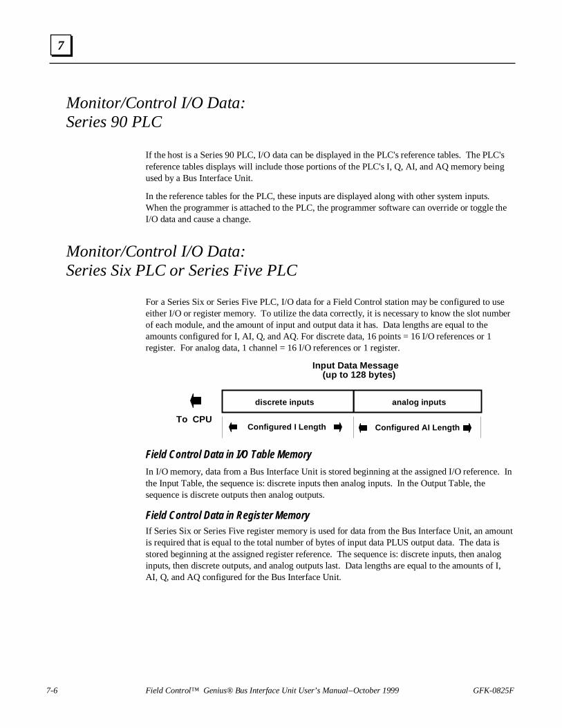
7-6 Field Control™ Genius® Bus Interface Unit User’s Manual – October 1999 GFK-0825F
7
Monitor/Control I/O Data:Series 90 PLC
If the host is a Series 90 PLC, I/O data can be displayed in the PLC's reference tables. The PLC'sreference tables displays will include those portions of the PLC's I, Q, AI, and AQ memory beingused by a Bus Interface Unit.
In the reference tables for the PLC, these inputs are displayed along with other system inputs.When the programmer is attached to the PLC, the programmer software can override or toggle theI/O data and cause a change.
Monitor/Control I/O Data:Series Six PLC or Series Five PLC
For a Series Six or Series Five PLC, I/O data for a Field Control station may be configured to useeither I/O or register memory. To utilize the data correctly, it is necessary to know the slot numberof each module, and the amount of input and output data it has. Data lengths are equal to theamounts configured for I, AI, Q, and AQ. For discrete data, 16 points = 16 I/O references or 1register. For analog data, 1 channel = 16 I/O references or 1 register.
Input Data Message (up to 128 bytes)
discrete inputs analog inputs
Configured I Length Configured AI LengthTo CPU
Field Control Data in I/O Table Memory
In I/O memory, data from a Bus Interface Unit is stored beginning at the assigned I/O reference. Inthe Input Table, the sequence is: discrete inputs then analog inputs. In the Output Table, thesequence is discrete outputs then analog outputs.
Field Control Data in Register MemoryIf Series Six or Series Five register memory is used for data from the Bus Interface Unit, an amountis required that is equal to the total number of bytes of input data PLUS output data. The data isstored beginning at the assigned register reference. The sequence is: discrete inputs, then analoginputs, then discrete outputs, and analog outputs last. Data lengths are equal to the amounts of I,AI, Q, and AQ configured for the Bus Interface Unit.

GFK-0825F Chapter 7 Monitoring and Controlling Field Control Data 7-7
7
Monitor/Control I/O Data:Computer
To utilize the Bus Interface Unit's I/O data correctly, a computer must know the sequence ofmodules in the station, and the amount of input and output data each has.
For the PCIM, QBIM, and other GENI-based interfaces, the input and output data will occupy theDevice Input and Output Tables at the segments associated with the serial bus address of the BusInterface Unit.
I/O Tables
Input Table
Output Table
32 segments, 128 bytes each
32 segments, 128 bytes each
The Bus Interface Unit automatically sends all discrete inputs followed by all analog inputs fromthe station, each bus scan. The PCIM or QBIM places this data into its Input Segment. Theapplication program must read the Input Segment to obtain the input data from the PCIM or QBIM.
Input Table Segment for a Bus Interface Unit
Discrete Inputs Bits(number of bytes = configured
I length / 8)
Analog Input Words(number of bytes = configured
AI length X 2)
The Output Segment is used similarly. The application program must send to the PCIM or QBIM'sOutput Segment all the discrete outputs followed by all the analog outputs for the station. ThePCIM or QBIM will automatically direct the outputs to the Bus Interface Unit each bus scan.

GFK-0825F 8-1
Datagrams
This chapter lists datagrams that can be sent to a Bus Interface Unit, and shows the datagrams forField Control modules that are different from the formats used by other modules.
It also shows the format of configuration data for the Bus Interface Unit and the modules in thestation.
Datagram Types
Read Map
Read Map Reply
Write Map
Report Fault Datagram Format
Configuration Data
Set Bus Interface Unit Operating Mode
Set Micro Field Processor Operating Mode
16 Point Grouped Analog Module Recalibration Datagram
For Additional Information, Also See:
The bus controller User's Manual for the PLC or computer, which explains the specificprogramming used to send datagrams.
The Genius I/O System and Communications Manual, which describes Genius datagrams anddata formats.
8Chapter

8-2 Field Control™ Genius® Bus Interface Unit User’s Manual – October 1999 GFK-0825F
8
Datagram Types
The table below shows the primary datagrams that may be acted upon by the Bus Interface Unit.The table lists the types of device that can send each datagram, and the resulting action taken by theBus Interface Unit.
Datagram Type SubfunctionCode
SentFrom
Bus Interface Unit Action
Read Identification 00 BC, HHM send Read ID Reply
Read Configuration 02 BC, HHM send Read Configuration Reply
Write Configuration 04 BC, HHM process (possibly sendconfiguration changes)
Assign Monitor 05 BC process
Begin Packet Sequence 06 BC, HHM start sequence
End Packet Sequence 07 BC, HHM end/check sequence
Pulse Test 10 HHM send Pulse Test Complete
Clear All Faults 13 BC, HHM process
Set Status Table Address 17 BC, HHM process
Force BSM 1A BC, HHM process (send config. change)
Unforce BSM 1B BC, HHM process (send config. changewhen last point is unforced)
Switch BSM 1C BC process
Set MFP Operating Mode 21 BC
Recalibrate Analog Module 21 BC
Read Map 2A BC, HHM send Read Map Reply
Write Map 2C BC, HHM process-autoconfigure
Set Operating Mode 39 BC process
Read I/O Forces 40 BC send Read I/O Forces Reply
Read Slot Diagnostics 42 BC send Read Slot DiagnosticsReply
A PLC or computer can send a datagram to the Bus Interface Unit in the same manner as sending adatagram to an I/O block or Bus Controller.

GFK-0825F Chapter 8 Datagrams 8-3
8
Read Map
Subfunction Code: 2A hex
This datagram is used to read the reference addresses and lengths that have been configured for theBIU’s network I/O map.
Data Field Format: none
Read Map Reply
Subfunction Code: 2B hex
A Bus Interface Unit sends this reply datagram after receiving a Read Map datagram. It containsthe previously-configured BIU network map addresses. The BIU’s network map defines the BIUmemory locations of the data that is exchanged on the bus. It provides no information about theI/O assignments of individual I/O modules in the station. However, the checksums indicate that theoverall configuration remains unchanged.
Byte No. Byte Description
0 Not used
1 Starting reference for discrete input ( I ) data (LSB)
2 Starting reference for discrete input ( I ) data (MSB)
3 Length of discrete input ( I ) data (in bytes)
4, 5 Starting reference of analog input ( AI ) data
6 Length of analog input ( AI ) data (in bytes)
7, 8 Starting reference of discrete output ( Q ) data
9 Length of discrete output ( Q ) data (in bytes)
10,11 Starting reference of analog output ( AQ ) data
12 Length of analog output ( AQ ) data (in bytes)
13 8-bit Additive Checksum Unused
14, 15 16-bit LRC Critical Checksum (lsb in 14, msb in 15) READ ONLY
16 Field Control 8-bit Additive Checksum. Unused
17, 18 Field Control 16-bit CRC Non-Critical Checksum (lsb in 17, msb in 18) READONLY
Starting references in I, AI, Q, and AQ memory are returned. For each memory type, a data lengthis also supplied. If a length is zero, the associated starting reference can be ignored; it is notmeaningful.

8-4 Field Control™ Genius® Bus Interface Unit User’s Manual – October 1999 GFK-0825F
8
Write Map
Subfunction Code: 2C hex
This datagram allows a CPU to change a previously-configured or unconfigured BIU network mapaddresses, if configuration is not currently protected. The BIU’s network map defines the BIU memorylocations of the data that is exchanged on the bus. Starting references in I, AI, Q, and AQ memory aresent. If any length is zero, the associated starting reference is ignored; it is not meaningful.
Byte No. Byte Description
0 Not used
1 Starting reference for discrete input ( I ) data (LSB)
2 Starting reference for discrete input ( I ) data (MSB)
3 Length of discrete input ( I ) data (in bytes)
4, 5 Starting reference of analog input ( AI ) data
6 Length of analog input ( AI ) data (in bytes)
7, 8 Starting reference of discrete output ( Q ) data
9 Length of discrete output ( Q ) data (in bytes)
10,11 Starting reference of analog output ( AQ ) data
12 Length of analog output ( AQ ) data (in bytes)
13-15 Not used, but these bytes must be present for correct length message.
How a Write Map Datagram Affects I/O Modules in the StationReceiving a Write Map datagram with different starting addresses and/or lengths changes thememory assigned previously configured for the BIU's network map, as explained above. Becauseonly data included within the map is exchanged on the bus, the BIU responds to such changes in itsnetwork map by automatically reassigning the I/O addresses of the modules in the station. Thisassures that the I/O data will continue to be exchanged on the bus. It is important that the lengthssupplied in the Write Map datagram accommodate all of the data that should be exchanged. Thedata of any modules configured outside the BIU's network map will be scanned by the BIU, but notexchanged on the bus.
For example, suppose an I/O station has three 16-point discrete input modules, originallyconfigured to use addresses I0001 through I0048. All of this input data is included in the BIU'snetwork map and is sent on the bus.
Original Configuration: Starting reference: I00001, Length of I data: 6 bytes
I00001 I00009 I00017 I00025 I00033 I00041 I00048
slot 1 slot 2 slot 3
Later, a Write Map datagram is sent to the BIU, specifying a beginning address of I0065 and alength of 5 bytes for I data. The BIU would automatically reassign starting addresses to the I/Omodules starting at I00065. However, this would place 8 inputs (I00105 through I00112) outsidethe network map and the BIU would no longer send those inputs to the host.
Write Map Datagram: Starting reference: I00065, Length of I data: 5 bytes
I00065 I00073 I00081 I00089 I00097 I00105 I00112
slot 1 slot 2 slot 3

GFK-0825F Chapter 8 Datagrams 8-5
8
Report Fault Datagram Format
The format of Report Fault datagrams sent by a Bus Interface Unit is shown below. The Series90-70 Bus Controller interprets this information automatically; no datagram programming isrequired.
If the host is a Series Six or Series Five PLC, this information is ignored. If the host is a computer,this information can be retrieved from the unsolicited datagram queue, and interpreted as neededfor the application.
Subfunction Code: 0F hex
Byte # Description
0 Fault Byte 1
1 Fault Byte 2
2 Fault byte 3
3 Fault byte 4
4 Fault byte 5
5 Fault byte 6
6 Fault byte 7
Fault Byte 1
7 6 5 4 3 2 1 0
byte 0
Fault type, always: 0 0 1 1Type of module reporting fault:
Suppress alarm (short fault only)
Always 0
00 = discrete output01 = discrete input10 = analog output11 = analog input
Fault Byte 2
7 6 5 4 3 2 1 0
byte 1
Diagnostic table byte number (0 - 63) NOT USED This value points to an internal table where the Bus Interface Unit stores the English ASCII text used by the Hand-held Monitor to create its fault message displays.

8-6 Field Control™ Genius® Bus Interface Unit User’s Manual – October 1999 GFK-0825F
8
Fault Byte 3
7 6 5 4 3 2 1 0
byte 2
Fault record number (always 0)Number of fault records (always 1)
Fault Bytes 4 and 5
Fault bytes 4 and 5 (bytes 3 and 4 of the datagram) identify the reference offset (within the BusInterface Unit itself) assigned to the faulted module. This is an internal reference, not a Series 90-70 reference.
7 6 5 4 3 2 1 0
byte 3
Diagnostic reference address, LSB
7 6 5 4 3 2 1 0
byte 4
Diagnostic reference address, MSB
Fault Bytes 6 and 7
Fault bytes 6 and 7 (datagram bytes 5 and 6) are interpreted by the Series 90-70 Bus Controllerautomatically. They are not relevant to other types of host.
7 6 5 4 3 2 1 0
byte 5
7 6 5 4 3 2 1 0
byte 6
Number of Series 90-70 fault entries to set (bit 7 = 1)OR: Fault byte mask for S90-70 Bus Controller dualport (bit 7 = 0).
Fault entire I/O module
Entity offset into diagnostic table
Fault entire Bus Interface Unit

GFK-0825F Chapter 8 Datagrams 8-7
8
1
2
3
4
5
6
7
8
0BIU
Configuration Data
For a Bus Interface Unit, the data format of configuration data transferred by Read ConfigurationReply and Write Configuration datagrams is slightly different than the format for other Geniusdevices. Instead of an offset, the data specifies the slot number of a specific device in the FieldControl Station. The length specified must exactly match the length of the configuration data forthe module (Bus Interface Unit or other module in the station); partial configuration data cannot bewritten. For programming instructions, you will need to refer to the Bus Controller User's Manualfor the PLC. For the Series 90-70 PLC, COMREQ 15 must be used with a Read Configurationdatagram.
Configuration files for conventional Field Control modules can be read or written one module permessage. However, the configuration files of intelligent modules may exceed the 128-bytemaximum length of a Genius message. Therefore, any Write Configuration to an intelligent modulemust be contained within a Begin/End Packet Sequence.
Read Configuration Data
Subfunction Code: 02 hex
The Read Configuration Datagram is used to read configuration data. The datagram format isdifferent for conventional Field Control modules or intelligent modules.
Read Configuration Data Format for Field Control Conventional Modules
Byte # Description
0 Slot number
1 Length (will return minimum 6 bytes to maximum 128 bytes, or specificamount requested. It can be more or less than the configured size forthe slot. If more data is requested than is available for a slot, the extradata bytes will contain zeros.)
Read Configuration Datagram Format for Field Control Intelligent Modules
Configuration data for the BIU and other intelligent modules is transmitted in packets. Dependingon the module type, there can be many packets. Each packet can be up to 128 bytes long.
Byte # Description
0 Slot number in bottom nibble, Intelligent Packet in upper nibble.Examples:
01(hex) reads packet 0 of intelligent module in slot 111(hex) reads packet 1 of intelligent module in slot 1.
1 Length in bytes (maximum per packet is 128)
2 (optional). If the slot number is 0 (the location of the BIU), and this byteis not included or if it is set to FF(hex), the BIU configuration isreturned.If this byte is set to 01(hex) through 10(hex), the appropriate groupinformation is returned.

8-8 Field Control™ Genius® Bus Interface Unit User’s Manual – October 1999 GFK-0825F
8
Read Configuration Reply Data
Subfunction Code: 03 hex
This datagram is a reply to the Read Configuration datagram. The following pages show theformats of configuration data for Field Control devices.
Byte # Description
0 Slot (corresponds to slot supplied in Read Configuration message1 Length (depends on module type)
2-N Data format shown on the following pages
Write Configuration Data
Subfunction Code: 04 hex
The Write Configuration datagram is used to send configuration data. Content of the data is thesame as the Read Configuration Reply. Do not send partial configuration data.
Write Configuration Data Format for Field Control Conventional Modules
Byte # Description
0 Slot (Bus Interface Unit is 0)1 Length (must match the length for the specific device whose
configuration will be written.)2-N Data format shown on the following pages
Use the Begin and End Packet sequence messages to ensure that a sequence of Write Configurationmessages is treated as a single entity. Each packet should be in slot order. Multiple packets for aslot must also be in order. Multiple packets must be 128 bytes in length except the last which maybe shorter.
Example:
Begin Packet Sequence (subfunction code 06 hex)
Write Configuration 1 (subfunction code 04 hex)
Write Configuration 2
Write Configuration N
End Packet Sequence (subfunction code 07 hex). This contains the total numberof BYTES in all Write Configuration packets. For FieldControl (only) the End Packet Sequence has 2 bytes. Byte0 is the least significant byte of the data length and byte 1is the most significant.

GFK-0825F Chapter 8 Datagrams 8-9
8
Write Configuration Datagram Format for Field Control Intelligent Modules
When using the Write Configuration datagram to configure Group Moves, the datagram format is:
Byte # Description
0 Slot number in bottom nibble, Intelligent Packet in upper nibble.Examples:
01(hex) writes packet 0 to intelligent module in slot 111(hex) writes packet 1 to intelligent module in slot 1.
1 Length sent, in bytes (maximum per packet is 128)
2 (optional). If the slot number is 0 (the location of the BIU), and this byteis not included or if it is set to FF(hex), the BIU configuration is written.If this byte is set to 01(hex) through 10(hex), the appropriate groupinformation is written.

8-10 Field Control™ Genius® Bus Interface Unit User’s Manual – October 1999 GFK-0825F
8
Bus Interface Unit Configuration Data Format
For the Bus Interface Unit, the slot number is 0. The length varies.
7 6 5 4 3 2 1 0
BSM Switch Time (0 = 2.5 sec, 1 = 10 sec
Byte 14
7 6 5 4 3 2 1 0
unlabelled bits not used
7 6 5 4 3 2 1 0Byte 15 reserved
7 6 5 4 3 2 1 0Byte 16 LSB
MSBByte 17Series Six/Series Five Reference Address(Read Only)
7 6 5 4 3 2 1 0Byte 18
Configuration Length (always 0)(# bytes in Write Configuration Sequence)
7 6 5 4 3 2 1 0Byte 19
Diagnostic Length (# bytes) read only(always 5)
7 6 5 4 3 2 1 0Bytes20 to 26
reserved
7 6 5 4 3 2 1 0
BSM State (read only)
BSM Present (1 = yes, 0 = no)
BSM Controller (1 = yes, 0 = no)BSM Forced (1 = yes, 0 = no)
Bytes 0 to 11 must be: FF hex, 0,0,0,0,0,0,0,0,0,0,0
Byte 12
7 6 5 4 3 2 1 0Byte 13
Serial Bus Address (read only)Baud Rate Code (read only)
CPU Redundancy ( 00 = no redundancy 01 = Hot standby 10 = Duplex 11 = reserved )
Duplex DefaultConfiguration Protection (read only)
0 = 153.6Kb ext 1 = 153.6 Kb std 2 = 76.8 Kb 3 = 38.4 Kb
Fault Reporting Disabled (0 = yes, 1 = no)
7 6 5 4 3 2 1 0Byte 27Sync Module Present (slot 1=bit 0, slot 8=bit 7).Set a bit to 1 to indicate that the Sync Module(Micro Field Processor) is in this slot. Only 1 bitmay be set.

GFK-0825F Chapter 8 Datagrams 8-11
8
Discrete Input Modules Configuration Data Format
Specify the actual slot number and a length of 13.
The reference address is the location in the BIU's I, Q, AI, or AQ memory that is used by themodule's data. Specify only one address, typically in the discrete input (I) table. Set the otheraddress selection bytes to all zeros.
unlabelled bits not used
Bytes 0 to 3 must be: 45 hex, 0,0,0
7 6 5 4 3 2 1 0Byte 12
Input Default or Hold Last State(0 = default, 1 = hold last state)
Fault Reporting (0 = enabled, 1 = disabled)
7 6 5 4 3 2 1 0
7 6 5 4 3 2 1 0Byte 4 LSB
MSBByte 5 I Reference Address or all zeros
7 6 5 4 3 2 1 0
7 6 5 4 3 2 1 0Byte 6 LSB
MSBByte 7
7 6 5 4 3 2 1 0
7 6 5 4 3 2 1 0Byte 8 LSB
MSBByte 9
7 6 5 4 3 2 1 0
7 6 5 4 3 2 1 0Byte 10 LSB
MSBByte 11
Q Reference Address or all zeros
AI Reference Address or all zeros
AQ Reference Address or all zeros

8-12 Field Control™ Genius® Bus Interface Unit User’s Manual – October 1999 GFK-0825F
8
Discrete Output Modules Configuration Data Format
Specify the actual slot number and a length of 30.
The reference address is the location in the BIU's I, Q, AI, or AQ memory that is used by themodule's data. Specify only one address, typically in the discrete output (Q) table. Set the otheraddress selection bytes to all zeros.
unlabelled bits must be 0
Bytes 0 to 3 must be: 51 hex, 0,0,0 for all modules except IC670MDL730
Bytes 0 to 3 must be 20 hex, 0, 0, 0 for Electronic Short Circuit Protection Output Module,IC670MDL730
7 6 5 4 3 2 1 0Byte12
Output Default or Hold Last State(0 = default, 1 = hold last state)Fault Reporting (0 = enabled, 1 = disabled)
Bytes 14 to 29: Circuit Configuration. For each circuit, content is:
7 6 5 4 3 2 1 0Byte 13 reserved (must be 0)
unlabelled bits must be 07 6 5 4 3 2 1 0
Output Default State(0 = off, 1 = on)
7 6 5 4 3 2 1 0
7 6 5 4 3 2 1 0Byte 4 LSB
MSBByte 5 I Reference Address or all zeros
7 6 5 4 3 2 1 0
7 6 5 4 3 2 1 0Byte 6 LSB
MSBByte 7
7 6 5 4 3 2 1 0
7 6 5 4 3 2 1 0Byte 8 LSB
MSBByte 9
7 6 5 4 3 2 1 0
7 6 5 4 3 2 1 0Byte 10 LSB
MSBByte 11
Q Reference Address or all zeros
AI Reference Address or all zeros
AQ Reference Address or all zeros
(Byte #) Byte Description (Byte #) Byte Description14
15
16
17
18
19
20
21
Circuit 1 Configuration
Circuit 2 Configuration
Circuit 3 Configuration
Circuit 4 Configuration
Circuit 5 Configuration
Circuit 6 Configuration
Circuit 7 Configuration
Circuit 8 Configuration
22
23
24
25
26
27
29
29
Circuit 9 Configuration
Circuit 10 Configuration
Circuit 11 Configuration
Circuit 12 Configuration
Circuit 13 Configuration
Circuit 14 Configuration
Circuit 15 Configuration
Circuit 16 Configuration

GFK-0825F Chapter 8 Datagrams 8-13
8
Discrete Combination Input/Output Modules Configuration Data Format
Specify the actual slot number and a length of 20.
Entering the Reference Addresses
The reference addresses are the locations in the BIU's I, Q, AI, or AQ memory used by the module'sdata. In this module configuration only, the input reference is the first non-zero entry WITHOUT thecorresponding bit set in byte 12 (see below) The output reference is the first non-zero entry WITHthe corresponding bit set. In byte 12, bits 4, 5, 6, and 7 define the input reference. For example, if bit6 of byte 12 is set to 1 and a reference is specified in bytes 8 and 9, inputs for the module will bemapped to the AI table. Note that the entries must correspond properly, or the BIU will reject themodule configuration. In a normal configuration for a combination discrete module, inputs go to the Itable and outputs go to the Q table. In that case, you enter the input reference in bytes 4/5 and theoutput reference in bytes 6/7, and set bit 4 of byte 12 to 1. All other reference address bytes and otherinput reference bits (in byte 12) must be set to zero.
unlabelled bit must be 0
Bytes 0 to 3 must be: 21 hex, 0,0,0
7 6 5 4 3 2 1 0Byte 12
Input Default or Hold Last State(0 = default, 1 = hold last state)
Fault Reporting (0 = enabled, 1 = disabled)Output Default or Hold Last StateInput Reference is I tableInput Reference is Q TableInput Reference is AI TableInput Reference is AQ Table
Bytes 14 to 19: Output Circuit Configuration. For each output, content is:
7 6 5 4 3 2 1 0Byte 13 reserved (must be 0)
unlabelled bits must be 07 6 5 4 3 2 1 0
Output Default State(0 = off, 1 = on)
7 6 5 4 3 2 1 0
7 6 5 4 3 2 1 0Byte 4 LSB
MSBByte 5 I Reference Address or all zeros
7 6 5 4 3 2 1 0
7 6 5 4 3 2 1 0Byte 6 LSB
MSBByte 7
7 6 5 4 3 2 1 0
7 6 5 4 3 2 1 0Byte 8 LSB
MSBByte 9
7 6 5 4 3 2 1 0
7 6 5 4 3 2 1 0Byte 10 LSB
MSBByte 11
Q Reference Address or all zeros
AI Reference Address or all zeros
AQ Reference Address or all zeros
(Byte #) Byte Description
14
15
16
17
18
19
Output 1 Configuration
Output 2 Configuration
Output 3 Configuration
Output 4 Configuration
Output 5 Configuration
Output 6 Configuration

8-14 Field Control™ Genius® Bus Interface Unit User’s Manual – October 1999 GFK-0825F
8
Conventional Analog Input Modules Configuration Data Format
Specify the actual slot number and a length of 126.
The reference address is the location in the BIU's I, Q, AI, or AQ memory that is used by themodule's data. Specify only one address, typically in the analog input (AI) table. Set the otheraddress selection bytes to all zeros.
unlabelled bits must be 0
For current module, bytes 0 to 3 must be: 32 hex, 0,0,0For voltage module, bytes 0 to 3 must be: 34 hex, 0,0,0
7 6 5 4 3 2 1 0Byte 12
Input Default or Hold Last Value(0 = default, 1 = hold last value)
7 6 5 4 3 2 1 0Byte 13 reserved
7 6 5 4 3 2 1 0
Fault Reporting (0 = enabled, 1 = disabled)Channel Active (0 = active, 1 = inactive)
unlabelled bits must be 0
Bytes 14, 28, 42, 56, 70, 84, 98, 112 (see below)
Range: 00 = 0mA to 20mA 01 = 4mA to 20mA 10 = 0V to 10V 11 = -10V to +10V
7 6 5 4 3 2 1 0
7 6 5 4 3 2 1 0Byte 4 LSB
MSBByte 5 I Reference Address or all zeros
7 6 5 4 3 2 1 0
7 6 5 4 3 2 1 0Byte 6 LSB
MSBByte 7
7 6 5 4 3 2 1 0
7 6 5 4 3 2 1 0Byte 8 LSB
MSBByte 9
7 6 5 4 3 2 1 0
7 6 5 4 3 2 1 0Byte 10 LSB
MSBByte 11
Q Reference Address or all zeros
AI Reference Address or all zeros
AQ Reference Address or all zeros

GFK-0825F Chapter 8 Datagrams 8-15
8
Bytes 14 - 125: Channel Configuration
(Byte #) Byte Description (Byte #) Byte Description14 Input 1: circuit configuration (see above) 70 Input 5: circuit configuration (see above)15 reserved 71 reserved
16, 17 low scaling point, eng. units (lsb in byte 16) 72, 73 low scaling point, eng. units (lsb in byte 72)18, 19 high scaling point, eng. units
(lsb in byte 18)74, 75 high scaling point, eng. units
(lsb in byte 74)20, 21 low scaling point, digital counts
(lsb in byte 20)76, 77 low scaling point, digital counts
(lsb in byte 76)22, 23 high scaling point, digital counts
(lsb in byte 22)78, 79 high scaling point, digital counts
(lsb in byte 78)24, 25 low alarm limit (lsb in byte 24) 80, 81 low alarm limit (lsb in byte 80)26, 27 high alarm limit (lsb in byte 26) 82, 83 high alarm limit (lsb in byte 82)
28 Input 2: circuit configuration (see above) 84 Input 6: circuit configuration (see above)29 reserved 85 reserved
30, 31 low scaling point, eng. units (lsb in byte 30) 86, 87 low scaling point, eng. units (lsb in byte 86)32, 33 high scaling point, eng. units
(lsb in byte 32)88, 89 high scaling point, eng. units
(lsb in byte 88)34. 35 low scaling point, digital counts
(lsb in byte 34)90, 91 low scaling point, digital counts
(lsb in byte 90)36, 37 high scaling point, digital counts
(lsb in byte 36)92, 93 high scaling point, digital counts
(lsb in byte 92)38, 39 low alarm limit (lsb in byte 38) 94, 95 low alarm limit (lsb in byte 94)40, 41 high alarm limit (lsb in byte 40) 96, 97 high alarm limit (lsb in byte 95)
42 Input 3: circuit configuration (see above) 98 Input 7: circuit configuration (see above)43 reserved 99 reserved
44, 45 low scaling point, eng. units (lsb in byte 44) 100, 101 low scaling point, eng. units(lsb in byte 100)
46, 47 high scaling point, eng. units (lsb in byte 46) 102, 103 high scaling point, eng. units(lsb in byte 102)
48, 49 low scaling point, digital counts(lsb in byte 48)
104, 105 low scaling point, digital counts(lsb in byte 104)
50, 51 high scaling point, digital counts(lsb in byte 50)
106, 107 high scaling point, digital counts(lsb in byte 106)
52, 53 low alarm limit (lsb in byte 52) 108, 109 low alarm limit (lsb in byte 108)54. 55 high alarm limit (lsb in byte 54) 110, 111 high alarm limit (lsb in byte 110)
56 Input 4: circuit configuration (see above) 112 Input 8: circuit configuration (see above)57 reserved 113 reserved
58, 59 low scaling point, eng. units (lsb in byte 58) 114, 115 low scaling point, eng. units(lsb in byte 114)
60, 61 high scaling point, eng. units(lsb in byte 60)
116, 117 high scaling point, eng. units(lsb in byte 116)
62, 63 low scaling point, digital counts(lsb in byte 62)
118, 119 low scaling point, digital counts(lsb in byte 118)
64, 65 high scaling point, digital counts (lsb in byte 64) 120, 121 high scaling point, digital counts (lsb in byte 120)66, 67 low alarm limit (lsb in byte 66) 122, 123 low alarm limit (lsb in byte 122)68, 69 high alarm limit (lsb in byte 68) 124, 125 high alarm limit (lsb in byte 124)

8-16 Field Control™ Genius® Bus Interface Unit User’s Manual – October 1999 GFK-0825F
8
Conventional Analog Output Modules Configuration Data Format
Specify the actual slot number and a length of 62.
The reference address is the location in the BIU's I, Q, AI, or AQ memory that is used by themodule's data. Specify only one address, typically in the analog output (AQ) table. Set the otheraddress selection bytes to all zeros.
unlabelled bits must be 0
Bytes 0 to 3 must be: 33 hex, 0,0,0
7 6 5 4 3 2 1 0Byte 12
Output Default or Hold Last Value(0 = default, 1 = hold last value)
7 6 5 4 3 2 1 0Byte 13 reserved (must be 0)
7 6 5 4 3 2 1 0
Fault Reporting (0 = enabled, 1 = disabled)Channel Active (0 = active, 1 = inactive)
unlabelled bits must be 0
Bytes 14, 26, 38, 50 (see below)
Range: 00 = 0mA to 20mA 01 = 4mA to 20mA 10 = 0V to 10V 11 = -10V to +10V
7 6 5 4 3 2 1 0
7 6 5 4 3 2 1 0Byte 4 LSB
MSBByte 5 I Reference Address or all zeros
7 6 5 4 3 2 1 0
7 6 5 4 3 2 1 0Byte 6 LSB
MSBByte 7
7 6 5 4 3 2 1 0
7 6 5 4 3 2 1 0Byte 8 LSB
MSBByte 9
7 6 5 4 3 2 1 0
7 6 5 4 3 2 1 0Byte 10 LSB
MSBByte 11
Q Reference Address or all zeros
AI Reference Address or all zeros
AQ Reference Address or all zeros

GFK-0825F Chapter 8 Datagrams 8-17
8
Bytes 14 - 61: Channel Configuration
(Byte #) Byte Description (Byte #) Byte Description
14 Input 1: circuit configuration (see above) 38 Input 3: circuit configuration (see above)
15 reserved 39 reserved
16, 17 low scaling point, eng. units(lsb in byte 16)
40, 41 low scaling point, eng. units (lsb in byte 40)
18, 19 high scaling point, eng. units(lsb in byte 18)
42, 43 high scaling point, eng. units(lsb in byte 42)
20, 21 low scaling point, digital counts(lsb in byte 20)
44, 45 low scaling point, digital counts(lsb in byte 44)
22, 23 high scaling point, digital counts(lsb in byte 22)
46, 47 high scaling point, digital counts(lsb in byte 46)
24, 25 output default value (lsb in byte 24) 48, 49 output default value (lsb in byte 48)
26 Input 2: circuit configuration (see above) 50 Input 4: circuit configuration (see above)
27 reserved 51 reserved
28, 29 low scaling point, eng. units(lsb in byte 28)
52, 53 low scaling point, eng. units (lsb in byte 52)
30, 31 high scaling point, eng. units(lsb in byte 30)
54, 55 high scaling point, eng. units(lsb in byte 54)
32, 33 low scaling point, digital counts(lsb in byte 32)
56, 57 low scaling point, digital counts(lsb in byte 56)
34, 35 high scaling point, digital counts(lsb in byte 34)
58, 59 high scaling point, digital counts(lsb in byte 58)
36, 37 output default value (lsb in byte 36) 60, 61 output default value (lsb in byte 60)

8-18 Field Control™ Genius® Bus Interface Unit User’s Manual – October 1999 GFK-0825F
8
Intelligent Modules Configuration Data Format
Configuration files of intelligent modules may exceed the 128-byte maximum length of a Geniusmessage. Therefore, any Write Configuration to an intelligent module must be contained within aBegin/End Packet Sequence. The BIU rejects any Write Configuration message for an intelligentmodule that does not follow a Begin Packet message.
Write Configuration for an intelligent module may be packetized by using the upper nibble of theslot byte to indicate a packet number. Data for packets greater than zero is assumed to have anoffset with a slot configuration of (packet_number*128). Therefore, all packets except the last musthave 128 bytes.
Note that all reserved or unused bits must be 0.
Configuration Data for Intelligent Modules, Bytes 0 to 13
The first 13 bytes of configuration data for intelligent modules have the content shown below. Eachintelligent module has additional configuration data listed on the following pages.
Byte Meaning Intelligent Analog Modules (IC670…)
ALG240 ALG281 ALG282 ALG310 ALG330 ALG620 ALG630
Micro FieldProcessor
(IC670MFP100)
0 intelligent module board ID 1Fh
1 reserved must be 0 0
2 unique module identifier 1 8 7 6 5 2 3 4
3 reserved must be 0 0
4 reference types word(bit 0 = 1 means inputs available,bit 1 = 1 means outputs available,both = 1 means inputs and outputsavailable)
3(bits 0and 1
both setto 1)
3 3 3 3 3 3 3
5 reserved must be 0 0
6, 7 length of module’s configuration filein bytes
248 136 248 106 106 84 174 30
8, 9 reserved must be 0 0
10, 11 reserved must be 0 0
12 input/output hold last state/default to 0. Bits are shown below. For each, 0=default, 1-hold last state.
7 6 5 4 3 2 1 0
BSM State (read only)
BSM Present (1 = yes, 0 = no)
BSM Controller (1 = yes, 0 = no)BSM Forced (1 = yes, 0 = no)
CPU Redundancy ( 00 = no redundancy 01 = Hot standby 10 = Duplex 11 = reserved )
Duplex DefaultConfiguration Protection (read only)
13 reserved must be 0 0
14-n additional module data

GFK-0825F Chapter 8 Datagrams 8-19
8
Additional Configuration Data for a 16 Point Grouped Analog Input Module (ALG240)
The content of configuration data bytes 14 to 261 for a 16 Point Grouped Analog Input module(IC670ALG240) is listed below.
See the previous page for the content of bytes 0 to 13.
Byte Description Byte Description
14 Number of input reference parameters (2) 40, 41 Ch1 Low Span (0 to 25000)
15 Number of output reference parameters (1) 42, 43 Ch1 High Span (0 to 25000)
16, 17 Byte length of analog input data (default is 32) 44, 45 Ch 1 Low Eng. Units (-32768 to+32767)
18, 19 Memory type for the module's analog inputdata, usually type AI. Enter one of thefollowing numbers:
16 = I table18 = Q table10 = AI table12 = AQ table
46, 47 Ch 1 High Eng. Units (-32768 to+32767)
20, 21 Relative offset from start of table 48, 49 Ch1 Low Alarm
22, 23 Byte length of discrete diagnostic input data(default is 11)
50, 51 Ch1 High Alarm
24, 25 Memory type for the module's diagnostic inputbits, usually type I. Enter one of the numberslisted above.
52-65 Ch 2 parameters
26, 27 Relative offset from start of table 66-79 Ch 3 parameters
28, 29 Byte length of module's control output bits 80-93 Ch 4 parameters
30, 31 Memory type for the module's control outputbits, usually type Q. Enter one of the numberslisted above.
94-107 Ch 5 parameters
32, 33 Relative offset from start of table 108-121 Ch 6 parameters
34 (bit 4) Line Frequency (0 = 50HZ, 1 = 60HZ) 122-135 Ch 7 parameters
34 (bits 0,1) Filtering Method (0 = None, 1 = 8 average, 2 =16 average)
136-149 Ch 8 parameters
35 reserved 150-163 Ch 9 parameters
36, 37 Active Channel Bit Map 1 bit per channel 164-177 Ch 10 parameters
178-191 Ch 11 parameters
192-205 Ch 12 parameters
206-219 Ch 13 parameters
220-233 Ch 14 parameters
234-247 Ch 15 parameters
38, 39 Ch1 Range:0 no preselected range1 span 4000 to 20000, units 4,000 to 20,0002 span 4000 to 20000, units 0 to 320003 span 0 to 20000, units 0 to 320004 span 0 to 24000, units 0 to 32000Read-only when sending a configuration file.The module sets the range based on thescaling parameters. When the configuration isread back, it indicates the correct range.
248-261 Ch 16 parameters

8-20 Field Control™ Genius® Bus Interface Unit User’s Manual – October 1999 GFK-0825F
8
Additional Configuration Data for an 8 Point Grouped Analog Voltage Input Module(ALG281)
The content of configuration data bytes 14 to 149 for an 8 Point Grouped Analog Voltage Inputmodule (IC670ALG281) is listed below.
See page 8-18 for the content of bytes 0 to 13. PLEASE CHECK; I THINK THE OCMTWRITEUP FOR 22,23, 28,29 WAS WRONG; I MADE THEM MATCH OTHER MODULES.
Byte Description Byte Description14 Number of input reference parameters
(2)40, 41 Ch1 Low Span (-10000 to +10000)
15 Number of output reference parameters(1)
42, 43 Ch1 High Span (-10000 to +10000)
16, 17 Byte length of analog input data (defaultis 16)
44, 45 Ch 1 Low Eng. Units (-32768 to +32767)
18, 19 Memory type for the module's analoginput data, usually type AI. Enter one ofthe following numbers:
16 = I table18 = Q table10 = AI table12 = AQ table
46, 47 Ch 1 High Eng. Units (-32768 to +32767)
20, 21 Relative offset from start of table 48, 49 Ch1 Low Alarm22, 23 Byte length of discrete diagnostic input
data (default is 5)50, 51 Ch1 High Alarm
24, 25 Memory type for the module's diagnosticinput bits, usually type I. Enter one of thenumbers listed above.
52-65 Ch 2 parameters
26, 27 Relative offset from start of table 66-79 Ch 3 parameters28, 29 Byte length of module's control output
bits (default is 1)80-93 Ch 4 parameters
30, 31 Memory type for the module's controloutput bits, usually type Q. Enter one ofthe numbers listed above.
94-107 Ch 5 parameters
32, 33 Relative offset from start of table 108-121 Ch 6 parameters34 (bit 4) Line Frequency (0 = 50Hz, 1 = 60Hz) 122-135 Ch 7 parameters34 (bits
0,1)Filtering Method (0 = None, 1 = 10mS,2 = 20mS)
136-149 Ch 8 parameters
35 reserved36, 37 Active Channel Bit Map 1 bit per channel38, 39 Ch1 Range:
1 span -10000mV to +10000mV2 span 0mV to +10000mV

GFK-0825F Chapter 8 Datagrams 8-21
8
Additional Configuration Data for a 16 Point Grouped Analog Voltage Input Module(ALG282)
The content of configuration data bytes 14 to 261 for a 16 Point Grouped Analog Voltage Inputmodule (IC670ALG282) is listed below.
See page 8-18 for the content of bytes 0 to 13. PLEASE CHECK; I THINK THE OCMTWRITEUP FOR 22,23, 28,29 WAS WRONG; I MADE THEM MATCH OTHER MODULES.
Byte Description Byte Description14 Number of input reference parameters
(2)40, 41 Ch1 Low Span (-10000 to +10000)
15 Number of output reference parameters(1)
42, 43 Ch1 High Span (-10000 to +10000)
16, 17 Byte length of analog input data (defaultis 32)
44, 45 Ch 1 Low Eng. Units (-32768 to+32767)
18, 19 Memory type for the module's analoginput data, usually type AI. Enter one ofthe following numbers:
16 = I table18 = Q table10 = AI table12 = AQ table
46, 47 Ch 1 High Eng. Units (-32768 to+32767)
20, 21 Relative offset from start of table 48, 49 Ch1 Low Alarm22, 23 Byte length of discrete diagnostic input
data (default is 9)50, 51 Ch1 High Alarm
24, 25 Memory type for the module'sdiagnostic input bits, usually type I.Enter one of the numbers listed above.
52-65 Ch 2 parameters
26, 27 Relative offset from start of table 66-79 Ch 3 parameters28, 29 Byte length of module's control output
bits (default is 2)80-93 Ch 4 parameters
30, 31 Memory type for the module's controloutput bits, usually type Q. Enter one ofthe numbers listed above.
94-107 Ch 5 parameters
32, 33 Relative offset from start of table 108-121 Ch 6 parameters34 (bit 4) Line Frequency (0 = 50Hz, 1 = 60Hz) 122-135 Ch 7 parameters
34 (bits 0,1) Filtering Method (0 = None, 1 = 10mS, 2= 20mS)
136-149 Ch 8 parameters
35 reserved 150-163 Ch 9 parameters36, 37 Active Channel Bit Map 1 bit per
channel164-177 Ch 10 parameters
178-191 Ch 11 parameters192-205 Ch 12 parameters206-219 Ch 13 parameters220-233 Ch 14 parameters234-247 Ch 15 parameters
38, 39 Ch1 Range:1 span -10000mV to +10000mV2 span 0mV to +10000mV
248-261 Ch 16 parameters

8-22 Field Control™ Genius® Bus Interface Unit User’s Manual – October 1999 GFK-0825F
8
Additional Configuration Data for an RTD Input Module
The content of configuration data bytes 14 to 97 for an RTD Input module (IC670ALG620) islisted below.
Byte Description Byte Description
14 Number of input reference parameters (2)
15 Number of output reference parameters (2)
16, 17 Byte length of analog input data (0 - 8)
18, 19 Memory type for the module's analog input data,usually type AI. Enter one of the following numbers:
18 = Q table10 = AI table12 = AQ table
20, 21 Relative offset from start of table
22, 23 Byte length of discrete diagnostic input data (0 - 4)
24, 25 Memory type for the module's diagnostic input bits,usually type I. Enter one of the numbers listed above.
26, 27 Relative offset from start of table
28, 29 Byte length of control output bits (0 or 1)
30, 31 Memory type for the module's control output bits,usually type Q. Enter one of the numbers listedabove.
32, 33 Relative offset from start of table
46, 47 RTD type for input 1: 0 = 10 Ohm, Pt L&N
1 = 25 Ohm, Pt IPTS-682 = 25.5 Ohm, Pt @ 0 deg. C Lab Std, alpha = .003923 = 100 Ohm. Pt, DIN43760, alpha=.003854 = 100 Ohm Pt, Burns-Special, alpha=.0039025 = 100 Ohm Pt, IPTS-68, alpha=.003926 = 98.13 Ohm Pt, SAMA-RC21-4, alpha=.0039237 = 100 Ohm Pt, JISC-1604-'81, alpha=.0039168 = 1K Ohm Pt, alpha=.003759 = 10 Ohm Cu @ 25 deg. C IPTS-6810 = 9.035 Ohm, Cu @25 deg. C, alpha=.0042711 = 50 Ohm, Cu, alpha=.0042712 = 100 Ohm Cu, alpha=.0042713 = 100 Ohm Ni IPTS-6814 = 100 Ohm Ni @ 0 deg C DIN43760, alpha=.0061815 = 120 Ohm Ni @ 0 deg. C, alpha=.0067216 = 604 Ohm Ni/Fe @ 0 deg. F, alpha=.0051817 = 1K Ohm, Ni/Fe @ 70 deg. F, alpha=.0052718 = 500 Ohm span, requires conversion type O19 = 3000 Ohm span, requires conversion type O20 = none
34, 35 Byte length of analog output data (should be set to 0) 48, 49 Wire type for input 1 (0 = 3 wire, 1 = 4 wire)
36, 37 Memory type for the module's analog output bits. Notused.
50, 51 Low Alarm for input 1 (-32767 to +32767)
38, 39 Relative offset from start of table 52, 53 High Alarm for input 1 (-32767 to +32767)
40, 41 Line Frequency (0 = 50Hz, 1 = 60 Hz) 54, 55 Offset for input 1 (0 to 3276.7)
42, 43 Channel Active flag for input 1 (0 = inactive, 1 =active)
56-69 Ch 2 parameters
70-83 Ch 3 parameters44, 45 Conversion type for input 1 ( 0 = 1/10 ohms, 1 =linearized temperature in 1/10 degrees C, 2 =linearized temperature in 1/10 degrees F, 3 = percentof span)
84-97 Ch 4 parameters

GFK-0825F Chapter 8 Datagrams 8-23
8
Additional Configuration Data for a Thermocouple Input Module
The content of configuration data bytes 14 to 187 for a Thermocouple module (IC670ALG630) islisted below.
Byte Description Byte Description
14 Number of input reference parameters (2)
15 Number of output reference parameters (2)
16, 17 Byte length of analog input data
18, 19 Memory type for the module's analog input data,usually type AI. Enter one of the followingnumbers: 16 = I table
18 = Q table10 = AI table12 = AQ table
48, 49 Thermocouple type for input 1 (only used forconversion types 1 & 2 (see bytes 46, 47) 0 = none 8 = N
1 = J 9 = G2 = K 10 = C3 = T 11 = D4= E 12 = Platinel II5 = S 13 = non-standard TC 16 = R 14 = non-standard TC 2
20, 21 Relative offset from start of table
22, 23 Byte length of discrete diagnostic input data
24, 25 Memory type for the module's diagnostic input bits,usually type I. Enter one of the numbers listedabove.
50, 51 Range type for input 1. This is used ONLY If rangetype (see bytes 48, 49) is set to 0. 0 = unused 4 = 156 mV
1 = 19.5 mV 5 = 312.5 mV2 = 39 mV 6 = 625 mV3 = 78 mV
26, 27 Relative offset from start of table
28, 29 Byte length of discrete control output data
30, 31 Memory type for the module's control output bits,usually type Q. Enter one of the numbers listedabove.
52, 53 Remote Junction Compensation for input 1 : 0 = none
1 = use local thermistor2 = use a value supplied in the module's analog output (AQ) data3 = use the configured value ( bytes 58, 59)
32, 33 Relative offset from start of table 54, 55 Low Alarm for input 1 (-32767 to +32767)
34, 35 Byte length of analog output data (for cold junctioncompensation), usually type AQ
56, 57 High Alarm for input 1 (-32767 to +32767)
36, 37 Memory type for the module's analog output data(used for remote junction compensation). Usuallytype AQ. Enter one of the numbers listed above.
38, 39 Relative offset from start of table
58, 59 Remote Junction value for input 1. Used only ifRemote Junction Compensation (bytes 52, 53) is3. The module multiplies this value by 100 thenadds it to the input voltage before performinglinearization. (-327.67 to +327.67).
40, 41 Line Frequency (0 = 50 Hz, 1 = 60 Hz)
42, 43 Open circuit checking suppression for input 1 (0 =perform check, 1 = suppress check)
60, 61 Offset for input 1. Used if conversion type (bytes46, 47) is degrees C or F. This value should be inthe same units. The module multiplies the value by100 before using it. Range is -100.00 to +100.00degrees.
44, 45 Channel active for input 1 ( 0 = inactive, 1 = active) 62 - 79 Ch 2 parameters
80 - 97 Ch 3 parameters
98-115 Ch 4 parameters
116-133 Ch 5 parameters
134-151 Ch 6 parameters
152- 169 Ch 7 parameters
46, 47 Conversion type for input 1: 0 = 1/100 millivolts
1 = linearized temperature in 1/10 degrees C2 = linearized temperature in 1/10 degrees F3 = percent of span (fractional format)
170- 187 Ch 8 parameters

8-24 Field Control™ Genius® Bus Interface Unit User’s Manual – October 1999 GFK-0825F
8
Additional Configuration Data for a Current Source Analog Output Module
The content of configuration data bytes 14 to 119 for a Current Source Analog Output module(IC670ALG330) is listed below.
Byte Description Byte Description
14 Number of input reference parameters (1)
15 Number of output reference parameters (2)
16, 17 Byte length of diagnostic discrete input data(0 - 4)
40, 41 Ch1 Range: 0 no preselected range
1 span 4000 to 20000, units 4,000 to 20,0002 span 4000 to 20000, units 0 to 320003 span 0 to 20000, units 0 to 32000
If the range is not 0, the span and engineeringunits (entered in the following eight bytes) mustmatch the selected range. If they do not, themodule will reject the configuration.If the range is 0, the span and engineering unitsare not used and the next eight bytes are notchecked.
18, 19 Memory type for the module's diagnostic inputbits, usually type I. Enter one of the followingnumbers: 16 = I table
18 = Q table10 = AI table12 = AQ table
42, 43 Ch 1 Low Eng. Units (-32768 to +32767)
20, 21 Relative offset from start of table 44, 45 Ch 1 High Eng. Units (-32768 to +32767)
22, 23 Byte length of the module's analog output data(0 - 16)
46, 47 Ch1 Low Span (0 to 20000, <=high)
24, 25 Memory type for the module's analog outputdata, usually type AQ. Enter one of the numberslisted above.
48, 49 Ch1 High Span (0 to 20000, >=low)
26, 27 Relative offset from start of table 50 - 59 Ch 2 parameters
28, 29 Byte length of module's control output bits (0 -2)
60 - 69 Ch 3 parameters
30, 31 Memory type for the module's control outputbits, usually type Q. Enter one of the numberslisted above.
70 - 79 Ch 4 parameters
32, 33 Relative offset from start of table. 80 - 89 Ch 5 parameters
34, 35 Local Default Output (0 = off, 1 = hold) 90 - 99 Ch 6 parameters
36, 37 BIU command timeout in milliseconds(500 to 65535)
100 - 109 Ch 7 parameters
38, 39 Active Channels. One bit per channel. For eachchannel, 0 = inactive, 1 = active)Default is 0xFF, all active).
110 - 119 Ch 8 parameters

GFK-0825F Chapter 8 Datagrams 8-25
8
Additional Configuration Data for an Analog Voltage Output Module
The content of configuration data bytes 14 to 119 for an Analog Voltage Output module(IC670ALG310) is listed below.
Byte Description Byte Description
14 Number of input reference parameters (1)
15 Number of output reference parameters (2)
16, 17 Byte length of diagnostic discrete input data(0 - 3)
40, 41 Ch1 Range: 0 span -10,000 to +10,000,
units -10,000 to +10,000 1 span 0 to +10,000,
units 0 to +10,000
18, 19 Memory type for the module's diagnostic inputbits, usually type I. Enter one of the followingnumbers: 16 = I table
18 = Q table10 = AI table12 = AQ table
42, 43 Ch 1 Low Eng. Units (-32768 to +32767)
20, 21 Relative offset from start of table 44, 45 Ch 1 High Eng. Units (-32768 to +32767)
22, 23 Byte length of the module's analog output data(0 - 16)
46, 47 Ch1 Low Span (-10,000 to +10,000<=high)
24, 25 Memory type for the module's analog outputdata, usually type AQ. Enter one of the numberslisted above.
48, 49 Ch1 High Span (-10,000 to +10,000 >=low)
26, 27 Relative offset from start of table 50 - 59 Ch 2 parameters
28, 29 Byte length of module's control output bits(0 - 2)
60 - 69 Ch 3 parameters
30, 31 Memory type for the module's control outputbits, usually type Q. Enter one of the numberslisted above.
70 - 79 Ch 4 parameters
32, 33 Relative offset from start of table. 80 - 89 Ch 5 parameters
34, 35 Local Default Output (0 = off, 1 = hold) 90 - 99 Ch 6 parameters
36, 37 BIU command timeout in milliseconds (500 to 65535)
100-109 Ch 7 parameters
38, 39 Active Channels. One bit per channel. For eachchannel, 0 = inactive, 1 = active)Default is 0xFF, all active).
110-119 Ch 8 parameters

8-26 Field Control™ Genius® Bus Interface Unit User’s Manual – October 1999 GFK-0825F
8
Additional Configuration Data for a Micro Field Processor Module
The content of configuration data bytes 14 to 43 for a Micro Field Processor module(IC670MFP100) is listed below.
Byte Description Byte Description
14 Number of input reference parameters (2) 28, 29 Byte length of the number of outputs from the BIU tothe MFP's I table. (0 - 64)
15 Number of output reference parameters (2) 30, 31 BIU table to get data for the MFP's I table. Enter oneof the numbers listed above.
16, 17 Byte length of number of inputs to BIU from theMFP's discrete output (Q) table (0 - 64)
32, 33 Byte offset of from the start of the selected BIU tableto get data for the MFP's I table (0 - 255)
34, 35 Byte length of the number of outputs from the BIU tothe MFP's AI table. (0 - 254)
18, 19 BIU table to place Q data from the MFP. Enterone of the following numbers:
16 = I table18 = Q table10 = AI table12 = AQ table
36, 37 BIU table to get data for the MFP's AI table. Enterone of the numbers listed above.
20, 21 Byte offset from the start of the selected BIUtable to put MFP Q table data. (0 - 255)
38, 39 Byte offset of from the start of the selected BIU tableto get data for the MFP's AI table (0 - 255)
22, 23 Byte length of the number of inputs to the BIUfrom the MFP's AQ table. (0 - 254)
40 Number of checksums. O means do not checkprogram logic match. (0 - 255)
24, 25 BIU table to put AQ table from the MFP. Enterone of the numbers listed above.
41 Byte checksum of the MFP ladder logic.
26, 27 Byte offset from the start of the selected BIUtable to put MFP AQ table data. (0 - 255)
42, 43 Word LRC checksum of MFP ladder logic.

GFK-0825F Chapter 8 Datagrams 8-27
8
Group Data Move Configuration Data Format
7 6 5 4 3 2 1 0
BSM Switch Time (0 = 2.5 sec, 1 = 10 sec
Byte 14
7 6 5 4 3 2 1 0
unlabelled bits not used
7 6 5 4 3 2 1 0Byte 15 reserved
7 6 5 4 3 2 1 0Byte 16 LSB
MSBByte 17Series Six/Series Five Reference Address(Read Only)
7 6 5 4 3 2 1 0Byte 18
Configuration Length (unused)(# bytes in Write Configuration Sequence)
7 6 5 4 3 2 1 0Byte 19
Diagnostic Length (# bytes) read only (unused)
7 6 5 4 3 2 1 0Bytes20 to 26
reserved
7 6 5 4 3 2 1 0
BSM State (read only)BSM Present (1 = yes, 0 = no)BSM Controller (1 = yes, 0 = no)BSM Forced (1 = yes, 0 = no)
Bytes 0 to 11 must be: FF hex, 0,0,0,0,0,0,0,0,0,0,0
Byte 12
7 6 5 4 3 2 1 0Byte 13
Serial Bus Address (read only)Baud Rate Code (read only)
CPU Redundancy ( 00 = no redundancy 01 = Hot standby 10 = Duplex 11 = reserved )
Duplex DefaultConfiguration Protection (read only)
0 = 153.6Kb ext 1 = 153.6 Kb std 2 = 76.8 Kb 3 = 38.4 Kb
Fault Reporting Disabled (0 = yes, 1 = no)
7 6 5 4 3 2 1 0Byte 27
Sync Module Present (slot 1=bit 0, slot 8=bit 7)

8-28 Field Control™ Genius® Bus Interface Unit User’s Manual – October 1999 GFK-0825F
8
Group Move 1
The diagram below shows the sequence of group mode configuration data for Group Move 1,Move 1 and Move 2. The format for subsequent moves is the same.
7 6 5 4 3 2 1 0
7 6 5 4 3 2 1 0Byte 28
Byte 29
7 6 5 4 3 2 1 0
7 6 5 4 3 2 1 0Byte 30
Byte 31
7 6 5 4 3 2 1 0
7 6 5 4 3 2 1 0Byte 32
Byte 93
7 6 5 4 3 2 1 0
7 6 5 4 3 2 1 0Byte 34
Byte 35
Source Slot
Destination Slot
Which Sweeps Data Group Will Be Moved
Hold Last State/Defailt
Source Table Segment Selector
Destination Table Segment Selector
Source Offset in bytes, LSB
Source Offset in bytes, MSB
Byte Length of Data, LSB
Byte Length of Data, MSB
Source Table Segment Selector
Destination Table Segment Selectot
Source Offset in bytes, LSB
Source Offset in bytes, MSB
Byte Length of Data, LSB
Byte Length of Data, MSB
7 6 5 4 3 2 1 0
7 6 5 4 3 2 1 0Byte 36
Byte 37
7 6 5 4 3 2 1 0
7 6 5 4 3 2 1 0Byte 38
Byte 39
7 6 5 4 3 2 1 0
7 6 5 4 3 2 1 0Byte 40
Byte 41
7 6 5 4 3 2 1 0
7 6 5 4 3 2 1 0Byte 42
Byte 43
7 6 5 4 3 2 1 0
7 6 5 4 3 2 1 0Byte 44
Byte 45
7 6 5 4 3 2 1 0
7 6 5 4 3 2 1 0Byte 46
Byte 47
Destination Offset in bytes, LSB
Destination Offset in bytes, LSB
Destination Offset in bytes, MSB
Group Move 1
Submove 1
Submove 2
Destination Offset in bytes, MSB
The high byte of address + 2 of the pointer is not used; it must be zero. The low byte of address + 2specifies the type of memory where the Status Pointer will be located.
For This Memory Type: Enter This Number:
I discrete input table 16
Q discrete output table 18
R register memory 8
AI analog input table 10
AQ analog output table 12

GFK-0825F Chapter 8 Datagrams 8-29
8
Set Bus Interface Unit Operating Mode
Subfunction Code: 39 hex
This datagram can be used to set the operating mode of the Genius Bus Interface Unit.
Byte No. Byte Description
0 Mode
1 Mode
This message has two copies of the mode parameter. These copies must be equal for the commandto be accepted by the Bus Interface Unit.
If you disable the network, the BIU sends no inputs and receives no outputs.
Bytes 0 and 1 (Must Match)
7 6 5 4 3 2 1 0
I/O Scan Enable/Disable (1 = enable, 0 = disable)
Run/Stop Local Programming (FUTURE)Network Enabled/disabled
Unused (must be 0)
(0 = enable, 1=disable)
Set Micro Field Processor Operating Mode
Subfunction Code: 21 hex
This datagram can be used to set the operating mode of a Micro Field Processor in the I/O Station.
Byte Value Description
0 F6 hex Message code
1 18 hex Command code
2 Slot # The slot number of the Micro Field Processor
3 0 Reserved
4 0 Offset of the Least Significant Byte of the data
5 0 Offset of the Most Significant Byte of the data
6 4 Data length.
7 47 hex
8 45 hex
9 46 hex
10 0 Code to set Micro Field Processor mode:0 = Stop/No I/O Mode

8-30 Field Control™ Genius® Bus Interface Unit User’s Manual – October 1999 GFK-0825F
8
Intelligent Analog Module Recalibration Datagram
Subfunction Code: 21 hex
This datagram can be used to recalibrate a 16 Point Analog Grouped module (IC670ALG240), torestore the factory calibration, or to place the module into “warmup” mode for recalibration.
Byte Value Description
0 F6 hex Message code
1 18 hex Command code
2 Slot # The module's slot number
3 0 Reserved
4 0 Offset of the Least Significant Byte of the data
5 0 Offset of the Most Significant Byte of the data
6 length of data Data length as shown in the following tables.
7-133 data See below.
Message Content for Calibrating Low End of Channel
Byte Value Description
7 0 Reserved
8 Channel # Channel to be calibrated (0 - 15)
9 0 Request to calibrate low end
10, 11 Current in microAmps.Recommended range is 3500 to 4500 microAmps.
12, 13 0-65535 Number of readings to average.
14 - 20 0 Reserved
Message Content for Calibrating High End of Channel
Byte Value Description
7 0 Reserved
8 Channel # Channel to be calibrated (0 - 15)
9 1 Request to calibrate high end
10, 11 Current in microAmps.Recommended range is 19500 to 20500microAmps.
12, 13 0-65535 Number of readings to average.
14 - 20 0 Reserved

GFK-0825F Chapter 8 Datagrams 8-31
8
Field RecalibrationThe 16 Point Grouped Analog Input module is calibrated at the factory. It can also be recalibratedfrom the host, to adapt to different conditions. Calibration data consists of two sets of values for eachchannel. One value is provided to the module during calibration. The other value is a correspondingA/D sample value for that current that is determined by the module. One pair of values represents alow value (typically 4mA) and the other represents a high value (typically 20mA).
Recalibration, if needed, is done as described below.
1. Connect a known current to each of the channels.
2. (Optional) Place the module in warmup mode by sending the warmup command from the host.
3. Send the calibration command from the host. The calibration command specifies the channel tocalibrate and the current being supplied to the channel's input. There is a calibrate commandfor a high point and one for a low point.
4. The module samples the channel and calculates the nominal value using the default calibrationdata. The module reads the number of samples specified in the command (1 to 65535) andcalculates the average. It then stores the current value and the sample average and recalculatesthe scaling constants for the channel.
5. The module returns status information about the recalibration to the BIU.
Message Content for Storing New Calibration to Field Area
Byte Value Description
7 0 Reserved
8 0 Reserved
9 3 Code to store to field area
10 - 20 0 Reserved
Message Content for Reverting to Factory Calibration
Byte Value Description
7 0 Reserved
8 0 Reserved
9 4 Code to revert to factory calibration
10 - 20 0 Reserved
Message Content for Putting Module in Warmup Mode
Byte Value Description
7 0 Reserved
8 0 Reserved
9 5 Code to put module in warmup mode
10 - 20 0 Reserved

8-32 Field Control™ Genius® Bus Interface Unit User’s Manual – October 1999 GFK-0825F
8
Read I/O ForcesSubfunction Code: 40 hexThis datagram can be used to set read force information from a Genius Bus Interface Unit. Theinformation read is determined by the value specified in the datagram.
Byte # Description
0 Force Table Requested: 0 = input enable1 = output enable2 = input values3 = output values
• To read which inputs are forced, specify the number 0 in the datagram.• To read which outputs are forced, specify 1 in the datagram.• To read forced input values, specify 2 in the datagram.• To read forced output values, specify 3 in the datagram.
In the BIU, two force enable tables show which points are forced. Two force values tables show theforced values. Each table contains a byte of data for each byte of discrete data followed by a wordof data for each channel of analog data. For example, if a BIU is configured to have 6 bytes ofdiscrete input data and 6 channels of analog input data, the input force enable table and input forcevalue table would look like this:
Force Enabled Table Force Values Table
Byte # Description Byte # Description
0 1st 8 discrete inputs force enable 0 1st 8 discrete inputs force values
1 2nd 8 discrete inputs force enable 1 2nd 8 discrete inputs force values
2 . 2 .
3 . 3 .
4 . 4 .
5 last 8 discrete inputs force enable 5 last 8 discrete inputs force values
6, 7 1st channel analog inputs force enable 6, 7 1st channel analog inputs force values
8, 9 2nd channel analog inputs force enable 8, 9 2nd channel analog inputs force values
10, 11 . 10, 11 .
12, 13 . 12, 13 .
14, 15 . 14, 15 .
16, 17 6th channel analog inputs force enable 16, 17 6th channel analog inputs force value
Note that it is possible to have no discrete inputs or outputs or no analog inputs or outputs.
Read I/O Forces ReplySubfunction Code: 41 hex
This datagram provides the information requested by a Read I/O Forces datagram.
Byte # Description
0 Force Table Requested: 0 = input enable1 = output enable2 = input values3 = output values
1 - 128 Input/Output force enable/value table data
For discrete data, a 1 in a bit position in the force enable table corresponds to an enabled force forthat point. For analog data, the value FFFF (hex) in a word position in the enable table correspondsto an enabled force for an analog channel.

GFK-0825F Chapter 8 Datagrams 8-33
8
Read Slot Diagnostics
Subfunction Code: 42 hex
This datagram can be used to read diagnostics information for a specific slot, point, or channelfrom a BIU. This message does not provide channel or point information for intelligent modules(which includes certain types of I/O modules and Micro Field Processors). Intelligent modules canbe configured to provide the information automatically.
Byte # Description0 Slot number: 1 - 8
Read Slot Diagnostics ReplySubfunction Code: 43 hex
This datagram provides the information requested by a Read Slot Diagnostics datagram.
Byte # Description0 Slot number: 1 - 8
1 Board Status for slot
2 Board identification fault bit (msb)
3 - 18 Slot diagnostics data (no meaning for discrete boards)
Board Status (Byte 1)7 6 5 4 3 2 1 0
ConfiguredMismatched Board IDMissing Mismatched I/OExtra I/O ModuleStatus: No User Power (for some analog modules)Smart Module AvailableUnsupported module type
For conventional I/O modules, 01 in this byte indicates no faults. For intelligent modules, 41 hexindicates no faults.
Board ID (Byte 2)If the designated slot has a discrete output module, the most significant bit of byte 2 indicateswhether the module has a blown fuse or loss of user power fault.
If the designated slot has a conventional analog input module, the most significant bit of byte 2indicates a loss of user power fault.
This byte has no meaning for other types of modules.
Bytes 3 - 18 (Slot Diagnostics Data)
7 6 5 4 3 2 1 0
Input channel low alarmInput channel high alarmChannel underrangeChannel overrangeChannel open wire, for analog input modules in 4-20mA rangereservedLoss of user power for analog output modules only

GFK-0825F A-1
Scaling Analog Channels
This appendix explains how to select scaling values when configuring an analog input or output.See chapter 5 for configuration instructions.
How Scaling Works
Analog modules convert between electrical signals (current or voltage) and digital values. Thesedigital values are 0 to 4095 (for 12-bit converters). Digital values are often referred to as “counts”They represent the data that is transferred between the Bus Interface Unit and an analog module.
To make the input or output data of conventional analog modules more meaningful to theapplication, the Bus Interface Unit performs a conversion process called scaling (note that the BIUperforms scaling only for conventional analog modules; “ntelligent” analog modules perform theirown scaling). Scaling converts the module's digital values to or from the engineering units valuesused by the application.
Typically, the engineering units represent millivolts or microamps. In other cases, they representphysical units such as degrees or centimeters per second. Since engineering units values areintegers from -32767 to +32767, it is often necessary to use fractional units (such as hundredths ofdegrees) to preserve the resolution of a physical input or output.
Each channel of an analog module can be scaled independently. Scaling is configured by enteringcorresponding low and high engineering units values and low and high internal values for twopoints. The internal values represent millivolts or microamps.
The BIU uses the straight line defined by the two pairs of values to convert between engineeringunits and analog convertor counts. The conversion takes into account the module type and therange that is selected.
AAppendix

A-2 Field Control™ Genius® Bus Interface Unit User’s Manual – October 1999 GFK-0825F
A
Scaling Values for 1mV or 1µA Engineering Units: BIU Version 1.3
For many applications, the engineering units are either millivolts or microAmps. These units areeasy to scale. Simply use the table below to find scaling values that are appropriate for thechannel's configured range.
Analog Current Input Module
RangeSelected
To measurethis current
Enter this engineeringunits value
Internal Units(microAmps)
4 to 20mA 4 mA Low 4,000 Low 4,000
20 mA High +20,000 High +20,000
0 to 20 mA 0 mA Low 0 Low 0
20 mA High +20,000 High +20,000
Analog Current Output Module
RangeSelected
To output thiscurrent
Enter this engineeringunits value
Internal Units(microAmps)
4 to 20mA 4 mA Low 4,000 Low 0
20 mA High +20,000 High +20,000
0 to 20 mA* 0 mA Low 0 Low 0
20 mA High +20,000 High +20,000
Analog Current Source Output Module (IC670ALG320) in Voltage Mode
RangeSelected
To output thisvoltage
Enter this engineeringunits value
Internal Units(microAmps)
4 to 20mA 0 volts Low 0 Low 0
+10 volts High +10,000 High +20,000
0 to 20 mA* 0 volts Low 0 Low 0
+12.5 volts High +12,500 High +20,000
* Connect the output load between Volt (V) and Return (RET) for thechannel being used. For 0 to +12.5 voltage, place a jumper between RETand JMP on the terminal block.
Horner Analog Voltage Input Module (HE670ADC810)
RangeSelected
To measurethis voltage
Enter this engineeringunits value
Internal Units(microAmps)
0 to 10 volts 0 volts Low 0 Low 0
+10 volts High +10,000 High +10,000
-10 to +10 volts -10 volts Low -10,000 Low -10,000
+10 volts High +10,000 High +10,000

GFK-0825F Appendix A Scaling Analog Channels A-3
A
Scaling Values for 1mV or 1µA Engineering Units: BIUVersion 2.0 or Later
For many applications, the engineering units are either millivolts or microAmps. These units areeasy to scale. Simply use the table below to find scaling values that are appropriate for thechannel's configured range.
Analog Current Input Module
RangeSelected
To measurethis current
Enter this engineeringunits value
Internal Units(microAmps)
4 to 20mA 4 mA Low +4,000 Low +4,000
20 mA High +20,000 High +20,000
0 to 20 mA 0 mA Low 0 Low 0
20 mA High +20,000 High +20,000
Analog Current Output Module
RangeSelected
To output thiscurrent
Enter this engineeringunits value
Internal Units(microAmps)
4 to 20mA 4 mA Low +4000 Low +4000
20 mA High +20,000 High +20,000
0 to 20 mA* 0 mA Low 0 Low 0
20 mA High +20,000 High +20,000
Analog Current Source Output Module (IC670ALG320) in Voltage Mode
RangeSelected
To output thisvoltage
Enter this engineeringunits value
Internal Units(microAmps)
4 to 20mA 0 volts Low 0 Low +4000
+10 volts High +10,000 High +20,000
0 to 20 mA* 0 volts Low 0 Low 0
+12.5 volts High +12,500 High +20,000* Connect the output load between Volt (V) and Return (RET) for the
channel being used. For 0 to +12.5 voltage, place a jumper between RETand JMP on the terminal block.
Horner Analog Voltage Input Module (HE670ADC810)
RangeSelected
To measurethis voltage
Enter this engineeringunits value
Internal Units(microAmps)
0 to 10 volts 0 volts Low 0 Low 0
+10 volts High +10,000 High +10,000
-10 to +10 volts -10 volts Low -10,000 Low -10,000
+10 volts High +10,000 High +10,000

A-4 Field Control™ Genius® Bus Interface Unit User’s Manual – October 1999 GFK-0825F
A
Measuring Scaling Values
If the circuit will not use millivolt or microAmp units, the most accurate scaling values can befound by taking actual measurements of the process. The process must be set to two distinctlydifferent conditions, so two sets of measurements can be taken.
If the analog module is already installed, you can use it online to the process being measured toobtain actual data values. By default, the Bus Interface Unit performs a 1 to 1 scaling on allchannels. (Using the online method requires the prior configuration of at least the serial busaddress, the I/O map, and the module I/O references).
Finding the Digital Value with the Module Online to the Process
If the module is online to the process, follow the steps below to find the scaling values.
1. Set the process to the first condition to be measured.
2. Using a suitable external device, find the engineering units measurement (for example, PSI, ordegrees).
3. Read the corresponding value with the Hand-held Monitor or the Logicmaster software. Theunits (using the default scaling) are millivolts or microAmps.
• using a Hand-held Monitor in default mode, go to the Monitor screens (see chapter 7 ifyou need further instructions) and read the channel's digital value.
• using the Logicmaster software, go to the appropriate data table and read the channel'sdigital value.
4. Set the process to the second condition to be measured and repeat steps 2 and 3 to find thesecond pair of scaling values.
Finding the Digital Value without the Module Online
If the module is not online to the process, you will need to take two measurements from theprocess, and also measure the voltage or current associated with each. Convert this measurement tomillivolts (for voltage) or microAmps (for current).

GFK-0825F Appendix A Scaling Analog Channels A-5
A
Example of Scaling an Analog Input
A channel is configured in the 0 to 10 volts DC range. It measures a velocity input. Electronicsensors and mechanical linkage external to the block have determined that an input level of +1.5volts DC is equal to -20 feet/second (-6 meters/second), and that +9 volts DC is equal to +180feet/second (+50 meters/second). Plotting these values on a graph shows that a signal of 5 voltsDC corresponds to a speed of 73.3 feet/second.
46746
+10.0+5.0 +9.0
200
100
Velocity
InputVoltage
50
150
-50
-20
-60(+1.5V, -20 ft/sec)
(+9.0V, +180 ft/sec)
For engineering units of feet per second, the following scaling values are used:
Low engineering units = -20 ft/secHigh engineering units = +180 ft/secLow internal units = 1500 millivoltsHigh internal units = 9000 millivolts
An input value of 5.0 volts would be scaled to an engineering value of +00073 (ft/sec).
In this example, scaling to hundredths of feet per second would provide better resolution. Thefollowing scaling values would be used:
Low engineering units = -2000 hundredths ft/secHigh engineering units = +1800 hundredths ft/secLow internal units = 1500 millivoltsHigh internal units = 9000 millivolts
An input value of 5.0 volts would be scaled to an engineering value of +7333 (hundredths ft/sec).

GFK-0825F B-1
Installing Additional Suppression
This appendix describes some precautions that can be taken in an installation to help assure properoperation.
It is possible some installations might exceed the surge immunity capabilities specified in chapter1. This is most likely in outdoor installations or where the power source is from another building orground system. It is prudent to provide local transient protection.
Note
MOVs do a good job of absorbing transients on communications, control, andpower lines, provided the total energy of those transients does not exceed therating of the device.
However, if the energy of the transient exceeds the rating of the device, the MOVmay be either damaged or destroyed. This failure may not be visibly orelectrically evident. MOVs should be regularly inspected for signs of damage toassure continued protection against transients. For some applications, periodicreplacement of critical MOVs is recommended, even if they do not show signs ofdamage.
Suppression at the Power Lines
Protection can be provided by connecting higher-energy MOVs across the power lines (forinstance, between Hot and Neutral) and from line to frame ground (safety ground). This triangularconfiguration requires three MOVs for each long power feed. If the total power feed length is about100 feet or less, one set of MOVs should be enough for any number of devices. The axial-leadedLA series of MOVs from Harris is often used. The 14mm size, model V130LA10 rated at 38joules is usually sufficient. The MOVs used should be able to handle most line transients.Measurement of actual transients may be required in extreme cases to decide what MOVs to use.
BAppendix

B-2 Field Control™ Genius® Bus Interface Unit User’s Manual – October 1999 GFK-0825F
B
Suppression for Devices in an Enclosure
For a group of devices installed in an enclosure, the MOVs can be installed at the point where thepower lines enter the enclosure. Ideally, MOVs should be used at each cabinet in the system formaximum protection. The following illustration shows suppression on both power lines and thecommunications bus for modules in an enclosure.
Enclosure
Powerto
Modules
Short Length of Bus to All Bus Interface Units
46461
Suppression at the Communications Line
For an individual Bus Interface Unit, suppression can be supplied by connecting two small MOVsfrom Serial 1 and Serial 2 to the Bus Interface Unit's Shield Out terminal:
S1
S2
SHLD IN
SHLD OUT
(bus cable not shown)
MOVs
46463
Suitable MOVs include Harris part number V220MA2A, Panasonic ERZ-CO5FK221U, andSiemens 505K140. If necessary, higher energy-rated devices can also be used. It is important to besure that the MOV leads do not cause any shorts between the serial data and shield connectors.
Chapter 2 of the Genius I/O System and Communications Manual (GEK-90486-1) describes thenoise-rejection and filtering capabilities of the Genius bus. It explains bus wiring practices for allapplications. That chapter also gives additional instructions for installing a bus outdoors or betweenbuildings, including recommendations for adding suppression at the point where the bus enters abuilding.
GFK-0825F C-1
The Genius Serial Bus
This appendix describes the selection and operating characteristics of the bus cable that links Geniusdevices. This information supercedes the equivalent text portion of chapter 2 of The Genius I/O Systemand Communications Manual (GFK-90486), “The Communications Bus”.
A Genius serial bus consists of two or more Genius devices, and (usually) the bus cable thatconnects them. A single block or bus controller with a Hand-held Monitor directly attached,properly terminated with a 75 Ohm resistor, is considered the smallest possible Geniuscommunications bus.
Wiring GuidelinesFour types of wiring may be encountered in a typical factory installation:
1. Power wiring - the plant power distribution, and high power loads such as high horsepower motors.These circuits may be rated from tens to thousands of KVA at 220 VAC or higher.
2. Control wiring - usually either low voltage DC or 120 VAC of limited energy rating. Examples arewiring to start/stop switches, contactor coils, and machine limit switches. This is generally theinterface level of the Genius discrete I/O.
3. Analog wiring - transducer outputs and analog control voltages. This is the interface level to GeniusI/O analog blocks.
4. Communications and signal wiring - the communications network that ties everything together,including computer LANs, MAP, and Genius I/O and communications bus.
These four types of wiring should be separated as much as possible to reduce the hazards frominsulation failure, miswiring, and interaction (noise) between signals. A typical PLC system withGenius I/O may require some mixing of the latter three types of wiring, particularly in crampedareas inside motor control centers and on control panels. In general, it is acceptable to mix theGenius bus cable with the I/O wiring from the blocks, as well as associated control level wiring.All noise pickup is cumulative, depending on both the spacing between wires, and the distancespan they run together. I/O wires and Genius bus cable can be placed randomly in a wiring troughfor lengths of up to 50 feet. If wiring is cord-tied (harnessed), do not include the bus cable in theharness, since binding wires tightly together increases the coupling and mechanical stress that candamage the relatively soft insulation of some serial cable types.
Wiring external to equipment and in cable trays, should be separated following NEC practices. Thepickup over long-distance runs with adequate spacing consists of common mode and groundvoltage differences. These are rejected due to the differential transmission mode of the Genius busand the bus isolation transformers built into each Genius I/O block.
CAppendix

C-2 Field Control™ Genius® Bus Interface Unit User’s Manual – October 1999 GFK-0825F
C
Electrical InterfaceThe Genius serial bus uses computer grade twisted pair data cable. The half duplex token sequenceused requires only a single pair since at any time only one station is transmitting and all others arereceiving. All stations must receive in order to track the present token value and take theirappropriate turn on the bus, regardless whether the data is to be used locally. The transmit sequenceis the same as the serial bus address (SBA) set into each location during configuration. Asimplified interface circuit is shown below:
LOCALSUPPLY
CHASSISGROUND
COMP
COMP
R
R
RX+
RX-
TX+
TX-
INTERFACE LOGIC
+ REF
- REF
LOCALCOMMON
ISOLATION
SHIELDIN
SHIELDOUT
SER1
SER2
+5 to 10 V
SER1
SER2
SER2
Wiring Terminals
Signal coupling to the bus is via a high frequency, high isolation pulse transformer. This permitsthe bus and the local logic to be at different voltage levels. The pulse waveforms are bipolar (seenext section below) to reduce DC baseline offsets in the waveform.
The daisy-chained bus is shown on the left in the above illustration. The SER 1 and SER 2 linesare merely tapped at the intermediate locations along the bus. These connections must be consistentsince the signal is polarized. The shield of the cable is broken into segments at each location. Eachshield segment is DC grounded at one end (SHIELD OUT), and terminated with a small capacitorat the other (SHIELD IN). The segmenting breaks up long ground loop paths. The capacitortermination reduces common mode noise from high frequency pickup, while preventing largeground loop currents in the shield at low frequencies.
The alternately switching transistors produce a negative pulse followed by a positive pulse acrossSERIAL 1 relative to SERIAL 2. The bit waveform is a series of these pulses, as will be shownlater. The transformer provides isolation (2500 volts test) between the bus and the local logic,permitting these to be at different voltages. The internal resistors in each line provide current limitand some termination function during transmission.
The balanced (differential) signals on the twisted pair provide high noise immunity due to themagnetic (H field) cancellation effect of the twisting, as well as electric (E field) reduction by theshielding. Most remaining noise pickup is common mode: the transformer provides a high commonmode noise rejection by looking only at the differential signal across the SER 1-2 lines. The twoinput comparators detect the positive polarity input pulses separately from the negative; these aresent to a custom interface logic chip which digitally filters these for timing and sequence, thenreconstructs the NRZ digital data. Voltages between the two thresholds are ignored. This filtering,and the high input threshold if the comparators, are highly effective in rejecting both randomimpulse noise and low level line reflections. Finally a CRC-6 checksum check is performed beforethe data is sent to the local processor (not shown).

GFK-0825F Appendix C The Genius Serial Bus C-3
C
Genius Transceiver Electrical Specification
Property Min Max
Normal peak voltage Vp into 78 ohm terminated cable (1) 3.5 volts 5.5 volts
Normal peak voltage Vp into 150 ohm terminated cable (1) 6.0 volts 9.5 volts
Rated bus impedance (2) 78 ohms 150 ohms
Maximum output voltage (SER 1 and 2 open) (3) Peak RMS
35 volts15 volts
Maximum output current (SER 1 and 2 shorted together) Peak RMS
180 milliamp50 milliamp
Transmitter source resistance 80 ohms 140 ohms
Transmitter source inductance (transformer leakage inductance) 10 microhenries
Receiver input threshold; +Vr, -Vr (4) 0.7 volt 1.1 volt
Receive mode input impedance 10 K ohm
Receive mode load inductance (transformer shunt inductance) 6 millihenries 12 millihenries
Receiver common mode rejection (DC to 1 MHZ) 60 dB
Shield capacitor termination 0.1 microfarad
Isolation, serial bus to circuit, continuous 240 volts AC
Notes:
(1) Vp may vary among various module types.
(2) Rated load is half cable impedance when termination is included.
(3) Peak open circuit voltage contains underdamped ringing due to lack of termination.
(4) Input voltages between +Vr and -Vr thresholds are ignored.

C-4 Field Control™ Genius® Bus Interface Unit User’s Manual – October 1999 GFK-0825F
C
Selecting a Cable TypeThe Genius bus is a shielded twisted-pair wire, daisy-chained from block to block and terminated at both ends.Proper cable selection is critical to successful operation of the system.
Each bus in the system can be any cable type listed in the table below. Do not mix cables of different impedance,regardless of cable run length. Do not mix cable types in long and/or noisy installations. Other, small-size twistedpair shielded wire of unspecified impedance can be used for short runs of 50 feet or less, using 75 ohm terminations.Selection of wire type may be limited by local and national codes and industry standards. Consult the cablemanufacturer to determine the cable's suitability for a particular type of installation.
Conservative wiring practices and national and local codes require physical separation between control circuits andpower distribution or motor power. Refer to sections 430 and 725 of the National Electric Code.
Cable #& Make
NEC(USA)Type
OuterDiameter
TerminatingResistor*
-10%to+20%1/2 Watt
Number ofConductors/
AWG
DielectricVoltageRating
AmbientTemp
Rating,Deg. C
Maximum Length Cable Run,feet/meters at baud rate
153.6s 153.6e 76.8 38.4 •(A)9823(C)4596
(M)M39240
noneCL2CM
.350in8.89mm
150 ohms 2 / #22 30V 60 2000ft606m
3500ft1061m
4500ft1364m
7500ft2283m
(B)89182 CL2P .322in8.18mm
150 ohms 2 / #22 150V 200 2000ft606m
3500ft1061m
4500ft1364m
7500ft2283m
(B)9841(M)M3993
CMCL2
.270in6.86mm
120 ohms 2 / #24 30V 80 1000ft303m
1500ft455m
2500ft758m
3500ft1061m
(A)9818C(B)9207
(M)M4270
CL2CMCM
.330in8.38mm
100 ohms 2 / #20 300V 80 1500ft455m
2500ft758m
3500ft1061m
6000ft1818m
(A)9109(B)89207(C)4798
(M)M44270
CL2PCM
*CMP
.282in7.16mm
100 ohms 2 / #20 150V 200 1500ft455m
2500ft758m
3500ft1061m
6000ft1818m
(A)9818D(B)9815
none*
.330in8.38mm
100 ohms 2 / #20 1500ft455m
2500ft758m
3500ft1061m
6000ft1818m
(O)911264**
none .260in6.60 mm
100 ohms 2 / #22 flexing 250V 80 1500ft455m
2000ft606m
3000ft909m
4500ft1364m
(E)532185BBDN
CM approx .50in(12.7mm)
100 ohms 4 pairs #24(solid)
>150V 80 1500ft455m
2000ft606m
3000ft909m
4500ft1364m
(A)9818(B)9855
(M)M4230
*CMCM
.315in8.00mm
100 ohms 4 (two pair) #22 150V 60 1200ft364m
1700ft516m
3000ft909m
4500ft1364m
(A)9110(B)89696(B)89855
noneCMPCMP
.274in6.96mm
100 ohms 4 (two pair) #22 150V 200 1200ft364m
1700ft516m
3000ft909m
4500ft1364m
(A)9814C)(B)9463
(M)M4154
noneCMCL2
.243in6.17mm
75 ohms 2 / #20 150V 60 800ft242m
1500ft455m
2500ft758m
3500ft1061m
(A)5902C(B)9302
(M)M17002
noneCMCM
.244in6.20mm
75 ohms 4 (two pair) #22 300V 80 200ft60m
500ft152m
1200ft333m
2500ft758m
Notes: A = Alpha, B = Belden, C = Consolidated, E = Essex, M = Manhattan, O = Olflex• = Limited to 16 taps at 38.4 Kbaud* = not known**= Suitable for applications requiring high flexibility, continuous flex or vibration.
NEC classes are based on data obtained from manufacturers and are subject to change. CANADIAN CEC codes aregenerally similar. Other countries may vary. The serial bus can be treated as a Class 2 circuit when appropriatewiring practices are followed. Maximum available bus lengths may be affected when installation requires the highvoltage rated CM (Communications) rating. CM types can replace CL2, but not vice versa.

GFK-0825F Appendix C The Genius Serial Bus C-5
C
Serial Bus Waveforms
The actual waveforms seen on the cable depend on the cable impedance and the distance from thestation presently transmitting. A data “0” is a series of three AC pulses, while a “1”is no pulse.
“0” “0” “0”“1” “1”
+Vp
-Vp
+Vr
-Vr
SERIAL 1 VOLTAGE RELATIVE TO SERIAL 2t =
baud rate
1
Use caution when connecting instrumentation to the bus. A differential probe or a summation oftwo probes relative to ground is required. Inadvertent grounding of one side of the bus can causeloss of data or data errors.
The pulse frequency is three times the baud frequency, for example 460.8 KHz at 153.6 Kb.
The peak transmitted voltage Vp and the receiver thresholds Vr are per the electrical specificationabove. The peak voltages measured will decline with distance along the cable from the transmittingstation, so different stations will have varying amplitudes. The wave shape will also become morerounded with distance.
The minimum amplitude pulses seen during a “0” should exceed the receiver threshold Vr of 900millivolts by 50% (about 1.4 volts) for best reliability. An occasional pulse at or below thethreshold may still not cause the bit to be missed, due to a voting algorithm in the logic, however.
Likewise, no pulses greater than Vr should exist during logic “1” intervals. Occasional extra pulsesduring this interval are also rejected by the logic.
Line reflections will show up as notch distortion during the pulse or low level pulses during “1”intervals, and their appearance is synchronized to the baud frequency. These cause no problem ifthey do not cause violation of the amplitude criteria of the previous paragraphs.
The Serial 1 and Serial 2 lines should always have a termination resistor equal to the characteristicimpedance of the cable connected at each extreme end. When testing a Genius block or otherdevice using a Hand Held Monitor, when no serial bus is present, a terminating resistor willimprove integrity. 75 Ohms is recommended.

C-6 Field Control™ Genius® Bus Interface Unit User’s Manual – October 1999 GFK-0825F
C
Using Other Cable Types
The cable types listed in the preceding table are recommended for use. If the cable types listedabove are not available, the cable selected must meet the following guidelines.
1. High quality construction. Most important is uniformity of cross section along the length of thecable. Poor quality cable may cause signal distortion, and increase the possibility of damageduring installation.
2. Precision-twisted shielded wire of EIA RS422 standard type, having a uniform number oftwists per unit of length. In a catalog, this type of cable may also be listed as twinaxial cable,data cable, or computer cable.
3. Relatively high characteristic impedance; 100 to 150 ohms is best; 75 ohms is the minimumrecommended.
4. Low capacitance between wires, typically less than 20pF/foot (60pF/meter). This may beaccomplished by inner dielectrics of foamed type, usually polypropylene or polyethylene,having a low dielectric constant. Alternatively, the conductors may be spaced relatively farapart. Lower impedance types have smaller cross-sections, and provide easier wiring forshorter total transmission distances.
5. Shield coverage of 95% or more. Solid foil with an overlapped folded seam and drain wire isbest. Braided copper is less desirable; spiral wound foil is least desirable.
6. An outer jacket that provides appropriate protection, such as water, oil, or chemical resistance.While PVC materials can be used in many installations, Teflon, polyethelene, orpolypropylene are usually more durable.
7. Electrical characteristics: cable manufacturers' information about pulse rise time and NRZ datarate is useful for comparing cable types. The Genius bit consists of three AC pulses; theequivalent NRZ bit rate is about three times as great.
For assistance in selecting a specific cable type, please consult your local GE Fanuc applicationengineer.
Prefabricated CablesFor applications using 150 ohm cables, prefabricated cables are available in 15" (IC660BLC001)and 36" (IC660BLC003) lengths. These cables terminate in mating connectors that simplify wiringbetween I/O blocks. The 36" cable is recommended for Field Control installations.
SHDOUT
SHDIN
SER2
SER1

GFK-0825F Appendix C The Genius Serial Bus C-7
C
Effect of Long Cables, Repeaters, or Unspecified Cable Types On Maximum Length Bus
Three effects limit the maximum length bus available at any baud rate:
1. Voltage attenuation
2. Waveform distortion (frequency dispersion)
3. Propagation delays
AttenuationThe transmitter output levels and receiver thresholds determine the maximum attenuation that canbe tolerated. For Genius products, this is the principal determinant when using recommended cabletypes.
Distortion
Waveform distortion is due to the limited bandwidth of wire media, which causes the variousfrequency components of a pulse waveform to travel at different speeds and thus arrive separatelyin time (called dispersion). As a result, the received pulse appears rounded and distorted. The signalat the extreme end from the transmitter may look rounded and skewed as shown below. Distortionis most apparent near the beginning and end of a pulse train where in may appear as a change inphase or a frequency shift. Critical timing for a logic 0 transmission is shown below in a moredetailed version of the waveform:
Tw Tw
+Vr
-Vr
Tp/2 Tp/2
Note the first and last half-cycle look wider. The most critical to operation is the first full cycle ofthe first start bit of the transmission. Detection of this pulse establishes the time synchronization ofthe receiver to the incoming waveform. Missing this first pulse does not cause the data to bemissed, but may compromise the noise immunity with respect to extra or missing pulses. Thefrequency of the AC pulse is 3X the baud rate as noted earlier. This means the normal periodTp(normal) is:
• 2.17 microseconds at 153.6 Kb
• 4.34 microseconds at 76.8 Kb
• 8.68 microseconds at 38.4 Kb.

C-8 Field Control™ Genius® Bus Interface Unit User’s Manual – October 1999 GFK-0825F
C
The half cycle pulse width, when measured between the positive and negative receiver thresholds,denoted as Tp/2 in the figure, will vary along the waveform due to dispersion, and resembles afrequency shift.. The digital input filter essentially is a band pass filter which looks at the half cycletiming Tp/2, and the duration above the thresholds, Tw. The limits are:
• Tp/2 = 0.6 Tp(normal) maximum
• Tw = 0.188 Tp(normal) minimum
These measurements can be taken when evaluating the maximum length of an unspecified cable.Dispersion is much less of a problem with fiber optic links since the media is much widerbandwidth, and therefore has less distortion.
Propagation Delay
The propagation delay is caused by travel time of the signal down the cable. Typical signal velocityin data grade cables is around 65- 78% of the speed of light. This requires about 3 microseconds totravel a 2000 foot long bus. This is about half a bit time at 153,6 Kb. This skew could affect thebus access sequence since only one bit of quiet bus (skip) time is usually allocated betweentransmission of adjacent addresses. (Refer to Bus Access Time section below.) The signal mustreach all devices on the bus within the period of one bit. Propagation delay causes the ultimatelimitation in bus length, even with ideal media. Propagation speed through fiber optic is notsignificantly different than wire, and delays through the interfaces must be accounted for.
Serial Data FormatThe Genius protocol is designed to produce maximum throughput of data by using a minimumoverhead of control and synchronizing characters.
Each character is 11 bits long, comprising a start bit (always 0), next a control bit, followed by 8bits of data, sent LSB first. The last bit is a stop bit, always 1. Successive characters are sent withno time space between them. The control bit is used to signal the type of character being sent. A 1indicates a control character, and 0 a data character.
A minimum transmission is comprised of a start character, one or more data characters, and a stopcharacter. The Start character data contains the address and whether the transmission is directed toa specific address or a broadcast to all. The End character contains the CRC-6 checksum. Morecomplex transmissions may have additional start and end of block characters to break up themessage into “blocks” of data (not to be confused with Genius I/O “Blocks”). For example, a BusController can send device specific messages (blocks of data) to all devices on the bus during onetransmission cycle.

GFK-0825F Appendix C The Genius Serial Bus C-9
C
Bus AccessAll devices must receive the current SBA and the stop character even though the data is irrelevantlocally. After the stop control character is received, each device on the bus starts a timer. The timedelay is equal to a “skip time” times the difference between the device Serial Bus Address (SBA)and the last SBA received. The device will transmit after the time delay if no other start bits aredetected first. Thus each device takes turn in order of SBA. Unused SBAs result in longer timesbetween messages. All devices must detect messages within this skip time delay. A bus “collision”(two sources transmitting simultaneously) results if this sequence is missed. The skip time value isequal to one bit period, except on the 153.6e rate, where it is two bit periods long. The longerinterval is useful to accommodate the longer propagation delays due to longer bus cables, or whendelays are introduced by fiber optic or other repeaters, The worse case is when adjacent SBAs arephysically located at opposite ends of a long bus. For example, assume SBA 4 and 6 are at one endof a 2000 foot bus and SBA5 at the other, operating at 153.6s Kb. When SBA 4 end character isdetected, SBA6 immediately starts timing 2 skip times (13 uSec) to start of it's transmission. SBA5receives the end character 3 uSec later, and starts timing 1 skip time (6.5 uSec). Thus SBA 5 willstart transmitting 9.5 uSec after SBA 4 quit. This allows 3.5 uSec for the signal to get back toSBA6 to cancel its transmission turn. The 3 uSec transmission delay leaves only 0.5 uSec to do thisand avoid a collision between SBA5 and 6.
Bus collisions result in missing data or detected CRC errors. Problems resulting from bus collisionscan be fixed by not using (skipping) a SBA, resequencing SBAs in order along the bus, going from153.6s baud to the 153.6e, or a lower baud rate.

C-10 Field Control™ Genius® Bus Interface Unit User’s Manual – October 1999 GFK-0825F
C
Bus Length
The maximum bus length for shielded, twisted-pair cable is 7500 feet. Some cable types arerestricted to shorter bus lengths. In turn, the bus length determines which baud rate may beselected.
If the application requires greater bus length, fiber optics cable and modems can be used, asexplained later in this chapter.
Bus Length and Baud Rate for Busses with Phase A DevicesIf a bus has any Phase A Genius products (catalog numbers IC660CBDnnn, IC660CBSnnn,IC660CBAnnn, IC660HHM500, or IC660CBB900/901), the bus must use 153.6 Kbaud “standard” andthe maximum bus length is 2000 feet. Therefore, only the cable lengths listed under “153.6s” arepermitted (“153.6e” refers to 153.6 Kbaud extended, which is not compatible with 153.6 Kbaudstandard).
Baud Rate Selection
A Genius I/O or communications bus can operate at one of four baud rates:153.6 Kbaud standard, 153.6 Kbaud extended, 76.8 Kbaud, or 38.4 Kbaud.
Follow these guidelines when selecting the baud rate for a bus:
1. All devices on a bus must operate at the same baud rate (other busses in the system mayoperate at different baud rates).
2. If there are any older Genius products on the bus (catalog numbers IC660CBDnnn,IC660CBSnnn, IC660CBAnnn, IC660HHM500, or IC660CBB900/901), the bus must be setup to use 153.6 Kbaud standard.
3. If the cable length is between 4500 and 7500 feet, you must select 38.4 Kbaud. This data rateonly supports a maximum of 16 device on the bus.
4. If the cable length is between 3500 and 4500 feet, select 76.8 Kbaud.
5. If cable length is between 2000 and 3500 feet, select 153.6 Kbaud extended.
6. If the cable length is less than 2000 feet, either 153.6 Kbaud standard or 153.6 Kbaud extendedcan be used. The products are set to operate at 153.6 Kbaud standard when shipped from thefactory. The use of 153.6 Kbaud extended is recommended, especially if the system willinclude a dual bus with Bus Switching Modules.
In noisy environments, 153.6 Kbaud extended provides improved noise immunity with little effecton bus scan time. If a system is experiencing excessive blinking of the bus controller's COMM OKlight, or if the I/O blocks' I/O Enabled LEDs go off frequently, 153.6 Kbaud extended should beused.
The baud rate selected should be indicated on all blocks, especially if different busses in the facility usedifferent baud rates. Before connecting a Hand-held Monitor to a functioning bus, check that it has beenconfigured to the correct baud rate. If not, change the HHM baud rate selection, turn off the HHM,connect it to the bus, then turn the HHM on.

GFK-0825F Appendix C The Genius Serial Bus C-11
C
Bus Ambient Electrical Information
Most capacitively- and magnetically-coupled noise shows up as common mode voltage on the bus.The bus provides a 60 dB common mode rejection ratio. A noise spike above 1000 volts would berequired to corrupt the data. The bus receivers filter out corrupted data and perform a 6-bit cyclicredundancy check to reject bad data. Corrupted signals due to noise show up as missed data ratherthan incorrect data. The bus continues operating to the maximum extent possible when bus errorsare detected; random bus errors do not shut down communications. Bad data is rejected by thereceiving device and excessive errors are reported to the controller. Bus errors are indicated byflickering of I/O block and bus controller LEDs. If excessive bus errors occur, the problem shouldbe found and corrected.
Lightning Transient SuppressionRunning the bus cable outdoors or between buildings may subject it to lightning transients beyondthe 1,500 volt transient rating of the system. Installing cable underground reduces the probability ofa direct lightning strike. However, buried cables can pick up hundreds of amperes of current whenlightning contacts the ground nearby.
Therefore, it is important to protect the installation by including surge protectors on undergrounddata lines. The cable shields should be grounded directly. Surge suppressors and spark gaps shouldbe used to limit the voltage that might appear on the signal lines. It is recommended to install two(only) silicon surge suppressors or spark gaps to control transients of 1 to 25 Kilovolts from 100 to1000 amps or more. These devices should be installed close to the entrance of the bus to theoutdoors.
Silicon Surge Suppressors are available many sources, including Clare/General Instruments andMotorola, For information about this product, in the US contact Lucas Industries Incorporated,5500 New King Street, Troy, Michigan 48098 (tel: 313 879-1920, fax: 313 552-1020). Spark gapsare available from Clare. Refer to the vendor's literature for installation details.
In extreme situations, such as totally-isolated power systems, additional protection againstlightning damage should be provided by adding surge suppressors for groups of I/O blocks. Suchsuppressors should be installed from incoming power leads to ground (enclosure baseplate/blockcase where leads enter the enclosure).
A device specifically designed to protect the Genius bus is available from CONTROLTECHNOLOGY, 835 Hwy 90, Hancock Square Suite 10 (P. O. Box 2908), Bay Saint Louis, MS39520. (tel 601 466-4550, fax 601 466-4553). Contact them for application information. Thedevide must be used in combination with power line suppression to fully protect the system.

GFK-0825F D-1
Configuration Examples
This appendix includes examples of different Field Control I/O Station configurations:
• An I/O Station with discrete data only, where all of the data is configured within the BIU's I/Omap. The BIU sends all inputs from Field Control modules on the network. All outputs aregenerated by the system controller (for example, a PLC) that sends them to the BIU over thenetwork.
• An I/O Station with both analog and discrete data, where all of the data is configured withinthe BIU's I/O map. As in the first example, the BIU sends all inputs from Field Controlmodules on the network. All outputs are generated by the system controller which sends themto the BIU over the network.
• An I/O station with both discrete and analog data, which also includes a Micro Field Processor.The Micro Field Processor performs some I/O processing locally.
• An I/O Station with both discrete and analog data, which also includes a Micro FieldProcessor. Group Data Moves are used to transfer data within the I/O Station. Thisconfiguration allows all station inputs to be solved by the Micro Field Processor, and allstation outputs to be controlled by the Micro Field Processor. The system controller (forexample, a PLC) will receive all station inputs. If the Micro Field Processor stops providingoutputs, the system controller will assume control of all station outputs.
Example 1: Discrete Data, Network Processing
In this I/O Station, there are only discrete I/O modules. All data is included within the I/O map thatis configured for the Bus Interface Module, and exchanged over the network. There is no localMicro Field Processor.
BIU Map: I00001 - I00024Q00001 - Q00024
No synchronization is required.
Slot 1: 12VDC 16-Point Pos/Neg Input Module (IC670MDL640) I00001 - I00016
Slot 2: 120VAC 8-Point Isolated Input Module (IC670MDL242) I00017 - I00024
Slot 3: 5/12/24VDC 16-Point Output Module (IC670MDL742) Q00001 - Q00016
Slot 4: 8-Point Relay Output Module (IC670MDL930) Q00017 - Q00024
DAppendix

D-2 Field Control™ Genius® Bus Interface Unit User’s Manual – October 1999 GFK-0825F
D
Example 2: Discrete and Analog Data, Network Processing
In this I/O Station, there are both discrete and analog I/O modules. All data is included within theI/O map that is configured for the Bus Interface Module, and exchanged over the network. There isno local Micro Field Processor.
BIU Map: I00001 - I00112Q00001 - Q00040AI00001 - AI00024AQ00001 - AQ00004
No synchronization is required.
Slot 1: 12VDC 16-Point Pos/Neg Input Module(IC670MDL640)
I00001 - I00016
Slot 2: 120VAC 8-Point Isolated Input Module (IC670MDL242) I00017 - I00024
Slot 3: 5/12/24VDC 16-Point Output Module (IC670MDL742) Q00001 - Q00016
Slot 4: 8-Point Relay Output Module (IC670MDL930) Q00017 - Q00024
Slot 5: 8-Channel Analog Input Module (IC670ALG230) AI00001 - AI00008
Slot 6: High-level 16-Channel Analog Input Module(IC670ALG240):
analog inputs:diagnostic inputs:control outputs:
AI00009 - AI00024I00025 - I00112Q00025 - Q00040
Slot 7: 4-Channel Analog Output Module (IC670ALG320) AQ00001 - AQ00004

GFK-0825F Appendix D Configuration Examples D-3
D
Example 3: Discrete and Analog Data, Network and Local Processing
In this I/O Station, there are discrete and analog I/O modules and a Micro Field Processor. Allinputs are given to the Micro Field Processor and processed. All outputs solved by the Micro FieldProcessor drive the station outputs.
All inputs from the station are sent back the the system controller as well. The system controllersends outputs to all modules but as long as the Micro Field Processor is present, system outputs arenot used by the modules. If the local Micro Field Processor should stop providing outputs, theoutputs received from the system controller will be used as station outputs.
BIU Map: I00001 - I00112Q00001 - Q00040AI00001 - AI00024AQ00001 - AQ00004
Slot 1 synchronization is required.
Slot 1: Micro Field Processor (IC670MFP100)
Map BIU I00001-00112 to MFP I00001 - 00112, so all inputs on station becomeinputs to MFP
Map BIU AI00001-00024 to MFP AI00001 - 00024, so all inputs on stationbecome inputs to MFP
Map BIU Q00001-00040 to MFP Q00001 - 00040, so all outputs from MFPcontrol station outputs
Map BIU AQ00001-00004 to MFP AQ00001 - 00004, so all outputs from MFPcontrol station outputs
Set all MFP default parameters to No (Hold Last State)
Slot 2: 12VDC 16-Point Pos/Neg Input Module(IC670MDL640)
I00001 - I00016
Slot 3: 120VAC 8-Point Isolated Input Module(IC670MDL242)
I00017 - I00024
Slot 4: 5/12/24VDC 16-Point Output Module(IC670MDL742)
Q00001 - Q00016
Slot 5: 8-Point Relay Output Module (IC670MDL930) Q00017 - Q00024
Slot 6: 8-Channel Analog Input Module (IC670ALG230) AI00001 - AI00008
Slot 7: High-level 16?Channel Analog Input Module(IC670ALG240):
analog inputs:diagnostic inputs:control outputs:
AI00009 - AI00024I00025 - I00112Q00025 - Q00040
Slot 8: 4-Channel Analog Output Module (IC670ALG320) AQ00001 - AQ00004

D-4 Field Control™ Genius® Bus Interface Unit User’s Manual – October 1999 GFK-0825F
D
Example 4: Discrete and Analog Data, Network and Local Processing and Group DataMoves
In this I/O Station, there are discrete and analog I/O modules and a Micro Field Processor. GroupData Moves are used to transfer data within the I/O Station. This configuration allows all stationinputs to be solved by the Micro Field Processor and all station outputs to be controlled by theMicro Field Processor. The system controller (for example, a PLC) will receive all station inputs. Ifthe Micro Field Processor stops providing outputs, the system controller will assume control of allstation outputs.
BIU Map: I00001 - I00168Q00001 - Q00056AI00001 - AI00028AQ00000 - AQ00000 (zero length)
Slot 1 synchronization is required.
Slot 1: Micro Field Processor (IC670MFP100) Reference parameters zerolength
Slot 2: High-level 16?Channel Analog Input Module(IC670ALG240)
Reference parameters zerolength
Slot 3: 4-Channel RTD Input Module (IC670ALG620) Reference parameters zerolength
Slot 4: 8-Channel Thermocouple Input Module(IC670ALG630)
Reference parameters zerolength
Slot 5: 16-Point 12-120 VAC Output Module(IC670MDL330)
Q00041 - 00056
Group Move #1: Source slot 2, Destination slot 0 (move inputs from High-level Analog Inputmodule to BIU input tables). All submoves can be set to default to either Yes or No.
Submove 1: (Moves diagnostic bits)Source reference I00001Destination reference I00001Length 11 bytes
Submove 2: (moves analog inputs)Source reference AI00001Destination reference AI00001Length 32 bytes
Group Move #2: Source slot 0, Destination slot 2 (move outputs from BIU tables to High-levelAnalog Input module control outputs).
Submove 1: Source reference Q00001Destination reference Q00001Length 2 bytes

GFK-0825F Appendix D Configuration Examples D-5
D
Group Move #3: Source slot 3, Destination slot 0 (move RTD inputs to BIU input tables). Allsubmoves can be set to default to either Yes or No.
Submove 1: (Moves diagnostic bits)Source reference I00001Destination reference I00089Length 4 bytes
Submove 2: (moves analog inputs)Source reference AI00001Destination reference AI00017Length 8 bytes
Group Move #4: Source slot 0, Destination slot 3 (move control outputs from BIU tables toRTD module).
Submove 1: Source reference Q00017Destination reference Q00001Length 1 byte
Group Move #5: Source slot 4, Destination slot 0 (move Thermocouple inputs to BIU inputtables). All submoves can be set to default to either Yes or No.
Submove 1: (Moves diagnostic bits)Source reference I00001Destination reference I00121Length 6 bytes
Submove 2: (moves analog inputs)Source reference AI00001Destination reference AI00021Length 16 bytes
Group Move #6: Source slot 0, Destination slot 4 (move control outputs from BIU tables toThermocouple module).
Submove 1: Source reference Q00025Destination reference Q00001Length 2 bytes
Group Move #7: Source slot 1, Destination slot 0 (move all outputs of MFP to BIU input tables).All submoves are set to default to No (Hold Last State).
Submove 1: (Moves discrete inputs)Source reference Q00001Destination reference Q00001Length 7 bytes
Group Move #8: Source slot 0, Destination slot 1 (move all inputs from station in BIU tables toMFP input table).
Submove 1: Source reference I00001Destination reference I00001Length 21 bytes
Submove 2: Source reference AI00001Destination reference AI00001Length 56 bytes

D-6 Field Control™ Genius® Bus Interface Unit User’s Manual – October 1999 GFK-0825F
D
Example 5: Group Move
A Field Control Station has a Genius BIU in slot 0, a Micro Field Processor in slot 1, and a Smartanalog input module in slot 2.
In this example, two group moves are used to transfer thefollowing data:
• Group 1: from the Smart Analog Input Module to theMicro Field Processor:
The second byte of I data (which contains diagnostic statusinformation about the module) is to be moved to MFPmemory starting at I0017.
Also, the second channel of analog input (AI) data is to bemoved to MFP memory starting at AI002.
The data group will be moved on BIU sweeps 1 and 9 (outof 1 through 16).
The group move would be:
Source: Slot 2 (the analog input module)Destination: Slot 1 (the Micro Field Processor)Move 1, Source Location: I009 (start of secondbyte)Move 1, Destination Location: I0017Move 1, Data Length: 1 (byte)Move 2, Source Location: AI002 (start of secondinput)Move 2, Destination Location: AI002Move 2, Data Length: 2 (bytes)Sweep Selections: 1 and 9 only
• Group 2: from the Micro Field Processor to the SmartAnalog Input Module:
Data from MFP memory starting at Q0017 is to be movedto the module's Q memory (used to clear module faults).
The data group will be moved on BIU sweeps 4 and 12.
The group move would be:
Source: Slot 1 (the Micro Field Processor)Destination: Slot 2 (the analog input module)Move 1, Source Location: Q0017Move 1, Destination Location: Q0001Move 1, Data Length: 2 (bytes)Sweep Selections: 4 and 12 only
Slot 0
Slot 1
Slot 2

Index
GFK-0825F Index-1
AAlarm limits
Analog Grouped Input module, 5-47, 5-55, 5-63Analog input module, 5-33RTD module, 5-70Thermocouple module, 5-78
Alignment tabs, 2-7Analog Current Output Module
configuration instructions, 5-81, 5-90Analog Grouped Input Module
alarm limits, 5-47, 5-55, 5-63channel active, 5-45, 5-53, 5-60, 5-95configuration instructions, 5-40, 5-48, 5-56data defaults, 5-42, 5-50, 5-58, 5-93I/O references, 5-40, 5-48, 5-56, 5-90input filtering, 5-43, 5-51, 5-59, 5-94input range, 5-45, 5-53, 5-61, 5-96input scaling, 5-46, 5-54, 5-62, 5-97line frequency, 5-43, 5-51, 5-59
Analog Input Modulealarm limits, 5-33Channel Active, 5-30configuration format for datagram, 8-14configuration steps, 5-29current/voltage range, 5-31default/hold last state, 5-34fault reporting, 5-30scaling values, 5-32
Analog inputs, 4-10Analog Output Module
channel active, 5-37channel fault reporting, 5-37configuration format for datagram, 8-16configuring, 5-35current/voltage ranges, 5-38scaling, 5-39
Analog outputs, 4-11Analog Voltage Output Module
channel active, 5-86data defaults, 5-84I/O references, 5-81scaling range, 5-87
Attenuation, C-7Auxiliary I/O Terminal Block, 1-4
BBackplane current, 2-4Backplane scan times, 4-7Baud rate
configuration, 5-8selection guidelines, C-10
BIUbacking up outputs with MFP, 4-19
BIU data types, 4-3BIU scanning frequency for Group Data, 5-106
BIU sweepselective, 4-4
BIU Terminal Blockdescription, 2-8functional specifications, 2-9introduction, 1-3
BSM Controller, 5-11BSM Present, 5-11Bus
access, C-9ambient specifications, C-11baud rate, C-10cable characteristics, C-6cable types, C-4cable with pre-molded connectors, 3-10connecting to BIU Terminal Block, 3-10connectors, 3-13electrical interface, C-2general transceiver specifications, C-3length, C-10lightning transients, C-11noise, effect on data, C-11outdoors, C-11prefabricated cables, terminated, C-6removing during operation, 3-13repeaters, using, C-7scan time, 4-9, 4-12serial data format, C-8surge suppression, C-11termination, 3-11unspecified cable type, using, C-7using other cable types, C-6waveforms, C-5
Bus B LED, 2-2Bus Controller version required, 1-9Bus Interface Unit
I/O memory, 4-2installing on terminal block, 3-14introduction, 1-3removing from terminal block, 3-14
Bus Redundancy, 1-11configuring, 5-11
Bus switching, 1-11Bus Switching Module, 1-12
CCable types, C-4Cables
between terminal blocks, 2-8installing, 3-8
Calibration datagram, 8-30Channel Active
Analog input module, 5-30Analog output module, 5-37Analog Voltage Output module, 5-86Grouped Analog Input module, 5-45, 5-53, 5-60,5-95

Index
Index-2 Field Control™ Genius® Bus Interface Unit User’s Manual– October 1999 GFK-0825F
RTD module, 5-68Thermocouple module, 5-76
Circuit configurationRTD module, 5-67
Clearances required, 3-5Communications
loss of, 4-11on Genius bus, 4-9
Communications buffer, 4-6Compatibility among devices, 1-9Configuration
creating, 5-4datagram format, 8-7delete module, 5-21modules, 5-15preventing/permitting changes, 5-14selectable features, 1-6
Configuration Mismatch fault, 5-2Control wiring, 3-3, C-1CPU Redundancy
configuring, 5-12CRC checking, C-11Current/voltage range
configuring for analog input module, 5-31configuring for analog output module, 5-38
DData defaults
Analog Grouped Input module, 5-42, 5-50, 5-58,5-93Analog Voltage Output module, 5-84Micro Field Processor data, 5-101RTD module, 5-66Thermocouple input module, 5-74
Data types for BIU, 4-3Datagrams for the BIU
Analog Module Recalibration, 8-30list of, 8-2Read Configuration Data, 8-7Read Configuration Reply, 8-8Read I/O Forces, 8-32Read I/O Forces Reply, 8-32Read Map, 8-3Read Map Reply, 8-3Read Slot Diagnostics, 8-33Read Slot Diagnostics Reply, 8-33Report Fault datagram format, 8-5, 8-7Write Configuration, 8-8Write Map, 8-4
Default/Hold Last StateAnalog input module, 5-34Analog output module, 5-36Discrete input module, 5-23discrete output module, 5-25, 5-27, 5-28
Dimensions of BIU, 2-1DIN rail
installing Terminal Block, 3-7mounting, 3-5removing Terminal Block, 3-7
Discrete Input Module/O references, 5-22configuration format for datagram, 8-11configuration steps, 5-22default/hold last state, 5-23fault reporting, 5-23
Discrete inputs, 4-10Discrete Output Module
configuration format for datagram, 8-12, 8-13configuration steps, 5-24, 5-26default/hold last state, 5-25, 5-27, 5-28fault reporting, 5-25, 5-27I/O references, 5-24, 5-26
Discrete outputs, 4-11Display and clear faults from LM90-70, 6-5Duplex CPU redundancy, 1-10, 5-12
EEEPROM
remove and replace, 3-16Enclosures, 3-5Equipment required with Field Control, 1-9ESD protection, 3-2
FFault Report datagram, 8-5Fault Reporting
Analog input module, 5-30Analog output module, 5-37configuration, 5-23configuring for the Bus Interface Unit, 5-10Discrete output module, 5-25, 5-27
Faultsclearing, 6-3display with Logicmaster 90-70, 6-5handling by Field Processor, 6-2
Features, 1-1Fiber optics, C-11Filtering
configuring for Grouped Analog Input module,5-43, 5-51, 5-59, 5-94
Firmware upgrade, 3-16Forcing I/O data, 7-2, 7-5Functional specifications, 2-9Fuse
BIU, 2-1, 3-15replacing, 3-15
GGenius Field Processor

Index
GFK-0825F Index Index-3
configuration format for datagram, 8-10, 8-27Genius systems with Field Control, 1-7Grounding, C-11
BIU Terminal Block, 3-9system, 3-4
Group Data, 4-6BIU reads from other modules, 4-5
Group Data moves, 4-4Group Data Moves
configuration, D-4, D-6configuring, 5-102
HHand-held Monitor
used to clear faults, 6-3used to monitor I/O data, 7-3
Hand-held Monitor Connector, 3-2Hand-held Monitor
attaching to BIU for configuration, 5-3connector on BIU, 2-1version required with Field Control, 1-9
HHM Menus for Field Control, 5-5Hold Last State/Default
Analog input module, 5-34Analog output Module, 5-36Discrete input module, 5-23discrete output module, 5-25, 5-27, 5-28
Host computer, 1-7handles input data from BIU, 4-10I/O service, 7-7
Host CPU, 1-7Hot Insertion, 2-7Hot standby redundancy, 1-10, 5-12Humidity specification, 1-5
II/O data
forcing, 7-2, 7-5handling, 7-2override, 7-2, 7-6transfer with host, 4-9
I/O Fault Table at PLC, 6-5I/O Map, 4-2
configuring data for the BIU, 5-16I/O memory, 4-2I/O module
elete configuration, 5-21I/O modules
introduction, 1-3locations for, 3-5read ID with HHM, 5-21
I/O referencesAnalog Grouped Input module, 5-40, 5-48, 5-56,5-90
Analog input module, 5-29Analog Voltage Output module, 5-81discrete input module, 5-22discrete output module, 5-24, 5-26for analog output module, 5-35Micro Field Processor's internal, 4-14RTD module, 5-64Thermocouple module, 5-72
I/O scanningenable/disable, 5-15
I/O Table displayLM90-70, 7-6
I/O Table memory for S6 or S5 PLC, 5-9I/O Terminal Blocks
introduction, 1-4Input power requirements, 2-4Input Range
Grouped Analog Input module, 5-45, 5-53, 5-61,5-96
Inputs, 4-10reading, 4-5
Intelligent modules, 4-6
LLEDs, 2-2Line Frequency
Grouped Analog Input module, 5-43, 5-51, 5-59RTD module, 5-66Thermocouple input module, 5-75
Load requirements, 2-6Locations for I/O modules, 3-5Logic power, 2-3Logicmaster 90-70
monitoring I/O data, 7-6software version required, 1-9
MMicro Field Processor
backing up outputs, 4-17backing up outputs from network, 4-18configuring, 5-99data defaults, 5-101I/O references, 5-100introduction, 1-3operation with BIU, 4-14reference parameters, 5-99
Module current requirements, 2-6Module versions required for Hot Insertion, 2-7Modules
BIU Terminal Block, 1-3Bus Interface Unit, 1-3I/O modules, 1-3I/O Terminal Blocks, 1-4Micro Field Processor, 1-3types of, 1-2

Index
Index-4 Field Control™ Genius® Bus Interface Unit User’s Manual– October 1999 GFK-0825F
Monitoring I/O data with an HHM, 7-3Mounting clearances, 3-5Mounting positions, 3-5Mounting screws, 3-5
NNetwork communications
disable, 5-15Noise
preventing, 3-3providing transient protection, 3-9specifications, 1-5
OOffset Adjustment
Thermocouple module, 5-80OK LED, 2-2Open Thermocouple diagnostic, 5-75Operating mode, 8-29Output Default Time, 5-11Output defaults, 4-11Outputs
backing up with MFP, 4-19for conventional modules, 4-6sent by host, 4-11
Overriding I/O, 7-2, 7-6
PPanel mounting, 3-5PLC Fault Table, 6-5PLC types, 1-7Power
specifications, 2-9wiringgeneral information, 3-3
wiring to BIU Terminal Block, 3-9Power LED, 2-2Power Supply
input power requirements, 2-4specifications, 2-9timing, 2-3
Power wiring, C-1Preinstallation check, 3-2Program sweep
of Micro Field Processor, 4-14Propagation delays, C-7Protocols, 1-3
RRack number, 5-20Range
Thermocouple module, 5-77Read Configuration datagram, 8-7Read Configuration Reply datagram, 8-8Read I/O Forces datagram, 8-32Read Map datagram, 8-3Read Map Reply datagram, 8-3Read Slot Diagnostics datagram, 8-33Redundancy
busconfiguring, 5-11
busdescription, 1-11
CPUconfiguring, 5-12description, 1-10
Reference address, 4-2Reference Junction Compensation
Thermocouple module, 5-79Reference Junction Value
Thermocouple module, 5-79Reference Parameters, 4-6
16-Point Grouped Analog Input module, 5-40,5-48, 5-56, 5-908-Point Analog Voltage Output module, 5-81BIU reads from modules, 4-5description, 4-3for Micro Field Processor, 5-99RTD Input module, 5-64Thermocouple Input module, 5-72
Register memory for S6 or S5 PLC, 5-9, 7-6Report Fault datagram, 8-5RTD Input module
alarm limits, 5-70channel active, 5-68configuration, 5-64data defaults, 5-66I/O references, 5-64line frequency, 5-66resistance, 5-71RTD type, 5-69RTD wire type, 5-69types of units, 5-68
RTD Resistanceconfiguring, 5-71
RTD type for RTD module, 5-69RUN LED, 2-2
SScaling
Grouped Analog Input module, 5-46, 5-54, 5-62,5-97
Scaling RangeAnalog Voltage Output module, 5-87
Scaling valuesAnalog input module, 5-32

Index
GFK-0825F Index Index-5
Analog output module, 5-39example, A-5in millivolts or microamps, A-1measuring, A-4
Scan times, 4-7Selective sweep, 4-4Serial Bus Address
assigning to new BIU, 5-4changing with the HHM, 5-7configuring, 5-2
Series 90-70 PLChandles input data from BIU, 4-10
Series 90-70 PLCBus Controller version, 1-9configuration special instructions, 5-2CPU version required for Field Control, 1-9
Series Five PLCBus Controller version, 1-9fault clearing, 6-5handles input data from BIU, 4-10monitoring I/O data, 7-6reference address, 5-9version required, 1-9
Series Six PLCBus Controller version, 1-9fault clearing, 6-5handles input data from BIU, 4-10monitoring I/O data, 7-6reference address, 5-9version required, 1-9
Set BIU Mode datagram, 8-29Set Micro Field Processor Mode datagram,
8-29Signal wiring, 3-3, C-1Slot number, 5-20Specifications. See individual I/O module
datasheetselectrical, 2-9environmental, 1-5noise, 1-5temperature, 1-5vibration, 1-5
Standards, 1-5Suppression
at the communications line, B-2Surge suppressors, C-11Synchronization, 4-14Synchronization module, 4-5, 4-6Synchronous operation of BIU and MFP, 4-16
TTemperature specifications, 1-5Terminal Block
installing on DIN rail, 3-7removing from DIN rail, 3-7
Terminating the bus, 3-11, C-4
Thermocouple Input moduleAlarm Limits, 5-78Channel Active, 5-76configuration steps, 5-72data defaults, 5-74I/O references, 5-72Line frequency, 5-75Offset, 5-80Open Thermocouple diagnostic, 5-75Range Type, 5-77Reference Junction Compensation, 5-79Reference Junction value, 5-79Thermocouple type, 5-77Units, 5-76
Thermocouple typeconfiguring, 5-77
Throughput, 4-13Timing, 4-12
UUnits
RTD module, 5-68Thermocouple module, 5-76
VVibration specification, 1-5Voltage attenuation, C-7
WWire type for RTD module, 5-69Wiring guidelines, 3-3, C-1Write Configuration datagram, 8-8Write Map datagram, 8-4