GD&T is a Tool Not a Weapon - OMTEC Home · PDF fileGD&T is a Tool Not a Weapon ... features...
62
Improving Manufacturability GD&T is a Tool Not a Weapon Joe Soistman Quality Manufacturing Solutions, LLC
-
Upload
phungthuan -
Category
Documents
-
view
215 -
download
2
Transcript of GD&T is a Tool Not a Weapon - OMTEC Home · PDF fileGD&T is a Tool Not a Weapon ... features...

Improving Manufacturability
GD&T is a Tool
Not a Weapon
Joe Soistman
Quality Manufacturing Solutions, LLC

Overview
• What is manufacturability, and why is it important?

Overview
• What is manufacturability, and why is it important?
• What is GD&T, and how does it play into manufacturability?

Overview
• What is manufacturability, and why is it important?
• What is GD&T, and how does it play into manufacturability?
• Design intent and GD&T. Pitfalls and opportunities.

Overview
• What is manufacturability, and why is it important?
• What is GD&T, and how does it play into manufacturability?
• Design intent and GD&T. Pitfalls and opportunities.
• Taking advantage of Design for Manufacturability.

What is Manufacturability?
• Manufacturability – The extent to which a product’s ease of manufacture, quality, and reliability are optimized.

Basic Elements of Manufacturability
• Produce-ability – It must be a product that can
be produced.

Basic Elements of Manufacturability
• Produce-ability – It must be a product that can be produced. • Materials and processes must be appropriate to achieve design specifications.
Basic Elements of Manufacturability
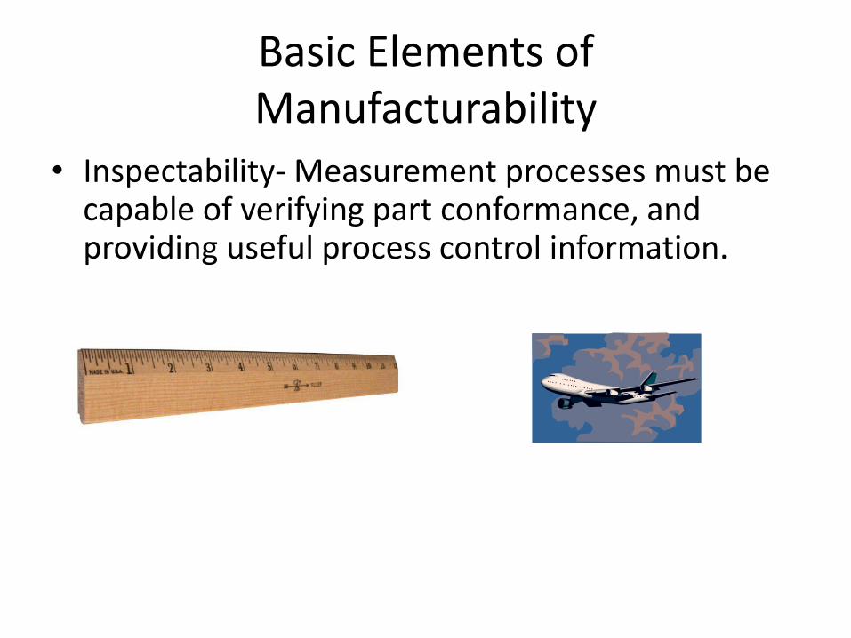
• Inspectability- Measurement processes must be capable of verifying part conformance, and providing useful process control information.

Basic Elements of Manufacturability
• What options do you have if a design isn’t producible?
– Find a more capable process if possible.
– The cost will probably rise, but the product can be made.

Basic Elements of Manufacturability
• What options do you have if a design isn’t inspectable?
– Find a more capable inspection method.
– The cost will probably rise, but the product can be verified.

Basic Elements of Manufacturability
What options do you have if a design doesn’t function?

Basic Elements of Manufacturability
What options do you have if a design doesn’t function?
GD&T
• What is it?

GD&T
• What is it?
• Why is it?

GD&T
• What is it?
• Why is it?
• What does it have to do with Manufacturability?

GD&T
• What is it?
• Why is it?
• What does it have to do with Manufacturability?
• How can we use GD&T to improve Manufacturability?

GD&T
• What is it?
• Geometric Dimensioning and Tolerancing is recognized around the word as the only effective way to define part geometry.

GD&T
• What is it? ASME Y14.5M 2009
• A concise language used on engineering documentation to provide one clear definition of mechanical parts.

GD&T
• What is it?
• GD&T has its own Symbols

GD&T
• What is it?
• GD&T has its own Rules
• They are NOT OPEN to INTERPRETATION
GD&T
• What is it?
• GD&T has its own Rules
• They are NOT OPEN to INTERPRETATION

GD&T
• What is it?
• GD&T has its own Symbols
• GD&T has its own Rules
• GD&T has its own Vocabulary

GD&T
• Why is it?
• Prior to the advent of GD&T there several drawbacks to the way parts were dimensioned.
GD&T • Why is it?
• Confusion over how to set up the part for production / measurement.

GD&T • Why is it?
• Confusion over how to set up the part for production / measurement.
• Unwanted tolerance accumulation.

GD&T • Why is it?
• Confusion over how to set up the part for production / measurement.
• Unwanted tolerance accumulation.
• Tolerancing of points in space that may not be measured, such as the center of a radius.

GD&T
• Why is it?
• Confusion over how to set up the part for production / measurement.
• Unwanted tolerance accumulation.
• Tolerancing of points in space that may not be measured, such as the center of a radius.
• Wedge and square shaped tolerance zones.
GD&T
• What does it have to do with Manufacturability?

GD&T • What does it have to do with
Manufacturability?
• Thoughtful use of GD&T creates a specification that meets design requirements in terms of form, fit, and function.

GD&T • What does it have to do with
Manufacturability?
• Thoughtful use of GD&T creates a specification that the manufacturing team can meet with available technology and at a cost that allows for an acceptable profit margin.

GD&T • What does it have to do with
Manufacturability?
• Thoughtful use of GD&T creates a specification that can be accurately verified by existing measurement technology, providing product conformance and process control information.

GD&T
• How can we use GD&T to improve Manufacturability?
• Maximizing Production Tolerances
• As the tolerance goes up, the cost goes down
• GD&T maximizes tolerances without sacrificing product quality
• GD&T also makes tolerance analysis possible

GD&T
• How can we use GD&T to improve Manufacturability?
• Select Your Datums Based Upon Function - Not Production • Often production complains about the datum features selected. In
general, datum features should be selected based on function-not on how the part will be produced. Two datum reference frames are used on the part shown below. The datum reference frame established by datum features A, B and C was selected because these are the features that locate and orient the bracket. From this datum reference frame the features used to locate and orient the module are located. The auxiliary datum reference frame D, E, A could then be established to position the four mounting holes. This approach to selecting datum features is functional and will usually result in the least variation in the assembly at the lowest cost. It is then up to production to use their skill, knowledge and expertise to produce an in-spec part. Besides, most Production folks will tell you they really don’t want the Design folks telling them how to make parts.

GD&T • How can we use GD&T to improve Manufacturability?
• Select Your Datums Based Upon Function - Not Production
GD&T • How can we use GD&T to improve Manufacturability?
• Datums Must Be of Sufficient Size (in accordance with Y14.5M-1994 standard)
• When discussing parts like the one shown below often people ask why datum A is referenced in the position callout. After all, the hole locating dimensions are from B and C. One reason to include A is to control the perpendicularity of the four holes. Since the part is so thin it is unlikely that the holes would ever fail the positional requirement because they were tipped too much relative to datum A. A more important reason to include A as a datum reference is to assure a stable setup for inspection of the part. A planar primary datum takes away 3 degrees of freedom. B is too narrow to reproducibly take away more than 2 degrees of freedom. It is not "sufficient in size to permit its use" (section 4.3 of the Y14.5 standard), in this case as a primary datum feature. A major purpose for selecting the correct datum features is to assure reproducible inspection of parts. Datum A is sufficient in size (area) to accomplish this. Using datum features B or C as a primary datum would be like trying to balance a credit card on its edge.

GD&T • How can we use GD&T to improve Manufacturability? • Datums Must Be of Sufficient Size
(in accordance with Y14.5M-1994 standard)

GD&T • How can we use GD&T to improve Manufacturability? • Time to Stop the Nonsense •
(in accordance with Y14.5M-1994 standard) • If you don’t have opposed points (180+ degrees of arc), you cannot reproducibly
find the center (axis) of a radius. Often a curved surface will be defined on a drawing by locating the center and specifying a radius. There is nothing wrong with this type of dimensioning. The problem is that traditionally these dimensions are toleranced directly or use the title block tolerance. Once the part is made, someone has to determine where the center is out in space to determine if the dimensions are in tolerance.
• When you have opposed points, you can contact these points with an indicator or gage pin and calculate the location of the center. Without opposed points, you have to try to fit a radius to the surface and try to determine where the center is. If you are taking sample points with a CMM or vision system, you will get an answer; but, if the radius is not perfectly round (and it never will be), contacting different points will yield a different size radius with a different center location.
• The problem of Least Squares.

GD&T • How can we use GD&T to improve
Manufacturability? • Time to Stop the Nonsense

GD&T • How can we use GD&T to improve
Manufacturability? • Time to Stop the Nonsense

GD&T • The Problem of Least Squares Determine the minimum and maximum effective radii given a nominal radius, tolerance zone, and angular segment
Helps explain why using a radius gage or CMM arc extrapolation (< 180°) may provide misleading results when the feature actually exists within the tolerance zone.
A negative maximum radius value indicates the shape has collapsed and inverted (concave ↔ convex)
Arc centerline aligned with Y axis
Tested to ≤ 180°
Math from p.154 "Machinery's Handbook", 21st edition, 'Areas and Dimensions of Plane Figures - Circular Segment'
Nominal Radius 0.015
Bilateral Tolerance (±) 0.003
Included Angle 90
Minimum Radius 0.00854097
Maximum Radius -0.11163961
Range -0.1201806
Workup min r max r
r 0.012 0.018
h 0.00951472 -0.00072792
c 0.01697056 0.02545584
x y y2
rn left -0.0106066 0.0106066 -0.002636039
rn center 0 0.015 0.001757359
rn right 0.0106066 0.0106066 -0.002636039
uptol left -0.01272792 0.01272792 -0.000514719
uptol center 0 0.018 0.004757359
uptol right 0.01272792 0.01272792 -0.000514719
lwtol left -0.00848528 0.00848528 -0.004757359
lwtol center 0 0.012 -0.001242641
lwtol right 0.00848528 0.00848528 -0.004757359
minr left -0.00848528 0.00848528 -0.004757359
minr center 0 0.018 0.004757359
minr right 0.00848528 0.00848528 -0.004757359
maxr left -0.01272792 0.01272792 -0.000514719
maxr center 0 0.012 -0.001242641
maxr right 0.01272792 0.01272792 -0.000514719
min -0.0127279 0.00848528 -0.004757359
max 0.01272792 0.018 0.004757359
mean 0 0.01324264 0
Chart Stuff
-0.01
0.00
0.00
0.00
0.00
0.00
0.01
-0.02 -0.01 -0.01 0.00 0.01 0.01 0.02
Y
X
Radius Tolerance Envelope
Nominal UpTol LowTol MinRad MaxRad
Nominal UpTol LowTol MinRad MaxRad

GD&T • Some Pitfalls and Red Flags
• Fully constrained features -

GD&T • Some Pitfalls and Red Flags
• Fully constrained features – There is NO requirement that all features have references to Three Datums.
• Datum reference frames should reflect the function of the feature.
• Unnecessary Constraint = Unnecessary Cost
GD&T • Some Pitfalls and Red Flags
• Fully constrained features –
• Datums should reflect product function

GD&T • Some Pitfalls and Red Flags
• Fully constrained features –
• Datums should reflect product function
• Features should only be constrained by datums that relate to the function of the feature.

GD&T • Some Pitfalls and Red Flags
• All features are at Regardless of Feature Size-
• Take advantage of Datum features of size.
• Maximum or minimum material condition can improve manufacturability without adversely affecting part function or quality.

GD&T • Some Pitfalls and Red Flags
• Surfaces and Features of Size such as Cylinders, Cones, Spheres, are calculated as Least Squares geometries.
• Use Maximum Inscribed and Minimum Circumscribed calculations for these features.
• The “pin gage” and “ring gage” size.

GD&T • Some Pitfalls and Red Flags
• Radii dimensioned directly with small arc segments.
• Very difficult to calculate accurately and repeatedly.
• Use Profile tolerance.

GD&T
• What’s the catch?
GD&T
• What’s the catch?
• CMMs are not able to perform the math required to give the results true to Y14.5.
• You’ve probably seen evidence of this…

GD&T • You’ve probably seen evidence of this…
• Manufacturing makes a part they believe is in tolerance.

GD&T • You’ve probably seen evidence of this…
• Quality measures the part on the CMM

GD&T • You’ve probably seen evidence of this…
• Quality rejects the part as out of tolerance.

GD&T • You’ve probably seen evidence of this…
• The part is checked on a surface plate and appears to be in tolerance.

GD&T • You’ve probably seen evidence of this…
• The CMM is recalibrated.

GD&T • You’ve probably seen evidence of this…
• The part Still measures out of tolerance.
• Now the CMM guy is confused too.
GD&T
• NOW WHAT ???

GD&T
SmartProfile
• GD&T Fitting software capable of applying your measured data to the model in a manner that is COMPLIANT to Y14.5

GD&T
SmartProfile
GOOD PART !
SmartProfile allows the CMM measurements to take maximum advantage of the tolerance given by the design team.

Some Examples
SmartProfile

Questions?
Thank You !