GCC vinyl cutter, cutting plotter for sign making€¦ · GCC vinyl cutter, cutting plotter for...
15
2/4/13 7:57 PM GCC vinyl cutter, cutting plotter for sign making Page 1 of 15 http://www.gccworld.com/pro_cutter_soft_DirectCut.html#2 Plotter Setup In "Plotter Setup," you can choose "Plotter List," "Environment," "Pen," and so on. [Plotter list] In this area, you can choose the machine type and set some basic information for your plotter such as the plotting area. The screen below shows ten cutting plotter models. As shown above, the machine type displayed with a green check button represents the default plotter. You can click the button to enable or disable the plotter as well as double-click the name of the machine type to set the machine information. [The Plotter setup Screen] Double-clicking name of the cutting plotter will display the dialog below. The information shown here varies according to the model you have selected. Text outline This tool outlines letters. All letters must be outlined through this tool to generate output data. ① Choose the letters that you want outlined. ② Choose the Text outline command and a contour line will be created for your image.
Transcript of GCC vinyl cutter, cutting plotter for sign making€¦ · GCC vinyl cutter, cutting plotter for...
2/4/13 7:57 PMGCC vinyl cutter, cutting plotter for sign making
Page 1 of 15http://www.gccworld.com/pro_cutter_soft_DirectCut.html#2
Plotter Setup
In "Plotter Setup," you can choose "Plotter List," "Environment," "Pen," and so on.
[Plotter list] In this area, you can choose the machine type and set some basic information for your plotter such as the plotting area.The screen below shows ten cutting plotter models.
As shown above, the machine type displayed with a green check button represents the default plotter. You can click the button toenable or disable the plotter as well as double-click the name of the machine type to set the machine information.
[The Plotter setup Screen]Double-clicking name of the cutting plotter will display the dialog below. The information shown here varies according to the model you have selected.
Text outline
This tool outlines letters.
All letters must be outlined through this tool to generate output data. ① Choose the letters that you want outlined.② Choose the Text outline command and a contour line will be created for your image.
2/4/13 7:57 PMGCC vinyl cutter, cutting plotter for sign making
Page 2 of 15http://www.gccworld.com/pro_cutter_soft_DirectCut.html#2
Note:
The line width must be set as 0.001 mm[Text outline] must be applied first before applying [Make outline and offset]
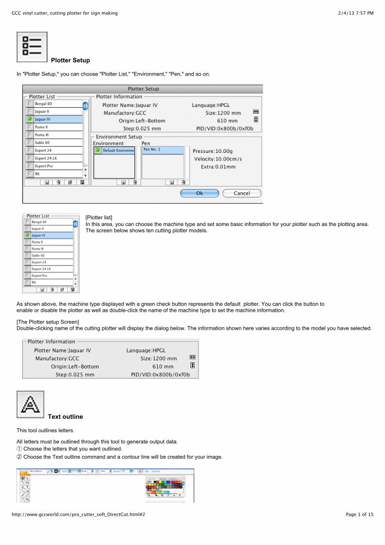
Make outline and offset
Extracts outlines of graphics.① Choose a graphic from which to extract an outline.② Choose the Make outline and offset command.③ Enter the amount of offset and then click “OK” when the “Expand” window is presented.
* If you want to use the previous offset value asit is, you need to shift-click.
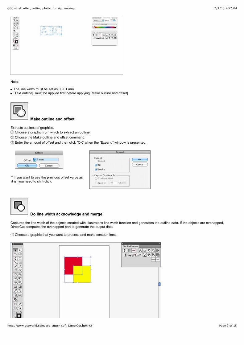
Do line width acknowledge and merge
Captures the line width of the objects created with Illustrator's line width function and generates the outline data. If the objects are overlapped,DirectCut computes the overlapped part to generate the output data.
① Choose a graphic that you want to process and make contour lines.
2/4/13 7:57 PMGCC vinyl cutter, cutting plotter for sign making
Page 3 of 15http://www.gccworld.com/pro_cutter_soft_DirectCut.html#2
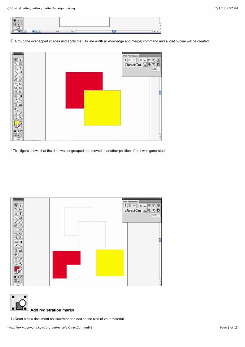
② Group the overlapped images and apply the [Do line width acknowledge and merge] command and a joint outline will be created.
* This figure shows that the data was ungrouped and moved to another position after it was generated.
Add registration marks
1) Open a new document on Illustrator and decide the size of your material.
2/4/13 7:57 PMGCC vinyl cutter, cutting plotter for sign making
Page 4 of 15http://www.gccworld.com/pro_cutter_soft_DirectCut.html#2
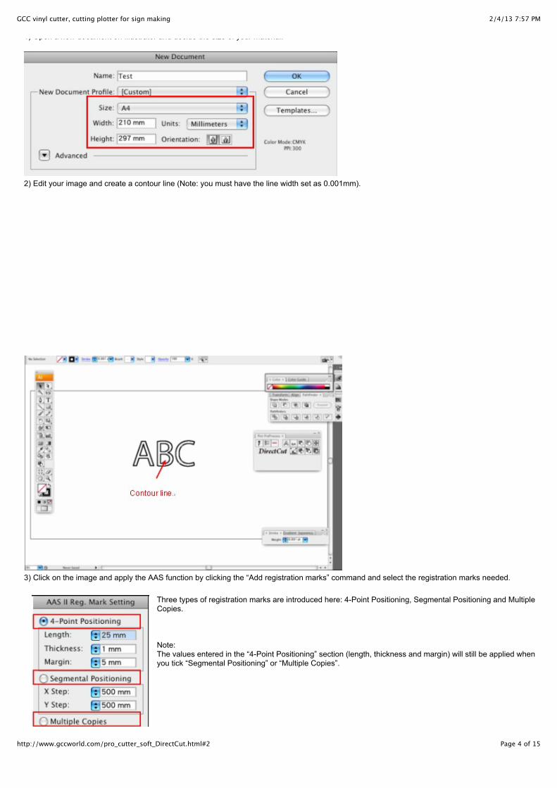
1) Open a new document on Illustrator and decide the size of your material.
2) Edit your image and create a contour line (Note: you must have the line width set as 0.001mm).
3) Click on the image and apply the AAS function by clicking the “Add registration marks” command and select the registration marks needed.
Three types of registration marks are introduced here: 4-Point Positioning, Segmental Positioning and MultipleCopies.
Note: The values entered in the “4-Point Positioning” section (length, thickness and margin) will still be applied whenyou tick “Segmental Positioning” or “Multiple Copies”.
2/4/13 7:57 PMGCC vinyl cutter, cutting plotter for sign making
Page 5 of 15http://www.gccworld.com/pro_cutter_soft_DirectCut.html#2
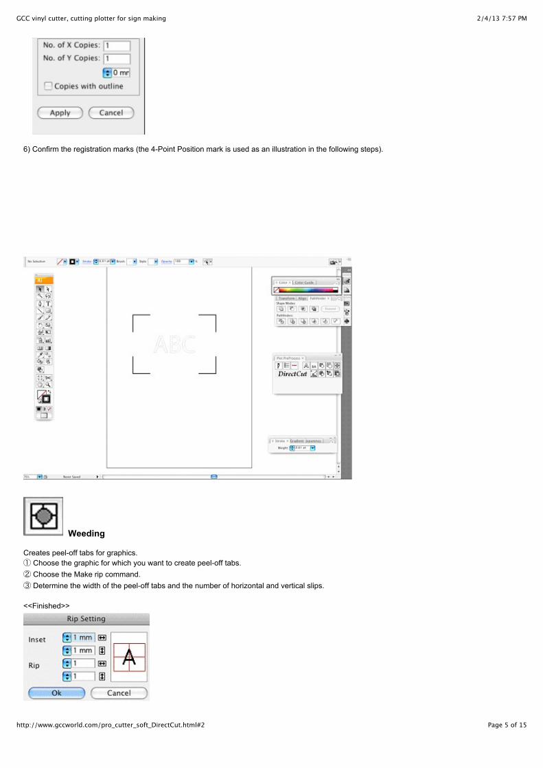
6) Confirm the registration marks (the 4-Point Position mark is used as an illustration in the following steps).
Weeding
Creates peel-off tabs for graphics.① Choose the graphic for which you want to create peel-off tabs.② Choose the Make rip command.③ Determine the width of the peel-off tabs and the number of horizontal and vertical slips.
<<Finished>>

2/4/13 7:57 PMGCC vinyl cutter, cutting plotter for sign making
Page 6 of 15http://www.gccworld.com/pro_cutter_soft_DirectCut.html#2
* If you want to use the previous setting as it is, you need to shift-click.
*This command creates peel-off tabs on large objects, enabling users to peel them off from the materials easily.
Split plot data
Creates overlaps ("flaps" to be pasted together) and auto-split lines when splitting up an output. This command divides a large object into severalsegments when cutting. These segments are then combined to create the entire image. ① Choose the graphic that you want to split up.② Choose the Split plot data tool. ③ Click on the position where you want to split the data. Shift-clicking at this point will split the data vertically on the screen, while normal clicking will do so horizontally.④ Split lines appear. ⑤ Determine the shape and the size of the flaps in the dialog box.
2/4/13 7:57 PMGCC vinyl cutter, cutting plotter for sign making
Page 7 of 15http://www.gccworld.com/pro_cutter_soft_DirectCut.html#2
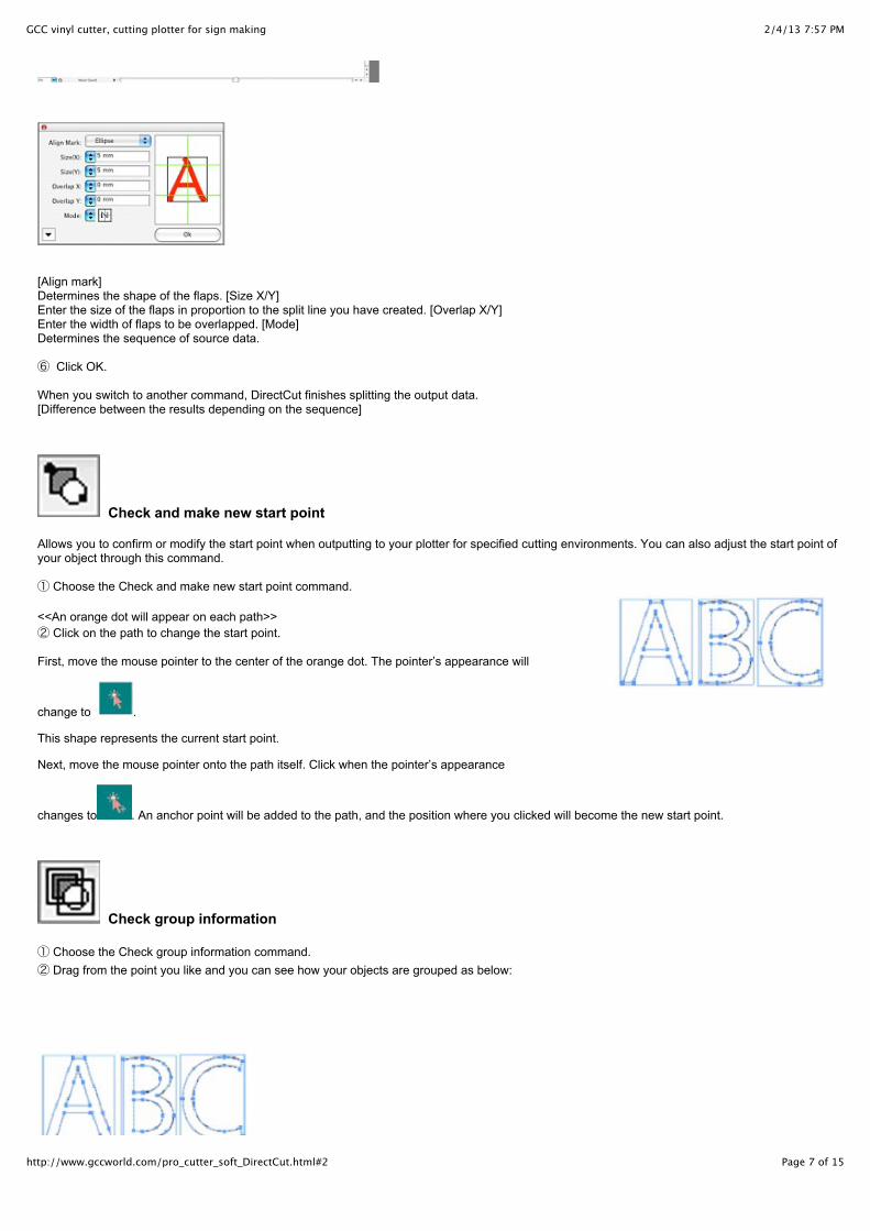
[Align mark]Determines the shape of the flaps. [Size X/Y]Enter the size of the flaps in proportion to the split line you have created. [Overlap X/Y]Enter the width of flaps to be overlapped. [Mode]Determines the sequence of source data.
⑥ Click OK.
When you switch to another command, DirectCut finishes splitting the output data. [Difference between the results depending on the sequence]
Check and make new start point
Allows you to confirm or modify the start point when outputting to your plotter for specified cutting environments. You can also adjust the start point ofyour object through this command.
① Choose the Check and make new start point command.
<<An orange dot will appear on each path>>② Click on the path to change the start point.
First, move the mouse pointer to the center of the orange dot. The pointer’s appearance will
change to .
This shape represents the current start point.
Next, move the mouse pointer onto the path itself. Click when the pointer’s appearance
changes to . An anchor point will be added to the path, and the position where you clicked will become the new start point.
Check group information
① Choose the Check group information command.② Drag from the point you like and you can see how your objects are grouped as below:
2/4/13 7:57 PMGCC vinyl cutter, cutting plotter for sign making
Page 8 of 15http://www.gccworld.com/pro_cutter_soft_DirectCut.html#2
* In step ②, dragging while pressing the Shift key enables you to zoom.
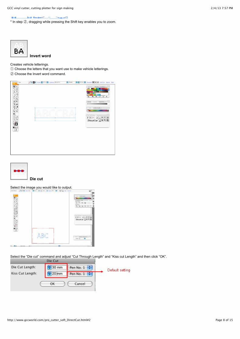
Invert word
Creates vehicle letterings.① Choose the letters that you want use to make vehicle letterings.② Choose the Invert word command.
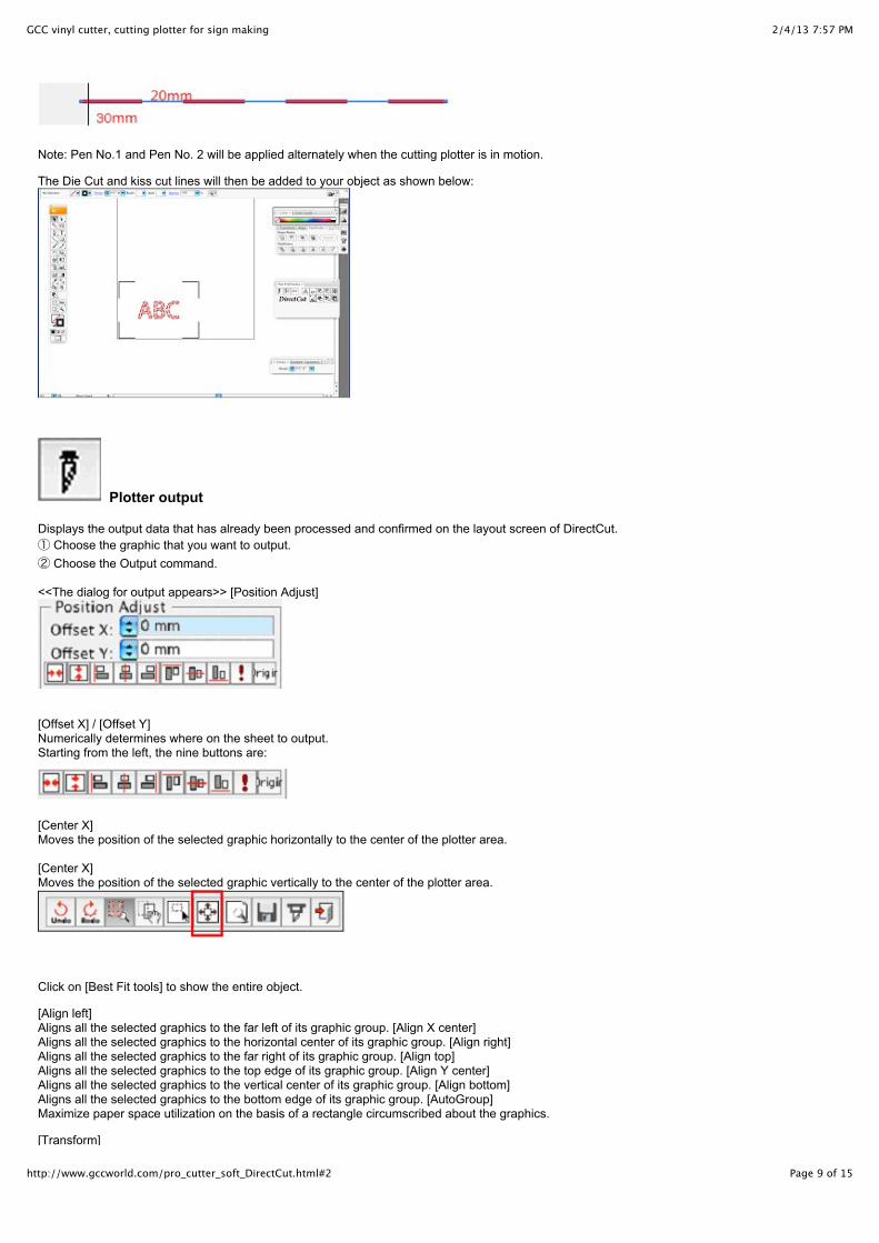
Die cut
Select the image you would like to output.
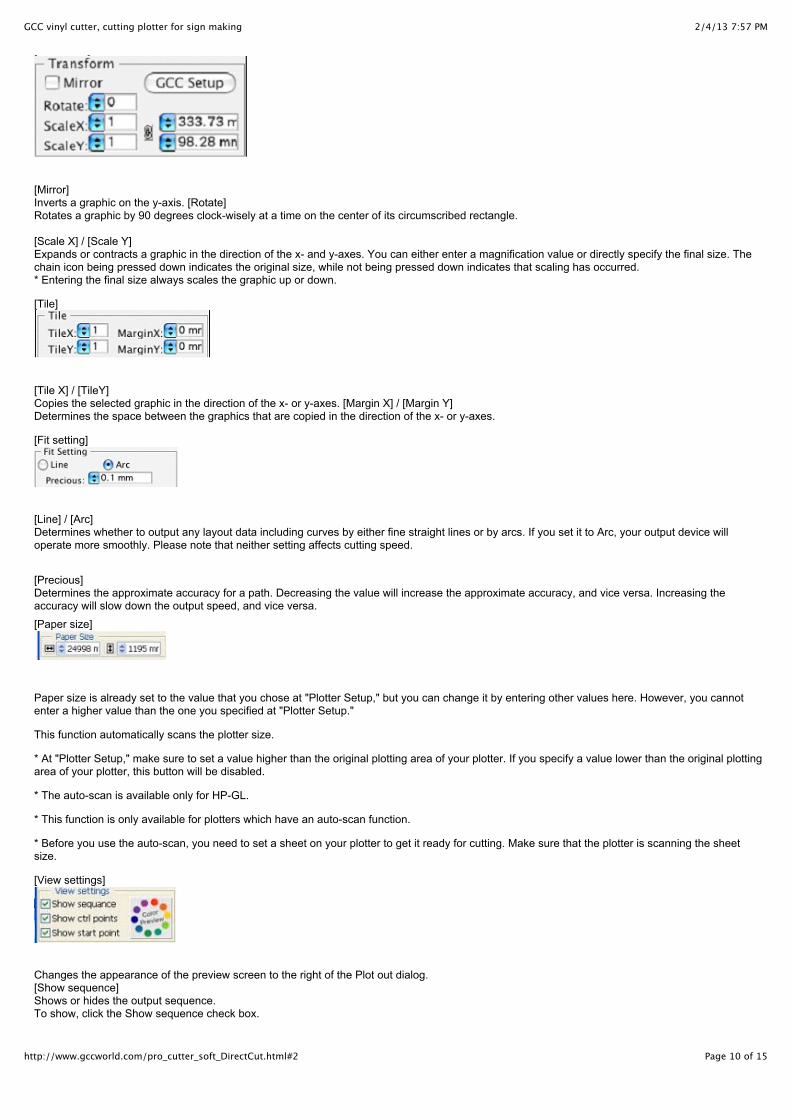
Select the “Die cut” command and adjust “Cut Through Length” and “Kiss cut Length” and then click “OK”.
2/4/13 7:57 PMGCC vinyl cutter, cutting plotter for sign making
Page 9 of 15http://www.gccworld.com/pro_cutter_soft_DirectCut.html#2
Note: Pen No.1 and Pen No. 2 will be applied alternately when the cutting plotter is in motion.
The Die Cut and kiss cut lines will then be added to your object as shown below:
Plotter output
Displays the output data that has already been processed and confirmed on the layout screen of DirectCut.① Choose the graphic that you want to output.② Choose the Output command.
<<The dialog for output appears>> [Position Adjust]
[Offset X] / [Offset Y] Numerically determines where on the sheet to output. Starting from the left, the nine buttons are:
[Center X] Moves the position of the selected graphic horizontally to the center of the plotter area.
[Center X] Moves the position of the selected graphic vertically to the center of the plotter area.
Click on [Best Fit tools] to show the entire object.
[Align left]Aligns all the selected graphics to the far left of its graphic group. [Align X center]Aligns all the selected graphics to the horizontal center of its graphic group. [Align right]Aligns all the selected graphics to the far right of its graphic group. [Align top]Aligns all the selected graphics to the top edge of its graphic group. [Align Y center]Aligns all the selected graphics to the vertical center of its graphic group. [Align bottom]Aligns all the selected graphics to the bottom edge of its graphic group. [AutoGroup] Maximize paper space utilization on the basis of a rectangle circumscribed about the graphics.
[Transform]
2/4/13 7:57 PMGCC vinyl cutter, cutting plotter for sign making
Page 10 of 15http://www.gccworld.com/pro_cutter_soft_DirectCut.html#2
[Transform]
[Mirror]Inverts a graphic on the y-axis. [Rotate]Rotates a graphic by 90 degrees clock-wisely at a time on the center of its circumscribed rectangle.
[Scale X] / [Scale Y] Expands or contracts a graphic in the direction of the x- and y-axes. You can either enter a magnification value or directly specify the final size. Thechain icon being pressed down indicates the original size, while not being pressed down indicates that scaling has occurred.* Entering the final size always scales the graphic up or down.
[Tile]
[Tile X] / [TileY]Copies the selected graphic in the direction of the x- or y-axes. [Margin X] / [Margin Y]Determines the space between the graphics that are copied in the direction of the x- or y-axes.
[Fit setting]
[Line] / [Arc]Determines whether to output any layout data including curves by either fine straight lines or by arcs. If you set it to Arc, your output device willoperate more smoothly. Please note that neither setting affects cutting speed.
[Precious]Determines the approximate accuracy for a path. Decreasing the value will increase the approximate accuracy, and vice versa. Increasing theaccuracy will slow down the output speed, and vice versa.
[Paper size]
Paper size is already set to the value that you chose at "Plotter Setup," but you can change it by entering other values here. However, you cannotenter a higher value than the one you specified at "Plotter Setup."
This function automatically scans the plotter size.
* At "Plotter Setup," make sure to set a value higher than the original plotting area of your plotter. If you specify a value lower than the original plottingarea of your plotter, this button will be disabled.
* The auto-scan is available only for HP-GL.
* This function is only available for plotters which have an auto-scan function.
* Before you use the auto-scan, you need to set a sheet on your plotter to get it ready for cutting. Make sure that the plotter is scanning the sheetsize.
[View settings]
Changes the appearance of the preview screen to the right of the Plot out dialog. [Show sequence]Shows or hides the output sequence.To show, click the Show sequence check box.
[Show ctrl points]
2/4/13 7:57 PMGCC vinyl cutter, cutting plotter for sign making
Page 11 of 15http://www.gccworld.com/pro_cutter_soft_DirectCut.html#2
[Show ctrl points]Shows or hides the control points.
To show, click the Show ctrl points check box.
[Show start points]Shows or hides the output start points.
To show, click the Show start points check box.
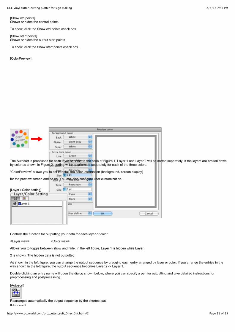
[ColorPreview]
The Autosort is processed for each layer or color. In the case of Figure 1, Layer 1 and Layer 2 will be sorted separately. If the layers are broken downby color as shown in Figure 2, sorting will be performed separately for each of the three colors.
"ColorPreview" allows you to set in detail the color information (background, screen display)
for the preview screen and so on. You can also configure user customization.
[Layer / Color setting]
Controls the function for outputting your data for each layer or color.
<Layer view> <Color view>
Allows you to toggle between show and hide. In the left figure, Layer 1 is hidden while Layer
2 is shown. The hidden data is not outputted.
As shown in the left figure, you can change the output sequence by dragging each entry arranged by layer or color. If you arrange the entries in theway shown in the left figure, the output sequence becomes Layer 2 -> Layer 1.
Double-clicking an entry name will open the dialog shown below, where you can specify a pen for outputting and give detailed instructions forpreprocessing and postprocessing.
[Autosort]
Rearranges automatically the output sequence by the shortest cut.[Manusort]
2/4/13 7:57 PMGCC vinyl cutter, cutting plotter for sign making
Page 12 of 15http://www.gccworld.com/pro_cutter_soft_DirectCut.html#2
[Manusort]
Rearranges the output sequence in ascending order by specifying the inside of a group. Specifying the outside of the graphics will finish manualsorting.[Exchange sort]
Specifies two groups in order to alternate their output sequence.
* Manual sorting and Exchange sort will be performed separately for each layer or color that is currently selected. For example, if you perform manualsorting with Layer 3 selected as shown in Figure 3, the preview screen will display only the elements of Layer 3. If none of the layers are selected, thetop layer (e.g., Layer 3 in Figure 3) will be the target for manual sorting.
[Undo]
Cancels the current operation on [Plotter Output] and goes back to the previous one.
[Redo]
Restores the canceled operation.
[Zoom tools]
Dragging from top left to bottom right with your mouse will scale up the data within the selected area, while dragging from bottom right to top left willscale down the data. Simply clicking on the data will reset the magnification to "x1."
[Move tools]
Allows you to grab the paper and move it to other positions by dragging.
[Select tools]
Selects the object in the preview screen. The selected data turns green. You can either rubber-band select multiple object by dragging or select eachsingle objects by clicking. To deselect the object that you have selected, just shift-click it.
[Best fit tools]
Displays all the graphics at once within the domain of the preview screen.
[Plot preview]
Allows for on-screen simulation of the commands and the behavior that DirectCut will output.
2/4/13 7:57 PMGCC vinyl cutter, cutting plotter for sign making
Page 13 of 15http://www.gccworld.com/pro_cutter_soft_DirectCut.html#2
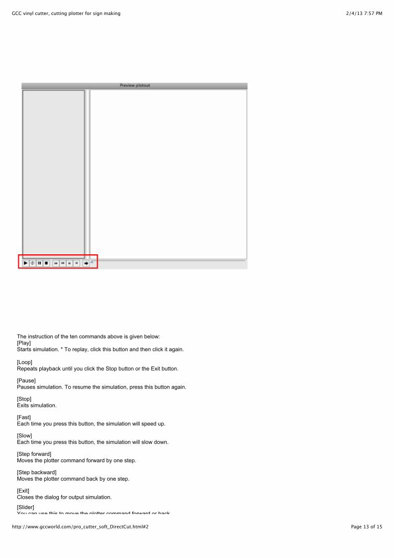
The instruction of the ten commands above is given below:[Play]Starts simulation. * To replay, click this button and then click it again.
[Loop]Repeats playback until you click the Stop button or the Exit button.
[Pause] Pauses simulation. To resume the simulation, press this button again.
[Stop]Exits simulation.
[Fast]Each time you press this button, the simulation will speed up.
[Slow]Each time you press this button, the simulation will slow down.
[Step forward]Moves the plotter command forward by one step.
[Step backward]Moves the plotter command back by one step.
[Exit]Closes the dialog for output simulation.
[Slider]You can use this to move the plotter command forward or back.
2/4/13 7:57 PMGCC vinyl cutter, cutting plotter for sign making
Page 14 of 15http://www.gccworld.com/pro_cutter_soft_DirectCut.html#2
You can use this to move the plotter command forward or back.
[Make plot file]
Allows you to name the output data file and save it.
[Export]
Allows DirectCut to output to your output device.
[Exit]
Closes this dialog.
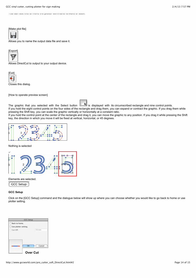
[How to operate preview screen]
The graphic that you selected with the Select button is displayed with its circumscribed rectangle and nine control points.If you hold the eight control points on the four sides of the rectangle and drag them, you can expand or contract the graphic. If you drag them whilepressing the Shift key, you can scale the graphic vertically or horizontally at a constant ratio.If you hold the control point at the center of the rectangle and drag it, you can move the graphic to any position. If you drag it while pressing the Shiftkey, the direction in which you move it will be fixed at vertical, horizontal, or 45 degrees.
Nothing is selected
Elements are selected.
GCC Setup
Click on the [GCC Setup] command and the dialogue below will show up where you can choose whether you would like to go back to home or useplotter setting.
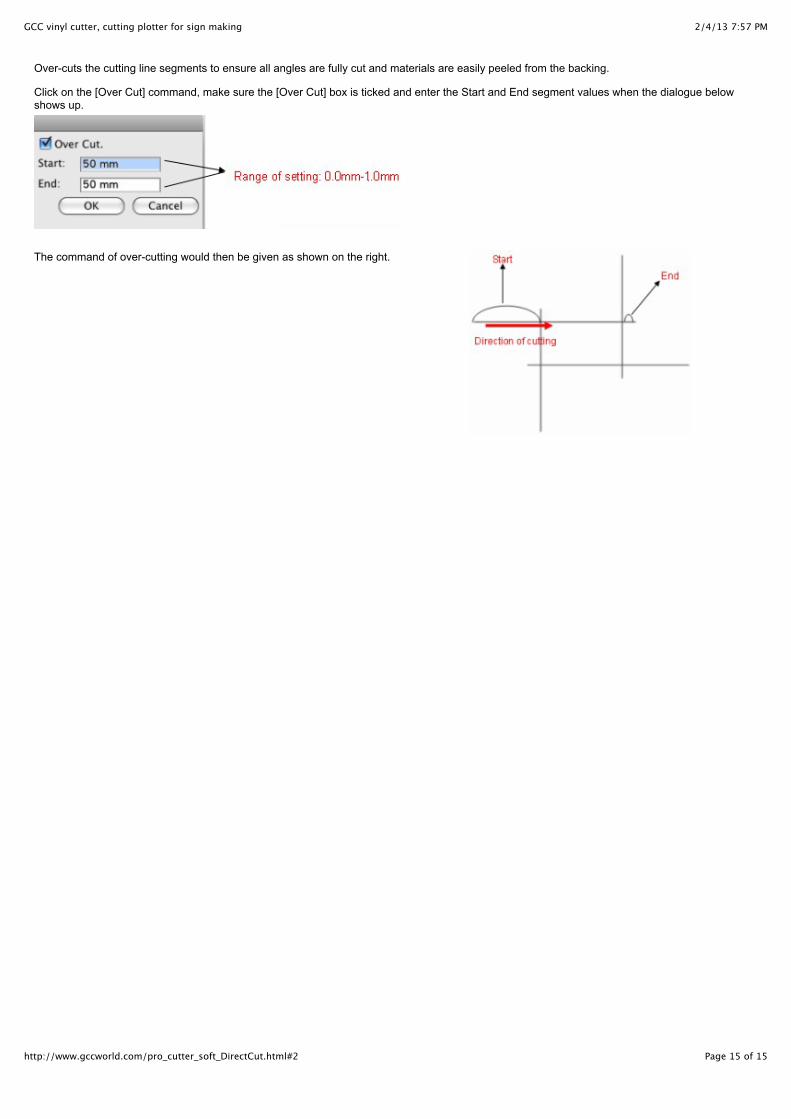
Over Cut
2/4/13 7:57 PMGCC vinyl cutter, cutting plotter for sign making
Page 15 of 15http://www.gccworld.com/pro_cutter_soft_DirectCut.html#2
Over-cuts the cutting line segments to ensure all angles are fully cut and materials are easily peeled from the backing.
Click on the [Over Cut] command, make sure the [Over Cut] box is ticked and enter the Start and End segment values when the dialogue belowshows up.
The command of over-cutting would then be given as shown on the right.