Gaze Ma Nip La Ti On
8
Gaze Manipulation for One-to-one Teleconferencing A. Criminisi, J. Shotton, A. Bl ake, P .H.S. Torr Microsoft Research Ltd, Cambridge, UK Abstract A new algorit hm is pro posed for novel view generat ion in one-to- one teleconfer encing applica tions. Given the video streams ac- quired by two cameras placed on either side of a computer moni- tor, the proposed algorithm synthesises images from a virtual cam- era in arbitrary position (typically located within the monitor) to facilitate eye contact. Our t echn iq ue is ba sed on an impr ov ed , dy na m ic - pr ogr amming, stere o algorit hm for efficien t nov el-v iew gen- erati on. The two main contrib utions of this paper ar e: i) a new type of three-plane graph for dense-stereo dynamic-programming, that encourages correct occlusion labeling; ii) a compact geomet- ric derivation for novel-view synthesis by direct projection of the minimum-cost surface. Further mor e, this paper presents a novel algorithm for the temporal maintenance of a background model to enhanc e the re nde ring of occl usi ons and re duc e temp ora l artefacts (flicker); and a cost aggre gation algorithm that acts directly on our three-dimensional matching cost space. Examples are given that demonstrate the robustness of the new algorithm to spatial and temporal artefacts for long stereo video streams. These include demonstr ations of synthes is of cyclopea n views of extend ed con versat ional sequences . We further demon- strate synthesis from a freely translating virtual camera. 1. Intr oduct ion This paper addresses the problem of novel-view synthesis from a pair of rectified images with specific emphasis on peer-to-peer teleconferencing. With the rise of instant mes- senging technologies, it is envisaged that the PC will in- crea sing ly be used for inte ract iv e visu al communic ation . One pressing problem is that any camera used to capture images of one of the participants has to be positioned offset to his or her gaze. This can lead to lack of eye contact and hence undesirable effects on the interaction [4]. Pre viously proposed solutions to this problem can be broadly categorized as model-based or image-based . On e model-based approach is to use a detailed head model and reproject it into the cyclopean view; whilst this can be suc- cessful [10, 11], it is limited to imaging heads, and would not, for example, deal with a hand in front of the face or whiteboard scribbli ng. A more general approach therefore is to use low level stereo matching, in some form, and fol- low with an image based rendering approach ( IBR) [1]. The Input right image Input left image Left camera Computer screen Right camera Messenging window Figure 1: Camera configuration. The basic setup considers two cam- eras placed on the frame of the computer monitor. The goal of this paper is that of generating high-quality images for virtual cameras placed anywhere near the comp uter moni tor . It willbe demon strat ed t hat gaze corre ctio n ca n be achieved by this technique in an efficient and compelling way. aim is to synthesize a view from a virtual camera that is lo- cated roughly where the image of the head will be displayed on the screen for each participant, thus achieving eye con- tact. The basic setup is illustrated in fig. 1. In IBR a depth map is combined with an image to pro- duce the new view. However in our approach we use a new min-cost surface projection algorithm for novel view gener- ation that deals with occlusions and hole filling in a direct manner; by avoiding the explicit construction of the scene 3D model. In order to generate a depth map a dense stereo algo- rit hm is req uired, a sub sta nti al re vie w of whi ch canbe found in [8]. According to the evaluation, two of the most power- ful approaches use graph cuts [5, 7] and loopy belief prop- agation [9] but both of these are currently too computation- ally intens iv e for real time appl icat ions. Furt hermore, the eval ua ti on in [8] ma y not be vali d for our purposes as : (i ) the range of disparities considered in this paper is much smaller than in our application (0-29 pixels there, whereas we typ- ically consider 0-80 pixel disparities), (ii) we are primarily interested in new view synthesis, thus it does not matter if the disparities are relatively inaccurate in homogeneous im- age regions, all that matters is that the new view is well synthesized. On the other hand where occlusions occur it is important to estimate them accurately since otherwise arte- facts such as “haloing” (a lens-like distortion around fore- gro und obj ect s) bec ome vis ibl e. (ii i) we con sid er lon g vid eo seque nces, thus stabi lity of estimat ion also plays a part: a flick ery recon stru ctio n is less desirab le than a cons iste nt one. One of the most computationally efficient algorithms for stereo is Epipolar line Dynamic Programming [6], referred to as DP. We have implemented DP for dense stereo [3], 1
-
Upload
sungjin-hong -
Category
Documents
-
view
216 -
download
0
Transcript of Gaze Ma Nip La Ti On

8/3/2019 Gaze Ma Nip La Ti On
http://slidepdf.com/reader/full/gaze-ma-nip-la-ti-on 1/8
Gaze Manipulation for One-to-one Teleconferencing
A. Criminisi, J. Shotton, A. Blake, P.H.S. Torr
Microsoft Research Ltd, Cambridge, UK
Abstract
A new algorithm is proposed for novel view generation in one-to-
one teleconferencing applications. Given the video streams ac-
quired by two cameras placed on either side of a computer moni-
tor, the proposed algorithm synthesises images from a virtual cam-
era in arbitrary position (typically located within the monitor) to
facilitate eye contact.
Our technique is based on an improved, dynamic-
programming, stereo algorithm for efficient novel-view gen-
eration. The two main contributions of this paper are: i) a newtype of three-plane graph for dense-stereo dynamic-programming,
that encourages correct occlusion labeling; ii) a compact geomet-
ric derivation for novel-view synthesis by direct projection of the
minimum-cost surface. Furthermore, this paper presents a novel
algorithm for the temporal maintenance of a background model
to enhance the rendering of occlusions and reduce temporal
artefacts (flicker); and a cost aggregation algorithm that acts
directly on our three-dimensional matching cost space.
Examples are given that demonstrate the robustness of the new
algorithm to spatial and temporal artefacts for long stereo video
streams. These include demonstrations of synthesis of cyclopean
views of extended conversational sequences. We further demon-
strate synthesis from a freely translating virtual camera.
1. Introduction
This paper addresses the problem of novel-view synthesis
from a pair of rectified images with specific emphasis on
peer-to-peer teleconferencing. With the rise of instant mes-
senging technologies, it is envisaged that the PC will in-
creasingly be used for interactive visual communication.
One pressing problem is that any camera used to capture
images of one of the participants has to be positioned offset
to his or her gaze. This can lead to lack of eye contact and
hence undesirable effects on the interaction [4].
Previously proposed solutions to this problem can bebroadly categorized as model-based or image-based . One
model-based approach is to use a detailed head model and
reproject it into the cyclopean view; whilst this can be suc-
cessful [10, 11], it is limited to imaging heads, and would
not, for example, deal with a hand in front of the face or
whiteboard scribbling. A more general approach therefore
is to use low level stereo matching, in some form, and fol-
low with an image based rendering approach ( IBR) [1]. The
Input right imageInput left image
Left
camera
Computer
screen
Right
cameraMessenging
window
Figure 1: Camera configuration. The basic setup considers two cam-
eras placed on the frame of the computer monitor. The goal of this paper is
that of generating high-quality images for virtual cameras placed anywhere
near the computer monitor. It willbe demonstrated that gaze correction can
be achieved by this technique in an efficient and compelling way.
aim is to synthesize a view from a virtual camera that is lo-
cated roughly where the image of the head will be displayed
on the screen for each participant, thus achieving eye con-
tact. The basic setup is illustrated in fig. 1.
In IBR a depth map is combined with an image to pro-
duce the new view. However in our approach we use a new
min-cost surface projection algorithm for novel view gener-
ation that deals with occlusions and hole filling in a direct
manner; by avoiding the explicit construction of the scene
3D model.
In order to generate a depth map a dense stereo algo-
rithm is required, a substantial review of which can be foundin [8]. According to the evaluation, two of the most power-
ful approaches use graph cuts [5, 7] and loopy belief prop-
agation [9] but both of these are currently too computation-
ally intensive for real time applications. Furthermore, the
evaluation in [8] may not be valid for our purposes as: (i) the
range of disparities considered in this paper is much smaller
than in our application (0-29 pixels there, whereas we typ-
ically consider 0-80 pixel disparities), (ii) we are primarily
interested in new view synthesis, thus it does not matter if
the disparities are relatively inaccurate in homogeneous im-
age regions, all that matters is that the new view is well
synthesized. On the other hand where occlusions occur it is
important to estimate them accurately since otherwise arte-facts such as “haloing” (a lens-like distortion around fore-
ground objects) become visible. (iii) we consider long video
sequences, thus stability of estimation also plays a part: a
flickery reconstruction is less desirable than a consistent
one.
One of the most computationally efficient algorithms for
stereo is Epipolar line Dynamic Programming [6], referred
to as DP. We have implemented DP for dense stereo [3],
1

8/3/2019 Gaze Ma Nip La Ti On
http://slidepdf.com/reader/full/gaze-ma-nip-la-ti-on 2/8
a b c
Figure 2: Fast cyclopean view synthesis by dynamic programming.
(a,c) Input left and right views, respectively; (b) Cyclopean view synthe-
sized by standard dynamic programming [2]. Note that gaze is correct in
the cyclopean view. The algorithm runs at near real-time rate, but pro-
duces artefacts in the cyclopean image. In this case considerable undesired
streaks corrupt the synthesized face. Furthermore, a reconstructed tempo-
ral cyclopean sequence shows considerable flicker and also an undesirable
“halo” effect around the head.
the use of which has previously been demonstrated for cy-
clopean view interpolation [2] in video. To obtain compu-
tational efficiency, observations consist of single-pixel in-
tensities, and the consequent quality of reconstruction (es-
pecially on cluttered backgrounds) is not consistently satis-
factory, as fig. 2b shows.
Reconstruction from standard dynamic programming is
characterized by two kinds of error: (i) artefacts produced
by mismatches (horizontal streaks), and (ii) the “halo” in
the regions where the background is visible in only one of
the two input views.
This paper sets out to address and solve both kinds of
artefacts. There are two parts to our method: the first is
generating accurate disparity and occlusion maps. Indeed,
as will be seen, accurate labeling of occlusions is necessary
to remove the “haloing” effect. The second is representing
and using the computed disparities and occlusions to gen-erate a new view. Within the paper we present new con-
tributions in both areas: For the generation of disparities
we propose a new type of dynamic programming approach,
as path finding through a three-plane graph (as opposed to
the traditional single-plane DP), introducing new labels to
help the correct identification of occlusions, and altering the
cost function employed to favour: (i) correct grouping of
occlusions, (ii) formation of occlusions at the boundaries
of foreground objects, and (iii) inter scanline consistency.
Second, we introduce the elegant geometry of min-cost sur-
face projection as an efficient technique for generating syn-
thetic views from arbitrary virtual cameras directly from the
minimum-cost surface obtained during the DP process.The new algorithm is demonstrated on long sequences of
pairs of synchronized stereo videos taken from static cam-
eras, the methods show compelling novel view generation
results.
Section 2 describes traditional dynamic programming.
Section 3 introduces our improved dense stereo technique.
Our view generation approach is described in section 4, and
finally, section 5 presents concluding results.
P(X,Y,Z)
f
l r
Ol Or
X
Z
B
Y
O
Left
cameraRight
camera
Figure 3: Basic notation. P is a 3D scene point. Ol and Or are the
optical centres of left and right cameras, respectively. f is the focal length
of the cameras and B is the baseline between the two optical centres. O is
the origin of the reference X,Y,Z coordinate system.
Left scanline
R i g
h t s c a n l i n e
r
l
V i r t ua l s
c a n l i n
e
M i n i m
u m
c o s t p a
t h
Right
occluded move
M at c h e
d m ov
e
L e f t
o c c l u d e d m o
v e
lr
a b
Figure 4: Traditional dynamic programming. (a) Basic diagram for
dynamic programming. It represents the matrix of cumulative costs used
for computing the minimum cost path. (b) A single-step view of (a) show-
ing the set of the three allowed moves between pixel pairs in [2]. The
circles represent elements of the cost matrix in (a).
2. Traditional dynamic programming
In the interests of clarity this section describes briefly thebasic dynamic programming algorithm [3].
Figure 3 shows a plan view of the camera setup. The left
and right cameras provide us with the synchronized and rec-
tified input videos. f is the focal length and B the distance
between the two optical centres (baseline). A Cartesian co-
ordinate system is chosen with origin at the mid point be-
tween the left and right optical centres. In the remainder
of the paper we will refer to cyclopean images as the ones
generated by a virtual camera with optical centre in O.
Given the configuration in fig. 3 the diagram in fig. 4a
represents the cumulative cost matrix for a pair of corre-
sponding scanlines in the two input images [3].
The cost M (l, r) of matching a pixel at position l alongthe left scanline and a pixel at position r along the right
scanline is defined simply as the square difference of pixel
intensities (which in our experiment in fig. 2 is normalized
between 0 and 1). Note that, since l >= r ∀P (i.e. dispar-
ities are always positive), then it is only ever necessary to
consider the lower half of the diagram (grey in fig. 4a). The
limiting case l = r corresponds to a point at infinity with
consequent zero disparity. It is assumed from here on that
2

8/3/2019 Gaze Ma Nip La Ti On
http://slidepdf.com/reader/full/gaze-ma-nip-la-ti-on 3/8
a b
Figure 5: The 3D cost space for a pair of stereo images. (a) The
basic diagram of fig. 4a becomes a 3D diagram when all the scanline pairs
are considered. The value of each element inside the parallelepiped is the
M (l, r) cost of matching two pixels. See text for details. The diagonal
plane is called the “plane of virtual image” for reasons that will become
apparent in the remainder of the paper. (b) A 2D Gaussian filter parallel
to the virtual image plane is applied to the 3D cost space to enforce inter-
scanline consistency.
any computation is restricted in this fashion.
Apart from a simple initialization step, the elements of the cumulative cost matrix C are filled, at each iteration by
the following recurrence:
C(l, r) = min
C(l − 1, r) + OccCost
C(l − 1, r − 1) + M (l, r)C(l, r − 1) + OccCost
(1)
where C(l, r) indicates the cumulative cost of the path
reaching the point (l, r) in the matrix. This recurrence de-
fines the forward pass of the DP algorithm. Notice that
three moves (or labels) are permitted: a horizontal occluded
move, a diagonal matched move and a vertical occluded
move, respectively.The cost of having an occluded pixel, OccCost is a
manually set parameter which depends on the image pair
being examined – a value of 0.3 seems to yield the best re-
sults on a variety of images. At each iteration the minimum
cost between the three possible moves is chosen and a table
of backwards links is stored for use in the second part of DP.
The backward pass of the algorithm follows the saved links,
producing the minimum-cost path (fig. 4a) and, thereby the
disparity map.
It is important to stress the fact that only three types of
move are possible in [3] thus confounding occluded and
non-occluded moves. As described later, one of the main
contributions of this paper is that of expanding the set of permitted moves for a correct detection and classification
of the occlusion events.
3. Our improved DP algorithm
This section describes the proposed matching algorithm.
Our improved DP technique produces better occlusion clas-
sification and improved disparity maps which, in turn, yield
the removal of rendering artefacts in the synthesized virtual
images.
Computing matching costs. In order to aid inter-scanline
consistency the matching cost M (l, r) is calculated for ev-
ery pair of pixels along corresponding epipolar lines with a
windowed normalised cross-correlation: M (l, r) = ( 1 −
M (l, r))/2 where
M (l, r) =
(I L − I L)(I R − I R)
(I L − I L)2
(I R − I R)2
is the correlation coefficient. Notice that since
−1 ≤ M (l, r) ≤ +1 ∀l, r, then 0 ≤ M (l, r) ≤ 1 ∀l, r.
Taller neighborhood windows (e.g. 3× 7) help incorpo-
rate inter-scanline information better than square windows.
Computing the costs M (l, r) can be performed efficiently
by expansion of the above equation and keeping track of
sums from one pair of epipolar lines to the next.
Filtering the matching costs. The use of windows for thecomputation of the M (l, r) costs helps to reduce artefacts in
the final disparity and occlusion maps but it is not sufficient
for the complete removal of the artefacts. Therefore, in or-
der to obtain cleaner disparity and occlusion maps we first
take all the matrices of M (l, r) costs associated to each pair
of scanlines (note: not the cumulative cost matrices), stack
them up together to create a 3D cost space (fig. 5a), and then
apply a two-dimensional Gaussian smoothing filter (parallel
to the virtual image plane) to the 3D cost space. The axis
of the Gaussian kernel orthogonal to the left and right scan-
line axes (denoted a in fig. 5b) is responsible for enforcing
inter-scanline consistency of the costs and the orthogonal
axis (denoted a in fig. 5b) produces additional smoothing
of sharp corners in the occlusion map.
The output of this process is the new set of M (l, r) costs
used as input to our improved DP algorithm, described be-
low.
The five-move model. A major drawback to the stan-
dard DP approach is that slanted surfaces (e.g. non fronto-
parallel walls and table tops) in space must be approxi-
mated by a combination of diagonal (matched) and hori-
zontal or vertical (occluded) moves. In such a case the
occluded moves do not correspond to real occlusions and
therefore, in order to disambiguate between “approximat-
ing” occluded moves and real occlusions we augment thebasic 3-move model by adding a further pair of horizontal
and vertical matched moves, thus defining a 5-label (a.k.a.
5-move) model. The new model is illustrated in the diagram
in fig. 6 (to be compared with fig. 4b).
This improved model produces more consistent classifi-
cation of occluded and matched pixels. In fact, slanted sur-
faces are correctly approximated by sequences of matched
moves only, and “real” occlusion labels are correctly as-
signed to pixels visible only in one of the two input views.
3

8/3/2019 Gaze Ma Nip La Ti On
http://slidepdf.com/reader/full/gaze-ma-nip-la-ti-on 4/8
Occluded move (r)
M at c h e
d m o v
e
O c c l u d e d m o
v e ( l )
Matched move
M a
t c h e d m o
v e
lr
Figure 6: The improved 5-move model for DP. (a) Five different
moves are allowed: three matched moves (horizontal, diagonal and ver-
tical), and two occluded moves (horizontal and vertical). Thus, vertical
and horizontal moves acquire two possible meanings: (i) for the explicit
modeling of occlusion events, and (ii) approximating slanted surfaces.
The three-plane graph for DP. Furthermore, in order to
bias towards runs of identical moves we introduce a fur-
ther extension of the basic DP technique by defining the DP
algorithm on three planes of cumulative cost matrices (as
opposed to the single plane in [2]): a left-occluded plane L ,a matched plane M, and a right-occluded plane R (see fig 7a).
As illustrated in fig 7a in this new model a total of thirteen
moves are permitted.
The improved three-plane graph is the basis of our new
algorithm for recovering the disparity map. The main ad-
vantage of the new model is that it allows us to alter the in-
dividual costs of each type of move, independently. For ex-
ample, biasing the penalty costs against inter-plane moves
would tend to keep runs of occluded or non-occluded pixels
together, thus reducing most of the inaccuracies in the re-
constructed occlusions and disparities. Also, physically im-
possible moves such as the direct transition between left and
right occlusions are prohibited simply by removing certaintransitions from the set of allowed ones in the three-plane
graph (in fig 7 the top and bottom planes are never directly
linked).
At present, the cost π(A → B) of a generic transi-
tion between two planes A and B is manually set, as de-
scribed below, but further investigation about a possible
probabilistic framework is necessary. Moreover, it is rea-
sonable to assume that π(A → B) is symmetric1 , i.e.
π(A → B) = π(B → A) and also that any move involving
the left occluded plane has the same cost as a correspond-
ing move involving the right occluded plane. This reduces
the total number of penalty parameters to three, and then by
setting π(M → M ) to zero in the matched plane we end
up with only two parameters: α being the cost of a move
within an occluded plane, and β being the cost of a move
between different planes (fig 7b).
In this new framework the matrices of cumulative costs
CL, CM and CR (one for each plane in the graph) are ini-
1To avoid introducing unjustified asymmetries in the way the image
data is treated.
a b
Figure 7: Theproposed 13-move, 3-planemodel for DP. (a) The graph
associated to our DP algorithm now lives in three planes to impose con-
straints between the allowed moves. The allowed moves within planes and
between planes are shown by arrows. (b) The permitted moves have been
labelled with the associated costs. Some of the labels have been left out
for clarity. The entire set of permitted moves and their associated costs is
described in the text.
tialised to∞ everywhere except in the right occluded plane,
where:
CR(i, 0) = iα (2)
and then the forward step of the dynamic programming pro-
ceeds as follows:
CL(l, r) = min
CL(l, r − 1) + αCM (l, r − 1) + β
(3)
CM (l, r) = M (l, r) + (4)
min
CM (l− 1, r)CL(l− 1, r) + β CR(l− 1, r) + β CM (l, r − 1)CL(l, r − 1) + β CR(l, r − 1) + β CM (l− 1, r − 1)CL(l− 1, r − 1) + β CR(l− 1, r − 1) + β
CR(l, r) = min
CR(l − 1, r) + αCM (l − 1, r) + β
(5)
where M (l, r) is the filtered cost (as described previously)
of matching the lth pixel in the left scanline with the rthpixel in the right scanline.
The parameters are chosen as follows: α is set to 1/2, a
value chosen such that most good matching costs M (l, r)are less than this. The parameter β is set to 1.0 – a value
too low produces spurious isolated matched pixels within
occluded regions, with consequent artefacts; while a value
too high results in the minimum-cost path rarely leaving the
matched plane.
4

8/3/2019 Gaze Ma Nip La Ti On
http://slidepdf.com/reader/full/gaze-ma-nip-la-ti-on 5/8
a
b c
d e
Figure 8: Filtering the cost space. (a) One of the two input images, (b)
Occlusion map for the cyclopean view obtained without cost smoothing,
green and red mark occluded pixels, cyan and magenta mark horizontal
and vertical matched moves, white is foreground and black is background.
(c) Corresponding disparity map obtained with no cost smoothing. (d)
Occlusion map for the cyclopean view obtained with Gaussian smoothing
(σ = 4.0) of the 3D cost space. Only the real occlusions are shown here.
(e) Corresponding disparity map obtained with Gaussian smoothing (σ =4.0) of the 3D cost space. A 3 × 3 correlation window was used in both
examples.
Example result from improved DP. Figure 8 demon-
strates two concepts: i) our improved DP algorithm cor-
rectly labels occluded pixels and distinguishes them from
horizontal and vertical matched moves; and ii) solid oc-
cluded areas are reliably detected around the head.
In fig. 8d the large left and right occluded areas appear
cleaner and solid (no spurious matched pixels within). Fur-
thermore, slanted surfaces such as the walls and the face are
modeled by sequences of diagonal, vertical and horizontal
matched moves (not shown in the figure, for lack of space).
We have found that smoothing of the costs consider-
ably improves the results of the dynamic programming, and
enables the window size of the cross-correlation match-
ing function to be reduced considerably (without reducing
the quality of the results) for potentially faster execution
speeds. A 3×3 window has been found to work consistently
well. Much poorer results are obtained from smoothing the
estimated disparity maps.
Shiftable windows [8] were also tried here but did not
appear to have a large effect; probably due to the small win-
dow sizes in use (3× 3).
Generating the cyclopean view. The synthesis of the cy-
clopean (central) view can be done for each scanline by sim-
ply taking a point p (fig. 9a) on the minimum cost path,
taking the colours of the corresponding pixels pl and pr in
the left and right scanlines, averaging them and projecting
the newly obtained pixel orthogonally to the virtual image
plane into the virtual image point pv.
V i r t u a
l s c a
n l i n e
R i g
h t s c a n l i n e
p
pl
pr
pv
M i n i m
u m
c o s t p a t
h
Left scanline
V i r t u a l s
c a n l i n
e
Ri g
h t s c a n l i n e
ppr
pv
Leftscanline
a b
Figure 9: Generating the cyclopean view. (a) For matched points:
a matched point p (on blue segments) is projected orthogonally onto its
corresponding point pv on the virtual scanline. The pixel value of the
virtual pixel pv is the average of the corresponding pixels pl and pr on
left and right images, respectively. (b) For occluded regions: a point p on
the continuation of the background (with same disparity, dashed blue line)
is projected orthogonally onto its corresponding point pv on the virtual
scanline. Since we are dealing with a left occlusion then the pixel value
for pv is the same as that of its corresponding point pr on the right view
only. This implements the fronto-parallel occlusion filling directly fromthe analysis of the graph.
In order to fill the occluded regions, a fronto-parallel as-
sumption is used, i.e. the background is continued at the
same depth (dashed lines in fig. 9b). Here, for a left occlu-
sion, the pixel values are taken only from the right image
and vice-versa. The disparity value is set accordingly.
The fronto-parallel approximation does not work well if
the occlusion regions present isolated matched pixels and
therefore, obtaining solid and reliable occlusion regions is
of paramount importance. As shown, the use of the pro-
posed thirteen-move, three-plane algorithm with the extracost-smoothing step produce extremely solid occlusion re-
gions (fig. 8d) and, consequently, visually convincing back-
ground propagation into the occlusion regions.
Temporal occlusion filling. Despite the progress ob-
tained in the synthesis of cyclopean views from a stereo
pair of still images, when the same algorithm is applied to
a sequence of stereo images then small temporal artefacts
become visible (e.g. flickering).
To avoid this problem we proceed with a temporal con-
struction of a model of the background that allows us to fill
in the regions of missing information at a given time with
pixel values which may have been available in previous timeinstances.
In order to do so the accurately estimated disparity sur-
face is first segmented into foreground and background for
each frame by employing the following algorithm: along
each scanline in the disparity surface, for each run of oc-
clusions, the disparity at the highest disparity end of the
run is histogrammed. The valley in the resulting bi-modal
histogram defines the disparity threshold. This is in line
5
8/3/2019 Gaze Ma Nip La Ti On
http://slidepdf.com/reader/full/gaze-ma-nip-la-ti-on 6/8
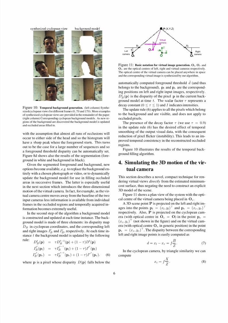
synthesized cyclopean view background model
Figure 10: Temporal background generation. (left column) Synthe-
sizedcyclopean views for different frames (0, 70 and 170). More examples
of synthesised cyclopean views are provided in the remainder of the paper.
(right column) Corresponding cyclopean background models. As new re-
gions of the background are discovered the background model is updated
and occluded areas filled in.
with the assumption that almost all runs of occlusions will
occur to either side of the head and so the histogram will
have a sharp peak where the foreground starts. This turns
out to be the case for a large number of sequences and so
a foreground threshold disparity can be automatically set.
Figure 8d shows also the results of the segmentation (fore-
ground in white and background in black).
Given the segmented foreground and background, new
options become available, e.g. to replace the background en-tirely with a chosen photograph or video, or to dynamically
update the background model for use in filling occluded
areas in successive frames. The latter is especially useful
in the next section which introduces the three-dimensional
motion of the virtual camera. In fact, for example, as the vir-
tual camera centre moves away from the baseline of the two
input cameras less information is available from individual
frames in the occluded regions and temporally acquired in-
formation becomes extremely useful.
In the second step of the algorithm a background model
is constructed and updated at each time instance. The back-
ground model is made of three elements: its disparity map
DB in cyclopean coordinates, and the corresponding leftand right images I lB and I rB , respectively. At each time in-
stance t the background model is updated by the following
rule:DtB(p) = τ Dt−1
B (p) + (1− τ )Dt(p)
I lt
B(pl) = τ I lt−1
B (pl) + (1− τ )I lt
(pl)
I rt
B (pr) = τ I rt−1
B (pr) + (1− τ )I rt
(pr). (6)
where p is a pixel whose disparity D(p) falls below the
P(X,Y,Z)
f
xlxv
xr
Ol
Ov
Or
X
Z
Y
O
Left
cameraRight
camera
Virtual
camera
Figure 11: Basic notation for virtual image generation. Ol, Or and
Ov are the optical centres of left, right and virtual cameras respectively.
The optical centre of the virtual camera can be placed anywhere in space
and the corresponding virtual image is synthesized by our algorithm.
automatically computed foreground threshold d̂ (and thus
belongs to the background), pl and pr are the correspond-
ing positions on left and right input images, respectively.
DtB(p) is the disparity of the pixel p in the current back-
ground model at time t. The scalar factor τ represents a
decay constant (0 ≤ τ ≤ 1) and I indicates intensities.
The update rule (6) applies to all the pixels which belong
to the background and are visible, and does not apply tooccluded pixels.
The presence of the decay factor τ (we use τ = 0.9)
in the update rule (6) has the desired effect of temporal
smoothing of the output visual data, with the consequent
reduction of pixel flicker (instability). This leads to an im-
proved temporal consistency in the reconstructed occluded
regions.
Figure 10 illustrates the results of the temporal back-
ground filling algorithm.
4. Simulating the 3D motion of the vir-
tual cameraThis section describes a novel, compact technique for ren-
dering virtual views directly from the estimated minimum-
cost surface, thus negating the need to construct an explicit
3D model of the scene.
Figure 11 shows a plan view of the system with the opti-
cal centre of the virtual camera being placed in Ov.
A 3D scene point P is projected on the left and right im-
ages into the points pl = (xl, yl) and pr = (xr, yr)
respectively. Also, P is projected on the cyclopean cam-
era (with optical centre in Oc = O) in the point pc =(xc, yc) (not shown in the figure) and on the virtual cam-
era (with optical centre Ov in generic position) in the pointpv = (xv, yv). The disparity between the corresponding
left and right image points is easily computed as
d = xl − xr = f B
Z . (7)
In the cyclopean camera, by triangle similarity we can
compute
xc = f X
Z . (8)
6

8/3/2019 Gaze Ma Nip La Ti On
http://slidepdf.com/reader/full/gaze-ma-nip-la-ti-on 7/8
Left image
R ig h t im
a g e Vi r t u
a l i m a g e
Q
D i sp a r
i t y
su r f a
ce
Left image
R i g h t i m
a g e
Q
8
+
8-
D i s p a r
i t y
s u rfa
c e
Vi r t u a l i m
a g e
a b
Inwards virtualcamera motion,
Outwards, Upwards, Downwards, R igh t, Left.
Figure 12: Virtual camera motion. (a) The 3D motion of the virtual
camera is achieved by direct projection of points on the minimum-cost
surface into the virtual image plane. (b) Moving the centre of projectionQ
corresponds to translating the virtual camera. The coloured arrows indicate
the mapping between moving the centre of projection Q in our diagram
and the corresponding translations of the virtual camera in the scene.
For a virtual camera with optical center in Ov =(T x, T y, T z) we can write: (X −T x) : xv = (Z −T z) : f ,
from whichxv = f
X − T xZ − T z
. (9)
By substituting (7) and (8) into (9) we obtain:
xv = f xc−dT x/B1−dT z/(fB) which, together with the analogous
equation for the yv coordinate, can be rewritten in homoge-
neous coordinates as:
xv
yvw
=
1 0 −T x/B 0
0 1 −T y/B 00 0 −T z/(fB) 1
xcycd1
. (10)
Equation (10) represents a projection of 3D points into a
plane. It can be proven that (10) corresponds to projectingpoints of the disparity surface into the corresponding points
on the plane of the virtual image (up to a scale, diagonal
matrix) as illustrated in fig. 12a.
From (10) the centre of projectionQ is readily computed
as the null vector of the projection matrix, thus yielding:
Q =
T xB
T yB 1 T z
fB
.
Notice that for T z = 0 the transformation (10) is a par-
allel projection (Q is at infinity). This, in turn means that
sidewise (in the X direction) and up/down (in the Y di-
rection) motion of the virtual camera can be simulated by
simple projection of points of the min-cost surface onto the
virtual image plane via parallel rays.The inwards/outwards translation of the virtual camera
(T z = 0), instead, is achieved by means of a central projec-
tion with finite centre of projection Q.
The simple mapping between the motion of the centre of
projection Q and the corresponding translation of the vir-
tual camera is illustrated in 12b. For instance, inwards cam-
era translation (not zoom) is achieved by moving the centre
Q from +∞ towards the plane of the virtual image.
a b c
Figure 13: Example of gaze correction. (a,c) Input left and right views,
respectively; (b) Our algorithm does correct the gaze while eliminating the
artefacts. To be compared with fig. 2.
BackwardForward
Input left view Input right view
Figure 14: Forward/backward translation of virtual camera. The
bottom row shows the synthesized cyclopean views with (left) forward vir-
tual camera translation, (center) cyclopean view, (right) backward virtual
camera translation. Notice the parallax effect around the head.
Notice that for Q = (−1/2, 0, 1, 0) (i.e. Ov =(−B/2, 0, 0)) the virtual image corresponds to the in-
put left image, for Q = (1/2, 0, 1, 0) (i.e. Ov =(B/2, 0, 0)) the virtual image corresponds to the in-
put right image, and for Q = (0, 0, 1, 0) (i.e. Ov =(0, 0, 0)) the virtual image corresponds to the half-way cy-
clopean image.
In order to produce high quality output images inverse
mapping and bilinear interpolation techniques are used.
5. Results
Generating cyclopean views from still image pairs.
Figure 13 shows an example where the input left and right
images of fig. 2 have been used to generate the cyclopean
view via our algorithm. Notice that the spatial artefacts
(streaks in fig. 2b) have been considerably reduced. In the
central image the gaze has been corrected.
3D translation of the virtual camera. Figure 14 shows
an example of translating the virtual camera towards and
away from the viewed scene. This is different from sim-
ple zooming or cropping of the output image. In fact, par-
allax effect may be noticed in the boundary between the
head and the background, thus providing the correct three-
dimensional feeling.
7

8/3/2019 Gaze Ma Nip La Ti On
http://slidepdf.com/reader/full/gaze-ma-nip-la-ti-on 8/8
RightLeft
U p
D o w n
Figure 15: In-plane translation of virtual camera. The left and right
input images are the same as in fig. 14. This table shows the synthesized
images corresponding to translation of the virtual camera along the x and
y axes. Notice the parallax effect around the head. Also, the door frame isreconstructed nicely despite its partial occlusion in the right input view.
Figure 15 shows an example of in-plane translation
(along the X and Y directions) of the virtual camera. No-
tice the relative displacement of the head with respect to the
background.
Cyclopean view generation in long sequences. Finally
fig. 16 demonstrates the effectiveness of the proposed algo-
rithm for reconstructing cyclopean views of extended tem-
poral sequences. Notice that most of the spatial and tempo-
ral artefacts are removed.
6. Conclusions and Future Work
We have presented an efficient algorithm for the synthesis
and geometric manipulation of high-quality virtual images
from a pair of synchronized stereo sequences with large
disparities (0 − 80 pixels). In this paper we have focused
on one-to-one teleconferencing applications but the tech-
niques described are more general and can be employed
in other applications requiring novel view generation and
dense stereo.
The newly proposed three-layer graph for dynamic pro-
gramming, the anisotropic cost filtering and the temporal
background model building have been demonstrated effec-tive in the synthesis of novel views with a virtual camera
placed in a generic location.
With the current unoptimized implementation these re-
sults have been produced at a rate of about a frame every 2sec (on 320× 240 images, on a 2.8Ghz Pentium).
Finally, for the future development of the work presented
in this paper, thorough experimentation with different cam-
era layouts, code optimization for real-time synthesis, and
Figure 16: Gaze correction for long sequences. Frames extracted from
a reconstructed cyclopean sequence (over 10 sec long).
the generation of standard test sequences for evaluation of the algorithm will be necessary.
Acknowledgements. The authors would like to thank
C.Rother, I.Cox, P.Anandan and R.Szeliski for their useful
comments and inspiring discussions.
References
[1] E. Chen and L. Williams. View interpolation for image synthesis. In
SIGGRAPH , pages 279–288, 1993.
[2] I. Cox, M. Ott, and J.P. Lewis. Videoconference system using a vir-
tual camera image. US Patent , 5,359,362, 1993.
[3] I.J. Cox, S.L. Hingorani, and S.B. Rao. A maximum likelihood stereo
algorithm. Computer vision and image understanding, 63(3):542–567, 1996.
[4] J. Gemmell, K. Toyama, C. Zitnick, T. Kang, and S. Seitz. Gaze
awareness for video-conferencing: A software approach. IEEE Mul-
timedia, 7(4), 2000.
[5] V. Kolmogorov and R. Zabih. Multi-camera scene reconstruction via
graph cuts. In Proc. Europ. Conf. Computer Vision, Copenhagen,
Denmark, May 2002.
[6] Y. Ohta and T. Kanade. Stereo by intra- and inter-scan line search
using dynamic programming. IEEE Trans. on Pattern Analysis and
Machine Intelligence , 7(2):139–154, 1985.
[7] S. Roy and I.J. Cox. A maximum-flow formulation of the n-camera
stereo correspondence problem. In Proc. Int. Conf. Computer Vision,
pages 492–499, 1998.
[8] D. Scharstein and R. Szeliski. A taxonomy and evaluation of dense
two-frame stereo correspondence algorithms. Int. J. Computer Vi-sion, 47(1–3):7–42, 2002.
[9] J. Sun, H. Y. Shum, and N. N. Zheng. Stereo matching using belief
propagation. In Proc. Europ. Conf. Computer Vision, Copenhagen,
Denmark, May 2002.
[10] T. Vetter. Synthesis of novel views from a single face image. Int. J.
Computer Vision, 28(2):103–116, 1998.
[11] R. Yang and Z. Zhang. Eye gaze correction with stereovision for
video tele-conferencing. In Proc. Europ. Conf. Computer Vision, vol-
ume 2, pages 479–494, Copenhagen, Denmark, May 2002.
8