Gauges, Test Equipment and Tank Accessories Gauge and Test Catalog R0117 WEB.pdf · Gauges, Test...
20
www.anfieldindustries.com Gauges, Test Equipment and Tank Accessories
Transcript of Gauges, Test Equipment and Tank Accessories Gauge and Test Catalog R0117 WEB.pdf · Gauges, Test...

www.anfieldindustries.com
Gauges, Test Equipmentand Tank Accessories

TABLE OF CONTENTS
Gauges, Test Equipment and Tank Accessories
MPD DRY GAUGES 3 MPG LIQUID- FILLED GAUGES 4 EUROPEAN
INTERCHANGEABLE TEST POINT PLUGS
6
37º J.I.C. HYDRAULIC HOSE COUPLING WITH TEST POINT PLUG
7 DIRECT GAUGEADAPTER PROBE 8 HOSE/PROBE
ASSEMBLIES 9
GAUGE TO HOSEADAPTERS 10 FLUID
SAMPLING KIT 11 DRIVE COUPLINGS 12
LEVEL GAUGE 15 TANK MOUNTED STRAINER 16 SUCTION STRAINER 17
METAL FILLERBREATHER 18

3
C
E
G
D
TW
Dry gauges
SPECIFICATIONSn All gauges are a one piece design. Socket Copper alloyCase Black steelBourdon Tube Circular in copper alloy up to 600 PSI Helical above 900 PSIMovement Copper alloyWindow AcrylicDial White plastic, black scalePointer Black ABS plasticConnection Bottom (Model A); Center back (Model D)Standard Threads 1/4" NPT, 1/8" NPT on some sizesAccuracy Class 1.6 - 2.5 ANSI B40.1 Grade BTemperature Range Ambient: -40ºC to 60ºC, Media: max 60ºCPressure Utilization Static 75% max. scale; Dynamic 66% max. scaleProtection Degree IP 43Scale Concentric 270º PSI/BarCustom gauges available, please contact Anfield.
DIMENSIONS
Additional options are available. Please contact Anfield Industries for details.
MODEL MPD
ORDERING INFORMATION
Dry gaugemodel
MPDDiameter1 - 2-1/2"3 - 2"4 - 1-1/2"
1TypeP - Pressure
P 30Thread1/4" - 1/4" NPT1/8"* - 1/8" NPT* Available for 1-1/2" and 2" back mount gauges only
1/4" Pressure range (PSI)
3 denotes availability by size PSI 1-1/2" 2" 2-1/2" 30 3 3 3 60 3 3 3 100 3 3 3 160 3 3 3 200 3 3 300 3 600 3 1000 3 2000 3 3000 3 4000 3 5000 3
ConnectionA - BottomD - Center back
A
n "A" nominal size A
B
BottomMount
CenterBack

4 Liquid-filled gauges
MODEL MPG
ORDERING INFORMATION
Liquid-filledgauge model
MPGDiameter1 - 2-1/2"2 - 4"
1TypeV - VacuumC - CompoundP - Pressure
V 30ThreadN - 1/4" NPTS - SAE-4
NPressure range 30/0 - 30 in.Hg/0 psi30/30 - 30 in.Hg/30 psi30 - 30 psi60 - 60 psi100 - 100 psi160 - 160 psi200 - 200 psi300 - 300 psi600 - 600 psi1000 - 1000 psi1500 - 1500 psi2000 - 2000 psi3000 - 3000 psi4000 - 4000 psi5000 - 5000 psi6000 - 6000 psi10000 - 10000 psi
StyleA - Bottom stemB - Panel clamp**D - Center back (Not available on 4" gauge)
E - Panel flange** (Not available on 4" gauge)
* Panel flange and clamp may be ordered separately to fit "D" style gauge 2-1/2" model only.Part Number:MPG-1-E - FlangeMPG-1-B - Clamp
A
Our MPG series is a high quality line of glycerin filled 2 ½” and 4” pressure gauges typically used in hydraulic and pneumatic systems where vibration and pulsation are present. The glycerin is used to keep the internal parts lubricated, keeps contamination away from the moving parts and helps reduce vibration and shock. Available in vacuum through 10,000psi.
SPECIFICATIONSn All gauges are a one piece design. Socket Copper alloyCase Stainless steelFlange and Ring Stainless steel (Model E)Ring Stainless steel (Model B)Bourdon Tube Circular in copper alloy up to
600 PSI, Helical in copper alloy above 900 PSI
Movement Copper alloyWindow Polycarbonate, acrylic 4"Dial White ABS, black scalePointer Black enamelled aluminiumMounting Model E: Front flange with
3 mounting holes Model B: With special ring and back clamp.
Connection Bottom (Model A) Center back (Model D) 2 1/2". Lower back 4"Standard Threads 1/4 NPT and SAE -4Filling Liquid Glycerine fluidAccuracy 1.5% of spanTemperature Range Between -20ºC to + 80ºCWorking Range Steady: 3/4 scale valve, Fluctuating: 2/3 scale valve, Short time: full scaleProtection Degree IP 65Scale Concentric 270º - PSI/Bar
Custom gauges available, please contact Anfield.
DESCRIPTION

55
DIMENSIONS
Additional options are available. Please contact Anfield Industries for details.
Liquid-filled gauges
2-1/2" MPG Model A 2-1/2" MPG Model D & E
2-1/2" MPG Model B
n "A" nominal sizen T = 7/16" - 20" SAE Connection, Supplied with Viton o-ring, hex nut, and washer
4" MPG Model A

6
DESCRIPTION
These Test Point Plugs are designed to be complementary to and interchangeable with similar equipment from other manufacturers using DIN 2353 standards. Plugs are installed into the hydraulic system hardware and are used in conjunction with DIN 2353 Pressure Test Probe equipment. The equipment is used to obtain random pressure checks during servicing and fault finding. Probes may be connected and disconnected at full system pressure without fluid loss or ingress of dirt.
TECHNICAL DATA
EUROPEANINTERCHANGEABLETEST POINT PLUGS
n Conforms to DIN 2353 standard
n Working pressure up to 6000 PSI
n UNF, NPTF (standard), BSPP, BSPT & METRIC (special order) ranges available for connecting to system.
n Manufactured in steel and passivated
n Viton seals are standard -20ºC to +200ºC
n Symbol:
DIMENSIONS
UNF Series
A
B D A/F
ThreadM16 x 2.00
O Ringseal
A
B D A/F
ThreadM16 x 2.00
BSPT & NPTF Series BSPP Series
A
B D A/F
ThreadM16 x 2.00
C

7
DESCRIPTION
Install J.I.C. Hose Couplings between the female swivel nut of the flexible hose and the fixed male connection. The integral Test Point may then be used with Test Probes or test kits to obtain pressure or temperature checks during servicing or fault finding. The Fluid Sampling Probe is also compatible. All probes may be connected and disconnected at full system pressure without fluid loss or ingress of dirt.
TECHNICAL DATA
37º J.I.C. HYDRAULIC HOSE COUPLING WITH
TEST POINT PLUG
n Working pressure up to 6000 PSIn Fitted with test point plug (European interchangeable)n Can be used with direct or remote (flexible) test probesn For J.I.C. 37º sizes: 1/4" to 1-1/2"n Viton seals are standard -20ºC to +200ºC
DIMENSIONS
n Symbol:
CD
A
A B
E
FU.N.F. female
U.N.F. male
37°37°
Hex. A/Fswivel nut
Hex. A/F
Male thread for Test ProbeM16 x 2.00
0.91 in

8
DESCRIPTION
This Direct Gauge Adaptor Probe is designed for use with Test Point Plugs or with plugs of other manufacturers to DIN 2353 standard. It may be supplied with or without a rubber shrouded pressure gauge. The probe can be attached to any one of a number of plugs installed throughout the hydraulic system to facilitate random pressure readings during servicing and fault finding. Probes may be connected or disconnected at full system pressure without loss of oil or ingress of dirt.
DIRECT GAUGEADAPTOR
PROBE
TECHNICAL DATA
n Conforms to DIN 2353 standard n Working pressure up to 6000 PSIn For use with MPG series 2-1/2" & 4" diameter glycerine filled pressure gaugesn Suitable for HSP2000 & HSP1040 series test point plugs
DIMENSIONS
n Symbol:B
E
D
A
C
M16 x 2.00Thread
F
Protectivecap
0.91in
Hex.A/F
PROBES
n Gauges sold separately refer to Anfield’s MPG series Liquid Filled Gauges.

9
DESCRIPTION
These Hose/Probe assemblies are designed to be complementary to and interchangeable with similar equipment from other manufacturers using DIN 2353 standards. The Hose/Probe forms the link between the DIN 2353 hydraulic system Test Point Plugs and the Pressure Gauge/Adaptor assemblies, the whole arrangement being used to obtain random pressure checks during servicing and fault finding. Probes may be connected and disconnected at full system pressure without fluid loss or ingress of dirt.
HOSE/PROBEASSEMBLIES
TECHNICAL DATA
n Conforms to DIN 2353 standardn Working pressure at 50ºC up to 6000 PSIn Choice of flexible hose lengthsn Steel components passivated
DIMENSIONS
M16 x 2.00
M16 x 2.00
0.20 in.dia.
L
M16 x 2.00
M16 x 2.00
0.75 in. A/F
1.73 in.
Hose couplingassembly without
check valveHSP6100
(Permits hosesto be joined
together)
n Symbol:
OPTIONAL HOSE LENGTHS
* Working at 120ºC only allowed for a short time.
n Note: working pressure of hose must be de-rated as temperature increases. See table above.

10
DESCRIPTION
These adaptors are designed to be complementary to and interchangeable with similar equipment from other manufacturers using DIN 2353 standards. They are used to connect the gauge to Hose/Probe assemblies. Adaptors may be bulkhead mounted in a control console or test panel, or hand held for use in servicing and fault finding to obtain pressure checks when required. Test Point Plugs installed in the hydraulic system allow connection and disconnection at full system pressure without loss of oil or ingress of dirt.
TECHNICAL DATA
GAUGE TO HOSEADAPTORS
n Conforms to DIN 2353 standard n Working pressure up to 6000 PSIn To suit 1/4" or 1/2" NPTF or SAE gaugesn For use with MPG series pressure gauge
DIMENSIONS
E
A/F
B
C
AD
0.47 in.
Maximumpanelthickness
4 in.gauge5.22 in.
2-1/2 in.gauge3.41 in.
WEIGHTSn Adaptor with 2-1/2" gauge: 10.23 oz.n Adaptor with 4" gauge: 27.87 oz.

11
DESCRIPTION
The equipment comprises a screw on probe connected by flexible hose to an adjustable flow control valve which allows steady state fluid samples to be extracted from the working system ready for analysis. When used in conjunction with Test Point Plugs, the equipment facilitates the removal of fluid samples from selected points throughout a system without danger of extraneous contamination, even with the system at full working pressure and temperature.
TECHNICAL DATA
FLUIDSAMPLING KIT
n Designed for off-line bottle samplingn Adjustable flow control for steady state samplesn Operates up to 6000 PSI system pressuren Viton seals are standard -20ºC to +200ºC
DIMENSIONS
0.63 in. A/F
2.52
in.
2.17 in.
0.63 in. A/F
Metering valve
1.18in.
1.18in.
2.36 in.
4.45 in.
Thread compatiblewith Anfield Test Points
Dust cap
Female thread forAnfield Test Points
M16 x 2.00
1.85 in.
n Symbol:
12
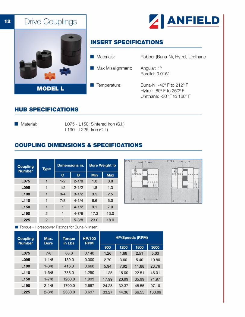
INSERT SPECIFICATIONS
n Materials: Rubber (Buna-N), Hytrel, Urethane
n Max Misalignment: Angular: 1º Parallel: 0.015” n Temperature: Buna-N: -40º F to 212º F Hytrel: -60º F to 250º F Urethane: -30º F to 160º F
HUB SPECIFICATIONS
n Material: L075 - L150: Sintered Iron (S.I.) L190 - L225: Iron (C.I.)
COUPLING DIMENSIONS & SPECIFICATIONS
� Torque - Horsepower Ratings for Buna-N Insert:
Bore Weight lb
Min Max
1.0
1.8
3.5
6.6
9.1
17.3
23.0
0.8
1.3
2.5
5.0
7.0
13.0
18.0
Dimensions in.
C B
1/2
1/2
3/4
7/8
1
1
1
2-1/8
2-1/2
3-1/2
4-1/4
4-1/2
4-7/8
5-3/8
CouplingNumber
L075
L095
L100
L110
L150
L190
L225
1
1
1
1
1
2
2
Type
CouplingNumber
Max.Bore
L075
L095
L100
L110
L150
L190
L225
7/8
1-1/8
1-3/8
1-5/8
1-7/8
2-1/8
2-3/8
Torquein Lbs
88.0
189.0
416.0
788.0
1260.0
1700.0
2330.0
HP/100RPM
0.140
0.300
0.660
1.250
1.999
2.697
3.697
HP/Speeds (RPM)
900 1200
1.26
2.70
5.94
11.25
17.99
24.28
33.27
1.68
3.60
7.92
15.00
23.99
32.37
44.36
1800 3600
2.51
5.40
11.88
22.51
35.99
48.55
66.55
5.03
10.80
23.76
45.01
71.97
97.10
133.09
Drive Couplings
MODEL L

13
STOCK BORE SIZES
REPLACEMENT INSERTS
SeriesNitriteInserts
L075
L095
L100
L110
L150
L190
L225
N-075
N-095
N-100
N-110
N-150
N-190
N-225
HytrelInserts
H-075
H-095
H-100
H-110
H-150
H-190
H-225
UrethaneInserts
U-075
U-095
U-100
U-110
U-150
U-190
U-225
n Raised dots on each side of the cushion insert provide the correct pre-measured gap between the jaw and spider.
N-075
L075 L095 L100 L110 L150 L190 L225Bore Key
1/8" x 1/16"
3/32" x 3/64"
1/8" x 1/16"
1/8" x 1/16"
1/8" x 1/16"
5/32" x 5/64"
3/16" x 3/32"
3/16" x 3/32"
3/16" x 3/32"
1/4" x 1/8"
1/4" x 1/8"
1/4" x 1/8"
1/4" x 1/8"
5/16" x 5/32"
5/16" x 5/32"
3/8" x 3/16"
3/8" x 3/16"
3/8" x 3/16"
1/2" x 1/4"
1/2" x 1/4"
1/2" x 1/4"
1/2" x 1/4"
5/8" x 5/16"
3/8
7/16
7/16
1/2
9/16
5/8
5/8
3/4
7/8
7/8
1
1-1/8
1-1/4
1-1/4
1-3/8
1-1/2
1-5/8
1-3/4
1-7/8
2
2-1/8
2-1/4
2-3/8
9Q00500
9Q00550
9Q00900
9Q00600
9Q00700
9Q00800
9Q01200
9Q01300
9Q01350
9Q01900
9Q01400
9Q01500
9Q01600
9Q02000
9Q01700
9Q01800
9Q02200
9Q02300
9Q02350
9Q03100
9Q02400
9Q02500
9Q02600
9Q03200
9Q02700
9Q02800
9Q02900
9Q03250
9Q03000
9Q04300
9Q03400
9Q03500
9Q03600
9Q04400
9Q03700
9Q03800
9Q03900
9Q04450
9Q04000
9Q04100
9Q04200
9Q04590
9Q04600
9Q04700
9Q04800
9Q05700
9Q04900
9Q05000
9Q05100
9Q05750
9Q05200
9Q05300
9Q05400
9Q05500
9Q05600
9Q05761
9Q05765
9Q05763
9Q05764
9Q05772
9Q05766
9Q05767
9Q05769
9Q05768
9Q05770
9Q05780
9Q05785
9Q05790
9Q05795
9Q06000
9Q06050
9Q06100
9Q06200
9Q06300
9Q07400
9Q07450
9Q06500
9Q06600
9Q06650
9Q06800
9Q06900
9Q07000
9Q07100
9Q07200
Drive Couplings

14
HUB DIMENSIONS AND SPECIFICATIONS
Bore Tolerances
Up to 1-7/16
Over 1-1/2
+.0015/-.000
+.002/-.000
ORDERING INFORMATION
L100 1-1/8" x 1/4"
Electric Motor HalfSeries
L075
L095
L100
L110
L150
L190
L225
Prime Mover, Shaft Bore/Key
5/8 x 5/32
Pump Half
Pump Shaft, Bore/Key
BORE TOLERANCE
n Order by code from chart below or by Anfield part number from chart on page 2.
Drive Couplings
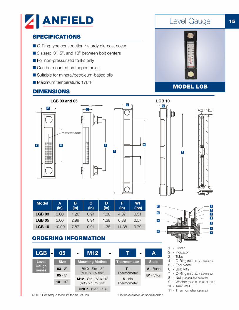
15Level Gauge
SPECIFICATIONS
n O-Ring type construction / sturdy die-cast cover
n 3 sizes: 3”, 5”, and 10” between bolt centers
n For non-pressurized tanks only
n Can be mounted on tapped holes
n Suitable for mineral/petroleum-based oils
n Maximum temperature: 176°F
DIMENSIONSMODEL LGB
ORDERING INFORMATION
LGB 05 TSize
03 - 3”
05 - 5”
10 - 10”
Model A(in)
B(in)
C(in)
D(in)
F(in)
Wt (lbs)
LGB 03 3.00 1.26 0.91 1.38 4.37 0.51
LGB 05 5.00 2.99 0.91 1.38 6.38 0.57
LGB 10 10.00 7.87 0.91 1.38 11.38 0.79
Level Gaugeseries
-Thermometer
T - Thermometer
S - No Thermometer
- M12Mounting Method
M10 - Std - 3” (M10 x 1.5 bolt)
M12 - Std - 5” & 10” (M12 x 1.75 bolt)
UNC* - (1/2” - 13)
-
D
F B A
FRONT VIEW SIDE VIEW
THERMOMETER
C
2.09"
F
B
D C
A
LGB 03 and 05 LGB 10
1
2
3
4
5
6
78
9
10
11
1 - Cover2 - Indicator3 - Tube4 - O-Ring (13.0 I.D. x 2.6 c.s.d.)
5 - End piece6 - Bolt M127 - O-Ring (13.0 I.D. x 3.0 c.s.d.)
8 - Nut (Flanged and serrated)
9 - Washer (27 O.D. 13.0 I.D. x 3 t)
10 - Tank Wall11 - Thermometer (optional)
NOTE: Bolt torque to be limited to 3 ft. lbs.
ASeals
A - Buna
B* - Viton
-
*Option available via special order

16 Tank Mounted Strainer
SPECIFICATIONS
n No by-pass
n Perforated steel support tubes
n Temperatures to +250ºF (+120ºC)
n 100 Mesh stainless steel plated elements
n 5 PSI by-pass (optional)
n Designed for ease of servicing Access to tank interior is not necessary
n Mount through sidewall or through tank top and into a standpipe
TMS SERIES
ORDERING INFORMATION
Model GPM Rating
A B C(in)
D(in)
E (in)
Screen Area(in2)
TMS-3 3 3/4" NPT 3/8" NPT 4.00 0.97 0.87 28.70
TMS-5 5 1" NPT 1/2" NPT 5.34 1.06 1.03 35.00
TMS-10 10 1-1/4" NPT 3/4" NPT 8.17 1.10 1.36 64.00
TMS-15 15 1-1/2" NPT 1" NPT 8.20 1.30 1.62 86.00
TMS-25 25 2" NPT 1-1/4" NPT 9.04 1.30 2.12 125.00
TMS-50 50 3" NPT 2" NPT 9.70 1.70 3.00 260.00
TMS-100 100 4" NPT 3" NPT 11.30 1.80 4.00 315.00

17Suction Strainer
SPECIFICATIONS
n Reusable stainless steel 100 mesh, 149 micron standard
n Nylon nut
n Steel cap / support tube
n Maximum working temperature: 176°F
n Suitable for hydraulic/mineral oils
n Consult factory for water application
n Flexible magnetic wrap available
DIMENSIONS
MODEL SE
ORDERING INFORMATION
SE 005 N
Model Flow(gpm)
A Thread NPT (in)
BOverall
Length (in)
CDia. Nut Cap (in)
A/FNut(in)
Screen Area(in2)
Wt (lbs)
Magnet Wrap
SE-005 5.28 1/2 3.11 2.68 0.98 62.00 0.44 1
SE-007 7.93 3/4 3.58 2.68 1.42 67.89 0.44 2
SE-010 10.57 1 5.39 2.68 1.61 110.05 0.66 2
SE-020 21.13 1-1/4 6.89 3.35 1.97 161.98 0.99 2
SE-030 31.70 1-1/2 8.11 3.35 2.32 224.91 1.21 2
SE-050 52.83 1-1/2 10.00 4.02 2.76 339.92 1.43 2
SE-051 52.83 2 10.00 4.02 2.76 339.92 1.76 3
SE-075 79.25 2-1/2 10.20 5.16 3.35 399.90 2.31 3
SE-100 105.70 3 11.81 5.16 3.78 499.88 3.00 3
SuctionStrainerseries
-Port Threads Connection
N - NPT (Std)
Consult factory for optional/special features.
149Microns
149 - SS100 Mesh
Size
- - **Bypass
RB3 - 3 PSI Bypass(Optional)
- **Magnet Wrap
M - Magnet Wrap
(Optional)
-
C
AB
A/F

18 Metal Filler Breather
SPECIFICATIONS
n Chrome-plated steel cap - vents underneath.
n Filtration 40 microns standard, 10 microns optional.
n Air Flows To 25 CPM (750 LPM)
n Metal Strainer Standard
n Hardware includes gaskets and 10-32 screws.
DIMENSIONS
MODEL FBA
ORDERING INFORMATION
FBA 80 B40 A0 01-Filtration(microns)
B40 - 40 µ std
B10 - 10 µ nominal
FLANGE TYPEA
B
C
D
3.28"
6 HOLES P.C.D.2.81"
OPTIONAL FEATURESA
B
C
D
LOCKING TAB
HOLE
6 HOLES ON 2.81"P.C.D.
10 MICRONELEMENT
Model Displacement (GPM)
Rating (microns)
A(in)
B(in)
C(in)
D(in)
Wt (lbs)
FBA-80 B40 190.20 40 3.03 2.44 3.58 1.97 0.55
FBA-80 B10 105.67 10 3.03 2.44 3.58 1.97 0.55
Metal FillerBreather
series
--Strainer
A0 - 3.58”
A002 - 6”
A003 - 8”
DS4Dipstick Option
Blank - No Dipstick
DS4 - 4”
DS6 - 6”
DS8 - 8”
- -Locking
Tab
01 - Without tab
L1 - With tab


www.anfieldindustries.com
USAAnfield Industries Inc.375 International Park, Suite 300 Newnan, Georgia 30265Phone: (404) 530-3804Fax: (404) 530-3805Email: [email protected]: www.anfieldindustries.com
CanadaMP Filtri Canada, Inc.8831 Keele StreetConcord, Ontario, Canada, L4K 2N1Phone: (905) 303-1369Fax: (905) 303-7256Email: [email protected]: www.mpfiltricanada.com
Gauges and Test Equipment Catalog2017 R0117
Strength in Products, Strength in Service
n Pressure Switches
n Temperature Switches
n Transducers
n Gear Pumps
n Flow Dividers
n Hydraulic Motors
n Jaw Couplings
n High Pressure Ball Valves
n Flow Control and Needle Valves
n Test Points
n Gauges
n Monoblock Valves
n Sectional Valves