Gate ee 2012 with solutions
52
GATE EE 2012 Brought to you by: Nodia and Company Visit us at: www.nodia.co.in PUBLISHING FOR GATE Q. 1 - Q. 25 carry one mark each. MCQ 1.1 Two independent random variables X and Y are uniformly distributed in the interval , 11 − 6 @ . The probability that , max XY 6 @ is less than / 12 is (A) / 34 (B) / 9 16 (C) / 14 (D) / 23 SOL 1.1 Option (B) is correct. Probability density function of uniformly distributed variables X and Y is shown as [ ( , )] max P xy 2 1 < & 0 Since X and Y are independent. [ ( , )] max P xy 2 1 < & 0 PX PY 2 1 2 1 < < = b b l l PX 2 1 < b l shaded area 4 3 = = Similarly for Y : PY 2 1 < b l 4 3 = So [ ( , )] max P xy 2 1 < & 0 4 3 4 3 16 9 # = = Alternate method:
-
Upload
khemraj298 -
Category
Engineering
-
view
154 -
download
7
Transcript of Gate ee 2012 with solutions
GATE EE2012
Brought to you by: Nodia and Company Visit us at: www.nodia.co.in
PUBLISHING FOR GATE
Q. 1 - Q. 25 carry one mark each.
MCQ 1.1 Two independent random variables X and Y are uniformly distributed in the interval ,1 1−6 @. The probability that ,max X Y6 @ is less than /1 2 is(A) /3 4 (B) /9 16
(C) /1 4 (D) /2 3
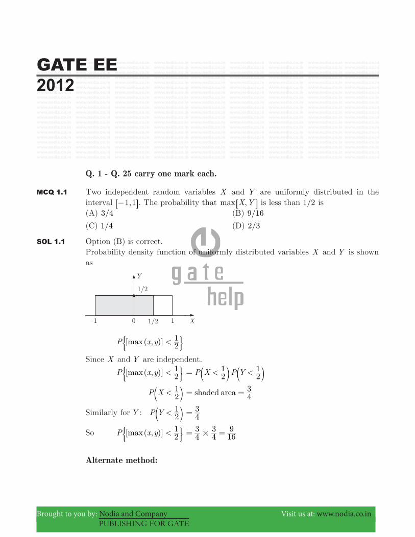
SOL 1.1 Option (B) is correct.Probability density function of uniformly distributed variables X and Y is shown as
[ ( , )]maxP x y 21<& 0
Since X and Y are independent.
[ ( , )]maxP x y 21<& 0 P X P Y2
121< <= b bl l
P X 21<b l shaded area 4
3= =
Similarly for Y : P Y 21<b l 4
3=
So [ ( , )]maxP x y 21<& 0 4
343
169
#= =
Alternate method:

Page 2 GATE EE 2012 www.gatehelp.com
Brought to you by: Nodia and Company Visit us at: www.nodia.co.in
PUBLISHING FOR GATE
From the given data since random variables X and Y lies in the interval [ , ]1 1− as from the figure X , Y lies in the region of the square ABCD .Probability for , 1/2max X Y <6 @ : The points for , /max X Y 1 2<6 @ will be inside the region of square AEFG .
So, ,maxP X Y 21<6 @& 0 Area of square
Area ofABCD
AEFG4=
2 223
23
169
#
#= =
MCQ 1.2 If ,x 1= − then the value of xx is(A) e /2π− (B) e /2π
(C) x (D) 1
SOL 1.2 Option (A) is correct.
x i1= − = cos sini2 2π π= +
So, x ei 2=π
xx ei x2=π
^ h & ei i2π
^ h
e 2=π−
MCQ 1.3 Given ( )f z z z11
32= + − + .
If C is a counter clockwise path in the z -plane such that z 1 1+ = , the value of
( )j f z dz21
Cπ # is
(A) 2− (B) 1−
(C) 1 (D) 2
SOL 1.3 Option (C) is correct.
( )f z z z11
32= + − +

Page 3 GATE EE 2012 www.gatehelp.com
Brought to you by: Nodia and Company Visit us at: www.nodia.co.in
PUBLISHING FOR GATE
( )j f z dz21
Cπ # = sum of the residues of the poles which lie inside the given closed region. C z 1 1& + =Only pole z 1=− inside the circle, so residue at z 1=− is.
( )f z ( )( )z z
z1 3
1= + +− +
( )( )
( )( )lim
z zz z
1 31 1
22 1
z 1= + +
+ − + = ="−
So ( )j f z dz21
Cπ # 1=
MCQ 1.4 In the circuit shown below, the current through the inductor is
(A) Aj12+ (B) Aj1
1+
−
(C) Aj11+ (D) 0 A
SOL 1.4 Option (C) is correct.

Page 4 GATE EE 2012 www.gatehelp.com
Brought to you by: Nodia and Company Visit us at: www.nodia.co.in
PUBLISHING FOR GATE
Applying nodal analysis at top node.
1 1j
V V1
01
01 1c c+ + + 1 0c=
( 1 1) 1 1j jV 01 c+ + + j1=
V1 j1 11= +
−
Current I1 1
j jjV
10
11
1 11 c= + =
− + +
( )
Aj j
jj1 1
1= + = +MCQ 1.5 The impedance looking into nodes 1 and 2 in the given circuit is
(A) 05 Ω (B) 100 Ω
(C) 5 kΩ (D) 10.1 kΩ
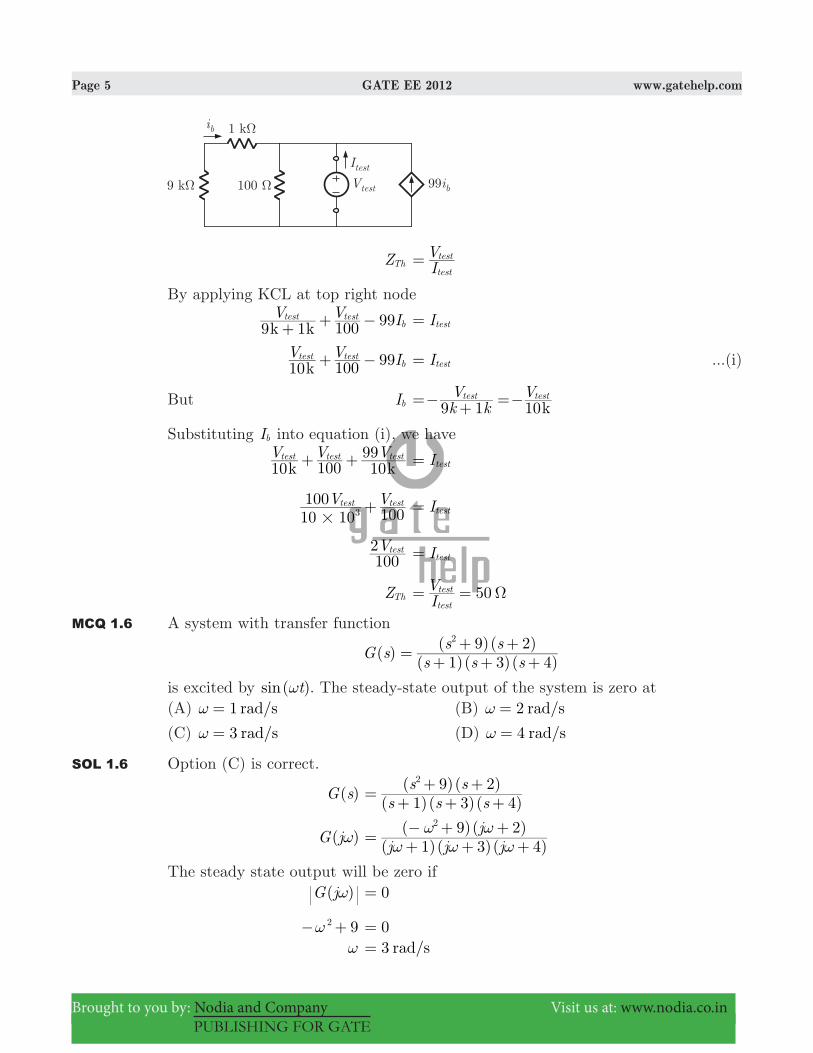
SOL 1.5 Option (A) is correct.We put a test source between terminal 1, 2 to obtain equivalent impedance
Page 5 GATE EE 2012 www.gatehelp.com
Brought to you by: Nodia and Company Visit us at: www.nodia.co.in
PUBLISHING FOR GATE
ZTh IV
test
test=
By applying KCL at top right node
9 1 99k kV V I100
test testb+ + − Itest=
99kV V I10 100
test testb+ − Itest= ...(i)
But Ib 10kk kV V
9 1test test=− + =−
Substituting Ib into equation (i), we have
10 10k kV V V
10099test test test+ + Itest=
V V10 10100
100test test
3#
+ Itest=
V1002 test Itest=
ZTh 50IV
test
test Ω= =
MCQ 1.6 A system with transfer function
( )( )( )( )
( )( )G s
s s ss s1 3 4
9 22
= + + ++ +
is excited by ( )sin tω . The steady-state output of the system is zero at(A) 1 /rad sω = (B) /rad s2ω =
(C) /rad s3ω = (D) /rad s4ω =
SOL 1.6 Option (C) is correct.
( )G s ( )( )( )
( )( )s s s
s s1 3 4
9 22
= + + ++ +
( )G jω ( )( )( )
( )( )j j j
j1 3 4
9 22
ω ω ωω ω= + + +
− + +
The steady state output will be zero if ( )G jω 0=
92ω− + 0= ω 3 /rad s=

Page 6 GATE EE 2012 www.gatehelp.com
Brought to you by: Nodia and Company Visit us at: www.nodia.co.in
PUBLISHING FOR GATE
MCQ 1.7 In the sum of products function ( , , ) ( , , , ),f X Y Z 2 3 4 5= / the prime implicants are(A) ,XY XY (B) , ,XY X Y Z XYZ
(C) , ,XYZ XYZ XY (D) , , ,XYZ XYZ XY Z XYZ
SOL 1.7 Option (A) is correct.Prime implicants are the terms that we get by solving K-map
F XY XYprime implicants
= +1 2 344 44
MCQ 1.8 If [ ] (1/3) (1/2) [ ],x n u nn n= − then the region of convergence (ROC) of its z-transform in the z -plane will be
(A) z31 3< < (B) z3
121< <
(C) z21 3< < (D) z3
1 <
SOL 1.8 Option (C) is correct.
[ ]x n [ ]u n31
21n n
= −b bl l
[ ]x n [ ] [ 1] ( )u n u n u n31
31
21n n n
= + − − −−
b b bl l l
Taking z -transform
X z6 @ [ ] [ ]z u n z u n31
31 1
nn
nn
nn
= + − −3
3
3
3− − −
=−=−b bl l//
[ ]z u n21 n
n
n
−3
3−
=−b l/
z z z31
31
21n
n
n
nn
n
nn
n0
1
0
= + −3
3
3−
=
− −
=−
−−
=b b bl l l/ / /
z z z31
31
21
I II III
n
n
m
m
n
n0 1 0
= + −3 3 3
= = =b b bl l l
1 2 344 44 1 2 344 44 1 2 344 44
/ / / Taking m n=−
Series I converges if z31 1< or z 3
1>
Series II converges if z31 1< or z 3<
Series III converges if z21 1< or z 2
1>
Page 7 GATE EE 2012 www.gatehelp.com
Brought to you by: Nodia and Company Visit us at: www.nodia.co.in
PUBLISHING FOR GATE
Region of convergence of ( )X z will be intersection of above three
So, ROC : z21 3< <
MCQ 1.9 The bus admittance matrix of a three-bus three-line system is
Y j13105
101810
51013
=−
−−
R
T
SSSS
V
X
WWWW
If each transmission line between the two buses is represented by an equivalent π-network, the magnitude of the shunt susceptance of the line connecting bus 1 and 2 is(A) 4 (B) 2
(C) 1 (D) 0
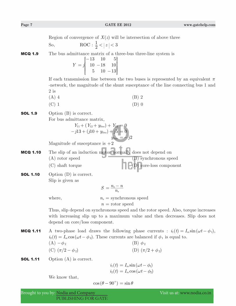
SOL 1.9 Option (B) is correct.For bus admittance matrix, ( )Y Y y Yline11 12 13+ + + 0= ( )j j y j13 10 5line− + + + 0= yline j2=−Magnitude of susceptance is 2+
MCQ 1.10 The slip of an induction motor normally does not depend on(A) rotor speed (B) synchronous speed
(C) shaft torque (D) core-loss component
SOL 1.10 Option (D) is correct.Slip is given as
S nn n
s
s= −
where, ns = synchronous speed n = rotor speedThus, slip depend on synchronous speed and the rotor speed. Also, torque increases with increasing slip up to a maximum value and then decreases. Slip does not depend on core/loss component.
MCQ 1.11 A two-phase load draws the following phase currents : ( ) ( ),sini t I tm1 1ω φ= − ( ) ( )cosi t I tm2 2ω φ= − . These currents are balanced if 1φ is equal to.
(A) 2φ− (B) 2φ
(C) ( / )2 2π φ− (D) ( / )2 2π φ+
SOL 1.11 Option (A) is correct. ( )i t1 ( )sinI tm 1ω φ= − ( )i t2 ( )cosI tm 2ω φ= −We know that, ( )cos 90cθ − sinθ=

Page 8 GATE EE 2012 www.gatehelp.com
Brought to you by: Nodia and Company Visit us at: www.nodia.co.in
PUBLISHING FOR GATE
So, ( )i t1 can be written as ( )i t1 ( )cosI t 90m 1 cω φ= − − ( )i t2 ( )cosI tm 2ω φ= −Now, in phasor form I1 I 90m 1 cφ= + I2 Im 2φ=Current are balanced if I I1 2+ 0= I I90m m1 2cφ φ+ + 0=
cos sin cos sinI jI j90 90m m1 1 2 2c cφ φ φ φ+ + + + +^ ^h h 0=
cos sin cos sinI j I j90 90 2 2m m1 1c cφ φ φ φ+ + + + +^ ^h h8 6B @ 0=
cos cos sin sinI jI90 90m m1 2 2 1c cφ φ φ φ+ + + + +^ ^h h8 8B B 0=
cos cos901 2cφ φ+ +^ h 0= cos 901 cφ +^ h cos cos2 2φ π φ=− = +^ h 901 cφ + 2π φ= +
or, 1φ 2 2π φ= +
MCQ 1.12 A periodic voltage waveform observed on an oscilloscope across a load is shown. A permanent magnet moving coil (PMMC) meter connected across the same load reads
(A) 4 V (B) 5 V
(C) 8 V (D) 10 V
SOL 1.12 Option (A) is correct.PMMC instrument reads average (dc) value.
Vavg ( )T v t dt1 T
0= #
( )v t dt20 10
13
0
20
#= − #

Page 9 GATE EE 2012 www.gatehelp.com
Brought to you by: Nodia and Company Visit us at: www.nodia.co.in
PUBLISHING FOR GATE
( )tdt dt dt201 5 5
0
10
10
12
12
20= + − +; E# # #
5 5t t t201
22
0
10
1012
1220= − +c m: 6 6D @ @
[50 5(2) 5(8)]201= − +
4 V2080= =
MCQ 1.13 The bridge method commonly used for finding mutual inductance is(A) Heaviside Campbell bridge (B) Schering bridge
(C) De Sauty bridge (D) Wien bridge
SOL 1.13 Option (A) is correct.Heaviside mutual inductance bridge measures mutual inductance is terms of a known self-inductance.
MCQ 1.14 With initial condition ( ) .x 1 0 5= , the solution of the differential equation
t dtdx x t+ = , is
(A) x t 21= − (B) x t 2
12= −
(C) x t22
= (D) x t2=
SOL 1.14 Option (D) is correct.
t dtdx x+ t=
dtdx
tx+ 1=
dtdx Px+ Q= (General form)
Integrating factor, IF e e e tlntPdt tdt1
= = = =# #
Solution has the form
x IF# Q IF dt C#= +^ h#
x t# ( )( )t dt C1= +#
xt t C22
= +Taking the initial condition ( )x 1 .0 5=
0.5 C21= +
C 0=

Page 10 GATE EE 2012 www.gatehelp.com
Brought to you by: Nodia and Company Visit us at: www.nodia.co.in
PUBLISHING FOR GATE
So, xt t22
= x t2& =
MCQ 1.15 The unilateral Laplace transform of ( )f t is s s 1
12 + +
. The unilateral Laplace transform of ( )tf t is
(A) ( )s s
s12 2−
+ + (B)
( )s ss
12 1
2 2−+ +
+
(C) ( )s s
s12 2+ +
(D) ( )s s
s1
2 12 2+ +
+
SOL 1.15 Option (D) is correct.Using s -domain differentiation property of Laplace transform.If ( )f t ( )F sL
( )tf t ( )
dsdF sL −
So, [ ( )]tf tL dsd
s s 11
2= −+ +; E
( )s s
s1
2 12 2=+ +
+
MCQ 1.16 The average power delivered to an impedance (4 3)j Ω− by a current 5 (100 100)cos Atπ + is(A) 44.2 W (B) 50 W
(C) 62.5 W (D) 125 W
SOL 1.16 Option (B) is correct.In phasor form Z j4 3= − Z 5 .36 86cΩ= − I 5 A100c=Average power delivered.
P .avg cosZI21 2 θ=
25 5 36.86cos21# c#=
50 W=
Alternate method: Z (4 3)j Ω= − I 5 (100 100)cos Atπ= +
Pavg Re I Z21 2= $ .
( ) ( )Re j21 5 4 32# #= −" ,
Page 11 GATE EE 2012 www.gatehelp.com
Brought to you by: Nodia and Company Visit us at: www.nodia.co.in
PUBLISHING FOR GATE
100 50 W21#= =
MCQ 1.17 In the following figure, C1 and C2 are ideal capacitors. C1 has been charged to 12 V before the ideal switch S is closed at .t 0= The current ( )i t for all t is
(A) zero (B) a step function
(C) an exponentially decaying function (D) an impulse function
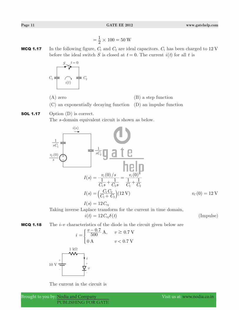
SOL 1.17 Option (D) is correct.The s -domain equivalent circuit is shown as below.
( )I s ( )/ ( )
C s C s
v s
C C
v1 1
01 1
0c c
1 2 1 2
=+
=+
( )I s (12 )VC CC C1 2
1 2= +b l (0) 12 VvC =
( )I s 12Ceq=Taking inverse Laplace transform for the current in time domain, ( )i t ( )C t12 eq δ= (Impulse)
MCQ 1.18 The i -v characteristics of the diode in the circuit given below are
i . , .
.
A V
A V
v v
v500
0 7 0 7
0 0 7<
$=
−*
The current in the circuit is

Page 12 GATE EE 2012 www.gatehelp.com
Brought to you by: Nodia and Company Visit us at: www.nodia.co.in
PUBLISHING FOR GATE
(A) 10 mA (B) 9.3 mA
(C) 6.67 mA (D) 6.2 mA
SOL 1.18 Option (D) is correct.Let 0.7 Vv > and diode is forward biased. By applying Kirchoff’s voltage law 10 1ki v#− − 0=
. ( )v v10 5000 7 1000− − −: D 0=
10 ( 0.7) 2v v#− − − 0= .v10 3 1 4− + 0=
v . 3.8 > .V311 4 0 7= = (Assumption is true)
So, .i v500
0 7= − . . 6.2 mA5003 8 0 7= − =
MCQ 1.19 The output Y of a 2-bit comparator is logic 1 whenever the 2-bit input A is greater than the 2-bit input B . The number of combinations for which the output is logic 1, is(A) 4 (B) 6
(C) 8 (D) 10
SOL 1.19 Option (B) is correct.
Y 1= , when A B> A ,a a B b b1 0 1 0= =
a1 a0 b1 b0 Y
0 1 0 0 1
1 0 0 0 1
1 0 0 1 1
1 1 0 0 1
1 1 0 1 1
1 1 1 0 1
Total combination 6=
MCQ 1.20 Consider the given circuit

Page 13 GATE EE 2012 www.gatehelp.com
Brought to you by: Nodia and Company Visit us at: www.nodia.co.in
PUBLISHING FOR GATE
In this circuit, the race around(A) does not occur
(B) occur when CLK 0=
(C) occur when 1 1andCLK A B= = =
(D) occur when 1 0andCLK A B= = =
SOL 1.20 Option (A) is correct.The given circuit is
Condition for the race-aroundIt occurs when the output of the circuit ( , )Y Y1 2 oscillates between ‘0’ and ‘1’ checking it from the options.1. Option (A): When CLK 0=Output of the NAND gate will be 0A B 11 1= = = . Due to these input to the next NAND gate, Y Y Y12 1 1:= = and 1Y Y Y21 2:= = .If Y 01 = , Y Y 12 1= = and it will remain the same and doesn’t oscillate.If Y 02 = , Y Y 11 2= = and it will also remain the same for the clock period. So, it won’t oscillate for CLK 0= .So, here race around doesn’t occur for the condition CLK 0= .2. Option (C): When , 1CLK A B1= = = A B1 1= 0= and so Y Y 11 2= =And it will remain same for the clock period. So race around doesn’t occur for the condition.3. Option (D): When , 0CLK A B1= = =So, A B1 1= 1=And again as described for Option (B) race around doesn’t occur for the condition.So, Option (A) will be correct.
MCQ 1.21 The figure shows a two-generator system applying a load of 40 MWPD = , connected at bus 2.

Page 14 GATE EE 2012 www.gatehelp.com
Brought to you by: Nodia and Company Visit us at: www.nodia.co.in
PUBLISHING FOR GATE
The fuel cost of generators G1 and G2 are :( ) 10000 /Rs MWhC PG1 1 = and ( ) 12500 /Rs MWhC PG2 2 = and the loss in the line is
. ,P P0 5( ) ( )loss pu G pu12= where the loss coefficient is specified in pu on a 100 MVA base.
The most economic power generation schedule in MW is(A) ,P P20 22G G1 2= = (B) ,P P22 20G G1 2= =
(C) ,P P20 20G G1 2= = (D) ,P P0 40G G1 2= =
SOL 1.21 Option (A) is correct.Let penalty factor of plant G , is L1 given as
L1
PP1
1
G
L
122
=−
PL . P0 5 G2
1=
PP
G
L
222 . ( )P P0 5 2 G G1 1= =
So, L1 P11
G2
= −
Penalty factor of plant G2 is
L2
PP1
1 1
G
L
222
=−
= PP 0
G
L
2
a22 =c m
For economic power generation C L1 1# C L2 2#=where C1 and C2 are the incremental fuel cost of plant G1 and G2.
So, ( ) P10000 11
G2−b l 12500 1#=
54 P1 G2= −
PG2 pu51=
It is an 100 MVA, so
PG2 100 20 MW51#= =
Loss PL 0.5 pu51
5012
= =b l
or PL 100 2 MW501
#= =

Page 15 GATE EE 2012 www.gatehelp.com
Brought to you by: Nodia and Company Visit us at: www.nodia.co.in
PUBLISHING FOR GATE
Total power, PL P P PG G L1 2= + − 40 P20 22= + − PG2 22 MW=
MCQ 1.22 The sequence components of the fault current are as follows : 1.5 ,puI jpositive = 0.5 ,puI jnegative =− 1 puI jzero =− . The type of fault in the system is
(A) LG (B) LL
(C) LLG (D) LLLG
SOL 1.22 Option (C) is correct.For double line-to-ground (LLG ) fault, relation between sequence current is Ipositive I Inegative zero=− +^ hGives values satisfy this relation, therefore the type of fault is LLG .
MCQ 1.23 A half-controlled single-phase bridge rectifier is supplying an R-L load. It is operated at a firing angle α and the load current is continuous. The fraction of cycle that the freewheeling diode conducts is(A) /1 2 (B) ( / )1 α π−
(C) /2α π (D) /α π
SOL 1.23 Option (D) is correct.The circuit of a single-phase half controlled bridge rectifier with RL load and free wheel diode is shown as below.
The voltage current wave forms are shown in figure below.

Page 16 GATE EE 2012 www.gatehelp.com
Brought to you by: Nodia and Company Visit us at: www.nodia.co.in
PUBLISHING FOR GATE
We note that, for continuous load current, the flywheel diode conducts from π to π α+ in a cycle. Thus, fraction of cycle that freewheel diode conducts is /α π .Thus fraction of cycle that freewheel diode conducts is /α π .
MCQ 1.24 The typical ratio of latching current to holding current in a 20 A thyristor is(A) 5.0 (B) 2.0
(C) 1.0 (D) 0.5
SOL 1.24 Option (B) is correct.The latching current is higher than the holding current. Usually, latching current is taken two to three times the holding currents.
MCQ 1.25 For the circuit shown in the figure, the voltage and current expressions are ( ) ( ) ( )sin sinv t E t E t31 3ω ω= + and ( ) ( ) (3 ) ( )sin sin sini t I t I t I t51 1 3 3 5ω φ ω φ ω= − + − +
The average power measured by the wattmeter is

Page 17 GATE EE 2012 www.gatehelp.com
Brought to you by: Nodia and Company Visit us at: www.nodia.co.in
PUBLISHING FOR GATE
(A) cosE I21
1 1 1φ (B) [ ]cos cosE I E I E I21
1 1 1 1 3 3 1 5φ φ+ +
(C) [ ]cos cosE I E I21
1 1 1 3 3 3φ φ+ (D) [ ]cos cosE I E I21
1 1 1 3 1 1φ φ+
SOL 1.25 Option (C) is correct.Let tω θ= , we have instaneous voltage and current as follows. ( )v t sin sinE E 31 3θ θ= + ( )i t ( ) ( ) ( )sin sin sinI I I3 51 1 3 3 5θ φ θ φ θ= − + − +We know that wattmeter reads the average power, which is gives as
P ( ) ( )v t i t d21
0
2
π θ=π
# ...(i)
We can solve this integration using following results.
(i) ( ) ( ) ( )sin sin cosA B d AB21
21
0
2:π θ α θ β θ α β+ + = −
π
#
(ii) ( ) ( ) ( )sin cos sinA B d AB21
21
0
2:π θ α θ α θ α β+ + = −
π
#
(iii) ( ) ( )sin cosA m B n d21 0
0
2:π θ α θ β θ+ + =
π
#
(iv) ( ) ( )sin cosA m B n d21 0
0
2:π θ α θ β θ+ + =
π
#
Result (iii) and (iv) implies that power is transferred between same harmonics of voltages and currents.Thus integration of equation (i) gives.
P cos cosE I E I21
21
1 1 3 3 3φ φ= +
Q. 26 to Q. 55 carry two marks each.
MCQ 1.26 Given that
andA I52
30
10
01=
− −=> >H H, the value of A3 is
(A) 15 12A I+ (B) 19 30A I+
(C) 17 15A I+ (D) 17 21A I+

Page 18 GATE EE 2012 www.gatehelp.com
Brought to you by: Nodia and Company Visit us at: www.nodia.co.in
PUBLISHING FOR GATE
SOL 1.26 Option (B) is correct.Characteristic equation. A Iλ− 0=
52
3λλ
− − −− 0=
5 62λ λ+ + 0=
5 62λ λ+ + 0=Since characteristic equation satisfies its own matrix, so 5 6A A2 + + 0= 5 6A A I2& =− −Multiplying with A 5 6A A A3 2+ + 0= 5( 5 6 ) 6A A I A3 + − − + 0= A3 19 30A I= +
MCQ 1.27 The maximum value of ( )f x x x x9 24 53 2= − + + in the interval [ , ]1 6 is(A) 21 (B) 25
(C) 41 (D) 46
SOL 1.27 Option (B) is correct. ( )f x x x x9 24 53 2= − + +
( )
dxdf x
x x3 18 24 02= − + =
& ( )
dxdf x
6 8 0x x2= − + =
x 4= , x 2=
( )
dxd f x
2
2
x6 18= −
For ,x 2= ( )
dxd f x
12 18 6 0<2
2
= − =−
So at ,x 2= ( )f x will be maximum
( )f xmax
( ) ( ) ( )2 9 2 24 2 53 2= − + + 8 36 48 5= − + + 25=
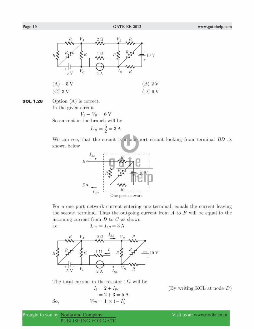
MCQ 1.28 If 6 VV VA B− = then V VC D− is
Page 19 GATE EE 2012 www.gatehelp.com
Brought to you by: Nodia and Company Visit us at: www.nodia.co.in
PUBLISHING FOR GATE
(A) 5 V− (B) V2
(C) V3 (D) V6
SOL 1.28 Option (A) is correct.In the given circuit V VA B− 6 V=So current in the branch will be
IAB 3 A26= =
We can see, that the circuit is a one port circuit looking from terminal BD as shown below
For a one port network current entering one terminal, equals the current leaving the second terminal. Thus the outgoing current from A to B will be equal to the incoming current from D to C as showni.e. IDC 3 AIAB= =
The total current in the resistor 1 Ω will be I1 2 IDC= + (By writing KCL at node D) 2 3 5 A= + =So, VCD ( )I1 1#= −

Page 20 GATE EE 2012 www.gatehelp.com
Brought to you by: Nodia and Company Visit us at: www.nodia.co.in
PUBLISHING FOR GATE
5 V=−
MCQ 1.29 The voltage gain Av of the circuit shown below is
(A) A 200v . (B) A 100v .
(C) A 20v . (D) A 10v .
SOL 1.29 Option (D) is correct.DC Analysis :
Using KVL in input loop, .V I100 0 7C B− − 0= VC .I100 0 7B= + ...(i)
IC . ( )I kV I12
13 7 1EC
B- β= − = +
. V12 1013 7 C
3#
− I100 B= ...(ii)
Solving equation (i) and (ii), IB 0.01 mA=Small Signal Analysis :Transforming given input voltage source into equivalent current source.

Page 21 GATE EE 2012 www.gatehelp.com
Brought to you by: Nodia and Company Visit us at: www.nodia.co.in
PUBLISHING FOR GATE
This is a shunt-shunt feedback amplifier.Given parameters,
rπ 0.0125 2.5mA
mV kIV
B
T Ω= = =
gm . 0.04 sr 2 5 1000100#
β= = =π
Writing KCL at output node
Rv g v R
v vC
mF
0 0+ + −π
π 0=
v R R v g R1 1 1C F
mF
0 + + −π: :D D 0=
Substituting 1 ,kR 2C Ω= 100 ,kRF Ω= 0.04 sgm = (9.33 10 ) (0.04)v v0
5# + π
− 0= v0 . V428 72=− π ...(i)Writing KCL at input node
Rv
s
i Rv
rv
Rv v
s F
o= + + −π
π
π π
Rv
s
i v R r R Rv1 1 1
s F F
0= + + −ππ
: D
Rv
s
i (5.1 10 )v Rv
F
4 0#= −π
−
Substituting Vπ from equation (i)
Rv
s
i .. v R
v428 72
5 1 10F
4
00#= − −
−
v10 10
i3
# 1.16 10 1 10v v6
05
0# #=− −− − 10 kRs Ω= (source resistance)
v10 10
i3
# .1 116 10 5
#=− −
Av .
8.96vv
10 10 1 116 101
i
03 5
# # #-= = −
MCQ 1.30 The state transition diagram for the logic circuit shown is

Page 22 GATE EE 2012 www.gatehelp.com
Brought to you by: Nodia and Company Visit us at: www.nodia.co.in
PUBLISHING FOR GATE
SOL 1.30 Option (D) is correct.Let Qn 1+ is next state and Qn is the present state. From the given below figure. D Y AX AX0 1= = + Qn 1+ D AX AX0 1= = + Qn 1+ A Q AQn n= + ,X Q X Q0 1= =If ,A 0= Qn 1+ Qn= (toggle of previous state)If ,A 1= Qn 1+ Qn=So state diagram is
MCQ 1.31 Let [ ]y n denote the convolution of [ ]h n and [ ]g n , where [ ] ( / ) [ ]h n u n1 2 n= and [ ]g n is a causal sequence. If [0] 1y = and [1] 1/2,y = then [1]g equals(A) 0 (B) /1 2
(C) 1 (D) /3 2
SOL 1.31 Option (A) id correct.Convolution sum is defined as
[ ]y n [ ] [ ] [ ] [ ]h n g n h n g n kk
= = −3
3
=−* /
For causal sequence, [ ]y n [ ] [ ]h n g n kk 0
= −3
=/

Page 23 GATE EE 2012 www.gatehelp.com
Brought to you by: Nodia and Company Visit us at: www.nodia.co.in
PUBLISHING FOR GATE
[ ]y n [ ] [ ] [ ] [ 1] [ ] [ 2] .....h n g n h n g n h n g n= + − + − +
For n 0= , [ ]y 0 [ ] [ ] [ ] [ ] ...........h g h g0 0 1 1= + − + [ ]y 0 [ ] [ ]h g0 0= [ ] [ ] ....g g1 2 0− = − = [ ]y 0 [ ] [ ]h g0 0= ...(i)
For n 1= , [ ]y 1 [ ] [ ] [ ] [ ] [ ] [ ] ....h g h g h g1 1 1 0 1 1= + + − + [ ]y 1 [ ] [ ] [ ] [ ]h g h g1 1 1 0= +
21 [ ] [ ]g g2
1 1 21 0= + [1]h 2
1211
= =b l
1 [ ] [ ]g g1 0= + [ ]g 1 [ ]g1 0= −From equation (i),
[ ]g 0 [ ][ ]
hy
00
11 1= = =
So, [ ]g 1 1 1 0= − =
MCQ 1.32 The circuit shown is a
(A) low pass filter with ( )
/rad sfR R C
1dB3
1 2= +
(B) high pass filter with /rad sf R C1
dB31
=
(C) low pass filter with /rad sf R C1
dB31
=
(D) high pass filter with ( )
/rad sfR R C
1dB3
1 2= +
SOL 1.32 Option (B) is correct.First we obtain the transfer function.

Page 24 GATE EE 2012 www.gatehelp.com
Brought to you by: Nodia and Company Visit us at: www.nodia.co.in
PUBLISHING FOR GATE
( ) ( )
j C R
V jRV j
10 0i o
12
ω
ω ω
+
− + − 0=
( )R
V jo
2
ω
( )
j C R
V j1
i
1ω
ω=+
−
( )V jo ω ( )
R j C
V j R1
i
1
2
ω
ω=−−
At 0"ω (Low frequencies)
C1
ω ," 3 so V 0o =
At " 3ω (higher frequencies)
C1
ω ,0" so ( ) ( )V j RR V jo i
1
2ω ω=−
The filter passes high frequencies so it is a high pass filter.
( )H jω VV
R j C
R1i
o
1
2
ω= =
−−
( )H 3 RR
RR
1
2
1
2= − =
At 3 dB frequency, gain will be 2 times of maximum gain ( )H 36 @
H j 0ω^ h ( )H2
1 3=
So, R
C
R1
12
02 2
2
ω+
RR
21
1
2= b l
R2 12 R
C1
12
02 2ω
= +
R12
C12 2ω
=
0ω R C11
=
MCQ 1.33 For the system below, andS SD D1 2 are complex power demands at bus 1 and bus 2 respectively. If 1 puV2 = , the VAR rating of the capacitor ( )QG2 connected at

Page 25 GATE EE 2012 www.gatehelp.com
Brought to you by: Nodia and Company Visit us at: www.nodia.co.in
PUBLISHING FOR GATE
bus 2 is
(A) 0.2 pu (B) 0.268 pu
(C) 0.312 pu (D) 0.4 pu
SOL 1.33 Option (B) is correct.Complex power for generator SG1 1 1 2 puS SD D1 2= + = + = (Line is lossless)Power transferred from bus 1 to bus 2 is 1 pu, so
1 ( )sin
XV V1 2 1 2θ θ
=−
. ( )sin0 51 1
1 2# θ θ= −
0.5
pu
puX
V V 11 2= ==
0.5 ( )sin 1 2θ θ= − 1 2θ θ− 30c= 2θ 30 301 c cθ= − =− ( )01 cθ =So, V1 1 V0c= V2 1 V30c= −
Current, I12 .1 1
Z jV V
0 50 301 2 c c= − = −
(1 0.288) puj= −Current in SD2 is I2, SD2 V I2 2= )
1 1 I30 2c= − )
I2 1 pu30c= −Current in QG2 , IG I I2 12= −
( . )j1 30 1 0 288c= − − −
.0 268 120c= −VAR rating of capacitor, QC 1 0.268 0.268 puV VG2 #= = =
MCQ 1.34 A cylinder rotor generator delivers 0.5 pu power in the steady-state to an infinite

Page 26 GATE EE 2012 www.gatehelp.com
Brought to you by: Nodia and Company Visit us at: www.nodia.co.in
PUBLISHING FOR GATE
bus through a transmission line of reactance 0.5 pu. The generator no-load voltage is 1.5 pu and the infinite bus voltage is 1 pu. The inertia constant of the generator is 5 MW- /s MVA and the generator reactance is 1 pu. The critical clearing angle, in degrees, for a three-phase dead short circuit fault at the generator terminal is(A) 53.5 (B) 60.2
(C) 70.8 (D) 79.6
SOL 1.34 Option (D) is correct.
Total reactance, X 1 0.5 1.5 puj j j= + =Critical angle is given as, crδ [( ) ]cos sin cos21
0 0 0π δ δ δ= − −− ...(i)0 "δ steady state torque angle.
Steady state power is given as Pm sinPmax 0δ=
where, Pmax XE V
=
So, Pm sinXE V
0δ=
.0 5 .( . )( )
sin1 51 5 1
0δ= 0.5 puPm =
sin 0δ .0 5= 0δ 30c=
In radian, 0δ .30180
0 523#c cπ= =
Substituting 0δ into equation (i) crδ [( . ) ]cos sin cos2 0 523 30 301
# c cπ= − −−
[( . )( . ) . ]cos 2 095 0 5 0 8661= −−
( . )cos 0 18151= −
.79 6c-
MCQ 1.35 In the circuit shown, an ideal switch S is operated at 100 kHz with a duty ratio of 50%. Given that icΔ is 1.6 A peak-to-peak and I0 is 5 A dc, the peak current in S, is

Page 27 GATE EE 2012 www.gatehelp.com
Brought to you by: Nodia and Company Visit us at: www.nodia.co.in
PUBLISHING FOR GATE
(A) 6.6 A (B) 5.0 A
(C) 5.8 A (D) 4.2 A
SOL 1.35 Option (C) is correct.
IS 5 0.8 5.8 AI i2
c0
T= + = + =
MCQ 1.36 A 220 ,V 15 ,kW 100 rpm shunt motor with armature resistance of 0.25 ,Ω has a rated line current of 68 A and a rated field current of 2.2 A. The change in field flux required to obtain a speed of 1600 rpm while drawing a line current of 52.8 A and a field current of 1.8 A is(A) 18.18% increase (B) 18.18% decrease
(C) 36.36% increase (D) 36.36% decrease
SOL 1.36 Option (D) is correct. E n\ φwhere n " speed, "φ flux and E " back emfGiven that, Vt 250 V= , 0.25Ra Ω= n1 100 rpm0= , 68 AIL1 = , 2.2 AIF1 =Armature current, Ia1 68 2.2 65.8 AI IL F1 1= − = − = E1 ,V I Rt a a= − ( . )( . )250 65 8 0 25= − 203.55 V=
Now, n2 1600 rpm= , 52.8 AIL2 = , 1.8 AIF2 =Armature current, Ia2 I IL F2 2= − . .52 8 1 8= − 51 A= E2 V I Rt a a2= − ( )( . )220 51 0 25= − 207.25 V=
EE
2
1 nn
2
1
2
1
φφ= a ck m
..
207 45203 55 1600
10002
1
φφ= b cl m

Page 28 GATE EE 2012 www.gatehelp.com
Brought to you by: Nodia and Company Visit us at: www.nodia.co.in
PUBLISHING FOR GATE
2φ .0 6369 1φ=
% reduce in flux 1001
1 2#φ
φ φ= −
. 1000 63691
1 1
φφ φ
#= −
. %36 3-
MCQ 1.37 A fair coin is tossed till a head appears for the first time. The probability that the number of required tosses is odd, is(A) /1 3 (B) /1 2
(C) /2 3 (D) /3 4
SOL 1.37 Option (C) is correct.Probability of appearing a head is /1 2. If the number of required tosses is odd, we have following sequence of events. ,H ,TTH , ...........TTTTH
Probability P .....21
21
213 5
= + + +b bl l
P 21
1 41 3
2=−
=
MCQ 1.38 The direction of vector A is radially outward from the origin, with krA n= . where r x y z2 2 2 2= + + and k is a constant. The value of n for which A 0:d = is(A) 2− (B) 2
(C) 1 (D) 0
SOL 1.38 Option (A) is correct.Divergence of A in spherical coordinates is given as
A:d ( )r r
r A1r2
2
22=
( )r r
kr1 n2
2
22= +
( )rk n r2 n2
1= + +
( )k n r2 0n 1= + =− (given) n 2+ 0= n 2=−
MCQ 1.39 Consider the differential equation
( ) ( )
( )dt
d y tdt
dy ty t22
2
+ + ( )tδ= with ( ) 2 0andy t dtdy
tt
00
=− ==
=−
−

Page 29 GATE EE 2012 www.gatehelp.com
Brought to you by: Nodia and Company Visit us at: www.nodia.co.in
PUBLISHING FOR GATE
The numerical value of dtdy
t 0= +
is(A) 2− (B) 1−
(C) 0 (D) 1
SOL 1.39 Option (D) is correct.
( ) ( )
( )dt
d y tdtdy t
y t2
2
2
+ + ( )tδ=
By taking Laplace transform with initial conditions
( ) ( ) [ ( ) ( )] ( )s Y s sy dtdy sy s y Y s0 2 0
t
2
0− − + − +
=; E 1=
& ( ) 2 ( ) ( )s Y s s sY s Y s2 0 22 + − + + +6 6@ @ 1=
( ) [ ]Y s s s2 12 + + s1 2 4= − −
( )Y s s s
s2 1
2 32=+ +
− −
We know that,If, ( )y t ( )Y sL
then, ( )
dtdy t
( ) ( )sY s y 0L −
So, ( ) ( )sY s y 0− ( )( )s s
s s2 1
2 322=
+ +− − +
( )s s
s s s s2 1
2 3 2 4 22
2 2
=+ +
− − + + +
( ) ( )sY s y 0− ( ) ( ) ( )ss
ss
s12
11
11
2 2 2=++ =
++ +
+
( )s s1
11
12= + +
+By taking inverse Laplace transform
( )
dtdy t
( ) ( )e u t te u tt t= +− −
At t 0= +, dtdy
t 0= +
e 0 10= + =
MCQ 1.40 Assuming both the voltage sources are in phase, the value of R for which maximum power is transferred from circuit A to circuit B is

Page 30 GATE EE 2012 www.gatehelp.com
Brought to you by: Nodia and Company Visit us at: www.nodia.co.in
PUBLISHING FOR GATE
(A) 0.8 Ω (B) 1.4 Ω
(C) 2 Ω (D) 2.8 Ω
SOL 1.40 Option (A) is correct.We obtain Thevenin equivalent of circuit B .
Thevenin Impedance :
ZTh R=Thevenin Voltage : VTh 3 V0c=Now, circuit becomes as
Current in the circuit, I1 R210 3= +
−
Power transfer from circuit toA B P ( ) 3I R I1
2 21= +
P 10 3 10 3R R R2 3 2
2= +
− + +−
: :D D
P ( ) ( )R
RR2
492
212=
++ +
P ( )
( )R
R R2
49 21 22=
++ +

Page 31 GATE EE 2012 www.gatehelp.com
Brought to you by: Nodia and Company Visit us at: www.nodia.co.in
PUBLISHING FOR GATE
P ( )42 70
RR
2 2=++
dRdP
( )( ) ( ) ( )
RR R R
22 70 42 70 2 2
04
2
=+
+ − + + =
(2 )[(2 )70 (42 70 )2]R R R+ + − + 0= R R140 70 84 140+ − − 0= 56 R70= R 0.8 Ω=
MCQ 1.41 The state variable description of an LTI system is given by
xxx
1
2
3
o
o
o
J
L
KKK
N
P
OOO
0
a
aa
xxx
u00 0
0 0
0013
1
2
1
2
3
= +
J
L
KKK
J
L
KKK
J
L
KKK
N
P
OOO
N
P
OOO
N
P
OOO
y xxx
1 0 01
2
3
=
J
L
KKK
_
N
P
OOO
i
where y is the output and u is the input. The system is controllable for(A) 0, 0, 0a a a1 2 3! != (B) 0, 0, 0a a a1 2 3! !=
(C) 0, 0, 0a a a1 3 3!= = (D) 0, 0, 0a a a1 2 3! ! =
SOL 1.41 Option (D) is correct.General form of state equations are given as xo x uA B= + yo x uC D= +For the given problem
A 0
,a
aa
00 0
0 03
1
2=
R
T
SSSS
V
X
WWWW
B001
=
R
T
SSSS
V
X
WWWW
AB 0
a
aa a
00 0
0 0
001
0
03
1
2 2= =
R
T
SSSS
R
T
SSSS
R
T
SSSS
V
X
WWWW
V
X
WWWW
V
X
WWWW
A B2 a aa a
a a a a0
0
00 0
0
001
00
2 3
3 1
1 2 1 2
= =
R
T
SSSS
R
T
SSSS
R
T
SSSS
V
X
WWWW
V
X
WWWW
V
X
WWWW
For controllability it is necessary that following matrix has a tank of n 3= . U : :B AB A B2= 6 @
0
aa a0
01 0
00
2
1 2
=
R
T
SSSS
V
X
WWWW
So, a2 0!
Page 32 GATE EE 2012 www.gatehelp.com
Brought to you by: Nodia and Company Visit us at: www.nodia.co.in
PUBLISHING FOR GATE
a a1 2 0! a 01& !
a3 may be zero or not.
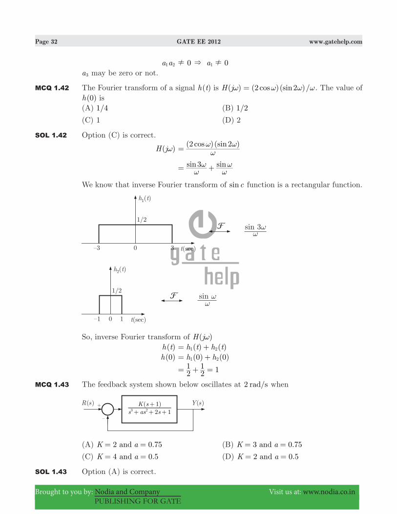
MCQ 1.42 The Fourier transform of a signal ( )h t is ( ) ( )( )/cos sinH j 2 2ω ω ω ω= . The value of ( )h 0 is
(A) /1 4 (B) /1 2
(C) 1 (D) 2
SOL 1.42 Option (C) is correct.
( )H jω ( )( )cos sin2 2
ωω ω=
sin sin3ω
ωω
ω= +
We know that inverse Fourier transform of sinc function is a rectangular function.
So, inverse Fourier transform of ( )H jω ( )h t ( ) ( )h t h t1 2= + ( )h 0 (0) (0)h h1 2= +
21
21 1= + =
MCQ 1.43 The feedback system shown below oscillates at 2 /rad s when
(A) 2 0.75andK a= = (B) 3 0.75andK a= =
(C) 4 0.5andK a= = (D) 2 0.5andK a= =
SOL 1.43 Option (A) is correct.

Page 33 GATE EE 2012 www.gatehelp.com
Brought to you by: Nodia and Company Visit us at: www.nodia.co.in
PUBLISHING FOR GATE
( )Y s ( )
[ ( ) ( )]s as s
K sR s Y s
2 11
3 2=+ + +
+ −
( )( )
Y ss as s
K s1
2 11
3 2++ + +
+; E
( )( )
s as sK s
R s2 11
3 2=+ + +
+
( ) [ ( ) ( )]Y s s as s k k2 13 2+ + + + + ( 1) ( )K s R s= +Transfer Function
( )( )( )
H sR sY s=
( ) ( )( )
s as s k kK s
2 11
3 2=+ + + + +
+
Routh Table :
For oscillation,
( ) ( )
aa K K2 1+ − +
0=
a KK
21= +
+
Auxiliary equation ( )A s ( )as k 1 02= + + =
s2 ak 1=− +
s2 ( )
( )kk k
11 2= +
− + +
s2 ( )k 2=− + s j k 2= + jω j k 2= + ω k 2 2= + = (Oscillation frequency) k 2=
and a .2 22 1
43 0 75= +
+ = =
MCQ 1.44 The input ( )x t and output ( )y t of a system are related as ( ) ( ) (3 )cosy t x dt
τ τ τ=3−
#. The system is (A) time-invariant and stable (B) stable and not time-invariant
(C) time-invariant and not stable (D) not time-invariant and not stable
SOL 1.44 Option (D) is correct.
( )y t ( ) ( )cosx d3t
τ τ τ=3−
#
Time invariance :

Page 34 GATE EE 2012 www.gatehelp.com
Brought to you by: Nodia and Company Visit us at: www.nodia.co.in
PUBLISHING FOR GATE
Let, ( )x t ( )tδ=
( )y t ( ) ( )cost d3tδ τ τ=3−
#
( ) (0)cosu t= ( )u t=For a delayed input ( )t t0− output is
( , )y t t0 ( ) ( )cost t d3t
0δ τ τ= −3−
#
( ) (3 )cosu t t0=Delayed output ( )y t t0− ( )u t t0= − ( , )y t t0 ( )y t t0! −System is not time invariant.Stability :Consider a bounded input ( ) cosx t t3=
( )y t cos cost t3 21 6t t
2= = −3 3− −
# #
cosdt t dt21 1 2
1 6t t
= −3 3− −
# #
As ,t " 3 ( )y t " 3 (unbounded)System is not stable.
MCQ 1.45 An analog voltmeter uses external multiplier settings. With a multiplier setting of 20 kΩ, it reads 440 V and with a multiplier setting of 80 kΩ, it reads 352 V. For a multiplier setting of 40 kΩ, the voltmeter reads(A) 371 V (B) 383 V
(C) 394 V (D) 406 V
SOL 1.45 Option (D) is correct.A voltmeter with a multiplier is shown in figure below.
Here Im = Fully scale deflection current of meter. Rm = Internal resistance of meter Rs = Voltage across the meter

Page 35 GATE EE 2012 www.gatehelp.com
Brought to you by: Nodia and Company Visit us at: www.nodia.co.in
PUBLISHING FOR GATE
V = Full range voltage of instrument Vm I Rm m= V ( )I R Rm m s= +
VV
m R
R RRR1
m
m s
m
s= + = +
Here when, Rs1 20 kΩ= , 440 VVm1 =
So, V440 1 20k
Rm= + ...(i)
When, Rs2 80 kΩ= , 352 VVm2 =
So, V352 1 80 k
Rm= + ...(ii)
Solving equation (i) and (ii), we get V 480 V= , 220 kRm Ω=So when Rs3 40 kΩ= , ?Vm3 =
V480
m3 1 220
40kk= +
Vm2 406 V-
MCQ 1.46 The locked rotor current in a 3-phase, star connected 15 ,kW 4 ,pole ,V230 50 Hz induction motor at rated conditions is 50 A. Neglecting losses and magnetizing current, the approximate locked rotor line current drawn when the motor is connected to a 236 ,V Hz57 supply is(A) 58.5 A (B) 45.0 A
(C) 42.7 A (D) 55.6 A
SOL 1.46 Option (B) is correct.Given that magnetizing current and losses are to be neglected. Locked rotor line current.
I2 ZE
R XE
2
2
22
22
2= =+
( )R 02 =
I2 XE
2
2=
I2 LE
2
2
ω=
I2 fE2\
So I50
2l 236
2305057= b bl l
I2l 45.0 A=
MCQ 1.47 A single phase 10 ,kVA 50 Hz transformer with 1 kV primary winding draws 0.5 A

Page 36 GATE EE 2012 www.gatehelp.com
Brought to you by: Nodia and Company Visit us at: www.nodia.co.in
PUBLISHING FOR GATE
and 55 ,W at rated voltage and frequency, on no load. A second transformer has a core with all its linear dimensions 2 times the corresponding dimensions of the first transformer. The core material and lamination thickness are the same in both transformer. The primary winding of both the transformers have the save number of turns. If a rate voltage of 2 kV at 50 Hz is applied to the primary of the second transformer, then the no load current and power, respectively, are(A) 0.7 ,A 77.8 A (B) 0.7 ,A 155.6 W
(C) 1 ,A 110 W (D) 1 ,A 220 W
SOL 1.47 Option (B) is correct.Since the core length of the second transformer is 2 times of the first, so the core area of the second transformer is twice of the first.Let subscript 1 is used for first transformer and 2 is used for second transform.Area a2 a2 1=Length l2 l2 1=
Magnetizing inductance, L lN a2μ=
N = no. of turns μ = length of flux path a = cross section area l = length
L la
\ N and μ are same for both the transformer
LL
2
1 aa
ll
2
1
1
2:=
LL
2
1 aa
ll
22
1
1
1
1:=
L2 L2 1=Thus, magnetizing reactance of second transformer is 2 times of first.Magnetizing current Xm2 X2 m1=
Im XV
m=
IIm
m
2
1 VV
XX
m
m
2
1
1
2:=
VV
XX
22
m
m
1
1
1
1= b cl m ( )V V22 1=
Im2 I2 m1=Thus, magnetizing current of second transformer Im2 0.5 0.707 A2 #= =Since voltage of second transformer is twice that of first and current is 2 times that of first, so power will be 2 2 times of first transformer. P2 2 55 155.6 W2 #= =

Page 37 GATE EE 2012 www.gatehelp.com
Brought to you by: Nodia and Company Visit us at: www.nodia.co.in
PUBLISHING FOR GATE
Common Data Question
Common Data for Questions 48 and 49In the 3-phase inverter circuit shown, the load is balanced and the gating scheme is 180c conduction mode. All the switching devices are ideal.
MCQ 1.48 The rms value of load phase voltage is(A) 106.1 V (B) 141.4 V
(C) 212.2 V (D) 282.8 V
SOL 1.48 Option (B) is correct.For a three-phase bridge inverter, rms value of output line voltage is
VL V32
dc=
30032#= 300 VVdc =
141.4 V=
MCQ 1.49 If the dc bus voltage 300 ,VVd = the power consumed by 3-phase load is(A) 1.5 kW (B) 2.0 kW
(C) 2.5 kW (D) 3.0 kW
SOL 1.49 Option (D) is correct.
P RV3 L
2
#=
( . )
3 20141 4 2
#=
3 kW-
Common Data for Questions 50 and 51 :With 10 V dc connected at port A in the linear nonreciprocal two-port network shown below, the following were observed :(i) 1 Ω connected at port B draws a current of 3 A

Page 38 GATE EE 2012 www.gatehelp.com
Brought to you by: Nodia and Company Visit us at: www.nodia.co.in
PUBLISHING FOR GATE
(ii) 2.5 Ω connected at port B draws a current of 2 A
MCQ 1.50 With 10 V dc connected at port A, the current drawn by 7 Ω connected at port B is(A) 3/7 A (B) 5/7 A
(C) 1 A (D) 9/7 A
SOL 1.50 Option (C) is correct.When 10 V is connected at port A the network is
Now, we obtain Thevenin equivalent for the circuit seen at load terminal, let Thevenin voltage is V , VTh 10 with 10 V applied at port A and Thevenin resistance is RTh .
IL R RV ,10 V
Th L
Th= +
For 1RL Ω= , 3 AIL =
3 RV
1,10 V
Th
Th= + ...(i)
For 2.5RL Ω= , 2 AIL =
.RV
2 5,10 V
Th
Th= + ...(ii)
Dividing above two
23 .
RR
12 5
Th
Th= ++
R3 3Th + R2 5Th= +

Page 39 GATE EE 2012 www.gatehelp.com
Brought to you by: Nodia and Company Visit us at: www.nodia.co.in
PUBLISHING FOR GATE
RTh 2 Ω=Substituting RTh into equation (i) V ,10 VTh 3(2 1) 9 V= + =Note that it is a non reciprocal two port network. Thevenin voltage seen at port B depends on the voltage connected at port A. Therefore we took subscript V ,10 VTh . This is Thevenin voltage only when 10 V source is connected at input port .A If the voltage connected to port A is different, then Thevenin voltage will be different. However, Thevenin’s resistance remains same.Now, the circuit is
For 7RL Ω=
IL 1 ARV2 2 7
9,10 V
L
Th= + = + =
MCQ 1.51 For the same network, with 6 V dc connected at port A, 1 Ω connected at port B draws 7/3 .A If 8 V dc is connected to port A, the open circuit voltage at port B is(A) 6 V (B) 7 V
(C) 8 V (D) 9 V
SOL 1.51 Option (B) is correct.Now, when 6 V connected at port A let Thevenin voltage seen at port B is V ,6 VTh .
Here 1RL Ω= and AI 37
L =
V , VTh 6 R 37 1 3
7Th # #= +
2 7 V37
37
#= + =
This is a linear network, so VTh at port B can be written as VTh V1α β= +where V1 is the input applied at port A.We have 10 VV1 = , 9 VV ,10 VTh =

Page 40 GATE EE 2012 www.gatehelp.com
Brought to you by: Nodia and Company Visit us at: www.nodia.co.in
PUBLISHING FOR GATE
9 10α β= + ...(i)When 6 VV1 = , 9 VV , VTh 6 =
7 6α β= + ...(ii)Solving (i) and (ii) α .0 5= , 4β =Thus, with any voltage V1 applied at port A, Thevenin voltage or open circuit voltage at port B will beSo, V ,Th V1 . V0 5 41= +For V1 8 V= V ,8 VTh . V0 5 8 4 8 oc#= + = = (open circuit voltage)
Linked Answer Question
Statement for Linked Answer Questions 52 and 53 :In the circuit shown, the three voltmeter readings are 220 ,VV1 = 122 ,VV2 =
136 VV3 = .
MCQ 1.52 The power factor of the load is(A) 0.45 (B) 0.50
(C) 0.55 (D) 0.60
SOL 1.52 Option (A) is correct.By taking ,V V1 2 and V3 all are phasor voltages. V1 V V2 3= +Magnitude of ,V V1 2 and V3 are given as V1 220 V= , 122 VV2 = , 136 VV3 =Since voltage across R is in same phase with V1 and the voltage V3 has a phase difference of θ with voltage V1, we write in polar form V1 V V02 3c θ= + V1 cos sinV V jV2 3 3θ θ= + + V1 ( )cos sinV V jV2 3 3θ θ= + + V1 ( ) ( )cos sinV V V2 3
22
2θ θ= + + 220 ( ) ( )cos sin122 136 1362 2θ θ= + +

Page 41 GATE EE 2012 www.gatehelp.com
Brought to you by: Nodia and Company Visit us at: www.nodia.co.in
PUBLISHING FOR GATE
By solving, power factor cosθ .0 45=
MCQ 1.53 If 5RL Ω= , the approximate power consumption in the load is(A) 700 W (B) 750 W
(C) 800 W (D) 850 W
SOL 1.53 Option (B) is correct.Voltage across load resistance VRL cosV3 θ= .136 0 45#= 61.2 V=Power absorbed in RL
PL ( . )
750 WRV
561 2
L
RL2 2
-= =
Statement for Linked Answer Questions 54 and 55 :The transfer function of a compensator is given as
( )G sc s bs a= +
+
MCQ 1.54 ( )G sc is a lead compensator if(A) 1, 2a b= = (B) 3, 2a b= =
(C) 3, 1a b=− =− (D) 3, 1a b= =
SOL 1.54 Option (A) is correct.
( )G sC s bs a
j bj aωω= +
+ = ++
Phase lead angle
φ tan tana b1 1ω ω= −− −a ak k
φ tan
ab
a b
1
12ω
ω ω=
+
−−
J
L
KKK
N
P
OOO
( )
tanab
b a12ω
ω=+−−
c m
For phase-lead compensation 0>φ b a− 0> b a>Note: For phase lead compensator zero is nearer to the origin as compared to pole, so option (C) can not be true.
MCQ 1.55 The phase of the above lead compensator is maximum at

Page 42 GATE EE 2012 www.gatehelp.com
Brought to you by: Nodia and Company Visit us at: www.nodia.co.in
PUBLISHING FOR GATE
(A) /rad s2 (B) /rad s3
(C) /rad s6 (D) 1/ /rad s3
SOL 1.55 Option (A) is correct.
φ tan tana b1 1ω ω= −− −a ak k
ddωφ
/ /
a
a
b
b
1
1
1
10
2 2ω ω=+
−+
=a ak k
a ab1
2
2ω+ b b a1 1
2
2ω= +
a b1 1− ab a b
1 12ω= −b l
ω ab= / secrad1 2 2#= =
General Aptitude (GA) Question (Compulsory)
Q. 56 - Q. 60 carry one mark each.
MCQ 1.56 One of the parts (A, B, C, D) in the sentence given below contains an ERROR. Which one of the following is INCORRECT ?I requested that he should be given the driving test today instead of tomorrow.(A) requested that (B) should be given
(C) the driving test (D) instead of tomorrow
SOL 1.56 Option (B) is correct.
MCQ 1.57 If ( . ) .1 001 3 521259 = and ( . ) . ,1 001 7 852062 = then ( . )1 001 3321
(A) .2 23 (B) .4 33
(C) .11 37 (D) .27 64
SOL 1.57 Option (D) is correct option.Let .1 001 x=So in given data : x1259 .3 52= x2062 .7 85=Again x3321 x1259 2062= +
x x1259 2062= . .3 52 7 85#= .27 64=

Page 43 GATE EE 2012 www.gatehelp.com
Brought to you by: Nodia and Company Visit us at: www.nodia.co.in
PUBLISHING FOR GATE
MCQ 1.58 Choose the most appropriate alternate from the options given below to complete the following sentence :If the tired soldier wanted to lie down, he..................the mattress out on the balcony.(A) should take (B) shall take
(C) should have taken (D) will have taken
SOL 1.58 Option (C) is correct.
MCQ 1.59 Choose the most appropriate word from the options given below to complete the following sentence :Give the seriousness of the situation that he had to face, his........was impressive.(A) beggary (B) nomenclature
(C) jealousy (D) nonchalance
SOL 1.59 Option (D) is correct.
MCQ 1.60 Which one of the following options is the closest in meaning to the word given below ?Latitude(A) Eligibility (B) Freedom
(C) Coercion (D) Meticulousness
SOL 1.60 Option (B) is correct.
Q. 61 - Q. 65 carry two marks each.
MCQ 1.61 A and B are friends. They decide to meet between 1 PM and 2 PM on a given day. There is a conditions that whoever arrives first will not wait for the other for more than 15 minutes. The probability that they will meet on that days is(A) /1 4 (B) /1 16
(C) /7 16 (D) /9 16
SOL 1.61 Option (C) is correct.The graphical representation of their arriving time so that they met is given as below in the figure by shaded region.

Page 44 GATE EE 2012 www.gatehelp.com
Brought to you by: Nodia and Company Visit us at: www.nodia.co.in
PUBLISHING FOR GATE
So, the area of shaded region is given by Area of PQRS4 (Area of EFQT− + Area of GSHT )
60 60 2 21 45 45# # #= − b l
1575=
So, the required probability 36001575
167= =
MCQ 1.62 One of the legacies of the Roman legions was discipline. In the legious, military law prevailed and discipline was brutal. Discipline on the battlefield kept units obedient, intact and fighting, even when the odds and conditions were against them.Which one of the following statements best sums up the meaning of the above passage ?(A) Through regimentation was the main reason for the efficiency of the Roman
legions even in adverse circumstances.
(B) The legions were treated inhumanly as if the men were animals
(C) Disciplines was the armies inheritance from their seniors
(D) The harsh discipline to which the legions were subjected to led to the odds and conditions being against them.
SOL 1.62 Option (A) is correct.
MCQ 1.63 Raju has 14 currency notes in his pocket consisting of only Rs. 20 notes and Rs. 10 notes. The total money values of the notes is Rs. 230. The number of Rs. 10 notes that Raju has is(A) 5 (B) 6
(C) 9 (D) 10

Page 45 GATE EE 2012 www.gatehelp.com
Brought to you by: Nodia and Company Visit us at: www.nodia.co.in
PUBLISHING FOR GATE
SOL 1.63 Option (A) is correct.Let no. of notes of Rs.20 be x and no. of notes of Rs. 10 be y .Then from the given data. x y+ 14= x y20 10+ 230=Solving the above two equations we get x 9= , y 5=So, the no. of notes of Rs. 10 is 5.
MCQ 1.64 There are eight bags of rice looking alike, seven of which have equal weight and one is slightly heavier. The weighing balance is of unlimited capacity. Using this balance, the minimum number of weighings required to identify the heavier bag is(A) 2 (B) 3
(C) 4 (D) 8
SOL 1.64 Option (A) is correct.We will categorize the 8 bags in three groups as :(i) A A A1 2 3, (ii) B B B1 2 3, (iii) C C1 2
Weighting will be done as bellow :1st weighting " A A A1 2 3 will be on one side of balance and B B B1 2 3 on the other. It may have three results as described in the following cases.Case 1 : A A A1 2 3 = B B B1 2 3
This results out that either C1 or C2 will heavier for which we will have to perform weighting again.2nd weighting " C1 is kept on the one side and C2 on the other.if C1 C> 2 then C1 is heavier. C1 C< 2 then C2 is heavier.Case 2 : A A A21 3 B B B> 1 2 3
it means one of the A A A1 2 3 will be heavier So we will perform next weighting as:2nd weighting " A1 is kept on one side of the balance and A2 on the other.if A1 A2= it means A3 will be heavier A1 A> 2 then A1 will be heavier A1 A< 2 then A2 will be heavierCase 3 : A A A1 2 3 B B B< 1 2 3
This time one of the B B B1 2 3 will be heavier, So again as the above case weighting will be done.2nd weighting " B1 is kept one side and B2 on the otherif B1 B2= B3 will be heavier B1 B> 2 B1 will be heavier B1 B< 2 B2 will be heavierSo, as described above, in all the three cases weighting is done only two times to give out the result so minimum no. of weighting required = 2.

Page 46 GATE EE 2012 www.gatehelp.com
Brought to you by: Nodia and Company Visit us at: www.nodia.co.in
PUBLISHING FOR GATE
MCQ 1.65 The data given in the following table summarizes the monthly budget of an average household.
Category Amount (Rs.)
Food 4000
Clothing 1200
Rent 2000
Savings 1500
Other expenses 1800
The approximate percentages of the monthly budget NOT spent on savings is
(A) 10% (B) 14%
(C) 81% (D) 86%
SOL 1.65 Option (D) is correct. Total budget 4000 1200 2000 1500 1800= + + + + ,10 500=The amount spent on saving 1500=So, the amount not spent on saving ,10 500 1500 9000= − =So, percentage of the amount
%105009000 100#=
%86=