Gas/Propane Furnace Induced Draft Highboy - Thermo Pride
61
INDUCED DRAFT HIGHBOY AND COUNTERFLOW/HORIZONTAL GAS FURNACE INSTALLATION AND SERVICE MANUAL MODELS MHA1-50N MDA1-50N MHA1-75N MDA1-75N MHA1-100N MDA1-100N MHA1-125N MDA1-125N : IF YOU DO NOT FOLLOW THE SAFETY PRECAUTIONS BELOW AND IN THIS MANUAL, A FIRE OR EXPLOSION MAY RESULT CAUSING PROPERTY DAMAGE, PERSONAL INJURY, OR LOSS OF LIFE. DO NOT STORE OR USE GASOLINE OR OTHER FLAMMABLE VAPORS AND LIQUIDS IN THE VICINITY OF THIS OR ANY OTHER APPLIANCE. WHAT TO DO IF YOU SMELL GAS: • DO NOT TRY TO LIGHT ANY APPLIANCE. • DO NOT TOUCH ANY ELECTRICAL SWITCH; DO NOT USE ANY PHONE IN YOUR BUILDING. • LEAVE THE BUILDING IMMEDIATELY. • IMMEDIATELY CALL YOUR GAS SUPPLIER FROM A NEIGHBOR’S PHONE. FOLLOW THE GAS SUPPLIER’S INSTRUCTIONS. • IF YOU CANNOT REACH YOUR GAS SUPPLIER; CALL THE FIRE DEPARTMENT. INSTALLATION AND SERVICE MUST BE PERFORMED BY A QUALIFIED INSTALLER, SERVICE AGENCY OR THE GAS SUPPLIER. (REFERRED TO IN THESE INSTRUCTIONS AS A QUALIFIED HEATING CONTRACTOR). PLEASE READ THESE INSTRUCTIONS PRIOR TO INSTALLATION, INITIAL FIRING, AND BEFORE PERFORMING ANY SERVICE OR MAINTENANCE. THESE INSTRUCTIONS MUST BE LEFT WITH THE HOMEOWNER AND SHOULD BE RETAINED FOR FUTURE REFERENCE BY QUALIFIED SERVICE PERSONNEL. THERMO PRODUCTS, LLC. BOX 217 MG-1008 NORTH JUDSON, IN 46366 ECN 4283-MA PHONE: (574) 896-2133 MADE IN USA
Transcript of Gas/Propane Furnace Induced Draft Highboy - Thermo Pride
INDUCED DRAFT HIGHBOY AND COUNTERFLOW/HORIZONTAL
GAS FURNACE
INSTALLATION AND SERVICE MANUAL MODELS
MHA1-50N MDA1-50N MHA1-75N MDA1-75N MHA1-100N MDA1-100N MHA1-125N MDA1-125N
: IF YOU DO NOT FOLLOW THE SAFETY PRECAUTIONS BELOW AND IN THIS MANUAL, A FIRE OR EXPLOSION MAY RESULT CAUSING PROPERTY DAMAGE, PERSONAL INJURY, OR LOSS OF LIFE.
DO NOT STORE OR USE GASOLINE OR OTHER FLAMMABLE VAPORS AND LIQUIDS IN THE VICINITY OF THIS OR ANY OTHER APPLIANCE.
WHAT TO DO IF YOU SMELL GAS:
• DO NOT TRY TO LIGHT ANY APPLIANCE. • DO NOT TOUCH ANY ELECTRICAL SWITCH; DO NOT USE ANY PHONE IN YOUR BUILDING. • LEAVE THE BUILDING IMMEDIATELY. • IMMEDIATELY CALL YOUR GAS SUPPLIER FROM A NEIGHBOR’S PHONE. FOLLOW THE GAS
SUPPLIER’S INSTRUCTIONS. • IF YOU CANNOT REACH YOUR GAS SUPPLIER; CALL THE FIRE DEPARTMENT.
INSTALLATION AND SERVICE MUST BE PERFORMED BY A QUALIFIED INSTALLER, SERVICE AGENCY OR THE GAS SUPPLIER. (REFERRED TO IN THESE INSTRUCTIONS AS A QUALIFIED HEATING CONTRACTOR).
PLEASE READ THESE INSTRUCTIONS PRIOR TO INSTALLATION, INITIAL FIRING, AND BEFORE PERFORMING ANY SERVICE OR MAINTENANCE. THESE INSTRUCTIONS MUST BE LEFT WITH THE HOMEOWNER AND SHOULD BE RETAINED FOR FUTURE REFERENCE BY QUALIFIED SERVICE PERSONNEL.
THERMO PRODUCTS, LLC. BOX 217
MG-1008 NORTH JUDSON, IN 46366 ECN 4283-MA PHONE: (574) 896-2133
MADE IN USA

Contents SECTION PAGE Notice to the Installer ..............................................................................................1
I. SAFETY ..............................................................................................................2
II. INSTALLATION GUIDELINES .............................................................................3 A. Codes .........................................................................................................3 B. Installation Location ..................................................................................4 C. Closet and Alcove Installation ..................................................................4 D. Standard Clearances....................................................................................5 E. Air for Combustion and Ventilation...............................................................6 F. MDA1 Horizontal Installation ........................................................................7 G. Duct Work and Air Conditioning ...................................................................9 H. Filter/Filter Installation ..................................................................................9 I. Use of Non Thermo Pride Filter Retention Means........................................10 J. Venting .........................................................................................................12
1. Vertical Venting..................................................................................12 2. Replacing an Existing Furnace from a Common................................13 3. Condensing in Chimney .....................................................................14 4. Vent Flue/Vent Connector..................................................................16
K. Sidewall Venting...........................................................................................19 1. Horizontal Size and Lengths for Horizontal Vents..............................20 L. Gas/Gas Piping ............................................................................................21 1. Installation of Natural Gas Piping.......................................................23 2. Installation of Propane Gas Piping.....................................................24 M. Electrical .......................................................................................................26 1. Wiring.................................................................................................26 2. Field Wiring and Replacing Wiring.....................................................26 3. Electronic Air Cleaner and Humidifier Connections ...........................27 4. Room Thermostat ..............................................................................27 5. Blower Motor Speed Wiring ...............................................................28
III. INITIAL OPERATION OF THE FURNACE .......................................................29 A. Initial Startup ................................................................................................29 B. Adjustment of Heat Input Rate .....................................................................32 C. Burner Adjustment .......................................................................................34 D. Setting Supply Air Temperature Rise ...........................................................35 E. Checkout Procedure.....................................................................................36 IV. TROUBLESHOOTING......................................................................................37 V. DEALER MAINTENANCE .................................................................................38 A. Electrical.......................................................................................................38 B. General Inspection .......................................................................................38 C. House Air Blower..........................................................................................39 D. Return Air Filter ............................................................................................40
All installations and services must be performed by qualified service personnel.
VI. INSTALLER’S INSTRUCTIONS TO USER ......................................................41 APPENDIX A: SOURCES FOR REFERENCED STANDARDS .......................42 APPENDIX B: SEQUENCE OF OPERATION ..................................................43 APPENDIX C: TROUBLESHOOTING FLOWCHART ......................................45 APPENDIX D: PARTS PACKAGE COMPONENTS .........................................49 APPENDIX E: REPLACEMENT PARTS LIST..................................................50 APPENDIX F: ELECTRICAL DIAGRAMS ........................................................54 WARRANTY ......................................................................................................59

All installations and services must be performed by qualified service personnel.
1
Notice to the Installer
Installation of this gas-fired furnace must be performed by a qualified installer in accordance with all local codes and authorities having jurisdiction. In the absence of local governing codes, installation shall conform to these instructions and to the regulations of the National Fuel Gas Code, ANSI Z223.1/NFPA 54-2002 and/or, National Gas and Propane Installation Codes CSA B149.1, or the latest editions thereof. A qualified installer, also referred to in this instruction manual as a “qualified heating contractor”, is an individual, or agency, that is responsible for the installation and adjustment of the equipment. A qualified installer is properly licensed and experienced to install gas-burning equipment in accordance with all local codes and ordinances. Any reference to L.P. or propane gas in this manual, any other label, or markings on the furnace is to be construed to be propane HD-5, a commercial grade of liquefied petroleum gases composed of a minimum of 90 percent liquid propane (C3H8).
Material and Workmanship
This furnace was built with the highest quality materials and attention to workmanship. However, omissions and defects occasionally occur. Before installing the furnace, inspect the furnace thoroughly. If missing parts, defective material, or poor workmanship are evident, report the model and serial numbers imprinted on the furnace rating label to the seller.
Packaging
This is a complete, factory-assembled furnace contained within one package. However, certain parts, including, air filter(s), air filter rack(s), the venting system must be assembled to the furnace, in the field.
Shipping Damage If this furnace was damaged during transit, please immediately request the transportation company inspect the furnace and issue a concealed damage report. The party receiving the furnace should file the claim for shipping damage. Report any shipping damage immediately.

All installations and services must be performed by qualified service personnel.
2
It is absolutely essential that a damage report be obtained. If a concealed damage report is not obtained, we cannot provide assistance in recovering your claim against the transportation company.
Warranties
: The manufacturer of this equipment assumes no liability for any damages resulting from unauthorized modifications made to the furnace, or components thereof, or improper installation of the furnace in the field. Furthermore, any such field modifications VOID THE WARRANTY and place the responsibility for safe and reliable operation of the furnace on those who performed the modification(s).
Make certain the warranty cards are returned. These must be on file to verify installation dates for replacement of any warranted part(s).
I. Safety
: The following guidelines and warnings should be read and understood before continuing with the installation of this furnace. Failure to follow these guidelines can result in improper and unsafe operation of this appliance, which can cause substantial property damage, severe personal injury, or death.
These instructions must be read in their entirety before installing the furnace. It is the installer's responsibility to do the following:
1. Use only with the type of gas approved for this furnace. Refer to the furnace
marking plate.
2. Install this furnace only in a location and position as specified in Section II, B of this manual.
3. Provide adequate combustion and ventilation air to the furnace space. Refer
to Sections II, E of this manual.
4. Connect this furnace to an approved vent system only. Combustion products must be vented outdoors. Refer to Section II, J of this manual for vertical vented units.

All installations and services must be performed by qualified service personnel.
3
5. Never test for gas leaks with an open flame. Use a commercially available soap solution made specifically for the detection of leaks to check all connections. Refer to Section II, L of this manual.
6. Always adjust the furnace to operate within the furnace’s temperature-rise
range with a duct system, which has an external static pressure within the allowable range. Refer to Section III, D of this manual.
7. Make sure supply and return air ducts are completely sealed to the furnace
casing. Ductwork must run to an area outside the air space where the furnace is located and be sealed where it runs through walls, ceilings, and floors. Refer to Section II, G of this manual.
8. This furnace is not to be used for temporary heating of buildings or structures
under construction
9. Refer to MDA1 horizontal application Section II, F of this manual for safety switch relocation associated with horizontal installation of the MDA1.
10. Inform and demonstrate to the user, the correct operation and maintenance
of the appliance as explained in the Users Information Manual.
11. Inform the user of the hazards of flammable liquids and vapors and to remove such liquids and vapors from the vicinity of the appliance.
12. Inform the user of warnings and cautions as well as user information in the
sidewall venting manufacturer’s manual when sidewall venting is applied.
II. Installation Guidelines
A. Codes
All local codes and/or regulations take precedence over the instructions in this manual and should be followed accordingly. In the absence of local codes, installation must conform to the instructions and the regulations of the National Fire Protection Association National Electrical Code, ANSI/NFPA70-2002, and the National Fuel Gas Code, NFPA 54/ANSI Z223.1-2002, or the latest editions thereof. The heating capacity of the furnace proposed for installation should be based on a rate of heat loss calculation made according to the manuals provided by the Air Conditioning Contractors of America (ACCA) or ASHRAE.

All installations and services must be performed by qualified service personnel.
4
B. Installation Location :
• These furnaces are designed for indoor installation only. • These furnaces are NOT to be used as construction heaters. • The return air duct of the furnace must be sealed air tight to
prevent starvation of the combustion air, especially if the furnace is located in a closet or confined area.
For best performance locate the furnace so that it is centralized with respect to the duct system.
Place the unit so that proper venting can be achieved, with a minimum number of elbows, in accord with the instructions in this manual. The furnace should be located as close to the chimney (vertical venting) or to the outside vent wall (horizontal venting) as practical.
The furnace must be located on a level, dry surface in an area, which is free from and protected from excessive drafts. The furnace must be installed so that the electrical components are protected from water. If the area becomes wet or damp at times, the furnace should be raised above the floor using a concrete base, bricks, patio blocks, etc.
When installing this furnace, provisions must be made to insure the supply of adequate combustion and ventilation air in accordance with the air for combustion and ventilation section of the National Fuel Gas Code, NFPA 54/ANSI Z223.1-2002, or latest edition, or applicable provisions of the local building code. See Section II, E, of this manual
A furnace installed in a residential garage must be installed so the burners and ignition source are located 18 inches or higher above the floor. Also, the furnace must be located or protected to avoid physical damage by vehicles.
If this furnace is to be installed horizontally, see Section II, F, of this manual.
C. Closet and Alcove Installation
All furnace models may be installed in a closet or alcove on combustible flooring with specified (standard) clearances to combustible construction. The furnace shall not be installed directly on carpeting, tile or other combustible material other than wood flooring. The MDA1-50, 75, 100, and 125, horizontal / counterflow furnace, models requires an optional combustible surface-mounting base for counterflow installation directly on combustible materials. The combustible floor base model numbers are as follows: 50DA-BASE for MDA1-50

All installations and services must be performed by qualified service personnel.
5
and MDA1-75; 100CA-BASE for MDA1-100; and 125CA-BASE for MDA1-125. refer to Figure 1.
Figure 1: Counter flow Furnace Combustible Surface-Mounting Base
D. Standard Clearances
Definitions of combustible material and non-combustible as issued by the National Fuel Gas Code are as follows:
Combustible Material:
Materials made of or surfaced with wood, compressed paper, plant fibers, plastics or other material that will ignite and burn whether flameproof or not or whether plastered or not plastered.
Non-combustible Material:
Material which will not ignite and burn; such materials consisting entirely of steel, iron, brick, concrete, slate, glass, plaster or combination thereof.
Table 1: Minimum Clearances to Combustible Materials
Model No. Sides & Rear of Furnace
(in.)
Front of Furnace
(in.)
Top of Plenum
(in.) Flue or Vent
(in.)
Sides of Plenum
(in.) All Models Covered by This Manual
0 6 1 *6 1
*6 in. clearance may be reduced to 1 in. with UL Recognized type B1 vent.
The minimum clearances are listed for fire protection. Clearances for servicing and proper operation, the front of the furnaces and to all points on the furnace requiring access must be 24 in.

All installations and services must be performed by qualified service personnel.
6
E. Air for Combustion and Ventilation
: Relief openings in the front or top of the furnace casing should not be obstructed or blocked. These openings supply combustion and ventilation air to the furnace.
Chloride, fluoride, iodide, and bromide bearing compounds when present, even in low concentrations, in air supplied for combustion to the furnace, can result in accelerated and severe corrosion of the heat exchanger and/or the venting systems. This condition can occur with less efficient furnaces, but is accelerated on furnaces with efficiencies of 80% or greater. Many, household chemicals contain chloride-bearing compounds. There are many compounds representative of this classification of chemicals. A few common examples are listed below.
• Cleaning solvents • Varnish and paint removers • Bleaches • Fabric softeners • Water softener salt • Tile adhesives
Avoid installing the furnace in areas where it is evident these chemicals are being stored, or used, within close proximity to the furnace. In addition, avoid storing or using any chemicals of an unknown nature in close proximity to the furnace. If it is necessary to store or use these chemicals in the same space as the furnace, all containers should be sealed when not in use. If possible, keep these chemicals in a separate, well-ventilated, room that is closed off, from the furnace, with a door. The furnace shall be installed in a location within the building that permits a satisfactory supply of air for combustion, ventilation, and proper operation of the venting system. While all forms of building construction cannot be covered in detail in this manual, this requirement may usually be met by application of one of the following methods in ordinary building construction. Consult the National Fuel Gas Code, NFPA 54/ANSI Z223.1 – 2002, or the latest edition, for special cases and further details. However, local installation codes always take precedence and must be followed, if applicable.
All installations and services must be performed by qualified service personnel.
7
1. Utility Room (example of a confined space)
In buildings of unusually tight construction, such as those wherein weather stripping and storm sash windows are used, two (2) permanent openings connecting to a well-ventilated crawl space, attic, or with the outdoors shall be provided. Each opening shall have a minimum free area of one (1) square inch per 1000 BTUH of total input rating of all appliances to be installed in the utility room. One opening should be located near, or in, the ceiling of the room and the other should be located near, or in, the floor.
2. Full Basement (example of an unconfined space)
Where a furnace is installed in a full basement, infiltration is normally adequate to provide air for combustion and ventilation.
When an opening in the outside wall must be provided, it should be furnished with properly screened metal sleeves. If an exhaust fan, or additional fuel burning appliances, are present in the furnace room, there should be increased concern about providing adequate airflow to the furnace. Additional efforts may be required to assure an adequate supply of combustion and ventilation air is available to the furnace under all conditions.
F. MDA1 Horizontal Installation
: The auxiliary limit switch must be relocated in accordance with the following instructions when installing this furnace horizontally.
:
DO NOT hang the horizontal / counterflow furnace from a structure or surface by any integral part or fastener of the furnace. The furnace was not designed to support itself in this manner.
The MDA1-50, 75, 100, and 125 furnaces may be installed in a horizontal position by placing the furnace on the left or right side (as viewed from the front in the upright position).
If the unit is placed on its right side the auxiliary limit switch located on the right side of the house air blower must be moved to the opposite (left) side of the blower (refer to Figure 2).

All installations and services must be performed by qualified service personnel.
8
A plenum angles kit, (AOPS4942) is available for connecting the supply plenum to the furnace. The kit consists of four angles that are to be screwed to into the predrilled holes in the base of the furnace using # 8 screws. The horizontal furnace installation should be on a service platform large enough to allow for proper clearances on all sides and service access to the front of the furnace (refer to Table 1). If the furnace is suspended, it must be supported at both ends and in the middle with clearance allowed for removal of both access doors. Line contact is only permissible between lines formed by the intersection of the top and two sides of the furnaces casing and the building joists, studs, or framing.
Equipment must be installed in accordance with regulations of the National Board of Fire Underwriters and the National Fuel Gas Code. Authorities having jurisdiction should be consulted before installations are made.
Figure 2: MDA1 Installed Horizontal

All installations and services must be performed by qualified service personnel.
9
G. Duct Work and Air Conditioning
Design and installation of the duct system should follow the current guidelines of the Air Conditioning Contractors of America (ACCA) or the American Society of Heating, Refrigeration and Air Conditioning Engineers, Inc. (ASHRAE). All furnaces are tested over a range of external static pressure that simulates the airflow resistance of the ductwork, fittings, and diffusers connected to the furnace for a typical (average) duct system. The furnace blower and blower motor have been selected to work successfully against the following range of duct system resistance. Recommended range of duct system resistance for all models: 0.2 to 0.5 in. W.G. external static pressure.
When the furnace is installed in a small room, and no return air ducts are used, the return openings to the unit should extend full size to a location outside the furnace room. If the furnace is used in connection with summer air conditioning (cooling), the air conditioner’s evaporator coil must be installed on the air outlet side of the furnace to avoid water vapor condensation in the furnace heat exchanger. NOTICE: Return air grilles and supply registers in the air distribution system should not be obstructed.
H. Filters/ Filter Installation Filters must be installed external to the furnace casing.
It is necessary to cut the return air opening in one or both side(s) of the MHA1 models depending upon the needs of the specific installation.
This MHA furnace has been factory supplied with a high quality re-usable filter rated for air velocities up to 600 ft/min. An optional Thermo Products filter rack assembly (part no. AOPS7547 for MHA50, 75, 100 and AOPS7375 for the MHA125) is available which, is sized for the filter provided.
If an optional Thermo Pride filter rack (Figure 3) is used with the furnace, square knock outs have been provided on each side casing to act as a template for the cut out. Scribe lines connecting the outside corners of each knockout, cut side casing along lines. Position the open end of the filter rack so that it is accessible for filter replacement. Attach the filter rack to the furnace with screws or pop-rivets along the securing flange. Connect the return plenum to the filter rack and slide the filter into place.

All installations and services must be performed by qualified service personnel.
10
w
H
OPEN END INTO WHICHFILTER SLIDES
SECURINGFLANGE
(FURNACE SIDE)
15" 24-1/2"
FLANGE DIMENSIONS(DUCT SIDE)
H W
19" 24"MHA1-125
MHA1-50,75,100
Figure 3: Optional Thermo Pride Filter Rack
I. Use of Non-Thermo Pride Filter Retention Means
: Failure to comply with minimum filter installation requirements may affect the performance and/or void the warranty on this furnace.
If a method other than a Thermo Pride filter rack is selected for retention of the filter and/or use of a different filter type is desired, see Table 2 for minimum size guidelines for selecting a filter system for the MHA1/MDA1 furnaces.

All installations and services must be performed by qualified service personnel.
11
Table 2: Minimum Filter Area Required (Sq. in.) Furnace Model
Filter Type Maximum
Rate of Velocity (FPM)
MHA1-50 MDA1-50
MHA1-75 MDA1-75
MHA1-100 MDA1-100
MHA1-125 MDA1-125
*THERMO PRODUCTS SUPPLIED PERMANENT FILTER
600 172 254 328 402
STANDARD PERMANENT FILTER
500 208 304 394 484
DISPOSABLE TYPE FILTER
300 344 506 656 804
* The Thermo Products supplied filter can be cut to size to fit other filter retention systems as long as the minimum size requirement is met.
NOTICE: The filter areas in Table 2 are the minimum areas required based on the flowrate generated by the furnace for standard heating speeds only. The following formula can be used to determine the minimum filter area required for cooling, if the unit is equipped with cooling. This value should then be compared to the value shown in table 2 and the larger of the two should then be used for determining the minimum filter area required for that installation.
FORMULA: (tons of cooling)(400 CFM per ton)(144 sq. in. per foot) = filter area sq. inches (max. air velocity of filter from table 5 for the filter type) EXAMPLE: If you had an MHA1/MDA1-100 furnace and 4 tons of cooling and a standard reusable filter.
4 tons x 400 CFM x 144 = 460 square inches for cooling 500
For heating an MHA/MDA-100 needs 328 square inches of standard reusable filter. The filter system must be designed for the larger flow requirement determined for cooling of 460 square inches. A filter would have to be sized so that the area (length x width) was at least 460 sq. in.

All installations and services must be performed by qualified service personnel.
12
J. Venting 1. Vertical Venting
• The vent installation of this Category I furnace must be in accordance with National Fuel Gas Code, NFPA 54/ANSI Z223.1-2002 or latest edition, and/or local building codes and these instructions.
• A furnace or any other gas utilization equipment must not be connected to a chimney flue serving a separate appliance designed to burn solid fuel.
• When venting two or more appliances into a common vent, the smallest appliance must be vented into the top opening.
• The maximum gross stack temperature must not exceed 480°F (249°C) under any circumstances
NOTICE: This section does not apply to units, which are sidewall vented. For sidewall venting, see Section II, K, of this manual.
The following requirements must be followed when connecting this furnace to a vent system.
The MHA1/MDA1 (induced draft gas highboy and counterflow/horizontal) series furnace must be vented in accordance with these instructions into a factory built chimney or vent complying with a recognized standard. Type B1 or double wall vent as well as masonry chimneys lined with a lining material acceptable to the authority having jurisdiction are acceptable as described in the venting tables included in the appendix of the National Fuel Gas Code, NFPA 54/ANSI Z223.1-2002, or latest edition.
A good vent is one that is sealed and has the capability of producing a -0.04 in. W.G. draft with the capacity of handling the amount of flue gas that is introduced to it.
The vent must be vertical or nearly vertical in design, unless equipped with a UL listed mechanical venter.
This furnace must not be connected into any portion of a mechanical draft system operating under a positive pressure.
This furnace shall not be vented into an unlined masonry or concrete chimney.
PVC piping is not an acceptable substitute for a chimney or a flue connector. A chimney with an internal construction of stainless steel or some other material that will withstand a gross flue gas temperature of 480ºF is required.

All installations and services must be performed by qualified service personnel.
13
These venting tables also include venting combinations, which apply to common venting arrangements of two or more appliances. These requirements as well as all the installation requirements outlined in this manual for an MHA1/MDA1 series furnace must be followed when an MHA1/MDA1 furnace is common vented with another Category I gas appliance.
See also Section II, J, 2, of this manual, “Replacing an Existing Furnace From a Common Vent” for information on testing the proper operation of appliances in a common vent.
The minimum allowable chimney height is determined by the height of the surrounding trees, roof, buildings and terrain. The chimney should extend 24" above any surrounding obstructions. In cases where the chimney flue extends to the basement floor, the draft can usually be improved by filling the base of the chimney with sand to within 12" of the flue pipe after relocating the cleanout cover.
All joints of the vent must be tightly sealed. The inside of the vent should be free of all obstructions.
2. Replacing An Existing Furnace From a Common Vent
: CARBON MONOXIDE POISONING HAZARD
Failure to follow the steps outlined below for each appliance connected to the venting system being placed into operation could result in carbon monoxide poisoning or death.
When an existing furnace is replaced or removed from a common vent serving other appliances, the vent system may now be too large to properly vent the remaining appliances only and must be modified accordingly. Failure to correct an oversized vent can cause the formation of condensate, leakage or spillage of combustion byproducts, which may cause property damage, personal injury, or loss of life.
The steps below must be followed with each appliance, which is still connected, to the common venting system. Each appliance should be placed in operation, while the other appliances remaining connected to the common venting system are not in operation.
1. Seal any unused opening(s) in the common venting system. 2. Visually inspect the venting system for proper size and horizontal pitch,
as required in the National Fuel Gas Code, NFPA 54/ANSI Z223.1 – 2002, or the latest edition. Determine there is no blockage or

All installations and services must be performed by qualified service personnel.
14
restriction, leakage, corrosion or other deficiencies which could cause an unsafe condition.
3. Insofar as is practical, close all building doors and windows and all
doors between the space in which the appliances remaining connected to the common venting system are located and other spaces of the building.
4. Turn on clothes dryers and any appliance not connected to the
common venting system. Turn on any exhaust fans, such as range hoods and bathroom exhausts, so they will operate at maximum speed. Do not operate a summer exhaust fan.
5. Close fireplace dampers.
6. Follow the lighting instructions. Place the appliance being inspected in
operation. Adjust thermostat so appliance will operate continuously.
7. Test draft hood equipped appliances for spillage of flue gases at the draft hood relief opening after 5 minutes of main burner operation. Use the flame of a match or use a draft gauge.
8. If the improper venting is observed on any of the appliances during the
above testing, the common vent system must be corrected. Follow the steps outlined in the National Fuel Gas Code, NFPA 54/ANSI Z223.1 - 2002 or the latest edition thereof, to resize the vent system to approach the minimum size using the appropriate tables in the appendix of the Code.
9. Return doors, windows, exhaust fans, fireplace dampers and the
remaining appliances to their previous conditions of use after determining that each appliance remaining connected to the common venting system is venting properly when tested as outlined above and the vent system is properly sized.
NOTICE: Common vent sizing of two Category I appliances may be done as referenced in the National Fuel Gas Code, NFPA 54/ANSI Z223.1 - 2002 or the latest edition thereof.
3. Condensing in the Chimney
Due to the improved designs, resulting in increasing thermal efficiencies of our furnaces, more heat is being placed into the home instead of up the chimney. This means the stack temperature will be lowered, which may result in

All installations and services must be performed by qualified service personnel.
15
condensing within the chimney under certain conditions. The following is an explanation on why and what to do if condensing occurs in a chimney or vent.
Moisture (in the form of water vapor) occurs in flue gases when hydrogen is combined with oxygen during the chemical reaction produced by combustion.
The flue gas water vapor will do one of two things as it escapes up the chimney:
1. Remain in a vapor state, if the internal chimney wall temperature is above the dew point, or
2. Condense on the chimney walls, if they are chilled below the dew point.
Condensing will always occur on chimney walls whose temperatures are below the dew point of the flue gas. However, the water may evaporate once the walls are warmer than the dew point. If the chimney walls do not reach the dew point during the cycle of the furnace, the moisture may accumulate in large enough quantities to cause problems such as corrosion of the chimney or corrosion of the furnace heat exchanger.
This condensation most likely will not occur at the bottom of the chimney, because the flue gas is heating the chimney walls as it rises and the bottom will be heated first. This heating of the walls will cause the flue gas temperature to drop, which in turn may reduce the wall temperature below the dew point causing condensation to appear on the upper part of the chimney first. This condensation may drip back as far as the flue pipe and heat exchanger, where corrosion may occur if not corrected.
To prevent condensation, it is necessary that the internal chimney wall temperature always be kept above the dew point. The chimney may have to be lined with a flue liner if the temperature loss is too great for the furnace. A liner will act as an insulator and reduce the flue gas temperature loss. Insulation may be added around the liner for further temperature stability. If the chimney is on the exterior of the home and condensing occurs, the chimney may be insulated around its exterior to help the flue hold it's temperature. Also, check to see if the chimney is too large for the flue gases to heat, if so reduce to proper size by lining. Be sure to use steel liners such as stainless types 430, 304, 316, or for the toughest against corrosion type 29-4C.
More detailed information on condensing may be obtained from the 2000 ASHRAE systems and Equipment Handbook Chapter 30. Refer to National Fuel Gas Code, NFPA 54/ANSI Z223.1-2002, or latest edition, Category I venting tables, for proper vent sizing.

All installations and services must be performed by qualified service personnel.
16
4. Flue/Vent Connector
: • Either drill a starter hole in the inducer or use a self-tapping screw to
mount the flue pipe to the inducer. Failure to follow these instructions may damage the inducer.
• All vents and vent connectors must fit tightly to avoid air leaks. • The MHA1/MDA1 series furnaces must not be installed with vent
damper.
The connection of this furnace to the vent system, shall be in accordance with the local building codes, the vent manufacturers instructions and part 10,” Venting of Equipment”, of the National Fuel Gas Code, NFPA 54/ANSI Z223.1-2002, or latest edition.
These venting tables also include venting combinations, which apply to common venting arrangements of two or more appliances. These requirements as well as all the installation requirements outlined in this manual for an MHA1/MDA1 series furnace must be followed when an MHA1/MDA1 furnace is common vented with another Category I gas appliance.
See also Section II, J, 2, of this manual “Replacing an Existing Furnace from a Common Vent” for information on testing the proper operation of appliances in a common vent.
The vent connector must be galvanized or stainless steel metal pipe and must be a 3 in. in diameter for the MHA1/MDA1-50 and 4 in. in diameter for the MHA1/MDA1-75, MHA1/MDA1-100 and MHA1/MDA1-125. The MHA1/MDA1-75, MHA1/MDA1-100 and MHA1/MDA1-125 are supplied with a 3 in. to 4 in. adapter as a transition from the inducer to the 4 in. vent size (see figure 4). No size reduction is permissible. For minimum and maximum vent lengths, see Venting Tables for Category I appliances in the National Fuel Gas Code, NFPA 54/ANSI Z223.1-2002, or latest edition.

All installations and services must be performed by qualified service personnel.
17
Figure 4: Vent Connection to Inducer
A self-tapping sheet metal screw and high temperature sealant such as Dow Corning 736 or General Electric RTV106 (temperature rating 480°F minimum) should be used to secure both the flue pipe (MHA1/MDA1-50), and the Thermo Products supplied 4 in. adapter (MHA1/MDA1-75, MHA1/MDA1-100, MHA1/MDA1-125) to the outlet of the inducer. If using other than a self-tapping sheet metal screw to secure the flue pipe to the inducer, a starter hole must be drilled in the inducer before inserting the screw (refer to Figure 4) to avoid damage to the inducer housing.

All installations and services must be performed by qualified service personnel.
18
When venting the MDA1 series through the blower compartment a vent chute (AOPS4941) must be used. Refer to Figure 4. This option requires the removal of the two 4-inch diameter plastic plug from the blower pan and the top panel of the unit. After removing the plastic plugs, run the 3-inch diameter vent through the vent chute and the top and bottom openings.
The MDA1-75, MDA1-100 and MDA1-125 will require the use of the 3-inch to 4-inch adapter provided. This adapter is to be installed after the 3-inch vent exits the furnace.
The 3-inch diameter vent running through the vent chute must be a continuous section. No connections should be within the vent chute.
If this venting option is not utilized, the 4-inch diameter plastic plug in the blower pan and the 3 1/2 inch diameter plastic plug in the top panel of the unit should be left in place for proper furnace operation.
The flue may exit the unit through the top, left side, or right side of the unit, refer to Figure 5. The inducer can be rotated by removing the four (4) inducer mounting screws and rotating the inducer housing. Ensure that inducer gasket is in place before reinstalling inducer.
Figure 5: Inducer Mounting
All vent connectors connecting the furnace to the vent must be rigidly supported with hangers and straps in order to prevent sagging and movement after installation. The vent connector must be supported at a maximum of every four feet depending on the design and weight of the material used, to maintain clearances, and to prevent physical damage. The vent pipe must slope upward a minimum of 1/4" for each foot of horizontal run away from the furnace. Vent connectors used in connecting the furnace to the vent cannot be channeled through floors, ceilings, and walls without the proper protective construction. This construction must be in accordance with the requirements of the National Fuel Gas Code, NFPA 54/ANSI Z223.1-2002 or the latest edition thereof.

All installations and services must be performed by qualified service personnel.
19
It is recommended that all single wall vent connectors connected to the MHA1/MDA1 Series furnaces have all seams and joints sealed with high temperature pressure sensitive aluminum tape or high temperature silicone rubber sealant as noted below.
1. High temperature, aluminum tape, having a temperature rating of 480°F or greater.
2. Dow Corning 736, General Electric RTV106 sealant, or equivalent, having a temperature rating of 480°F, or greater.
It is recommended that all vent connectors be insulated with 1.0" thick foil fiberglass or its equivalent to reduce the chance of condensation and prolong the life of the venting system. It is mandatory that vent connectors installed in or passing through an unheated space must be insulated in this manner to prevent condensate from forming in the connector or vent.
K. Sidewall Venting
: • The MHA1/MDA1 Series furnaces SHALL NOT BE COMMON
VENTED IF SIDEWALL VENTING IS EMPLOYED. • Before sidewall venting the MHA1/MDA1 furnace, read and
understand this section as well as the sidewall vent manufacturers instructions, which accompany the venting product. Failure to follow these instructions may cause unsafe conditions resulting in property damage, personal injury, or loss of life.
• The sidewall venting system must be installed so as to avoid possible contact with concealed plumbing or electrical wiring.
• All joints between sections or fittings of the vent system must be sealed as recommended by the vent manufacturer.
• The proper operation of the vent system and appliance requires part specified by the vent or appliance manufacturer with no deletions or substitutions.
The MHA1/MDA1 series furnaces are approved for sidewall venting using only Field Controls SWGII Power Venter Kit specified below:
Model: SWGII-4HD Power Venter and CK-43F Control Kit
FIELD CONTROLS 2630 AIRPORT ROAD KINSTON, NC 28504
(252) 522-3031 AUTOMATED LITERATURE FAX: 1-800-385-9460

All installations and services must be performed by qualified service personnel.
20
Installation, setup, and operation must be in accordance with the instruction provided by the manufacture of the power venter. Thermo Products has provided in the following section maximum and minimum vent lengths guidelines that must also be followed.
Contact Field Controls for instructions for installing the SWGII vent system
IMPORTANT: No warranty will be made on behalf of the appliance manufacturer with respect to the sidewall venting system installation or replacement. The appliance manufacturer shall not be liable for any special, incidental, indirect, or consequential damages. (Some jurisdictions do not allow exclusion or limitation of incidental or consequential damages. The above limitations or exclusions may not apply to you).
IMPORTANT: It is the installer’s responsibility to inform and demonstrate to the user the correct operation and maintenance of the appliances explained in this manual, the user’s information manual, and the sidewall vent manufacturer’s manual.
1. Horizontal Size and Lengths for Horizontal Vents
The minimum sidewall vent length is two (2) feet of straight vent pipe with one (1) elbow and one (1) adapter or transition to inducer. The maximum vent length and permitted number of elbows are shown in the following table.
Table 3: Horizontal Size and Length for Sidewall Venting
SIZE OF
Max. Length of Vent Pipe (in Feet) With
EQUIVALENT LENGTH MODEL NUMBER
OF FURNACE VENT (In.)
1 ELBOW
2 ELBOWS
3 ELBOWS
OF VENT* (Ft)
MHA1/MDA1-50 3 45 40 35 50
MHA1/MDA1-75 MHA1/MDA1-100 MHA1/MDA1-125
4 45 40 35 50
* Each elbow used is considered to be equivalent to 5 feet of straight vent pipe.

All installations and services must be performed by qualified service personnel.
21
L. GAS PIPING GENERAL GAS PIPING
: FIRE OR EXPLOSION HAZARD
• Failure to follow the safety warnings exactly could result in serious injury, death or property damage.
• Never test for gas leaks with an open flame. Use a commercially available soap solution made specifically for the detection of leaks to check all connections.
• Because of the potential of odorant fade, a gas leak may not be detected by smell. If this furnace is installed below grade, contact your gas supplier for a gas detector.
• All gas piping must be leak tested using a soap and water solution (when the gas is turned on) following the procedure outlined in this section. A final test for gas leakage must be made after purging the gas line (Refer to Section III, E, of this manual). This test must be conducted with the unit operating and should include the furnace piping and gas valve. Never use an open flame to check for a gas leak.
: • Care must be taken not to wet electronic components during leak
test. Wetting the electronic components may damage circuitry and cause a hazardous situation. Dry moisture from all leads and terminals if minor wetting occurs. Wait at least 24 hours for the circuit to fully dry before energizing the burner circuit.
• The furnace and its individual gas shutoff valve must be disconnected from the gas supply during pressure testing of the gas supply system at pressures in excess of 1/2 PSIG or 14.0 in. W.C. The furnace must be isolated from the gas supply by closing its manual shut off valve at test pressures equal to or less than 1/2 PSIG or 14.0 in. W.C.
• Do not use a connector, which has previously served another gas appliance.
All gas piping and testing must be performed by a qualified installer or service person. The installation must comply with local codes, these instructions and the National Fuel Gas Code, NFPA 54/ANSI Z223.1-2002 or the latest edition thereof.
All installations and services must be performed by qualified service personnel.
22
Piping from the natural gas meter to the furnace shall be in accordance with requirements of the local utility. Piping from the propane tank to the furnace must follow the recommendations of the gas supplier.
A readily accessible, design certified manual shut off valve with a non-displaceable rotor member shall be installed within six feet of the gas equipment it serves. A union or flanged connection shall be provided downstream from the manual valve to permit removal of controls. A 1/8" N.P.T. plugged tapping is provided at the inlet of the gas control for connection of a test gage to check gas supply pressure to the furnace. Unions must be of a ground joint type or flanged-jointed using a gasket resistant to LP gas. Pipe dope or sealant certified to be resistant to the action of liquefied petroleum gases shall be used on all threaded joints.
Left and Right Gas Supply Piping - This furnace is set up to accept either left or right side gas piping using a street elbow and a straight pipe.
A sediment trap (drip leg) must be used on both propane and natural gas installations, to trap oil, condensate and other impurities, which might otherwise lodge in the gas, valve or plug the burner orifice. The sediment trap shall be installed as close to the furnace inlet as possible. When there is excessive condensation between the gas meter and the furnace, a sediment trap shall be provided at the outlet of the gas meter. Failure to install a sediment trap may void the limited warranty on the furnace, refer to Fig. 6. If local codes permit the use of a flexible gas appliance connector, always use a new listed connector. Do not use a connector, which has previously served another gas appliance.
All installations and services must be performed by qualified service personnel.
23
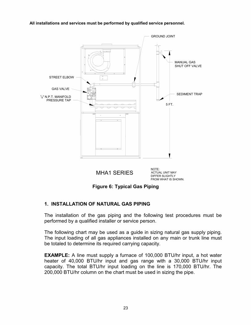
Figure 6: Typical Gas Piping 1. INSTALLATION OF NATURAL GAS PIPING
The installation of the gas piping and the following test procedures must be performed by a qualified installer or service person.
The following chart may be used as a guide in sizing natural gas supply piping. The input loading of all gas appliances installed on any main or trunk line must be totaled to determine its required carrying capacity.
EXAMPLE: A line must supply a furnace of 100,000 BTU/hr input, a hot water heater of 40,000 BTU/hr input and gas range with a 30,000 BTU/hr input capacity. The total BTU/hr input loading on the line is 170,000 BTU/hr. The 200,000 BTU/hr column on the chart must be used in sizing the pipe.
MHA1 SERIES
SEDIMENT TRAP
GROUND JOINT
STREET ELBOW
GAS VALVE
18" N.P.T. MANIFOLD
PRESSURE TAP5 FT.
MANUAL GAS SHUT OFF VALVE
NOTE:ACTUAL UNIT MAYDIFFER SLIGHTLY FROM WHAT IS SHOWN.

All installations and services must be performed by qualified service personnel.
24
TABLE 4: Steel Pipe Size for Natural Gas (IPS) Feet of Pipe From Meter to Burner Burner
Firing Rate, BTU/Hr 10 20 30 40 50
50,000 1/2 1/2 3/4 3/4 3/4 100,000 3/4 3/4 3/4 3/4 1 150,000 3/4 1 1 1 1-1/4 200,000 1 1 1-1/4 1-1/4 1-1/4 250,000 1 1 1-1/4 1-1/4 1-1/4 300,000 1 1 1-1/4 1-1/4 1-1/4
All black pipe sizes shown are nominal iron pipe sizes.
Use black iron steel pipe and malleable iron fittings for natural gas service lines. Provide rigid supports for the pipe. If the pipe size must be reduced, use reducing couplings when possible. Avoid the use of reducing bushings. Remove all burrs and inspect the pipe for dirt or other foreign material prior to connecting.
Maximum supply pressure for natural gas is 14.0 in. W.C. and minimum supply for purpose of input adjustment is 4.5 in. W.C.
2. INSTALLATION OF PROPANE GAS PIPING
:
• Copper and brass tubing and fittings (except tin lined) shall not be used if the gas contains more than a trace (0.3 grains per 100 cubic ft.) of hydrogen sulfide gas. Check with your gas supplier.
Maximum supply pressure for propane gas is 14.0 in. W.C. and the minimum supply for purpose of input adjustment is 11.0 in. W.C.
Experience has proven that the pressure drop in the gas line running from the outside propane gas tank to the gas appliances in a home is the most frequent cause of equipment malfunctions. A single pressure regulator, located at the tank, will not reliably regulate the high tank pressures (up to 200 PSIG.) down to 11.0 in. W.C. Varying pressures will occur at the appliances as outside temperatures and usage demands vary. Two-stage regulation is the only effective method of controlling gas pressure (refer Figure 7).
All installations and services must be performed by qualified service personnel.
25
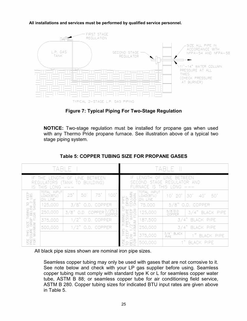
Figure 7: Typical Piping For Two-Stage Regulation
NOTICE: Two-stage regulation must be installed for propane gas when used with any Thermo Pride propane furnace. See illustration above of a typical two stage piping system.
Table 5: COPPER TUBING SIZE FOR PROPANE GASES
All black pipe sizes shown are nominal iron pipe sizes.
Seamless copper tubing may only be used with gases that are not corrosive to it. See note below and check with your LP gas supplier before using. Seamless copper tubing must comply with standard type K or L for seamless copper water tube, ASTM B 88; or seamless copper tube for air conditioning field service, ASTM B 280. Copper tubing sizes for indicated BTU input rates are given above in Table 5.

All installations and services must be performed by qualified service personnel.
26
M. Electrical
1. Wiring
: The furnace must be grounded in accordance with local codes or in the absence of local codes with the National Electrical Code, ANSI/NFPA 70-2002, or latest edition.
All wiring shall be performed by a qualified electrician or service person. The wiring must comply with local codes, the instructions in this manual, and in the absence of codes with the National Electrical Code, ANSI/NFPA-70, or latest edition.
Follow these guidelines to complete the wiring portion of the installations. A separate power supply circuit with over current protection and a disconnect switch must be provided. The minimum fuse or circuit breaker size is 15 amp. All electrical components and junction boxes shall be installed in such that they are protected from water. All MHA1/MDA1 series furnaces are supplied with a switch box to be mounted on the outside surface of the right or left side casing. A strain relief bushing is provided for support of the supply wire harness. Make the 115 volt supply connection in this junction box. A green screw is provided in order to connect the power supply ground wire. A disconnect switch can be field mounted on the 2x4 box provided. If not, the disconnect switch must be located reasonably close to and within sight of the furnace. NOTICE: The hot surface igniter and operation of this furnace depends on correct polarity. The hot leg of the supply circuit must be connected to the black line lead and the common leg to the white line lead in the field mounted junction box. The hot leg must be connected through the disconnect switch in all cases to prevent the hazard of electrical shock when servicing.
2. Field Wiring and Replacing Wiring
Field wiring between the furnace and devices not attached to the furnace shall conform to the temperature limitation for Type T wire [63°F (35°C) rise] when installed with the manufacturers instructions. If any of the original factory supplied furnace wiring is replaced, or a separate device other than the thermostat is wired internal to the unit, 105°C temperature rated thermoplastic insulated wire or equivalent wire must be used.

All installations and services must be performed by qualified service personnel.
27
3. Electronic Air Cleaner and Humidifier Connections
The ignition module on this furnace has designated terminals to control the operation of an electronic air cleaner and/or humidifier. These terminals provide line voltage for the control of these accessories (See Figure 8).
NOTICE: It is important to confirm that the operating voltage of the humidifier or EAC being installed matches the output of this control. If not, a field supplied relay or transformer may be necessary to provide the proper control and supply voltage for the accessory being installed. See the manufacturers instructions for the humidifier or EAC for additional requirements.
4. Room Thermostat
A room thermostat is not furnished with this furnace. However, a thermostat is required to properly operate the furnace control system. The room thermostat should be located in the natural circulating path of the room air. The thermostat should not be placed where exposed to cold air infiltration, i.e. drafts from outside openings such as windows and doors, or where exposed to air currents from supply or return air registers, or such that natural circulation of air is blocked, such as behind doors, in shelves, or in corners. It should always be located on an interior wall. In addition, the room thermostat should not be exposed to heat from a nearby fireplace, electrical appliances, lamps, rays from the sun, or mounted directly on a wall containing warm air ducts, a chimney, or a gas vent. These sources of heat could adversely affect the operation of the thermostat, preventing it from properly controlling the room temperature. Generally, a room thermostat should be set at the lowest temperature that is comfortable to the building occupants. This will result in the lowest cost to heat the building.
Proper control of the indoor temperature can only be achieved if the thermostat is calibrated to the heating and/or cooling cycle. A vital consideration of this calibration is related to the thermostat heat anticipator.
The proper thermostat heat anticipator setting is 0.8 AMPS for furnace operation only. To increase length of the heating cycles, increase setting of heat scale; to decrease length of cycle, decrease setting of heat scale.
Anticipators for the heating operation are of two types, pre-set and adjustable. Those that are pre-set will not have an adjustment scale and are generally marked accordingly.

All installations and services must be performed by qualified service personnel.
28
Anticipators for the cooling operation are generally pre-set by the thermostat manufacturer and require no adjustment.
5. Blower Motor Speed Wiring :
• TURN OFF THE ELECTRICAL POWER to the furnace before attempting to change blower speed wiring.
The blower motor is factory wired to the ignition control with standard heating and cooling speeds pre-selected. When changing motor speeds, simply switch the wire from the needed speed to either the heating or cooling terminal as applicable on the module to obtain the desired airflow. The wires for the unused speeds should then be reconnected to the module in the “park” positions.
Figure 8: Blower and Control Panel
The option switches on the W/R integrated control are used to determine the length of the heat delay-to-fan-on and delay –to-fan-off periods. The following tables show the time periods that will result from the various switch positions.
SPEEDS
PARK TERMINALSFOR UNUSED
23
41
ON
GREEN
120v
24v
GREEN CAPACITOR
TERMINAL HEATING SPEED
TERMINAL COOLING SPEEDTRANSFORMER
NOTE:MHA1-50,75,100,125MDA1-50,100USE LOW SPEED FOR HEATING
MDA1-75,125 USE MED-LOW SPEED FOR HEATING
MHA/MDA1-50 HAS A 3 SPEED MOTOR
HIGH SPEED (BLACK)
LOW SPEED (RED)
MED-LOW SPEED (BLUE)
MED-HIGH SPEED (YELLOW)
COMMON (WHITE)
OPTIONAL FAN DELAY SWITCHES
EACHUMIDIFIER
EAC - COMMON
HUMIDIFIER - COMMON

All installations and services must be performed by qualified service personnel.
29
Table 6: Blower delay settings for heating cycles
To delay fan turn-on by:
Set Switch #1 #2
15 sec. 30 sec. *45 sec. 60 sec,
Off Off Off On On Off On On
To delay fan turn-off by:
Set Switch
#3 #4 60 sec. 90 sec.
120 sec. *180 sec.
On On Off On On Off Off Off
*Factory settings for optimal performance
III. Initial Operation of the Furnace:
A. Initial Startup:
:
• Turn off power to furnace. Before the gas piping system is placed into service, it must have been leak tested by a qualified heating contractor. (Refer to the General Gas Piping Requirements section of this manual regarding the installation and leak testing of gas piping).
• For initial start-up of the appliance after installation, it may be
necessary to purge the air out of the gas line. A qualified heating contractor should do this. If excessive gas escapes when purging the gas supply at a pipe union joint, allow the gas to disperse for at least 15 minutes before attempting to start the appliance. LP gases are especially dangerous because the specific gravity of LP gases allows them to accumulate at ground level at possibly explosive concentrations.
Review the following items before the initial startup. It may be helpful to review the Sequence of Operations in Appendix B of this manual, also. a. Check all wiring for loose connections and proper hook-up. Refer to the
connection diagram.

All installations and services must be performed by qualified service personnel.
30
b. Leak test all field gas piping connections.
c. Check the tubing to the pressure switch to make sure it is snug and completely seated on the pressure tap.
d. Check to see that the vent terminal is correctly installed and the terminal
openings are clear and free from blockage.
e. Make sure the air filter is in place and relatively clean of dirt and debris.
f. Make sure the thermostat is set in the heating mode of operation.
For Your Safety Read Before Operating:
: If you do not follow these instructions exactly, a fire or explosion may result causing property damage, personal injury or loss of life.
This appliance does not have a pilot light. It is equipped with a hot surface igniter that automatically lights the burner. Do not attempt to light the burner by hand. BEFORE OPERATING smell all around the appliance area for gas. Be sure to smell next to the ground because some gas is heavier than air and will settle on the ground.
WHAT TO DO IF YOU SMELL GAS
• Do not try to light any appliance. • Do not touch any electric switch; do not use any phone in your
building. • Immediately call your gas supplier from a neighbor’s phone. Follow
the gas supplier’s instructions. • If you cannot reach your gas supplier, call the fire department.
Use only your hand to operate the gas control valve knob or, if equipped, the gas control valve switch. Never use tools. If the knob or lever will not move, don’t try to repair it, call a qualified service technician. Forced or attempted repair may result in a fire or explosion. Do not use this appliance if any part has been under water. Immediately call a qualified service technician to inspect the appliance and to replace any part of the control system and any gas control that has been under water.
All installations and services must be performed by qualified service personnel.
31
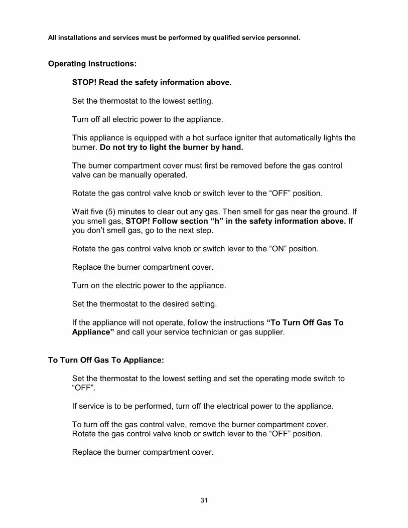
Operating Instructions:
STOP! Read the safety information above. Set the thermostat to the lowest setting. Turn off all electric power to the appliance. This appliance is equipped with a hot surface igniter that automatically lights the burner. Do not try to light the burner by hand. The burner compartment cover must first be removed before the gas control valve can be manually operated. Rotate the gas control valve knob or switch lever to the “OFF” position. Wait five (5) minutes to clear out any gas. Then smell for gas near the ground. If you smell gas, STOP! Follow section “h” in the safety information above. If you don’t smell gas, go to the next step. Rotate the gas control valve knob or switch lever to the “ON” position. Replace the burner compartment cover. Turn on the electric power to the appliance. Set the thermostat to the desired setting. If the appliance will not operate, follow the instructions “To Turn Off Gas To Appliance” and call your service technician or gas supplier.
To Turn Off Gas To Appliance:
Set the thermostat to the lowest setting and set the operating mode switch to “OFF”. If service is to be performed, turn off the electrical power to the appliance. To turn off the gas control valve, remove the burner compartment cover. Rotate the gas control valve knob or switch lever to the “OFF” position. Replace the burner compartment cover.

All installations and services must be performed by qualified service personnel.
32
B. Adjustment Of Heat Input Rate
The main burner gas orifices for this unit were selected based upon the following assumed characteristic values of the two fuel gases suitable for use with this appliance design:
a. For natural gas having a higher heating value of 1025 BTU per standard cubic foot and a specific gravity of 0.60, or
b. For commercial propane gas with a higher heating value of 2500 BTU per
standard cubic foot and a specific gravity of 1.53.
The appliance rating plate inside the burner compartment will specify for which gas the main burner orifices were selected. If the appliance is installed at an altitude that is more than 2,000 feet above sea level, it is mandatory that the input to the burner be reduced 4.0% for every 1,000 feet that it is above sea level. Example: A furnace installed at an elevation of 5,000 feet, its input must be reduced 20.0%. At 5000 ft, a total reduction of 5000 ft x 4% per 1000 ft or 20% is required. This equates to a reduced firing rate of 80,000 BTUH (100,000 BTUH x 0.80 = 80,000 BTUH) at an elevation of 5,000 feet. (If the furnace is installed at an elevation of 2,000 feet or less, no reduction in input rate is required.)
For high altitude installations, your local gas supplier may assist in determining the correct main burner orifice size for the elevation at which the appliance is installed. Our Engineering Department will gladly assist in sizing the orifice if the lower heating value, in BTU per cubic foot, the specific gravity of the fuel gas, and the altitude where the appliance will be installed are provided.
To check the input rate of the furnace, allow the unit to operate for 15 minutes and proceed as follows:
1. Contact your gas supplier and ask for the BTU content (higher heating value)
of one standard cubic foot of the fuel gas supplied to the appliance at the installation site. If the higher heating values are unavailable, it is reasonable to assume values of 1025 BTU/cu ft, for natural gas, or 2500 BTU/cu ft, for commercial propane gas.
2. With all other gas consuming appliances turned off and using a stopwatch,
clock the time required for the (small) dial on the gas meter to make one full revolution. The meter dial will indicate how many cubic feet pass through the meter during one revolution, usually one, two or five. The unit must have been in operation at least 15 minutes before clocking.

All installations and services must be performed by qualified service personnel.
33
3. The following formula may be used to calculate the heat input rate for the appliance:
Gas heating value x Amount of gas consumed = Heat input rate, or Amount of time required to consume the gas
BTU/cu ft x Number of cu ft x 3600 seconds = Input rate (BTU/hr). Seconds for one revolution x 1 hour
In cases where a gas meter is not installed on the fuel gas supply line, the input rate can be assumed to be approximately correct if the burner manifold pressure is the same as that shown on the rating label. Make sure the gas supply pressure at the appliance falls within the allowable range for the type of fuel gas. See table 8. The pressure to the furnace must be checked while the burner, and any other gas appliances, on the same supply system are operating. Measure the pressure using a pressure gauge, or manometer, at the 1/8 in. NPT plugged tap on the inlet side of the appliance gas control valve, shown in the General Gas Piping Requirements section of this manual. An Allen wrench is normally required to remove the plug from the valve. Make sure the fuel gas is shut off before removing this plug and installing a pressure test gage.
Table 8: Allowable Gas Pressures for All MHA1/MDA1 Models
Type of Fuel Gas
Range of Supply
Pressure (in. W.G.)
Manifold Pressure (in. W.G.)
Natural 14.0 - 4.5 3.5 (± .3)
Propane 14.0 - 11.0 10.0 (±. 3)
This appliance is equipped with multiple, identical, fixed, main burner orifices sized for the fuel gas and manifold pressure shown on the rating label. The input rate can only be increased, or decreased, by adjusting the manifold pressure. To adjust the manifold gas pressure to the main burners:
a. With the gas shutoff, remove the 1/8 in. NPT threaded pipe plug located on the front side of the main burner gas manifold. Use a U-tube manometer or pressure gage, capable of measuring pressure in inches of water column, to measure the gas pressure at this point.
All installations and services must be performed by qualified service personnel.
34
b. Turn on the fuel gas and cause the appliance to activate the heating section by answering a “call for heat”.
c. Allow the heating section to operate for 15 minutes.
d. Note the manifold gas pressure.
e. To adjust the pressure, remove the brass screw from the regulator on the
outlet side of the gas control valve. Using a common screwdriver, increase the manifold pressure by turning the screw inward (clockwise), or decrease it by turning the screw outward (counterclockwise). Adjustments to the listed pressure must not exceed 0.3 in. W.G. A 0.3 in. W.G. adjustment will change the input approximately 4.0%.
f. Measure the heat input rate by counting the number of seconds required
for the appliance to consume a specified quantity of gas. Refer to the preceding procedure to calculate the heat-input rate.
g. If required, repeat the manifold pressure adjustment again. Repeat the
input rate measurement.
h. When the input rate adjustment has been completed, shut off the fuel gas to the appliance. Remove the pressure gage. Reinstall the manifold pipe plug using a thread compound resistant to the action of LP gases. Replace the regulator screw (cap) in the gas valve.
If an input rate within the allowable range cannot be obtained with the present orifice over the range of manifold pressures given, make sure the gas supply pressure is within the specified range. If the supply pressure is less than required, the upstream supply pressure regulator may have to be adjusted to increase the pressure. If increasing the gas supply pressure fails to provide adequate gas pressure at the unit, the supply piping may have to be modified to reduce pressure drop.
C. Burner Adjustment
There are no manual adjustments to the main burners. With the burner compartment door removed, the flames can be observed. Natural gas flames should be relatively short in length, have well defined shapes, and are bright light to deep blue in color, refer to Figure 10.
NOTICE: For appliance operation with propane gas, it is not unusual to observe mostly blue flames having yellow or yellow-orange tips.

All installations and services must be performed by qualified service personnel.
35
Figure 10: Typical Observation of Main Burner Flames
If long, rather poorly defined, mostly yellow in color, and nearly opaque burner flames are observed, this is an indication the quality of combustion is poor. (Under adverse conditions, black smoke and some sooting may be noticeable as well.) Some of the causes of poor combustion are, too high an input rate (“over-firing”), too little or a contaminated supply of combustion air, or a partially blocked heat exchanger or vent terminal. Should any of these conditions occur, they must be corrected immediately. Call your qualified heating contractor for assistance.
D. Setting Supply Air Temperature Rise All MHA1/MDA1models are designed and wired at the factory for a blower speed during heating that should result in an approximate temperature rise of 70°F. The temperature rise through the heating section, for any given blower speed may vary depending on a number of factors. A few of these factors are, changes in the actual resistance of the duct system to airflow at any time, de-rating of the appliance due to elevation, fouling of the heat exchanger surfaces, and changes in the fuel gas heating value. In general, a lower temperature rise through the heating section will result in higher heating efficiency.
Temperature rise = supply air temperature - return air temperature. After 15 to 20 minutes of continuous operation, the temperature rise through the furnace must fall within a range of 55° to 85° F. If the outlet or supply duct temperature is too high, check to make sure the return air filter is clean, the return air registers are free from obstruction, the outlet registers are properly adjusted and clear, and the supply and return air ducts are open. The circulating air blower is not moving enough air if the supply air temperature is still too high. Before proceeding further, turn off the power supply to the appliance and remove the blower access door. The speed of the blower must be increased by changing the speed tap from the motor to the next higher tap, refer to Figure 8.

All installations and services must be performed by qualified service personnel.
36
E. Checkout Procedure
Before any system of gas piping is finally put into service, it shall be carefully tested to assure that it is “gas-tight”, as indicated in the General Gas Piping Requirements section of this manual. NOTICE: All controls on the unit should be checked for proper functioning prior to the qualified service personnel leaving the job site. Specifically the following should be checked:
1. With heating system in normal heating operation, check to make certain blower will start and stop automatically under control of integrated furnace control.
2. Check safety limit control as follows:
a. Shut off incoming power.
b. Block return air opening or disconnect blower motor leads.
c. Restore power to appliance.
d. In the heating mode, set the thermostat above room temperature
producing “a call for heat”.
e. When high air temperatures are reached within the furnace, the high limit control should act to shutdown the main burners.
f. Shut off the electrical power.
IMPORTANT: Remove blockage or reconnect blower motor and restore power.
3. Make certain the thermostat will automatically start and stop the appliance.
4. Block the vent terminal outlet gradually with a flat piece of metal, until the
pressure switch functions shutting off the main burners.
IMPORTANT: Remove flue blockage when done.
NOTICE: Heat exchanger oil will burn off on initial firing creating an unpleasant odor. To prevent this odor from occurring more than once, it is suggested the furnace be allowed to run for 30 minutes, or until odor has dissipated.

All installations and services must be performed by qualified service personnel.
37
IV. Troubleshooting
NOTICE: BEFORE TROUBLESHOOTING, FAMILIARIZE YOURSELF WITH THE START UP AND CHECKOUT PROCEDURE.
ALL INSTALLATION AND SERVICES MUST BE PERFORMED BY QUALIFIED HEATING CONTRACTORS. To assist you in troubleshooting this furnace, it is equipped with an integrated ignition control with diagnostics. These diagnostics evaluate what control system has experienced a failure and activate a flashing light on the control in different sequences to help pinpoint the failure which has occurred. Also provided in appendix C is a troubleshooting flow chart located in the back of this manual.
IMPORTANT: For your convenience, Thermo Products has installed a sight glass in the blower door of this furnace. The number of flashes in groups should be observed through this sight glass and recorded before turning off power to the furnace. Otherwise power to the furnace will be interrupted upon or removing the blower turning off power or removing the necessary to restart the furnace and have the failure occur again. DIAGNOSTIC FEATURES The 50A65 control used on this furnace continuously monitors its operation and the operation of the system. If a failure occurs, the LED light on the control will failure code. If the failure is internal to the control, the light will stay on continuously. In this case, the entire control should be replaced, as the control is not field-repairable. If the sensed failure is in the system (external to the control), the LED will flash in the following flash-pause sequences to indicate failure status (each flash will last approximately 0.25 seconds and each pause will last approximately 2 seconds).
1 flash, then pause System lockout 2 flashes, then pause Pressure switch stuck closed 3 flashes, then pause Pressure switch stuck open 4 flashes, then pause Open high limit, aux. limit, or roll-out switch 6 flashes, then pause 115 Volt AC power reversed 7 flashes, then pause Low flame sense signal 8 flashes, then pause Check ignitor or improper grounding Continuous flashing Flame has been sensed when no flame should
(no pause) be present (no call for heat) The LED will also flash once at power-up.
All installations and services must be performed by qualified service personnel.
38
V. Dealer Maintenance
SAFETY DURING SERVICING AND INSPECTION
:
ELECTRICAL SHOCK, FIRE OR EXPLOSION HAZARD
• Failure to follow safety warnings exactly could result in dangerous operation, serious injury, death or property damage.
• Improper servicing could result in dangerous operation, serious injury, death or property damage.
• Before servicing, disconnect all electrical power to furnace. • When servicing controls, label all wires prior to disconnecting. Reconnect
wires correctly. • Verify proper operation after servicing.
Notice: Homeowner/user routine maintenance
Complete instructions for the homeowner including maintenance procedures, which must be performed by the homeowner/user, can be found in the "Users Information Manual."
The following maintenance procedures should be performed at the beginning of each heating season by a qualified heating contractor. Correct any deficiencies at once.
A. Electrical 1. Check all wiring for loose connections and any signs of damage or unusual
wear. 2. Check for correct voltage at the furnace when operating. 3. Check amp-draw on blower motor and inducer motor to assure they are not
exceeding nameplate amp rating. 4. Check for correct operation and proper settings (if manually adjustable) of all
controls. Shut off gas and disconnect power before continuing.
B. General Inspection
1.Inspect the heat exchanger for evidence of corrosion, pitting, warpage, deterioration, and carbon build-up. Also, look for loose gaskets in the flue pipe, burner box and accessible areas of the heat exchanger.

All installations and services must be performed by qualified service personnel.
39
2. Chimney/vent pipe - Vertically vented units - Remove flue pipe from inducer and inspect for restriction, loose joints, carbon build-up and condensation. Clean vent and chimney if necessary and replace or repair any degraded vent, vent connector or chimney damage found. For sidewall vented units refer to the manufacturer’s maintenance instructions for the sidewall venter. 3. Burners - If it appears that material is accumulating in the burner box the box and burners can be vacuumed. If necessary, the burners box assembly can be removed from the separator panel, by removing the screws behind the 1” holes near the top of the burner box, and the one screw in the flange under the burner box. 4. Inducer Blower Assembly - Inspect pressure switch tubing connections and inspect inducer blower/assembly for corrosion, warpage, deterioration and carbon build-up. If necessary, clean housing and blower wheel with a damp cloth. Vacuum to remove any lint or dust from motor assembly. The inducer gasket and the collector box gasket must be replaced if they show any sign of having been damaged. 5. Clean all furnace markings as necessary and verify that all are still legible. Any illegible or missing markings must be replaced. Replacements can be obtained by contacting Thermo Products.
Once all components are cleaned, they must be re-installed to their factory-produced state. Any seals or joints in the flue system, which have been removed or loosened, must be reconnected and sealed if necessary. Do this in accordance with the installation instructions. (Section II, J, of this manual for vertically vented units, or Section II, K, of this manual for sidewall vented units).
NOTICE: After cleaning the furnace, reference the burner adjustment section of this
manual. Check for operation, proper combustion and no gas leakage according to the procedure outlined in Section III, of this manual, Burner and Adjustment. Observe the burner flame illustrations and follow the adjustment procedures if proper flame(s) are not present.
C. House Air Blower
Check and clean the blower wheel, housing, and compartment with a vacuum. Check the motor nameplate and follow motor manufacturer instructions for lubrication, if required.
IMPORTANT: Some motors are permanently lubricated and should not be oiled. See motor nameplate for specific instructions.

All installations and services must be performed by qualified service personnel.
40
D. Return Air Filter
The Return Air Filter(s): Provided with this unit is a permanent type filter. This filter(s) should be inspected and when dirty, cleaned or replaced, if necessary to assure proper furnace operation. Follow the cleaning, removal and replacement procedure below.
Filter Maintenance Procedure: The filter rack will be located between the return air plenum and the return air opening of the furnace. See Figure 11 for MHA1/MDA1 series units. Slide dirty filter out of the filter rack. Clean the filter by vacuuming, rinsing with tap water, hosing or dipping in an ordinary detergent solution. After cleaning, replace the completely dry filter in the rack. If the filter has a mesh, the mesh side of the filter must be towards the furnace.
Figure 11: Filter Location FILTER REPLACEMENT
Should the filter used require replacement, see Table 2 in Section II, I, of this manual for minimum filter areas required for the different types of filters available to ensure an adequate replacement is selected.
MDA1 SERIES
MHA1 SERIES
BLOWERACCESSDOOR
FILTERS
TYPICAL FILTERLOCATION
FRONT DOOR
SUPPLY AIR
RETURNAIR
COMBUSTIBLEFLOOR BASE
SUPPLY AIR
RETURN AIR
All installations and services must be performed by qualified service personnel.
41
IMPORTANT: Remind homeowner of the importance of monthly filter inspections during operation to ensure maximum efficiency.
VI. Installers Instructions to User
After completing the installation, the installer shall inform and/or demonstrate to the homeowner:
1. The location of these instructions in the furnace and that these instructions and the users information manual must be kept along with instructions for any accessories in the plastic pouch on the inside of the furnace.
2. The location and use of the manual gas shut off valve and furnace electrical
disconnect switch. Instruct user to always shut off gas before shutting off electric power.
3. The sequence of operation of the furnace. 4. The correct operation and maintenance of the appliance as outlined in the users
information manual.
5. That failure to maintain and operate this furnace in accordance with these instructions could result in hazardous conditions, bodily injury, and property damage and may void the limited warranty on the furnace.
6. Review with and encourage the user to read the warnings and instructions outlined on the front cover and the Safety section of this manual and in the Users Information Manual.
7. Recommend to the user that a CO detector be installed in the living space with the use of any fossil fuel burning appliance. The CO Detector should be one that is design certified by a nationally recognized testing agency.
8. Recommend that the user have a qualified heating contractor inspect the furnace at the start of each heating season. Inform the user of the frequency of inspection required for each item in Section IV of the Users Manual.
9. Inform the user to maintain adequate clearances around air openings into the furnace and not to block or restrict the entrance of air into the furnace area or the furnace air opening.

All installations and services must be performed by qualified service personnel.
42
APPENDIX A: SOURCES FOR REFERENCE STANDARDS 1. Air Conditioning Contractors of America
1712 New Hampshire Avenue, NW Washington, D.C. 20009 (202) 483-9370
2. American Gas Association Distribution Center P.O. Box 79230 Baltimore, Maryland 21279-0230 (301) 617-7819
3. American National Standards Institute, Inc.
Attn: Customer Service 11 West 42nd Street New York, New York 10036 (212) 642-4900
4. American Society for Testing and Materials
100 Burr Harbor Drive West Conshohoken, Pennsylvania 19428-2959 (610) 832-9585
5. American Society of Heating, Refrigeration, and Air-Conditioning Engineers, Inc.
1791 Tullie Circle N.E.. Atlanta, Georgia 30329 (404) 636-8400
6. National Fire Protection Association
1 Batterymarch Park Quincy, Massachusetts 02269 (800) 344-3555

All installations and services must be performed by qualified service personnel.
43
APPENDIX B: SEQUENCE OF OPERATIONS A. Sequence of Operations for Heating System
Control System Action
Ignition control moduleenergized,draft inducer starts.
After ignitor warm-up, the automatic gas control valve
is energized to open.
Mode of Operation
Standby(At any time the gas
valve is not energized)
Start
Start trial for ignition
Continous safe operation check. Ifflame simulation condition present
or roll-out switch opens,systemenergizes inducer fan and circulatorblower at high speed until situation
correction occurs.
Thermostat calls for heat,contacts close
Pressure switch sensesadequate pressure,
contacts close.
On power interruption, systemshuts off, restarts when
power is restored.
If flame is not detected, thegas valve is de-energized,the ignitor is turned off and the ignition control module
goes into the "Retry" sequence.
Power is applied to the hotsurface ignitor. Ignitor warms-
up for 20 seconds.
Flame must be detectedwithin 4 seconds. If flame detected, the delay-to-fan-
on time begins (45 seconds)
The retry sequence provides a 60 second
wait before ignition retry.

All installations and services must be performed by qualified service personnel.
44
Control System Action
Main Burner Operation
Mode of Operation
Call for HeatSatisfied
End of Cycle
System Lockout
Repeated Trials for Ignition.
After delay-to-fan-on periodends, circulating air fan is
energized at heating speed.The (optional) electronic air cleaner and humidifier are
energized.
After the delay-to-fan-offperiod ends, the circulating
air fan and {optional) electronic air cleaner are
de-energized.
If ignition attempt is unsuccessful,one more retry will be made before
the ignition control module goes intosystem lockout.
If flame is detected,then lost,the ignition control module will
repeat the initial ignition sequencefor a total of four recycles. After
four unsuccessful recycle attempts,the control will go into system lockout.The ignition control module will reset
automatically in 60 minutes.
If system is in lockout, try to reset by interrupting the power
to the furnace at the disconnecting switch or interrupting the call for heat
at the thermostat. If this doesnot restart the system, refer to the troubleshooting section of
this manual.
When thermostat is satisfied,contacts open and the gas
valve is de-energized. Afterproof of flame loss, inducer and (optional) humidifier are
de-energized. The delay-to-fan-off period begins
(180 seconds)

All installations and services must be performed by qualified service personnel.
45
APPENDIX C: TROUBLESHOOTING FLOWCHARTS
A. Heating System
Set thermostat subbase to "HEAT".Does thermostat make contact?
Yes
Is room temperatureabove thermostat setting?
No
Is the transformer supplying24 VAC to the thermostat ?
Yes
No
Replace thermostat.
Yes
Are the thermostat wires connectedproperly?
Replace control transformer.
Correct wireconnections.
No
Is there 24 VAC across"TH" & "TR" terminals of the
ignition control module.
Turn thermostat settingabove room temp.
Is the inducerblower operating?
Yes Yes
Check for continuity& proper connections
No No
Yes
No
Yes
Check input power,controlsystem fuse,disconnecting
switch and fuses (if equipped).
Is the control transformerreceiving 120 VAC?
No
No

All installations and services must be performed by qualified service personnel.
46
Yes
Yes
Yes
Yes
Yes
After pre-purge,does thehot surface ignitor energize
and glow?
Yes
After hot surface ignitorwarm-up, does gas valve
open?
Yes
No
No
No
No
Check the ignition control modulediagnostic LED lamp. Reset themodule by interrupting power to
system for more than one second.If LED stays on continuously, replace
ignition control module.
No
Check wiring to draft inducer.If okay, replace inducer assembly.
Is there 120 VAC across draftinducer power terminals "IND"& "IND N" at the ignition control
module?
Check wiring to hot surfaceignitor. If okay, replace hotsurface ignitor assembly.
Check wiring to gas valve.If okay, Replace gas valve.
Check across "MV" terminalson ignition control module for 24VAC during the 4 second flame
proving period after ignitor warm-up. Is there 24 VAC?
Is there voltage present at the hot surface ignitor terminals
"IGN" & "IGN N" at the ignitioncontrol module?
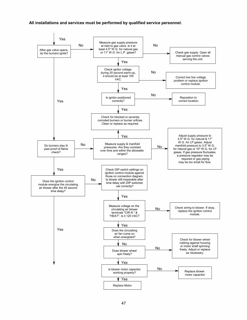
All installations and services must be performed by qualified service personnel.
47
Yes
After gas valve opens,do the burners ignite?
No
Check gas supply. Open allmanual gas control valves
serving the unit.
NoCorrect low line voltage
problem or replace ignitioncontrol module.
NoMeasure gas supply pressure
at inlet to gas valve. Is it atleast 4.5" W.G. for natural gas
or 11" W.G. for L.P. gases?
Yes
Is ignitor positionedcorrectly?
Yes
NoReposition to
correct location.
Yes
Yes
Check for blocked or severelycorroded burners or burner orifices.
Clean or replace as required.
Measure supply & manifoldpressures. Are they constant
over time and within the allowable ranges?
Yes
Yes
Measure voltage on the circulating air blowerterminals "CIR N " &
"HEAT". Is it 120 VAC?
YesDoes the circulating
air fan come onwhen energized?
Does blower wheelspin freely?
Yes
Is blower motor capacitorworking properly?
Yes
Replace Motor
No
NoReplace blower motor capacitor
No
Check for blower wheelrubbing against housingor motor shaft spinningfreely. Adjust or replace
as necessary.No
Check DIP switch settings onignition control module againstthose on connection diagram.Is blower still inoperable aftertime delay with DIP switches
set correctly?
Do burners stay litpast proof of flame
check?
No
Yes
Does the ignition controlmodule energize the circulatingair blower after the 45 second
time delay?
No
Yes
No
Check wiring to blower. If okay,replace the ignition control
module.
Adjust supply pressure to4.5" W.G. for natural & 11"W.G. for LP gases. Adjust
manifold pressure to 3.5" W.G.for natural gas or 10" W.G. for LPgases. If gas pressure fluctuates,
a pressure regulator may be required or gas piping
may be too small for flow.
Check ignitor voltage.during 20 second warm-up,
it should be at least 105VAC.

All installations and services must be performed by qualified service personnel.
48
Is LED light on ignitioncontrol module flashing?
Check all wiring forloose connections.
No
Troubleshooting Complete.
Yes
Does the circulating airblower turn off after
thermostat is satisfiedwithin 180 seconds?
Yes
Yes
Does burner shut offwhen thermostat is
satisfied?
Check DIP switch settingson ignition control module
against those on connectiondiagram. Reset if necessary.
No
Check for short in wire tothermostat. Replace
thermostat if necessary.
No
Yes
No
Yes
Does system run untilthermostat is satisfied?
If LED Light Flashes:
1 Flash, then pause............System lockout2 Flashes, then pause........Pressure switch stuck closed3 Flashes, then pause........Pressure switch stuck open4 Flashes, then pause........Open high limit, aux. limit, or roll-out switch6 Flashes, then pause........115 Volt AC power reversed7 Flashes, then pause........Low flame sense signal8 Flashes, then pause........Check ignitor or improper groundingContinuous flashing............Flame has been sensed when no flame (no pause) should be present (no call for heat)

All installations and services must be performed by qualified service personnel.
49
APPENDIX D: PARTS PACKAGE COMPONENTS
INSTALLATION PARTS PACKAGE MDA1/MHA1-50(S00S4426)
DESCRIPTION PART NUMBER QTY. WIRE NUT 300132 2 #8X1/2 TEK SCREWS 300208 2 for mounting 2X4 J-box #10-32X1/2 GND SCREW 300109 1 #10-32 HEX NUT 300110 1 3/16” DIA. STAR WASHER 300270 1 2X4 J- BOX 350024 1 2X4 J- BOX COVER 350020 1 GROUNDING INSTRUCTIONS MG-966 1 HEYCO SR 34-2 350016 1 HEYCO UB-875 350750 1
INSTALLATION PARTS PACKAGE MHA1/MDA1-75(S00S4427)/MDA1/MHA1-100 (S00S4428) / MDA1/MHA1-125
(S00S4429)
DESCRIPTION PART NUMBER QTY. WIRE NUT 300132 2 #8X1/2 TEK SCREWS 300208 2 for mounting 2X4 J-box #10-32X1/2 GND SCREW 300109 1 #10-32 HEX NUT 300110 1 3/16” DIA. STAR WASHER 300270 1 2X4 J- BOX 350024 1 2X4 J- BOX COVER 350020 1 GROUNDING INSTRUCTIONS MG-966 1 HEYCO SR 34-2 350016 1 HEYCO UB-875 350750 1 3” X 4” TAPERED TRANSITION 14310 1

All installations and services must be performed by qualified service personnel.
50
APPENDIX E: REPLACEMENT PARTS LIST - MHA1
120v
24v
34
21
ON

All installations and services must be performed by qualified service personnel.
51
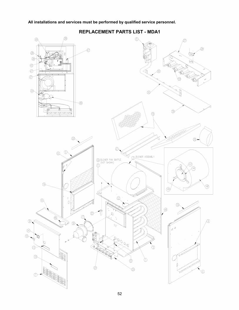
All installations and services must be performed by qualified service personnel.
52
REPLACEMENT PARTS LIST - MDA1

All installations and services must be performed by qualified service personnel.
53

All installations and services must be performed by qualified service personnel.
54
APPENDIX F: WIRING DIAGRAM

All installations and services must be performed by qualified service personnel.
55

All installations and services must be performed by qualified service personnel.
56
APPENDIX G: MID-EFFICENCY FURNACE SPECIFICATIONS MID-EFFICIENCY HIGHBOY GAS FURNACE SPECIFICATIONS5
Model NO. MHA1-50 MHA1-75 MHA1-100 MHA1-125 Heat input rate (BTUH) 50,000 75,000 100,000 125,000 Heating capacity (BTUH)1 40,000 59,000 79,000 99,000 Nominal temp. rise 70°F Heating fan speed LOW LOW LOW LOW Burner orifice size for nat. gas 0.0935” (#42) Burner orifice size for L.P. gas 0.0591” (1.5 mm) AFUE % 80.0 80.0 80.0 80.0 Height of casing 44-1/4” Width of casing 17” 17” 21” 24” Depth of casing 27 ½” Warm air outlet2 15” x 18” 15” x 18” 19” x 18” 22” x 18” Return air inlet2 25” x 16” 25” x 16” 25” x 16” 25” x 16” Approx. shipping weight 131 LBS 143 LBS 170 LBS 186 LBS Dia. of flue (vertical vent) 3” 4” 4” 4” Dia. of flue (sidewall vent)3 3” 4” 4” 4” CFM @ .2” & .5” W.C. external static pressure .2” .5” .2” .5” .2” .5” .2’ .5”
@HI speed 950 830 1495 1335 1795 1560 2245 1970 @MH speed 860 740 1205 1125 1590 1410 1885 1710 @ML speed - - 920 865 1410 1290 1605 1510 @LO speed 580 440 750 700 1240 1160 1350 1300 Blower motor type & frame Permanent split capacitor, air over, 48 Y Blower motor nominal HP 1/5 1/3 1/2 3/4 Blower motor full load amps 3.25 6.0 8.0 11.0 Motor shaft diameter ½” Direction of rotation (shaft end) Clockwise No. of speeds 3 4 4 4 Run capacitor 10 mfd
370 VAC 10 mfd
370 VAC 10 mfd
370 VAC 15 mfd
440 VAC Blower size 10-7 R DD 10-9 R DD 10-9 R DD 10-9 R DD Size of filters (1) – 1” x 24 ¾” x
15 ¾” (1) – 1” x 24 ¾” x
15 ¾” (1) – 1” x 24 ¾” x
15 ¾” (1) – 1” x 24 ¾”
x 19 ¾” Largest recommended air conditioner4 2 Ton 3.5 Ton 4 Ton 5 Ton
Electrical power requirements 115 volts, 60 Hz., 1 phase Min. Fuse size 15 AMP 15 AMP 15 AMP 20 AMP
ACCESSORY ITEMS Filter Rack Flange dimensions2 AOPS 7547
24-1/2” X 15” AOPS 7547
24-1/2” X 15” AOPS 7547
24-1/2” X 15” AOPS 7375
24” X 19” NOTES:
1. BTU output based on annual fuel utilization efficiency rated by manufacturer. 2. On all outlet and inlet dimensions, the first dimension is width. 3. The MHA1/MDA1 furnaces are approved for sidewall venting using only an approved sidewall power venter. Refer to Side
Wall Venting section of the Installation and service manual provided with the furnace for additional information. 4. To permit largest recommended air conditioning (at .5 static pressure), selection of the highest motor speed is required. 5. All specifications are subject to change without notice.

All installations and services must be performed by qualified service personnel.
57
MID-EFFICIENCY COUNTERFLOW / HORIZONTAL GAS FURNACE SPECIFICATIONS5 Model NO. MDA1-50 MDA1-75 MDA1-100 MDA1-125 Heat input rate (BTUH) 50,000 75,000 100,000 125,000 Heating capacity (BTUH)1 40,000 60,000 81,000 101,000 Nominal temp. rise 70° F. Heating fan speed LOW MD LOW LOW MD LOW Burner orifice size for nat. gas 0.0935” (#42) Burner orifice size for L.P. gas 0.0591” (1.5 mm) AFUE % 81.0 80.0 81.0 81.0 Height of casing 44-1/4” Width of casing 17” 17” 17” 17” Depth of casing 27 ½” Warm air outlet2 15” x 18” 15” x 18” 19” x 18” 22” x 18” Return air inlet2 15” x 18” 15” x 18” 19” x 18” 22” x 18” Approx. shipping weight 131 LBS 143 LBS 170 LBS 186 LBS Dia. of flue (vertical vent) 3” 4” 4” 4” Dia. of flue (sidewall vent)3 3” 4” 4” 4” CFM @ .2” & .5” W.C. external static pressure .2” .5” .2” .5” .2” .5” .2’ .5”
@HI speed 900 730 1400 1220 1595 1370 2075 1790 @MH speed 835 680 1200 1075 1460 1260 1830 1605 @ML speed - - 926 850 1360 1170 1620 1430 @LO speed 580 425 765 700 1220 1075 1345 1265 Blower motor type & frame Permanent split capacitor, air over, 48 Y Blower motor nominal HP 1/5 1/3 1/2 3/4 Blower motor full load amps 3.25 6.0 8.0 11.0 Motor shaft diameter ½” Direction of rotation (shaft end) Clockwise No. of speeds 3 4 4 4 Run capacitor 10 mfd
370 VAC 10 mfd
370 VAC 10 mfd
370 VAC 15 mfd
440 VAC Blower size 10-9 R DD 10-9 R DD 10-10 R DD 10-10 R DD Size of filters (2) –1” x 17 ¾” x
11 ¾” (2) –1” x 17 ¾” x
11 ¾” (2) – 1” x 17 ¾” x
13 ¾” (2) – 1” x 17 ¾”
x 17 ¾” Largest recommended air conditioner4 2 Ton 3 Ton 3.5 Ton 4 Ton
Electrical power requirements 115 volts, 60 Hz., 1 phase Min. Fuse size 15 AMP 15 AMP 15 AMP 20 AMP
ACCESSORY ITEMS Combustible Floor Base 50DA-BASE 50DA-BASE 100CA-BASE 125CA-BASE Horizontal Plenum Angles AOPS4942 Vent Kit (top vent option) AOPS4941 NOTES:
1. BTU output based on annual fuel utilization efficiency rated by manufacturer. 2. On all outlet and inlet dimensions, the first dimension is width. 3. The MHA1/MDA1 furnaces are approved for sidewall venting using only an approved sidewall power venter. Refer to Side
Wall Venting section of the Installation and service manual provided with the furnace for additional information. 4. To permit largest recommended air conditioning (at .5 static pressure), selection of the highest motor speed is required. 5. All specifications are subject to change without notice.