Gasoline Engine Tune
21
MICROFICHE REFEWEPICE LIBRARY A project of Volunteers in Asia Gasoline Engine Tune-Up (publication 105Nj Published by: Consxer Information Center Available from: Superintendent of Documents Consumer Information Center P.O. Box 100 Pueblo, Colorado 81002 USA Reproduced by permission. Renroduction of this microfiche document in any form is subject to the same restrictions as those of the original document.
Transcript of Gasoline Engine Tune
MICROFICHE REFEWEPICE LIBRARY
A project of Volunteers in Asia
Gasoline Engine Tune-Up (publication 105Nj
Published by:
Consxer Information Center
Available from:
Superintendent of Documents Consumer Information Center P.O. Box 100 Pueblo, Colorado 81002 USA
Reproduced by permission.
Renroduction of this microfiche document in any form is subject to the same restrictions as those of the original document.

-------- _I , .I
, {Sk ),

(right) When your auto record book tells you It’s been 15,000 miles or one year since your car’s last tuneup, it’s time to grab a good workshop manual and bring your engine up to specifica- tions.
(below) Wear eye protection when checking the fluid level in the battery cells.
The air cleaner should be checked every year and replaced every other tuneup no mat- ter how good it looks.
Always disconnect the ground (negative, on most cars) first and reconnect it last.
Yau can see how the dirty air cleaner on the left would restrict air flow.
DRIVER

uning your vehicle is one of the best preventive mainte- nance steps you can take. Be-
sides avoiding costly breakdowns, tuneups prevent wasteful consump- tion of fuel as well as your dollars.
Studies have found that 42 out of every 100 vehicles show signs of im- proper engine maintenance and are wasting fuel. Yet the average tuneup improves fuel economy 11.7 percent. And, in some cases, 50 percent im- provements have resulted from such maintenance. In addition, an average tuneup will pay for itself in 7000 miles - 2500 miles if you do the work your- self.
Make sum the gas flow arrow is pointing in the right direction when replacing the fuel filter.
JUNE 1003
Instead of waiting for a noticeable drop in your mileage - rough idling, hesitation, dieseling, hard starting, stalling, surging, pingi g, misfire or lack of power - you should tune your car annually or every 15,000 miles if you drive more than that each year.
While there are no magic tricks or gadgets that are going to double your car’s miles per gallon, it is going to operate at its best when tuned proper- ly to the manufacturer’s specifica- tions. Thus the best way to maximize your car’s mileage and performance is to give it a thorough tuneup.
Because the key to a proper tuneup is setting the vehicle to the manufac- turer’s specifications, you’ll need a good workshop manual for your spe- cific vehicle. In addition to providing all the correct specifications, such manuals furnish information and pro- cedures for routine maintenance and servicing as well as diagnostic and repair procedures to follow when trouble occurs. As procedures do vary from vehicle to vehicle, you’ll only be able to use the Backyard Mechanic as a general guide.
Be sure to read the tuneup section of the manual from start to finish be- fore tackling the job. You’ll not only get a good idea about what’s in- volved, as well as what parts and tools will be required, but you also may find very helpful hints buried in the fine print. Sometimes there’s even a hint about step 11 written in step 37.
Furthermore, after reading the tuneup section you may decide the work is beyond your skills and have a professional do the job for you. You’ll still be ahead of the game be- cause you’11 have a better under- standing of what has to bz done and how.
After reviewing the manual, the first step in a tuneup is a quick inspec- tion of the basic components that af- fect reliability and performance.
First, after removing any jewelry, pop the battery filler caps off and che:ck the fluid level. Don’t look di- rectly into the cells without wearing some sort of eye protection. If the fluid level is below the fill line or doesn’t cover the tops of the plates in all the cells, bring it up with distilled water. Tap water is okay in emergen- cies only.
Of course you can’t check the fluid level in a maintenance-free battery, but there are some checks that can be performed, so read your owner’s manual to find out what they are.
Next make sure the battery case and terminals are clean. When re- moving the battery cables, be sure to disconnect the ground cable first (the cable that runs to the frame or engine - usually negative). When recon- necting the cables, do the ground last.
Terminal and connection corro- sion (white fluffy deposits that are brittle to the touch) should be cleaned cff with steel wool, a wire brush or a special cleaning tool until the metal is bright. A dirty battery case can be washed with a baking soda and water solution and rinsed with clean water. Be careful not to get any of the soda solution in the cells.
Trace the positive czble to make sure all e!ectrical connections are tight, especially at Lne starter. The cables should be replaced every four years or 50,000 miles as part of a pre- ventive maintenance program.
Put grease or petroleum jelly around the base of the terminals - not on the terminals - before recon- necting the cables. After reconnect- ing the cables, also coat the top of the cleaned battery terminals. The coat-
continued
1

c-: - >= z t E ,i
7 SC- -7 1 r. L
3 i 2 J 5-e 7 ?-z 7 .7 ; 22 = r_ Ef? /F-’
-i -. r r; - - , = ‘, ” 27 f z c 1; /
#r 3 e =. / - - Err; c = c 4 c-
. . - , z 5= s- r. - =. x r;- T’ c - 3
-i i-5;
- =: .. =f “, 7--J,, r, - 3 -- 7 5 ,r* =
‘Hr.. -
-- 7 4 L 5 5 ;r y ,a? (P 72 ,s
cl Jf! zz 2 y> T ,T ;ic P2 LU ‘5 c ;a ?” : 5 r ^- 3? r, 2 <;
-. - 23 Eg 2s ;e ::4 ‘2 ;;1 9-a 3 L5 25 ss CT - ‘; z- nr 25 q ,’ Lo 3 ml

Although the EGR valve is often hard to lo- cate on the intake manifold, it must be checked at every tuneup.
Another hard-P-see item is the flapper in the air cleaner snorkel. This one is closed, as it should be when the engine is cold.
Plug wires are removed by grabbing the boot (and only the boot), twisting until it “pops” and then pulling them off the spark plug.
California vehicles). it may have none.
The PCV valve is usually pushed into one of the rocker arm or valve covers on the engine with a hose con- necting it to either the carburetor or intake manifold. The simplest way to check its operation is to put a sheet of paper over the oil filler neck with the engine running. If the paper is pulled in by the suction, the system is oper- ating.
Another way to check PCV valve operation is to remove the valve from its rubber grommet seat and press your finger over its open end. Engine speed should drop at least 40 rpm if the valve is functioning properly.
Regardless of how good the valve acts, replace it every three years or 40,000 miles.
Also check the rubber grommet in the cover for damage. If it is faulty, replace it with a new one. Also re- place it when installing a new PCV valve. When reinstalling the PCV
JUHE lM3
valve make sure that it is properly seated and/or clamped in its hose. the end pushed securely into its rocker cover seat.
On nearly all cars there is also a PCV filter located; inside the air cleaner housing. It should be in- spected and replaced when the PCV valve is.
The EGR valve is normally lo- cated on the intake manifold, nea; the carburetor. With the engine warmed up and running at slow idle, discon- nect the hose leading to the EG R and attach a hand vacuum pump to the valve. Pump the tool until it reads at least four inches of mercury. The en- gine should either start running rough and missing or stop. If it doesn’t, the EGR valve needs servicing or, in most cases, replacing.
The complicated !ooking fuel evaporation system is really one of the simplest and most trouble-free portions of the emissions network. You can usually tell if it isn’t working
right because there’ll be a strong odor of gasoline present.
At tuneup time you’ll want to check the hoses for cracks and secure connections, and test the purge valve(s). As these tests vary from ve- hicle to vehicle, consult your car’s workshop manual for details.
Basically you are going to discon- nect and plug the purge valve’s vac- uum source and make sure that air doesn’t pass through the valve. Then reconnect (and unplug) the vacuum line and ensure that air does go through the valve when the engine is running between 1,500 ai!d 2,000.
The fuel evaporation system canis- ter should be inspected for charcoal leakage and loose internal parts. Tap the charcoal canister and if you hear any rattling noise, replace it.
Most American-built cars have canisters with replaceable filters in the base. While one manufacturer suggests relllacing the filter every 15,000 miles and the canister every
continued
3

the backyard mechanic continued
Inspact inside the rubber plug wire boot for corrosion.
30,000, another says the filter should last 30,000, and the other says no ser- vice is needed. Replacing the filter every other tuneup should be ade- quate .
Older model cars will have a mani- fold heat control valve located on the exhaust pipe or crossover near the exhaust manifold. When the engine is cold - and turned off - see if you can move the valve. If you can, give both ends of the valve’s shaft a shot of manifold heat control valve sol- vent. If it’s stuck, try tapping it light- ly with a plastic mallet to free it up. Once it is free moving, be sure to lubricate it.
Most cars built since 1971 and many older than that have thermo- static air control systems instead of a manifold heat control valve (a few still use both). Vehicles with ther- mostatically-controlled air cleaners will have a hot air tube or pipe run- ning from the exhaust manifold to the air cleaner intake. Inside the long snorkel air cleaner intake, about where the hot air tube or pipe con- nects to it, is a vacuum flapper door.
The best way to test this system is with both the engine and outside air cold. Start the engine and keep your
4
eye on the flapper door: It should close over the snorkel. As the engine warms up to operating temperature, the flapper should open to allow cooler air into the air cleaner. This could take a minute. or 10 to 15 min- utes.
If the valve doesn’t open by the time the engine has reached 100 to 120 degrees Fahrenheit some repairs are required.
All the emissions system and vac- uum hoses should also be inspected
for cracking, loose clamps and leak- ing. Trace the full length of each hose - removing the air cleaner if neces- sary - squeezing it to check for cracks and look for swelling, dis- coloration and leaks.
If there are a lot of miles on the vehicle and one or more of the hoses are suspect, it’s agood idea to replace them all. Measure the length and in- side diameter of each hose, obtaining and cutting each replacement to size. Replace each hose one at a time to avoid the possibility of confusion.
Spark plug wires are probably among the most neglected tuneup items next to the spark plugs, and air and fuel filters. As a result they can and do cause plenty of problems.
Inspect the wires one at a time to avoid mixing up their order. Begin by disconnecting the wire from the spark plug. A special removal tool can be very helpful for this since it prevents damage to the wire. Without the tool you must grab the wire’s rubber boot, twist slightly until it “pops” and then pull the wire free. Be sure that you are pulling on the boot, not the wire.
inspect inside the boot for a white crusty powder which is a sign of cor- rosion. Don’t mistake the white con- ductive grease currently being used for corrosion. While it may be possi- ble to clean the corrosion from the boot, it would be better to replace the wire.
Push the boot and wire back onto the spark piug. It should fit tightly. If it doesn’t, pull it back off and use a
In8pOCt each wire for bums, cracks and other damage while wiping it clean.

pair of pliers to carefully crimp the metal connector inside the boot until the fit is snug.
Now use a clean rag and remove all the dirt and grease from the full length of the wire. As you’re doing this, check for burns, cracks or other damage. Bend the wire in several places to ensure that the conductive core inside has not hardened. But remember the core is brittle and will not tolerate rough handling.
Disconnect the wire at the distribu- tor (again, pulling and twisting the rubber boot only). Check this end for corrosion and a tight fit also. Now check the remaining spark plug wires in the same way, making sure they are all securely fastened to the spark plug and distributor, as weil as clean and in good condition.
Choclr all vacuum lines for cracks and other signs of leaks. This one will have io be re- placed.
A visual check of the wires can also be made in a darkened garage. Make sure the garage is well ventilated be- fore starting the engine and looking at each plug wire. if there is a break or fault in the wire, you will see a small spark or arcing at the bad area.
You can also run a continuity test on each wire with a voltmeter and a. 12-volt battery. Connect the wit being tested in series with the voltme- ter. If the voltage ranges from 7.8 to 12.4 volts, the wire is good. If the voltage is less than 7.8 volts, replace the wire.
Keep in mind that if one wire is bad, the others wili probably fail soon, too. Regardless of how good they seem, you should replace the wires every other tuneup.
The best wajr to install new wires is to buy a replacement kit designed specially for your car’s engine. These kits come with wires pre-cut to the proper length and with the rubber boots already installed. The only trick is to replace one wire at a time so that you keep the proper firing order.
continued
Safety First Set the parking brake and
chock the wheels. Put man- ual transmission in neutral, automatic in park.
Operate the engine in well-ventilated areas only.
Keep hands, hair, loose clothing and test leads well away from moving engine parts.
Don’t touch hot exhaust manifolds, radiators, spark plugs and coil terminals.
Never look into a carbure- tor while the engine is being cranked or is running.
Don’t smoke, use open flame (torch) or allow sparks to occur near the carburetor,
fuel line, fuel filter, fuel pump9 spilled gasoline, cleaning solver?ts, other flammables or a charging battery.
Be very cautious using anything electrical within 18 inches of the flaor.
Gasoline is NOT a clean- ing solvent.
Keep a fire extinguisher rated for gasoline and elec- trical fires handy.
Use the proper tool of the proper size and fit for every job.
Wear safety goggles when drilling, grinding, or using a chisel.
Uniform of tltm day - Wearing coveralls to protect your clothing and yourself from dirt and grease is a very good idea. Now, tie up your long hair and remove any rings, watches, bracelets and other jewelry you’re wearing. lf that ring is so sentimental that you won’t (or can’t) take it off, cover it with duct tape. You might wan1 to wrap those loose legs with tape to keep ihem out of harm’s way, too.
JUNE lW3 b

the backyard mechaaic continued
At every tuneup, if not more fre- quently, a can of carburetor combus- rion chamber cleaner should be sprayed down the carb’s throat ac- cording to the can’s instructions. The outside of the carburetor - especial- ly the choke plate and linkages - should also be sprayed clean with carburetor cleaner or choke solvent.
Move the throttle linkage back and forth once or twice. If gasoline doesn’t shoot into the carburetor, check the fuel system for a malfunc- tion before continuing the tuneup.
With the engine cold, start it and make sure that the choke closes and then fully opens as the engine warms up. If it doesn’t, check its operation following your workshop manual.
After checking other basics such as drive belts, radiator .hoses, coolant level, etc., you’ll be ready to get into the actual tuneup in next month’s DRIVER. @
Clean thm inside of the carburetor according to the instructions of the carburetor combustion chamber cleaner can.
The outmldo of the carburetor must also be cleaned and the linkage lubricated.
Raw fuel should shoot into the carburetor when the throttle is moved back and forth.

A vacuum gauge gives dn lnslant engine analysis A healthy engine pulls a steady 17 to 22 Inches of vacuum
If you don’t have compressed air fu, blowing dlrl out 01 the spark pltig ports. use a straw and your lungs
Anytime you are going to crank the engine but vou don 1 want 11 to star7 the COII hqLPnslon cable m!lst be removed frnm the colt or dlstrlbu- for and qrounried
JULY 1983
(left and above) A spark plug wrench makes spark plug removal easier. However, If you don’t have one you can put a sectron of garden hose over the Insulator for easier removal once you ve loosened the plug
7

THE THREE=PAR+
2
Y our car is going to operate at its best when tuned properly
f 0 the manufacturer’s specifications. Therefore, the best way to maximize your car’s mileage and performance is to give it a thorough tuneup annually or every 15,000 miles if you drive more than that each year.
The average tuneup improves fuel economy 11.7 percent and will pay for itself in 7000 miles - 2500 if you do the work yourself. So instead of waiting for a noticeable drop in your mileage, rough idling, hesitation, die- seling, hard starting, stalling, surg- ing, pinging, misfire or lack of power, you should tune your car regularly as a preventive maintenance step.
In the first part (June 1983) of this three-part series the Backyard Mechanic inspected the battery, re- placed the air and fuel filters, checked the emissions control sys- tems, cleaned and examined the spark plug wires, and cleaned the carburetor. Also discussed in the first part of the series was the importance of having a good workshop manual for your specific vehicle as well as reading the entire tuneup section be- fore tackling the job.
In this month’s installment you are going to check the engine’s internal condition before beginning the actual tuneup. After all, tuning a malfunc- tioning engine is a waste of time and money and will do nothing to improve mileage, performance or emissions. The internal engine checks are done by testing vacuum and compressioT$
A $10 vacuum gauge can help you diagnose more than 30 different en- gine problems from sticking valves to poor rings, including bad carburetor adjustments and a leaky head gasket. Since specific engine $roblems affect manifold vacuum in certain ways, the gauge can be used to accurately diag- nose the condifion of an engine by
m
measuring the amount and condition of vacuum.
To provide this measure and condi- tion report, the vacuum gauge must be hooked up correctly. You can’t just pull any vacuum line and attach the instrument. Accurate, reliable readings can be obtained only from primary manifold vacuum sources.
On older vehicles with vacuum- operated windshield wipers, remove the wiper system vacuum hose at the intake manifold and attach the gauge hose. Many vehicles have a threaded plug in the intake manifold that can be removed and a special fitting installed to attach the gauge to. If there isn’t a manifold source to attach the gauge hose to, put a T-fitting in the vacuum line to the power brake unit or vac- uum assist on disk brake-equipped CarS.
For best results, always attach the gauge as close to the vacuum source as possible.
To check the engine’s vacuum, warm the engine up to operating tem- perature. At idle a healthy engine will give a steady, constant reading of 17 to 22 units (inches of Mercury), al- though some newer four- and six- cylinder models deliver acceptable performance as low as 15 points. Also, a slight flicker of the needle can be expected with high-performance engines. There is a drop of one inch for each 1,000 feet above sea level.
The engine that gives a steady vac- uum reading at idle, with the needle dropping toward zero and jumping back past 20 when the throttle is opened and closed quickly, is in good condition. Anything else can spell trouble.
For example, if the reading is fairly steady but two inches lower than normal there can be several prob- lems. One might be that the engine isn’t fully warmed up. Another could be that the engine oil is too heavy.
Other problems that cause this lower than normal steady reading include late valve timing, late ignition timing or intake manifold leaks.
If the steady reading is three to four inches lower than normal, open and close the throttle rapidly. If the nee- dle sinks and then soars the piston rings are leaking.
Steady readings that are extremely low can be caused by a cracked or warped intake manifold, or a very bad carburetor to manifold gasket. Such readings can be as much as 15 units low.
If the needle alternately drops four to five points and then returns to normal you’ve got a sticking L&C(S). Should the point alternately fall more than five units before retqrning to normal you’re facing a burned valve(s).
continued
A ram&e strrter switch helps make quick work of doing compression checks.
DRMR

the backyard mechanic continued
Record the highest compresston reading from each cylinder and then compare them to be sure that they are within the specifications.
A box with holes punched into it makes an excellent spark plug holder. Although this box was made for eight-cylinder engines, it works equally well for four-cylinder models and can be used for sixes both straight andvee-design.
Examine the plugs at the firing end to learn how each cylinder has been performing during the past year or 15.000 miles.
A needle that fluctuates with a rhy- thm is telling you that there’s a prob- lem with only one cylinder. The prob- lem could be a fouled spark plug, burned valve seat, blown head gas- ket, cracked distributor cap, distribu- tor cap tracking or any number of things that affect only one cylinder.
A wavering, irregular needle tells you that the problem is affecting more than one cylinder. Again, there are a number of things that can cause this condition. They include: a poorly adjusted carburetor. a high float level, a distributor shaft or bushing, distributor advance control mecha- nism trouble, excessive spark timing advance or retard, unsynchronized dual ignition points, too wide a spark plug gap, or poorly seating intake valves.
To help you pinpoint what a needle that sweeps or wanders erratically through several inches of vacuum is trying to tell you, up the engine speed to about 2000 rpm.
If the pointer steadies, check the
JULY 1985
ignition system, timing and carbure- tor mixture adjustment at idle - all things you’ll be doing in part three ,f this basic tuneup next month. How- ever, you don’t want to overlook the possibility of the problem coming from worn valve guide stems.
Should the sweeps become even larger at 2000 rpm the problem may be weak or broken valve springs. However, if the sweeps are shorter but more rapid, the problem could be either sticky valves or an induction system leak.
A needle that vibrates excessively at all engine speeds is pointing toward a leaking head gasket.
If at a steady 2000 rpm the needle drops slowly toward zero there is an exhaust system restriction.
Should there be no wide sweeps in the amount of vacuum when you suddenly open and close the throttle, you could have an intake leak (gas- kets, valve seats, etc.)
Any time you suspect an external leak is causing a problem, squirt
some oil where you think the leak might be. Then check the vacuum reading again. If the oil temporarily seals the leak, the readings will im- prove.
For the compression test you must first remove all the spark plug wires one at a time. Be careful to label each so that it can be returned to its proper cylinder. One way to label the cables is with numbered tapes. Another labeling method is to mark numbers on clip-type clothespins and attach them to each wire.
If you don’t have a spark plug cable remover, grip the boot - and only the boot -by hand being careful not to bum yourself on nearby manifolds. Then twist the boot back and forth until it “pops” signaling that it’s lost its grip on the plug. Then pull the boot off the spark plug. Never pull on the cables.
Before removing the spark plugs, clean any dirt particles out of the ports. If you don’t have compressed air to do this with, blow the dirt out
0

A spark plug’s gap is correct if there is a slight drag on the proper size wire of the gauge.
To adjust the gap, use the notched adjuster on the gauge body to bend the curved side electrode slightly.
with a straw. Be sure to wear some kind of eye protection while doing this;.
Now you can remove the spark plugs. but be careful to keep them in order. A cardboard box with holes punched into it numbered according to engine position makes an excellent holder for the plugs.
Now remove the coil high-tension cable from the distributor and ground it to the engine block. Also block the throttle and choke wide open.
If you’re going to be using a remote starter switch on a General Motors vehicle having a High Energy Igni- tion (HEI) you’ve got different dis- connections to make. On V-6 and V-8 HEIs, disconnect the primary wire from the “Bat” terminal on the dis- tributor cap. In-line six-cylinder and four-cylinder HEIs require removal of the high tension coil wire from the coil secondary terminal. Then con- nect a jumper wire between the coil secondary terminal and a good ground on the engine. On those GM
10
HEIs with an engine electrical diag- nostic connector, run a jumper wire from the #6 space on the electronic diagnostic connector to an engine ground.
The remote starter switch is a good idea because it allows you to crank the engine without the assistance of a friend behind the wheel. However, you must be careful to disconnect the correct leads and make doubly sure the transmission is in “park” or “neutral” with the emergency brake set and the wheels chocked.
Normally, the remote starter switch is connected to the solenoid or starter relay with one lead on the bat- tery side and the other on the terminal usually marked “S.” However, on GM vehicles wiih the engine electri- cal diagnostic connector, the leads must be adapted to terminals #l and #8.
Also, turn the ignition switch on before using the remote control start- er switch. If the vehicle is equipped with a “HOT” indicator, the lamp
test circuit is usually built into the ignition system and may be damaged if the engine is cranked with the igni- tion off.
With the compression gauge in the number one cylinder spark plug hole, crank the engine over for at least four compression strokes (this could take as long as 20 seconds). The compres- sion should build up quickly.
After recording the highest reading obtained, repeat the procedure on the remaining cylinders. Now compare the results with the specifications in your workshop manual. The readings should be relatively close and your manual will tell you how much var- iance is allowed. The variance will either be stated as a percentage or in actual pounds per square inch (psi). The range is usually between 10 and 30 percent.
For example, the manual may say that the compression pressure should be 140 psi with a maximum variation of 20 psi. That means that if the high- est reading you get is 140, the lowest shouldn’t be iess than 120. Likewise, the manual may call for a 150 psi with a 25 percent variance. In this case if the highest reading was 150 psi, the lowest acceptable reading for any of the other cylinders would be 112.5 psi.
If the difference between the low- est and highest readings is greater than that allowed, then you’ll have to assume that the valves, rings, pistons and/or cylinders are damaged. Con- sequently, there’s no sense in doing the tuneup until :he internal problem has been cleared up.
If the two low-reading cylinders are side-by-side, there’s a good chance that the head gasket is blown. A quick check of the clyinders will probably show that they have water and/or oil in them. There may also be water in the crankcase oil and/or oil and air bubbles in the radiator.
Low compressicr on the first stroke that builds on the following strokes but doesn’t reach specifi- cations indicates worn piston rings. However, a low reading on the first stroke that doesn’t build up during the following strokes points to valves that are leaking or a blown head gas- ket.
continued
DRIVER

the backyard mechanic continued
Once the spark plug is installed finger light, a quarter-turn of the wrench will properly tighten it if it has a gasket. If the plug is designed to work without a gasket, 1/16th of a turn will be right.
To figure out if it’s the rings or valves for sure, pour a teaspoon of engine oil into the affected cylin- der(s). A squirt can work great for this. Then repeat the compression test. If the compression increases 10 psi or more after the oil if added, the piston rings are definitely worn. If there’s no significant increase, the leakage is at the valves or head gas- ket.
Should the compression pressure
JULY lOQ3
be considerably higher than speci- fied, the combustion chamber is probably coated with carbon (has the car been pinging or dieseling?). The cylinder head(s) should be removed and the carbon deposits scraped off.
If the compression varies greatly between cylinders or is way down, you should take the car to a reputable automotive repair shop for a “leak- down” test to pinpoint exactly where the leakage is and what can be done to repair it.
Now let’s check those spark plugs that you carefully kept in order. They’ll also tell you a lot about how each cylinder has been performing.
Plugs that have a crumbly choco- late-brown or grey-brown deposit lightly coating the core nose indicate normal engine operation.
However, spark plugs with a dry, black, sooty deposit are being carbon fouled. The engine is running too rich. Check the carburetor mixture settings, float level and choke opera- tion. You should have already taken care of one of the major causes of carbon fouling by replacing the dirty air filter.
If a plug is black, wet and oily, it is either burning too cold or oil is leak- ing into the combustion chamber and fouling it. Oil fouling is common in older engines with worn piston rings.
On the other hand, if the electrodes appear glazed and the core nose looks to be white with very few deposits, the cylinder is burning too hot. The plug could be too hot, the ignition timing wrong, your fuel octane too low or the fuel mixture too lean.
Pre-ignition and overheating can actually melt the plugs’ electrodes. However, if the core has been dam- aged you should suspect pre-ignition or the wrong gap-setting techniques. Check the ignition timing, cooling system, fuel octane rating and fuel mixture.
While normal burning plugs and those that have been oil or carbon fouled can be cleaned and reused, it is really better to install new spark plugs at tune-up time. It is important that you buy the correct spark plugs for your engine. For this information check the tune-up decal in your en- gine compartment or your workshop manual.
At the same time it is important to keep in mind what the old plugs told you about the engine’s running condi- tion. If the old plugs were oil-fouled you’ll have to purchase hotter spark plugs. If they were burning too hot, then you’ll have to get colder ones. This is one of those times when the counter personnel at an auto parts store can be helpful.
If you want to reuse old plugs you must first open the gap an additional .OlO to ,015~inch with agap tool. (The gap grows about .OOl-inch every 1000
11

y$fp%‘yg&,~” _
4, j& ,#p a I I <
+& i
! l;,
,
1”
b<?&:<: >
,n,lr ‘a miles.) Then spray the firing end with a solvent to dilute oily deposits. Now clean the electrodes and insulator with a blast from an air gun. The re- sults should be a dry firing end.
Using a high-pressure abrasive- compound cleaner, rotate the plug to provide a thorough .eaning. After several rotations, examine the firing end and repeat the process until all the contaminants are removed. Now air blast the shell bore with high pres- sure to remove every trace of abra- sive compound. If any of this com- pound gets inside an engine it will rapidly wear on the rings, pistons and cylinder walls.
Once cleaned, the plug electrodes must be filed and reshaped. Be sure to clean the filings from firing end when done. Also clean the threads with a wire brush, but don’t touch the insulator with the wires. A metalic coating on the insulator may cause a short circuit in the plug.
It’s also a good idea to wipe the upper insulator and terminal with solvent to remove greasy fingerprints or films which may cause flash-over inside the boot.
Any spark plug, new or used, should be gapped before being rein- stalled in the engine. Yes, the factory pregaps new plugs but they should still be double-checked before instal- lation. The gap information is also on the decal inside your engine com- partment. If not, it is in your work- shop manual.
The gap is checked by inserting the proper thickness wire or a spark plug gauge between the electrodes at the firing end of the plug. If there is a slight drag on the gauge, the gap is correct. If the gap isn’t right, use the notched adjuster on the gauge body to bend the curved side electrode slightly until the proper gap is ob- tained.
Put a small amount of anti-seize compound or molybdenum-type thread lubricant on the first few spark plug threads before installing them finger tight. The plugs should screw easily into the engine. If they don’t, change the angle slightly because you are probably cross-threading them.
It is best to use a torque wrench to tighten the spark plugs to the specifi- cations l’sted in your workshop man- ual. However, if you don’t have a torque wrench you can use a spark plug wrench. If the spark plugs don’t have gaskets, only turn them an addi- tional l/16 of a turn beyond finger
12
tight. Plugs that do have gaskets are given a quarter turn with the plug wrench.
Here’s another reason for install- ing new plugs at tune-up time: gas- kets shouldn’t be reused. And it’s next to impossible to find new gas- kets for spark plugs without buying new plugs.
You’ll also want to check th,: igni- tion system before doing the fine tun- ing. The conventional ignition system (one that has breaker points in the distributor as opposed to an elec- tronic ignition system) is relatively easy to check. However, to best judge the performance of an elec- tronic ignition system you should fol- low the instructions in your vehicle’s workshop manual.
There are two ways to check a conventional system. The first, best and safest way is with a voltmeter. The other method is the good, old- fashioned jumping blue spark style.
For the voltmeter test you first re- move the coil high-tension cable from the distributor and ground it to the engine block. Then you connect the voltmeter’s positive lead to the coil terminal marked BAT or +, and the negative lead to a good ground.
Crank the engine. The voltmeter should register 9.5 volts or more. A reading of less than 9.5 indicates a primary ignition circuit problem.
To do the old-fashioned test with- out a voltmeter you’ll need a screw- driver with an insulated handle. First you disconnect one of the spark plug
wires. Remember, if you don’t have a spark plug cable remover. only twist and pull on the boot. Now push the screwdriver head into the connector inside the boot.
Holding the screwdriver by the in- sulated handle, place the shank about half an inch away from a clean engine ground. A bright blue spark should jump the gap between the screwdriv- er shank and the ground when the engine is cranked. (See why you’re holding onto an insulated screwdriv- er. That would have been a dandy shock!) A weak yellow or orange spark points to problems in the pri- mary ignition circuit.
The primary ignition circuit in- cludes the battery, ignition switch, ammeter (or warning light), coil pri- mary winding: breaker points, con- denser, ballast resistor and low-volt- age wiring. If you’re doing the blue spark test, a weak spark could also mean you have rotor damage, dis- tributor cap problems or the particu- lar spark plug wire you’re using is bad.
Although electronic ignition sys- tems can be checked with the blue- spark method, it is really best to fol- low the test steps outlined in your vehicle’s workshop manual.
OK, now that you know that the engine is sound enough to be tuned, all you have to do is get the fuel and ignition systems working together. That’s what the Backyard Mechanic will help you do in the final install- ment of this series next month. @
Safety First
Set the parking brake and chock the wheels. ‘Put manual transmission in neu- tral, automatic in park.
Operate the engine in a well-ventilated area only.
Keep hands, hair, loose clothing and test leads well away from moving engine parts.
Don’t touch hot exhaust manifolds, radiators, spark plugs and coil terminals.
Never look into a carburetor while the engine is being cranked or is running.
Don’t smoke, use open flame (torch) or allow sparks to occur near the carburetor, fuel line, fuel filter, fuel pump, spilled gaso-
line, cleaning solvents, other flammables or a charging battery.
52 very cautious using anything electri- cal within 18 inches of the floor.
Gasoline is NOT a cleaning solvent.
Keep a fire extinguisher rated for gaso- line and electrical fires handy.
Use the proper tool of the proper size and fit for every job.
Wear safety goggles when drilling, grinding or using a chisel.
Don’t wear rings, watches, bracelets, jewelry, neckties or loose clothing.
DRlVlR

ackyard
echanic
,A ,“Z,’ L/
-%.
i
The cylinder head bolts must be torqued to the proper specIfIca- tlons In the proper order Check your workshop manila1 for this lntormatlon
With the locknut loosened, turn the adjustmg screw until :here IS a sllghf drag on the feeler gauge when adfustmg the valves
This rotor matches the distributor cap with a bad center contact and will have to be replaced
The center tower contact In this dlstnbutor cap IS In poor cc’lidltton and the cap should be replaced
AUGUST 1983 13

Fine Tuning
vi7 hile there are no magic tricks
I $, 5 or gadgets that are going to 84: -9 double your car’s fuel mile-
age, it is going to operate at its best when tuned carefully and accurately. The aver- age tuneup improves fuel economy 11.7 percent and will pay for itself in 7000 miles - 2500 miles if you do the work yourself.
Therefore, the best way to maximize your car’s mileage and performance is to give it a thorough tuneup annually or every 15,000 miles if you drive more than that each year. So instead of waiting for a noticeable drop in your mileage, rough idling, hesitation, dieseling, hard starting, stalling, surging, pinging, mis- fire or lack of power, you should tune
W&e holding thla set of contact points open so that you can see where the gap (just above the index finger) will have to be adjust- ed when the set is back inside the distributor..
14
your car regularly as a preventive main- tenance step.
In the first part (June 1983) of this three-part series the Backyard Mechanic showed you how to inspect the battery, replace the air and fuel filters, check the emissions control systems, clean and ex- amine the spark plug wires, and clean the carburetor. Also discussed in that first part of the series was the importance of having a good workshop manual for your specific vehicle and reading the entire tuneup section before tackling the job.
You were shown how to check the en- gine’s internal fitness by performing vacuum and compression tests in the sec- ond part of this series (July 1983). You also learned how to read spark plugs and how to do a basic ignition system check in that middle article.
The final step of the tuneup is to get the fuel and ignition systems working to- gether. So in this month’s installment you’ll adjust the valves, set the distrib- utor, adjust the carburetor and set the timing.
Now not all cars require a valve adjust- ment. The hydraulic lifters in big V-8s are basically self-adjusting. However, today’s smaller engines need the precise intake and exhaust timing that comes from a “solid” connection between the cam and valves to develop their power and economy. You’ll also find this “solid” connection in performance engines of all sizes.
You don’t actually adjust the valves; you adjust the clearance in the system. While there are many types of systems, the basic clearances are between the valve stem and rocker arm, and at the other end of the rocker arm, between it and either the lifter or cam.
The clearance specifications are usual- ly on a decal inside the engine compart- ment. However, this is another area
where a good workshop manual for your specific vehicle is extremely important in getting the job done right. Not only will the manual provide the exact specifica- tions required, but it will also give de- tailed instructions on how to do the job correctly.
The specifications will be given as ei- ther “cold” or “hot.” Adjustments for the cold specifications are always made with the engine off. However, hot spec- ifications may have to be done with the engine running.
For the hot specifications you want to warm the engine up to operating tempera- ture and them remove the valve cover(s). On many engines you may have to remove the air cleaner and other engine associated hardware to get to the cover. Be sure to label these items so that they can be properly reinstalled.
With the valve cover removed, torque the cylinder head to specifications. It is very important to follow the sequence for tightening these cylinder head bolts shown in the workshop manual.
Engines with self-locking hex-head screws for valve adjusting can be set while running. However, some engines may squirt oil on you or the outside of the engine when running without valve covers. If this is the case, you’ll either have to rig a shield or make the adjust- ments with the engine off.
With the engine running at an idle, slip the right size feeler gauge between the roclcer and valve stem. If it won’t fit. back off the screw until it does. The ad- justment is correct when there is a mod- erate drag on the gauge. The drag is on- ly for the instant that the valve is closed. The rest of the time the gauge will he locked in place.
Since intake and exhaust valve clear- ances are different, you must know which is which. Check the manual carefully for
continued
DRIWR

continued
the bat&yard mechanic
After you’ve reassembled a conventional igmtion you’ll have to check the point dwell angle.
About all you can do with today’s carburetors is adjust the idle speed to specifica’rions.
this information. Engines with slotted screw and lock-
nut adjustments will have to be set with the engine off.
The idea is to check the clearance with the C’LI~ at its lowest point and the valve5 seated closed. With overhead cam cn- gincs this is relatively easy bccausc you can see when the rocker arm is on the cam’s bottom (lowest) pc4nt. However. when you’re working with lifters and therefore can’t see the cam you’ll want to locate top dead center (TDC) for each cylinder. At that point both intake and cx- haust valves will be closed.
To locate TDC. remove the spark plugs. Don’t forget to only twiat and pull on the boots when removing the cables and to label them so that they can be returned to the proper cylinders. Bc sure to clean the ports before actually pulling the plugs.
Now put your thumb over the number one cylinder spark plug port and turn the engine until you feel iI push of air. Be sure you’re turning the engine in the car- rect direction (check the manual). usually clockwise. There are several ways to turn the engine. You can try to move it by hand with the fan belt and crankshaft pulley. but be very caretbl not to get your fmgers caught between the two. You can also bump the engine over slowly with the starter via a remote starter switch. Or IOU can use a suitable wrench or1 the crankshaft pulley nut for turning (hut this may require the help of ;L friend under the vehicle - which is pro;?erly support- ed on jack stands with the wheels blocked. of course).
After the rush of air. continue to rotate the engine until the timing mark comes to TDC (a couple degrees to one side or the other isn’t going to hurt). The number
one pisttjn is now at TDC. Insert the proper size feeler gauge be-
tween the valve stem and rocker arm. It the clearance is right, there will he a slight drag on the gauge blade when you remove it.
If the, gap isn’t right. loosen the lock- nut and turn the screw until you get the right gap. Then, holding the screw in place with a screwdriver. tighten the locknut and recheck the clearance.
Should you be working on a straight four-cylinder engine. finding TDC for the next cylinderls easy. After one com- plete rotation the next cylinder in the tir- ing order (listed in the manual) will be at TDC. Otherwise you have a couple of slightly different courses for locating TDC for the rest of the cylinders.
You can remove the distributor cap and rotate the engine slowly. When the rotor comes to the next terminal location, track
DRIVER IS

the wire attached to that tower to the cylinder that is TDC. Or you can attach a test light to the breaker point terminal of the coil and ground. When the igni- tion switch is on the light will be on. Slowly rotate the engine t-j hand. The light will go out. When it comes back on, stop turning the engine. The next cylinder in the firing order is at TDC.
There are numerous other systems used by various manufacturers to adjust the valves, so it is important that you read your manual before tackling the job. In some cases, the adjustments require the use of shims and should be left to profes- sional mechanics.
After all the valves have been adjusted, it wouldn’t be a bad idea to go back and recheck them all. Then with a new gasket in place, reinstall the valve cover. Also replace the spark plugs and refit whatever else you removed.
Let’s move on to the distributor. Whether your car has a conventional or electronic ignition system, first remove the distributor cap without disconnecting the spark plug cables. The cap is usually held in place by two spring clips. Wipe the distributor cap clean inside and out. Then look for cracks, burns, carbon tracking, terminal erosion, and damaged towers.
If the cap is bad, replace it. To do this identify one tower in relation to the key- way that locates the cap on the distrib- utor. Then transfer one wire at a time from the old cap to its corresponding tower on the new one.
With good distributor caps all you have to do is clean any corrosion from the metal contact surfaces inside with a wire brush.
Next remove the rotor and wipe it clean. Now check it for cracks, chips,
bums and erosion. If the connnection to the center terminal is a spring, check it for tension. If there is a felt wick in the center of the distributor shaft put two drops of SAE 1OW engine oil on it.
There are no more tuneup procedures for the distributors on electronic ignition engines. However, if you have a conven- tional ignition there are breaker points to be serviced.
Loosen the screws and remove the old contact point set and condenser being careful not to drop the screws into the dis- tributor. Just for your own sake, stuff a cloth into all the openings where the screws might fall. Be sure to note the position of all wires and terminals as you disconnect them.
If the points are badly pitted or burned they’ll have to be replaced. You get one pass over them with a fine distrib- utor-point file to bring them up to par or out they go. Also, if the rubbing block or pivot are loose, or the spring is weak, toss them out.
When replacing the points, replace the condenser.
Now wipe the cam lobes clean and lub- ricate with special grease included in the point tuneup kit. Should the cam have a wick, don’t add the lubricant. Just turn the wick one-half turn. Replace a dried out wick with a new one.
Hold the condenser firmly in position while tightening the mounting screw. Then attach the condenser wire and primary coil wire to the new point set ter- minal. Carefully position the wire termi- nals exactly as they were before and set the nut finger-tight. Make sure any extru- sions in the mounting plate fit properly in the point set.
When you’re certain that the point set is positioned properly, hold it firmly while tightening the mounting screws. Then tighten the wire terminal nut.
Now connect a dwellmeter according to instructions. On cars other than those General Motors models that have an ex- ternally adjustable point dwell, remove the high-tension wire from the ignition coil and ground it. Then crank the engine until you get the rubbing block to rest at the highest point on a distributor cam lobe.
continued

the backyard mechanic cmtlnued
After clsrnlng the tlmlng marks and pointer, carefully aim the timing light to read the igni- tion timing.
ment - the ignition timing. After hook- ing the timing light properly to its pow- er source (either AC or the battery - read the light’s instructions), the third light lead is connected with the number one cylinder spark plug wire (again, ac- cording to the light’s instructions). Check your workshop manual for the location of the number.bne cylinder - it varies from engine to engine.
Now locate the timing marks. They also vary greatly from engine to engine. And again, the manual will help you find them.
After locating the timing marks, clean them and then very carefully outline the pointer and the specified timing mark with chalk, paint or nail polish to make them stand out. On most cars the timing is set with the vacuum advance line to the distributor disconnected and plugged. A golf tee or pencil stub make good plugs.
With the engine warm and idling at the
Using a feeler gauge, adjust the point opening to the specifications in your workshop manual. Resecure the high-ten- sion wire into the coil tower. and install the rotor and distributor cap. Now crank the engine and check the dwell angle against the manual’s specifications.
If the dwell has to be increased, the point gap will have to be decreased. Of course, to decrease the dwell angle, in- ciease the gap.
For those GM models with the exter- nal adjustment, install the rotor and cap. Then start the engine and -un at an idle. Check the dwell angle. I1 it needs adjust- ment, raise the shutter window of the dis- tributor cap and insert the wrench fur- nished with the tuneup kit into the head of the adjusting screw. Then turn it until you get the desired reading on the dwell- meter. Don’t forget to close the window tightly when you’re done,
With today’s strict pollution standards have come complicated carburetors that
require expensive test equipment such as an infrared exhaust analyzer, combustion analyzer and artificial enrichment with propane in order to adjust the fuel mix- ture. As a result you must find a shop with such equipment in order to get an accurate adjustment.
With pre-1975 cars, the job is easier. With the engine warmed up, yoti connect a tachometer and follow the steps out- lined in your manual. Some cars have to have the transmission in neutral while others must be in drive. Some have the idle set with the lights or air condition- ing on, others with everything off. Gen- erally, however, you’ll have to remove the air cleaner in order to get at the ad- justing screw.
Check the idle speed on the tachom- eter. If it isn’t right, turn the slow-idle- speed screw or idle-stop solenoid until it is as specified.
After setting the idle you’re ready to make the final and most important adjust-
AUQUs7 1983
If the tlmlng Isn’t correct, loosen the distributor hold-down bolts . .
17
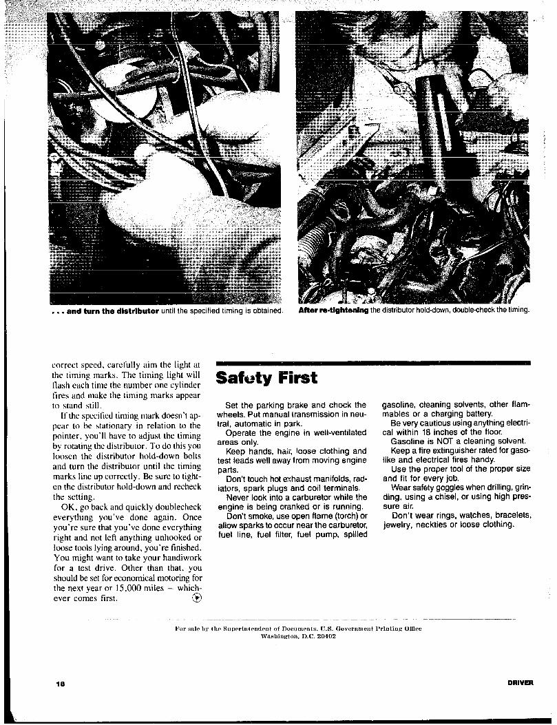
,.. and turn the dlstrlbutor until the specified timing is obtained. After remtlghtenlng the distributor hold-down, double-check the timing.
correct speed, carefully aim the light at the timing marks. The timing light will flash each time the number one cylinder tires and make the timing marks appear to stand still.
If the specified timing mark doesn’t ap- pear to be stationary in relation to the pointer. you’ll have to adjust the timing by rotating the distributor. To do this you loosen the distribumr hold-down bolts and turn the distributor until the timing marks lint up correctly. Be sure to tight- en the distributor hold-down and recheck the setting.
OK. go back and quickly doublecheck everythmg you’ve done again. Once you’re sure that you’ve done everything right and not left anything unhooked or loose tools lying around, you’re finished. You might want to take your handiwork for a test drive. Other than that, you should be set for economical motoring for the next year or 15,000 miles - which- ever comes first. @
Safety First Set the parking brake and chock the
wheels. Put manual transmission in neu- tral, automatic in park.
Operate the engine in well-ventilated areas only.
Keep hands, hair, loose clothing and test leads well away from moving engine parts.
Don’t touch hot exhaust manifolds, rad- iators, spark plugs and coil terminals.
Never look into a carburetor while the engine is being cranked or is running.
Don’t smoke, use open flame (torch) or allow sparks to occur near the carburetor, fuel line, fuel filter, fuel pump, spilled
gasoline, cleaning solvents, other flam- mables or a charging battery.
Be very cautious using anything electri- cal within 18 inches of the floor.
Gasoline is NOT a cleaning solvent. Keep a fire extinguisher rated for gaso-
like and electrical fires handy. Use the proper tool of the proper size
and fit for every job. Wear safety goggles when drilling, grin-
ding. using a chisel, or using high pres- sure air.
Don’t wear rings, watches, bracelets, jewelry, neckties or loose clothing.
1% de IIS the Superintendent of Documents. U.S. Government I’rintiug Ofnce Washington. D.C. 20402
18 DRIVER