Gasoline and Diesel Fuel Injection:Operation, Diagnosis,and Service
37
669 FUEL INJECTION Electronic gasoline fuel-injection systems from the mid 1970s to the mid 1990s and later are all very sim- ilar in design and operation because they share a com- mon beginning with Robert Bosch GmbH, a German company. Bosch is the largest supplier of fuel-injection systems in the world. It doesn’t matter if it’s a Fiat, Ferrari or a Ford, a Nissan, Toyota, Chevrolet, or a Chrysler, Bosch either designed or supplied the com- plete system or some components in the system. In the mid-1990s, automobile manufacturers began moving away from the original Bosch design and we now see many variations. However, Bosch is still a major com- ponent supplier for many of these late systems. BASIC GASOLINE FUEL- INJECTION OPERATION Most fuel-injection systems are closed loop, which means that any fuel sent to the injectors and not used in the engine will be returned to the fuel tank. See Figure 29–1. Fuel Pump The electric fuel pump delivers fuel from the tank to the system and develops fuel pressure. See Fig- ure 29–2. The pump is usually located inside the fuel tank, where it is cooled by the surrounding fuel. Many pumps are incorporated with the fuel gauge sender unit. Some earlier vehicles, usually imports, mounted the pump outside the tank on the frame of the underbody. In-tank pumps are replaced by re- moving the fuel tank or, in some cases, through an access opening in the trunk floor. The roller-cell pump, similar to power steering, is driven by a permanent-magnet electric motor. It pro- vides high-pressure fuel, at about 200 to 350 kPa (30 to 50 psi) for port injection and low-pressure fuel, at about 70 kPa (10 psi) for throttle-body injection. Some Fords use port style injectors in their central fuel-injection (TBI type); system pressures are about 200 kPa (30 psi) for these units. In the event of a restricted fuel filter or line blockage, the pump is capable of producing pres- sures of 700 kPa (100 psi) or higher. An excess pressure valve (relief valve) is built into the pump Gasoline and Diesel Fuel Injection: Operation, Diagnosis, and Service OBJECTIVES: After studying Chapter 29, you should be able to: 1. Prepare for the interprovincial Red Seal certification examination in Appendix VIII (Engine Performance) on the topics covered in this chapter. 2. Describe how to check an electric fuel pump for proper pressure and delivery volume. 3. Explain how to check a fuel-pressure regulator. 4. Describe how to test fuel injectors. 5. Explain how to diagnose gasoline fuel-injection problems. 6. Explain the differences between throttle-body, port and direct fuel-injection. 7. Describe the operation of a diesel mechanical fuel- injection system. 8. Describe the operation of an electronic diesel fuel- injection system. 29
Transcript of Gasoline and Diesel Fuel Injection:Operation, Diagnosis,and Service
669
FUEL INJECTION
Electronic gasoline fuel-injection systems from themid 1970s to the mid 1990s and later are all very sim-ilar in design and operation because they share a com-mon beginning with Robert Bosch GmbH, a Germancompany. Bosch is the largest supplier of fuel-injectionsystems in the world. It doesn’t matter if it’s a Fiat,Ferrari or a Ford, a Nissan, Toyota, Chevrolet, or aChrysler, Bosch either designed or supplied the com-plete system or some components in the system. In themid-1990s, automobile manufacturers began movingaway from the original Bosch design and we now see
many variations. However, Bosch is still a major com-ponent supplier for many of these late systems.
BASIC GASOLINE FUEL-INJECTION OPERATION
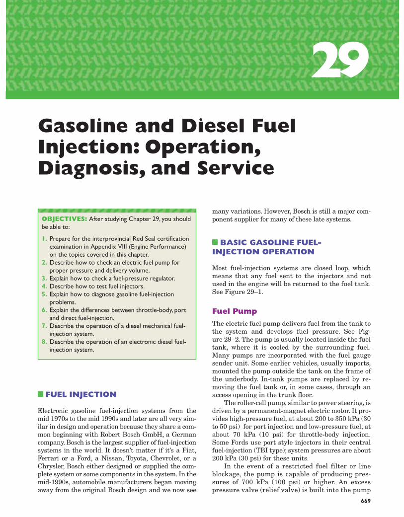
Most fuel-injection systems are closed loop, whichmeans that any fuel sent to the injectors and notused in the engine will be returned to the fuel tank.See Figure 29–1.
Fuel Pump
The electric fuel pump delivers fuel from the tank tothe system and develops fuel pressure. See Fig-ure 29–2. The pump is usually located inside the fueltank, where it is cooled by the surrounding fuel.Many pumps are incorporated with the fuel gaugesender unit. Some earlier vehicles, usually imports,mounted the pump outside the tank on the frame ofthe underbody. In-tank pumps are replaced by re-moving the fuel tank or, in some cases, through anaccess opening in the trunk floor.
The roller-cell pump, similar to power steering, isdriven by a permanent-magnet electric motor. It pro-vides high-pressure fuel, at about 200 to 350 kPa (30to 50 psi) for port injection and low-pressure fuel, atabout 70 kPa (10 psi) for throttle-body injection.Some Fords use port style injectors in their centralfuel-injection (TBI type); system pressures are about200 kPa (30 psi) for these units.
In the event of a restricted fuel filter or lineblockage, the pump is capable of producing pres-sures of 700 kPa (100 psi) or higher. An excesspressure valve (relief valve) is built into the pump
Gasoline and Diesel FuelInjection: Operation,Diagnosis, and Service
OBJECTIVES: After studying Chapter 29, you shouldbe able to:
1. Prepare for the interprovincial Red Seal certificationexamination in Appendix VIII (Engine Performance)on the topics covered in this chapter.
2. Describe how to check an electric fuel pump forproper pressure and delivery volume.
3. Explain how to check a fuel-pressure regulator.4. Describe how to test fuel injectors.5. Explain how to diagnose gasoline fuel-injection
problems.6. Explain the differences between throttle-body, port
and direct fuel-injection.7. Describe the operation of a diesel mechanical fuel-
injection system.8. Describe the operation of an electronic diesel fuel-
injection system.
29
670 CHAPTER 29
Figure 29–1 Typical port fuel-injection system, indicating the location of various components. Notice that the fuel pressure regulator is located on the fuel return side of the system. The computer does not control fuel pressure, but does control the operation of the electric fuel pump (on most systems) and the pulsing on and off of the injectors.
Figure 29–2 Schematic of a roller-cell fuel pump. Note #5 non-return valve, which prevents fuel pressure from bleedingback through the pump, and #2 pressure limiter (relief) valve, which acts as a safety valve if the fuel filter or line is restricted.(Courtesy Robert Bosch)

Fuel Injectors
Electronic fuel injectors are liquid-control solenoidsthat open when electrically activated. See Figure29–5. The injectors are pulsed on and off to controlfuel volume. The longer the injectors are held open,the greater the amount of fuel injected into the man-ifold or intake port. Injectors are never operated at a100% duty cycle. “On” time is called “pulse width”;the longer the pulse width, the greater the fuel flow;“on” time is usually in the 5 to 15 millisecond range.
Port Injection
Port injection systems used on gasoline-powered en-gines inject a fine mist of fuel into the intake mani-fold just above the intake valve. The pressure in theintake manifold is below atmospheric pressure on arunning engine, and the manifold is therefore a vac-uum. See Figure 29–6.
One major advantage of using port injection in-stead of the simpler throttle-body injection is that in-take manifolds on port-injected engines only containair, not a mixture of air and fuel. No pre-heating ofthe manifold is required to vaporize the fuel. This al-lows a cooler charge of intake air, which increasespower. Another advantage is the equal volume offuel provided to each cylinder. These “dry” manifoldsalso allow the engine design engineer the opportu-nity to design long, tuned intake-manifold runnersthat help the engine produce increased torque atlower engine speeds.
Gasoline and Diesel Fuel Injection: Operation, Diagnosis, and Service 671
as a safety feature. A one-way check valve is alsobuilt into the pump outlet to prevent any fuel pres-sure in the lines or rail from bleeding back throughthe pump.
Fuel Filter
The fuel filter is a very important service item. SeeFigure 29–3. It prevents any rust or dirt in the fuelfrom reaching the fuel injectors where damagewould occur; injector blockage, sticking or leakageare the usual result.
The filter is directional and may have an arrowor different sized fittings to prevent mounting back-wards. Filters are normally replaced after a givennumber of kilometres or whenever major service isperformed, e.g., fuel pump replacement or injectorcleaning. Fuel system pressures must be releasedand the fuel tank cap removed before loosening filterlines. Pressurized fuel can spray for a long distance,causing personal injury or a fire.
Fuel Rail (Port Injection)
The fuel rail (or ring) acts as a manifold supplyingfuel to each injector. See Figure 29–4. It also actsas a mounting point for the fuel-pressure regula-tor. Some domestic vehicles have the regulator riv-eted to the fuel rail; both are supplied if eitherneeds replacing. The fuel injectors are sealed withO rings where they mount to the rail; the O ringsshould be replaced whenever the rail is removedfrom the injectors.
Domestic fuel rails usually have a fuel-pressuretest fitting (Schrader valve) mounted on the rail,which makes servicing much easier. Many importedvehicles do not use Schrader valves and require spe-cial adaptors to test system pressures and fuel volume.
Figure 29–3 The fuel filter is located between the fuelpump and the fuel rail. Many filters are directional and havean arrow (or different sized fittings) to prevent incorrectinstallation. Most systems also have a filter “sock” at thefuel tank pick-up. (Courtesy Robert Bosch)
Figure 29–4 The fuel rail is a hollow manifold thatsupplies fuel to the injectors. Excess fuel not used in theengine flows through a pressure regulator (usuallymounted on the rail) and returns to the tank. (CourtesyDaimlerChrysler Corporation)

manifold vacuum is very strong and a givenamount of fuel flows. As the throttle opens, mani-fold vacuum diminishes (pressure in the manifoldrises) and less fuel will flow because of the higherpressure at the injector tip. Vacuum-modulatedpressure regulators increase fuel pressure about35 kPa (5 psi) as the throttle is opened. See Figure29–7. This compensates for the increase in mani-fold pressure.
Any excess fuel not injected into the engine re-turns to the tank via a return line.
The pressure regulator also prevents fuel pres-sure from bleeding into the return line when the en-gine is shut off; this maintains pressurized fuel atthe rail and injectors for faster starting.
672 CHAPTER 29
Figure 29–6 A typical port-injection system squirts fuelinto the low pressure (vacuum) of the intake manifold,about 75 mm (3 in.) from the intake valve. A buildup ofsoft carbon on the intake valve often resulted from thisdesign. The petroleum industry responded in the mid-1990s by increasing the percentage of detergent ingasoline. The detergent also reduced injectorcontamination.
Figure 29–5 Cross-section of a typical port fuel-injection nozzle assembly. These injectors are serviced as an assemblyonly; no part replacement or service is possible other than cleaning or external O-ring replacement. Contamination at theneedle valve area is a common problem, especially with older type injectors. Later injectors, called deposit-resistant, changedthe tip design to reduce the formation of injector deposits.
Fuel Pressure Regulator:Port Injection
Fuel injectors that inject fuel into the intake portare influenced by intake manifold vacuum. At idle,
NOTE: Some port-injection systems used on engineswith four or more valves per cylinder may use two in-jectors per cylinder. One injector is used all the time,and the second injector is operated by the computerwhen high engine speed and high-load conditions aredetected by the computer. Typically, the second injectorinjects fuel into the high-speed intake ports of the man-ifold. This system permits good low-speed power andthrottle response as well as superior high-speed power.

Injector Firing Strategy
Fuel injectors have a number of operating strate-gies. They can all be fired at the same time (see Fig-ure 29–8) with only one driver transistor. This isknown as simultaneous injection; it is not timed.Some systems operate with two driver transistors;half of the injectors fire on one revolution, the otherhalf fire on the second revolution; they also are nottimed. Sequential injection, which requires a sepa-rate ground wire and transistor for each injector(ground side controlled), is timed. Injection usuallyoccurs at the end of the exhaust stroke as the in-take valve is opening.
Sequential injection has a number of advan-tages over simultaneous injection: 1) Emissionsare reduced during low RPM and idle conditions.2) It works with waste spark ignitions that fire thespark plug every revolution. 3) OBD II systemshave the ability to cancel fuel delivery to any cylin-der that is misfiring. This protects the catalyticconverter.
Many imported vehicles use a resistor, which re-duces the voltage at the injectors to approximatelyone-quarter of source voltage. This allows the use oflow resistance injectors, which improves injector re-sponse. Domestic vehicles operate the injectors atsource voltage and regulate injector response withthe PCM.
Overspeed protection is also built into most com-puter programs. If the engine is operated above redline or is over-revved in neutral, the computer cutsoff every second injector (or similar strategy) to bringthe RPM down to a safe level.
Fuel Pump Electrical Circuits
The computer usually controls the operation of theelectric fuel pump, located in (or near) the fuel tank.When the ignition switch is first turned on, the com-puter energizes the fuel pump relay and the pumpoperates. See Figure 29–9. If the computer does notreceive a signal that the engine is rotating, the pumpwill be shut off after 2 to 3 seconds. When the com-puter receives information that the engine is beingcranked, or has started, it continues to energize thefuel pump. The signal may come from one or more ofthe following:
■ Movement inside the vane airflow sensor fromair entering the engine.
■ Oil pressure is noted at the oil pressure sender.■ An ignition tach signal (RPM) is present; this is
the most common.
Gasoline and Diesel Fuel Injection: Operation, Diagnosis, and Service 673
Figure 29–7 The vacuum-modulated pressure regulatorcontrols system fuel pressure with a spring-loadeddiaphragm. (a) Strong manifold vacuum (closed throttle)works against the spring and fuel pressure decreases. (b) Asmanifold vacuum drops (throttle opens), full spring pressureis now exerted on the diaphragm and fuel pressure rises.(Courtesy DaimlerChrysler Corporation)
Figure 29–8 Wiring schematicfor a simultaneous injectionsystem. (Courtesy ToyotaCanada Inc.)

Inertia Safety Switch
Ford, Jaguar and Fiat use an inertia switch in thefuel pump circuit to shut off the fuel pump in case ofan accident. See Figure 29–10. A permanent magnetholds a steel ball in place; if an accident, or sharp im-pact, occurs, the steel ball breaks free and strikes atarget plate, which opens the switch contacts, shut-
NOTE: This is a safety feature: if the engine stalls andthe tachometer (engine speed) signal is lost, the com-puter will shut off (de-energize) the fuel pump relayand stop the fuel pump.
674 CHAPTER 29
Figure 29–9 Schematic of a Fordfuel pump electrical circuit. After2 to 3 seconds of pump operation,the computer (ECA) must receivean ignition signal (indicating theengine is rotating) or it will shutdown the fuel pump relay. Notethe inertia safety switch in thepump circuit. (Courtesy FordMotor Co.)
Figure 29–10 The inertia switch is used to shut off the electric fuel pump in case of an accident. Do not reset the switchbefore checking for fuel leaks at the tank, lines, or engine compartment. (Courtesy Ford Motor Co.)
ting off power to the pump. The switch is reset man-ually by depressing the reset button. Switch loca-tions vary between vehicles; the switch may be in thetrunk, on the firewall or behind a kick panel. Checkthe manual for location.
THROTTLE BODY INJECTION
Throttle-body injection (TBI) is also known as Cen-tral Fuel Injection (CFI) or Single-Point Injection.Throttle-body type of fuel injection uses one or two in-jectors (nozzles) to spray atomized fuel into the throt-tle body, which is similar to the base of a carburetor.

Air and fuel mix in the throttle-body unit and flow asa mixture down the intake manifold to the intakevalves. See Figure 29–11. The fuel pump, filter, andlines are essentially the same as port injection. SeeFigure 29–12. Because fuel is injected above thethrottle plate, intake manifold vacuum has no majorinfluence on the injector. Fuel pressure regulators arenot vacuum-modulated; fuel pressure is constant at70 to 105 kPa (10 to 15 psi) depending on the model.
The ball-type tip of the TBI/CFI fuel injector ismuch larger than the needle tips of port injectorsand it is prone to drip after the engine is shut off. SeeFigure 29–13. Some TBI pressure regulators (GM,Renault) have a bleed groove built into the pressure-regulator valve seat to relieve fuel pressure after theengine is turned off. Be aware of this condition whentesting residual fuel pressure; there will be no pres-sure remaining after a few seconds.
Gasoline and Diesel Fuel Injection: Operation, Diagnosis, and Service 675
A typical TBI system uses a throttle-position (TP)sensor and an idle air-control (IAC) valve.The TP isan input to the computer and the IAC is an outputfrom the computer. The throttle-body injection unitcosts less to manufacture, because it only uses one ortwo injectors (nozzles), whereas port-injection systemsrequire an injector for every cylinder plus the addi-tional computer capabilities to control all the injectors.
Throttle body injection provides better driveabil-ity and fuel economy than a mechanical (or electron-ically controlled) carburetor, however all of the dis-tribution and vaporization problems associated withcarburetted systems apply, as both air and fuel flowthrough the manifold. Unlike a port-injection sys-tem, many TBI units require that heated air be usedwith a heated intake manifold system to help vapor-ize the fuel that is injected into the incoming air in-side the throttle-body unit.
Figure 29–11 Fuel is injectedabove the throttle plate in thisCFI system. The pressureregulator is not vacuum-modulated, as intake manifoldvacuum does not have a majorinfluence on injection rates.(Courtesy Ford Motor Co.)
Figure 29–12 Fuel delivery and return lines on this TBI system are similar to port fuel injection. (Courtesy GeneralMotors)

676 CHAPTER 29
Figure 29–13 A low-pressure TBI/CFI fuel injector feeds all cylinderscompared to a port fuel injector, which feeds only one cylinder. Thelarger ball-type injector tip is prone to leak or drip when the engine hasbeen shut off. (Courtesy Ford Motor Co.)
Figure 29–14 Schematic of a Bosch CIS mechanical injection system. These units are found only on European vehicles.(Courtesy Robert Bosch)
BOSCH CONTINUOUSINJECTION (CIS)
Bosch continuous injection systems are also known asK-Jetronic injection: K stands for konstant in Ger-man. They are found on many 1970s to 1990s Euro-pean vehicles (i.e., Audi, BMW, Mercedes, Volkswagenand Volvo, never on Asian or domestic automobiles).
Early CIS systems were mechanically operated;there is no computer. See Figure 29–14. Later systems,known as CIS-E, used a computer, a lambda (oxygen)sensor and a frequency valve to trim fuel mixtures.The frequency valve changes internal fuel pressuresinside the fuel distributor to vary the mixture.

System Operation
Filtered fuel is pumped to the lower chamber of themixture control unit where it is regulated to about500 kPa (75 psi) by the pressure regulator. Excessfuel is returned to the tank.
Basic fuel control begins with an airflow sensorplate mounted next to the mixture control unit. Airentering the engine lifts the sensor plate; thegreater the flow of air, the higher the plate is lifted.The arm on the airflow sensor plate contacts a fuelcontrol valve called a control plunger. As the sensorplate lifts, it pushes on the control plunger, whichalso lifts, increasing fuel delivery. See Figure 29–15.Fuel flows from the mixture control unit to spring-loaded mechanical fuel injectors that open automat-ically when fuel pressure reaches 330 kPa (50 psi).
Gasoline and Diesel Fuel Injection: Operation, Diagnosis, and Service 677
Figure 29–15 Fuel delivery in aBosch CIS fuel distributor is meteredby a control plunger, which is liftedby airflow at the sensor plate.(Courtesy Robert Bosch)
CENTRAL PORT INJECTION
The General Motors CPI system is a combination ofa single electronic TBI-type injector and mechanicalspring-loaded fuel injectors. See the manifold designin Chapter 9, Figure 9–42A.
The CPI fuel system is located inside a two-piecesplit intake manifold. Fuel arriving at the CPI unitis regulated by a built-in pressure regulator thatreturns unused fuel to the tank. The single maxi-injector (computer activated) injects fuel into a base,which contains six nylon tubes connected to six ny-lon fuel injectors (poppet nozzles). Fuel pressure atthe injectors overcomes spring tension and fuel is in-jected into the ports. See Figure 29–16.
Figure 29–16 Central port injection (CPI) operation. (Courtesy General Motors)

Later designs use separate injector solenoidsfor each poppet valve, rather than a single maxi-injector. These systems are used primarily with V-6 and V-8 light truck engines.
RETURNLESS FUEL INJECTION
The most common injection system found from themid 1990s to date is returnless fuel injection. Anin-tank fuel pump module contains the pump, fil-ter, pressure regulator, and fuel gauge, all in oneunit. See Figure 29–17. There is nothing outside
678 CHAPTER 29
Figure 29–17 The fuel pump, gauge, and pressure regulator are all mountedinside the tank with returnless fuel injection. (Courtesy Toyota Canada Inc.)
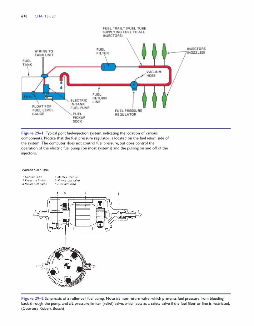
the tank, other than a single fuel line, rail, and in-jectors. See Figure 29–18. The extra computingmemory of the OBD II processor allows fuel volumeto be tailored to demand, regardless of changes inmanifold vacuum.
Removing the rear seat (or trunk mat) and service-hole cover allows access to the unit without remov-ing the tank in most instances.
DaimlerChrysler was one of the first (mid-1990s)to use returnless injection with their V-8 and V-10engines. Since then it has been adopted by many do-mestic and import manufacturers and has becomethe standard around the world.
DIRECT FUEL INJECTION
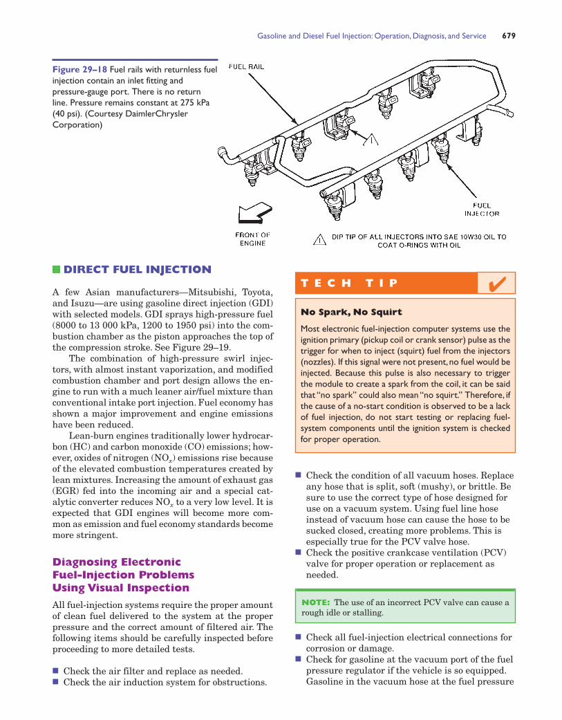
A few Asian manufacturers—Mitsubishi, Toyota,and Isuzu—are using gasoline direct injection (GDI)with selected models. GDI sprays high-pressure fuel(8000 to 13 000 kPa, 1200 to 1950 psi) into the com-bustion chamber as the piston approaches the top ofthe compression stroke. See Figure 29–19.
The combination of high-pressure swirl injec-tors, with almost instant vaporization, and modifiedcombustion chamber and port design allows the en-gine to run with a much leaner air/fuel mixture thanconventional intake port injection. Fuel economy hasshown a major improvement and engine emissionshave been reduced.
Lean-burn engines traditionally lower hydrocar-bon (HC) and carbon monoxide (CO) emissions; how-ever, oxides of nitrogen (NOx) emissions rise becauseof the elevated combustion temperatures created bylean mixtures. Increasing the amount of exhaust gas(EGR) fed into the incoming air and a special cat-alytic converter reduces NOx to a very low level. It isexpected that GDI engines will become more com-mon as emission and fuel economy standards becomemore stringent.
Diagnosing Electronic Fuel-Injection Problems Using Visual Inspection
All fuel-injection systems require the proper amountof clean fuel delivered to the system at the properpressure and the correct amount of filtered air. Thefollowing items should be carefully inspected beforeproceeding to more detailed tests.
■ Check the air filter and replace as needed.■ Check the air induction system for obstructions.
■ Check the condition of all vacuum hoses. Replaceany hose that is split, soft (mushy), or brittle. Besure to use the correct type of hose designed foruse on a vacuum system. Using fuel line hoseinstead of vacuum hose can cause the hose to besucked closed, creating more problems. This isespecially true for the PCV valve hose.
■ Check the positive crankcase ventilation (PCV)valve for proper operation or replacement asneeded.
■ Check all fuel-injection electrical connections forcorrosion or damage.
■ Check for gasoline at the vacuum port of the fuelpressure regulator if the vehicle is so equipped.Gasoline in the vacuum hose at the fuel pressure
NOTE: The use of an incorrect PCV valve can cause arough idle or stalling.
Gasoline and Diesel Fuel Injection: Operation, Diagnosis, and Service 679
T E C H T I P
No Spark, No Squirt
Most electronic fuel-injection computer systems use theignition primary (pickup coil or crank sensor) pulse as thetrigger for when to inject (squirt) fuel from the injectors(nozzles). If this signal were not present, no fuel would beinjected. Because this pulse is also necessary to triggerthe module to create a spark from the coil, it can be saidthat “no spark” could also mean “no squirt.” Therefore, ifthe cause of a no-start condition is observed to be a lackof fuel injection, do not start testing or replacing fuel-system components until the ignition system is checkedfor proper operation.
✔
Figure 29–18 Fuel rails with returnless fuelinjection contain an inlet fitting andpressure-gauge port. There is no returnline. Pressure remains constant at 275 kPa(40 psi). (Courtesy DaimlerChryslerCorporation)

regulator indicates that the regulator is defectiveand requires replacement.
Test Connectors
Many vehicles have test procedures that allow thetechnician to operate the electric fuel pump withoutstarting the engine; these vary between makes, butthe following is typical:
■ Open the meter plate at the vane airflow sensor.See Figure 29–20.
■ Jumper two test terminals at the airflow sensor.■ Jumper specified terminals at the fuel pump relay.■ Ground the fuel-pump test connector (activates
the relay).
■ Power the test connector (powers the fuel pump).■ Activate the fuel pump relay with a scan tool.
Follow the manufacturer’s instructions exactly; awrong connection could ruin the computer, wiring orrelay. See Figure 29–21.
680 CHAPTER 29
Figure 29–19 Gasoline direct injection (GDI). Note the high-pressure swirl fuel injector at the combustion chamber.(Courtesy Toyota Canada Inc.)
Figure 29–20 The vane airflow meter plate should openwith light pressure to the fully open position and return torest without dragging or binding. Many European and Asianvehicles (to mid-1990s) also incorporate fuel-pump safetycontacts; opening the plate with a finger (engine key “on”) willactivate the fuel pump. Domestic vehicles with this type ofmeter use a tach signal, instead of contacts, for pump control.(Courtesy Robert Bosch)
T E C H T I P
The Ear Test
No,this is not a test of your hearing,but rather using yourear to check that the electric fuel pump is operating. Theelectric fuel pump inside the fuel tank is often difficult tohear running, especially in a noisy shop environment. Acommonly used trick to better hear the pump is to use afunnel in the fuel filter neck.
✔
Port Fuel-Injection System Diagnosis
To determine if a port fuel-injection system, includ-ing the fuel pump, injectors, and fuel pressure regu-lator, are operating okay, follow these steps:
1. Attach a fuel pressure gauge to the Schradervalve on the fuel rail.
2. Turn the ignition key on or start the engine tobuild up the fuel pump pressure (it should beabout 210 to 350 kPa [30 to 50 psi]).
3. Wait 20 minutes and observe the fuel pressureretained in the fuel rail and note the value.(The fuel pressure should not drop more than140 kPa [20 psi] in 20 minutes.) If the drop isless than 140 kPa (20 psi) in 20 minutes,everything is okay. If the drop is greater than140 kPa (20 psi) in 20 minutes, there is apossible problem with:• The check valve in the fuel pump• Leaking injectors• A defective (leaking) fuel pressure
regulator
To determine which unit is defective, performthe following with the gauges still connected:
NOTE: Some fuel rails may not have a Schradervalve on the rail and therefore, special adapters maybe required.
Gasoline and Diesel Fuel Injection: Operation, Diagnosis, and Service 681
DIAGNOSTIC STORY
The Quad Four Story
A service technician was diagnosing a rough-running con-dition on a General Motors Quad Four engine. The pa-per test indicated a cylinder miss. To help determinewhich cylinder was possibly causing the problem, thetechnician disconnected the fuel-injector connectors oneat a time. When the injector was disconnected fromcylinder #2, the engine did not change in the way it wasrunning. A compression test indicated that the cylinderhad good compression. The technician removed the igni-tion cover and used conventional spark plug wires toconnect the coils to the spark plugs. The technician thenconnected short lengths of rubber vacuum hose to eachof the plugs. The technician then touched each rubberhose with a grounded test light to ground out each cylin-der. Again, cylinder #2 was found to be completely dead.
Then the technician made a mistake by assumingthat the fault had to be a defective fuel injector. A re-placement fuel injector did not solve the problem. Fur-ther testing of the injectors revealed that injector #3was shorted. Because both injectors #2 and #3 sharethe same driver inside the computer, the injector thatwas shorted electrically required more current than thenormal good injector. Because the computer driver cir-cuit controls and limits current flow, the defective(shorted) injector would fire (squirt), whereas the goodinjector did not have enough current to work.
CAUTION: The use of fuel-injector cleaner may damagethe electrical windings of the fuel injector. Gasoline flows overthe copper coil windings of an injector to help keep it cool. Ifa strong solvent is used in the fuel-injection cleaner,the varnishinsulation on the coil may be damaged. As a result, the coilwindings may short against each other, lowering the resistanceof the injector.
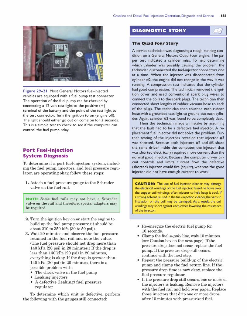
Figure 29–21 Most General Motors fuel-injectedvehicles are equipped with a fuel pump test connector.The operation of the fuel pump can be checked byconnecting a 12 volt test light to the positive (�)terminal of the battery and the point of the test light tothe test connector. Turn the ignition to on (engine off).The light should either go out or come on for 2 seconds.This is a simple test to check to see if the computer cancontrol the fuel pump relay.
• Re-energize the electric fuel pump for10 seconds.
• Clamp the fuel supply line, wait 10 minutes(see Caution box on the next page). If thepressure drop does not occur, replace the fuelpump. If the pressure drop still occurs,continue with the next step.
• Repeat the pressure build-up of the electricpump and clamp the fuel return line. If thepressure drop time is now okay, replace thefuel pressure regulator.
• If the pressure drop still occurs, one or more ofthe injectors is leaking. Remove the injectorswith the fuel rail and hold over paper. Replacethose injectors that drip one or more dropsafter 10 minutes with pressurized fuel.

TESTING FUEL PUMPPRESSURE
The most common gasoline fuel injection systems op-erate with system pressures ranging from 70 kPa (10psi) on low pressure TBI/CFI to 350 kPa (50 psi) onport injection. There are exceptions, so service speci-fications should always be checked before starting.
Typical System Pressures
Normal MaximumOperating Pump PressurePressure kPa (psi) kPa (psi)
Low-pressure TBI units 70 kPa (10 psi) 140 kPa (20 psi)
High- pressure TBI units 210 kPa (30 psi) 450 kPa (65 psi)
Port fuel-injection systems 350 kPa (50 psi) 700 kPa (100 psi)
Central port fuel injection 420 kPa (60 psi) 700 kPa (100 psi)
Bosch K-Jetronic (mechanical) 525 kPa (75 psi) 700 kPa (100 psi)
Returnless injection 280 kPa (40 psi) 550 kPa (80 psi)
Maximum fuel pressure should never bereached provided the fuel pressure regulator is op-erating and there is no blockage in the filter or lines;blockage before the gauge test fitting may not showa pressure rise at the gauge.
Closed loop injection returns excess fuel to thetank. The continuous flow of fuel cools the injectorand helps prevent vapour from forming in the fuelsystem. Although vapour or foaming in a fuel systemcan affect engine operation, the cooling and lubri-cating flow of the fuel helps to ensure the durabilityof the injector nozzles.
Returnless injection systems cycle any excess fuelat the regulator inside the tank. The fuel is not ex-posed to high underhood temperatures (until it isused at the injectors) or heated by pumping it throughthe rail and back to the tank; the fuel remains cool.
To measure fuel-pump pressure, locate theSchrader valve, if equipped, or install a suitable adap-tor. Attach a fuel pressure gauge as shown in Figure29–22. Check the pressure while the engine idles. Thefuel pressure should remain constant on all systemsother than vacuum modulated port fuel injection wherepressures vary with changes in manifold vacuum.
CAUTION: Do not clamp plastic fuel lines. Connectshut-off valves to the fuel system to shut off supply andreturn lines.
682 CHAPTER 29
T E C H T I P
The Electric Fuel Pump Clue
The on-board computer controls the operation of theelectric fuel pump, fuel-injection pulses, and ignition tim-ing. With a distributorless ignition system, it is difficult attimes to know what part in the system is not operating ifthere is no spark from any of the ignition coils. A fast-and-easy method for determining if the crankshaft sensoris operating is to observe the operation of the electricfuel pump. In most electronic fuel-injection systems, thecomputer will operate the electric fuel pump for only ashort time (usually about 2 seconds) unless a crank pulseis received by the computer.
Most manufacturers provide a fuel pump test leadwith which the technician can monitor the electrical op-eration of the pump. On most vehicles, if voltage is main-tained to the pump during engine cranking for longerthan 2 seconds, then the crankshaft sensor is working. Ifthe pump only runs for 2 seconds then turns off duringcranking of the engine, the crankshaft sensor, wiring, orcomputer may be defective.
NOTE: Another way of testing is to use a scan tool. If anRPM signal is processed and displayed by the computer, thenthe crank sensor is functioning.
✔
DIAGNOSTIC STORY
The Rich-Running Chrysler
A four-cylinder Chrysler was running so rich that blacksmoke poured from the exhaust all the time. It wasequipped with a TBI-type fuel-injector system, and thefuel pressure was fixed at about 260 kPa (38 psi)—thesame as the maximum fuel-pump pressure. A replace-ment fuel-pressure regulator did not correct the higher-than-normal fuel pressure. The fuel return line was alsocarefully inspected for a kink or other obstruction thatmay have caused excessive fuel pressure. The techniciandiscovered the root cause of the problem to be a stuckshuttle valve, a part of many Chrysler TBI systems usedto close off the fuel return to the tank to keep the pres-sure high, permitting faster restarts when the engine ishot. The shuttle valve simply slides downward on an in-cline to close off the fuel regulator return passage. Thetechnician removed the shuttle valve and cleaned it. Ve-hicle operation then returned to normal and both thetechnician and the customer were satisfied that a lowcost and fast solution was found.

Port Fuel-Injection PressureRegulator Diagnosis
Most port fuel-injected engines use a vacuum hoseconnected to the fuel pressure regulator. At idle, thepressure inside the intake manifold is low (high vac-uum). Intake manifold vacuum is applied above thediaphragm inside the fuel pressure regulator. Thisreduces the pressure exerted on the diaphragm andresults in a drop (about 35 kPa or 5 psi) in fuel pres-sure applied to the injectors. To test a vacuum-controlled fuel pressure regulator, follow these steps:
1. Connect a fuel pressure gauge to monitor thefuel pressure.
2. Locate the fuel pressure regulator anddisconnect the vacuum hose from the regulator.
3. Using a hand-operated vacuum pump, applyvacuum, about 500 mm (20 in.) Hg to theregulator. The regulator should hold vacuum. Ifthe vacuum drops, replace the fuel pressureregulator. See Figure 29–23.
4. With the engine running at idle speed, reconnectthe vacuum hose to the fuel pressure regulatorwhile watching the fuel pressure gauge. The fuelpressure should drop (about 35 kPa, 5 psi) whenthe hose is reattached to the regulator.
Testing Fuel-Pump Volume
Fuel pressure alone is not enough for proper engineoperation. Sufficient fuel capacity (flow) must be atleast 1 litre (2 pints) per minute (0.5 litre or 1 pintin 30 seconds).
NOTE: If gasoline drips out of the vacuum hose whenremoved from the fuel pressure regulator, the regulatoris defective and will require replacement. All fuel must be filtered to prevent dirt and im-
purities from damaging the fuel-system componentsand/or engine. The first filter (sock) is inside the gastank and is usually attached to the fuel pump (if thepump is electric) and/or fuel-gauge sending unit. Themain fuel filter is usually located between the fueltank and the fuel rail or inlet to the fuel-injectionsystem. For long engine and fuel-system life and op-timum performance, the main fuel filter should bereplaced every year or every 24 000 km (15 000 mi).Consult vehicle manufacturers’ recommendationsfor exact time and kilometre (mileage) intervals.
If the fuel filter becomes partially clogged, thefollowing are likely to occur:
1. There will be low power at higher enginespeeds. The vehicle usually will not go fasterthan a certain speed (engine acts as if it has abuilt-in speed governor).
Gasoline and Diesel Fuel Injection: Operation, Diagnosis, and Service 683
FUELPRESSUREREGULATOR
Figure 29–23 If the vacuum hose is removed from the fuelpressure regulator when the engine is running, the fuelpressure should increase. If it does not increase, then the fuelpump is not capable of supplying adequate pressure or thefuel pressure regulator is defective. If gasoline is visible in thevacuum hose, the regulator is leaking and should be replaced.
Figure 29–22 A fuel pressure gauge connected to the fuelpressure tap (Schrader valve) on a port-injected V-6 engine.

2. The engine will cut out or miss on acceleration,especially when climbing hills or during heavy-load acceleration.
A weak or defective fuel pump can also be the causeof the symptoms just listed. If an electric fuel pump fora fuel-injected engine becomes weak, the engine mayalso be hard to start, or it will idle rough or stall.
NOTE: Most electric fuel pumps have a life ex-pectancy of about 160 000 km (100 000 mi) before re-placement. The usual cause of failure is brush wear atthe commutator. Some manufacturers are now usingbrushless, permanent magnet fuel pumps, which pro-vide a major improvement in service life.
CAUTION: Be certain to consult the vehicle manu-facturer’s recommended service and testing proceduresbefore attempting to test or replace any component of ahigh-pressure electronic fuel-injection system.
684 CHAPTER 29
T E C H T I P
Stethoscope Fuel Injection Test
A commonly used test for injector operation is to listento the injector with a stethoscope while the engine is op-erating at idle speed. See Figure 29–24. All injectorsshould produce the same clicking sound. If any injectorsounds different from the others, further testing or re-placement may be necessary. All injectors should make a“clicking” sound. If any injector makes a “clunking” or“rattling” sound, it should be tested further or replaced.With the engine still running, place the end of the stetho-scope probe to the return line from the fuel pressure reg-ulator. See Figure 29–25. The sound of fuel should beheard flowing back to the fuel tank. If no sound of fuel isheard, then the fuel pump, fuel filter, or the fuel pressureregulator is at fault.
✔
FUEL PRESSUREREGULATOR
FUELRETURNLINE TOTANK
Figure 29–25 Fuel should be heard returning to the fueltank at the fuel return line if the fuel pump and fuelpressure regulator are functioning correctly.
Figure 29–24 All fuel injectors should make the samesound with the engine running at idle speed. A lack ofsound indicates a possible electrically open injector or abreak in the wiring. A defective computer could also be thecause of a lack of clicking (pulsing) of the injectors.
T E C H T I P
Fuel-system pressure is controlled by a fuel pressure reg-ulator at the fuel rail or throttle body. A restricted fuelfilter or line will cause fuel pressure to increase,up to 700kPa (100 psi) in some cases. The fuel pump slows downbecause of the added load and usually becomes noisier. Acomplaint of “whining noise in the rear” could be cor-rected by replacing the fuel filter. A fuel volume test (af-ter the filter) will verify the diagnosis.
✔S A F E T Y T I P
The arcing of the electric current from the fuel pumpbrushes to the armature commutator will not cause agasoline fire or explosion, as there is insufficient oxygenin the pump while it is mounted on the vehicle.
This is not true if the pump has been removed fromthe vehicle; any remaining fuel vapours will mix with air ifthe pump is electrically activated (tested) off the vehicle.The pump could explode! Always follow the manufactur-ers’ procedures when testing pumps.
Possible noid light problems and causes includethe following:
1. The light is off and does not flash. Theproblem is an open in either the power side orground side (or both) of the injector circuit.
2. The noid light flashes dimly. A dim noid lightindicates excessive resistance or low voltageavailable to the injector. Both the power andground side must be checked.
3. The noid light is on and does not flash. Ifthe noid light is on, then both a power and aground are present. Because the light does notflash (blink) when the engine is being cranked orstarted, then a short-to-ground fault existseither in the computer itself or in the wiringbetween the injector and the computer.
Checking Fuel-Injector Resistance
Each port fuel injector must deliver an equalamount of fuel or the engine will idle rough or per-form poorly.
The electrical balance test involves measuringthe injector coil-winding resistance. For best engineoperation, all injectors should have the same electri-cal resistance. To measure the resistance, carefullyrelease the locking feature of the connector and re-move the connector from the injector.
Always check the service information for the ex-act specifications for the vehicle being checked.
With an ohmmeter, measure the resistanceacross the injector terminals. Be sure to use the low-ohms feature of the digital ohmmeter to be able toread in tenths (0.1) of an ohm. See Figures 29–27 and29–28. Subtract the lowest reading injector from thehighest. For example,
Highest-resistance injector � 17.4 ohms
� Lowest-resistance injector � 17.2 ohms
Difference � 0.2 ohms
Acceptable maximum differences should belimited to 0.3 to 0.4 ohms. A greater difference inresistance indicates a possible problem. Furthertesting should be performed. The resistance of the
NOTE: Some engines require specific procedures togain access to the injectors. Always follow the manu-facturers’ recommended procedures.
NOTE: The term noid is simply an abbreviation of theword solenoid. Injectors use a movable iron core andare therefore a solenoid. Therefore, a noid light is a re-placement for the solenoid (injector).
Gasoline and Diesel Fuel Injection: Operation, Diagnosis, and Service 685
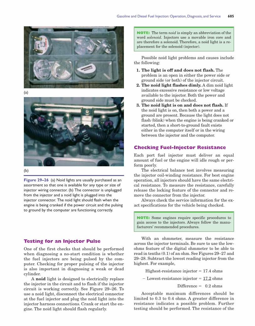
Figure 29–26 (a) Noid lights are usually purchased as anassortment so that one is available for any type or size ofinjector wiring connector. (b) The connector is unpluggedfrom the injector and a noid light is plugged into theinjector connector. The noid light should flash when theengine is being cranked if the power circuit and the pulsingto ground by the computer are functioning correctly.
(a)
(b)
Testing for an Injector Pulse
One of the first checks that should be performedwhen diagnosing a no-start condition is whetherthe fuel injectors are being pulsed by the com-puter. Checking for proper pulsing of the injectoris also important in diagnosing a weak or deadcylinder.
A noid light is designed to electrically replacethe injector in the circuit and to flash if the injectorcircuit is working correctly. See Figure 29–26. Touse a noid light, disconnect the electrical connectorat the fuel injector and plug the noid light into theinjector harness connections. Crank or start the en-gine. The noid light should flash regularly.

686 CHAPTER 29
Figure 29–27 Connections and settings necessary to measure fuel-injector resistance.(Courtesy of Fluke Corporation)
Figure 29–28 To measure fuel-injector resistance, atechnician constructed a short wiring harness with adouble banana plug that fits into the V and COM terminalsof the meter and an injector connector at the other end.This setup makes checking resistance of fuel injectorsquick and easy.
injectors should be measured twice—once whenthe engine (and injectors) are cold and once afterthe engine has reached normal operating temper-ature. If any injector measures close to or over1.0 ohm different from the others, it must be re-placed after making certain that the terminals ofthe injector are electrically sound.
Measuring Resistance of Grouped Injectors
Many vehicles are equipped with a port fuel-injection system that fires two or more injectors ata time. For example, a V-6 may group all three in-jectors on one bank to pulse on at the same time,then the other three injectors will be pulsed on.This sequence alternates. To measure the resis-tance of these injectors, it is often easiest to mea-sure each group of three that is wired in parallel.The resistance of three injectors wired in parallel

Gasoline and Diesel Fuel Injection: Operation, Diagnosis, and Service 687
MAP SENSOR INTAKE MANIFOLD
INJECTORWIRINGCONNECTOR
Figure 29–29 The fuel injector wiring connector on thisGeneral Motors 3.1-litre V-6 is hidden and attached to therear of the intake manifold. Both groups of three injectorscan be easily measured using an ohmmeter. Both groups ofinjectors should measure within 0.5 ohm of each other.
Figure 29–30 The injector on-time is called the pulse width. (Courtesy of Fluke Corporation)
tance. If both groups measure 4 ohms, then it islikely that all six injectors are okay. However, if onegroup measures only 2.9 ohms and the other groupmeasures 4 ohms, then it is likely that one or morefuel injectors are defective (shorted). This meansthat the technician now has reasonable cause to re-move the intake manifold to get access to each injec-tor for further testing. See Figure 29–29.
Pressure-Drop Balance Test
The pressure balance test involves using an electri-cal timing device to pulse the fuel injectors on for agiven amount of time (usually 500 milliseconds)and observing the drop in pressure that accompa-nies the pulse. If the fuel flow through each injectoris equal, the drop in pressure in the system will beequal. Most manufacturers recommend that thepressures be within about 10 kPa (1.5 psi) of eachother for satisfactory engine performance. This testmethod not only tests the electrical functioning ofthe injector (for definite time and current pulse) butalso tests for mechanical defects that could affectfuel flow.
Scope Testing Fuel Injectors
A scope such as a digital storage oscilloscope (DSO)can be attached to the pulse side of the injector andthe waveform checked and compared to a known-good pattern. See Figures 29–30 and 29–31.
is one-third of the resistance of each individual in-jector. For example,
Injector resistance� 12 ohmsThree injectors in parallel� 4 ohms
A V-6 has two groups of three injectors. There-fore, both groups should measure the same resis-

CLEANING FUEL INJECTORS
Most fuel injectors can be cleaned on the vehicle byfeeding injector-cleaning liquid into the fuel rail, orTBI/CFI test port while the engine is running.
One common piece of equipment is shown inFigure 29–32. Liquid cleaner, which may requirediluting with gasoline, is poured into the containerafter the top has been unscrewed. The top, con-taining an adjustable air pressure regulator, is re-installed and a shop air hose is attached to theregulator. Ensure that the shut-off valve is closed
and adjust the container pressure to 35 kPa (5 psi)lower than the fuel-injection-system operatingpressure. TBI/CFI systems operate with low pres-sures; a 15 kPa (2 psi) lower setting is fine withthese units.
Hang the cleaning unit under the hood and at-tach the supply hose to the Schrader valve (or adap-tor) on the fuel rail or as directed in the operating in-structions. Disconnect the wiring to the electric fuelpump on the vehicle. Block the fuel return line byclamping, if rubber, or by installing a shut-off valveif plastic or plastic-lined. See Figure 29–33.
688 CHAPTER 29
Figure 29–31 A typical peak and holdfuel-injector waveform. Most fuelinjectors that measure less than 6 ohmswill display a similar waveform.(Courtesy of Fluke Corporation)
Figure 29–32 Fuel-injector cleaner is fed into the fuel system with thiscleaning unit; shop air is attached to the regulator fitting. Aerosol cans,already pressurized and containing pre-mixed cleaner, are also used; however,they contain less cleaner and are often more expensive. (Courtesy OTCDivision, SPX Corporation)

Open the shut-off valve, start the engine and letit run until the container runs out of fluid. Some man-ufacturers recommend a fast idle only; others run theengine at various speeds. Remove the equipment, re-connect the pump, remove the return line shut-off,restart the engine and check the injector operation.
Cleaning the injectors on the vehicle will usuallycorrect leaking or contamination at the injector tip;if this operation is not successful, the injectors mustbe removed for electronic cleaning (high frequencyvibration) or replacement.
Remember always to keep a fire extinguisher,(suitable for gasoline) on hand whenever workingwith fuel injection.
IDLE AIR SPEED CONTROL
On an engine equipped with fuel injection (TBI orport injection), the idle speed is controlled by in-creasing or decreasing the amount of air bypassingthe throttle plate. Again, an electronic stepper motoris used to maintain the correct idle speed. This con-trol is often called the idle air control (IAC). SeeFigures 29–35 through 29–37.
When the engine stops, most IAC units will ex-tend the conical valve until the valve bottoms inthe air bypass passage. The computer notes thisposition and then moves the valve outward to get
Gasoline and Diesel Fuel Injection: Operation, Diagnosis, and Service 689
Figure 29–33 Typical hookup for on-vehicle injector cleaning. Note the blocked fuel return line and the unplugged wiring to the fuel pump. (Courtesy OTC Division, SPX Corporation)
Frequently Asked Question
If Three Out of Six Injectors Are Defective, Should I Also Replace the Other Three?
This is a good question. Many service technicians recom-mend that the three good injectors also be replacedalong with the other three that tested as being defective.The reasons given by these technicians include:
• All six injectors have been operating under the samefuel, engine, and weather conditions.
• The labour required to replace all six is just about thesame as replacing only the three defective injectors.
• Replacing all six at the same time helps ensure thatall of the injectors are flowing the same amount offuel so that the engine is operating most efficiently.
With these ideas in mind, the customer should be in-formed and offered the choice. Complete sets of injec-tors such as those in Figure 29–34 can be purchased at areasonable cost.
???
Figure 29–34 A set of six new injectors.

ready for the next engine start. When the enginestarts, the engine speed is high to provide forproper operation when the engine is cold. Then, asthe engine gets warmer, the computer reduces en-gine idle speed gradually by reducing the numberof counts or steps commanded by the IAC.
When the engine is warm and restarted, the idlespeed should momentarily increase, then decrease tonormal idle speed.This increase and then decrease inengine speed is often called an engine flare. If the en-gine speed does not flare, then the IAC may not beworking (it may be stuck in one position).
Some air control valves (Ford, Hitachi) can be re-moved and disassembled for cleaning. Never use liq-uid cleaners on electrical components or plastic con-trol valves as damage can occur.
THROTTLE BODIES:PORT FUEL INJECTION
Throttle Body Icing
Port fuel injection manifolds are not heated; air onlypasses through the runners. Under certain low tem-perature, high humidity conditions, moisture in theincoming air will freeze at the throttle plate area ofthe throttle body. Many current throttle bodies in-corporate a pocket, or passage, for engine coolant towarm the body. See Figure 29–38.
Electronic Throttle Control
Most electronic throttle control systems do not use athrottle cable. An electric motor on the side of thethrottle body operates the throttle plate when com-manded by the PCM.An accelerator position sensor at
690 CHAPTER 29
Figure 29–35 An idle air control (IAC) controls idlespeed by controlling the amount of air that passes aroundthe throttle plate. More airflow results in a higher idlespeed. (Courtesy of Fluke Corporation)
Figure 29–36 A typical IAC.
Figure 29–37 Some idle air control units are purchasedwith the housing as shown. Carbon buildup in thesepassages can cause a rough or unstable idling or stalling.

the accelerator pedal sends a signal to the PCM, whichin turn, adjust the throttle motor to match the driver’sinput.The throttle position sensor on the throttle bodysends throttle angle information to the PCM.
Electronic throttles originated with tractioncontrol systems where the computer reduces throt-tle opening when wheel spin is detected. Sincethen, it has become common with or without trac-tion control.
Conditions of excessive RPM or engine overheat-ing may also trigger reduced throttle opening.
Throttle Plate Contamination
The positive crankcase ventilation (PCV) systempicks up ventilating air, usually between the massairflow sensor and the throttle plate. See Figure29–39. Crankcase fumes often backfeed into thethrottle body causing a buildup of deposits at thethrottle plate and bore. These deposits are normallyremoved during regular maintenance service orwhen a driveability concern is noted.
The throttle plates of a port fuel-injected enginemay require cleaning, especially if the following con-ditions exist:
■ Rough idle■ Stalling■ Surging at idle
■ Hesitation during acceleration■ Higher than normal IAC counts as displayed on
a scan tool.
See Figures 29–40 and 29–41.
FALSE AIR
Speed density fuel injection relies on informationtypically from MAP, CTS,ACT, RPM, and TPS for cal-culating fuel delivery. An air leak in the hose be-tween the air cleaner and the throttle body usuallywill not affect driveability.
The opposite is true with mass-air systems; anyair leaks could change the mass airflow sensor read-ing and cause hard starting and rough running. Thisusually occurs during open loop operation when fuelis not being trimmed by the oxygen sensor. See Fig-ures 29–42 and 29–43.
DIESEL FUEL INJECTION
Diesel injection systems have seen many changesover the past few years, driven in part by new, morestringent emissions regulations and a call for in-creased economy. Earlier systems used a mechanicalfuel injection pump to meter fuel delivery; however,
Gasoline and Diesel Fuel Injection: Operation, Diagnosis, and Service 691
Figure 29–38 This electronic throttle body uses engine coolant to prevent throttle plate icing. Note the location of thethrottle control motor and position sensor. (Courtesy Toyota Canada Inc.)

692 CHAPTER 29
Figure 29–41 Some vehicles, such as this Ford, havelabels on the throttle body warning not to clean thethrottle plates. A slippery coating is placed on the throttleplate and throttle bore that prevents deposits fromsticking. Cleaning this type of housing can remove thisprotective coating.
Figure 29–40 (a) Dirty throttle plate. This throttle plate was so dirty that the technician removed the entire throttle bodyto be sure it was thoroughly cleaned. (b) Most throttle plates can be cleaned on the vehicle using a brush and throttle bodycleaner. Be sure the cleaner is safe for oxygen sensors.
(a) (b)
Figure 29–39 Airflow through the positive crankcase ventilation (PCV) system.Note the closure hose at the front cam cover; blow-by gases may back-flow into the air intake under certain driving conditions, i.e., full-throttle, high RPM operation. (Courtesy Toyota Canada Inc.)
this did not allow the precise control required tomeet new standards. Electronic systems were intro-duced in the mid to late 1990s. We will start withconventional fuel injection.
CONVENTIONAL(MECHANICAL) FUEL INJECTION
Conventional fuel injection uses, for the most part, allmechanical components.There is limited electrical use.Other than glow-plug circuits, solenoids, block heaters,and fuel heaters, fuel delivery is governed by a me-chanical injection pump. See Figure 29–44. Althoughhere are variations between makes and engine types,the following is common with most systems.
■ Fuel tanks—Very similar to gasoline vehicles;multiple tanks are often used for long distancevehicles such as vans or pick-up trucks. The fuelsupply line in the tank usually contains a pre-filter to limit large contaminants from enteringthe system.
■ Lift pump—Transfers fuel from the fuel tank,through the fuel filter and on to the deliverysystem. This may be an electric pump or amechanical pump driven by the engine.
■ Fuel filter—Very important with a diesel engineas any small particles or abrasives that get pastthe filter may cause damage to the injectionpump or injectors. See Figure 29–45. Handpriming pumps are often found on the fuel filter;they are used to remove trapped air from the fuelsystem and to force fuel to the injection pump.Many late-model systems remove airautomatically.
■ Water/fuel separators—Water in the fuel createsa number of driveability problems as well assystem damage. Water is heavier than diesel fueland will accumulate at the bottom of theseparator, where it is drained as part of regularmaintenance. Some separators have a sensorthat illuminates a warning light on theinstrument panel when the water reaches agiven level. See Figure 29–46. Many late-modelsystems incorporate the fuel filter, waterseparator, and fuel heater in one unit.
Gasoline and Diesel Fuel Injection: Operation, Diagnosis, and Service 693
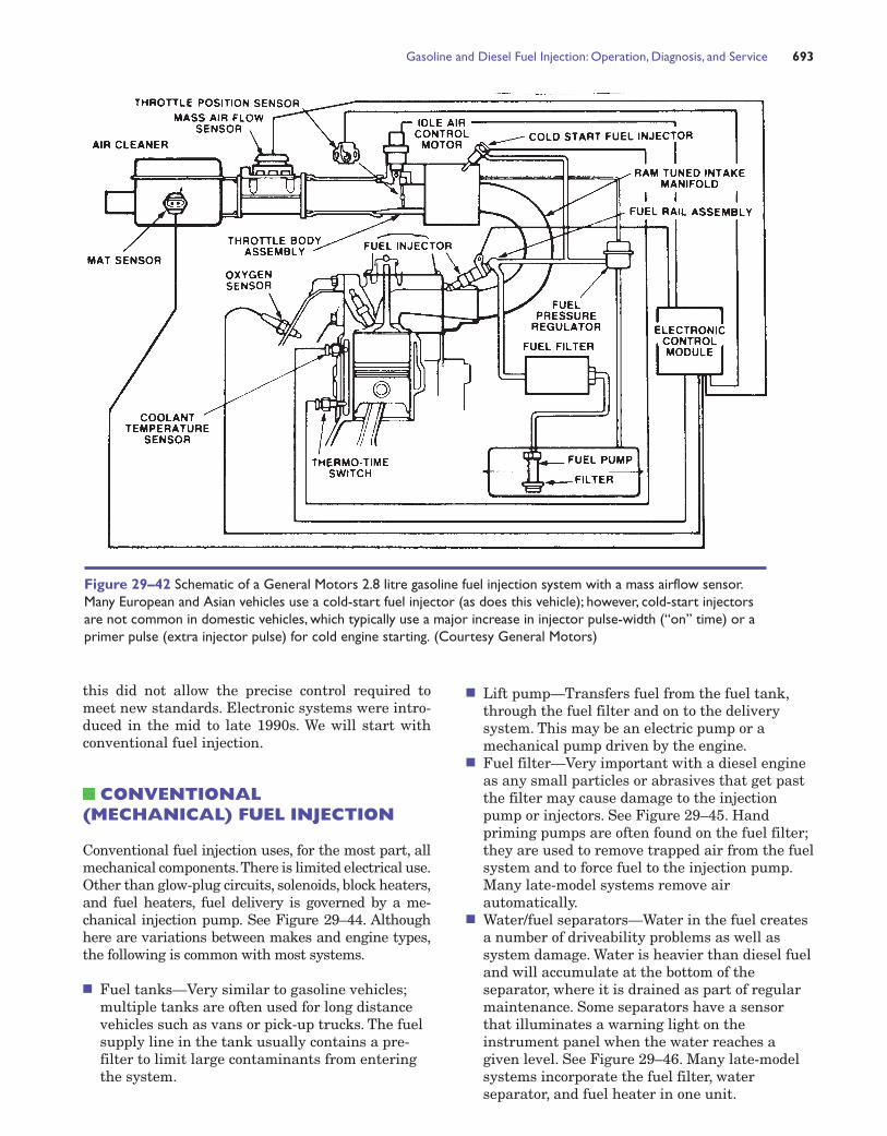
Figure 29–42 Schematic of a General Motors 2.8 litre gasoline fuel injection system with a mass airflow sensor.Many European and Asian vehicles use a cold-start fuel injector (as does this vehicle); however, cold-start injectorsare not common in domestic vehicles, which typically use a major increase in injector pulse-width (“on” time) or aprimer pulse (extra injector pulse) for cold engine starting. (Courtesy General Motors)

■ Fuel heaters—Because diesel fuel has a tendencyto wax and thicken when cold, electric heatersare often used to warm the fuel. Canadian dieselfuels are also blended to match seasonaltemperatures; a very light fuel is supplied forwinter use.
■ Fuel injection pump—Diesel fuel must beinjected into the combustion chamber area at
extremely high pressure, over 17 500 kPa (2500psi), to overcome cylinder pressures.
An injection pump increases fuel pressure, con-trols speed and power by metering the volume of fuelinjected, and directs the fuel to the correct injector. Itmay also contain a governor, which limits the maxi-mum RPM of the engine, and a fuel shut-off.
694 CHAPTER 29
Figure 29–43 The Bosch L-Jetronic (L stands for luft, which is “air” in German) gasoline fuel injection system. Thevane airflow sensor measures airflow, not mass. It is not as accurate as a mass air sensor, but it is a major improvementover speed-density systems. L-Jetronic injections are used on many European, Asian and some domestic vehicles fromthe mid-1970s to the mid-1990s. (Courtesy Robert Bosch)

Gasoline and Diesel Fuel Injection: Operation, Diagnosis, and Service 695
Figure 29–45 A diesel fuel filter with built-in primingpump. (Courtesy Ford Motor Co.)
Figure 29–46 A water/fuel separator with a water levelwarning light. (Courtesy Ford Motor Co.)
Figure 29–44 Schematic of the fuel delivery and return on a conventional (mechanical) diesel fuel injection. (CourtesyFord Motor Co.)

FUEL INJECTION PUMPS
Two types of mechanical injection pumps are commonwith conventional systems: the in-line and the rotary.
In-line Injection Pumps (4-Cycle)
In-line pumps are usually found on large trucks andolder passenger car/light truck applications.See Figure29–47.The pump is driven at one-half the engine speed,which means the injection-pump camshaft makes onecomplete revolution for each two turns of the engine.When the pump cam lobe pushes up on the cam followerand plunger, the fuel above the plunger is put undervery high pressure. See Figure 29–48. This high-
pressure fuel opens the delivery valve spring, which al-lows fuel to move through steel lines to the injectors,where it is supplied to the engine. See Figure 29–49.
696 CHAPTER 29
Figure 29–47 An in-linediesel injection pump.(Courtesy Ford Motor Co.)
Figure 29–48 A diesel fuel injection pump: start of injection. (Courtesy Ford Motor Co.)
S A F E T Y T I P
Never check for fuel leaks by runningyour hand over the lines—a high pressureleak could penetrate your skin, enter theblood stream and cause poisoning.
It is good practice, instead, to move a piece of lightcoloured cardboard along the lines, checking visually forsigns of liquid fuel on the cardboard. See Figure 29–50.

Fuel Control—In-line InjectionPump
Remember that diesels do not use a throttle plate;under most operating conditions the engine takes infar more air than it requires. Power and speed arecontrolled by the amount of fuel injected; more fuelequals higher speed and greater power.
Note the control rack in Figure 29–51, which isconnected to the accelerator pedal. As the rack ismoved in or out, it rotates a gear and control sleeve,which turns the plunger.
A tapered groove, called the helix, is machinedinto the plunger. This increases or decreases theamount of fuel as the plunger is rotated. The helixcontrols fuel volume by opening or restricting a pas-sage to the spill port: a large opening means less fuel
is left in the barrel for injection, a restricted openingleaves more fuel in the barrel and a greater volumeof fuel is injected. See Figure 29–52.
Governors
Governors are usually incorporated into the fuel in-jection pump where engine speed is controlled bylimiting the amount of fuel supplied to the injectors.The most common type of in-line pump governoruses flyweights, which are held in by spring pres-sure. See Figure 29–53. At higher RPM, centrifugalforce causes the flyweights to move outward againstthe spring; this movement limits fuel-rack travel,which in turn restricts fuel delivery and prevents en-gine over-revving.
Gasoline and Diesel Fuel Injection: Operation, Diagnosis, and Service 697
Figure 29–51 Movement of thecontrol rack in an in-line injectionpump changes the fuel deliveryvolume. (Courtesy Robert Bosch)
Figure 29–49 Fuel passing through the delivery valve tothe injector. (Courtesy Ford Motor Co.)
Figure 29–50 Diesel fuel leak testing. Use cardboard to testfor leaks, NEVER your hand! (Courtesy Ford Motor Co.)

ROTARY DIESEL FUELINJECTION PUMPS
The common rotary pump, often called a distributorpump, uses a rotating motion rather than the recip-rocating action of the in-line pump. Not only is thepressure of the incoming fuel raised, a controlled vol-ume of fuel is sent to the proper cylinder. This type ofpump normally contains a fuel metering valve, gov-ernor and a mechanical or electric fuel shut-off. SeeFigure 29–54.
Operation
Fuel enters the pump through a centre port, flows toa metering valve (controlled by the accelerator pedaland governor) and then, on to the pumping plungerswhere high pressure is developed. This pressurizedfuel compresses the delivery spring, which now allowsfuel movement to a rotor that distributes fuel to thecorrect injector. See Figure 29–55. Alignment of therotor ports to the pump head determines which cylin-der is being supplied with fuel. See Figure 29–56.
698 CHAPTER 29
Figure 29–52 The helix controls fuel volume by varyingthe opening to the spill port. (Courtesy Ford Motor Co.)
Figure 29–53 Governors control engine speed by limiting fuel at higher RPM. (Courtesy Ford Motor Co.)
S A F E T Y T I P
Runaway Engines
A sticking governor, in extreme cases, may continue tosupply fuel to the engine. This allows the RPM to builduntil the engine destroys itself. In order to stop the en-gine, turn off the fuel line shut-off valve (if equipped) orstuff rags into the air cleaner intake to shut off the air.
Diesel engine manufacturers generally cautionagainst running the engine with the air intake hose dis-connected from the intake manifold; not only could thisallow dirt and foreign material to enter the engine, seri-ous personal injury could result if a body part is pulledinto the opening.

ELECTRONIC DIESEL FUELINJECTION
EDFI more closely matches electronic gasoline fuelinjection than the previous mechanical diesel injec-tion systems. One type, the high pressure common-rail electronically controlled diesel injection, wasintroduced to Canada and North America in thelater 1990s; pressures in this system may exceed160 000 kPa (23 000 psi). It is used in both pas-senger car and light truck applications. See Fig-ure 29–57.
Common-Rail Diesel FuelInjection
Major components include:
■ Fuel tanks■ Fuel lines■ Fuel injector control module■ Water separator■ Fuel filter■ Pump assembly■ Fuel rails■ Injectors
Gasoline and Diesel Fuel Injection: Operation, Diagnosis, and Service 699
Figure 29–54 Ghost view of a rotary diesel fuel injectionpump. (Courtesy General Motors)
Figure 29–55 Fuel flow through a rotary pump fuelinjection system. (Courtesy Ford Motor Co.)
Figure 29–56 Indirect fuel injection injects fuel into aprecombustion chamber. A glow plug is used to ignite the fuelduring cold engine operation. (Courtesy Ford Motor Co.)

Fuel Injector Control Module
Fuel delivery begins at the pick-up and pre-filter inthe tank; it then flows to the base of the fuel injectorcontrol module (FICM). The module, which requires93 volts and up to 20 amperes of current to drive theinjectors, is cooled by the fuel flowing through thebase. The FICM is operated by engine control mod-ule (ECM) commands.
Water Sensor-Separator/PrimaryFilter
Fuel continues to the WSS/PF where it is filtered;any water in the fuel is separated and collected inthe lower housing. This unit may also contain an in-tegrated hand pump used for priming and a fuelheater, which is activated in colder temperatures.
Fuel Filters
Fuel filter replacement is a common and essentialservice required with diesels as the typical paper el-ement filter becomes restricted.
Injection Pump
The engine-driven fuel injection pump generates thehigh pressures required for system operation. It in-cludes an ECM-controlled pressure regulator valve,which varies pump pressure with load: low pressureat idle, higher pressures with increasing engine load.
Function Block
Fuel moves from the high pressure pump to the func-tion block, which contains both an excess-pressurelimiting valve (acts as a fail-safe relief valve) and apressure sensor, which sends fuel pressure readingsto the ECM.
Common Rails
Pressurized fuel arrives at the rails which act as ac-cumulators and reduce fuel pulsing.
Electrical Injectors
The injectors are electrical solenoids that functionsimilarly to electronic gasoline injectors. See Figure
700 CHAPTER 29
Figure 29–57 Schematic ofan electronic diesel fuelinjection system. (CourtesyGeneral Motors)

Gasoline and Diesel Fuel Injection: Operation, Diagnosis, and Service 701
Figure 29–58 A diesel electrical fuel injector.Note the fuel return line. (Courtesy GeneralMotors)
29–58. When activated, the injector coil lifts the nee-dle valve and fuel flows; injector fuel delivery varieswith the on-time (duration) of injector opening.
DIESEL ENGINEMANAGEMENT—ECM CONTROL
The injectors are energized by an electronic controlmodule (ECM) to begin injection. No power to the in-jector, no injection. The quantity of fuel delivered is
determined by the on-time that the injector is heldopen; increasing the length of time the injector isopened increases the volume of fuel.
Major information inputs to the ECM (seeFigure 29–59) would include data from the followingsensors:
■ Mass air flow (MAF)—Measures the intake airvolume
■ Intake air temperature (IAT) usually located inthe MAF sensor
Figure 29–59. Dieselengine electronicmanagement. Note the inputsensors and the outputactuators. (CourtesyGeneral Motors)

■ Accelerator pedal position (APP)—Signals thedriver’s demand for speed and acceleration
■ Barometric (BARO)—Senses barometricpressure for fine tuning fuel control
■ Crankshaft (CKP) and camshaft (CMP) positionsensors—Used to identify engine RPM andpiston location
ENGINE COOLANTTEMPERATURE
Other input sensors can include fuel pressure, tur-bocharger (if used) boost, and fuel temperature;these vary with make and model. The ECM uses thisinformation to control the fuel injectors and othervarious relays. A fuel-injector control module, man-aged by the ECM, may be used to supply largeamounts of current to drive the injectors.
HYDRAULIC ELECTRONICUNIT INJECTION
The HEUI system, used in some light truck applica-tions, is unique in that it uses oil to develop the veryhigh pressures required to inject diesel fuel. See Fig-ure 29–60.
An engine driven high-pressure oil pump (notthe lubrication pump) delivers oil to the upper end of
the fuel injector. The oil, under high pressure, isblocked by a poppet valve located inside the injector.When injection is required, an electrical solenoid,controlled by the Powertrain Control Module (PCM),opens the poppet valve and oil enters the injector.This oil acts on the large upper end of a plunger,which through multiplication of force, injects fuel atpressures of 18 500 kPa (2700 psi) or higher.
DIESEL ENGINE SERVICE
Diesel engines require normal service and mainte-nance for different reasons than gasoline engines:they have no ignition system, no carburetor toclean, and early diesels have limited emission con-trols. The following is a list of typical services thatare required:
■ Oil and filter change—Because of the highcompression and combustion pressures,combustion residue (particulates) is blown pastthe piston rings and into the oil. Some dieselsuse two oil filters to remove contaminants.
■ Fuel filter replacement—It is essential thatwater and foreign material are removed from thefuel, as they can damage the injection pump andinjectors. Ford is now supplying a long-life fuelfilter on selected models; it is incorporated intothe fuel delivery module and requires noreplacement or service for the life of the vehicle.
■ Water drainage—Very common service; awarning light on the instrument panel may alsobe used to indicate excessive water in the fuel.
■ Air filter replacement—Diesels take in far moreair than they normally require because of nothrottle plate; filters are larger than comparabledisplacement gasoline engines. An air filterrestriction indicator may be found on the intakeair hose on some models.
■ Glow plug replacement—Testing of glow plugsand electrical circuits will be required for cold-start concerns.
■ Compression testing—For weak piston rings andvalve sealing; see Chapter 5 “Engine ConditionDiagnosis” for details.
■ Injection pumps and injectors—When amalfunction is noted with the pump or injectors,they are usually removed and sent to a dieselinjection specialist for repair or exchange.
■ The on-board computer (PCM) used with latemodel electronic injection, is required to monitorboth engine operation and emission controls;using a scanner to access data stored in the PCMmemory is also part of normal diesel service withthese models.
702 CHAPTER 29
Figure 29–60 A high-pressure solenoid controlled fuelinjector. (Courtesy Ford Motor Co.)

Gasoline and Diesel Fuel Injection: Operation, Diagnosis, and Service 703
PHOTO SEQUENCE 20 Testing a Gasoline Fuel Injector Using a DigitalStorage Oscillocope
P20–1 This is the first screen you see when turning ona Fluke 98 scopemeter.
P20–2 Select “air/fuel” from the main menu.
P20–3 Select “fuel injector” from the air/fuel menu. P20–4 The scopemeter will prompt you to connectthe test lead into the input A terminal.
P20–5 Use a T-pin to backprobe the injectorconnector. These T-pins are usually available at discountstores and specialty shops in the craft area.
P20–6 Carefully insert the point of the T-pin into theback of the connector and lightly push on the T-pinuntil it contacts the metal terminal inside theconnector.

704 CHAPTER 29
Testing a Gasoline Fuel Injector Using a Digital Storage Oscillocope—continued
P20–7 Attach the test probe from the scopemeter tothe T-pin.
P20–8 Attach the ground test lead to a good, cleanengine ground.
P20–9 Start the engine. P20–10 Observe the waveform. If the waveform doesnot look similar to this, insert the T-pin into the otherterminal of the connector. To achieve this pattern, thescopemeter should be connected to the terminal that isbeing pulsed on and off by the computer. The pulse widthis longer than normal in this photo because the engine iscold and the computer is pulsing the injector on for alonger time to provide the engine with additional fuel.
P20–11 Note the shortened pulse width compared tothe previous photo. The engine is now at normaloperating temperature and the injector pulse widthshould be 1.5 to 3.5 milliseconds. Also look forconsistent inductive voltage spikes for all injectors,indicating that the injector coil is not shorted.
P20–12 Turn the engine off and disconnect thescopemeter.
SUMMARY
1. A typical throttle-body fuel injector uses a computer-controlled injector solenoid to spray fuel into thethrottle-body unit above the throttle plates.
2. A typical port fuel-injection system uses an individualfuel injector for each cylinder and squirts fuel directlyinto the intake manifold about 75 mm (3 in.) from theintake valve.
3. Most electric fuel pumps can be tested for pressure,volume, and current flow.
4. A typical port fuel-injection system fuel pressure shouldnot drop more than 140 kPa (20 psi) in 20 minutes.
5. A noid light can be used to check for the presence of aninjector pulse.
6. Injectors can be tested for resistance and should bewithin 0.3 to 0.4 ohms of each other.
7. Different designs of injectors have different scopewaveform depending on how the computer pulses theinjector on and off.
8. An idle air-control unit controls idle speed and can betested for proper operation using a scan tool or scope.
9. Conventional diesel fuel injection controls fuel deliv-ery at the injection pump.
10. Scan tools are used to diagnose electronic diesel injec-tion systems.
REVIEW QUESTIONS
1. List the ways fuel injectors can be tested.
2. Describe how to test an electric fuel pump.
3. List the steps necessary to test a fuel pressure regulator.
4. Explain why some vehicle manufacturers warn aboutusing fuel-injector cleaner.
5. Describe why it may be necessary to clean the throttleplate of a port-injected engine.
6. Describe the operation of a conventional diesel injec-tion system.
7. Explain the operation of an electronic diesel injectionsystem.
RED SEAL CERTIFICATION-TYPE QUESTIONS
1. How much fuel pressure should most late-model port-injected engines be able to supply?
a. 70 kPa (10 psi)b. 210 kPa (30 psi)c. 350 kPa (50 psi)d. 525 kPa (75 psi)
2. Fuel injectors can be tested usinga. A cylinder balance testb. An ammeter
c. Visual inspectiond. An ohmmeter
3. Throttle body fuel-injection systems deliver fuel _____.a. Directly into the cylinderb. In the intake manifold, near the intake valvec. Above the throttle plate of the throttle-body
unitd. Below the throttle plate of the throttle-body
unit
4. Port fuel-injection systems deliver fuel _____.a. Directly into the cylinderb. In the intake manifold, near the intake valvec. Above the throttle plate of the throttle-body
unitd. Below the throttle plate of the throttle-body
unit
5. The vacuum hose was removed from a vacuum-modulated fuel pressure regulator and gasolinedripped from the hose. This could indicate a
a. Leaking fuel injectorb. Restricted return linec. Vacuum leak at the regulator hosed. Leaking pressure regulator diaphragm
6. Fuel pressure drops rapidly when the engine is turnedoff.This is normal on some TBI injection systems wherethe pressure regulator is equipped with _____.
a. A vacuum lineb. High-pressure fuel injectorsc. A bleed orificed. A fuel pressure sensor
7. In a typical port-injection system, the fuel pressure isregulated _____.
a. By a regulator located on the fuel return sideof the fuel rail
b. By a regulator located on the pressure side ofthe fuel rail
c. By the computer by pulsing the regulator onand off
d. With the one-way check valve in the fuel pump
8. The airflow sensor plate on a K-Jetronic fuel injectionsystem contacts the control plunger. As the plungermoves up, the mixture
a. Becomes richerb. Shuts off because of high RPMc. Does not changed. Becomes leaner
9. Returnless fuel injection cycles excess fuel at the pres-sure regulator in/on the _____.
a. Fuel railb. TBI throttle bodyc. Fuel tankd. Fuel rail return line
10. Runaway diesel engines (with conventional injection)may be stopped by turning off the fuel line shut-offvalve or by
a. Tapping lightly on the injection pumpb. Clamping the low-pressure supply linec. Opening the water separator draind. Stuffing rags into the air intake
Gasoline and Diesel Fuel Injection: Operation, Diagnosis, and Service 705