GasMultiBloc Combined regulator and safety shut-off valves
6
1 … 6 GasMultiBloc ® Combined regulator and safety shut-off valves Single-stage function Integrated bypass valve MB-D(LE) 407 - 412 B07 7.22 Technical description The DUNGS GasMultiBloc ® integrates filter, regulator, valves and pressure switches in one compact fitting. - Dirt trap unit: Fine-mesh sieve - One regulator, two main valves and one bypass valve: B07 - Two valves are fast opening, one valve is slow opening - Solenoid valves up to 360 mbar (36 kPa) as per DIN EN 161 Class A Group 2 - Sensitive setting of output pressure by proportional regulator as per DIN EN 88 Class A Group 2 - High flow rates with low pressure drop - DC solenoid drive interference degree N - Main volume restrictor at valve V2, by- pass restrictor at valve V3 - Hydraulic opening delay - Flange connections with pipe threads as per ISO 7/1 - Simple mounting, compact, light- weight The modular system permits individual solutions by using an internal bypass valve in connection with separately controlled valves, by adding a valve proving system, mini/maxi pressure switches, pressure limit- ers, limit switches at valve V2. Application The modular system permits individual solutions in gas safety and regulator engi- neering. Suitable for gases of families 1, 2, 3 and other neutral gaseous media. Approvals EU type testing certificate as per: • EU-Gas Appliances Regulation • EU-Pressure Equipment Directive Approvals in other important gas consum- ing countries. Edition 03.19 • Nr. 215 195
Transcript of GasMultiBloc Combined regulator and safety shut-off valves
1 … 6
GasMultiBloc®
Combined regulator and safety shut-off valvesSingle-stage functionIntegrated bypass valve
MB-D(LE) 407 - 412 B07
7.22
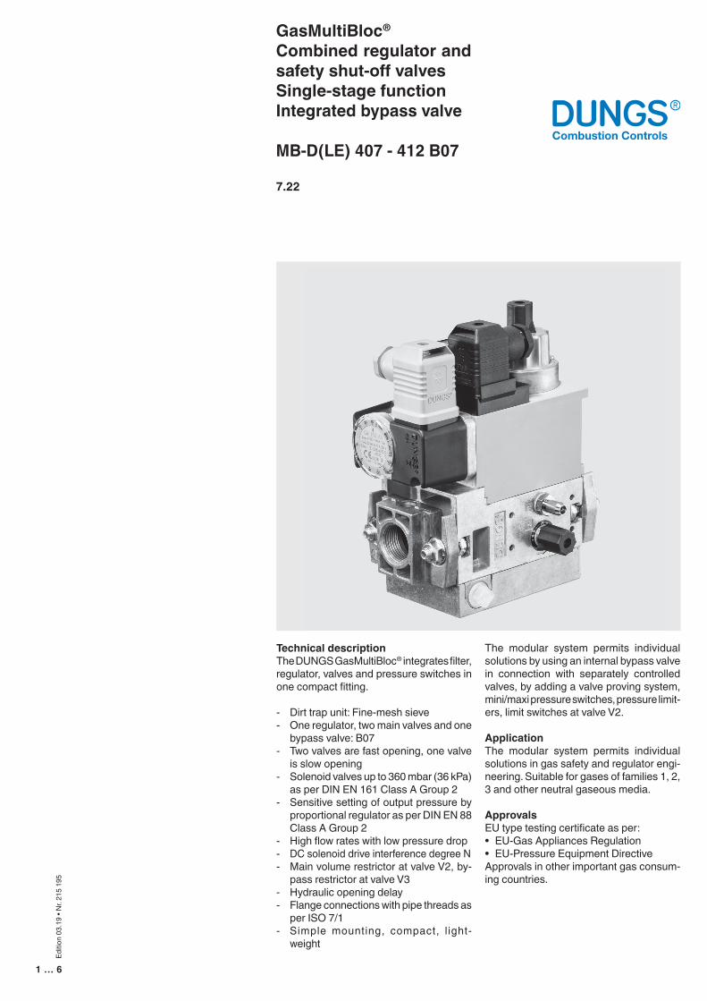
Technical descriptionThe DUNGS GasMultiBloc® integrates fi lter, regulator, valves and pressure switches in one compact fi tting.
- Dirt trap unit: Fine-mesh sieve- One regulator, two main valves and one
bypass valve: B07- Two valves are fast opening, one valve
is slow opening- Solenoid valves up to 360 mbar (36 kPa)
as per DIN EN 161 Class A Group 2- Sensitive setting of output pressure by
proportional regulator as per DIN EN 88 Class A Group 2
- High fl ow rates with low pressure drop- DC solenoid drive interference degree N- Main volume restrictor at valve V2, by-
pass restrictor at valve V3- Hydraulic opening delay- Flange connections with pipe threads as
per ISO 7/1- Simple mounting, compact, l ight-
weight
The modular system permits individual solutions by using an internal bypass valve in connection with separately controlled valves, by adding a valve proving system, mini/maxi pressure switches, pressure limit-ers, limit switches at valve V2.
ApplicationThe modular system permits individual solutions in gas safety and regulator engi-neering. Suitable for gases of families 1, 2, 3 and other neutral gaseous media.
ApprovalsEU type testing certifi cate as per: • EU-Gas Appliances Regulation• EU-Pressure Equipment DirectiveApprovals in other important gas consum-ing countries.
Editio
n 03
.19
• Nr.
215
195
2 … 6
Specifications
Nominal diametersFlange with pipe threads as per ISO 7/1 (DIN 2999)
Max. operating pressure
Output pressure ranges
Media
Ambient temperature
Dirt trap
Pressure switches
Pressure regulator
Solenoid valve V1
Solenoid valve V2
Solenoid valve V3 (bypass)
Measuring/ignition gas connection
Burner pressure monitor pBr
Voltage / frequency
Electrical connection
Rating/power consumptionSwitch-on durationDegree of protectionRadio interference
Materials of gas conveying parts
Installation position
Closed position signal contact
MB-…407 B07Rp 1/2, 3/4and their combinations
360 mbar (36 kPa)
MB-… S22 pa: 4 mbar (0.4 kPa) to 20 mbar (2 kPa)MB-… S52 pa: 4 mbar (0.4 kPa) to 50 mbar (5 kPa)
Gases of families 1, 2, 3 and other neutral gaseous media
-15 °C to +70 °C (Do not operate MB-D below 0 °C in liquid gas systems. Only suit-able for gaseous liquid gas, liquid hydrocarbons destroy sealing materials.)
Fine-mesh sieve. Replacement only possible by dismounting the fitting.
Types GW A5, GW A2, NB A2, ÜB A2 mountable as per DIN EN 1854.For further information, refer to Datasheet GW A2 No. 215 183 and Datasheet GW A5 No. 225 901.
Pressure regulator compensated for residual pressure, leakproof seal when switched off by means of valve V1 as per DIN EN 88 Class A. Setpoint spring permanently installed (no spring exchange possible). A vent line above roof is not required. Internal pulse tap provided.
Valve as per DIN EN 161 Class A Group 2, fast closing, fast opening
Valve as per DIN EN 161 Class A Group 2 Valve V2 design Main volume restrictor MB fast closing fast opening without MB-D fast closing fast opening with MB-DLE fast closing slow opening with MB-LE fast closing slow opening without
Valve as per DIN EN 161 Class A Group 2, with volume restrictor
For G 1/8 as per DIN ISO 228, refer to Pressure taps on page 4
Connection downstream of valve V2, pressure switch mountable on adapter laterally
50-60 Hz ,220 - 230 V AC, -15% +10%
Plug connection as per DIN EN 175301-803 for valves and pressure switches
Refer on page 4100%IP 54 as per IEC 529 (EN 60529)Interference degree N
Housing aluminium die castingDiaphragms, seals NBR basis, Silopren (silicone rubber)Solenoid drive steel, brass, aluminium
Solenoid vertically upright or lying horizontally as well as its intermediate posi-tions.
Closed position signal contact, type K01/1 (DIN-tested), mountable on V2
MB-…410/412 B07Rp 3/4, 1, 1 1/4and their combinations

3 … 6
407 B07
•••••
••••–•••••––
Equipment variantsGasMultiBloc®...B07Single-stage functionMBMB-DMB-DLEMB-LEMicrofilter (standard) with sieveGas pressure switchdownstream of filterdownstream of valve V2 on adapterPressure regulatorValve V1, double seatValve V2, single seatValve V2, double seatValve V3, single seat with restrictorValve opening separatelyFlange Rp 1/2 Rp 3/4 Rp 1 Rp 1 1/4
410 B07
•••••
•••••–••–•••
412 B07
•••••
••••–•••–•••
MB-...B07 version
V1 = Valve 1V2 = Valve 2V3 = Valve 33 = Filter4 = Pressure switch, optional5 = Regulator
Mounting of VPS 504 valve proving system possibleMounting of K01/1 closed position signal contact possible
• = possible(•) = on request - = not possible
S...2 version
1 = two A valves for main gas + regulator7 = two A valves for main gas, one A valve togetherwith V1 as internal bypass around V2 + regulator
0 = common2 = separated
2 = 4 - 20 mbar up to 360 mbar5 = 4 - 50 mbar up to 360 mbar
403 = DN 10, V2 = Single-seat valve405 = DN 15, V2 = Single-seat valve407 = DN 20, V2 = Double-seat valve410 = DN 25, V2 = Single-seat valve412 = DN 32, V2 = Double-seat valve415 = DN 40, V2 = Double-seat valve420 = DN 50, V2 = Double-seat valve
without = (MB or MB-ZR)-D = Main volume restrictor-LE = adjustable opening behaviour-DLE = D + LE combination
without = single stageZR = double-stage with partial volume settingfirst stage
Type key of MultiBloc®
31
V1 V2
V3
5
4

4 … 6
Weight [kg]
2,72,85,35,4
Type
MB-D 407 B07MB-DLE 407 B07MB-D 410 B07/412 B07MB-DLE 410 B07/412 B07
a
110 110 140 140
b
151151185185
c
40404040
g
104104120120
d
46 46 55 55
h
115 115 135 135
e
100 140 125 160
f
185 185 245 245
Nominal rating [VA]~(AC) 230 V; +20°C
S224646110110
Dimensions [mm]
c = Space requirement for cover of pressure switchf = Space requirement for exchanging the solenoid
Dimensions [mm]
abc
d
ef
g
h
Electrical connection
P1L1
P2L2
Mp N
MB-D(LE) B07
S22 / S52
P2L2
P1L1
MPN
1
23
Pressure taps
2
4 43
15 5
S524646110110
1, 4, 5 G 1/8 screw plug2 Test nipple3 Bypass throttle
3pe
4pa
1 5
4pa
V1 V2
V3
2
5 … 6
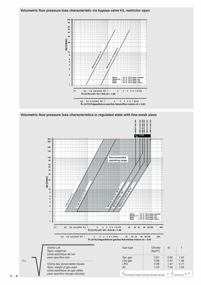
Volumetric flow pressure loss characteristic via bypass valve V3, restrictor open
∆p [m
bar]
Vn [m3/h] Luft / Air / Aria dv = 1,00°
2
3
456
1
810
20
30
40
60
80100
50
2 3 4 5 61 7 8 910
Basis + 15° C, 1013 mbar, trockenBased on + 15° C, 1013 mbar, dryBase + 15° C, 1013 mbar, secBase + 15° C, 1013 mbar, secco
0,1 0,2 0,3 0,4 0,5 0,6 0,8
2 3 4 5 61 7 8 9100,2 0,3 0,4 0,5 0,6 0,8
MB-
D(LE
) 410
/ 41
2 By
pass
V3
MB-
D(LE
) 407
Byp
ass V
3
Vn [m3/h] Erdgas/Natural gas/Gaz Naturel/Gas metano dv = 0,65°
Volumetric flow pressure loss characteristics in regulated state with fine-mesh sieve
Dichte LuftSpec. weight airpoids spécifique de l'airpeso specifico aria
Dichte des verwendeten GasesSpec. weight of gas usedpoids spécifique du gaz utilisépeso specifico del gas utilizzato
f =
Gas type
Nat. gasCity gasLPGAir
Density[kg/m3]
0.810.582.081.24
dv
0.650.471.671.00
f
1.241.460.771.00
Vverwendetes Gas/gas used/ gaz utilisé/gas utilizzato = ° °V Luft/air/air/aria x f
∆p [m
bar]
Vn [m3/h] Luft / Air / Aria dv = 1,00°
2
3
456
1
810
20
30
40
60
80100
50
2 3 4 5 61 7 8 910 20 30 40 60 80 100 200
Basis + 15° C, 1013 mbar, trockenBased on + 15° C, 1013 mbar, dryBase + 15° C, 1013 mbar, secBase + 15° C, 1013 mbar, secco
0,1 0,2 0,3 0,4 0,5 0,6 0,8
200
300360
150
MB-
412
S20,
S22
MB-
412
S50,
S52
MB-
410
S50,
S52
MB-
407
S50,
S52
MB-
410
S20,
S22
MB-
407
S20,
S22
MB-D(
LE) 4
07 R
p 3/
4 - R
p 3/
4
MB-D(
LE) 4
10 R
p 1 -
Rp
1
MB-D(
LE) 4
12 R
p 5/
4 - R
p 5/
4
V m
in. M
B-D(
LE) 4
07
V m
in. M
B-D(
LE) 4
10 / 4
12
p = 3 mbarBr
Vn [m3/h] Erdgas/Natural gas/Gaz Naturel/Gas metano dv = 0,65°2 3 4 5 61 7 8 910 20 30 40 60 80 100 2000,2 0,3 0,4 0,5 0,6 0,8
Recommended operating range

6 … 6
GasMultiBloc®
Combined regulator and safety shut-off valvesSingle-stage functionIntegrated bypass valve
MB-D(LE) 407 - 412 B07
We reserve the right to make any changes in the interest of technical progress.
Head Offices and FactoryKarl Dungs GmbH & Co. KGKarl-Dungs-Platz 1D-73660 Urbach, GermanyTelephone +49 (0)7181-804-0Fax +49 (0)7181-804-166
Postal addressKarl Dungs GmbH & Co. KGPostfach 12 29D-73602 Schorndorf, Germanye-mail [email protected] www.dungs.com