Gas Turbines- Ignition System
36
description
Gas Turbines- Ignition System
Transcript of Gas Turbines- Ignition System


Gas Turbines- Ignition system
Introduction
Subsystems and accessories are separate from the main gas turbine engine assembly.
This lecture presents information on three gas turbine engine subsystems and accessories:· ignition system· accessory drives (gearbox)· vibration monitoring system
Subsystems and accessories are essential for gas turbine engine operation.The first subsystem discussed is the ignition system.
Ignition System
Gas Turbines- Ignition system
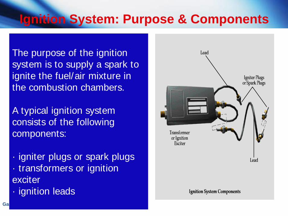
The purpose of the ignition system is to supply a spark to ignite the fuel/air mixture in the combustion chambers.
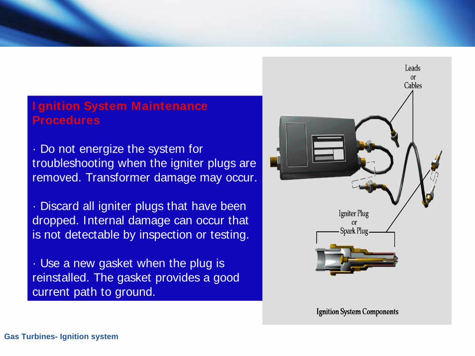
A typical ignition system consists of the following components:
· igniter plugs or spark plugs· transformers or ignition exciter· ignition leads
Ignition System: Purpose & Components

Gas Turbines- Ignition system
G.E. Ignition System Components (Contd. )
Ignition system components and operation differ among manufacturers. However, the purpose of the system is the same.
We will look at the components and operation of typical ignition systems used by General Electric (G.E.) and Solar.
We begin with the G.E. ignition system.
Gas Turbines- Ignition system
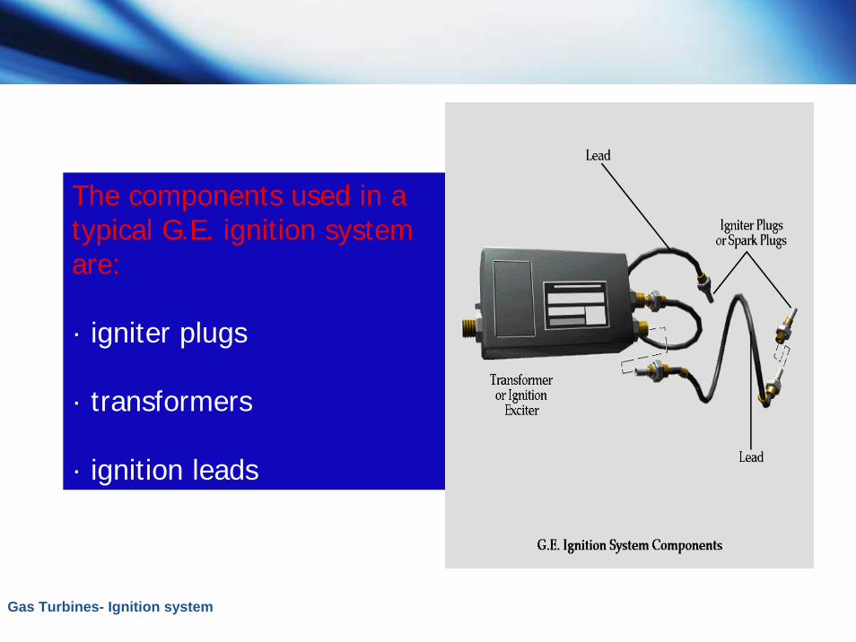
The components used in a typical G.E. ignition system are:
· igniter plugs
· transformers
· ignition leads
Gas Turbines- Ignition system
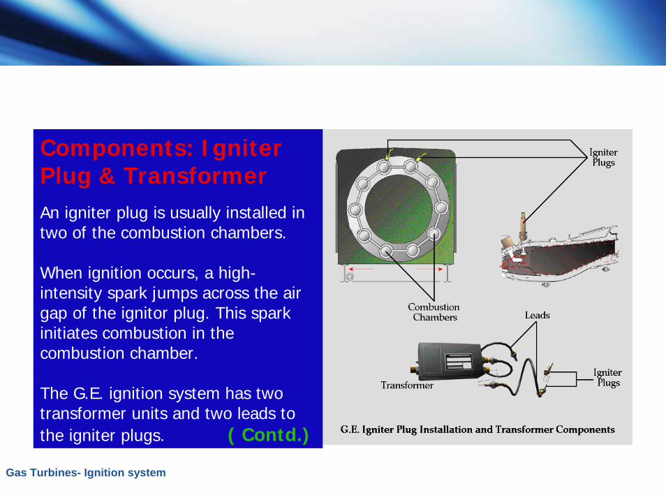
Components: Igniter Plug & TransformerAn igniter plug is usually installed in two of the combustion chambers.
When ignition occurs, a high-intensity spark jumps across the air gap of the ignitor plug. This spark initiates combustion in the combustion chamber.
The G.E. ignition system has two transformer units and two leads to the igniter plugs. ( Contd.)
Gas Turbines- Ignition system
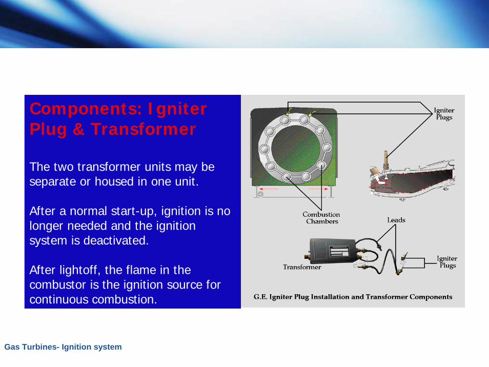
Components: Igniter Plug & Transformer
The two transformer units may be separate or housed in one unit.
After a normal start-up, ignition is no longer needed and the ignition system is deactivated.
After lightoff, the flame in the combustor is the ignition source for continuous combustion.
Gas Turbines- Ignition system
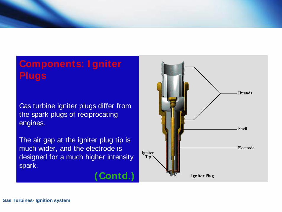
Components: Igniter Plugs
Gas turbine igniter plugs differ from the spark plugs of reciprocating engines.
The air gap at the igniter plug tip is much wider, and the electrode is designed for a much higher intensity spark.
(Contd.)
Gas Turbines- Ignition system
Components: Igniter Plugs
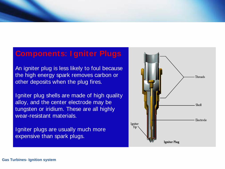
An igniter plug is less likely to foul because the high energy spark removes carbon or other deposits when the plug fires.
Igniter plug shells are made of high quality alloy, and the center electrode may be tungsten or iridium. These are all highly wear-resistant materials.
Igniter plugs are usually much more expensive than spark plugs.

Gas Turbines- Ignition system
Components: Igniter Plugs
The hot end of the igniter plug is usually air cooled to keep it 500°F to 600°F cooler than the gas temperature.
This cooler temperature helps to prevent corrosion.
Next we focus on the ignition system components used by Solar.
Gas Turbines- Ignition system
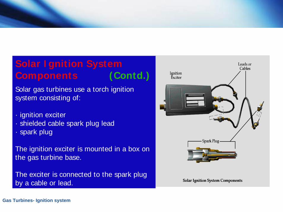
Solar Ignition System Components (Contd.)Solar gas turbines use a torch ignition system consisting of:
· ignition exciter· shielded cable spark plug lead· spark plug
The ignition exciter is mounted in a box on the gas turbine base.
The exciter is connected to the spark plug by a cable or lead.
Gas Turbines- Ignition system
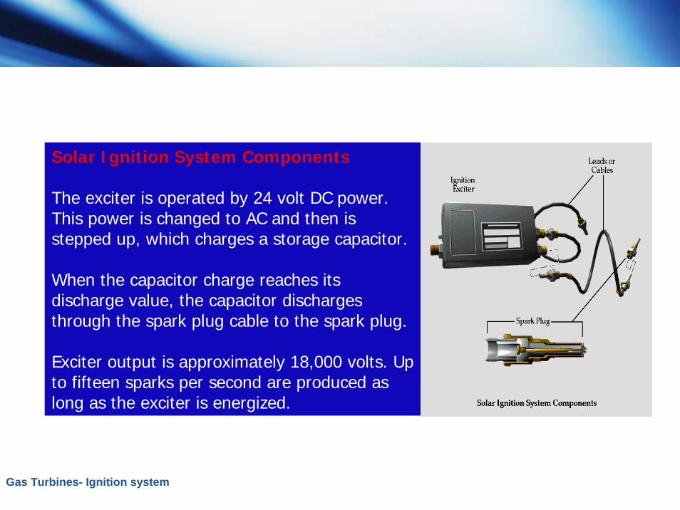
Solar Ignition System Components
The exciter is operated by 24 volt DC power. This power is changed to AC and then is stepped up, which charges a storage capacitor.
When the capacitor charge reaches its discharge value, the capacitor discharges through the spark plug cable to the spark plug.
Exciter output is approximately 18,000 volts. Up to fifteen sparks per second are produced as long as the exciter is energized.
Gas Turbines- Ignition system
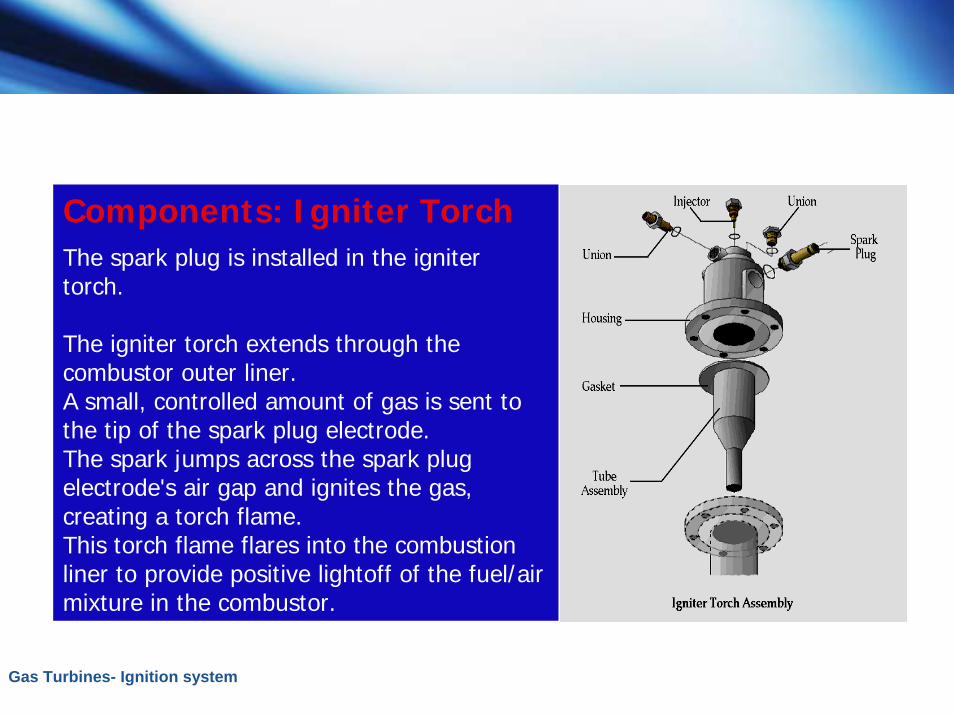
Components: Igniter TorchThe spark plug is installed in the igniter torch.
The igniter torch extends through the combustor outer liner.A small, controlled amount of gas is sent to the tip of the spark plug electrode.The spark jumps across the spark plug electrode's air gap and ignites the gas, creating a torch flame.This torch flame flares into the combustion liner to provide positive lightoff of the fuel/air mixture in the combustor.
Gas Turbines- Ignition system
Ignition System Maintenance Procedures (Contd.)
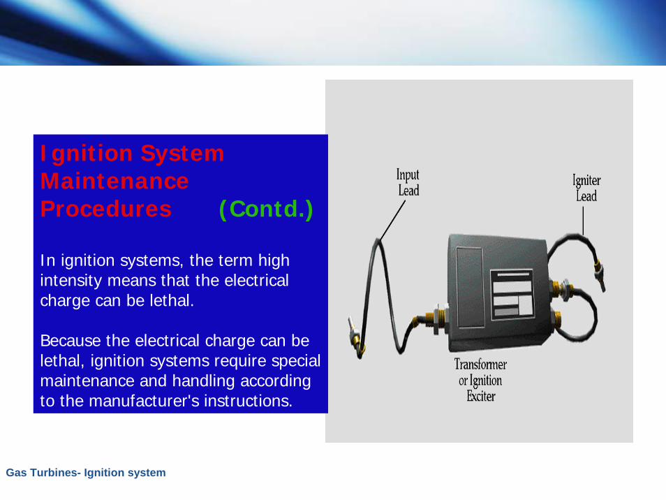
In ignition systems, the term high intensity means that the electrical charge can be lethal.
Because the electrical charge can be lethal, ignition systems require special maintenance and handling according to the manufacturer's instructions.
Gas Turbines- Ignition system
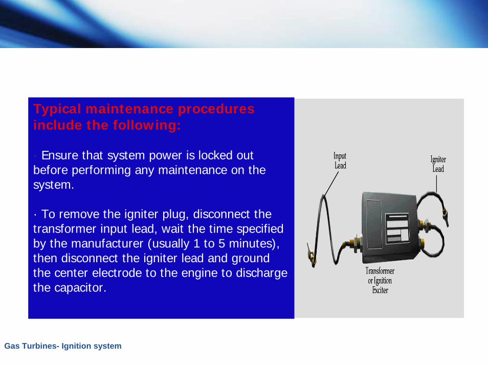
Typical maintenance procedures include the following:
· Ensure that system power is locked out before performing any maintenance on the system.
· To remove the igniter plug, disconnect the transformer input lead, wait the time specified by the manufacturer (usually 1 to 5 minutes), then disconnect the igniter lead and ground the center electrode to the engine to discharge the capacitor.
Gas Turbines- Ignition system
Ignition System Maintenance Procedures (Contd.)
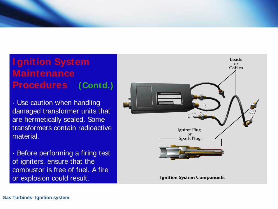
· Use caution when handling damaged transformer units that are hermetically sealed. Some transformers contain radioactive material.
· Before performing a firing test of igniters, ensure that the combustor is free of fuel. A fire or explosion could result.
Gas Turbines- Ignition system
Ignition System Maintenance Procedures
· Do not energize the system for troubleshooting when the igniter plugs are removed. Transformer damage may occur.
· Discard all igniter plugs that have been dropped. Internal damage can occur that is not detectable by inspection or testing.
· Use a new gasket when the plug is reinstalled. The gasket provides a good current path to ground.
Gas Turbines- Ignition system
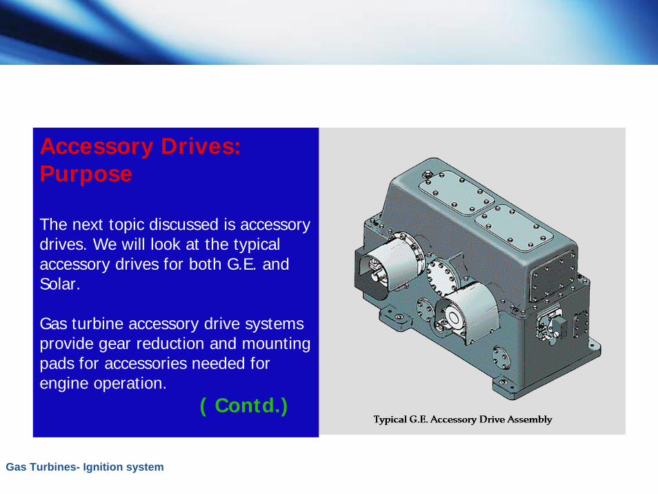
Accessory Drives: Purpose
The next topic discussed is accessory drives. We will look at the typical accessory drives for both G.E. and Solar.
Gas turbine accessory drive systems provide gear reduction and mounting pads for accessories needed for engine operation.
( Contd.)
Gas Turbines- Ignition system
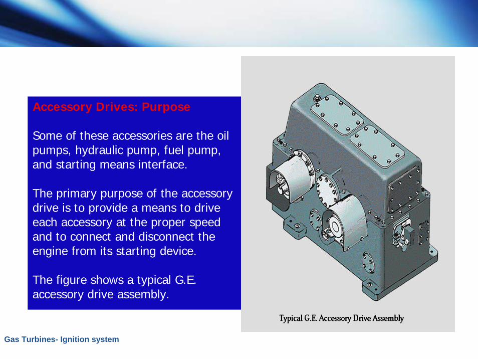
Accessory Drives: Purpose
Some of these accessories are the oil pumps, hydraulic pump, fuel pump, and starting means interface.
The primary purpose of the accessory drive is to provide a means to drive each accessory at the proper speed and to connect and disconnect the engine from its starting device.
The figure shows a typical G.E. accessory drive assembly.
Gas Turbines- Ignition system
G.E. Accessory DriveThe accessory drive gear is driven by a shaft that meshes with a helical gear driven by the main rotor shaft.
The gearbox is usually located at the front (forward) or the rear (aft) of the gas turbine engine, depending on the engine inlet or exhaust arrangements.
G.E. describes its typical accessory drive system as the main link between the gas turbine and the drive components of the starting system.

Gas Turbines- Ignition system
G.E. Accessory Drive: Function
The gear drives several accessory devices that support gas turbine operation.
Each drive pad is a point of potential oil leakage because of the shaft seal arrangement.
Engine oil from the lube oil pump or the hydraulic pump may leak into, or from, the accessory drive assembly through the drive shaft seal.
Gas Turbines- Ignition system
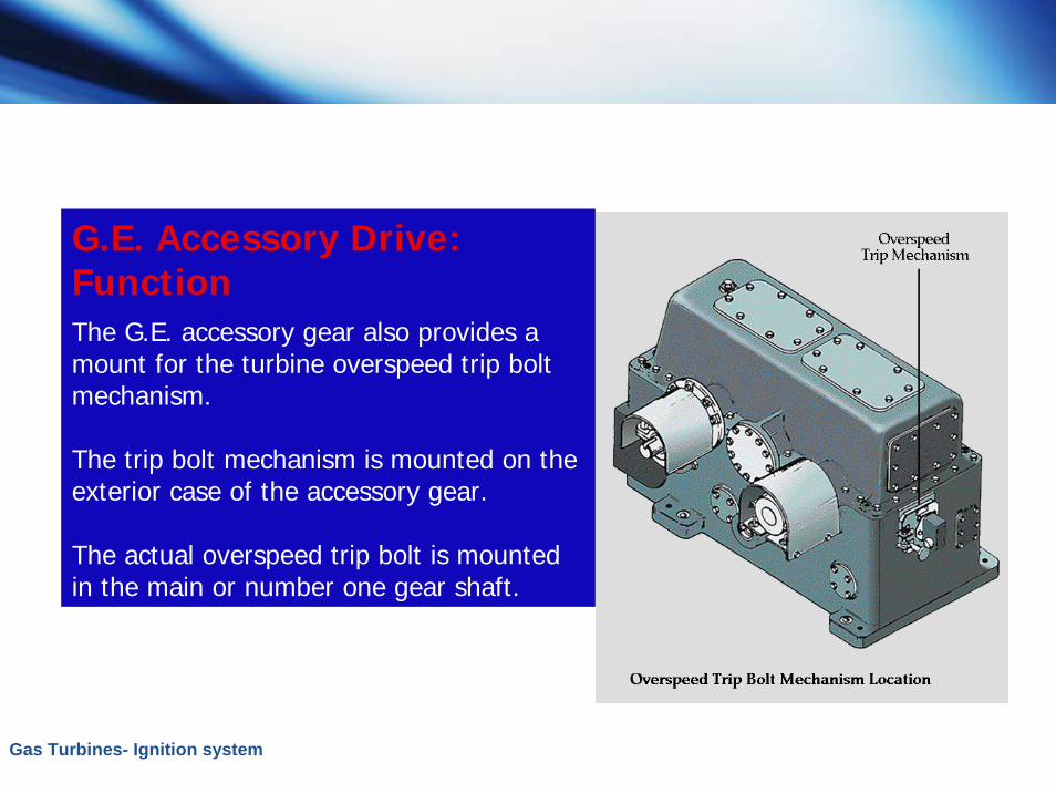
G.E. Accessory Drive: FunctionThe G.E. accessory gear also provides a mount for the turbine overspeed trip bolt mechanism.
The trip bolt mechanism is mounted on the exterior case of the accessory gear.
The actual overspeed trip bolt is mounted in the main or number one gear shaft.

Gas Turbines- Ignition system
Solar Accessory Drive: Function (Contd.)On Solar gas turbines, the accessory drive is attached to the air inlet assembly.
The accessory housing contains the accessory drive gears, pinion gears, and the necessary shafts and bearings.
Mounting pads and gear drives are provided for the starter, lube oil pump, hydraulic oil pump, speed governor, seal oil pump, and other accessories.

Gas Turbines- Ignition system
Solar Accessory Drive: Function
If a particular accessory is not used, a cover plate is installed on the mounting pad.
During the starting cycle, the Solar accessory gear is driven by the starter assembly.
Gas Turbines- Ignition system
Solar Accessory Drive: Function
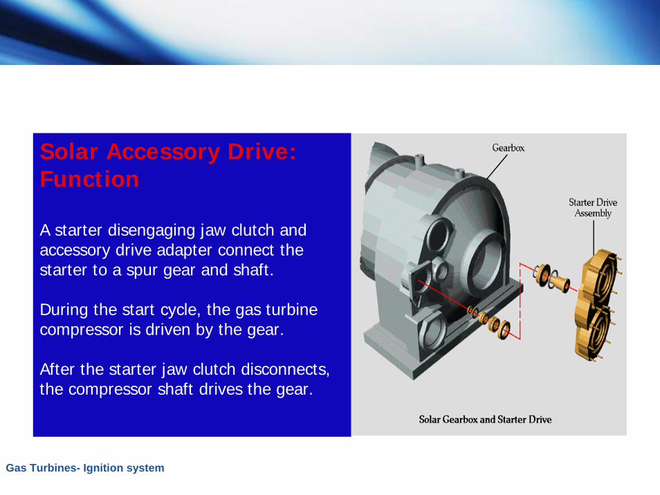
A starter disengaging jaw clutch and accessory drive adapter connect the starter to a spur gear and shaft.
During the start cycle, the gas turbine compressor is driven by the gear.
After the starter jaw clutch disconnects, the compressor shaft drives the gear.
Gas Turbines- Ignition system
Vibration Monitoring System: Purpose (Contd.)
The last topic discussed in this lesson is the vibration monitoring system. The purpose of the vibration monitoring system is to help in preventing abnormal operating conditions.
The rotating shafts of any machine or gearbox have a tendency to move axially or radially as a result of speed, loads, worn internal parts, unbalance, or other reasons.
Gas Turbines- Ignition system
Vibration Monitoring System: Purpose
Axial and radial shaft movement is called vibration. Vibration is a continuing periodic change in a displacement from a fixed reference.
Excessive vibration is an abnormal operating condition that can result in equipment damage. Excessive vibration is a symptom of other abnormal conditions.
A bent shaft or improper shaft alignment could be the source of vibration.
Gas Turbines- Ignition system
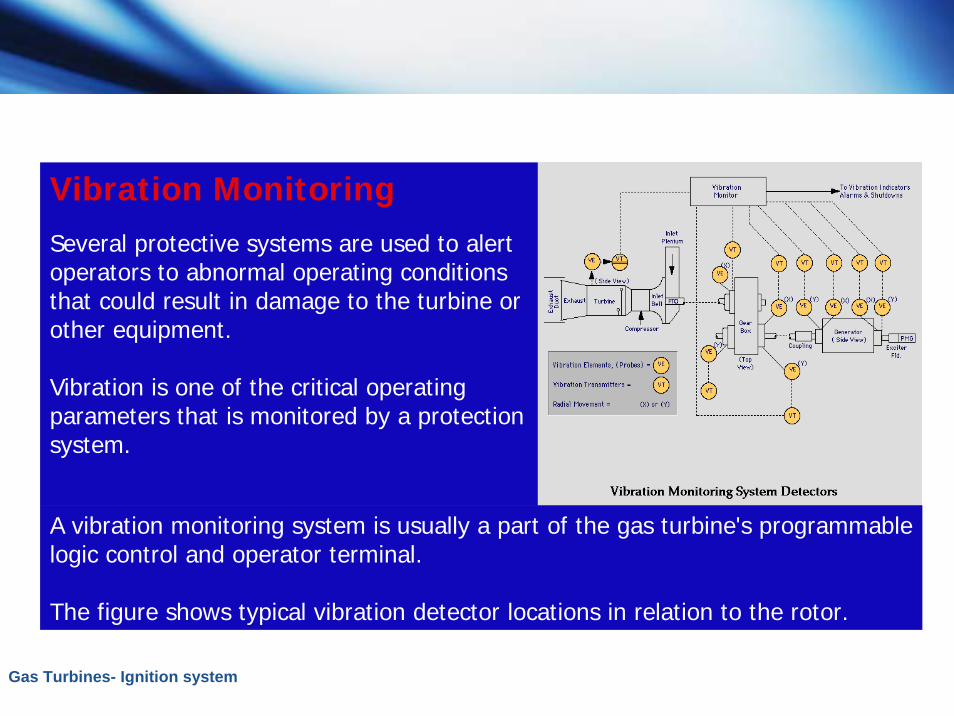
Vibration MonitoringSeveral protective systems are used to alert operators to abnormal operating conditions that could result in damage to the turbine or other equipment.
Vibration is one of the critical operating parameters that is monitored by a protection system.
A vibration monitoring system is usually a part of the gas turbine's programmable logic control and operator terminal.
The figure shows typical vibration detector locations in relation to the rotor.

Gas Turbines- Ignition system
Shaft Movement
Vibration monitoring systems are installed on gas turbines and driven equipment to monitor and sometimes record axial and radial shaft movement.
Shaft movement is monitored in either displacement (mils), velocity (length/unit-time), or acceleration (g's).
(Contd.)
Gas Turbines- Ignition system
One mil equals 0.001 of an inch. A shaft movement of 5 mils could generate an electrical impulse of one volt. Either of these measurements may be used as setpoints to initiate an alarm or shutdown.
Gas Turbines- Ignition system
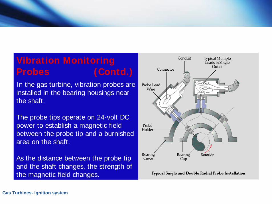
Vibration Monitoring Probes (Contd.)In the gas turbine, vibration probes are installed in the bearing housings near the shaft.
The probe tips operate on 24-volt DC power to establish a magnetic field between the probe tip and a burnished area on the shaft.
As the distance between the probe tip and the shaft changes, the strength of the magnetic field changes.
Gas Turbines- Ignition system
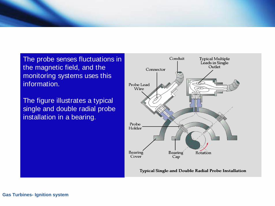
The probe senses fluctuations in the magnetic field, and the monitoring systems uses this information.
The figure illustrates a typical single and double radial probe installation in a bearing.
Gas Turbines- Ignition system
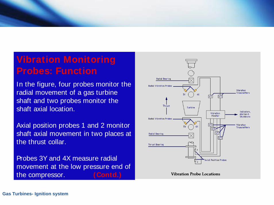
Vibration Monitoring Probes: FunctionIn the figure, four probes monitor the radial movement of a gas turbine shaft and two probes monitor the shaft axial location.
Axial position probes 1 and 2 monitor shaft axial movement in two places at the thrust collar.
Probes 3Y and 4X measure radial movement at the low pressure end of the compressor. (Contd.)
Gas Turbines- Ignition system
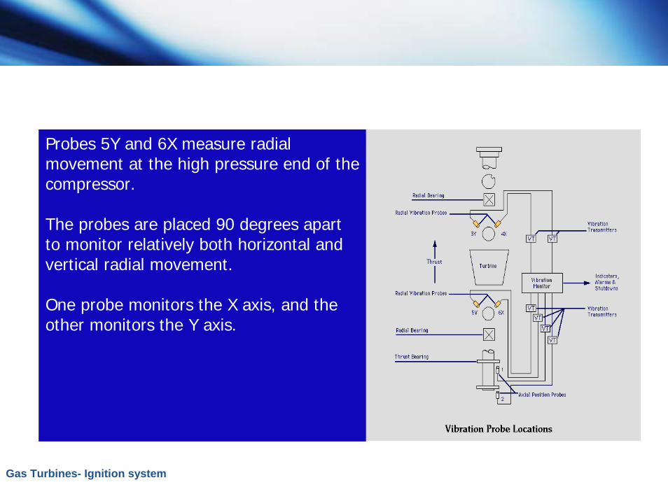
Probes 5Y and 6X measure radial movement at the high pressure end of the compressor.
The probes are placed 90 degrees apart to monitor relatively both horizontal and vertical radial movement.
One probe monitors the X axis, and the other monitors the Y axis.
Gas Turbines- Ignition system
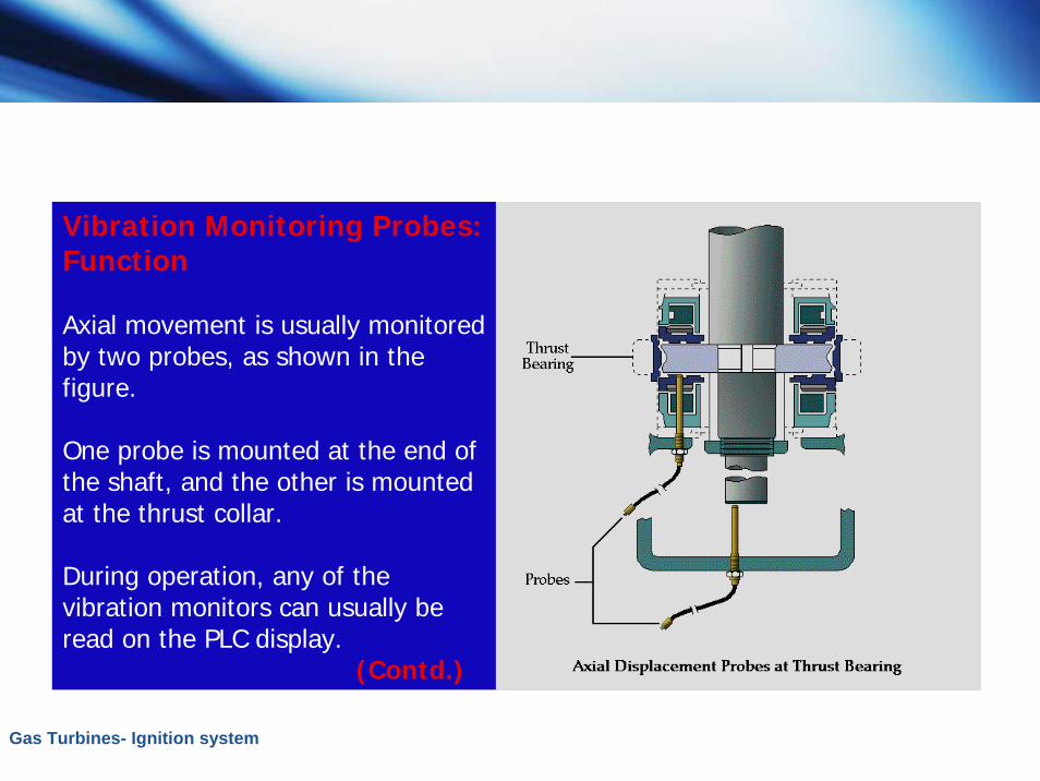
Vibration Monitoring Probes:Function
Axial movement is usually monitored by two probes, as shown in the figure.
One probe is mounted at the end of the shaft, and the other is mounted at the thrust collar.
During operation, any of the vibration monitors can usually be read on the PLC display.
(Contd.)
Gas Turbines- Ignition system
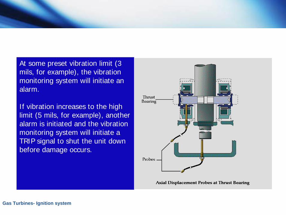
At some preset vibration limit (3 mils, for example), the vibration monitoring system will initiate an alarm.
If vibration increases to the high limit (5 mils, for example), another alarm is initiated and the vibration monitoring system will initiate a TRIP signal to shut the unit down before damage occurs.