GAS POWER SYSTEMS FUEL CAPABILITIES - ETN Global · GAS POWER SYSTEMS FUEL CAPABILITIES Jeffrey...
9
1 The Future of Gas Turbine Technology 8 th International Gas Turbine Conference 12-13 October 2016, Brussels, Belgium Paper ID Number (12-IGTC16) GAS POWER SYSTEMS FUEL CAPABILITIES Jeffrey Goldmeer, Ph.D. 1 , Michal Knapczyk 2 , Patrick Pastecki 3 1 GE Power, Gas Power Systems 1 River Road, 37-323 Schenectady, NY 12345, USA [email protected] 2 GE Power, Gas Power Systems Engineering Design Center Aleja Krakowska 110/114 02-256 Warsaw, Poland [email protected] 3 GE Power, Gas Power Systems 16415 Jacintoport Blvd. Houston, TX 77015, USA [email protected] ABSTRACT The functional objective of any power plant is to produce electricity at the lowest cost possible. This is primarily determined by the operational cost of the fuel consumed. Hence, it is paramount to end users that the energy infrastructure installed provides the greatest fuel flexibility with respect to the composition thresholds and rate of change limits. Drivers for this capability are the expertise, equipment, and experience provided by an OEM to advance the state of the art in gas turbine technologies. Plant value can be enhanced when gas turbines are capable of operating on alternative fuels that can have elevated levels of inert, heavier hydrocarbon content, or exhibit high variation in composition over a short duration. This is also true when gas turbines are capable of operating on a variety of lower cost liquid fuels. The purpose of this paper is to illustrate the current technology landscape and recent developments of GE’s Gas Power Systems gas turbine product portfolio, which includes both aeroderivative and heavy-duty gas turbines. It is through these recent developments that gas turbines present an opportunity to redefine the vertical integration into end user applications for power generation and mechanical drive. Fuel capability enables new applications of turbines in plant designs and access of new opportunities previously unobtainable. INTRODUCTION The process of choosing a fuel for electrical power generation is a complex task that is influenced by multiple factors including fuel price and availability, as well as government policy and regulation. Gas turbines, which are a key part of power generation globally, are capable of operating on a wide variety of gaseous and liquid fuels as described by Jones, et al. (2011), and Schornick, et al. (2013). Even though gas turbines have broad fuel flex capability, many power plant developers and owners select natural gas for power generation due to its availability and low emissions. However, what happens when the supply of natural gas is interrupted due to routine pipeline system maintenance, disturbances at the gas treatment facility, or natural disaster? A large number of power plants have back-up fuel capability to ensure continuous power generation, and for many plants, the back-up fuel of choice is distillate oil #2. Not all power producers want to burn distillate, which is a highly refined product that can be very costly. Instead, some power producers want to use low cost, locally available alternative liquid fuels for power generation. Since 1980 there have been more than 80 GW of awards for new power plants (over 35 MW in size) using non-traditional fuels. (In this paper, the terms non- traditional and alternative fuels are defined as fuels other than natural gas and distillate fuel oil #2.) These awards required more than 800 new gas turbines. As the portfolio of non-traditional or alternative power generation fuels expands, it is important to ensure that advanced, highly efficient gas turbines are able to operate on these fuels. This capability includes the ability to operate on an existing hydrocarbon gas or liquid that is being applied for the first time as a power generation fuel, or operating on an existing fuel with increased tolerance of variation in composition. The ability to operate on a wide range of fuels is not new, nor is the process of expanding the range of potential fuels. The development of these capabilities has been ongoing for decades. As part of this process of developing new combustion technology, GE draws on insights gleaned from more than 70 million fired hours on lean pre-mixed combustion systems, and more than 5 million fired hours operating on low BTU gases and liquid fuels. This field experience is combined with learnings from combustion testing in GE’s state of the art test facility to facilitate the development of new combustion systems, including both the gas turbine and required support systems.
Transcript of GAS POWER SYSTEMS FUEL CAPABILITIES - ETN Global · GAS POWER SYSTEMS FUEL CAPABILITIES Jeffrey...

1
The Future of Gas Turbine Technology
8th
International Gas Turbine Conference
12-13 October 2016, Brussels, Belgium
Paper ID Number (12-IGTC16)
GAS POWER SYSTEMS FUEL CAPABILITIES
Jeffrey Goldmeer, Ph.D. 1, Michal Knapczyk
2, Patrick Pastecki
3
1 GE Power, Gas Power Systems
1 River Road, 37-323
Schenectady, NY 12345, USA
2 GE Power, Gas Power Systems
Engineering Design Center
Aleja Krakowska 110/114
02-256 Warsaw, Poland
3 GE Power, Gas Power Systems
16415 Jacintoport Blvd.
Houston, TX 77015, USA
ABSTRACT
The functional objective of any power plant is to
produce electricity at the lowest cost possible. This is
primarily determined by the operational cost of the fuel
consumed. Hence, it is paramount to end users that the
energy infrastructure installed provides the greatest fuel
flexibility with respect to the composition thresholds and
rate of change limits. Drivers for this capability are the
expertise, equipment, and experience provided by an OEM
to advance the state of the art in gas turbine technologies.
Plant value can be enhanced when gas turbines are
capable of operating on alternative fuels that can have
elevated levels of inert, heavier hydrocarbon content, or
exhibit high variation in composition over a short duration.
This is also true when gas turbines are capable of operating
on a variety of lower cost liquid fuels.
The purpose of this paper is to illustrate the current
technology landscape and recent developments of GE’s
Gas Power Systems gas turbine product portfolio, which
includes both aeroderivative and heavy-duty gas turbines.
It is through these recent developments that gas turbines
present an opportunity to redefine the vertical integration
into end user applications for power generation and
mechanical drive. Fuel capability enables new
applications of turbines in plant designs and access of new
opportunities previously unobtainable.
INTRODUCTION The process of choosing a fuel for electrical power
generation is a complex task that is influenced by multiple
factors including fuel price and availability, as well as
government policy and regulation. Gas turbines, which are
a key part of power generation globally, are capable of
operating on a wide variety of gaseous and liquid fuels as
described by Jones, et al. (2011), and Schornick, et al.
(2013). Even though gas turbines have broad fuel flex
capability, many power plant developers and owners select
natural gas for power generation due to its availability and
low emissions. However, what happens when the supply
of natural gas is interrupted due to routine pipeline system
maintenance, disturbances at the gas treatment facility, or
natural disaster? A large number of power plants have
back-up fuel capability to ensure continuous power
generation, and for many plants, the back-up fuel of choice
is distillate oil #2. Not all power producers want to burn
distillate, which is a highly refined product that can be
very costly. Instead, some power producers want to use
low cost, locally available alternative liquid fuels for
power generation.
Since 1980 there have been more than 80 GW of
awards for new power plants (over 35 MW in size) using
non-traditional fuels. (In this paper, the terms non-
traditional and alternative fuels are defined as fuels other
than natural gas and distillate fuel oil #2.) These awards
required more than 800 new gas turbines.
As the portfolio of non-traditional or alternative power
generation fuels expands, it is important to ensure that
advanced, highly efficient gas turbines are able to operate
on these fuels. This capability includes the ability to
operate on an existing hydrocarbon gas or liquid that is
being applied for the first time as a power generation fuel,
or operating on an existing fuel with increased tolerance of
variation in composition.
The ability to operate on a wide range of fuels is not
new, nor is the process of expanding the range of potential
fuels. The development of these capabilities has been
ongoing for decades. As part of this process of developing
new combustion technology, GE draws on insights gleaned
from more than 70 million fired hours on lean pre-mixed
combustion systems, and more than 5 million fired hours
operating on low BTU gases and liquid fuels. This field
experience is combined with learnings from combustion
testing in GE’s state of the art test facility to facilitate the
development of new combustion systems, including both
the gas turbine and required support systems.

2
The power generation industry continues to request
that gas turbines be capable of operating on an ever
expanding variety of gas and liquid fuels. Although this is
a global phenomenon, alternative power generation fuels
tend to be locally generated, and therefore there can be
significant variation in the fuels that are seen globally.
Figure 1 shows power generation fuels of interest by
global region. An example of this is the use of crude oils
and other alternative liquid fuels in power plant projects in
Saudi Arabia. The Green Duba integrated solar combined
cycle (ISCC) project is planning to use a combination of
fuels (condensate, natural gas, and Arabian Super Light
crude oil) in a pair of F-class gas turbines.
A second example is the rising in interest in LPG and
ethane as power generation fuels. In the United States,
increased production of unconventional gases (which
includes shale gas) has caused ethane prices to be at or
near parity with natural gas and caused an equivalent drop
in LPG. The increased availability of ethane and LPG is
driving new infrastructure projects for transporting ethane
both domestically and internationally, creating the
potential for using ethane as a global feedstock or even as
a global power generational fuel potentially acting as a
replacement for LNG.
These examples highlight the ever changing
requirements of the power generation industry. To meet
these changes GE adapts current technology as well as
developing technology to provide solutions for new
challenges. This also includes the need to expand the fuel
capability of GE’s gas turbines. This paper will highlight
current fuel capability and provide insights into new fuel
capabilities.
NOMENCLATURE
AEV Advanced environment burner
ASL Arabian super light crude oil
AXL Arabian extra light crude oil
BFG Blast furnace gas
BTU British thermal unit
C2+ Hydrocarbon gas compounds heavier than
methane
CBM Coal bed methane
COG Coke oven gas
DO #2 Diesel oil #2
DLE Dry low emissions
DLN Dry low NOx
DME Dimethyl ether
EV Environmental burner
GC Gas chromatograph
H2 Hydrogen
HFO Heavy fuel oil
LHV Lower heating value
LNG Liquefied natural gas
LPG Liquefied petroleum gas
MWI Modified wobbe index
MGO Marine gas oil
NG Natural gas
NOx Oxides of Nitrogen (NO, NO2)
RCR Ramsbottom carbon residue
ROC Rate of change
T Temperature
GAS TURBINE FUEL CAPABILITY
GE’s gas turbines are capable of operating on a wide
variety of gas and liquid fuels. The graphic in Figure 2
highlights many of the fuels that can be used in
conjunction GE’s aeroderivative and/or heavy-duty gas
turbines. More details of gas turbine performance on
standard natural gas, as well as capabilities for ethane,
propane, hydrogen, and inerts are shown in Table 1.
Figure 2 - GE gas turbine fuel capabilities
This table presents the capability of the premixed
combustion system, typically referred as dry low emissions
(DLE) or dry low NOx (DLN) combustors. NOx emission
and turndown have been provided based on a standard
fuel, i.e. pipeline quality natural gas. For non-standard
fuels in general, an increase in amount of H2 and/or C2+
increases the NOx emissions, while increase in amount of
inerts decreases the NOx emissions. However, the
emissions capabilities on non-standard fuels will vary
based on project specific fuel composition as well as on
ambient conditions and site location.
Figure 1 - Regional power generation fuels

3
Additional rows provide an overview of nominal
wobbe variation (%). The maximum amounts of specific
components (by volume %) such as hydrogen, inerts, or
higher order hydrocarbons included are based either on
specification limits, validated values resulting from
combustor or full-scale gas turbine testing.
Table 1 – Nominal GE Gas Power Systems gas turbine (DLE/DLN) fuel capabilities
Note 1 - There are multiple configurations available for GE’s Aeroderivative gas turbines as well as the 13E2, and the values presented in
this table are representative of the capability of the specific gas turbine model. Actual performance and capability are site and fuel
specific.

4
GE’s aeroderivative and heavy-duty gas turbines can
also be configured with diffusion flame combustors. On
an aeroderivative gas turbine, this is the single annular
combustor (SAC). On heavy-duty gas turbines there are
two configurations, the single nozzle (SN) or standard
combustor, and the multi-nozzle quiet combustor
(MNQC). These combustors have much larger fuel
capabilities than DLE or DLN combustion systems,
including the capability to operate on synthesis gas
(syngas), high H2 fuels, and a variety of liquid fuels (i.e.
distillate, crude oil, heavy fuel oil). For example, GE’s
fleet leader on the use of high H2 fuels is 6B.03
(configured with a Standard Combustor) that has over
100,000 fired hours on a fuel with a hydrogen
concentration that varies from 85-95%. NOx emissions
from diffusion flames are much higher than from lean
premixed flames (i.e. DLE or DLN combustors) and are
mitigated through the use of diluent injection (i.e. water,
steam, nitrogen).
Although not addressed directly in this table, GE is
committed to continuing to expand the fuel capabilities of
its products. This also includes capabilities of burning non-
standard fuel that are challenging today or are yet
unknown and will emerge in the future. As these fuels
emerge, we explore them analytically and via in-depth test
campaigns of varying complexity to adjust or modify our
products.
Aeroderivative gas turbine fuel capability
GE’s Aeroderivative gas turbines are flexible and
reliable power generation packages with aviation derived
engines. The installed fleet has over 100 million operating
hours of experience, including operation on a variety of
power generation fuels as described by Knapczyk (2015),
including natural gas, distillate, kerosene, liquefied
petroleum gas (LPG), propane, synthetic gas (syngas),
coke oven gas and others shown in Figure 1. As
aeroderivative turbines are frequently used in industrial
applications, the ability to handle rapid fuel composition
changes in the fuel may be a critical requirement. The next
sections summarize this capability.
MWI Rate of Change
The ability of a gas turbine to maintain operability
during a change in fuel composition before the change is
fully measured and reported to the controls system
represents tolerance to fuel variability. This error tolerance
in LHV is a function of the combustion system, fuel
quality sensor, and the controls system capabilities. The
permissive LHV error tolerance can be found using the
ratio of the gas turbine error tolerance over the cumulative
instrument response time. This provides a time resolved
metric that defines acceptable or non-compliant changes in
gas fuel properties.
𝑅𝑎𝑡𝑒 𝑜𝑓 𝐶ℎ𝑎𝑛𝑔𝑒 [%
𝑠𝑒𝑐𝑜𝑛𝑑] =
𝑆𝑦𝑠𝑡𝑒𝑚 𝐸𝑟𝑟𝑜𝑟 𝑇𝑜𝑙𝑒𝑟𝑎𝑛𝑐𝑒 [%]
𝐼𝑛𝑠𝑡𝑟𝑢𝑚𝑒𝑛𝑡 𝑅𝑒𝑠𝑝𝑜𝑛𝑠𝑒 𝑇𝑖𝑚𝑒 [𝑠𝑒𝑐𝑜𝑛𝑑𝑠] (1)
The inertia of a gas turbine’s instantaneous operating
conditions results in limited tolerance to change in LHV,
especially without a known terminating point for a
transient. Excursions outside acceptable engineering
tolerances may manifest as unfavorable emissions,
acoustics, and the possible change or loss in power output
from the gas turbine.
An example of fuel variability is illustrated in Figure 3
in a three hour observation of the gas fuel heating value at
a customer site that is subject to periodic variation. The
black line represents the actual volumetric lower heating
value (Btu/scf). The light blue line represents a gas
chromatograph signal with cumulative response time of
180 seconds and corresponding value. The green and red
lines represent the upper and lower specification limit of
the ±0.5% and ±1.5% error tolerances, respectively.
Within this survey of gas properties there was a
transient event that occurred faster than the capability of
the gas chromatograph (GC) to measure and report the gas
fuel properties on a practical time scale. A smaller subset
of data during the disturbance is presented in Figure 4 to
illustrate the time periods of stable operation and the
transition into the potentially non-compliant operational
conditions as the fuel sensor signal lags to measure the
actual gas properties when they change rapidly.
Figure 3- Three hour gas survey from customer site
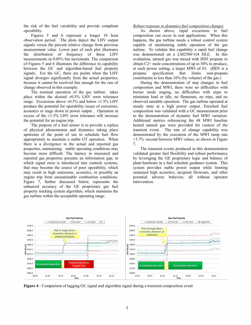
The left hand side of Figure 4 represents a transient
gas properties event in which the rate of change in the
baseline reference LHV measurement exceeds the assumed
gas chromatograph signal with the latency of three
minutes. The gas chromatograph cannot detect changes in
gas properties that are taking place within the response
time of the instrument, resulting in the potential for
imminent operability issues, if this sensor is the primary
guidance system for gas turbine fuel schedule. The right
hand side of Figure 4 represents the GE proprietary gas
fuel property tracking system algorithm’s ability to retire
5
the risk of the fuel variability and provide compliant
operability.
Figures 5 and 6 represent a longer 10 hour
observation period. The plots depict the LHV output
signals versus the percent relative change from previous
measurement value. Lower part of each plot illustrates
the distribution of frequency of these LHV
measurements in 0.05% bin increments. The comparison
of Figures 5 and 6 illustrates the difference in capability
between the GC and algorithm-based fuel property
signals. For the GC, there are points when the LHV
signal diverges significantly from the actual properties,
because it cannot be resolved fast enough for the rate of
change observed in this example.
The nominal operation of the gas turbine takes
place within the desired ±0.5% LHV error tolerance
range. Excursions above ±0.5% and below ±1.5% LHV
produce the potential for operability issues of emissions,
acoustics or stage down in power output . Operation in
excess of the ±1.5% LHV error tolerance will increase
the potential for an engine trip.
The purpose of a fuel sensor is to provide a replica
of physical phenomenon and dynamics taking place
upstream of the point of use to schedule fuel flow
appropriately to maintain a stable GT operation. When
there is a divergence in the actual and reported gas
properties, maintaining stable operating conditions may
become more difficult. The latency in measured and
reported gas properties presents an information gap, in
which signal error is introduced into controls systems,
that may become the source of poor operability, which
may result in high emissions, acoustics, or possibly an
engine trip from unsustainable combustion conditions.
Figure 7, further discussed below, represents the
enhanced accuracy of the GE proprietary gas fuel
property tracking system algorithm, which maintains the
gas turbine within the acceptable operating range.
Robust response to dynamics fuel composition changes
As shown above, rapid excursions in fuel
composition can occur in real applications. When this
happens, the gas turbine needs a robust control system
capable of maintaining stable operation of the gas
turbine. To validate this capability a rapid fuel change
was demonstrated on a LM2500+G4 DLE. In this
evaluation, natural gas was mixed with HD5 propane to
obtain C2+ mole concentrations of up to 50% to produce,
at each power setting, a target MWI of 63. (HD5 is a
propane specification that limits non-propane
constituents to less than 10% (by volume) of the gas.)
During the demonstration of step changes in fuel
composition and MWI, there were no difficulties with
burner mode staging, no difficulties with steps to
minimum load or idle, no flameouts, no trips, and no
observed unstable operation. The gas turbine operated at
steady state at a high power output. Enriched fuel
composition was validated with a GC measurement prior
to the demonstration of dynamic fuel MWI variation.
Additional metrics referencing the 48 MWI baseline
heated natural gas were provided for context of the
transient event. The rate of change capability was
demonstrated by the execution of the MWI ramp rate
>3.7% /second between MWI values, as shown in Figure
7.
The transient events produced in this demonstration
validated greater fuel flexibility and robust performance
by leveraging the GE proprietary logic and balance of
plant hardware in a fuel schedule guidance system. This
system provides stable power output while limiting
sustained high acoustics, incipient blowouts, and other
potential adverse behavior, all without operator
intervention.
Figure 4 - Comparison of lagging GC signal and algorithm signal during a transient composition event

6
Figure 5 - GC LHV resolved by percent change in adjacent measurements during the fuel survey
Figure 6 - Algorithm produced LHV resolved by the percent change in adjacent measurements during the fuel survey

7
Heavy-duty gas turbine fuel capability
GE’s heavy duty gas turbines platform includes E, F
and H-class products. GE introduced F-class technology
nearly 30 years ago and has the world’s largest fleet, with
more than 1,100 installed units, and 50 million operating
hours of experience. The E-class turbines are rugged even
in harsh climates with the capability to operate on a wide
variety of alternative gas and liquid fuels. The installed
fleet includes more than 3,000 units and more than 143
million operating hours of experience.
Over the last few years, there have been shifts in large
utility scale power generation and the need to burn
alternative fuels. One example is the need to operate F-
class gas turbines with DLN combustors on crude oil, and
the ability for large frame gas turbines to operate on fuels
with shifts in heating value.
Non-methane hydrocarbon capability
GE’s heavy-duty gas turbines are capable of operating
on a variety of fuels, including fuels with significant non-
methane hydrocarbon content. This capability can be
segmented into two categories: blending of hydrocarbons,
and pure (hydrocarbon) fuels.
GE’s B and E-class turbines are capable of operating
on a range of gaseous fuels, including ethane and propane.
Ethane, propane or LPG can be used either blended with
natural gas or as single fuel in a DLN1 or DLN1+
combustion system. GE’s F-class turbines can operate a
blend or 100% ethane. The 6F.01 and 6F.03 with DLN2.5
and DLN 2.6 combustors, respectively, can operate with a
blend of these fuels and natural gas, up to 15% non-
methane on the 6F.03 and 25% ethane on the 6F.01. The
7F.05 and 9F.04 gas turbines configured with the DLN2.6+
combustion system can operate with a blend up to 25%
ethane. For these gas turbines, operating with 100%
ethane (or other hydrocarbon) requires a MNQC
combustor. This capability exists for both new units and
units in the field. Existing units may require updates
and/or configuration changes for combustion and fuel
accessories as well as controls. In addition, the 7HA and
9HA gas turbines configured with the DLN2.6+
combustion system are capable of operating on ethane
blends.
GE has experience blending fuels in a variety of
applications. An example is a petrochemical plant that had
excess hydrogen, which was blended into natural gas and
used with a set of 7F.03 gas turbines configured with the
DLN2.6 combustion system as described by Goldmeer and
Rojas (2012). For this application, GE provided advanced
controls and the fuel blending system, including the
blending hardware, which is shown in Figure 8.
Figure 7 - Operation at > 3.7% MWI/second rate of change on a LM2500+G4 DLE using
blended natural gas and HD5 propane

8
Figure 8 - Fuel blending system hardware
Use of crude oil on F-class gas turbines
Arabian Super Light (ASL) crude oil is a stabilized
crude oil that was being considered for use as back-up fuel
for advanced F-class gas turbines (configured with DLN
combustion systems) in Saudi Arabia. To determine if this
oil would be a viable fuel for use with DLN combustion
systems, a detailed fuel evaluation procedure was followed
as described by Goldmeer (2014). This evaluation
included detailed analytical characterization of ASL,
combustion test, and culminated with field operation.
Details of the evaluation are provided by Goldmeer, at al.
(2015), and Goldmeer at al. (2014).
The results of a comparison to distillate are shown in
Table 2; note that many properties are the same. The most
significant difference in this data was the carbon residue.
The ramsbottom carbon residue (RCR) is determined by
taking a fuel sample of a given weight and heating at high
temperatures until nothing but solid carbon remains. The
reported RCR value is the percentage of the final weight of
the solid carbon to the weight of the original liquid fuel
sample. This parameter is an indicator of a fuel’s
propensity to form carbon-rich deposits, often referred to
simply as “coke”.
The evaluation of ASL required multiple steps,
including ignition studies and full pressure, full
temperature single nozzle combustion testing. The ignition
testing evaluated the ability of ASL to ignite in an
atmospheric test facility. (As ASL is a true crude oil, it had
a broader distillation curve, with the potential for increased
volatility.) A picture of the ASL flame from the ignition
study is shown in Figure 9. The single nozzle combustion
testing yielded a large set of data which showed that ASL
is very similar to distillate. As an example, figure 10
shows non-dimensional NOx and CO emissions from ASL
compared to distillate; note that the ASL and distillate
emissions were very similar. The same trend was found
when comparing combustion dynamics and combustion
liner temperatures.
Table 2 – Comparison of ASL crude oil and distillate PROPERTIES Unit ASL Distillate
Heating value (Gross)
BTU/lbm 19329 19420
Density g/cc 0.778 0.83
Viscosity @ 37.7 C (100F)
cSt 1.76 2.6
Carbon Weight % 86.36 85
Hydrogen (calculated)
Weight % 13.6 13
Ash ppm (mass) 3 100
Ramsbottom carbon residue
Weight % 0.32 0.035
Figure 10 - Comparison of ASL and distillate emissions
The next step in the process was a field evaluation of ASL.
This was performed at the Riyadh PP11 power plant in
Saudi Arabia. The plant is shown in Figure 11. In the
first phase of the demonstration, the gas turbine was fired
on ASL at part load (~38% of base load) for roughly 22
hours. In the second part of the test, the gas turbine was
operated on ASL at base load. The seven gas turbines at
Figure 9 - ASL flame

9
this site have since been fully commissioned on ASL and
are in commercial operation. Including this plant, GE has
been awarded 33 F-class gas turbines in Saudi Arabia that
will use ASL as back-up fuel, including Riyadh Power
Plant 12, which has commissioned it’s eight GE 7F.05 gas
turbines on ASL.
SUMMARY
Robust operation and flexibility are key requirements
for power generation applications. The ability of a gas
turbine to operate on a wide variety of fuels provides a
path to change the feasibility and economics of potential
opportunities. Shifts in fuel availability and economics
have driven some power generators to look at new fuels, or
fuels that would not have been considered in the past.
GE’s aeroderivative and heavy-duty gas turbines are
capable of operating on a wide variety of fuels, and can
provide robust operability for power generation in a
variety of applications.
REFERENCES Jones, R., Goldmeer, J., Monetti, B., 2011, “Addressing
Gas Turbine Fuel Flexibility”, GER4601B, GE Power &
Water.
Goldmeer, J., Rojas, T., 2012, “Burning a mixture of H2
and natural gas” Turbomachinery International, Jan/Feb
2012, p. 24.
Goldmeer, J., 2014, “Gas Turbine fuel evaluation process:
A case study on the application of Arabian Super Light
Crude oil for use in GE 7F-class Dry Low NOx (DLN)
combustion systems”, Power Gen International, Pennwell.
Goldmeer, J., Kihara, K., Fujimoto, H., 2015, “Recent
advancements in gas turbine fuel flexibility”, International
Gas Turbine Congress 2015, Tokyo, Japan, paper 210.
Goldmeer, J., Symonds, R., et al, 2014, “Evaluation of
Arabian Super Light Crude Oil for use in a F-class DLN
Combustion System”, ASME TurboExpo, GT2014-25351.
Knapczyk, M., 2015, “GE’s Aeroderivative Gas Turbines
Fuel Flexibility for Japan”, International Gas Turbine
Congress 2015, Tokyo, Japan.
Schornick, J, Knapczyk, M., Pastecki, P., DiCampli, J.,
2013, “Aeroderivative Gas Turbine Fuel Flexibility”,
PowerGen Asia, Pennwell.
Figure 11 - Riyadh PP11 combined cycle power plant