GAS-LIQUID SLUG FREQUENCY AND SLUG UNIT...
15
The Iraqi Journal For Mechanical And Material Engineering, Vol.15, No3, 2015 166 GAS-LIQUID SLUG FREQUENCY AND SLUG UNIT LENGTH IN HORIZONTAL PIPES Dr. Esam M. Abed 1 Zainab K. Gheben 2 . Department of Mechanical Engineering, Babylon University, Iraq. 1 [email protected] ABSTRACT The object of this work is to gain insight into gas-liquid slug flow frequency and the slug unit lengths in horizontal circular transparent pipe of 25.4mm inner diameter and 6m length, experiments done at atmospheric condition with air and water as the working fluids. The superficial gas velocity ranged from 3.947 m/s to 6.579 m/s with superficial liquid velocity around 0.986 m/s and 1.974 m/s. The effects of superficial gas velocity, superficial liquid velocity on slug frequency and slug unit lengths were taken into account. However, the essentials of the problem involve the determination of the slug frequency and slug unit length.In this experimental work a video camera system with image processing technique by MATLAB were used to extract the slug frequency and the slug unit lengths, which contain slug body length and Taylor bubble length or film region length. New data for slug frequency and slug unit lengths were found which achieved good agreements with the previous works. ﺍﻟﺴﺎﺋﻞ ﺗﺮﺩﺩ ﺍﻟﻤﻮﺟﺔ ﻭﻭﺣﺪﺓ ﻁﻮﻝ ﺍﻟﻤﻮﺟﺔ ﺑﺎﻻﻧﺎ- ﺍﻟﻐﺎﺯ ﺑﻴﺐ ﺍﻻﻓﻘﻴﺔ ﺯﻳﻨﺐ ﻛﺮﻳﻢ ﻏﺒﻦﻋﺼﺎﻡ ﻣﺠﺒﻞ ﻋﺒﺪ. ﺩ ﺟﺎﻣﻌﺔ ﺑﺎﺑﻞ، ﻛﻠﻴﺔ ﺍﻟﻬﻨﺪﺳﺔ، ﻗﺴﻢ ﺍﻟﻬﻨﺪﺳﺔ ﺍﻟﻤﻴﻜﺎﻧﻴﻜﻴﺔ ﺍﻟﺨﻼﺻﺔﺳﺎﺋﻞ ﻓﻲ- ﺍﻟﻬﺪﻑ ﻣﻦ ﺍﻟﻌﻤﻞ ﺍﻟﺤﺎﻟﻲ ﻫﻮ ﺗﺴﻠﻴﻂ ﺍﻟﻀﻮء ﻋﻠﻰ ﺩﺭﺍﺳﺔ ﺍﻟﺠﺮﻳﺎﻥ ﺛﻨﺎﺋﻲ ﺍﻟﻄﻮﺭ ﻟﺠﺮﻳﺎﻥ ﻣﺘﻘﻄﻊ ﻟﻤﺎﺋﻌﻴﻦ ﻏﺎﺯ ﺃﻧﺒﻮﺏ ﺍﻓﻘﻲ ﺷﻔﺎﻑ ﺑﻘﻄﺮ ﺩﺍﺧﻠﻲ25,4 ﻣﻠﻢ ﻭ ﻁﻮﻝ6 ﺳﺎﺋﻞ ﻭﻫﻜﺬﺍ، ﺗﻢ ﺩﺭﺍﺳﺔ-ﻏﺎﺯ- ﻡ،ﺣﻴﺚ ﺍﻥ ﺍﻟﺠﺮﻳﺎﻥ ﻳﻜﻮﻥ ﺑﺎﻟﺘﻌﺎﻗﺐ ﺳﺎﺋﻞ ﻁﻮﻝ ﺍﻟﻤﺴﺎﻓﺔ ﺍﻟﺘﻲ ﻳﺴﺘﻤﺮ ﻅﻬﻮﺭ ﺍﻟﺴﺎﺋﻞ ﻓﻴﻬﺎ ﻭ ﻛﺬﻟﻚ ﻁﻮﻝ ﻣﺴﺎﻓﺔ ﻅﻬﻮﺭ ﻁﻮﺭ ﺍﻟﻐﺎﺯ ﻭ ﺍﻟﺬﻳﻦ ﻳﻤﺜﻼﻥ ﻣﻌﺎ ﻁﻮﻝ ﻭﺣﺪﺓ ﺍﻟﺠﺮﻳﺎﻥ ﺑﺎﻹﺿﺎﻓﺔ ﺍﻟﻰ ﺫﻟﻚ ﺗﻢ ﺩﺭﺍﺳﺔ ﺗﺮﺩﺩ ﻫﺬﻩ ﺍﻟﻮﺣﺪﺓ، ﻟﻘﺪ ﺃﺟﺮﻳﺖ ﺍﻟﺘﺠﺎﺭﺏ ﺗﺤﺖ ﺍﻟﻈﺮﻭﻑ ﺍﻟﺒﻴﺌﻴﺔ ﺍﻟﻄﺒﻴﻌﻴﺔ ﻓﻲ ﺍﻟﻤﺨﺘﺒﺮ) ﻣﻌﺪﻝ ﺍﻟﺴﺮﻉ ﺍﻟﺨﺎﺭﺟﻴﺔ ﻟﻠﻄﻮﺭﻳﻦ ﺣﺪﺩﺕ ﻟﻠﻐﺎﺯ ﻣﻦ. ﺑﺎﺳﺘﺨﺪﺍﻡ ﺍﻟﻬﻮﺍء ﻛﻄﻮﺭ ﻏﺎﺯ ﻭ ﺍﻟﻤﺎء ﻛﻄﻮﺭ ﺳﺎﺋﻞ3,947 ﻡ/ - ﺛﺎ6,579 ﻡ/ ) ﻭ ﻟﻠﺴﺎﺋﻞ ﻣﻦ( ﺛﺎ0,986 ﻡ/ - ﺛﺎ1,974 ﻡ/ ﺗﻢ. ﻭ ﻗﺪ ﺗﻢ ﺩﺭﺍﺳﺔ ﺗﺄﺛﻴﺮﻫﺎ ﻋﻠﻰ ﻁﻮﻝ ﻭﺣﺪﺓ ﺍﻟﺠﺮﻳﺎﻥ ﻭﺗﺮﺩﺩ ﻫﺬﻩ ﺍﻟﻮﺣﺪﺓ( ﺛﺎ ﺍﺳﺘﺨﺪﺍﻡ ﻧﻈﺎﻡ ﺗﺼﻮﻳﺮ ﻓﻴﺪﻭﻱ ﻣﻊ ﺗﻘﻨﻴﺔ ﺍﻟﻤﻌﺎﻟﺠﺔ ﺍﻟﺼﻮﺭﻳﺔ ﺑﺎﺳﺘﺨﺪﺍﻡ ﺑﺮﻧﺎﻣﺞMATLAB ﺗﻢ ﺍﻟﺤﺼﻮﻝ ﻋﻠﻰ ﺑﻴﺎﻧﺎﺕ ﺟﺪﻳﺪﺓ. . ﺗﺘﻮﺍﻓﻖ ﻣﻊ ﻣﺎ ﺃﻭﺟﺪﻩ ﺍﻟﺒﺎﺣﺜﻮﻥ ﺳﺎﺑﻘﺎKEY WORDS Gas-liquid, slug, image processing, frequency, air-water, slug unit length.
Transcript of GAS-LIQUID SLUG FREQUENCY AND SLUG UNIT...

The Iraqi Journal For Mechanical And Material Engineering, Vol.15, No3, 2015
166
GAS-LIQUID SLUG FREQUENCY AND SLUG UNIT
LENGTH IN HORIZONTAL PIPES
Dr. Esam M. Abed1 Zainab K. Gheben2. Department of Mechanical Engineering, Babylon University, Iraq.
1
ABSTRACT
The object of this work is to gain insight into gas-liquid slug flow frequency and the slug unit lengths in horizontal circular transparent pipe of 25.4mm inner diameter and 6m length, experiments done at atmospheric condition with air and water as the working fluids. The superficial gas velocity ranged from 3.947 m/s to 6.579 m/s with superficial liquid velocity around 0.986 m/s and 1.974 m/s. The effects of superficial gas velocity, superficial liquid velocity on slug frequency and slug unit lengths were taken into account. However, the essentials of the problem involve the determination of the slug frequency and slug unit length.In this experimental work a video camera system with image processing technique by MATLAB were used to extract the slug frequency and the slug unit lengths, which contain slug body length and Taylor bubble length or film region length. New data for slug frequency and slug unit lengths were found which achieved good agreements with the previous works.
االفقيةبيبالغاز-السائل تردد الموجة ووحدة طول الموجة باالنا د.عصام مجبل عبد زينب كريم غبن
جامعة بابل، كلية الهندسة، قسم الهندسة الميكانيكية
الخالصة الهدف من العمل الحالي هو تسليط الضوء على دراسة الجريان ثنائي الطور لجريان متقطع لمائعين غاز-سائل في
م،حيث ان الجريان يكون بالتعاقب سائل-غاز-سائل وهكذا، تم دراسة 6 ملم و طول 25,4أنبوب افقي شفاف بقطر داخلي طول المسافة التي يستمر ظهور السائل فيها و كذلك طول مسافة ظهور طور الغاز و الذين يمثالن معا طول وحدة
الجريان باإلضافة الى ذلك تم دراسة تردد هذه الوحدة، لقد أجريت التجارب تحت الظروف البيئية الطبيعية في المختبر ثا-/م3,947باستخدام الهواء كطور غاز و الماء كطور سائل.معدل السرع الخارجية للطورين حددت للغاز من (
ثا) و قد تم دراسة تأثيرها على طول وحدة الجريان وتردد هذه الوحدة.تم /م1,974ثا-/م0,986ثا) و للسائل من (/م6,579. تم الحصول على بيانات جديدة MATLABاستخدام نظام تصوير فيدوي مع تقنية المعالجة الصورية باستخدام برنامج
تتوافق مع ما أوجده الباحثون سابقا.
KEY WORDS
Gas-liquid, slug, image processing, frequency, air-water, slug unit length.

Dr. Esam M. The Iraqi Journal For Mechanical And Material Engineering, Vol.15, No3, 2015
167
NOMENCLATURE
uL : Slug unit length (m). sL : Slug body length (m). fL : Film region length (m)
uLN : Number of slug units. inL : Distance from pipe entry (m). n : Period of time (s).
D : Pipe diameter (m). sf : Slug frequency (slug/s). t : Time (s).
β : Inclination angle. rearfronttailnose xxxx ,,, : Nose, tail, front and rear horizontal positions (m).
LU : Liquid superficial velocity (m/s). GU : Gas superficial velocity (m/s).
INTRODUCTION
Gas–liquid two-phase Slug flow occurs frequently in many industry fields. It is found in many applications like the distillation processes, steam generators, crude oil transportation and numerous chemical industrial processes. The slug flow pattern exists over a wide range of liquid and gas flow rates. It is characterized by a sequence of elongated bubbles separated by liquid slugs that may contain small bubbles. A comprehensive physical model describing horizontal gas-liquid slug flow was first initiated by Dukler and Hubbard (1975), as shown in Figure 1 .The length of slugs to be expected under intermittent flow conditions is important for the pipeline designer, the statistical distribution of slug lengths and the maximum likely slug length are important in the design of processing equipment and slug catchers as they must be capable of handling the range of slug lengths that can be produced Cook, 2000.
Assuming synthesize of one slug unit is divided into two regions the liquid slug region, also called slug body, and the liquid film region, consisting of a liquid film and an elongated Taylor gas bubble. The slug unit length is defined as Dukler and Hubbard (1975):
fsu LLL += (1)
Scott et al. (1989), empirical correlation based on data from the Prudhoe Bay field as:
}}]0254.0
[ln5.288.26exp{,30max{ 1.0DDLs +−= (2)
For pipe diameters of 0.0254m, Scott’s equation indicates that the average slug length is somewhere in the order of 30D. Dukler and Hubbard (1975), found for air-water, 38.1mmdiameter, mean slug body length ranging around 12D-30D. Nicholson et al. (1978) and Gregory et al. (1978), found for air-light oil, 25.8mm and 51.2mm diameters, nearly 30D. Nydal et al. (1992), found for air-water, 53mm diameter, range of 15D-20D, while for 90mm diameter found range of 12D-16D. Al-Safran (2009) has developed an empirical correlation which also accounts for stochastic variation in slug lengths. Magalhaes, et al. (2013) investigates the effects of gas solubility on the fluid dynamic properties of a horizontal two-phase slug flow through two optical techniques Shadow Sizer (SS) and Particle Image Velocimetry (PIV). In the experiments, a reduction of 4% in Lf resulted in a reduction of

GAS-LIQUID SLUG FREQUENCY AND SLUG Dr. Esam M. Abed UNIT LENGTH IN HORIZONTAL PIPES Zainab K. Gheben.
168
11.5% in dP/dx. In the simulations, a reduction of 6% in Lf resulted in a reduction of 4% in dP/dx. A decrease in Lf provokes a decrease in both the pressure drop due to friction across the slug and the pressure drop due to acceleration. In the numerical simulations, and over the considered length, these two effects resulted in a decrease of dP/dx.
The slug frequency is the reciprocal of slug unit period, it is in fact can be defined as the mean number of slugs per unit time as seen by a fixed observer; Gregory and Scott (1969), correlations for slug frequency were:
2.1)]75.19([0226.0 GLGL
Ls UU
UUgDUf ++
+= (3)
Greskovich and Shrier (1972), based their correlation on air-water, by re-arranging Gregory and Scott (2009) correlation, they found:
2.12
)])(02.2([0226.0
gDUU
DUUUf GL
GL
Ls
++
+= (4)
Nydal, et al. (1992), argued that, at high liquid flow rates, the slug frequency should depend weakly on GU , but strongly on LU , and suggested a correlation based on the liquid superficial velocity alone:
gDUf L
s
2)5.1(088.0 += (5)
Zabaras (2000), proposed the following alternative slug frequency correlation based on 399 data for pipe diameters mDm 20.00254.0 ≤≤ and elevation angles 1100 ≤≤ β . His correlation may be the most accurate empirical one for horizontal and slightly inclined pipes:
])(sin75.2836.0[)](281.38.64[)(0226.0 25.02.12.1 β++++
= LGLG
Ls UU
UUgDUf (6)
Shea et al. (2004), developed a slug frequency correlation as a function of pipe length measured from pipe inlet:
55.02.1
75.0)(47.0
in
Ls LD
Uf = (7)
Wang et al. (2007), experiments that performed in horizontal test loop of 50mm inner diameter. The slug frequencies were measured using two pairs of conductivity probes. Correlations are presented for slug frequency. It was found that slug frequency clearly
Dr. Esam M. The Iraqi Journal For Mechanical And Material Engineering, Vol.15, No3, 2015
169
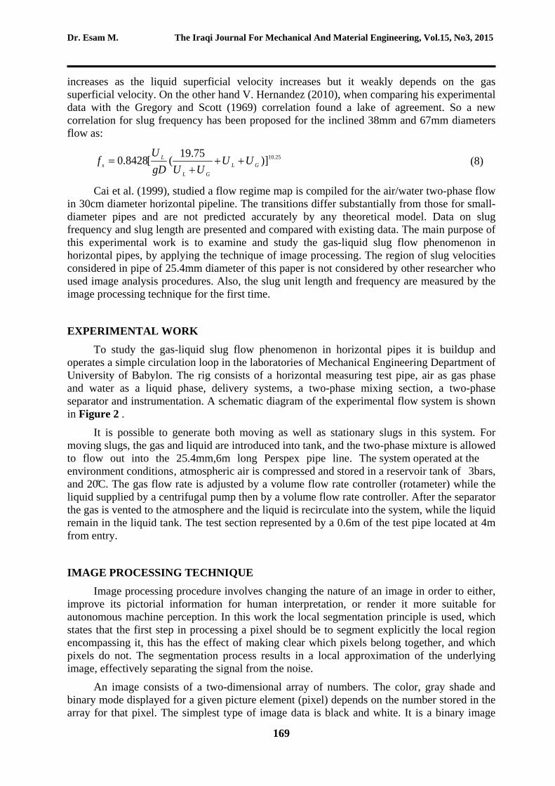
increases as the liquid superficial velocity increases but it weakly depends on the gas superficial velocity. On the other hand V. Hernandez (2010), when comparing his experimental data with the Gregory and Scott (1969) correlation found a lake of agreement. So a new correlation for slug frequency has been proposed for the inclined 38mm and 67mm diameters flow as:
25.10)]75.19([8428.0 GLGL
Ls UU
UUgDU
f +++
= (8)
Cai et al. (1999), studied a flow regime map is compiled for the air/water two-phase flow in 30cm diameter horizontal pipeline. The transitions differ substantially from those for small-diameter pipes and are not predicted accurately by any theoretical model. Data on slug frequency and slug length are presented and compared with existing data. The main purpose of this experimental work is to examine and study the gas-liquid slug flow phenomenon in horizontal pipes, by applying the technique of image processing. The region of slug velocities considered in pipe of 25.4mm diameter of this paper is not considered by other researcher who used image analysis procedures. Also, the slug unit length and frequency are measured by the image processing technique for the first time.
EXPERIMENTAL WORK
To study the gas-liquid slug flow phenomenon in horizontal pipes it is buildup and operates a simple circulation loop in the laboratories of Mechanical Engineering Department of University of Babylon. The rig consists of a horizontal measuring test pipe, air as gas phase and water as a liquid phase, delivery systems, a two-phase mixing section, a two-phase separator and instrumentation. A schematic diagram of the experimental flow system is shown in Figure 2 .
It is possible to generate both moving as well as stationary slugs in this system. For moving slugs, the gas and liquid are introduced into tank, and the two-phase mixture is allowed to flow out into the 25.4mm,6m long Perspex pipe line. The system operated at the environment conditions, atmospheric air is compressed and stored in a reservoir tank of 3bars, and 20̊C. The gas flow rate is adjusted by a volume flow rate controller (rotameter) while the liquid supplied by a centrifugal pump then by a volume flow rate controller. After the separator the gas is vented to the atmosphere and the liquid is recirculate into the system, while the liquid remain in the liquid tank. The test section represented by a 0.6m of the test pipe located at 4m from entry.
IMAGE PROCESSING TECHNIQUE Image processing procedure involves changing the nature of an image in order to either,
improve its pictorial information for human interpretation, or render it more suitable for autonomous machine perception. In this work the local segmentation principle is used, which states that the first step in processing a pixel should be to segment explicitly the local region encompassing it, this has the effect of making clear which pixels belong together, and which pixels do not. The segmentation process results in a local approximation of the underlying image, effectively separating the signal from the noise.
An image consists of a two-dimensional array of numbers. The color, gray shade and binary mode displayed for a given picture element (pixel) depends on the number stored in the array for that pixel. The simplest type of image data is black and white. It is a binary image

GAS-LIQUID SLUG FREQUENCY AND SLUG Dr. Esam M. Abed UNIT LENGTH IN HORIZONTAL PIPES Zainab K. Gheben.
170
since each pixel is either 0 or 1. The next, more complex type of image is gray scale, where each pixel takes on a value between zero and the number of gray scales or gray levels that the scanner can record. These images appear like common black and white photographs they are black, white, and shades of gray. Most gray scale images today have 256 shades of gray extend around 0 to 255; people can distinguish about 40 shades of gray. The most complex type of images is color images which are similar to gray scale except that there are three bands, or channels, corresponding to the colors red, green and blue (RGB) thus each pixel has three values associated with it; each of these components has a range of (0-255). Then each of these components has a range of 2553
x
=16777216 different possible colors in the image. Images of slug flow around the horizontal coordinate 4m from entry of the pipe were recorded using a SONY digital video camera recorder. A typical sequence snapshots recorded by the camera using a recording rate of 30 frames/s as shown in Figure 3 .The camera field of view is 720 (width) x 576 (height) pixels, the width represents the horizontal x coordinate whereas the height represents the vertical y coordinate of the image. In this work MATLAB environment is used as the image processing tool.
Each frame was converted from RGB to grey scale mode. The output image has 256 gray levels, ranging from 0 as black to 255 as white as shown in Figure 4 .
Conversion of a gray scale image to binary mode consists in a reduction to two of the number of gray levels of the original image one corresponding to black 0 and 1 corresponding to white. This is accomplished by means of a threshold value, means a pixel value or luminosity defining the transition between black and white colors. The level of accuracy of the resulting binary image or the measure of how well the binary image represents the original gray scale image is related to the luminosity chosen for threshold, in these experiments, a threshold value of 75 was used. Once the threshold value reference luminosity is defined, an image simplification takes place all pixels with luminosity values lower than the threshold value are considered black, while the remaining pixels are considered white as shown in Figure 5 . More specifically, image erosion sets the value of every pixel in an image to the minimum value of its surrounding pixels as shown in Figure 6.
The above procedure created a black and white image that can be understood as a black background with white objects in foreground. These white objects were represents the air voids which can be further processed to determine their positioning and dimension. As mentioned and y represents dimensions of the image, so, it is easy to calculate the length of the Taylor-bubble by selecting the x coordinate of the nose and tail of it, and subtracting them from each other as shown in Figure 7 ,the same manner applied on the slug body length as shown in Figure 8 .The Taylor bubble length and the slug body length can be calculated as:
tailnosef xxL −= (9)
rearfronts xxL −= (10)
The values that will get from the above equations are in pixels, to get it in m:
)(___sec_)(__sec_)()(pixelinlengthimagetionTest
minlengthtionTestpixelLmL ff ×= (11)

Dr. Esam M. The Iraqi Journal For Mechanical And Material Engineering, Vol.15, No3, 2015
171
)(___sec_)(__sec_)()(pixelinlengthimagetionTest
minlengthtionTestpixelLmL SS ×= (12)
Certainly there is an error in this procedure which resulted from the conversion steps, where the resulted binary image has some difference from the original color image and this error was found to be ±0.001m.The frequency is computed by calculating number of slug units appearing at a specific time and dividing this number on its appearing time as:
n
Nf
nt
tL
s
u∑
=
=
=1 (13)
RESULTS
In this work experiments has been accomplished for several superficial velocities ranging from 3.947 m/s to 6.579 m/s for gas phase and from 0.986m\s to 1.974m\s for liquid phase. Generally, the two-phase mixture velocity is ranged from 4.933m/s to 8.552m/s. The effects of gas superficial velocity, liquid superficial velocity on slug unit length and frequency are taken into account.
1. Slug Unit Lengths The slug unit length as mentioned earlier represent the liquid slug length plus the Taylor
bubble or the film region length, in this work by analyzing the sequence of images of the recorded videos. It is found that for all the range of experiments the slug body length was ranging around 19-23 times the pipe diameter, while the Taylor bubble length ranging around 6-20 times the pipe diameter, where the total slug unit ranging around 28-36 times the pipe diameter. In all experiments accomplished in this case, slug unit length decreases with increasing the liquid superficial velocity (the liquid volumetric flow rate dividing by the liquid entrance area) for the same gas superficial velocity. If the liquid superficial velocity increased at a constant gas superficial velocity (the gas volumetric flow rate dividing by the gas entrance area), the ratio of the liquid to the gas in the slug unit will be increased. This increase appears as film height increase and mass of gas contained by Taylor bubble decrease. Therefore, the Taylor bubble length tends to decrease, while the slug body length will be constant resulting in slug unit length decrease as shown in Figure 9 , Figure 10 and Figure 11 .On the other hand, its noted that when increasing the gas superficial velocity at constant liquid superficial velocity the slug body length tend to be constant in length while the Taylor bubble tend to be longer and its diameter increased in size which effecting the liquid film height making it to be thinner to compensate the increase in the ratio of gas to liquid entered to the system as shown in Figure 12 and Figure 13 below. So the effect of increasing the gas superficial velocity on the liquid slug and Taylor bubble lengths causing the slug unit length to be longer than another one with less superficial velocity as it appears in the Figure 14.
When comparing the present results with the previous studies found that there is a clear agreement in slug body length limits, as it shown in results that the range of the present data for 25.4mm diameter are 19D-23D, Scott et al., (1989) and Nicholson et al. (1978) and Gregory et

GAS-LIQUID SLUG FREQUENCY AND SLUG Dr. Esam M. Abed UNIT LENGTH IN HORIZONTAL PIPES Zainab K. Gheben.
172
al. (1978) correlations for slug body length are 30D as shown in Figure 15 and Figure 16 below which are for diameters of 25.4mm and 25.8mm and 25.8mm respectively.
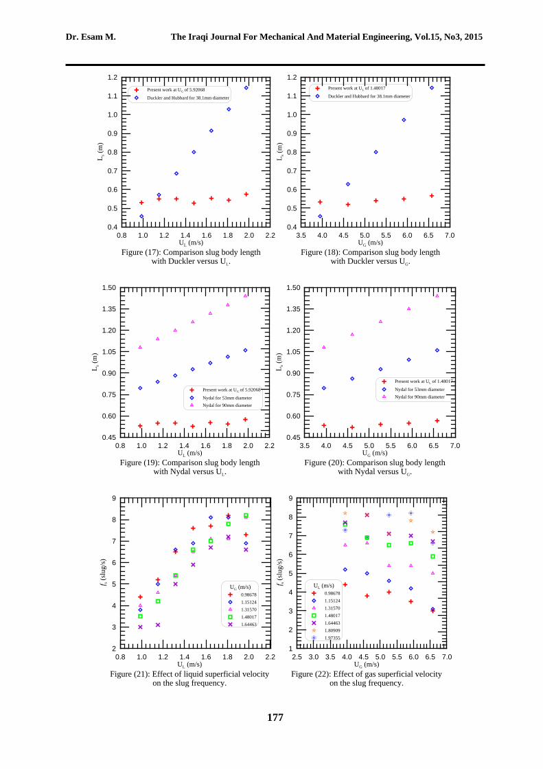
Duckler and Hubbard (1975) correlation for 38.1mm diameter is ranged around 12D-30D which are nearly in convergence with the present experimental data of this paper as shown in Figure 17 and Figure 18 . Nydal et al. (1992) correlation are ranged from 15D-20D for 53mm diameter and from 12D-16D for 90mm diameter which are in great agreement with the gotten results of 19D-23D for 25.4mm diameter, where Nydal et al. (1992) proved in his correlations that the slug body length increased with the pipe diameter decrease as shown in Figure 19 and Figure 20 . The Figures of comparison of slug body length may give indication of high differences with the present results, but there is not, where the main role of defining the slug body length is the dimensionless ratio LS/D which is in convergence for all researchers with the current results neglecting the pipe diameter size which is limiting the slug body length in each flow conditions.
2. Slug Frequency The slug period is defined as the time that a slug unit needs to pass through the
measuring device. The inverse of the slug period is the slug frequency nu at a certain position from the inlet. It is seen that slug frequency increases with increasing liquid superficial velocity for all test conditions. This increase rate is nearly 3.4slug/s if water superficial velocity increases 1m/s. Figure 21 shows the effect of liquid superficial velocity on slug frequency.
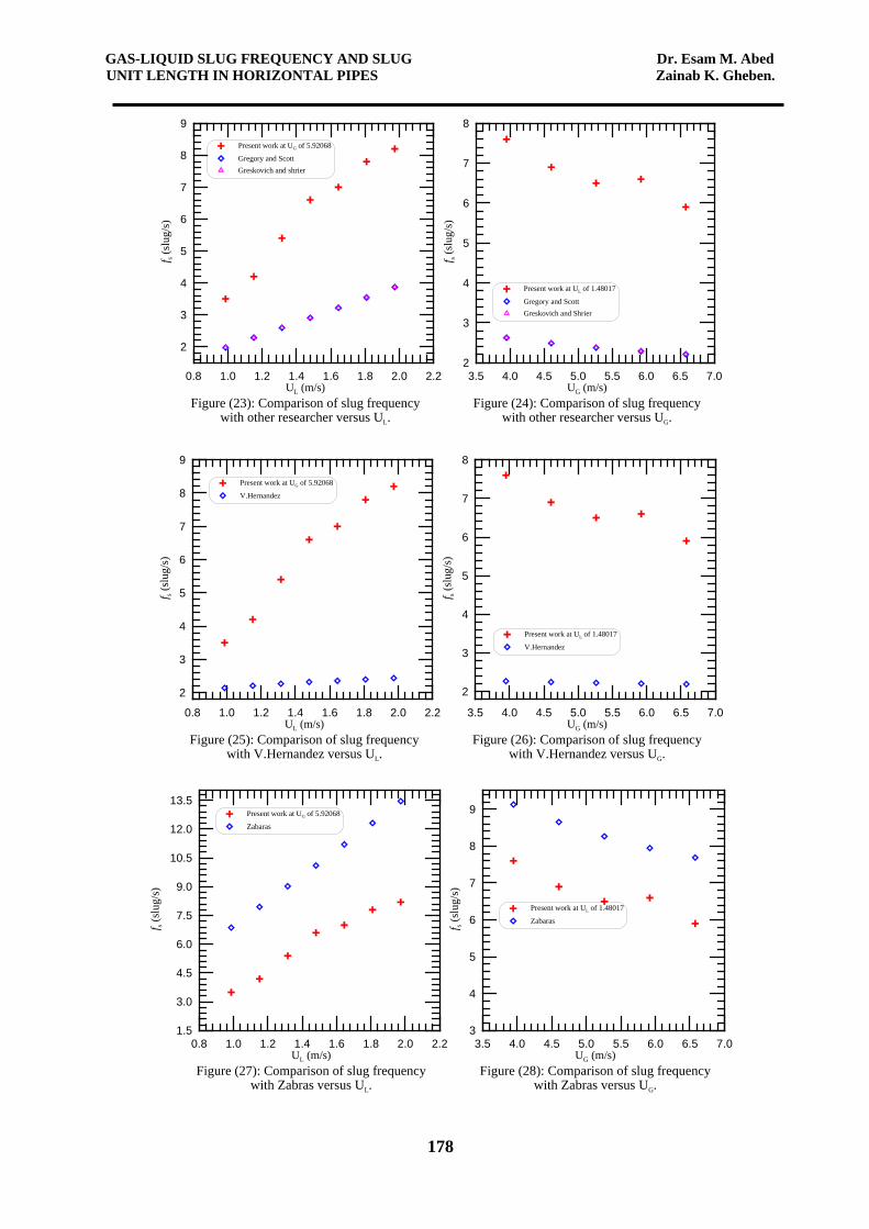
With respect to the increase in gas superficial velocity causing decrease in slug frequency as shown in Figure 22 where as a result of the constant slug body length so the increase in gas superficial velocity increasing the Taylor bubble length interpreted in lower frequent of slug unit comparing with another one have less gas superficial velocity. And this decrease limited to 0.4slug/s compensates 1m/s air superficial velocity increase. By comparing the present results with the previous works found a great agreement with them. Where in the coming Figure 23 and Figure 24 a comparison of the gotten experimental data with Gregory and Scott (1969) and Greskovich and Shrier [9] correlations are presented, it is clear that there is high similarity in behavior between the presented results and the previous correlation.
The experimental data frequency of this paper observed to be higher than the frequency gotten by the mentioned correlation this gap was due to the difference in condition that surrounding the experiments like the test pipe diameter, its length and the range of velocities tested.V. Hernandez(2010) correlation which is found to have a lake of agreement with the present data both in behavior and values as in Figure 25 and Figure 26 below. While the Figure 27 and Figure 28 below represented a comparison with Zabaras (2000) correlation where it has the same behavior, but also there is no convergence with the present data, where it is lower than the values of Zabaras (2000), the reason was as mentioned above for Gregory and Scott (1969) and Greskovich and Shrier (1972) duo to the experiment surrounding conditions.
Figure 29 and Figure 30 show the comparison of slug frequency with researches. Nydal, et al.(1992) and Shea et al.(2004) correlation like Zabaras(2000) have the same behavior with the present data but the gap between them is little high that’s due to the experiment conditions of the previous works and the presented data as it is specified earlier. Nydal and Shea correlation not representing the gas liquid flow perfectly, where they not take into account the effect of the gas superficial velocity, so it is not giving any indication about the frequency values when varying the gas superficial velocities as shown in Figure 31 and Figure 32 . It is observed that the frequency increases with decreasing the slug unit length so that the relation between the frequency and the slug unit length is inverse proportional for both constant liquid

Dr. Esam M. The Iraqi Journal For Mechanical And Material Engineering, Vol.15, No3, 2015
173
superficial velocity and constant gas superficial velocity as shown in Figure 33 and Figure 34 the relation represented by a direction arrows.
Finally it is found that the present data frequency, agreed with some of the previous works behavior but the gap between them values was relatively high due to the different condition rounded the experiment works as like as the other researchers results are differ from each other. The present frequency can give in a simple empirical correlation like of Gregory and Scott(1969)but differ in the uncertainty as:
2.1)]75.19([0478.0 GLGL
Ls UU
UUgDUf ++
+= (14)
CONCLUSION
In this paper experimental study of slug unit lengths and its frequency in horizontal circular transparent pipes of 25.4mm inner diameter and 6m length were accomplished, experiments done at atmospheric condition with air and water as working fluids. The superficial gas velocity ranged from 3.947 to 6.579 m/s with superficial liquid velocity between 0.986 and 1.974 m/s. The effects of superficial gas velocity, superficial liquid velocity on slug unit lengths and slug frequency were taken into account. From this work it is observed that
1. The slug body lengths ranging around 19D-23D, and Taylor bubble around 6D-20D where the total slug unit extend on 28D-36D. And these ranges for slug body length are agreed in highly with the previous works.
2. Also, it is found that the slug unit length decrease with increasing the liquid superficial velocity for the same gas superficial velocity, while it is increase with increasing the gas superficial velocity for the same liquid superficial velocity.
3. For frequency field it is observed that when increasing the liquid superficial velocity the slug frequency increased, whereas increasing the gas superficial velocity causing decrease in slug frequency.
4. Then it is found that both the gas phase and liquid phase superficial velocities are an important factor in computing the slug frequency.
5. Slug unit length is reverse proportional to the slug frequency versus both gas and liquid superficial velocities.
6. The present frequency can give in a simple empirical correlation like of Gregory and Scott (1969) but differ in the uncertainty as Equ. (14).
7. An agreement of the frequency of present work with the previous works in behavior was found, but there is relatively high gap between the frequency values from previous works to ascribe to the difference in condition that surrounding the experiments like the test pipe diameter, its length and the range of velocities tested.

GAS-LIQUID SLUG FREQUENCY AND SLUG Dr. Esam M. Abed UNIT LENGTH IN HORIZONTAL PIPES Zainab K. Gheben.
174
Figure 1. slug unit due to Dukler and Hubbard model(1975).
Figure 2 . Experiment set up.
Figure 3 . color images.

Dr. Esam M. The Iraqi Journal For Mechanical And Material Engineering, Vol.15, No3, 2015
175
Figure 4 . conversion to gray scale image.
Figure 5 . binary image. Figure 6 . eroded binary image.
Figure 7 . taylor-bubble length measuring.
Figure 8 . slug body length measuring.
0.80 1.00 1.20 1.40 1.60 1.80 2.00 2.20UL (m/s)
Figure (9): Effect of liquid superficial velocityon the slug body length.
0.46
0.48
0.50
0.52
0.54
0.56
0.58
0.60
L s (m
)
UG (m/s)3.947124.604965.262805.920686.57852
0.8 1.0 1.2 1.4 1.6 1.8 2.0 2.2UL (m/s)
Figure (10): Effect of liquid superficial velocityon the Taylor bubble length.
0.10
0.15
0.20
0.25
0.30
0.35
0.40
0.45
0.50
0.55
L f (m
)
UG (m/s)3.947124.604965.262805.920686.57852

GAS-LIQUID SLUG FREQUENCY AND SLUG Dr. Esam M. Abed UNIT LENGTH IN HORIZONTAL PIPES Zainab K. Gheben.
176
0.8 1.0 1.2 1.4 1.6 1.8 2.0 2.2UL (m/s)
Figure (11): Effect of liquid superficial velocityon the slug unit length.
0.70
0.75
0.80
0.85
0.90
0.95
1.00
1.05
1.10
1.15L u
(m)
UG (m/s)3.947124.604965.262805.920686.57852
3.5 4.0 4.5 5.0 5.5 6.0 6.5 7.0UG (m/s)
Figure (12): Effect of gas superficial velocityon the slug body length.
0.46
0.48
0.50
0.52
0.54
0.56
0.58
0.60
L s (m
)
UL (m/s)0.986781.151241.315701.480171.644631.809091.97355
3.5 4.0 4.5 5.0 5.5 6.0 6.5 7.0UG (m/s)
Figure (13): Effect of gas superficial velocityon the Taylor bubble length.
0.10
0.20
0.30
0.40
0.50
0.60
L f (m
)
UL (m/s)0.986781.151241.315701.480171.644631.809091.97355
2.5 3.0 3.5 4.0 4.5 5.0 5.5 6.0 6.5 7.0UG (m)
Figure (14): Effect of gas superficial velocityon the slug unit length.
0.72
0.80
0.88
0.96
1.04
1.12
1.20
L u (m
)
UL (m/s)0.986781.151241.315701.480171.644631.809091.97355
0.8 1.0 1.2 1.4 1.6 1.8 2.0 2.2UL (m/s)
Figure (15): Comparison of slug body lengthwith other researcher versus UL.
0.50
0.55
0.60
0.65
0.70
0.75
0.80
L s (m
)
Present work at UG of 5.92068
Gregory for 25.8mm diameterNicholson for 25.8mm diameterScott for 25.4mm diameter
3.5 4.0 4.5 5.0 5.5 6.0 6.5 7.0UG (m/s)
Figure (16): Comparison of slug body lengthwith other researcher versus UG.
0.50
0.55
0.60
0.65
0.70
0.75
0.80
L s (m
)
Present work at UL of 1.48017
Gregory for 25.8mm diameterNicholson for 25.8mm diameterScott for 25.4mm diameter
Dr. Esam M. The Iraqi Journal For Mechanical And Material Engineering, Vol.15, No3, 2015
177
0.8 1.0 1.2 1.4 1.6 1.8 2.0 2.2UL (m/s)
Figure (17): Comparison slug body lengthwith Duckler versus UL.
0.4
0.5
0.6
0.7
0.8
0.9
1.0
1.1
1.2
L s (m
)Present work at UG of 5.92068
Duckler and Hubbard for 38.1mm diameter
3.5 4.0 4.5 5.0 5.5 6.0 6.5 7.0UG (m/s)
Figure (18): Comparison slug body lengthwith Duckler versus UG.
0.4
0.5
0.6
0.7
0.8
0.9
1.0
1.1
1.2
L s (m
)
Present work at UL of 1.48017
Duckler and Hubbard for 38.1mm diameter
0.8 1.0 1.2 1.4 1.6 1.8 2.0 2.2UL (m/s)
Figure (19): Comparison slug body lengthwith Nydal versus UL.
0.45
0.60
0.75
0.90
1.05
1.20
1.35
1.50
L s (m
)
Present work at UG of 5.92068
Nydal for 53mm diameterNydal for 90mm diameter
3.5 4.0 4.5 5.0 5.5 6.0 6.5 7.0UG (m/s)
Figure (20): Comparison slug body lengthwith Nydal versus UG.
0.45
0.60
0.75
0.90
1.05
1.20
1.35
1.50L s (
m)
Present work at UL of 1.48017
Nydal for 53mm diameterNydal for 90mm diameter
0.8 1.0 1.2 1.4 1.6 1.8 2.0 2.2UL (m/s)
Figure (21): Effect of liquid superficial velocityon the slug frequency.
2
3
4
5
6
7
8
9
f s (sl
ug/s
)
UG (m/s)0.986781.151241.315701.480171.64463
2.5 3.0 3.5 4.0 4.5 5.0 5.5 6.0 6.5 7.0UG (m/s)
Figure (22): Effect of gas superficial velocityon the slug frequency.
1
2
3
4
5
6
7
8
9
f s (sl
ug/s
)
UL (m/s)0.986781.151241.315701.480171.644631.809091.97355
GAS-LIQUID SLUG FREQUENCY AND SLUG Dr. Esam M. Abed UNIT LENGTH IN HORIZONTAL PIPES Zainab K. Gheben.
178
0.8 1.0 1.2 1.4 1.6 1.8 2.0 2.2UL (m/s)
Figure (23): Comparison of slug frequencywith other researcher versus UL.
2
3
4
5
6
7
8
9
f s (sl
ug/s
)
Present work at UG of 5.92068
Gregory and Scott Greskovich and shrier
3.5 4.0 4.5 5.0 5.5 6.0 6.5 7.0UG (m/s)
Figure (24): Comparison of slug frequencywith other researcher versus UG.
2
3
4
5
6
7
8
f s (sl
ug/s
)
Present work at UL of 1.48017
Gregory and ScottGreskovich and Shrier
0.8 1.0 1.2 1.4 1.6 1.8 2.0 2.2UL (m/s)
Figure (25): Comparison of slug frequencywith V.Hernandez versus UL.
2
3
4
5
6
7
8
9
f s (sl
ug/s
)
Present work at UG of 5.92068
V.Hernandez
3.5 4.0 4.5 5.0 5.5 6.0 6.5 7.0UG (m/s)
Figure (26): Comparison of slug frequencywith V.Hernandez versus UG.
2
3
4
5
6
7
8f s (
slug
/s)
Present work at UL of 1.48017
V.Hernandez
0.8 1.0 1.2 1.4 1.6 1.8 2.0 2.2UL (m/s)
Figure (27): Comparison of slug frequencywith Zabras versus UL.
1.5
3.0
4.5
6.0
7.5
9.0
10.5
12.0
13.5
f s (sl
ug/s
)
Present work at UG of 5.92068
Zabaras
3.5 4.0 4.5 5.0 5.5 6.0 6.5 7.0UG (m/s)
Figure (28): Comparison of slug frequencywith Zabras versus UG.
3
4
5
6
7
8
9
f s (sl
ug/s
)
Present work at UL of 1.48017
Zabaras

Dr. Esam M. The Iraqi Journal For Mechanical And Material Engineering, Vol.15, No3, 2015
179
0.8 1.0 1.2 1.4 1.6 1.8 2.0 2.2UL (m/s)
Figure (29): Comparison of slug frequencywith Nydal versus UL.
2
3
4
5
6
7
8
9
f s (sl
ug/s
)Present work at UG of 5.92068
Nydal
0.8 1.0 1.2 1.4 1.6 1.8 2.0 2.2UL (m/s)
Figure (30): Comparison of slug frequencywith Shea versus UL.
0
5
10
15
20
25
30
f s (sl
ug/s
)
Present work at UG of 5.92068
Shea
3.5 4.0 4.5 5.0 5.5 6.0 6.5 7.0UG (m/s)
Figure (31): Comparison of slug frequencywith Nydal versus UG.
2
3
4
5
6
7
8
f s (sl
ug/s
)
Present work at UL of 1.48017
Nydal
3.5 4.0 4.5 5.0 5.5 6.0 6.5 7.0UG (m/s)
Figure (32): Comparison of slug frequencywith Shea versus UG.
3
6
9
12
15
18
21
f s (sl
ug/s
)
Present work at UL of 1.48017
Shea
0.8 1.0 1.2 1.4 1.6 1.8 2.0UL (m/s)
Figure (33): Relation between slug unitlength and frequency versus UL.
0.80
0.85
0.90
0.95
1.00
1.05
1.10
L u (m
)
3
4
5
6
7
8
9
f s (s
lug/
s)
Slug unit lengthSlug frequency
3.5 4.0 4.5 5.0 5.5 6.0 6.5 7.0UG (m/s)
Figure (34): Relation between slug unitlength and frequency versus UG.
0.75
0.78
0.81
0.84
0.87
0.90
0.93
0.96
L u (m
)
6.0
6.3
6.6
6.9
7.2
7.5
7.8
f s (sl
ug/s
)Slug unit lengthSlug frequency

GAS-LIQUID SLUG FREQUENCY AND SLUG Dr. Esam M. Abed UNIT LENGTH IN HORIZONTAL PIPES Zainab K. Gheben.
180
REFERENCES
Al-Safran, E.,2009, "Investigation and Prediction of Slug Frequency in Gas/Liquid Horizontal Pipe Flow".published in J. if Petroleum Sci. and Eng.
Cai, J.Y., Wang, R.W.,Hong, T. and Jepson, W.P., 1999, "slug frequency and Length inclined Large Diameter Multiphase Pipeline".Multiphase Flow and Heat Transfer, Proc. of the Fourth International Symposium', China.
Cook, M., Behnia, M.,2000, "Slug Length Prediction in Near Horizontal Gas-Liquid Intermittent Flow".Chemical Engineering Science, 55,(2009-2018).
Dukler, A. E. and Hubbard, M. G. ,1975, "A Model for Gas-Liquid Slug Flow in Horizontal and Near Horizontal Tubes".Journal of Ind. Eng. Chem. Fundamentals, Vol. 14, pp. 337-347.
Gregory G. A. Nicholson, M. K., Aziz, K.,1978, "Correlation of the liquid volume fraction in the slug for horizontal gas-liquid slug flow". In: International Journal of Multiphase Flow (1978), No. 1, pp. 33–39.
Gregory, G. A. and Scott, D. S.,1969, "Correlation of liquid slug velocity and frequency in horizontal co-current gas-liquid slug flow", AIChEJournal , Vol. 15, pp. 833-835.
Greskovich, E. J. and Shrier, A. L.,1972, "Slug frequency in horizontal gas-liquid slug flow". Ind. Eng. Chem. Proc. Design Dev., Vol. 11, No. 2, pp. 317-318.
Hernandez-Perez, V., Abdulkadir, M., Azzopardi, J., 2010, "Slugging frequency correlation for inclined gas–liquid flow".World Acad. Sci., Eng. Technol. 6, 44–51.
Magalhaes, G.R., Gonçalves, G.F.N., Loureiro, J.B.R., Silva, F.A.P., 2013, "An experimental investigation of the effects of gas solubility on the propertiesof horizontal slug flow". International Journal of Multiphase Flow, 50, 33–40.
Nicholson M. K. Aziz, K. Gregory, G. A.,1978, "Intermittent two phase flow in horizontal pipes: predictive models". In: The Canadian Journal of Chemical Engineering 56 (1978), pp. 653–663.
Nydal O. J.Pintus, S.; Andreussi, P., 1992, "Statistical characterization of slug flow in horizontal pipes".International Journal of Multiphase Flow 18, No. 3, pp. 439–452.
Scott, S. L., Shoham, O., Brill, J. P., 1989, "Prediction of Slug Length in Horizontal Large-Diameter Pipes".SPEPE Aug., 335.
Shea, R., Eidsmoen, H., Nordsveen, M., Rasmussen, J. Xu, Z., Nossen, J.,2004, "Frequency Prediction Method Comparison.BHRG Multi-phase Production Technology Proceedings".Bannf, Canada.
Wang, X., Guo, L., Zhang, X.,2007, "An experimental study of the statistical parameters of gas–liquid two-phase slug flow in horizontal pipeline".Int. J. Heat Mass Transfer 50, 2439–2443.
Zabaras, G. J., 2000, "Prediction of Slug Frequency for Gas-Liquid Flows". SPEJ, Sept, 252.