Gas Lift Valve Testing - ALRDC · Gas Lift Valve Testing Angel Wileman, Research Engineer Southwest...
33
Feb. 4 – 8, 2013 2013 Gas-Lift Workshop 1 Gas Lift Valve Testing Angel Wileman, Research Engineer Southwest Research Institute, Fluid Dynamics 36 th Gas-Lift Workshop Stavanger, Norway February 4 – 8, 2013
Transcript of Gas Lift Valve Testing - ALRDC · Gas Lift Valve Testing Angel Wileman, Research Engineer Southwest...

Feb. 4 – 8, 2013 2013 Gas-Lift Workshop 1
Gas Lift Valve Testing
Angel Wileman, Research Engineer
Southwest Research Institute, Fluid Dynamics
36th Gas-Lift Workshop Stavanger, Norway February 4 – 8, 2013

Feb. 4 – 8, 2013 2013 Gas-Lift Workshop 2
Gas Lift Valve Test Methods
Presentation Contents
• Overview of 19G2 Standard and Tests
• Background on SwRI
• Testing Methods and Facilities
• Other Testing
• Conclusion

API 19G2 Flow-Control Devices for Side-Pocket Mandrels
• Released June 2010, effective December 2010
• Validation Testing (Level V1, V2, V3)
– Performed once per design
• Function Testing (Level F1, F2, and F3)
– Performed on every valve sold
• SwRI has performed Validation Tests and custom tests
to meet customer specifications
– 19G2 does not require 3rd party test facility to perform tests
– Test setups intended for flexibility in testing and customer
requirements
Feb. 4 – 8. 2013 2013 Gas-Lift Workshop
3

API 19G2 Validation Testing
Validation testing
– Annex E: Interface testing
– Annex F: Insertion testing
– Annex G: Probe and travel testing and load rate determination
– Annex H: Dynamic flow testing and flow coefficient, Cv, calculation
– Annex I: Back-check testing
– Annex J: Open and closing pressure testing
– Annex K: Bellows actuation life cycle testing
– Annex L: Erosion testing
– Annex M: Shelf testing
– Annex N: Port/seat leakage rate testing
Feb. 4 – 8. 2013 2013 Gas-Lift Workshop
4

API 19G2 Validation Testing at SwRI
Feb. 4 – 8. 2013 2013 Gas-Lift Workshop
5
Validation testing performed at SwRI
– Annex E: Interface testing
– Annex F: Insertion testing
– Annex G: Probe and travel testing and load rate
determination
– Annex H: Dynamic flow testing and flow coefficient, Cv,
calculation
– Annex I: Back-check testing
– Annex J: Open and closing pressure testing
– Annex K: Bellows actuation life cycle testing
– Annex L: Erosion testing
– Annex M: Shelf testing
– Annex N: Port/seat leakage rate testing
Southwest Research Institute
Feb. 4 – 8. 2013 2013 Gas-Lift Workshop
6
• Founded in 1947
• Private, independent , applied
R&D company
• Over 3,000 employees
• 11 technical divisions
• Revenue in 2012 exceeded
$557 million (over 4,200
contracts)
• Over 1,200 acres / 4.86 km2
facility in San Antonio, Texas
Fluid Dynamics
Test Facilities
Mission Statement: Benefiting government, industry and
the public through innovative science and technology.

19G2 Testing Requirements
• Pressure and Flow Requirements
– Water and gas static pressure testing (low and high
pressure)
– Low pressure water flow testing
– High pressure gas flow testing
• Data Acquisition and Software Requirements
– Measurement of pressure, temperature, and flow rate
– Gas flow control through control valves
– Perform all tests safely
Feb. 4 – 8. 2013
2013 Gas-Lift Workshop
7

Fluid Dynamics Section
Feb. 4 – 8. 2013 2013 Gas-Lift Workshop
8
Gas Test Facility
High Bay
High-Pressure Test
Cell
Annex G / Annex L
Annex H Annex I

Annex G: Load and Travel Testing and Load Rate Determination
• Probe Travel Test
– Determines the maximum effective travel distance for
each device
– Performed on a minimum of 7 flow control devices of
each type
– Stem travel measured with a micrometer or linearly
variable differential transformer (LVDT)
– Probe travel measured a minimum of 5 points along the
travel (including maximum travel)
• Load Rate Determination
– Calculated value from the results of the probe travel test
Feb. 4 – 8. 2013
2013 Gas-Lift Workshop
9

Annex G: Load and Travel Testing and Load Rate Determination
• Custom-built load rate testing fixture
for PPO valves
• Fixture rated to 3,000 psi
• LVDT used to measure valve stem
displacement
Feb. 4 – 8. 2013 2013 Gas-Lift Workshop
10
Pressure
measurement
Gas Lift
Valve
LVDT
(obscured)
PT
N2 Pressure
Source

Load Rate Determination
Feb. 4 – 8. 2013 2013 Gas-Lift Workshop
11
Slope of this section
is the load rate
Section of pressure rise
without stem movement

Annex H – Flow Coefficient and Dynamic Flow Testing
• Flow coefficient measurement, Cv
– Measured for each valve and port size
– Measured at five points along stem travel (10%, 30%, 50%,
70%, and 100% open)
– Performed with a modified valve
• Dynamic flow testing
– Performed with a complete, unmodified valve
– Performed for min. and max. port size, and every 1/8-inch in
between (normally 4 or more valves per test)
– Test performed at 6 constant injection or production
pressures per valve
Feb. 4 – 8. 2013 2013 Gas-Lift Workshop
12

Nitrogen Gas Test Facilities
Flow Rate
Measurement
Horizontal
Test Section
Area
High-Pressure
Nitrogen Gas Storage
LN2 Storage
Discharge to
Atmosphere
Vertical Test
Section
Cryogenic Pump Heat Exchanger

Gas Flow Testing

Gas Flow Testing
• Constant injection pressure
• Controlled remotely by a custom
Labview program
• Exhausts to atmosphere
• Programmable pressure ramps
(based on system capabilities and
valve time constant)
• Flow rate measured by a 3” orifice
flow meter (AGA3 & NIST)
Feb. 4 – 8. 2013 2013 Gas-Lift Workshop
15
Upstream
Control Valve
Flow
Test Section
Upstream
Temperature
and Pressure
Measurement
Downstream
Temperature
and Pressure
Measurement

Nitrogen Gas Test Facility Capabilities
• Maximum flow rate: 10 mmscfd (196 m3/min)
• Maximum upstream flow pressure: ~2,700 psi (187 bar)
• Maximum differential pressure: ~2,700 psi
• Nitrogen storage capacity: 1,125 ft3 (32 m3) at 3,000
psi (207 bar)
• Blowdown system flow time is a function of flow
rate and pressure
– 10 mmscfd at 1,500 psi upstream = ~6 min. steady flow
– 1 mmscfd at 2,000 psi upstream = ~20 min. steady flow
Feb. 4 – 8. 2013 2013 Gas-Lift Workshop
16

Valve Modification – Cv Testing
• Flow coefficient testing
valve modifications
– Create adjustable stem to
control stem travel
– Internal flow passage must not
be modified
Feb. 4 – 8. 2013 2013 Gas-Lift Workshop
17
Unmodified
Valve
Modified Valve
Adjustable
Stem
Unmodified
Flow
Passage

Dynamic Testing Example
Feb. 4 – 8. 2013 2013 Gas-Lift Workshop
18
Choked Flow

Flow Coefficient Data Evaluation
Feb. 4 – 8. 2013 2013 Gas-Lift Workshop
19
Cv
Data also used to calculate
Critical Pressure Ratio (Rp,crt)

Flow Coefficient Data Evaluation
Feb. 4 – 8. 2013 2013 Gas-Lift Workshop
20

Annex I: Back-Check Testing
• Mechanical function test
– Apply pressure with water to ensure the check dart moves freely
without human intervention
• Backflow integrity test
– Apply water pressure (to valve’s maximum rated pressure) on the
downstream side of the check and measure through leakage
through pressure decay
• Gas Test
– Apply 100 psi of nitrogen gas to downstream of check and
measure through leakage with a gas flow meter
• Activation test
– Measure pressure required to open normally closed spring
loaded valves ( or flow required to close a reverse-flow valve)
Feb. 4 – 8. 2013 2013 Gas-Lift Workshop
21

Annex I: Back-Check Testing
Performed in the high-pressure test cell
(2 cells available at FCTF, 3rd cell coming
late 2013)
• Capable of withstanding catastrophic
failure of the test article
• Max. N2 gas pressure: 40,000 psi
• Max. water pressure: 40,000 psi
• Max. hydraulic oil pressure: 35,000 psi
• Test fixtures locally heated or cooled
• Pressure applied remotely from a
control room for safety
Feb. 4 – 8. 2013 2013 Gas-Lift Workshop
22

Annex I: Back-Check Testing
• Water or gas can
be supplied to gas
lift valves (water
configuration
shown)
• Vents double as
flow meter ports
during gas tests
• Test fixtures can
be isolated
Feb. 4 – 8. 2013 2013 Gas-Lift Workshop
23
Upstream
Downstream

Annex I: Back-Check Testing
Feb. 4 – 8. 2013 2013 Gas-Lift Workshop
24
Test Fixture
Upstream
Connection
Water Pump
Volume Bottles
Vent
Valve Upstream Pressure
Transmitters
Downstream
Connection
Photo courtesy of Schlumberger
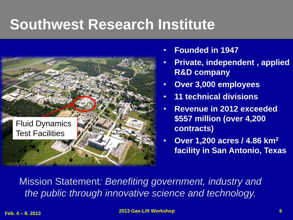
Erosion Testing – Annex L
• Performed to simulate initial unloading of a well
– Fresh water flow through complete valve
– Flow rate fixed at 1 bbl/min (0.16m3/min) for a total flow
of 400 bbl (63.6 m3)
SwRI Gas Lift Valve
Flow Fixture
Upstream Pressure
Transducer
Differential
Pressure
Transducer
Upstream
Temperature
Transducer
Flow
Direction
From tank, pump,
flowmeter
Feb. 4 – 8. 2013 2013 Gas-Lift Workshop
25

Other Gas Lift Valve Testing (other than 19G2)
• Sand slurry erosion testing
– Sand types: fine to very course
• Flow provided by triplex
pump
– Pressure: 3,600 psi (257 bar)
– Flow rate: 0.7 BBL/min (28 gpm)
Feb. 4 – 8. 2013 2013 Gas-Lift Workshop
26

Other Gas Lift Valve Testing (other than 19G2)
• Packing qualification
– Seal integrity of gas lift valve
packings
– Pressure differential holds with
water and gas
– Temperatures: Cryogenic (LN2) to
400ºF
– Gas through leakage measured
with flow meter or bubble cup
– Water through leakage measured
through pressure decay
Feb. 4 – 8. 2013 2013 Gas-Lift Workshop
27
Photo courtesy of Schlumberger
Test Fixtures
Cooling Coils
Pressure Application or
Leakage lines

API 19G1 – Mandrel Qualification
Side Pocket Mandrel
Qualification
• Inclinable test section
– 100 ft long
– Inclination up to 90º
• Horizontal and inclined
running and pulling tests
• Pressure strain gauge tests
Feb. 4 – 8. 2013 2013 Gas-Lift Workshop
28
Inclinable
Test
Section
Jar
Actuation
Rope
Hand
Crank
Winches
Pulleys
Wire Rope
Photo courtesy of Schlumberger

Revisions to 19G2
• Task groups meeting to revise 19G2
– Add a V0 validation level (currently V1, V2, and V3)
• modeled after the Statoil qualification test
– Remove gas flow testing from Functional Testing
Feb. 4 – 8. 2013 2013 Gas-Lift Workshop
29

Summary
• All valves stamped with the API 19G2 monogram
undergo some or all of the testing mentioned in this
presentation.
• There are several ways to do the tests outlined in
19G2, but certain high pressure water and gas
facilities are required.
Feb. 4 – 8. 2013 2013 Gas-Lift Workshop
30

Questions?
Feb. 4 – 8. 2013 2013 Gas-Lift Workshop
31

Feb. 4 – 8, 2013 2013 Gas-Lift Workshop 32
Copyright
Rights to this presentation are owned by the company(ies) and/or author(s) listed on the title page. By submitting this presentation to the Gas-Lift Workshop, they grant to the Workshop, the Artificial Lift Research and Development Council (ALRDC), and the American Society of Mechanical Engineers (ASME), rights to:
– Display the presentation at the Workshop.
– Place it on the www.alrdc.com web site, with access to the site to be as directed by the Workshop Steering Committee.
– Place it on a CD for distribution and/or sale as directed by the Workshop Steering Committee.
Other uses of this presentation are prohibited without the expressed written permission of the company(ies) and/or author(s) who own it and the Workshop Steering Committee.

Feb. 4 – 8, 2013 2013 Gas-Lift Workshop 33
Disclaimer
The following disclaimer shall be included as the last page of a Technical Presentation or Continuing Education Course. A similar disclaimer is included on the front page of the Gas-Lift Workshop Web Site.
The Artificial Lift Research and Development Council and its officers and trustees, and the Gas-Lift Workshop Steering Committee members, and their supporting organizations and companies (here-in-after referred to as the Sponsoring Organizations), and the author(s) of this Technical Presentation or Continuing Education Training Course and their company(ies), provide this presentation and/or training material at the Gas-Lift Workshop "as is" without any warranty of any kind, express or implied, as to the accuracy of the information or the products or services referred to by any presenter (in so far as such warranties may be excluded under any relevant law) and these members and their companies will not be liable for unlawful actions and any losses or damage that may result from use of any presentation as a consequence of any inaccuracies in, or any omission from, the information which therein may be contained.
The views, opinions, and conclusions expressed in these presentations and/or training materials are those of the author and not necessarily those of the Sponsoring Organizations. The author is solely responsible for the content of the materials.
The Sponsoring Organizations cannot and do not warrant the accuracy of these documents beyond the source documents, although we do make every attempt to work from authoritative sources. The Sponsoring Organizations provide these presentations and/or training materials as a service. The Sponsoring Organizations make no representations or warranties, express or implied, with respect to the presentations and/or training materials, or any part thereof, including any warrantees of title, non-infringement of copyright or patent rights of others, merchantability, or fitness or suitability for any purpose.