GAS INSERT - Manufacturer of Fireplaces, Grills, Furnaces · NAPOLEON gas fireplaces are...
15
WS-415-44 /11.06.98 GAS INSERT GAS INSERT GAS INSERT GAS INSERT GAS INSERT INST INST INST INST INSTALLA ALLA ALLA ALLA ALLATION AND OPERA TION AND OPERA TION AND OPERA TION AND OPERA TION AND OPERATION INSTRUCTIONS FOR TION INSTRUCTIONS FOR TION INSTRUCTIONS FOR TION INSTRUCTIONS FOR TION INSTRUCTIONS FOR GAS-FIRED GAS-FIRED GAS-FIRED GAS-FIRED GAS-FIRED VENTED ROOM HEA VENTED ROOM HEA VENTED ROOM HEA VENTED ROOM HEA VENTED ROOM HEATER TER TER TER TER NATURAL GAS MODEL GI3014-N / GI3014B-N GI3014-N / GI3014B-N GI3014-N / GI3014B-N GI3014-N / GI3014B-N GI3014-N / GI3014B-N PROPANE GAS MODEL GI3014-P / GI3014B-P GI3014-P / GI3014B-P GI3014-P / GI3014B-P GI3014-P / GI3014B-P GI3014-P / GI3014B-P GAS-ZERO CLEARANCE WHEN INSTALLED WITH GI-700 KIT WITHOUT GI-700 KIT INSTALL RECESSED INTO A WOODBURNING NON-COMBUSTIBLE FIREPLACE CERTIFICATION LABEL AFFIXED TO UNDERSIDE OF FRESH AIR DAMPER INST INST INST INST INSTALLER: THESE INSTRUCTIONS MUST BE CONVEYED TO AND REMAIN WITH THE HOMEOWNER. ALLER: THESE INSTRUCTIONS MUST BE CONVEYED TO AND REMAIN WITH THE HOMEOWNER. ALLER: THESE INSTRUCTIONS MUST BE CONVEYED TO AND REMAIN WITH THE HOMEOWNER. ALLER: THESE INSTRUCTIONS MUST BE CONVEYED TO AND REMAIN WITH THE HOMEOWNER. ALLER: THESE INSTRUCTIONS MUST BE CONVEYED TO AND REMAIN WITH THE HOMEOWNER. CERTIFIED UNDER CANADIAN AND AMERICAN NATIONAL STANDARDS, CSA 2.33 AND ANSI Z21.88 RESPECTIVELY FOR VENTED GAS FIREPLACE HEATERS Fax: (705)722-6031 EMAIL: [email protected] WEB: www.napoleon.on.ca Wolf Steel Ltd., RR#1, 9 Napoleon Rd., Barrie, On., Canada L4M 4Y8 (705)721-1212 R-2000 W ARNING: ARNING: ARNING: ARNING: ARNING: If the information in these instructions is not followed exactly, a fire or explosion may result causing property damage, personal injury or death. FOR YOUR SAFETY FOR YOUR SAFETY FOR YOUR SAFETY FOR YOUR SAFETY FOR YOUR SAFETY Do not store or use gasoline or other flammable vapours and liquids in the vicinity of this or any other appliance. WHA WHA WHA WHA WHA T T T T T T O DO IF YOU SMELL O DO IF YOU SMELL O DO IF YOU SMELL O DO IF YOU SMELL O DO IF YOU SMELL GAS: GAS: GAS: GAS: GAS: • Do not try to light any appliance. • Do not touch any electrical switch. • Do not use any phone in your building. • Immediately call your gas supplier from a neighbor's phone. Follow the gas suppli- er's instructions. • If you cannot reach your gas supplier, call the fire department. Installation and service must be performed by a qualified installer, service agency or the gas supplier.
Transcript of GAS INSERT - Manufacturer of Fireplaces, Grills, Furnaces · NAPOLEON gas fireplaces are...

WS-415-44 /11.06.98
GAS INSERTGAS INSERTGAS INSERTGAS INSERTGAS INSERTINSTINSTINSTINSTINSTALLAALLAALLAALLAALLATION AND OPERATION AND OPERATION AND OPERATION AND OPERATION AND OPERATION INSTRUCTIONS FORTION INSTRUCTIONS FORTION INSTRUCTIONS FORTION INSTRUCTIONS FORTION INSTRUCTIONS FOR
GAS-FIRED GAS-FIRED GAS-FIRED GAS-FIRED GAS-FIRED VENTED ROOM HEA VENTED ROOM HEA VENTED ROOM HEA VENTED ROOM HEA VENTED ROOM HEATERTERTERTERTER
NATURAL GAS MODEL GI3014-N / GI3014B-NGI3014-N / GI3014B-NGI3014-N / GI3014B-NGI3014-N / GI3014B-NGI3014-N / GI3014B-NPROPANE GAS MODEL GI3014-P / GI3014B-PGI3014-P / GI3014B-PGI3014-P / GI3014B-PGI3014-P / GI3014B-PGI3014-P / GI3014B-P
GAS-ZERO CLEARANCE WHEN INSTALLED WITH GI-700 KITWITHOUT GI-700 KIT INSTALL RECESSED INTO A WOODBURNING NON-COMBUSTIBLE FIREPLACE
CERTIFICATION LABEL AFFIXED TO UNDERSIDE OF FRESH AIR DAMPER
INSTINSTINSTINSTINSTALLER: THESE INSTRUCTIONS MUST BE CONVEYED TO AND REMAIN WITH THE HOMEOWNER.ALLER: THESE INSTRUCTIONS MUST BE CONVEYED TO AND REMAIN WITH THE HOMEOWNER.ALLER: THESE INSTRUCTIONS MUST BE CONVEYED TO AND REMAIN WITH THE HOMEOWNER.ALLER: THESE INSTRUCTIONS MUST BE CONVEYED TO AND REMAIN WITH THE HOMEOWNER.ALLER: THESE INSTRUCTIONS MUST BE CONVEYED TO AND REMAIN WITH THE HOMEOWNER.CERTIFIED UNDER CANADIAN AND AMERICAN NATIONAL STANDARDS, CSA 2.33 AND ANSI Z21.88 RESPECTIVELY FOR VENTED GAS FIREPLACE HEATERS
Fax: (705)722-6031 EMAIL: [email protected]
WEB: www.napoleon.on.ca
Wolf Steel Ltd., RR#1, 9 Napoleon Rd.,Barrie, On., Canada L4M 4Y8 (705)721-1212
R-2000
WWWWWARNING:ARNING:ARNING:ARNING:ARNING: If the information in these instructions is not followed exactly, a fire orexplosion may result causing property damage, personal injury or death.
FOR YOUR SAFETYFOR YOUR SAFETYFOR YOUR SAFETYFOR YOUR SAFETYFOR YOUR SAFETYDo not store or use gasoline or other flammable vapours and liquids in the vicinity of
this or any other appliance.
WHAWHAWHAWHAWHATTTTT T T T T TO DO IF YOU SMELLO DO IF YOU SMELLO DO IF YOU SMELLO DO IF YOU SMELLO DO IF YOU SMELL GAS: GAS: GAS: GAS: GAS:• Do not try to light any appliance.• Do not touch any electrical switch.• Do not use any phone in your building.
• Immediately call your gas supplier from aneighbor's phone. Follow the gas suppli-er's instructions.• If you cannot reach your gas supplier, callthe fire department.
Installation and service must be performed by a qualified installer, service agencyor the gas supplier.

2
WS-415-44 / 11.17.99
NAPOLEON gas fireplaces are manufactured under the strict Standard of the world recognizedISO9002 Quality Assurance Certificate.
NAPOLEON products are designed with superior components and materials, assembled by trained craftsmenwho take great pride in their work. The burner and valve assembly are leak and test-fired at a quality teststation. Once assembled the complete fireplace is thoroughly inspected by a qualified technician before packagingto ensure that you, the customer, receives the quality product that you expect from NAPOLEON.
NAPOLEON GAS FIREPLACE PRESIDENT'S LIFETIME LIMITED WARRANTY
The following materials and workmanship in your new The following materials and workmanship in your new The following materials and workmanship in your new The following materials and workmanship in your new The following materials and workmanship in your new NAPOLEONNAPOLEONNAPOLEONNAPOLEONNAPOLEON gas fireplace are gas fireplace are gas fireplace are gas fireplace are gas fireplace arewarranted against defects for as long as you own the fireplace. This covers: combustionwarranted against defects for as long as you own the fireplace. This covers: combustionwarranted against defects for as long as you own the fireplace. This covers: combustionwarranted against defects for as long as you own the fireplace. This covers: combustionwarranted against defects for as long as you own the fireplace. This covers: combustionchamber, heat exchanger, stainless steel burner, phazer™ logs and embers, ceramic glasschamber, heat exchanger, stainless steel burner, phazer™ logs and embers, ceramic glasschamber, heat exchanger, stainless steel burner, phazer™ logs and embers, ceramic glasschamber, heat exchanger, stainless steel burner, phazer™ logs and embers, ceramic glasschamber, heat exchanger, stainless steel burner, phazer™ logs and embers, ceramic glass(thermal breakage only), gold plated parts against tarnishing, porcelainized enamelled com-(thermal breakage only), gold plated parts against tarnishing, porcelainized enamelled com-(thermal breakage only), gold plated parts against tarnishing, porcelainized enamelled com-(thermal breakage only), gold plated parts against tarnishing, porcelainized enamelled com-(thermal breakage only), gold plated parts against tarnishing, porcelainized enamelled com-ponents and aluminum extrusion trims.ponents and aluminum extrusion trims.ponents and aluminum extrusion trims.ponents and aluminum extrusion trims.ponents and aluminum extrusion trims.
Electrical (110V and millivolt) components and wearable parts such as blowers, gas valves,Electrical (110V and millivolt) components and wearable parts such as blowers, gas valves,Electrical (110V and millivolt) components and wearable parts such as blowers, gas valves,Electrical (110V and millivolt) components and wearable parts such as blowers, gas valves,Electrical (110V and millivolt) components and wearable parts such as blowers, gas valves,thermal switch, switches, wiring, remote controls, ignitor, gasketing, and pilot assembly arethermal switch, switches, wiring, remote controls, ignitor, gasketing, and pilot assembly arethermal switch, switches, wiring, remote controls, ignitor, gasketing, and pilot assembly arethermal switch, switches, wiring, remote controls, ignitor, gasketing, and pilot assembly arethermal switch, switches, wiring, remote controls, ignitor, gasketing, and pilot assembly arecovered and covered and covered and covered and covered and NAPOLEONNAPOLEONNAPOLEONNAPOLEONNAPOLEON will provide replacement parts free of charge during the first yearwill provide replacement parts free of charge during the first yearwill provide replacement parts free of charge during the first yearwill provide replacement parts free of charge during the first yearwill provide replacement parts free of charge during the first yearof the limited warranty.of the limited warranty.of the limited warranty.of the limited warranty.of the limited warranty.
Labour related to warranty repair is covered free of charge during the first year. RepairLabour related to warranty repair is covered free of charge during the first year. RepairLabour related to warranty repair is covered free of charge during the first year. RepairLabour related to warranty repair is covered free of charge during the first year. RepairLabour related to warranty repair is covered free of charge during the first year. Repairwork, however, requires the prior approval of an authorized company official. Labour costswork, however, requires the prior approval of an authorized company official. Labour costswork, however, requires the prior approval of an authorized company official. Labour costswork, however, requires the prior approval of an authorized company official. Labour costswork, however, requires the prior approval of an authorized company official. Labour coststo the account of to the account of to the account of to the account of to the account of NAPOLEONNAPOLEONNAPOLEONNAPOLEONNAPOLEON are based on a predetermined rate schedule and any repair are based on a predetermined rate schedule and any repair are based on a predetermined rate schedule and any repair are based on a predetermined rate schedule and any repair are based on a predetermined rate schedule and any repairwork must be done through an authorized work must be done through an authorized work must be done through an authorized work must be done through an authorized work must be done through an authorized NAPOLEONNAPOLEONNAPOLEONNAPOLEONNAPOLEON dealer. dealer. dealer. dealer. dealer.
CONDITIONS AND LIMITATIONS
NAPOLEON warrants its products against manufacturing defects to the original purchaser only -- i.e., the individual or legal entity (registered customer) whose name appears on thewarranty registration card filed with NAPOLEON -- provided that the purchase was made through an authorized NAPOLEON dealer and is subject to the following conditions and limitations:
This factory warranty is nontransferable and may not be extended whatsoever by any of our representatives.
The gas fireplace must be installed by a licenced, authorized service technician or contractor. Installation must be done in accordance with the installation instructions included with theproduct and all local and national building and fire codes.
This limited warranty does not cover damages caused by misuse, lack of maintenance, accident, alterations, abuse or neglect and parts installed from other manufacturers will nullifythis warranty.
This limited warranty further does not cover any scratches, dents, corrosion or discolouring caused by excessive heat, abrasive and chemical cleaners nor chipping on porcelain enamelparts, mechanical breakage of PHAZER™ logs and embers, nor any venting components used in the installation of the fireplace.
NAPOLEON warrants its stainless steel burners against defects in workmanship and material for life, subject to the following conditions: During the first 10 years NAPOLEON will replaceor repair the defective parts at our option free of charge. From 10 years to life, NAPOLEON will provide replacement burners at 50% of the current retail price.
In the first year only, this warranty extends to the repair or replacement of warranted parts which are defective in material or workmanship provided that the product has been operatedin accordance with the operation instructions and under normal conditions.
After the first year, with respect to this President's Limited Lifetime Warranty, NAPOLEON may, at its discretion, fully discharge all obligations with respect to this warranty by refundingto the original warranted purchaser the wholesale price of any warranted but defective part(s).
After the first year, NAPOLEON will not be responsible for installation, labour or any other costs or expenses related to the reinstallation of a warranted part, and such expenses are notcovered by this warranty.
Notwithstanding any provisions contained in this President's Limited Lifetime Warranty, NAPOLEON’S responsibility under this warranty is defined as above and it shall not in any eventextend to any incidental, consequential or indirect damages.
This warranty defines the obligations and liability of NAPOLEON with respect to the NAPOLEON gas fireplace and any other warranties expressed or implied with respect to this product,its components or accessories are excluded.
NAPOLEON neither assumes, nor authorizes any third party to assume, on its behalf, any other liabilities with respect to the sale of this product. NAPOLEON will not be responsiblefor: over-firing, downdrafts, spillage caused by environmental conditions such as rooftops, buildings, nearby trees, hills, mountains, inadequate vents or ventilation, excessive ventingconfigurations, insufficient makeup air, or negative air pressures which may or may not be caused by mechanical systems such as exhaust fans, furnaces, clothes dryers, etc.
Any damages to fireplace, combustion chamber, heat exchanger, brass trim or other component due to water, weather damage, long periods of dampness, condensation, damagingchemicals or cleaners will not be the responsibility of NAPOLEON.
The bill of sale or copy will be required together with a serial number and a model number when making any warranty claims from your authorized dealer. The warranty registrationcard must be returned within fourteen days to register the warranty.
NAPOLEON reserves the right to have its representative inspect any product or part thereof prior to honouring any warranty claim.
ALL SPECIFICATIONS AND DESIGNS ARE SUBJECT TO CHANGE WITHOUT PRIOR NOTICE DUE TO ON-GOING PRODUCT IMPROVEMENTS. NAPOLEON® IS A REGISTEREDTRADEMARK OF WOLF STEEL LTD. PATENTS U.S. 5.303.693.801 - CAN. 2.073.411, 2.082.915. © WOLF STEEL LTD.
3
WS-415-44 /11.17.99
PG 8-9 OPERATION / MAINTENANCEFresh Air Damper SystemOperating InstructionsMaintenance
10 BLOWER INSTALLATIONBlower Replacement Instructions
10 ADJUSTMENTSPilot Burner AdjustmentVenturi Adjustments
10-12REPLACEMENTSOrdering Replacement PartsReplacement PartsAccessories
13-14TROUBLE SHOOTING GUIDE
PG 2-4 INTRODUCTIONWarrantyGeneral InstructionsMantle ClearanceGeneral InformationCare of Glass, Enamelled & Plated Parts
5-6 INSTALLATIONSpill SwitchVenting Action CheckInstallationFlashing InstallationFraming
6 BRICK PANEL INSTALLATION
7-8 FINISHINGLog Placement/Charcoal EmbersDoor, & Louvre Installation
PLEASE RETPLEASE RETPLEASE RETPLEASE RETPLEASE RETAIN THIS MANUAL FOR FUTURE REFERENCEAIN THIS MANUAL FOR FUTURE REFERENCEAIN THIS MANUAL FOR FUTURE REFERENCEAIN THIS MANUAL FOR FUTURE REFERENCEAIN THIS MANUAL FOR FUTURE REFERENCE
TABLE of CONTENTS
WARNINGWARNINGWARNINGWARNINGWARNING• It is imperative that the control compartments,
burners and circulating blower and its passagewayin the fireplace and venting system are kept clean.The fireplace and its venting system should be in-spected before use and at least annually by a quali-fied service person. More frequent cleaning maybe required due to excessive lint from carpeting,bedding material, etc. The fireplace area must bekept clear and free from combustible materials,gasoline and other flammable vapours and liquids.
• Do not use this fireplace if any part has been underwater. Immediately call a qualified service techni-cian to inspect the fireplace and to replace any partof the control system and any gas control whichhas been under water.
• Under no circumstances should this fireplace bemodified.
• Do not burn wood or other materials in this fire-place.
• Adults and especially children should be alerted tothe hazards of high surface temperatures and shouldstay away to avoid burns or clothing ignition. Su-pervise young children when they are in the sameroom as the fireplace.
• Clothing or other flammable material should not beplaced on or near the fireplace.
• Any safety screen or guard removed for servicingmust be replaced prior to operating the fireplace.
• This fireplace must not be connected to a chimneyflue pipe serving a separate solid fuel burning appli-ance.
• Do not operate the fireplace with the glass doorremoved, cracked or broken. Replacement of theglass should be done by a licensed or qualified serv-ice person.
• Do not strike or slam shut the fireplace glass door.• Due to high temperatures, the fireplace should be
located out of traffic and away from furniture anddraperies.
4
WS-415-44 / 11.17.99
Provide adequate ventilation and combustion air. Pro-vide adequate accessibility clearance for servicing andoperating the fireplace. Never obstruct the front open-ing of the fireplace.
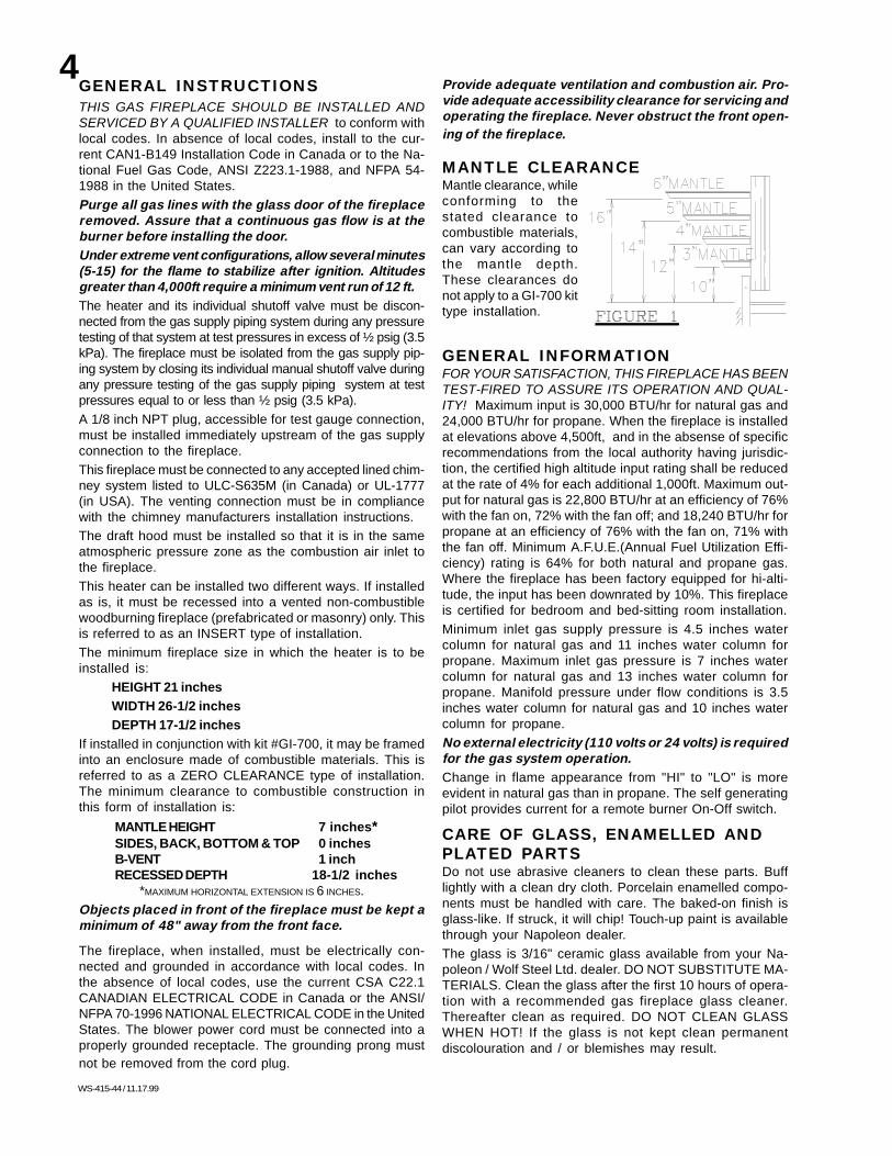
MANTLE CLEARANCEMantle clearance, whileconforming to thestated clearance tocombustible materials,can vary according tothe mantle depth.These clearances donot apply to a GI-700 kittype installation.
GENERAL INFORMATIONFOR YOUR SATISFACTION, THIS FIREPLACE HAS BEENTEST-FIRED TO ASSURE ITS OPERATION AND QUAL-ITY! Maximum input is 30,000 BTU/hr for natural gas and24,000 BTU/hr for propane. When the fireplace is installedat elevations above 4,500ft, and in the absense of specificrecommendations from the local authority having jurisdic-tion, the certified high altitude input rating shall be reducedat the rate of 4% for each additional 1,000ft. Maximum out-put for natural gas is 22,800 BTU/hr at an efficiency of 76%with the fan on, 72% with the fan off; and 18,240 BTU/hr forpropane at an efficiency of 76% with the fan on, 71% withthe fan off. Minimum A.F.U.E.(Annual Fuel Utilization Effi-ciency) rating is 64% for both natural and propane gas.Where the fireplace has been factory equipped for hi-alti-tude, the input has been downrated by 10%. This fireplaceis certified for bedroom and bed-sitting room installation.
Minimum inlet gas supply pressure is 4.5 inches watercolumn for natural gas and 11 inches water column forpropane. Maximum inlet gas pressure is 7 inches watercolumn for natural gas and 13 inches water column forpropane. Manifold pressure under flow conditions is 3.5inches water column for natural gas and 10 inches watercolumn for propane.
No external electricity (110 volts or 24 volts) is requiredfor the gas system operation.Change in flame appearance from "HI" to "LO" is moreevident in natural gas than in propane. The self generatingpilot provides current for a remote burner On-Off switch.
CARE OF GLASS, ENAMELLED ANDPLATED PARTSDo not use abrasive cleaners to clean these parts. Bufflightly with a clean dry cloth. Porcelain enamelled compo-nents must be handled with care. The baked-on finish isglass-like. If struck, it will chip! Touch-up paint is availablethrough your Napoleon dealer.
The glass is 3/16" ceramic glass available from your Na-poleon / Wolf Steel Ltd. dealer. DO NOT SUBSTITUTE MA-TERIALS. Clean the glass after the first 10 hours of opera-tion with a recommended gas fireplace glass cleaner.Thereafter clean as required. DO NOT CLEAN GLASSWHEN HOT! If the glass is not kept clean permanentdiscolouration and / or blemishes may result.
GENERAL INSTRUCTIONSTHIS GAS FIREPLACE SHOULD BE INSTALLED ANDSERVICED BY A QUALIFIED INSTALLER to conform withlocal codes. In absence of local codes, install to the cur-rent CAN1-B149 Installation Code in Canada or to the Na-tional Fuel Gas Code, ANSI Z223.1-1988, and NFPA 54-1988 in the United States.
Purge all gas lines with the glass door of the fireplaceremoved. Assure that a continuous gas flow is at theburner before installing the door.Under extreme vent configurations, allow several minutes(5-15) for the flame to stabilize after ignition. Altitudesgreater than 4,000ft require a minimum vent run of 12 ft.The heater and its individual shutoff valve must be discon-nected from the gas supply piping system during any pressuretesting of that system at test pressures in excess of ½ psig (3.5kPa). The fireplace must be isolated from the gas supply pip-ing system by closing its individual manual shutoff valve duringany pressure testing of the gas supply piping system at testpressures equal to or less than ½ psig (3.5 kPa).
A 1/8 inch NPT plug, accessible for test gauge connection,must be installed immediately upstream of the gas supplyconnection to the fireplace.
This fireplace must be connected to any accepted lined chim-ney system listed to ULC-S635M (in Canada) or UL-1777(in USA). The venting connection must be in compliancewith the chimney manufacturers installation instructions.
The draft hood must be installed so that it is in the sameatmospheric pressure zone as the combustion air inlet tothe fireplace.
This heater can be installed two different ways. If installedas is, it must be recessed into a vented non-combustiblewoodburning fireplace (prefabricated or masonry) only. Thisis referred to as an INSERT type of installation.
The minimum fireplace size in which the heater is to beinstalled is:
HEIGHT 21 inches
WIDTH 26-1/2 inches
DEPTH 17-1/2 inches
If installed in conjunction with kit #GI-700, it may be framedinto an enclosure made of combustible materials. This isreferred to as a ZERO CLEARANCE type of installation.The minimum clearance to combustible construction inthis form of installation is:
MANTLE HEIGHT 7 inches*SIDES, BACK, BOTTOM & TOP 0 inchesB-VENT 1 inchRECESSED DEPTH 18-1/2 inches
*MAXIMUM HORIZONTAL EXTENSION IS 6 INCHES.
Objects placed in front of the fireplace must be kept aminimum of 48" away from the front face.
The fireplace, when installed, must be electrically con-nected and grounded in accordance with local codes. Inthe absence of local codes, use the current CSA C22.1CANADIAN ELECTRICAL CODE in Canada or the ANSI/NFPA 70-1996 NATIONAL ELECTRICAL CODE in the UnitedStates. The blower power cord must be connected into aproperly grounded receptacle. The grounding prong mustnot be removed from the cord plug.
5
WS-415-44 /11.17.99
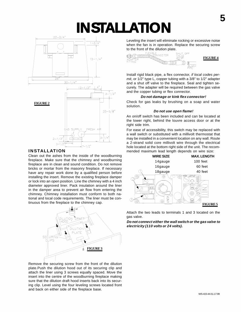
Leveling the insert will eliminate rocking or excessive noisewhen the fan is in operation. Replace the securing screwto the front of the dilution plate.
Install rigid black pipe, a flex connector, if local codes per-mit, or 1/2" type L, copper tubing with a 3/8" to 1/2" adapterand a shut off valve to the fireplace. Seal and tighten se-curely. The adapter will be required between the gas valveand the copper tubing or flex connector.
Do not damage or kink flex connector!Check for gas leaks by brushing on a soap and watersolution.
Do not use open flame!An on/off switch has been included and can be located atthe lower right, behind the louvre access door or at theright side trim.
For ease of accessibility, this switch may be replaced witha wall switch or substituted with a millivolt thermostat thatmay be installed in a convenient location on any wall. Routea 2-strand solid core millivolt wire through the electricalhole located at the bottom right side of the unit. The recom-mended maximum lead length depends on wire size:
WIRE SIZE MAX. LENGTH
14gauge 100 feet
16gauge 60 feet
18gauge 40 feet
Attach the two leads to terminals 1 and 3 located on thegas valve.
Do not connect either the wall switch or the gas valve toelectricity (110 volts or 24 volts).
INSTALLATIONClean out the ashes from the inside of the woodburningfireplace. Make sure that the chimney and woodburningfireplace are in clean and sound condition. Do not removebricks or mortar from the masonry fireplace. If necessaryhave any repair work done by a qualified person beforeinstalling the insert. Remove the existing fireplace damperor lock into an open position. Line the chimney with a 4 inchdiameter approved liner. Pack insulation around the linerin the damper area to prevent air flow from entering thechimney. Chimney installation must conform to both na-tional and local code requirements. The liner must be con-tinuous from the fireplace to the chimney cap.
Remove the securing screw from the front of the dilutionplate.Push the dilution hood out of its securing clip andattach the liner using 3 screws equally spaced. Move theinsert into the centre of the woodburning fireplace makingsure that the dilution draft hood inserts back into its secur-ing clip. Level using the four leveling screws located frontand back on either side of the fireplace base.
INSTINSTINSTINSTINSTALLAALLAALLAALLAALLATIONTIONTIONTIONTION
FIGURE 2
FIGURE 3
FIGURE 4
FIGURE 5
6
WS-415-44 / 11.17.99
FIGURE 8
FIGURE 6
FIGURE 7
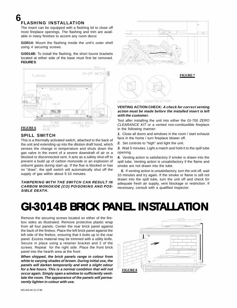
SPILL SWITCHThis is a thermally activated switch, attached to the back ofthe unit and extending up into the dilution draft hood, whichsenses the change in temperature and shuts down thegas valve in the event of a severe downdraft of air or ablocked or disconnected vent. It acts as a safety shut-off toprevent a build up of carbon monoxide or an explosion ofunburnt gases during start up. If the flue is blocked or hasno "draw", the spill switch will automatically shut off thesupply of gas within about 5-10 minutes.
TAMPERING WITH THE SWITCH CAN RESULT INCARBON MONOXIDE (CO) POISONING AND POS-SIBLE DEATH.
FLASHING INSTALLATIONThe insert can be equipped with a flashing kit to close offmost fireplace openings. The flashing and trim are avail-able in many finishes to accent any room decor.
GI3014: Mount the flashing inside the unit's outer shellusing 4 securing screws.
GI3014B: To install the flashing, the short louvre bracketslocated at either side of the base must first be removed.FIGURE 9.
VENTING ACTION CHECK: A check for correct ventingaction must be made before the installed insert is leftwith the customer.Test after installing the unit into either the GI-700 ZEROCLEARANCE KIT or a vented non-combustible fireplacein the following manner:
1. Close all doors and windows in the room / start exhaustfans in the home / turn fireplace blower off.
2. Set controls to "high" and light the unit.
3. Wait 5 minutes. Light a match and hold it to the spill tubeopening.
4. Venting action is satisfactory if smoke is drawn into thespill tube. Venting action is unsatisfactory if the flame andsmoke are not drawn into the tube.
5. If venting action is unsatisfactory, turn the unit off, wait10 minutes and try again. If the smoke or flame is still notdrawn into the spill tube, turn the unit off and check foradequate fresh air supply, vent blockage or restriction. Ifnecessary, consult with a qualified inspector.
GI-3014B BRICK PGI-3014B BRICK PGI-3014B BRICK PGI-3014B BRICK PGI-3014B BRICK PANEL INSTANEL INSTANEL INSTANEL INSTANEL INSTALLAALLAALLAALLAALLATIONTIONTIONTIONTIONRemove the securing screws located on either of the fire-box sides as illustrated. Remove protective plastic wrapfrom all four panels. Center the rear brick panel againstthe back of the firebox. Place the left brick panel against theleft side of the firebox, ensuring that it butts up to the rearpanel. Excess material may be trimmed with a utility knife.Secure in place using a retainer bracket and 2 of thescrews. Repeat for the right side. Place the front brickpanel into the hearth area at the front.
When shipped, the brick panels range in colour fromwhite to varying shades of brown. During initial use, thepanels will darken temporarily and emit a slight odourfor a few hours. This is a normal condition that will notoccur again. Simply open a window to sufficiently venti-late the room. The appearance of the panels will perma-nently lighten in colour with use.

7
WS-415-44 /11.17.99
SKEWERINGSCREW
FIGURE 9
FIGURE 10
FINISHINGFINISHINGFINISHINGFINISHINGFINISHINGPOSITIONING THE LOGS IMPROPERLY WILL CAUSE
FLAME IMPINGEMENT AND CARBONING.
LOG PLACEMENT INSTRUCTIONS /CHARCOAL EMBERSPHAZERTM logs and charcoal embers, exclusive to Napo-leon Fireplaces, provide a unique and realistic glowingeffect that is different in every installation. Take the time tocarefully position the charcoal embers for a maximum glow-ing effect.
CHARCOAL EMBERS: Randomly place the embers be-neath the front log, covering all of the burner area beneaththe hollowed out section of the log. Place the remainingembers along the front. Keep ember dust away from burnerports to avoid plugging them.
Fine dust found in bottom of bag not to be used.PHAZERTM logs and charcoal embers glow when exposedto direct flame. Use only certified PHAZERTM logs and char-coal embers available from your Napoleon / Wolf Steel Ltd.dealer.
1. Place the front log onto the main burner, pushing itas close as possible to the burner ports withoutblocking/covering them. The left and right spacing betweenthe log ends and the burner ports should be equal.
YOU MAY FIND IT EASIER TO PLACE SOME CHARCOALEMBERS BENEATH THE FRONT LOG NOW.
2. Place the back log onto the log support bracketslocated on the rear wall of the combustion chamber. Thenotch situated at the lower left of the back log should becentered evenly above the pilot assembly.
3. While supporting the back log, to prevent it fromfalling forward, set the three smaller logs into the pocketsand grooves of the front and back logs, respectively.
Log colours may vary. During the initial use of the fire-place, the colours will become more uniform as colourpigments burn in during the heat activated curing proc-ess.

8
WS-415-44 / 11.17.99
FIGURE 13
FIGURES 11FIGURE 12
GI-3014B: In order to access the interior of the firebox,remove the two screws located below the upper louvreassembly and the two screws located to either side be-tween the first and second lower side louvre. Lift out thebay frame assembly. Install the louvres and louvre as-semblies as illustrated. Attach the decorative (magnetic)upper glass bracket.
DOOR & LOUVRE INSTALLATIONGI-3014: In order to access the interior of the firebox, re-move two screws holding the upper glass bracket cover,and the upper glass bracket in place and the two screwsholding the lower glass bracket. The louvre assembliesare installed as illustrated. The upper glass bracket coveris formed with tabs to create a gap for air flow and must notbe adjusted.
UPPER LOUVRES - 3 PC SET
A
BC
FIGURE A FIGURE B
FIGURES C
OPERAOPERAOPERAOPERAOPERATION / MAINTENANCETION / MAINTENANCETION / MAINTENANCETION / MAINTENANCETION / MAINTENANCEFRESH AIR DAMPER SYSTEMIf your masonry fireplace is equipped with a fresh air inletin the floor of the firebrick chamber, the insert is able totake outside air directly into the unit through an opening inits base thereby eliminating the need to use preheatedroom air for combustion. The flow of air may be adjustedthrough the use of a damper located below the louvre ac-cess door. The damper should be kept closed (pushed allthe way in) when the unit is not in operation or if no outsideair is available. The damper is fully open when pulled for-ward (one inch from the closed position).
Never obstruct the flow of combustion orventilation air.

9
WS-415-44 /11.17.99
Simply open a window to sufficiently ventilate the room.After extended periods of non-operation such as followinga vacation or a warm weather season, the fireplace mayemit a slight odour for a few hours. This is caused by dustparticles in the heat exchanger burning off. Open a windowto sufficiently ventilate the room.
OPERATING INSTRUCTIONSWhen lit for the first time, the stove will emit a slight odourfor a few hours. This is a normal temporary conditioncaused by the curing of the logs and the "burn-in" of inter-nal paints and lubricants used in the manufacturing proc-ess and will not occur again.
Call a qualified service technician. Force or attemptedrepair may result in a fire or explosion.
D Do not use this insert if any part has been under water.Immediately call a qualified service technician to inspectthe unit and replace any part of the control system andany gas control touched by water.
FOR YOUR SAFETY READ BEFORE OPERATING
A This stove has a pilot which must be lit by hand whilefollowing these instructions exactly.
B Before lighting, smell all around the firplace area forgas and next to the floor because some gas is heavierthan air and will settle on the floor.
C Use only your hand to push in or turn the gas controlknob. Never use tools. If the knob will not push in or turnby hand, do not try to repair it.
• Immediately call your gas supplier from a neighbour'sphone. Follow the gas supplier's instructions.
• If you cannot reach your gas supplier, call the fire de-partment.
WHAT TO DO IF YOU SMELL GAS:
• Do not try to light any appliance.
• Do not touch any electrical switch; do not use any phonein your building.
8.Depress and hold the gas knob while lighting the pilotwith the push button ignitor. Keep the knob fully de-pressed for one (1) minute, then release. If the pilot doesnot continue to burn, repeat steps 3 through 7.9.With the pilot lit, turn the gas knob counter-clock-
wise to "on" position.
10.If your insert is equipped with a flame adjustmentvalve, push and turn the knob to "high".11.If your insert is equipped with a remote "on-off" switch,the main burner may not come on when you turn the gasvalve to "on" or "high". The remote switch must be in the"on" position as well to ignite the main burner.12.Turn on all electrical power to the insert.
LIGHTING INSTRUCTIONS:
1.Stop! Read all the safety information above. When light-ing and re-lighting, the gas knob cannot be turned from"pilot" to "off" unless the knob is depressed.2.Turn off all electrical power to the stove.3.Turn the gas knob clockwise to off.4.Wait 5 minutes for any gas in the combustion chamberto escape. Continue to the next step if you do NOT smellany gas. If you smell gas, STOP! and follow the instruc-tions in "What to do if You Smell Gas" listed above.5.If the unit is equipped with a flame adjustment valve,turn clockwise to off.6.Locate the pilot situated in front of the rear log.
7.Turn the gas knob counter-clockwise to "pi-
lot" position.
2.Push in gas control knob slightly and turn clock-wise to off. Do not force.
INSTRUCTIONS TO TURN OFF GAS:
1.Turn off all electrical power to the unit if service isto be performed.
3. Check to see that all burner ports are burning. Clean outany of the ports which may not be burning or are not burn-ing properly. (right brick panel must be removed in order tofacilitate burner removal)
4. Check to see that the pilot flame is large enough toengulf the thermopile on one leg and reaches toward theburner on the other leg.
5. Replace the cleaned logs.
6. Check to see that the main burner ignites completely onall openings when the gas knob for the burner is turnedon. A 5 to 10 second total light-up period is satisfactory. Ifignition takes longer, consult your Napoleon dealer / dis-tributor.
7. Check that the gasketing on the door is not broken ormissing. Replace if necessary.
MAINTENANCE SEE FIGURE 18 TURN TURN TURN TURN TURNOFF THE GAS AND ELECTRICAL POWEROFF THE GAS AND ELECTRICAL POWEROFF THE GAS AND ELECTRICAL POWEROFF THE GAS AND ELECTRICAL POWEROFF THE GAS AND ELECTRICAL POWERBEFORE SERVICING THE FIREPLACE.BEFORE SERVICING THE FIREPLACE.BEFORE SERVICING THE FIREPLACE.BEFORE SERVICING THE FIREPLACE.BEFORE SERVICING THE FIREPLACE.CAUTION: Label all wires prior to disconnection when serv-icing controls. Wiring errors can cause improper and dan-gerous operation. Verify proper operation after servicing.This insert and its venting system should be inspectedbefore use and at least annually by a qualified service per-son. The fireplace area must be kept clear and free ofcombustible materials, gasoline or other flammable va-pours and liquids. The flow of combustion and ventilationair must not be obstructed.
1. In order to properly clean the burner and pilot assembly,remove the logs to expose both assemblies.
2. Keep the control compartment, logs, burner, air shutteropening and the area surrounding the logs clean by vacu-uming or brushing, at least once a year.
THERMOPILE
ELECTRODE
PILOT BURNER
GAS VALVE
10
WS-415-44 / 11.17.99
FIGURE 15FIGURE 17
FIGURE 16
FIGURE 14
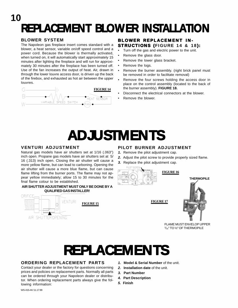
BLOWER SYSTEMThe Napoleon gas fireplace insert comes standard with ablower, a heat sensor, variable on/off speed control and apower cord. Because the blower is thermally activated,when turned on, it will automatically start approximately 15minutes after lighting the fireplace and will run for approxi-mately 30 minutes after the fireplace has been turned off.Use of the fan increases the output of heat. Air, drawn inthrough the lower louvre access door, is driven up the backof the firebox, and exhausted as hot air between the upperlouvres.
REPLACEMENT BLOWER INSTREPLACEMENT BLOWER INSTREPLACEMENT BLOWER INSTREPLACEMENT BLOWER INSTREPLACEMENT BLOWER INSTALLAALLAALLAALLAALLATIONTIONTIONTIONTION
ADJUSTMENTSADJUSTMENTSADJUSTMENTSADJUSTMENTSADJUSTMENTS
BLOWER REPLACEMENT IN-BLOWER REPLACEMENT IN-BLOWER REPLACEMENT IN-BLOWER REPLACEMENT IN-BLOWER REPLACEMENT IN-STRUCTIONS (STRUCTIONS (STRUCTIONS (STRUCTIONS (STRUCTIONS (FIGURE 14 & 18):):):):):• Turn off the gas and electric power to the unit.
• Remove the glass door.
• Remove the lower glass bracket.
• Remove the logs.
• Remove the burner assembly. (right brick panel mustbe removed in order to facilitate removal)
• Remove the four screws holding the access door inplace on the control assembly (located to the back ofthe burner assembly). FIGURE 18.
• Disconnect the electrical connectors at the blower.
• Remove the blower.
PILOT BURNER ADJUSTMENT1. Remove the pilot adjustment cap.
2. Adjust the pilot screw to provide properly sized flame.
3. Replace the pilot adjustment cap.
VENTURI ADJUSTMENTNatural gas models have air shutters set at 1/16 (.063")inch open. Propane gas models have air shutters set at 5/16 (.313) inch open. Closing the air shutter will cause amore yellow flame, but can lead to carboning. Opening theair shutter will cause a more blue flame, but can causeflame lifting from the burner ports. The flame may not ap-pear yellow immediately; allow 15 to 30 minutes for thefinal flame colour to be established.
AIR SHUTTER ADJUSTMENT MUST ONLY BE DONE BY AQUALIFIED GAS INSTALLER!
ORDERING REPLACEMENT PARTSContact your dealer or the factory for questions concerningprices and policies on replacement parts. Normally all partscan be ordered through your Napoleon dealer or distribu-tor. When ordering replacement parts always give the fol-lowing information:
REPLACEMENTSREPLACEMENTSREPLACEMENTSREPLACEMENTSREPLACEMENTS1. Model & Serial Number of the unit.
2. Installation date of the unit.
3. Part Number
4. Part Description
5. Finish
FLAME MUST ENVELOP UPPER3/16" TO ½" OF THERMOPILE
THERMOPILE

11
WS-415-44 /11.17.99
REPLACEMENT PARTS LISTPART NO. DESCRIPTION
COMMON PARTSGZ-551 REPLACEMENT BLOWERWS-725-13 NATURAL GAS VALVEGA-GI-010.168 PROPANE GAS VALVEWS-010-175 LP HI-LO VALVEWS-010-87 NG HI-LO VALVEWS 455-04 #36 DMS NATURAL GAS BURNER ORIFICEWS 455-03 #54 DMS PROPANE GAS BURNER ORIFICEWS 455-13 #37 DMS NATURAL GAS BURNER ORIFICE - HIALTWS 455-02 #55 DMS PROPANE GAS BURNER ORIFICE - HIALTWS 380-1 FLAME ADJUSTMENT VALVE KNOBWS 660-7 SPILL SWITCH (NATURAL GAS)WS 660-6 SPILL SWITCH (PROPANE GAS)GA-GI-010.337 NATURAL GAS PILOT ASSEMBLYGA-GI-010.338 PROPANE GAS PILOT ASSEMBLYWS-357-01 PIEZO IGNITERWS-680-01 THERMOPILEWS-690-02 THERMAL SENSING SWITCHGI 707K UPPER LOUVRE ASS'Y - BLACKGI 707G UPPER LOUVRE ASS'Y- 24K GOLD PLATEGI 941B6 "MARQUIS" TRIM - SATIN BRASS FOR 6" FLASHINGSGI 941B9 "MARQUIS" TRIM - SATIN BRASS FOR 9" FLASHINGSWS-660-09 BURNER ON/OFF SWITCHGA GI 135.07 BACK LOGGA GI 135.052 FRONT LOGGA GI 135.10 RIGHT LOGGA GI 135.09 CENTER LOGGA GI 135.08 LEFT LOGGL-610 LOG SET c/w CHARCOAL EMBERSGA GI 550.01 CHARCOAL EMBERSGA GI 10.333 BURNER ASSEMBLYWS 455-5 NATURAL GAS PILOT ORIFICEWS 455-6 PROPANE GAS PILOT ORIFICEGI 945AB-6 ANTIQUE BRASS FLASHINGS - 6"GI 945B-6 POLISHED BRASS FLASHINGS - 6"GI 945C-6 CHROME FLASHINGS - 6"GI 945K-6 BLACK FLASHINGS - 6"GI 950S-6 ALMOND ENAMEL FLASHINGS - 6"GI 950B-6 BLUE ENAMEL FLASHINGS - 6"GI 950K-6 BLACK ENAMEL FLASHINGS - 6"GI 950F-6 GREEN ENAMEL FLASHINGS - 6"GI 945AB-9 ANTIQUE BRASS FLASHINGS - 9"GI 945B-9 POLISHED BRASS FLASHINGS - 9"GI 945C-9 CHROME FLASHINGS - 9"GI 945K-9 BLACK FLASHINGS - 9"GI 950S-9 ALMOND ENAMEL FLASHINGS - 9"GI 950B-9 BLUE ENAMEL FLASHINGS - 9"GI 950K-9 BLACK ENAMEL FLASHINGS - 9"GI 950F-9 GREEN ENAMEL FLASHINGS - 9"WS-385-33 NAPOLEON LOGOKB 35 VARIABLE SPEED SWITCH
GI3014WS-300-12 DOOR GLASSGA-GI-562.012 DOOR GASKET (2PC - SIDE)GA-GI-562.011 DOOR GASKET - TOPGI 200B UPPER GLASS BRACKET COVER - POL. BRASSGI 200AB UPPER GLASS BRACKET COVER - ANT. BRASSGI 200C UPPER GLASS BRACKET COVER - CHROMEGA-GI-080.62 UPPER GLASS BRACKETGA-GI-080.79 LOWER GLASS BRACKETGI 708PB LOWER LOUVRE ASS'Y - POLISHED BRASSGI 708AB LOWER LOUVRE ASS'Y- ANTIQUE BRASSGI 708C LOWER LOUVRE ASS'Y - CHROMEGI 708G LOWER LOUVRE ASS'Y - 24K GOLD PLATEGI 941K6 1" TRIM - BLACK FOR 6" FLASHINGSGI 941K9 1" TRIM - BLACK FOR 9" FLASHINGS
GI3014BGI 808PB LOWER LOUVRE ASS'Y - POLISHED BRASSGI 808AB LOWER LOUVRE ASS'Y- ANTIQUE BRASSGI 808G LOWER LOUVRE ASS'Y - 24K GOLD PLATEGA GI 010.336 BAY FRAME ASS'Y C/W GASKETGA GI 010.326 FRONT GLASS C/W GASKETGA-GI 010.325 SIDE GLASS C/W GASKETGI 201AB BAY DOOR TRIM - ANTIQUE BRASSGI201B BAY DOOR TRIM - POLISHED BRASSGI 778KT BRICK PANEL KIT
GL-610

12
WS-415-44 / 11.17.99
111KTWS-690-01
GI 700KT
GD240-K
ACCESSORIES / OPTIONSPART NO. DESCRIPTION
COMMON PARTSGI 778KT BRICK VENEER KITWS 470-2 ENAMEL TOUCH UP AND BRUSH (SPECIFY COLOUR)GI 700KT ZERO CLEARANCE SHELL111-KT OUTSIDE AIR KITWS 690-1 MILLIVOLT THERMOSTATWS 660-2 HANDHELD REMOTE CONTROLWS-660-010 REMOTE CONTROL - ADVANTAGE
WS-660-011 REMOTE CONTROL - ADVANTAGE PLUS
GD 660 WALL SWITCH/20FT WIREWS 500-33 V.S.S. MOUNTING PLATE FOR WALL SWITCH
GI3014GI 709G GOLD PLATED LOUVRESGI 940B-6 6" FLASHING KIT - POLISHED BRASSGI 940AB-6 6" FLASHING KIT - ANTIQUE BRASSGI 940K-6 6" FLASHING KIT - BLACKGI 940C-6 6" FLASHING KIT - CHROMEGI 940B-9 9" FLASHING KIT - POLISHED BRASSGI 940AB-9 9" FLASHING KIT - ANTIQUE BRASSGI 940K-9 9" FLASHING KIT - BLACKGI 940C-9 9" FLASHING KIT - CHROMEGI 960S-6 6" PORCELAIN FLASHING KIT - ALMONDGI 960B-6 6" PORCELAIN FLASHING KIT - BLUEGI 960K-6 6" PORCELAIN FLASHING KIT - BLACKGI 960F-6 6" PORCELAIN FLASHING KIT - GREENGI 960S-9 9" PORCELAIN FLASHING KIT - ALMONDGI 960B-9 9" PORCELAIN FLASHING KIT - BLUEGI 960K-9 9" PORCELAIN FLASHING KIT - BLACKGI 960F-9 9" PORCELAIN FLASHING KIT - GREENGD240-K WEBBED DOOR FACIA
GI3014BGI 809-G GOLD PLATED LOUVRESGI949B-6 6" FLASHING KIT - POLISHED BRASSGI 949AB-6 6" FLASHING KIT - ANTIQUE BRASSGI 949K-6 6" FLASHING KIT - BLACKGI 949B-9 9" FLASHING KIT - POLISHED BRASSGI 949AB-9 9" FLASHING KIT - ANTIQUE BRASSGI 949K-9 9" FLASHING KIT - BLACKGI 969S-6 6" PORCELAIN FLASHING KIT - ALMONDGI 969B-6 6" PORCELAIN FLASHING KIT - BLUEGI 969K-6 6" PORCELAIN FLASHING KIT - BLACKGI 969F-6 6" PORCELAIN FLASHING KIT - GREENGI 969S-9 9" PORCELAIN FLASHING KIT - ALMONDGI 969B-9 9" PORCELAIN FLASHING KIT - BLUEGI 969K-9 9" PORCELAIN FLASHING KIT - BLACKGI 969F-9 9" PORCELAIN FLASHING KIT - GREEN
GI-778KT
GA-GI-475.142
GA-GI-475.145
GA-GI-475.144

13
WS-415-44 /11.17.99
SYMPTOM PROBLEM TEST SOLUTION
BEFORE ATTEMPTING TO TROUBLE SHOOT, PURGE YOUR UNIT AND INITIALLY LIGHT THE PILOT AND THE MAIN BURNER WITH THE GLASS DOOR REMOVED.
TROUBLE SHOOTING GUIDETROUBLE SHOOTING GUIDETROUBLE SHOOTING GUIDETROUBLE SHOOTING GUIDETROUBLE SHOOTING GUIDE
Gas piping is undersized.Pilot goes out whilestanding; Main burneris in 'OFF' position.
- turn on all gas appliances and see if pilot flame flutters,diminishes or extinguishes, especially when main burnersignite. Monitor supply pressure.- check if supply piping size is to code. Correct all under-sized piping.
Pilot goes out when thegas knob is released.
A - System is not correctlypurged.
- purge the gas line with the glass door removed.
- fill the tank and purge the gas line with the glass doorremoved.
B - Out of propane gas.
- turn up the pilot flame.
D - Pilot flame is not engulfingthe thermopile.
- gently twist the pilot head to improve the flame patternaround the thermopile.
E - Thermopile shorting. - clean thermopile and valve connection.- check that thermopile insulation is not frayed and ground-ing out on the housing or the burner support.- replace thermopile.- replace valve.
F - Faulty thermopile. - test & replace if necessary.G - Faulty valve. - test & replace if necessary.
C - Pilot flame is notlarge enough
Pilot burning; no gas tomain burner; gas knobis on; wall switch is on;heat/flame adjustmentvalve is on (if soequipped.
A - Wall switch is defective - connect a jumper wire across the wall switch terminals;if the main burner lights, replace the wall switch.
B - Wall switch wiring is defec-tive.
- disconnect switch wires from valve and connect a jumperwire across terminals 1 and 3; if the main burner lights,check the wires for defects and/or replace wires.
C- Main burner orif ice isplugged.
- remove stoppage in orifice.
D - Remote gas valve operatoris defective.
- connect a jumper wire across terminals 1 and 3; if mainburner does not light, replace gas valve.
- fill the tank and purge the gas line with the glass doorremoved.
Pilot will not light. - check that the wire is connected to the push button ignitor.- check if the push button ignitor needs tightening.- replace pilot assembly if the wire insulation is broken orfrayed.- replace pilot assembly if the ceramic insulator is crackedor broken.- replace the push button ignitor.
A - No spark at pilot burner
B - Spark gap is incorrect - spark gap should be 1/16" to 1/8" from the electrode tipand the pilot burner. Light the pilot with a match and adjustthe electrode tip to the required spark gap and proper loca-tion.
C - No gas at the pilot burner - check that the manual valve is turned on.- check the pilot orifice for blockage.- replace the valve.- call the gas distributor.
D - Out of propane gasTHERMO-PILE
P I L O TBURNER
P I E Z OIGNITER
1/16" TO 1/8"

14
WS-415-44 / 11.17.99
SYMPTOM TEST SOLUTIONPROBLEM
Main burner goes out;pilot goes out.
A - Refer to "Main burner goes out; pilot stays on"
B - Chimney down-drafting - wait ten minutes. Shut off all exhaust fans in the house(ie: kitchen and bathrooms), furnace, and clothes dryer.Open windows and/or doors. Start fireplace and monitor itsoperation.
Close doors and windows and start appliances as before;room is in negative pressure; increase fresh air supply.
C - Chimney is blocked - check for chimney blockage.
D - Liner disconnected from in-sert.
- re-attach liner.
E - Faulty spill switch. - replace.
Carbon is being de-posited on glass, logsor combustion cham-ber surfaces. Flame is impinging on the logs
or combustion chamber.- check that the logs are correctly positioned.- open air shutter to increase the primary air.- check the input rate: check the manifold pressure andorifice size as specified by the rating plate values.- check that the door gasketing is not broken or missingand that the seal is tight.- check that the 4" vent liner is free of holes and well sealedat all joints.- check that minimum rise per foor has been adhered to forany horizontal venting.
Air shutter has become blocked - ensure air shutter opening is free of lint or other obstruc-tions.
Exhaust fumessmelled in room, head-aches.
- check for chimney blockage.- check that chimney is installed to building code.- room is in negative pressure; increase fresh air supply.
Fireplace is spilling.
A - Wall switch is mounted up-side down.
B - Remote wall switch isgrounding.
C - Remote wall switch wire isgrounding.
Remote wall switch isin off position; mainburner comes onwhen gas knob isturned to "ON" posi-tion.
- reverse.
- replace.
- check for ground (short); repair ground or replace wire.
D - Faulty valve. - replace.
Main burner flame is ablue, lazy, transparentflame.
A - Insufficient secondary air. - increase fresh air supply (open door, window, add make-up air supply)
B - Downdraft or blockage inchimney.
- remove blockage.- check that chimney is installed to building codes (3ftabove highest roof line or 2ft higher than any portion of abuilding within a horizontal radius of 10ft of the chimney.)
B - Thermopile shorting.
A - Pilot flame is not largeenough or not engulfing the ther-mopile.
Main burner goes out;pilot stays on.
- turn on pilot flame. Gently twist the pilot head to improvethe flame pattern aroung the thermopile.
- clean thermopile and thermopile connection to valve.
White / grey film forms. Sulphur from fuel is being de-posited on glass, logs or com-bustion chamber surfaces.
- clean the glass with a gas fireplace glass cleaner. DONOT CLEAN GLASS WHEN HOT.If deposits are not cleaned off regularly, the glass may be-come permanently marked.

15
WS-415-44 /11.17.99
NOTES:NOTES:NOTES:NOTES:NOTES: