Gas Fireplace Inserts - Installation and Operating...
37
OSBURN CORDOVA SERIES Gas Fireplace Inserts - Installation and Operating Instructions WARNING: If the information in this manual is not followed exactly, a fire or explosion may result causing property damage, personal injury or loss of life. FOR YOUR SAFETY Do not store or use gasoline, or other flammable vapours and liquids, in the vicinity of this, or any other appliance. WHAT TO DO IF YOU SMELL GAS • Open windows • Extinguish any open flame • Do not try to light any appliance • Do not touch any electrical switch • Do not use any phone in your building • Immediately call your gas supplier from a neighbour's phone. Follow the gas supplier's instructions. • If you cannot reach your gas supplier call the fire department. WARNING Improper installation, service, adjustment, alteration, or maintenance can cause injury or property damage. Refer to this manual. For assistance or additional information, consult a qualified installer, service agency, or the gas supplier. Please read this manual before installing or using this appliance. Retain this manual for future reference. Patents Pending Made in Canada 06/05/02 KA1125
Transcript of Gas Fireplace Inserts - Installation and Operating...

OSBURN CORDOVA SERIES Gas Fireplace Inserts - Installation and Operating Instructions
WARNING: If the information in this manual is not followed exactly, a fire or explosion may result causing property damage, personal injury or loss of life. FOR YOUR SAFETY Do not store or use gasoline, or other flammable vapours and liquids, in the vicinity of this, or any other appliance. WHAT TO DO IF YOU SMELL GAS
• Open windows • Extinguish any open flame • Do not try to light any appliance • Do not touch any electrical switch • Do not use any phone in your building • Immediately call your gas supplier from a neighbour's phone. Follow the gas supplier's instructions. • If you cannot reach your gas supplier call the fire department.
WARNING Improper installation, service, adjustment, alteration, or maintenance can cause injury or property damage. Refer to this manual. For assistance or additional information, consult a qualified installer, service agency, or the gas supplier.
Please read this manual before installing or using this appliance. Retain this manual for future reference.
Patents Pending Made in Canada
06/05/02 KA1125

T ABLE OF CONTENTS 1.0 Introduction ....................................................................................................................................................................... 3
1.1 Specifications ........................................................................................................................................................ 3 1.2 Features .................................................................................................................................................................. 5 1.3 Intended Use........................................................................................................................................................... 5 1.4 General Safety ........................................................................................................................................................ 6
2.0 Operation............................................................................................................................................................................ 7
2.1 Operation Safety ..................................................................................................................................................... 7 2.2 Lighting Instructions............................................................................................................................................... 8 2.3 Heat Output Adjustment ....................................................................................................................................... 10 2.4 Fan Operation ....................................................................................................................................................... 10 2.5 Remote Control Operation.................................................................................................................................... 10
3.0 Installation........................................................................................................................................................................ 11
3.1 Installation & Safety Notes................................................................................................................................... 11 3.2 Unpacking ............................................................................................................................................................ 11 3.3 Installation ............................................................................................................................................................ 11
3.3.1 Minimum Clearances To Combustible Construction................................................................................. 12 3.3.2 Chimney Liner Or Vent Installation .......................................................................................................... 14 3.3.3 Gas Line Installation.................................................................................................................................. 15 3.3.4 Thermostat, Wall Switch, Or Remote Control Installation...................................................................... 16 3.3.5 Vent, Gas Line, & Wiring Connections..................................................................................................... 18 3.3.6 Lower Grille Installation ........................................................................................................................... 19 3.3.7 Faceplate Installation................................................................................................................................. 20 3.3.8 Firebox Component Installation ................................................................................................................ 22
3.3.8.1 Log-Set Installation ......................................................................................................................... 22 3.3.8.2 Coal and Ember Placement.............................................................................................................. 23 3.3.8.3 Installing the Lower Door Trim....................................................................................................... 24 3.3.8.4 Installing the Door........................................................................................................................... 25 3.3.8.5 Installing the Vertical Trims (Contemporary Grille Kits Only)....................................................... 25 3.3.8.6 Installing the Top Grille Assembly ................................................................................................. 25
3.3.9 Initial Firing............................................................................................................................................... 26 3.3.9.1 Manifold Pressure Regulator Adjustment ....................................................................................... 26 3.3.9.2 Pilot Flame Adjustment ................................................................................................................... 26 3.3.9.3 Flue Spillage Test............................................................................................................................ 27 3.3.9.4 Altitude Adjustment ........................................................................................................................ 27
4.0 Maintenance ......................................................................................................................................................................28
4.1 Maintenance Safety .............................................................................................................................................. 28 4.2 Recommended Service ......................................................................................................................................... 28 4.3 Glass Cleaning...................................................................................................................................................... 28 4.4 Cleaning Of Brass Plated Surfaces ....................................................................................................................... 28 4.5 Cleaning Of Gold Plated Surfaces ........................................................................................................................ 28 4.6 Burner & Pilot Cleaning ....................................................................................................................................... 29 4.7 Fan Replacement & Electrical Schematic............................................................................................................. 29 4.8 Heater Disassembly & Reassembly ...................................................................................................................... 31
5.0 Trouble Shooting...............................................................................................................................................................32
6.0 Replacement Parts ............................................................................................................................................................35
7.0 Osburn’s Warranty ..........................................................................................................................................................37
8.0 Label Information .............................................................................................................................................................39 1.0 Introduction
/2

1.1 Specifications
Table 1 Specifications
Item Natural Gas (NG) Propane (LPG) Btu Input : Maximum
25,000 Btu/hr (26.4 MJ/hr) 25,000 Btu/hr (26.4 MJ/hr) 12,500 Btu/hr ( 13.2 MJ/hr) 16,750 Btu/hr (17.6 MJ/hr)
Minimum Flue Loss: Efficiency: Fan off 70% 72% Fan on 75% 76%
Output: Fan off 17,500 Btu/hr (18.5 MJ/hr) 18,000 Btu/hr (19 MJ/hr) Fan on 18,750 Btu/hr (19.8 MJ/hr) 19,000 Btu/hr (20 MJ/hr) AFUE: Efficiency: Fan off 64% Manifold Pressure: 3.8" w.c. (0.9 kPa) 10.0" w.c. (2.5 kPa) Gas Inlet Supply Pressure: Minimum: 5.0" w.c. (1.2 kPa) Minimum: 11.0" w.c. 2.7kPa) Normal: 7.0" w.c. (1.7 kPa) Normal: 13.5" w.c. (3.4 kPa) Maximum: 13.5" w.c. (3.4
kPa) Maximum: 13.5" w.c. (3.4 kPa)
Orifice Size: #38 #52 Control Valve Type: SIT 820 Nova (50% reduction) SIT 820 Nova (33 % reduction) Shipping Weight: 80lbs 80lbs Flue Outlet Size: 4"DIA. (102mm) 4"DIA. (102mm) Fan: Variable Speed
NOTE: The efficiency rating of the appliance is a product thermal efficiency rating determined under
CONTINOUS operating conditions and was determined independently of any installed system. AFUE was tested by Manufacturer. Options: Bevelled Faceplates
Remote Control Thermostat
/3

Figure 1 Installation Codes Installation must conform to local codes. In the absence of local codes, installation must conform to the current National Fuel Gas Code, ANSI Z233.1, (in the U.S.), or with the current CAN/CGA B149.1 installation code (in Canada). In Australia, the Australian Gas Association installation code for gas burning heaters and equipment must be used. The heater, when installed, must be electrically grounded in accordance with local codes or, in the absence of local codes, with the current National Electric Code ANSI/NFPA No. 70 (in the U.S.) or with the current CSA C22.1 Canadian Electrical Code (in Canada).
/4

1.2 Features Ignition system:
Standing pilot ignition system with thermopile and thermocouple flame detection and piezo igniter.
Gas control: Gas control valve type:
Automatic millivolt powered combination gas control valve with variable flame control for convenience, and on/off switch. Optional remote on/off wall switch, optional wall thermostat, and/or optional wireless remote control are available. The gas valve does not require electricity from an external source.
Fan control:
Variable Speed Control:
For units equipped with a fan control, the knob controls the fan speed in connection with a heat sensitive switch which turns on when the heater reaches operating temperature. Turning the knob counter-clockwise turns it to the “OFF” position.
Auto/Off Switch:
For units equipped with a fan switch, the fan may be switched between the “AUTOMATIC” & the “OFF” settings.
Safety controls:
A safety switch will shut the system down in the event of any one of the following conditions:
Incorrectly installed vent system Blocked vent causing flue spillage Flow reversal or sustained down draft situation
Drafthood:
The appliance is provided with a drafthood design which minimizes the effects of down drafts or flue blockages on the quality of combustion. It will vent out of the appliance upon down draft or flue blockage and, by design, it exhausts to the same pressure zone as the combustion air inlet to the appliance. 1.3 Intended Use This appliance is intended to be used as a heater, when installed as an insert for code complying masonry, or listed factory built solid fuel burning fireplaces which meet the minimum requirements as described in detail in the installation instructions. This insert is certified for installation in a bedroom or a bed sitting room where the maximum input is within 50 cubic feet per 1000 Btu/hr, (i.e. 1250 cubic feet). All bedroom installations require the use of wall thermostats. 1.4 General Safety
/5

The appliance must be properly connected to a venting system in accordance with local codes. This unit must not be connected to a chimney or flue serving any other appliance. It is equipped with a safety control system to protect against improper venting of flue products.
WARNING: Operation of this insert when not connected to a properly installed and maintained venting system, may result in carbon monoxide poisoning.
Installation and repair should be done by a qualified service person. The appliance should be inspected before use and at least annually by a professional service technician. Provide adequate clearances around air openings and allow accessibility clearance for servicing and proper operation. In Australia, a dress guard has been installed to cover the glass and to protect users against accidental contact with hot surfaces. Do not operate the appliance without the dress guard in place.
/6

2 .0 Operation 2.1 Operation Safety Inspect the appliance before use. Always keep the appliance area clear and free from combustible materials, gasoline and other flammable vapours and liquids. Never obstruct the flow of ventilation air. Keep the front of the appliance clear of all obstacles and foreign materials. Never obstruct or modify the air inlet/outlet grilles of the fireplace in any manner.
CAUTION: Children and adults should be alerted to the hazards of high surface temperature and should stay away to avoid burns or contact with hot surfaces. Young children should be carefully supervised when they are in the same room as the heater. Clothing or other flammable material should not be placed on or near the unit. Due to high temperatures, the appliance should be located out of traffic and away from furniture and draperies.
The glass door and top grille must be properly installed prior to operation. NEVER operate the unit with the glass door off or broken since this may cause dangerous indoor air pollution. This unit is NOT for use with solid fuel. DO NOT substitute any parts or materials. DO NOT abuse the glass door.
Figure 2
/7

2.2 Lighting Instructions FOR YOUR SAFETY, READ BEFORE LIGHTING
WARNING: If you do not follow these instructions exactly, a fire or explosion may result causing property damage, personal injury or loss of life.
A. This appliance is provided with a standing pilot flame. When lighting the pilot, follow these instructions
exactly: B. BEFORE LIGHTING smell all around the appliance area for gas. Be sure to smell next to the floor because
some gas is heavier than air and will settle on the floor. WHAT TO DO IF YOU SMELL GAS
• Do not try to light any appliance. • Do not touch any electrical switch: do not use any phone in your home. • Immediately call your gas supplier from a neighbour's phone. Follow the gas suppliers instructions. • If you cannot reach your gas supplier, call the fire department.
C. Use only your hand to push in or turn the gas control knob. Never use tools. If the knob will not push in
or turn by hand, do not try to force or repair it; call a qualified service technician. Forcing or attempted repair may result in a fire or explosion.
D. Do not use this appliance if any part has been under water. Immediately call a qualified service
technician to inspect the appliance and to replace any part of the control system and any gas control which has been under water.
Lighting Procedures
1. “STOP!” Read the safety information in the previous section.
2. Set the thermostat to the lowest setting.
3. Turn off all electrical power to the appliance.
4. Open the access door, hinged to open downward, by gently pulling the top toward you. 5. Push in the gas control knob slightly and turn clockwise to the “OFF” position as shown in Figure 3. 6. Wait a minimum of five minutes to clear out any residual gas. If you then smell gas, STOP! Follow "B"
in the Lighting Instruction section described on the previous page. If you don't smell gas, go to the next step.
7. Press in the gas control knob and turn counter-clockwise to the "PILOT" position. Lighting Procedures Cont’d
/8

8. Push the control knob in all the way and hold it in. Immediately push the piezo ignition button (the
black button second from the left) repeatedly so that it clicks; continue until the pilot ignites. Maintain pressure on the knob for about one minute after ignition. Then release the knob; if the pilot flame goes out repeat step 8; if the pilot flame remains on then turn the knob counter-clockwise to the "ON" position.
9. If the pilot lights, but will not stay on after several tries, turn the gas control knob to the "OFF" position
and call your service technician or gas supplier. If the control knob does not pop out when released, STOP - shut off the gas supply to the control valve, and IMMEDIATELY call your service technician or gas supplier.
10. If equipped with a wall switch, select the "ON" position. If equipped with a thermostat or auxiliary
control, set it to the desired setting. 11. Close the access door by lifting it, allowing the springs to pull it closed.
Figure 3
Shutdown Procedure 1. To turn off the main burner only, turn off the wall switch, thermostat, or the On/Off switch located on the lower right side behind the access door. 2. For complete shutdown of the appliance, depress the gas control knob and turn it clockwise to the "OFF" position. 2.3 HEAT OUTPUT ADJUSTMENT
/9

The valve supplied with the appliance has a HI/LO knob to control the heat output and flame height (see Figures 2 & 3). 2.4 FAN OPERATION For units equipped with a fan control knob, the knob is located behind the access door and may be adjusted to the following settings: OFF: Turn the control fully counter-clockwise until the switch operates. Variable Speed Setting: Turn the control to the desired setting. When the knob is turned fully clockwise the fan will be set to minimum speed. For units equipped with a fan switch, the fan may be switched between the “OFF” and “AUTOMATIC” settings. 2.5 Remote Control Operation An optional hand held remote control kit for turning the unit On and Off is also available. Detailed instructions for the optional Remote Control are included with the kit.
/10

3 .0 Installation 3.1 Installation & Safety Notes Read all instructions before starting installation and follow them carefully during installation to ensure maximum benefit and safety. Failure to follow these instructions will void your warranty and may present a fire hazard. See the Osburn warranty at the back of this manual for disclaimers regarding improper installation. This fireplace insert and its components are tested and safe when installed in accordance with this installation manual. This insert must never be installed in direct contact with combustible construction. ELECTRICAL GROUNDING NOTE: This heater fan is equipped with a three-prong (grounding) plug for your protection against shock hazard and should be plugged directly into a properly grounded three-prong receptacle. Do not cut or remove the grounding prong from this plug.
WARNING: Do not connect 120 VAC (240 VAC in Australia) to the gas control valve or its wiring, as this will damage the valve.
3.2 Unpacking Please check the appliance carefully for any damaged or missing components (specifically check the glass condition). Report any problems to your dealer. The insert is shipped with the logs and coals in separate packages inside the firebox. The faceplate, with the levelling screws, and the grille kit are packaged separately. All other standard parts are already in place. 3.3 Installation For satisfactory results it is necessary to plan certain aspects of the installation prior to the appliance's final positioning. These include the vent system, the gas piping, and the fan wiring. Combustible surfaces such as the hearth, mantle and facing must also be planned for. NOTE: All Installations Require Venting.
(In Australia, a minimum vent length of 11' (3.4m) must be used off the top of the vent collar of the appliance).
/11

3.3.1 Minimum Clearances This top venting insert is suitable for installation into masonry fireplaces, or into factory built certified clearance fireplaces which have a gas line knockout and proper floor clearances.
A masonry fireplace must meet the minimum building code requirements, or the equivalent, for a safe installation.
Listed factory built solid fuel burning fireplaces and their chimneys must be certified and meet local code requirements. Both must be free from cracks, blockage, creosote deposits, loose mortar, or other types of deterioration.
Inspect the fireplace to ensure the insert will fit (see Figure 4). Minimum enclosures are as follows:
Figure 4
/12

Minimum Clearances To Combustibles: A. Sidewall 10" (254mm) measured from glass B. Ceiling 34" (864mm) measured from top grille C. Facing: sides 1" (25mm) measured from standard faceplate
top 8.5" (216mm) measured from top grille D. Floor 2" (51mm) (see Figure 5) E. Mantle 12.5” (318mm) measured from top grille to 8” (204mm) mantle NOTES:
1. When using paint or lacquer to finish the mantle, such paint or lacquer must be heat resistant to prevent discolouration.
2. When installing the unit flush to the flooring, there must be a 16” non-combustible hearth extension
(see Figure 5b).
3. For more mantle options see Figure 6.
Figure 5a Figure 5b
/13
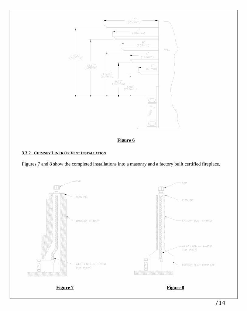
Figure 6
3.3.2 CHIMNEY LINER OR VENT INSTALLATION Figures 7 and 8 show the completed installations into a masonry and a factory built certified fireplace.
Figure 7
Figure 8
/14
The insert must be connected to a listed gas vent liner or B-vent suitable for use with gas. The vent must run within the existing chimney from the outlet collar of the drafthood to the top of the masonry or factory built chimney. Install the vent according to the manufacturer's instructions. Use a maximum of two offsets; (four 45o o elbows), or two 90 elbows. Slope the horizontal pipe at least 1/4" (6.4mm) rise per foot of run. Horizontal runs should not exceed the vertical rise. 3.3.3 Gas Line Installation • Install supply line using any piping approved for your installation meeting CAN/CGA 6.10, AGA 3,
ANSI Z21.24 or Z21.45. A qualified gas fitter should install the gas line in accordance with all local building codes. If codes permit, coiled copper tubing may be used for gas supply.
• Pressure taps are provided on the gas control for test gauge connections to measure the manifold and
inlet pressures. • This appliance must be isolated from the gas supply piping system by closing its individual manual shut
off valve during any pressure testing of the gas supply piping system at test pressures equal to or less than ½” psig (3.45 kPa).
• The appliance and its individual shut off valve must be disconnected from the gas supply piping system
during any pressure testing of the system at test pressures in excess of ½” psig (3.45 kPa). • Install the gas line as follows:
WARNING: Do not use an open flame to test for gas leaks.
The gas line connection on the right side of the insert is shown in Figure 9. An AGA and/or CGA approved shutoff valve can be installed to the flexline if so desired. Installing the shutoff valve between the gas valve and the flex line will allow quick accessibility.
Figure 9
/15
3.3.4 Thermostat, Wall Switch, Or Remote Control Installation The burner control switch is located on the right top side of the faceplate (see Figure 2). For your convenience, the insert can also be operated by a thermostat, a wall switch or a remote control. Millivolt thermostats and remote control kits are available from any authorized Osburn dealer. Bedroom installations
require the use of a wall thermostat.
NOTE: The thermostat or wall switch MUST be rated for millivolt use. Minimize splicing in all millivolt wiring & solder all unavoidable splices.
Remote Control Installation: Please refer to the instructions included with kit. Thermostat or Wall Switch Installation
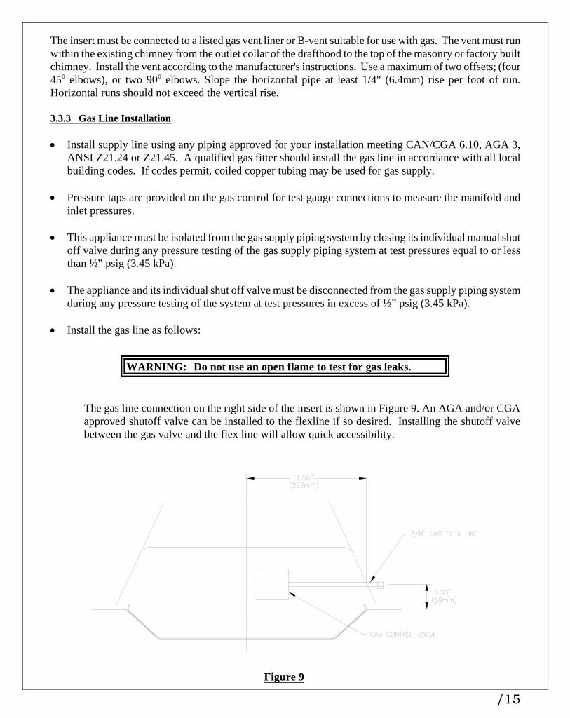
1. Mount the thermostat or wall switch in the desired location and run "two conductor thermostat wire" to the heater's lower right hand corner, close to the gas supply line. Purchase "two conductor thermostat wire," which is not provided, at any local supplier. The gauge of thermostat wire will determine the maximum wire length and distance at which to locate the thermostat or wall switch. See Table 2 and the information packaged with thermostat. Be aware that as the length of wire increases, the probability of adequate operating voltage decreases.
TABLE 2 Thermostat Wire Information
Wire Size Max. Wire Length
AWG mm ft. m
22 0.6 10 3.0
20 0.8 25 7.6
18 1.0 40 12.2
16 1.3 64 19.5
14 1.6 100 30.5
2a. After the insert is installed and the gas line hooked up, solder a female spade connector to each wire
and join them to the male connectors provided on the rear of the burner switch (see Figure 10), or
2b. Solder a fork connector to each wire and install them to the valve.
3. Check tests can be performed on the valve by using the trouble shooting guide, Section 5.0.
4. This switch may be connected in parallel with a thermostat, wall switch, or remote control (see Figure 11).
/16

Figure 10
Figure 11
/17

3.3.5 Vent, Gas Line, & Wiring Connections Unless it is more easily installed with the insert, install the drafthood separately first as follows:
1. Disconnect the drafthood from the insert and fit its collar to the end of the previously installed vent, whether the flue-liner in an existing masonry fireplace or the flue-liner in an existing factory built certified fireplace.
2. Wiring:
i) Cut the plastic pull-tie securing the blue wires.
ii) Cut the plastic pull-tie securing the fan power cord to the heater.
3. Two captive nuts are attached to the air jacket bottom.
i) Remove the two 1/4"-20 screws (2.5" (64mm) long) provided with the faceplate package.
ii) Turn the screws through the two captive nuts to level the unit as required.
4. Push the drafthood upward to 18 1/2" (470mm) above the hearth or fireplace bottom, and start
sliding the insert into the fireplace cavity.
5. Connect the wiring for the thermostat, wall or faceplate switch, or the remote control as noted in #2 of section 3.3.4.
6. The fan power cord is on the left side of the insert and can be routed to the right if desired. Route
the power cord along the bottom outside edge of the heater, not underneath, nor under any sharp edges.
7. Push the insert back until the front firebox flanges are 1/4" (6mm) in front of the masonry or factory
built fireplace facing. As the heater is pushed back, pull the drafthood positioning strips firmly toward the heater front until the drafthood flange is secured under the top clips of the heater (Figure 12).
Figure 12
/18

8. Bend the positioning strips down over the top front edge, cut off the excess strip length, and fold the strips back over the top flange.
9. Connect the union of the gas supply line.
10. Purge the gas line of air.
11. Test the gas line for leaks using an electronic gas leak detector or soapy solution.
WARNING: DO NOT USE AN OPEN FLAME TO TEST FOR GAS LEAKS.
3.3.6 Lower Grille Installation
1. Pull the control panel forward to release it from the retaining clips.
2. Remove the four screws from the firebox supports. NOTE: The Contemporary Bay (KC155) lower grille has two adapter plates attached to the grille assembly.
Remove these plates from the grille assembly and attach them to the firebox supports.
3. Place the lower grille assembly in position against the front of the firebox supports.
4. Secure the lower grille assembly with the four screws that were previously removed (see Figure 13).
Figure 13
5. Push the control panel back into position under the retaining clips.
/19

3.3.7 Faceplate Installation Remove the faceplate panels and the edge trim from the packaging and assemble according to the following instructions: 1. Place the faceplate panels with the finished side down on a flat, soft, non-abrasive surface. 2. Line up the holes of the top and side panels and secure them with six (6) bolts, twelve (12) washers
and six (6) nuts (See Figure 14).
3. Assemble the faceplate trim, joining the mitred corners with corner brackets (See Figure 15).
Figure 14 Figure 15 4. Slide the trim over the edges of the faceplate assembly. 5. Secure the trim to the faceplate with four (4) brass bolts, washers and nuts (See Figure 16). 6. Insert the rocker switch into the rectangular slot of the trim and connect with the two (2) wires from
the fan assembly. This switch will control the fan operation. (See Figure 17a). 7. Place the faceplate assembly around the front of the insert. NOTE: THE ROCKER SWITCH SHOULD BE
ON THE RIGHT HAND SIDE. 8. Align the attachment holes and secure the faceplate to the sides of the unit with the four (4) black
oxide Phillips head sheet metal screws. NOTE: DO NOT ADJUST THE FACEPLATE DEPTH ON THE CORDOVA BAY.
9. Adjust the faceplate mounts to the desired setting (See Figure 17b).
/20
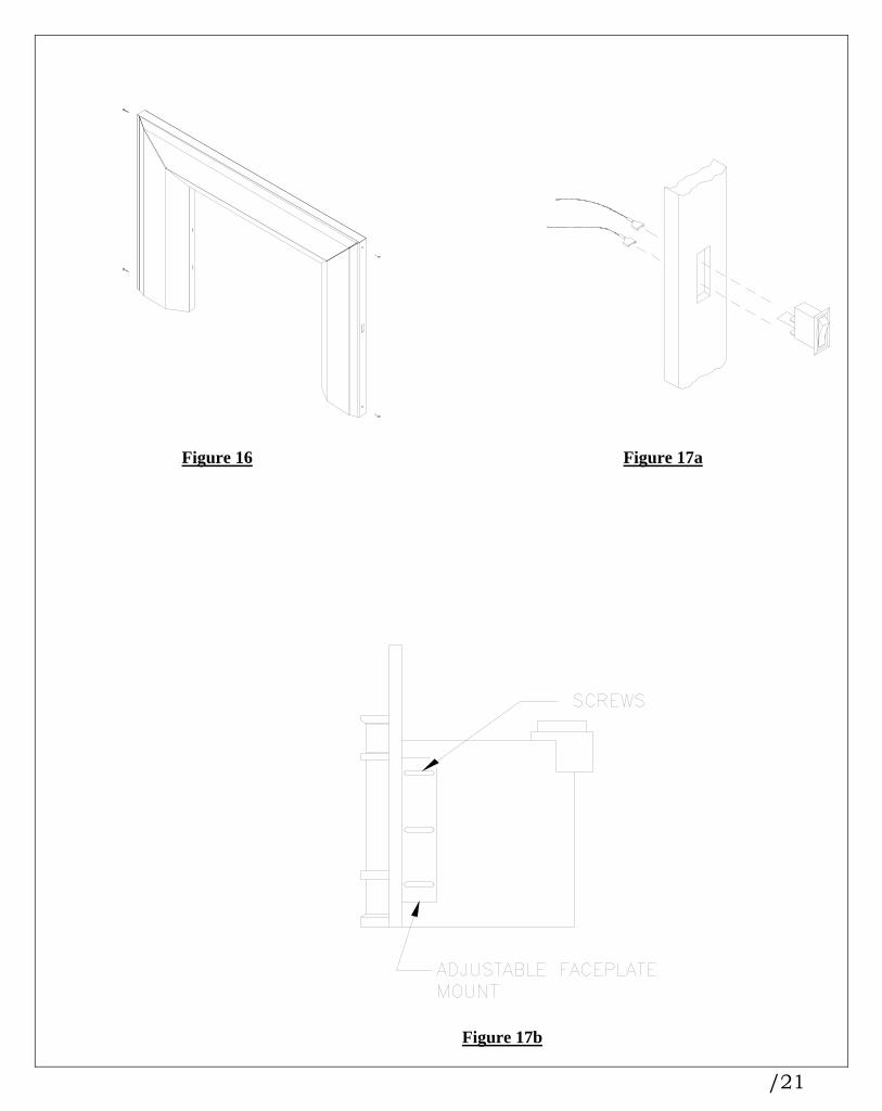
Figure 16 Figure 17a
Figure 17b
/21

3.3.8 Firebox Component Installation 3.3.8.1 Log-Set Installation PROPER PLACEMENT OF THE LOGS IS VERY IMPORTANT. For this reason the Cordova Series comes shipped with the main log (KA1126) pre-installed (see Figures 18 and 19). To complete the log-set arrangement position the front left log (KA1128) onto the two treaded pins located on the front left surface of the burner tray. The underside of the log has two holes which mate to these pins. The top log (KA1127) is similarly located by inserting into the two holes in the underside of this log, the two pins which protrude from the top right rear of the main log. IMPORTANT NOTES: 1. Proper placement of the logs will maximise the aesthetic appearance of the flame. 2. The front left log is properly orientated when the high side of the log is on the left side of the unit. 3. Improper placement of he logs may cause sooting and require pre-mature maintenance.
Figure 18
Figure 19
/22

3.3.8.2 Coal and Ember Placement The Cordova Series has been designed to allow for the application of coals and ember medium. For best results, the coals should not be placed directly over any parts, but instead located near the ports. The fibre medium may then be placed loosely over the ports (see Figure 20). NOTE: THE CENTRE LOG HAS A KNOT-HOLE THROUGH WHICH THE FLAME IS MEANT TO PASS THROUGH. DO NOT place any ember medium over the holes directly underneath this log as it will improperly affect the flame appearance. NOTE: THE FRONT OF THE BURNER HAS BEEN DESIGNED TO ALLOW FOR THE APPLICATION OF EMBER MEDIUM AS WELL AS THE AREA TO THE LEFT OF THE CENTRE LOG AND IN FRONT OF THE REAR LOG. DO NOT PLACE EMBER MEDIUM BETWEEN ANY OTHER LOGS. NOTE: IF THE EMBER MEDIUM BLOCKS THE PORTS, A TRANSLUCENT FLAME MAY RESULT. THIS CAN BE REMEDIED BY LOCALLY REMOVING THE EMBER AWAY FROM THE PORT. WARNING: DO NOT ADD ANY MATERIAL TO THE APPLIANCE WHICH WILL COME IN CONTACT WITH THE FLAMES, OTHER THAN THAT SUPPLIED BY THE MANUFACTURER WITH THE APPLIANCE.
Figure 20
/23

3.3.8.3 Installing The Lower Door Trim WARNING: See sections 4.4 & 4.5 before installing the lower door trim 1. Place the lower door assembly upside down on a soft work area. 2. Remove the four retaining screws from the doorframe bottom. 3. Place the lower door trim in position over the door assembly and align the screw holes. 4. Secure the lower door trim with the four screws that were previously removed (See Figure 21). 5. Re-attach the door assembly onto the firebox.
Figure 21
/24

3.3.8.4 Installing the Door Install the door by assembling its upper hinge slots to the hinge tabs on the top of the firebox. Swing the door down towards the fireplace and latch at the bottom. 3.3.8.5 Installing the Vertical Trims (Contemporary Grille Kits Only) Once the lower door trim has been attached to the door and the door installed, the vertical trims may be attached. Attach one magnet each (two supplied) to the inside surface of the trim pieces. Locate the tongued end of each trim into the slot of the lower trim and rotate towards the unit Next, follow the instructions for attaching the top louvres. When properly installed these will capture the top of the vertical trims behind the upper trim of the louvre stack. NOTE: ALL EDGES ARE TO BE FLUSH WHEN COMPLETE. 3.3.8.6 Installing the Top Grille Assembly 1. Place the top grille assembly above the door. 2. Push the grille retaining plate into the clips and against the stops on top of the insert (see
Figures 22a & b). NOTE: Improper installation of the top grille assembly may cause tarnishing of the brass.
Figure 22a Flush
Figure 22b Bay
/25

3.3.9 Initial Firing When lit for the first few times, the appliance may emit an odour resulting from evaporation of paint and lubricants used in the manufacturing process. Open a door or window for ventilation. Anyone with a respiratory condition may need to leave the room during the initial firings. NOTE: IT IS NORMAL FOR THE APPLIANCE TO EXPAND AND CONTRACT WHILE IT HEATS UP OR COOLS DOWN WHETHER THIS IS FROM A COLD START OR A STEADY-STATE CONDITION WHERE THE FAN HAS COME ON OR OFF. UNDER THESE CIRCUMSTANCES IT IS POSSIBLE THAT THE EXPANSION/CONTRACTION OF THE METAL PARTS MAY PRODUCE A TICKING SOUND. Occasionally, after a cold start, vapour may condense and fog the glass, and the flames may be partially blue. After a few minutes the moisture will disappear and the flames will become yellow. 3.3.9.1 Manifold Pressure Regulator Adjustment The manifold pressure regulator controls gas input and flame height, and is pre-adjusted at the factory. No further adjustment is required. Manifold pressure can be verified only. 3.3.9.2 Pilot Flame Adjustment For proper operation, the pilot and main burner flames must be steady and not lifting off or floating. The top 3/8" - 1/2" (10-13mm) of the thermopile should be engulfed by the pilot flame. The pilot flame adjustment should be performed by a qualified service person only. To adjust the pilot flame, turn the pilot adjustment screw counter-clockwise to increase, and clockwise to decrease the flame. Ensure that the pilot flame completely engulfs the thermopile (see Figure 24).
Figure 24
/26

3.3.9.3 Flue Spillage Test A flue spillage test is recommended as part of this installation and should be performed by a qualified service person only. Hereafter, periodically check the vent draft.
1. Close all the doors and windows in the room.
2. Start all the exhaust fans in the home.
3. Remove the top grille assembly by pulling it forward carefully.
4. Light the heater to the full fire position.
5. After five to ten minutes, insert a match inside a draft duct opening and ensure that the flame wisps and smoke are drawn into the duct at the front corner (see Figures 25a & b).
6. If the flame wisps are not drawn into the ducts, turn the heater off, and determine the cause of the lack of draft. DO NOT OPERATE THE HEATER UNTIL THERE IS SUFFICIENT DRAFT.
7. Replace the top grille assembly after the insert cools.
Figure 25a Figure 25b
3.3.9.4 Altitude Adjustment All valves have been pre-set and certified for installation at elevations from 0 - 4500 feet (1-1372m) above sea level. When installing this heater at higher elevations in Canada, it is necessary to decrease the input rating, by replacing the existing burner orifice with a smaller size for installations over 4500 feet. The appliance’s input should be reduced 4% for each additional 1000 feet above sea level. For the USA, de-rate the heater from sea level according to the gas installation code.
/27

4 .0 Maintenance 4.1 Maintenance Safety Turn off the gas to the main burner and allow the heater to cool for up to 30 minutes before servicing. Service and repair should be done by a qualified service person. The appliance should be inspected before use and at least annually by a professional service technician. More frequent cleaning may be required due to excessive lint from carpeting, bedding material, etc. It is important that the access door compartment, burner, and circulating air passage-ways be kept clean to provide for adequate combustion and ventilation air flow. Do not substitute materials or use components other than factory supplied. 4.2 Recommended Service
1. Examine the venting system periodically.
2. Visually check the burner and pilot flames occasionally. Visually inspect height and colour of flames (see Figure 24).
3. Clean the glass as needed. See section 4.3 for instructions on glass cleaning.
4. Have the appliance inspected annually by a professional service technician.
5. Clean the appliance regularly.
NOTE: SAFETY SCREENS REMOVED FOR SERVICE MUST BE REPLACED PRIOR TO OPERATING THE
HEATER. 4.3 Glass Cleaning The inside of the glass may require periodic cleaning to remove deposits left from impurities in the gas and combustion air. For best results, use a ceramic glass cleaner or polish. A suitable cleaner is available from your dealer. Avoid the use of ammonia based cleaners such as Windex. Do not clean while hot. Do not use abrasive cleaners 4.4 Cleaning of Brass Plated Surfaces Special care must be taken to avoid damage to the high temperature coating applied to each brass piece. DO NOT touch or attempt to clean the brass on your fireplace when the brass surface is warm. Wipe only with a soft damp cotton cloth to maintain original brilliance. CAUTION: Some cleaning agents may contain chemicals that could harm the high temperature coating on the brass. Paper towels and other abrasive materials may scratch the surface. 4.5 Cleaning of Gold Plated Surfaces Take special care and DO NOT use chemical or abrasive cleaners. Wipe only with a soft damp cotton cloth to maintain original brilliance. CAUTION: Vigorous wiping may damage the gold finish.
/28

4.6 Burner & Pilot Cleaning Periodic cleaning is necessary for proper operation.
1. Refer to section 4.7, remove the burner and check that the burner orifice is clean.
2. Visually inspect the pilot. Brush or blow away any dust, lint or foreign debris. If the pilot orifice is plugged, disassembly may be required to remove any foreign material from the orifice or tubing. When the appliance is back in service, check the pilot flame pattern with the Figures in section 3.3.9.2. For relighting, refer to the lighting instructions in section 2.2.
4.7 Fan Replacement & Electrical Schematic
CAUTION: LABEL ALL WIRES PRIOR TO DISCONNECTION WHEN SERVICING CONTROLS. WIRING ERRORS CAN CAUSE IMPROPER AND DANGEROUS OPERATION. VERIFY PROPER OPERATION AFTER SERVICING.
1. Turn off all electrical power to the heater. Unplug fan cord or turn circuit breaker off.
2. Remove the four screws which locate the lower grille assembly, and remove it.
3. Remove the two electrical shield screws and shield (see Figure 26).
4. Remove the two fan bracket to fan base securing screws (see Figure 27).
5. Remove the two fan bracket securing nuts (see Figure 28).
6. Remove the fan wire from the thermal switch.
7. Disconnect the remaining fan wire at the inline connector.
8. Remove the fan by first rotating it 90 degrees backwards, and then sliding it forward and out.
Figure 26 Figure 27
/29

Figure 28
9. Reassemble in reverse order.
10. See Figure 29 for fan electrical schematic.
Figure 29
/30

If necessary, the Fan Thermal Switch may be replaced as follows:
1. Turn off all electrical power to the insert; unplug power cord or turn circuit breaker off.
2. Remove the four screws which locate the lower grille assembly, and remove it.
3. Remove the shield by removing two screws (see Figure 26).
4. Remove the fan thermal switch mount bracket by loosening two screws but do not remove them.
5. Disconnect the two wires from the switch.
6. Remove the two screws securing the switch.
7. Remove and replace the thermal switch.
8. Reassemble in the reverse order. 4.8 Heater Disassembly & Reassembly The following procedure is to be performed by qualified service personnel ONLY. Turn off the gas supply and allow the heater to cool for up to 30 min. 1 Remove the top grille assembly. 2 Remove the door. 3 Remove the lower grille assembly. 4 Remove the logs and coals. 5 Remove the burner tray assembly as a unit by lifting it up and out. 6 Undo the gas flexline connection at the gas valve. These fittings are flared and do not require sealant. 7 Remove the screw securing the pilot assembly to the pilot bracket. 8 Remove the four screws securing the pilot cover plate and gasket & then remove them. 9 Remove the nut securing the orifice to the firebox bottom. 10. Remove the four screws holding the valve bracket to the firebox bottom. 11. Disconnect the thermostat wires from the valve. Once the fasteners are removed, the valve/pilot
assembly can be lowered down and rotated out through the front of the appliance as a complete unit. 12. Reassemble the components in reverse order.
/31
5 .0 Trouble Shooting
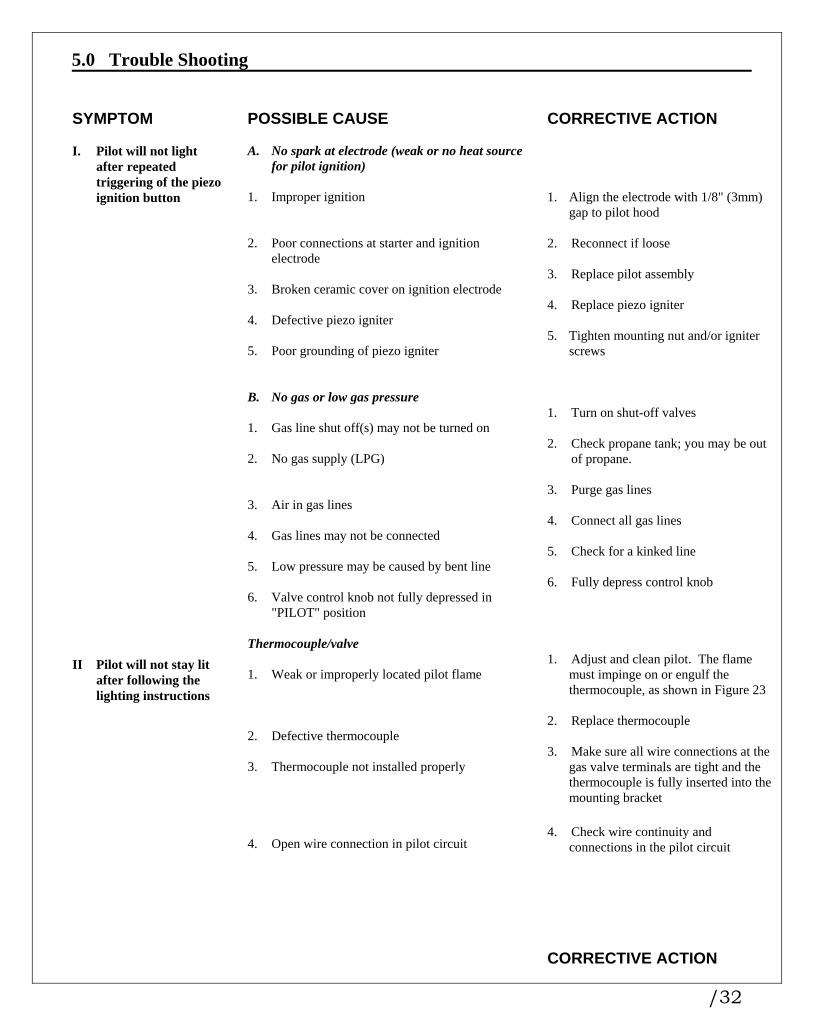
SYMPTOM POSSIBLE CAUSE CORRECTIVE ACTION
A. No spark at electrode (weak or no heat source
for pilot ignition) I. Pilot will not light
after repeated triggering of the piezo ignition button
1. Improper ignition 1. Align the electrode with 1/8" (3mm)
gap to pilot hood 2. Poor connections at starter and ignition
electrode 2. Reconnect if loose
3. Replace pilot assembly 3. Broken ceramic cover on ignition electrode 4. Replace piezo igniter 4. Defective piezo igniter 5. Tighten mounting nut and/or igniter
screws
5. Poor grounding of piezo igniter B. No gas or low gas pressure 1. Turn on shut-off valves 1. Gas line shut off(s) may not be turned on 2. Check propane tank; you may be out
of propane.
2. No gas supply (LPG) 3. Purge gas lines 3. Air in gas lines 4. Connect all gas lines 4. Gas lines may not be connected 5. Check for a kinked line 5. Low pressure may be caused by bent line 6. Fully depress control knob 6. Valve control knob not fully depressed in
"PILOT" position
Thermocouple/valve 1. Adjust and clean pilot. The flame
must impinge on or engulf the thermocouple, as shown in Figure 23
II Pilot will not stay lit after following the lighting instructions
1. Weak or improperly located pilot flame 2. Replace thermocouple 2. Defective thermocouple 3. Make sure all wire connections at the
gas valve terminals are tight and the thermocouple is fully inserted into the mounting bracket
3. Thermocouple not installed properly 4. Check wire continuity and
connections in the pilot circuit 4. Open wire connection in pilot circuit CORRECTIVE ACTION
/32

SYMPTOM POSSIBLE CAUSE Thermocouple/valve (continued) II Pilot will not stay lit
after following the lighting instructions (continued)
5. Connect the millivolt meter probes to the thermopile terminals on the gas valve. Turn the valve to the "PILOT" position, depress and light. If the metre reading is greater than 250 millivolts after 30 seconds, the thermopile is good. If the pilot does not stay lit, the valve is defective. Check section "B" below, before replacing valve
5. Defective valve
B. Defective safety circuit 1. Rewire correctly 1. Improperly wired 2. Check continuity, tighten wiring or
connections and repair 2. Loose or defective connections
3. Check and replace if required 3. Defective electromagnet power unit (EPU) 4. Check continuity & replace if
defective 4. Defective spill switch A. Valve/Switches III. Main burner will not
light 1. Turn to "ON" position 1. Valve control off 2. Check and clean 2. Blockage at the burner (line, orifice, or ports) 3. Conduct a continuity test or jumper
wire test and replace if defective 3. Defective wall switch or thermostat 4. Conduct a test with a jumper wire
and repair as required 4. Defective wiring or connections 5. Reduce wire length to less than 100
feet, or increase wire size 5. Excessive length of thermostat wire from valve
to wall switch or thermostat 6. Wire correctly 6. Wall switch or thermostat incorrectly wired 7. Check batteries and replace if
uired 7. Defective remote control 8. Match frequencies 8. Mismatched remote control frequencies 9. Turn valve and "ON/OFF" switch to
the "ON" position. Check with millivolt meter at terminals TP-TH. Millivolt meter should read greater than 100 millivolts. If the reading is OK and the burner does not come on, replace the gas valve
9. Defective valve CORRECTIVE ACTION
SYMPTOM POSSIBLE CAUSE
/33

10. Recheck using the millivolt meter.
The pilot flame may not be high enough for the flame to properly engulf the thermopile. If so, adjust and reset. If voltage is still insufficient, replace thermopile
III. Main burner will not light (continued)
A. Valve/Switches (continued)
10. Thermopile may not be generating sufficient voltage (325 mV SIT)
11. Follow previous corrective action,
check switch and wiring. Replace where defective
11. Wall switch, thermostat, remote control, or
wires are defective 1. Adjust the log set to avoid direct
flame impingement. Follow log placement instructions
IV. Soot deposits on glass 1. Flame impingement on logs
2. Ensure the air shutter is properly set
NG = .21" (5mm) and LP = fully open
2. Improper venturi setting
3. Ensure that no foreign material
blocks burner flame ports 3. Foreign material impeding burner
4. Clean air inlets 4. Air inlet blocked or restricted 5. Conduct flue spillage test and correct
flue as required 5. Vent system is restricted or inadequate
1. Ensure that no foreign material
blocks air inlets and that the burner shutter is correctly adjusted. Ensure the vent is adequate
1. Insufficient combustion air being supplied V. Flame burns blue and
lifts off burner
2. Check manifold pressure 2. Manifold pressure set too high 3. Check vent system 3. Vent system restricted See V VI. Frequent pilot outage
problem 1. Correct flue as required 1. Vent system is restricted or inadequate VII. Flames impinge on
firebox top 2. Check manifold pressure as required 2. Manifold pressure too high
/34

6 .0 Replacement Parts When requesting service or replacement parts for your insert, please provide model name, fuel type, and serial number. All parts listed below may be ordered from an authorized dealer. Cordova Series Replacement Parts List CB25 and CF25
COMMON PARTS
COMMON PARTS PART No. DESCRIPTION PART No. DESCRIPTION KA108 Blower Assembly North America HM22 Grille Springs (2/unit) KA155 Burner Assembly North America KA1126 Main Log
CZ0097 Burner Orifice Jam Nut KA1127 Top Log (with knot-hole) KA1062 Burner Orifice LP KA1128 Front Left Log (Twig) KA1030 Burner Orifice NG BN0022 On/Off Wires (2/unit)
HE23 Burner Switch On/Off HG58 Piezo Ignitor CZ037 Coals HG71 Pilot Assembly LP With Ignitor
KA1020 Door Gasket HG70 Pilot Assembly NG With Ignitor HG60 Extension Knob, On/Off HG51 Pilot Orifice LP HG61 Extension Knob, High/Low HG52 Pilot Orifice NG AF125 Faceplate Blk, Beveled, 28”x41” HG37 Thermocouple
HE57 Fan Thermal Switch HE32 Thermodisc Spill Switch KA172 Valve Assembly Cordova LP
BC044 Kit Glowing Ember BV KA173 Valve Assembly Cordova NG
/35

Cordova Bay Victorian Assembly Parts
Cordova Flush
Victorian Assembly Parts PART No. DESCRIPTION PART No. DESCRIPTION
KB106 Access Door Assembly KA133 Access Door Assembly
KB112 Door Assembly KA141 Door Assembly KB1026 Door Trim Lower Brass KA1039 Door Trim Lower Brass
KB1023 Door Trim Upper Brass KA1038 Door Trim Upper Brass KB1024 Gasket Glass Tadpole KA1037 Gasket Glass Tadpole KB1007 Glass Front KA1036 Glass
KB1008 Glass Sides (2/unit) KA144 Grille Assembly Top KB116 Grille Assembly Top KA1047 Louvre Brass Top KB1010 Louvre Brass Top
Cordova Bay Contemporary Style Parts
Cordova Flush
Contemporary Style Parts PART No. DESCRIPTION PART No. DESCRIPTION
KC123 Access Door Assembly KD171 Access Door Assembly KB112 Door Assembly KA141 Door Assembly KC112 Door Trim Lower Gold KD1014 Door Trim Lower Gold KC114 Door Trim Upper Gold KD1013 Door Trim Upper Gold
KB1024 Gasket Glass Tadpole KA1037 Gasket Glass Tadpole KB1007 Glass Front KA1036 Glass KB1008 Glass Sides (2/unit) KD172 Grille Assembly Top
KC124 Grille Assembly Top KD1005 Louvre Gold Top KC1024 Vertical Trim (Gold) with Magnet KD1022 Vertical Trim (Gold) with Magnet
Left or Right Left or Right KC1012 Louvre Gold Top
/36

1700, rue Léon-Harmel, Québec (Québec) G1N 4R9 tel. : (418) 527-3060 fax : (418) 527-4311
e-mail : [email protected] web site : www.osburn-mfg.com
LIMITED WARRANTY The warranty of the manufacturer extends only to the original consumer purchaser and is not transferable. This warranty covers brand new products only, which have not been altered, modified nor repaired since shipment from factory. Proof of purchase (dated bill of sale), model name and serial number must be supplied when making any warranty claim to your Osburn dealer. This warranty applies to normal residential use only. Damages caused by misuse, abuse, improper installation, lack of maintenance, over firing, negligence or accident during transportation are not covered by this warranty. This warranty does not cover any scratch, corrosion or discoloration caused by over firing, abrasives or chemical cleaners. Any defect or damage caused by the use of unauthorized parts or others than original parts void this warranty.
An authorized qualified technician must perform the installation in accordance with the Instructions supplied with this product and all local and national building codes. Any service call related to an improper installation is not covered by this warranty.
Returned products are to be shipped prepaid to the manufacturer for investigation. If a product is found to be defective, the manufacturer will repair or replace such defect and reasonable transportation fees will be refunded. Repair work covered by the warranty, executed at the purchaser domicile by an authorized qualified technician requires the prior approval of the manufacturer. Labour cost and repair work to the account of the manufacturer are based on predetermined rate schedule and must not exceed the wholesale price of the replacement part.
The manufacturer at its discretion may decide to repair or replace any part or unit after inspection and investigation of the defect. The manufacturer may, at its discretion, fully discharge all obligations with respect to this warranty by refunding the wholesale price of any warranted but defective parts
The manufacturer shall in no event be responsible for any special, indirect, consequential damages of any nature, which are in excess of the original purchase price of the product.
WARRANTY APPLICATION DESCRIPTION
PARTS LABOUR
Combustion chamber (weldings only) 5 years 5 years
Stainless baffle 5 years 1 year
Carbon Steel baffle 2 years 1 year
Gas Valve, piezo, thermopile, thermoswitch, burner 1 year 1 year
Logs N/A N/A
Ceramic glass (thermal breakage only) 5 years N/A
Paint, gasket, blower, Blower thermoswitch and rheostat N/A 1 year
Gold plating (tarnishing) 5 years N/A
Shall your unit or a components be defective, contact immediately your Osburn dealer. Prior to your call make sure you have the following information necessary to your warranty claim treatment:
• Your name, address and telephone number; • Serial number and model name as indicated on the nameplate fixed to the back of your unit;• Bill of sale, dealer’s name;
• Nature of the defect and any relevant information.
Before shipping your unit or defective component to our plant, you must obtain from your Osburn dealer an Authorization Number. Any merchandise shipped to our plant without authorization will automatically be refused and returned to sender.
/37