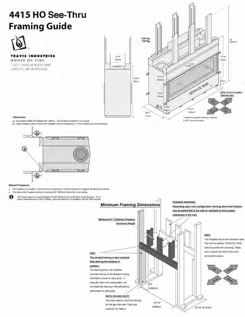
Gas Fireplace Framing Guide · Gas Fireplace Framing Guide Models, 21 TRV, 564 SS, 564 SS CF, 564...
18
Gas Fireplace Framing Guide Models, 21 TRV, 564 SS, 564 SS CF, 564 HO, 864 TRV, 864 TRV CF, 854 ST, 864 HO, 3615 HO, 4415 HO, 4415 HO See-Thru, 6015 HO, 4237 Clean Face and ProBuilder 42 Note: For General Reference Only. Aways consult the product Installation Manual for exact installation information. Installation Manuals can be found at www.fireplacex.com 1/18/2018
Transcript of Gas Fireplace Framing Guide · Gas Fireplace Framing Guide Models, 21 TRV, 564 SS, 564 SS CF, 564...

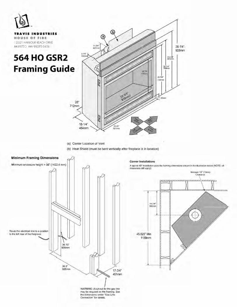
Gas Fireplace Framing Guide
Models, 21 TRV, 564 SS, 564 SS CF, 564 HO, 864 TRV, 864 TRV CF, 854 ST, 864 HO,
3615 HO, 4415 HO, 4415 HO See-Thru, 6015 HO, 4237 Clean Face and ProBuilder 42
Note: For General Reference Only. Aways consult the product Installation Manual for
exact installation information.
Installation Manuals can be found at www.fireplacex.com
1/18/2018


CAUTION: RESTRICTOR ADJUSTMENT REQUIREDThis heater will not operate properly if the vent restrictor is not set for your specific installation. See “Vent configuration” section in the owner’s installation manual.
FIRST FIRE OR START UPYour appliance has been finished with the highest quality paint. Though this paint dries quickly to the touch, it does not cure or become hard until heated up by the appliance during first fire. For this reason the stove will emit light smoke and have a slight odor. Consult your owner’s manual for the complete paint curing instruc-tions. Partially open doors or windows to minimize smoke & odor.
LA PRECAUCIÓN: EL AJUSTE DE RESTRICTOR REQUERIDOEste calentador no funcionará apropiadamente si el restrictor de abertura no está previsto para su instalación específica. See "La configuración de abertura" corte transversal en el manual de instalación del propietario.
EL PRIMERO FUEGO O COMIENZA PARA ARRIBASSu aparato ha estado terminado con la pintura de mejor calidad. Aunque esta pintura se seca rápidamente al tacto, no hace la cura o becomve duro until cali-enta por el aparato durante el primer fuego. Para esta razón la cocina emitirá humo ligero y tendrá un olor leve. Consulte el manual de su propietario para la pintura completa curar las instrucciones. Abra puertas o ventanas parcialmente para minimizar humo & olor.
WARNING:Sheet metal edges can be sharp
ADVERTENCIA:Los bordes de chapa metálica pueden estar afilados
112-10001


564 SS GSR2 SCR Top Vent Configuration
8" (203mm) Diameter Vent
Framing
Guide
TRAVIS INDUSTRIES
HOUSE OF FIRE
12521 HARBOUR REACH DRIVE
MUKILTEO, WA 98275-5458
28-1/2"* 724mm
<16-3/4" 426mm�
* Includes the required 1/2" (13mm)
clearance.
Minimum Framing Dimensions - Rear Vent Configuration
HINT: place the fireplace so the center
line is at least 5" (127mm) from both
vertical framing members at the rear (this
allows the vent to pass through the
framing without modfications)
Minimum 38" (965mm)
Fireplace Enclosure Height
Route the
electrical line to
a position to the
left rear of the
fireplace.
/.�
33-1/2"
851mm
36-1/2"
Included Firestop (required)
Part# 250-00747
Vent Clearances for B" (203mm) dia. Vent:
1" (25mm) to the sides, 1" (25mm) below,
and 4" (102mm) above the vent to
combustibles
.-·ki··Center of Rear Vent
'J / 24-1/4"
616mm
845mm
Weight: 155 Lbs. (70.4kg)
Minimum Framing Dimensions - Top Vent Configuration
Route the electrical line to
a position to the left rear
of the fireplace.
33-1/2'
,.<'"�
851mm
36-1/2"
927mm
Minimum enclosure height= 38' [=
,,,,� 438mm
y�
927mm The on/off switch/thermostat wire (if
used) should be routed to a location
near the right front of the fireplace.
WARNING: A cut-out for the gas line
may be required on the framing. See
the dimensions under "Gas Line
Connection" for details.
Corner Installations - Rear Vent Configuration A typical 45° installation uses the framing dimensions shown in the illustration below (NOTE: all clearances still apply).
7"(178mm) Approximate
(varies due to vent installation) __
6" (152mm) Section for 2x6
(51mm X 152mm) Walls
4" (102mm) Section for 2x4
(51mm X 102mm) Walls
45-3/4"
Minimum 1" (25mm) Clearance
564 SS Firestop
Corner Installations - Top Vent Configuration A typical 45" installation uses the framing dimensions shown in the illustration below (NOTE: all clearances still apply)
45-3/4"
Minimum 1/2" (13mm) Clearance
The on/off switch/thermostat wire (if
used) should be routed to a location
near the right front of the fireplace.


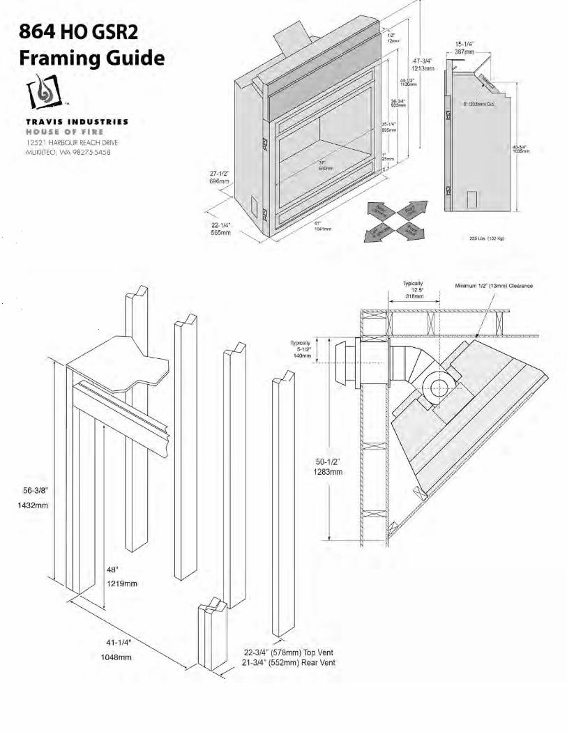
864TRVGSR2
Framing Guide
TRAVIS INDUSTRIES
HOUSE OF FIRE
12521 HARBOUR REACH DRIVE
MUKILTEO, WA 98275-5458 20-5/8'"
Top Vent Configuration 8" (203mm) 0 Vent
Minimum Framing Dimensions - Top Vent Configuration
Route the electrical line to a position to the left rear of the fireplace.
38-1/2"
978mm
41-1/4"
1048mm
Minimum enclosure height= 38-1/2" (978mm)
_.,/-20-3/4"
-� The on/off switch/thermostat wire (if used) should be routed to a location near the right front of the fireplace.
Corner Installations - Top Vent Configuration
A typical 45° installation uses the framing dimensions shown in the illustration below (NOTE: all clearances still apply).
50-1/2"
15-1/2" 394mm
Minimum 112' (13mm) Clearance
---@
Optional "Extra Room
38-1/4
972mm
Weight: 205 Lbs. (93 Kg)
Rear Vent Configuration 8" (203mm) 0 Vent
30·314" 781mm
Minimum Framing Dimensions - Rear Vent Configuration
HINT: place the fireplace so the center
line is at least 5" (127mm) from both vertical framing members at the rear (this
allows the vent to pass through the framing without modfications)
Route the electrical line to
a position to the left rear of the
fireplace.
38-1/2"
��978mm
41-1/4" 1048mm
Minimum enclosure height= 38-1/2" (978mm)
Included Firestop (required)
Part # 93006094
25-3/4"
Vent Clearances 8" (203mm) dia. Vent:
1" (25mm) to the sides, 1" (25mm) below, and 3" (76mm) above the vent to
combustibles . -··Ir _Center of Rear Vent
::r
38"
965mm
30-3/4"
781mm
-.. �ff ,e;;;
� The on/off switchtthermostat wire (if used) should be routed to a location
near the right front of the fireplace.
Corner Installations - Rear Vent Configuration
A typical 45° installation uses the framing dimensions shown in the illustration below (NOTE: all clearances still apply).
NOTE
7·112'(91mm) Approximate
{varies due to vent installation)
Most installations use:
6'(152mm)Sectiontor
2X 6Walls(51mm X 152mm)
4"(102mm)Sectionlor
2x4 Walls (21mm X 102mm)
(Travis 1198900166)
50-1/2"
TravisFirestop
Minimum 1" {25mm) Clearance (sku 93006094)