Gas-fired water boiler - Weil-McLain · Control Addendum Part No. 550-100-040/0804 Gas-fired water...
28
Control Addendum Part No. 550-100-040/0804 Gas-fired water boiler Ultra Interface Kit Revise module parameters ONLY if you fully understand the purpose and result of the changes. Tampering with control settings can result in unreliable operation, with possible severe personal injury, death or substantial property damage. This document must only be used by a qualified heating installer/service technician. Read all instructions, including this Addendum, the Ultra Boiler Control Supplement and the Boiler Manual before installing. Perform steps in the order given. Failure to comply could result in severe personal injury, death or substantial property damage. Installation must comply with local requirements and with the National Fuel Gas Code, ANSI Z223.1 for U.S. installations or CSA B149.1 or B149.2 for Canadian installations. Contents Overview ........................................................................... 3 How to set parameters ...................................................... 4 Table 1 — Default parameter settings ............................... 5 Installing Gascom software ............................................... 6 Setting parameters using Gascom software ...................... 7 Monitoring the MCBA ................................................... 11 Notes ............................................................................... 12 Parameter explanations ................................................... 13 Outdoor reset operation ........................................... 14 Automatic temperature boost ................................... 16 Fan speed settings ...................................................... 17 Differential (hysteresis) settings ................................ 18 Parameter reference table ......................................... 19 – 27 Record of parameter changes .......................................... 28
Transcript of Gas-fired water boiler - Weil-McLain · Control Addendum Part No. 550-100-040/0804 Gas-fired water...

Control Addendum
Part No. 550-100-040/0804
Gas-firedwater boiler
Ultra Interface KitRevise module parameters ONLY if you fully understand thepurpose and result of the changes. Tampering with controlsettings can result in unreliable operation, with possible severepersonal injury, death or substantial property damage.
This document must only be used by a qualified heatinginstaller/service technician. Read all instructions, including thisAddendum, the Ultra Boiler Control Supplement and the BoilerManual before installing. Perform steps in the order given.Failure to comply could result in severe personal injury, deathor substantial property damage.
Installation must comply with local requirements and with theNational Fuel Gas Code, ANSI Z223.1 for U.S. installations orCSA B149.1 or B149.2 for Canadian installations.
ContentsOverview ...........................................................................3
How to set parameters ......................................................4
Table 1 — Default parameter settings ...............................5
Installing Gascom software ...............................................6
Setting parameters using Gascom software ......................7
Monitoring the MCBA ................................................... 11
Notes ............................................................................... 12
Parameter explanations ................................................... 13
Outdoor reset operation ........................................... 14
Automatic temperature boost ................................... 16
Fan speed settings ...................................................... 17
Differential (hysteresis) settings ................................ 18
Parameter reference table......................................... 19 – 27
Record of parameter changes.......................................... 28

Part number 550-100-040/08042
GAS-FIRED WATER BOILER — CONTROL ADDENDUM — Ultra Interface Kit
Hazard definitionsThe following defined terms are used throughout this manual to bringattention to the presence of hazards of various risk levels or to importantinformation concerning the life of the product.
Indicates presence of hazards that will cause severe personalinjury, death or substantial property damage.
Indicates presence of hazards that can cause severe personalinjury, death or substantial property damage.
Indicates presence of hazards that will or can cause minorpersonal injury or property damage.
Indicates special instructions on installation, operation ormaintenance that are important but not related to personalinjury or property damage.
General
Part number 550-100-040/0804 3
GAS-FIRED WATER BOILER — CONTROL ADDENDUM — Ultra Interface Kit
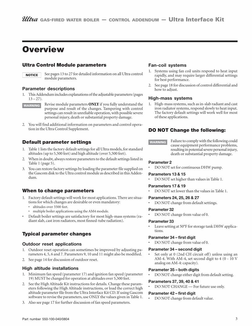
Ultra Control Module parameters
See pages 13 to 27 for detailed information on all Ultra controlmodule parameters.
Parameter descriptions1. This Addendum includes explanations of the adjustable parameters (pages
13 – 27).Revise module parameters ONLY if you fully understand thepurpose and result of the changes. Tampering with controlsettings can result in unreliable operation, with possible severepersonal injury, death or substantial property damage.
2. You will find additional information on parameters and control opera-tion in the Ultra Control Supplement.
Default parameter settings1. Table 1 lists the factory default settings for all Ultra models, for standard
altitudes (up to 5,500 feet) and high altitude (over 5,500 feet).
2. When in doubt, always restore parameters to the default settings listed inTable 1 (page 5).
3. You can restore factory settings by loading the parameter file supplied onthe Gascom disk to the Ultra control module as described in this Adden-dum.
When to change parameters1. Factory default settings will work for most applications. There are situa-
tions for which changes are desirable or even mandatory:• altitudes over 5500 feet.• multiple boiler applications using the AM4 module.
• Default boiler settings are satisfactory for most high-mass systems (ra-diant slab, cast iron radiators, most finned-tube radiation).
Typical parameter changes
Outdoor reset applications1. Outdoor reset operation can sometimes be improved by adjusting pa-
rameters 4, 5, 6 and 7. Parameters 9, 10 and 11 might also be modified.
2. See page 14 for discussion of outdoor reset.
High altitude installations1. Minimum fan speed (parameter 17) and ignition fan speed (parameter
19) MUST be changed for operation at altitudes over 5,500 feet.
2. See the High Altitude Kit instructions for details. Change these param-eters following the High Altitude instructions, or load the correct highaltitude parameter file from the Ultra Interface Kit CD. If using Gascomsoftware to revise the parameters, use ONLY the values given in Table 1.
3. Also see page 17 for further discussion of fan speed parameters.
Overview
Fan-coil systems1. Systems using fan coil units respond to heat input
rapidly, and may require larger differential settingsfor best performance.
2. See page 18 for discussion of control differential andhow to adjust.
High-mass systems1. High-mass systems, such as in-slab radiant and cast
iron radiator systems, respond slowly to heat input.The factory default settings will work well for mostof these applications.
DO NOT Change the following:
Failure to comply with the following couldcause equipment performance problems,resulting in potential severe personal injury,death or substantial property damage.
Parameter 2• DO NOT set for continuous DHW pump.
Parameters 13 & 15• DO NOT set higher than values in Table 1.
Parameters 17 & 19• DO NOT set lower than the values in Table 1.
Parameters 24, 25, 26 & 27• DO NOT change from default settings.
Parameter 32• DO NOT change from value of 0.
Parameter 33• Leave setting at 50°F for storage tank DHW applica-
tions.
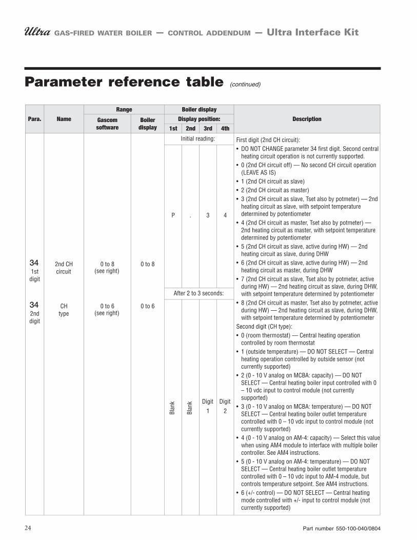
Parameter 34 – first digit• DO NOT change from value of 0.
Parameter 34 – second digit• Set only at 0 (2nd CH circuit off) unless using an
AM-4. With AM-4, set second digit to 4 (0 - 10 Vanalog on AM-4: capacity).
Parameter 35 – both digits• DO NOT change either digit from default setting.
Parameters 37, 39, 40 & 41• DO NOT CHANGE — For future use only.
Parameter 42 – first digit• DO NOT change from default value.
Part number 550-100-040/08044
GAS-FIRED WATER BOILER — CONTROL ADDENDUM — Ultra Interface Kit
METHOD 2 — Ultra Interface Kit
Using the Ultra Interface Kit and a Windows 95+ basedcomputer with an available serial port.
Contents of Ultra Interface Kit1. GCI communication module with cables (Allows
connection of a PC to the Ultra Control Module).
2. Gascom software (Provides Microsoft Windows userinterface with Ultra Control Module).
Computer requirements1. PC computer with available serial port.
2. CD-ROM drive (to load software onto computer).
3. Microsoft Windows, version 95 or later.
Purposes of the Interface Kit1. Modify control parameters when necessary — Com-
puter interface simplifies parameter change.
2. Monitor control operation — All boiler inputs canbe viewed on-screen in both text mode and in real-time graphical display.
3. Troubleshoot boiler — Use Gascom software todownload a log of error codes recorded by the UltraControl Module.
Using Gascom software1. See procedures in this addendum.
Using parameter files1. The Gascom software disk contains parameter files
for high altitude, AM4 applications, fan-coil systemsand default boiler parameters.
2. See “Setting Parameters Using Gascom Software” forfile listings and procedures.
METHOD 3 — GMKEY device1. (Not covered in this supplement) Using a GMKEY
device that will flash a new set of parameters to thecontrol. This method is currently reserved for Weil-McLain representatives. Only the first two methodsof changing parameters are discussed in this docu-ment.
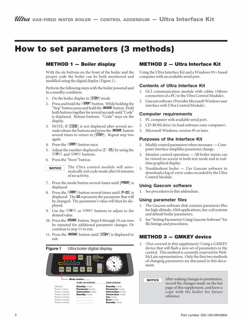
How to set parameters (3 methods)
METHOD 1 — Boiler display
With the six buttons on the front of the boiler and theproper code the boiler can be both monitored andmodified using the digital display (Figure 1).
Perform the following steps with the boiler powered andin a standby condition.
1. On the boiler display in [STBY] mode
2. Press and hold the button. While holding the"Step" button press and hold the button. Holdboth buttons together for several seconds until "Code"is displayed. Release buttons. “Code” stays on thedisplay.
3. NOTE: If [CODE] is not displayed after several sec-onds release the buttons and press the buttonseveral times to return to [STBY]. Repeat step twoagain.
4. Press the button once.
5. Adjust the number displayed to [C - 05] by using the and buttons.
6. Press the "Store" button.
The Ultra control module will auto-matically exit code mode after10 minutesof no activity.
7. Press the mode button several times until [PARA] isdisplayed.
8. Press the button several times until [P-XX] isdisplayed. The XX represents the parameter that willbe changed. The parameter’s value will then be dis-played.
9. Use the or buttons to adjust to thedesired value.
10. Press the button. Steps 8 through 10 can nowbe repeated for additional parameter changes. Orcontinue to step 11 to exit.
11. Press the button until [STBY] is displayed toexit.
Figure 1 Ultra boiler digital display
After making changes to parameters,record the changes made on the lastpage of this supplement, and leave acopy with the boiler for futurereference.
Part number 550-100-040/0804 5
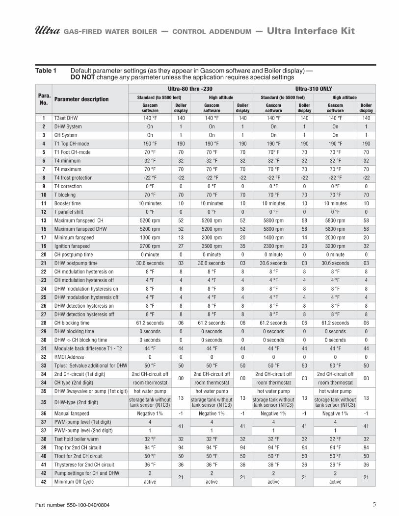
GAS-FIRED WATER BOILER — CONTROL ADDENDUM — Ultra Interface Kit
Table 1 Default parameter settings (as they appear in Gascom software and Boiler display) —DO NOT change any parameter unless the application requires special settings

Part number 550-100-040/08046
GAS-FIRED WATER BOILER — CONTROL ADDENDUM — Ultra Interface Kit
Installing Gascom software on your computer
1. In order to run the Gascom it must be installed fromthe supplied software CD. Insert the CD into theCD-Rom drive and open it through “My Computer.”Copy the “Gascom” file folder over to a directory onyour computer’s hard drive. (Write down where youput this folder for future configuration.)
2. Once you have copied the folder, navigate to it onyour hard drive using “My Computer” or “WindowsExplorer”. Locate the file named “gascom.exe”. Cre-ate a shortcut on the desktop to this file by clickingon it and holding the right mouse button and drag-ging it to the desktop. Release the mouse button andchoose “Create Shortcut(s) here”. This shortcut willnow be used to open the Gascom program.
3. Close all windows and use the newly created short-cut to open the Gascom program. Once Gascom isopen for the first time you must configure it to workproperly on your computer and with the Ultra boiler.
4. Choose “Gascom” from the menu bar and then “con-figuration.” A dialog box will open as shown below.
5. From the first dropdown box choose “StandardHR7A60Hz” for the MCBA1400 type. Choose from
the second dropdown box “GCI232” for the Inter-face device. The choice for the Communication portdepends on the computer being used. Choose theavailable serial port that you will connect the GCIInterface module to. If you do not know the name ofthe serial port that you will be using you can oftenfind it using trial and error. The “Gascom directory”is the location on your computer where the Gascomprogram is stored. In the example below the “Gascom”folder is stored on the C: drive. If you do not knowthe location of the folder you may find it by rightclicking on the shortcut that was created on the desk-top and then choosing “Properties”. There is often a“Target” or “Start in” listing that shows the locationof the file folder.
6. The last entry in the configuration menu is the “Ac-cess code” field. Entering the correct code in the loca-tion will allow access to Parameter Numbers 1 to 42.An access code is not needed in order to access pa-rameters 1 to 4, monitor boiler performance, or viewthe logged error codes. THE ACCESS CODE WILLCLEAR AFTER THE PROGRAM CLOSES.

Part number 550-100-040/0804 7
GAS-FIRED WATER BOILER — CONTROL ADDENDUM — Ultra Interface Kit
Setting parameters using Gascom software
Using Gascom software1. Connect the GCI interface module from the com-
munications kit to the serial port on the computer.Connect the ribbon cable to the Ultra Controlthrough the connection on the front display panel.(Series 1 boilers have the connection under the topfront cover on the control itself.) Plug in the GCIpower cord.
2. Make sure the power to the boiler is on.
3. Start the Gascom program and go through configu-ration if it has not already been completed. If theconfiguration was done previously choose “Readfrom MCBA,” as shown below.
4. If the device is connected correctly and the correctcommunication port is chosen the following screenwill appear. This indicates that communication hasbeen established between the Ultra’s MCBA controland the computer.
5. The first four parameters are the only parametersavailable to change unless an Access code is enteredunder the configuration menu.
Entering the access code makes allparameters 1 through 42 available forchange. Do not change any parameter thatis not directly addressed in this Addendumas an acceptable change. Some parametersin the control should never be changedunder any circumstance, as explained inthis Addendum. After making changes toparameters, record the changes made onthe last page of this supplement, and leavea copy with the boiler for future reference.
Accessing parameters 5–421. If access to parameters 5-42 is needed, choose the
“configuration” option from the “gascom” menu.
2. To access parameters 5–42, enter “05” in the accesscode box, as shown below. Choose “OK”.
8. Parameters 1 through 42 should all be visible.
Part number 550-100-040/08048
GAS-FIRED WATER BOILER — CONTROL ADDENDUM — Ultra Interface Kit
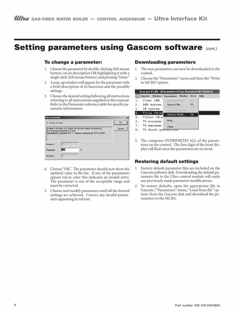
To change a parameter:1. Choose the parameter by double-clicking (left mouse
button) on its description OR highlighting it with asingle click (left mouse button) and pressing “Enter.”
2. A pop-up window will appear for the parameter witha brief description of its functions and the possiblesettings.
3. Choose the desired setting following all instructionsreferring to all instructions supplied in this manual.Refer to the Parameter reference table for specific pa-rameter information.
4. Choose “OK”. The parameter should now show theupdated value in the list. If any of the parametersappear red in color this indicates an invalid entry.The parameter is out of the acceptable range andmust be corrected.
5. Choose and modify parameters until all the desiredsettings are achieved. Correct any invalid param-eters appearing in red text.
Setting parameters using Gascom software (cont.)
Downloading parameters1. The new parameters can now be downloaded to the
control.
2. Choose the “Parameters” menu and then the “Writeto MCBA” option.
3. The computer OVERWRITES ALL of the param-eters on the control. The first digit of the front dis-play will flash once the parameters are received.
Restoring default settings1. Factory default parameter files are included on the
Gascom software disk. Downloading the default pa-rameter file to the Ultra control module will undoany previously made parameter modifications.
2. To restore defaults, open the appropriate file inGascom (“Parameters” menu, “Load from file” op-tion) from the Gascom disk and download the pa-rameters to the MCBA.

Part number 550-100-040/0804 9
GAS-FIRED WATER BOILER — CONTROL ADDENDUM — Ultra Interface Kit
Setting parameters using Gascom software (cont.)
Loading parameters from a file1. The files listed in Tables 2 and 3 (next page) are lo-
cated on the Gascom software disk.
2. To load the appropriate parameter file, use the “Pa-rameters” menu, “Load from file” option.
3. Navigate to the file and select it to load the param-eters.
You must be careful to select the correct filefor the boiler model being used. Installinga parameter file for the wrong model couldresult in overfiring the boiler, resulting inpossible severe personal injury, death orsubstantial property damage.
Table 2 Gascom software disk parameter files for Ultra-80 through Ultra-230 (Standard files workbest for radiant slab, suspended-floor radiant, finned-tube baseboard and cast iron radiatorsytems; Fan-coil files work best for fan-coil systems.) The factory default file is the filenamed, “80-230.par.”

Part number 550-100-040/080410
GAS-FIRED WATER BOILER — CONTROL ADDENDUM — Ultra Interface Kit
Setting parameters using Gascom software (cont.)
Loading parameters from a file1. The files listed in Tables 2 (previous page) and 3 (be-
low) are located on the Gascom software disk.
2. To load the appropriate parameter file, use the “Pa-rameters” menu, “Load from file” option.
3. Navigate to the file and select it to load the param-eters.
You must be careful to select the correct filefor the boiler model being used. Installinga parameter file for the wrong model couldresult in overfiring the boiler, resulting inpossible severe personal injury, death orsubstantial property damage.
Table 3 Gascom software disk parameter files for Ultra-310 ONLY (Standard files work best forradiant slab, suspended-floor radiant, finned-tube baseboard and cast iron radiator sytems;Fan-coil files work best for fan-coil systems.) The factory default file is the file named,“310.par.”

Part number 550-100-040/0804 11
GAS-FIRED WATER BOILER — CONTROL ADDENDUM — Ultra Interface Kit
Monitoring the MCBA and reading error logs
Monitoring the Ultra control1. When ready to monitor the control, select “Monitor
MCBA” from the “Monitor” menu.
2. To change the setup for monitoring, select “Configu-ration” from the “Monitor” menu.
3. You will see the dialog box like the one below.
4. Scroll down the list and select the parameters youwant to monitor.
5. The check mark boxes indicate which parameters willbe shown on the monitor display. The first check boxmeans a line will show for the parameter. The secondcheck box means the paramerter will be shown in thelegend. Check boxes are enabled or disabled by click-ing on “Edit.”
6. Click on “Edit” to add or change check boxes forparameters.
• You can change the line end style, make it solid ordashed, and change the way corners appear.
• You can also change line color.
• Enable the parameter to show on the display byclicking to cause a check next to “Line.” To preventthe parameter from showing on the monitor, re-move the check mark.
• Enable the parameter to be listed in the legend byclicking to cause a check next to “Legend.” To pre-vent the parameter from showing in the legend,remove the check mark.
• Click “OK” to accept the changes and return.
7. Adjust monitor background, scale, legend and fontsize in the dialog box below.
8. When all changes are made, click “OK” to set theconfiguration.
9. Select “Save to file” to save the configuration to disk.Select “Load from file” to use an existing configura-tion.
10. From the “Monitor” menu, you can also:
• Save a configuration file to disk.
• Print the configuration.
Reviewing error logs1. Use the “Error” menu in Gascom to load the error
log from the control module (MCBA) or from a fileyou have saved.
2. From the “Error” menu, you can also:
• Save an error log to disk.
• Print an error log.
• Clear the control module error log.
Part number 550-100-040/080412
GAS-FIRED WATER BOILER — CONTROL ADDENDUM — Ultra Interface Kit
Notes

Part number 550-100-040/0804 13
GAS-FIRED WATER BOILER — CONTROL ADDENDUM — Ultra Interface Kit
Revise module parameters ONLY if you fully understand the purpose and result ofthe changes. Tampering with control settings can result in unreliable operation,with possible severe personal injury, death or substantial property damage.
This document must only be used by a qualified heating installer/service technician.Read all instructions, including this Addendum, the Ultra Boiler Control Supplementand the Boiler Manual before installing. Perform steps in the order given. Failure tocomply could result in severe personal injury, death or substantial property damage.
Installation must comply with local requirements and with the National Fuel GasCode, ANSI Z223.1 for U.S. installations or CSA B149.1 or B149.2 for Canadianinstallations.
Parameter explanations

Part number 550-100-040/080414
GAS-FIRED WATER BOILER — CONTROL ADDENDUM — Ultra Interface Kit
Outdoor reset operation1. Outdoor reset adjusts the supply water temperature so
the heat output from the heating units matches the heatloss as the outdoor temperature changes. The colder theoutdoor temperature, the warmer the water tempera-ture, and vice versa.
2. The closer the heating unit output matches the heat loss,the less the swing in indoor temperature. You can adjustUltra control parameters to do this, as discussed below.
3. Outdoor reset terms:
• ODT — ODT is the outdoor design temperature forthe area, used to calculate heat loss. (Use this valuefor T4 minimum.)
• Balance point temperature — outside temperatureat which building heat loss equals building heat gainfrom solar and internal sources. At this tempera-ture, no space heating is required. (use this value forT4 maximum.)
4. Automatic temperature boost — Automatic tempera-ture boost compensates for required pick-up times andvariations in heating load requirements by automati-cally increasing setpoint temperature when a call for heatexceeds a specified time (parameter 11). See page 16 forfurther discussion.
Parameters 4, 5, 6 & 7 (Outdoor reset)1. Fixed-temperature operation:
a. If boiler is operated with constant outlet tempera-ture (no outside temperature sensor installed), setparameter 4 as described in the Ultra Control Supple-ment.
2. Outdoor reset operation:
a. Parameters 4 to 8 determine the reset curve, as shownin Figure 1.
3. T1 is the boiler outlet water temperature. T4 is the out-side temperature.
• T1top is the outlet water temperature the boiler triesto maintain whenever the outside temperature is lessthan T4 minimum.
T1top is parameter 4.
T4 minimum is parameter 6.
• T1foot is the outlet water temperature the boiler triesto maintain whenever the outside temperature ishigher than T4maximum.
T1foot is parameter 5.
T4 maximum is parameter 7.
• When outside temperature is between T4maximum and T4 minimum, the control calculatesa value for T1 setpoint (T1set) between T1foot
and T4 top.
4. The boiler may not operate all the way down toT1foot. Parameter 10, Tblocking, sets a minimumoperating outlet water temperature. If the cal-culated setpoint, T1set, is less than Tblocking, theboiler shuts off.
5. Set parameters 4 to 7 as needed for the desiredreset curve. Make sure to set parameters 4 and6 so the outlet water temperature is at designwater temperature when outside temperaturedrops to the ODT (outdoor design tempera-ture).
Parameter 9 (T4correction)1. Location of the outdoor sensor may sometimes
cause the sensor to incorrectly detect outsidetemperature.
2. You can set parameter 9 to correct for this dif-ference (up to 9°F more or less) if you believeboiler response needs to be improved. Set a nega-tive number to reduce the outdoor tempera-ture reading, a positive number to increase thereading.
Parameter 10 (Tblocking)1. Use this parameter to set a minimum operat-
ing boiler outlet water setpoint temperature.
2. When calculated setpoint temperature, Tset, isat or below Tblocking the boiler shuts down (afteroperating a postpump cycle).
3. To deactivate this parameter, set the value to 32.
Suggested outdoor reset settings1. T1top — Set to the required supply water tem-
perature when outdoor temperature is at orbelow ODT (outdoor design temperature).
2. T1foot — Set so the drop in supply water tem-perature results in the best match of heatingunit output to heat loss as the outdoor tem-perature rises.
3. T4 maximum — Set to the balance point tempera-ture for the building (typically 65°F or lower).
3. T4 minimum — Set to the outdoor design tempera-ture.
Parameter explanations (continued)

Part number 550-100-040/0804 15
GAS-FIRED WATER BOILER — CONTROL ADDENDUM — Ultra Interface Kit
Figure 1 Outdoor reset curve and control module parameters
Figure 2 Typical reset curves
Parameter explanations (continued)

Part number 550-100-040/080416
GAS-FIRED WATER BOILER — CONTROL ADDENDUM — Ultra Interface Kit
Figure 3 Parameter 11 — Automatic supply temperature boost operation — In the example below, the boiler isoperating in outdoor reset mode, with a calculated setpoint temperature of 130°F. The call for heat haslasted for more than 10 minutes (value of parameter 11), and supply temperature boost has occurred.
Automatic temperature boost1. If the target temperature happens to be too low for the heating units to
supply sufficient heat within ten minutes (default setting), the control“boosts” the target temperature until the supply water meets the system’sneeds.
2. Even if the reset parameters are optimized for the application, use ofsetback thermostats or the need for occasional cold start operation willrequire faster recovery than provided by the normal calculated supplywater temperature because the curve assumes steady-state operation.
3. Boost will not call for supply water temperature setpoint greater than thevalue of parameter 4 (T1top). There is no concern that temperature boostwould supply water too hot for low-temperature systems, such as slab-type radiant heating. On hybrid systems, with finned tube radiation andradiant slab, provide additional low temperature protection for the radi-ant portion of the system, because parameter 4 (T1top) is likely to be sethigher than on a radiant-only system.
Many slab-type radiant systems won’t require boost. Thisfunction can be disabled with a parameter setting of “0.”
Boost operation1. In outdoor reset operation (outdoor sensor con-
nected), the Ultra control module automatically in-creases the target outlet water temperature if a callfor heat exceeds a time equal to parameter 11 (fac-tory default of 10 minutes for most Ultra boilers).
2. At each interval of parameter 11 of a continuous callfor heat, the control module increases the target tem-perature by 18°F.
3. The control module will continue increasing targettemperature until it reaches the value set in param-eter 4 (T1top).
4. When the call for heat ends while target temperatureis “boosted,” the target temperature drops about 2°Ffor each minute the thermostat is open.
5. Range = 1 to 30 minutes.
6. Factory default setting = 10 minutes.
7. Deactivate automatic temperature boost by settingto “0.”
Parameter explanations (continued)

Part number 550-100-040/0804 17
GAS-FIRED WATER BOILER — CONTROL ADDENDUM — Ultra Interface Kit
Parameter explanations (continued)
Maximum fan speed1. Parameters 13 and 15 can be set to limit the maximum
boiler firing rate. Boiler firing rate is proportional to the fanspeed, so reducing the maximum fan speed reduces maximuminput.
2. Reducing maximum fan speed will be helpful for systems onwhich the boiler is oversized for either space heating or DHW,or both.
3. The maximum fan speed can be set separately for space heat-ing and DHW using parameters 13 and 15.
The fan speed must not be set ABOVE the valueas supplied from the factory (also listed in Table 1,page 5). This would increase boiler firing rate beyondthe acceptable limit, resulting in potential for severepersonal injury, death or substantial propertydamage.
The fan speed must not be set BELOW the valueas supplied from the factory (also listed in Table 1,page 5). This could result in potential for severepersonal injury, death or substantial propertydamage.
Parameter 13 — Space heating max fan speed1. Acceptable range:
Ultra-80 to 230: 1300 to 5200 rpm (13 to 52 on boiler display).Ultra-310: 1400 to 5800 rpm (14 to 58 on boiler display).
• Boiler display shows fan speed in 100’s of rpm. A value of 48would mean a speed of 100 x 48, or 4800 rpm.
2. Factory default — see Table 1, page 5..
3. If the boiler is oversized for space heating, you can reduce themaximum fan speed during space heating operation, param-eter 13, to limit the maximum boiler input.
Parameter 15 — DHW max fan speed1. Acceptable range:
Ultra-80 to 230: 1300 to 5200 rpm (13 to 52 on boiler display).Ultra-310: 1400 to 5800 rpm (14 to 58 on boiler display).
• Boiler display shows fan speed in 100’s of rpm. A value of 48would mean a speed of 100 x 48, or 4800 rpm.
2. Factory default — see Table 1, page 5..
3. If the boiler is oversized for domestic water heating, you canreduce the maximum fan speed during DHW operation, pa-rameter 15, to limit the maximum boiler input.
Minimum fan speed — param. 171. Parameter 17 sets the minimum fan speed. Boiler firing rate
is proportional to fan speed, so increasing the minimum fanspeed increases the minimum firing rate (low fire).
The fan speed must not be set BELOW the valueas supplied from the factory (also listed in Table 1,page 5). This would reduce boiler firing rate belowthe acceptable limit, resulting in potential for severepersonal injury, death or substantial propertydamage.
2. Parameter 17 sets the minimum fan speed for both DHW andspace heating modes.
3. Acceptable range:Ultra-80 to 230: 1300 to 5200 rpm (13 to 52 on boiler display).Ultra-310: 1400 to 5800 rpm (14 to 58 on boiler display).
• Boiler display shows fan speed in 100’s of rpm. A value of 48would mean a speed of 100 x 48, or 4800 rpm.
4. Parameter 17 must be increased for high altitude applications(default values are listed in Table 1, page 5). See the High Alti-tude (over 5500 feet) Instructions and the Parameter referencetable in this Addendum for details.
5. Factory default — see Table 1, page 5.
Ignition fan speed — param. 191. Parameter 19 sets the fan speed during ignition. Boiler firing
rate is proportional to fan speed, so increasing the minimumfan speed increases the minimum firing rate (low fire).
The ignition fan speed must not be set BELOWthe value as supplied from the factory (also listed inTable 1, page 5). This would reduce boiler firing ratebelow the acceptable limit during ignition, resultingin potential for severe personal injury, death orsubstantial property damage.
2. Parameter 19 should only be changed where required forhigh altitude applications.
3. Acceptable range:Ultra-80 to 230: 1300 to 5200 rpm (13 to 52 on boiler display).Ultra-310: 1400 to 5800 rpm (14 to 58 on boiler display).
• Boiler display shows fan speed in 100’s of rpm. A value of 27would mean a speed of 100 x 27, or 2700 rpm.
4. Factory default — see Table 1, page 5.
Table 4 Boiler firing rate vs RPM

Part number 550-100-040/080418
GAS-FIRED WATER BOILER — CONTROL ADDENDUM — Ultra Interface Kit
Figure 4 Space heating on and off differentials (hysteresis) — Parameters 22 and 23
Differential (hysteresis) settings
DO NOT change the differentials(hysteresis) for DHW operation(parameters 24 25, 26 and 27). Always useonly the factory default settings for theseparameters.
Space heating differentials(parameters 22 and 23)1. The term, “differential,” is also referred to as “hyster-
esis.”
2. Parameter 22 is the “ON” differential. The water tem-perature must be at least parameter 22 less than thecalculated setpoint temperature for the boiler to turnon.
3. Parameter 23 is the “OFF” differential. When theboiler is firing, the water temperature must rise atleast parameter 23 above the calculated setpoint tem-perature for the boiler to turn off.
4. See Figure 4 for an explanation of the “ON” and“OFF” differentials of the Ultra control module. Notethat the differentials are greater when a heat call startsor stops, as shown. The differentials decrease withtime until they equal parameters 22 and 23.
Setting “OFF” differential(parameter 23)1. The factory DEFAULT setting for parameter 23 is
4°F. This works well for most applications.
2. For low-mass systems (fan coil), performance canbe improved by increasing parameter 23. This com-pensates for the quicker system temperature responseof low-mass systems. The “fan coil” parameter fileson the Gascom disk have parameter 23 set at 16°F,with parameter 4 set at 180°F, to allow adequate timefor the boiler to modulate.
3. When setting parameter 23, make sure that param-eter 23 plus parameter 4 is not over 203°F to avoidpossible nuisance lockouts.
Parameter explanations (continued)

Part number 550-100-040/0804 19
GAS-FIRED WATER BOILER — CONTROL ADDENDUM — Ultra Interface Kit
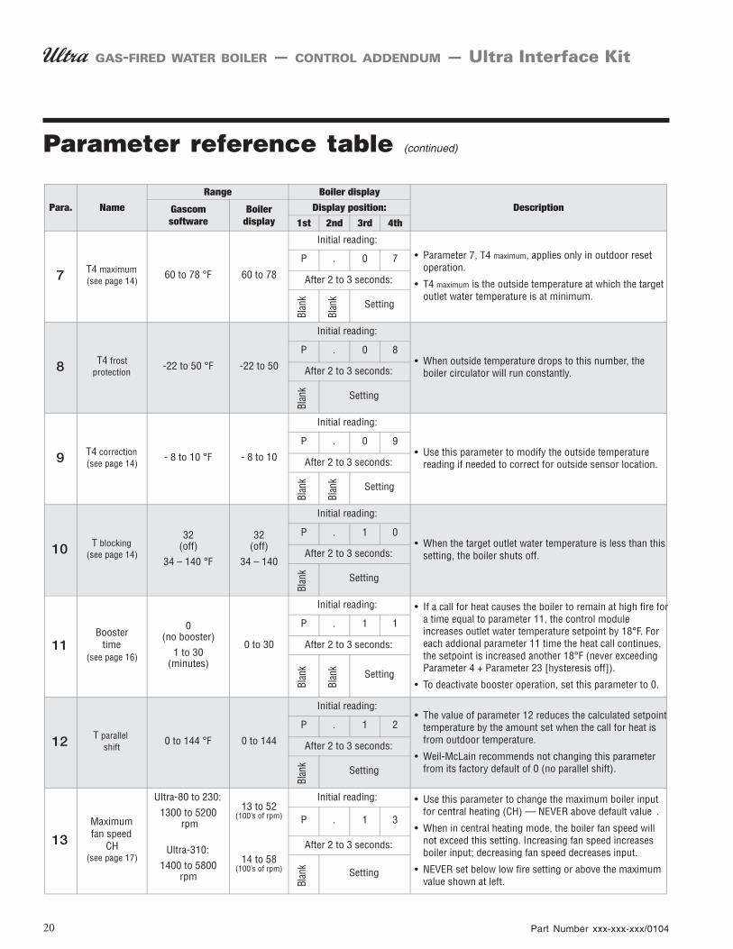
Parameter reference table
20 Part Number xxx-xxx-xxx/0104
GAS-FIRED WATER BOILER — CONTROL ADDENDUM — Ultra Interface Kit
Parameter reference table (continued)

Part number 550-100-040/0804 21
GAS-FIRED WATER BOILER — CONTROL ADDENDUM — Ultra Interface Kit
Parameter reference table (continued)

Part number 550-100-040/080422
GAS-FIRED WATER BOILER — CONTROL ADDENDUM — Ultra Interface Kit
Parameter reference table (continued)

Part number 550-100-040/0804 23
GAS-FIRED WATER BOILER — CONTROL ADDENDUM — Ultra Interface Kit
Parameter reference table (continued)
Part number 550-100-040/080424
GAS-FIRED WATER BOILER — CONTROL ADDENDUM — Ultra Interface Kit
Parameter reference table (continued)
Part number 550-100-040/0804 25
GAS-FIRED WATER BOILER — CONTROL ADDENDUM — Ultra Interface Kit
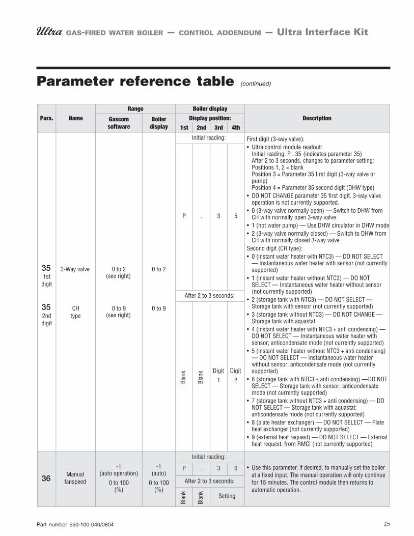
Parameter reference table (continued)

Part number 550-100-040/080426
GAS-FIRED WATER BOILER — CONTROL ADDENDUM — Ultra Interface Kit
Parameter reference table (continued)

Part number 550-100-040/0804 27
GAS-FIRED WATER BOILER — CONTROL ADDENDUM — Ultra Interface Kit
Parameter reference table (continued)
Part number 550-100-040/080428
GAS-FIRED WATER BOILER — CONTROL ADDENDUM — Ultra Interface Kit