Gas Fired Wall Mounted Combination Boiler - … 105e user guide.pdf · Baxi Combi 80e & 105e Gas...
12
Baxi Combi 80e & 105e Gas Fired Wall Mounted Combination Boiler User’s Operating Instructions Please keep these instructions safe. Should you move house, please hand them over to the next occupier.
Transcript of Gas Fired Wall Mounted Combination Boiler - … 105e user guide.pdf · Baxi Combi 80e & 105e Gas...
Baxi Combi 80e & 105eGas Fired Wall Mounted Combination Boiler
User’s OperatingInstructions
Please keep these instructions safe.Should you move house, please hand
them over to the next occupier.
2
Baxi UK Limited is one of the leading manufacturers
of domestic heating products in the UK.
Our first priority is to give a high quality service to our
customers. Quality is designed into every Baxi product
- products which fulfil the demands and needs of
customers, offering choice, efficiency and reliability.
To keep ahead of changing trends, we have made a
commitment to develop new ideas using the
latest technology - with the aim of continuing to
make the products that customers want to buy.
Everyone who works at Baxi has a commitment to
quality because we know that satisfied customers
mean continued success.
We hope you get a satisfactory service from Baxi. If
not, please let us know.
Natural Gas
Baxi Combi 80eG.C.No 47 075 06
Baxi Combi 105eG.C.No 47 075 08
Baxi is a BS-EN ISO 9001Accredited Company
The boiler meets the requirements of Statutory Instrument“ The Boiler (Efficiency) Regulations 1993 No 3083” and isdeemed to meet the requirements of Directive 92/42/EECon the energy efficiency requirements for new hot waterboilers fired with liquid or gaseous fuels:-
Type test for purpose of Regulation 5 certified by: Notified Body 0051.
Product/Production certified by:Notified Body 0051.
For GB/IE only.
Where fitted, user label for optional timer to be applied here
1.0 Warnings
3
1.1 Safe Installation
1. The appliance is suitable for installation only inG.B. and I.E. and should be installed inaccordance with the rules in force. For Irelandinstall in accordance with I.S.813 “INSTALLATION
OF GAS APPLIANCES”. The installation must becarried out by a CORGI Registered Installer orother registered competent person and be inaccordance with the relevant requirements of GAS
SAFETY (Installation and Use) REGULATIONS mostrecent edition, the BUILDING REGULATIONS issuedby the Department of the Environment, BUILDING
STANDARDS (Scotland) (Consolidation)REGULATIONS issued by the Scottish DevelopmentDepartment and the LOCAL BUILDING
REGULATIONS. Where no specific instructions aregiven, reference should be made to the relevantBRITISH STANDARD CODES OF PRACTICEand INSTALLATION SPECIFICATIONS.
2. This appliance must be installed inaccordance with the manufacturer’sinstructions and the rules in force, and onlyused in a suitably ventilated location.
3. Read the instructions before installing orusing this appliance.
4. Any purpose provided ventilation should bechecked periodically to ensure that it is free fromobstruction.
IMPORTANT - The addition of anything thatmay interfere with the normal operation of theappliance without the express writtenpermission of Baxi UK Limited could invalidatethe appliance warranty and infringe the GAS
SAFETY (Installation and Use) REGULATIONS.
1.2 In case of gas leaks
1. If a gas leak is found or suspected, turn off thegas supply at the meter immediately and at theisolating valve on the boiler if possible. Contactyour Installer or Transco (under 'Gas' in thephone directory).
1.3 Servicing your Appliance
1. For reasons of safety and economy yourappliance should be serviced annually. Servicingmust be performed by a competent person. YourInstaller or British Gas Service will be able toadvise you.
1.4 Electricity Supply
1. THIS APPLIANCE MUST BE EARTHED.
2. A standard 230V ~ 50Hz supply is required.The appliance must be protected by a 3 ampfuse.
Never Hang Flammable Items Over The
Appliance
STANDARDB.S. 6891B.S. 5440: Pt 1B.S. 5440: Pt 2B.S. 5546
B.S. 7074
B.S. 5449B.S. 6798
SCOPEGas Installation.Flues.Air Supply.Installation of hot water suppliesfor domestic purposes.
Expansion vessels and ancillaryequipment for sealed water systems.
Forced circulation hot water systems.Installation of gas fired hot waterboilers.
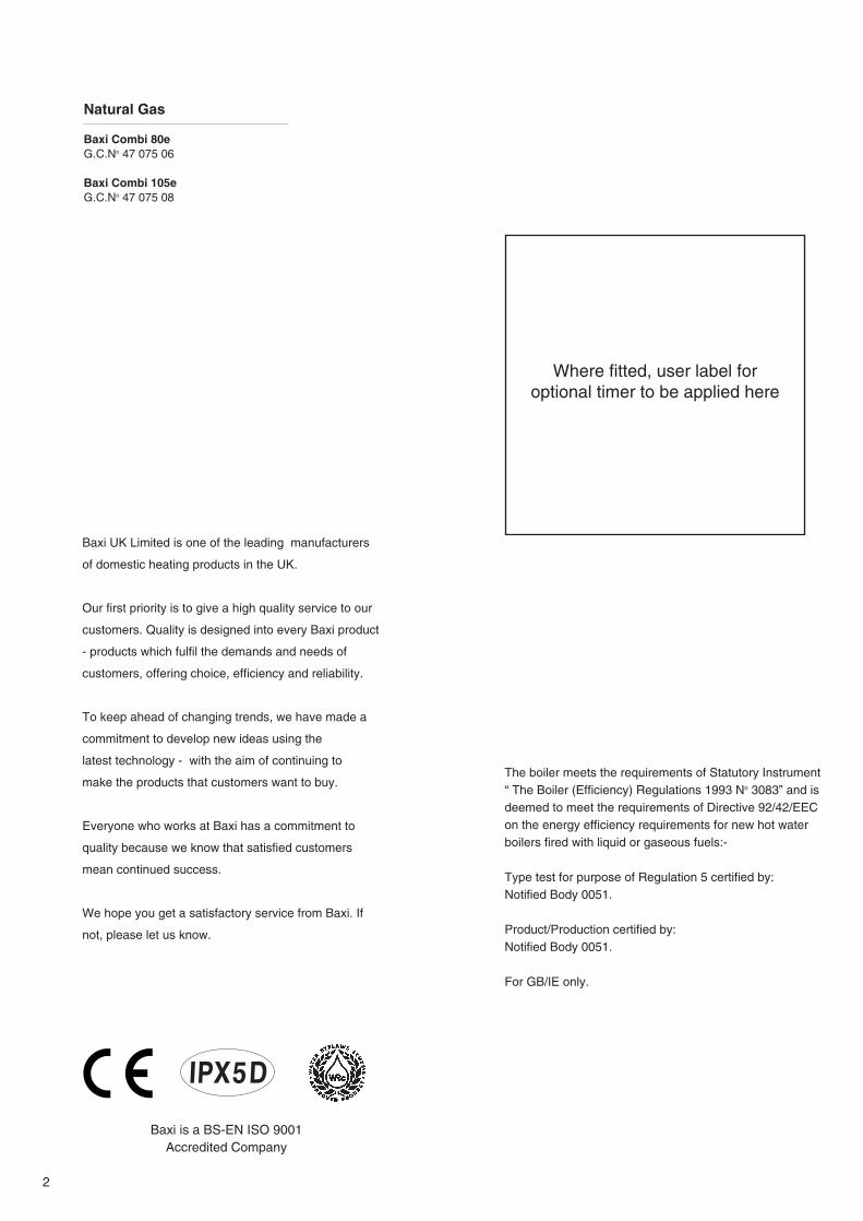
IN AN EMERGENCY
If a water or gas leak occurs or is suspected, the boiler can beisolated at the inlet valves as follows;
1. Turn off the electrical supply and turn the selector switch onthe facia box to the OFF position.
2. Using a suitable open ended spanner or screwdriver turn thesquare on the gas tap to the left to isolate the gas supply at theboiler (Fig. 1).
3. The isolating valves are positioned under the boiler and can beclosed by turning their taps to the right towards the wall (Fig. 2).
4. Call your Service Engineer as soon as possible.
“Benchmark” Installation, Commissioning and ServiceRecord Log Book
Please ensure that your installer has completed the Installationand Commissioning sections of the Log Book and hands the LogBook over. The details of the Log Book will be required in theevent of any warranty work. Keep the Log Book in a safe placeand ensure that the relevant sections are completed at eachsubsequent regular service visit.
Gas Tap
Heating Flow, HeatingReturn and Mains
Water InletIsolating Valves
Fig. 1
Fig. 2
All CORGI registered installers carry a CORGI identification cardand have a registration number. Both should be recorded in yourboiler Log Book. You can check your installer is registered bytelephoning 01256 372300 or writing to:-1 Elmwood, Chineham Business Park,Crockford Lane, Basingstoke,RG24 8WG

2.0 Introduction
4
2.1 Introduction
1. Your Baxi Combi 80e or 105e is a gas fired,room sealed, powered flue combination boiler,providing central heating for your home andmains fed domestic hot water to taps andshower. It is fully automatic and does not have apilot light.
2. Priority is given to the hot water mode - whena hot water tap is turned on the supply of heat tothe central heating circuit is interrupted.
2.2 Facia Panel
1. The facia panel is behind the hinged lowerdoor. As well as the on/off/reset selector switch,temperature control knobs and pressure gauge,the facia incorporates ten neon indicator lights.
2. Neons 12 to 15 indicate the operational statusof the boiler. Neons 6 to 11 have a dual function,indicating the temperature of the central heatingwater when constantly illuminated. If a faultdevelops the appropriate neon will begin toflash. Refer to Sections 3.3 to 3.7.
30° 40° 50° 60° 70° 80°2
1
0 4
3
bar
Fig. 3
30° 40° 50° 60° 70° 80°
1. On/Off/Reset Selector Switch
2. Central Heating Temperature Control
3. Hot Water Temperature Control
4. Central Heating System Pressure Gauge
5. Optional Integral Timer Position
Neon Indicators6. Flame Failure
7. Safety Thermostat Activated
8. Fault on Fan or Flue
9. Fault on Pump or Low System Pressure
10. Fault on Hot Water Sensor
11. Fault on Central Heating Sensor
12. Power On
13. Domestic Hot Water Mode
14. Central Heating Mode
15. Burner On
When neons 6 to 11 are constantly illuminated,they indicate the temperature of the centralheating water
321 4 5
6 7 8 9 10 11
12 13 14 15
KEY TO FACIA PANEL (Fig. 3)
3.0 Operating the Boiler
5
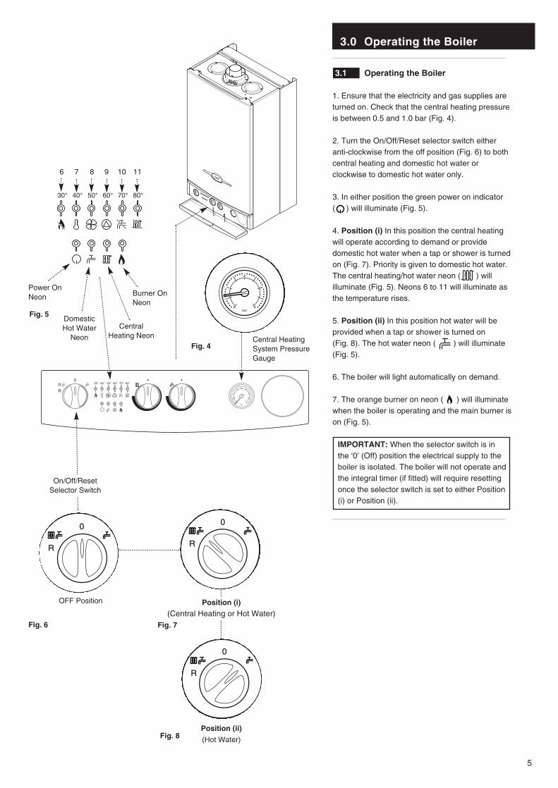
3.1 Operating the Boiler
1. Ensure that the electricity and gas supplies areturned on. Check that the central heating pressureis between 0.5 and 1.0 bar (Fig. 4).
2. Turn the On/Off/Reset selector switch eitheranti-clockwise from the off position (Fig. 6) to bothcentral heating and domestic hot water orclockwise to domestic hot water only.
3. In either position the green power on indicator ( ) will illuminate (Fig. 5).
4. Position (i) In this position the central heatingwill operate according to demand or providedomestic hot water when a tap or shower is turnedon (Fig. 7). Priority is given to domestic hot water.The central heating/hot water neon ( ) willilluminate (Fig. 5). Neons 6 to 11 will illuminate asthe temperature rises.
5. Position (ii) In this position hot water will beprovided when a tap or shower is turned on (Fig. 8). The hot water neon ( ) will illuminate(Fig. 5).
6. The boiler will light automatically on demand.
7. The orange burner on neon ( ) will illuminatewhen the boiler is operating and the main burner ison (Fig. 5).
IMPORTANT: When the selector switch is inthe ‘0’ (Off) position the electrical supply to theboiler is isolated. The boiler will not operate andthe integral timer (if fitted) will require resettingonce the selector switch is set to either Position(i) or Position (ii).
30° 40° 50° 60° 70° 80°2
1
0 4
3
bar
Position (ii)
(Hot Water)
Fig. 7
Fig. 8
OFF Position
Fig. 6
Fig. 5
Fig. 4
2
1
0 4
3
bar
Power On Neon Burner On
Neon
Central HeatingSystem PressureGauge
Position (i)
(Central Heating or Hot Water)
On/Off/ResetSelector Switch
Central Heating Neon
DomesticHot Water
Neon
30° 40° 50° 60° 70° 80°
6 7 8 9 10 11
3.0 Operating the Boiler
6
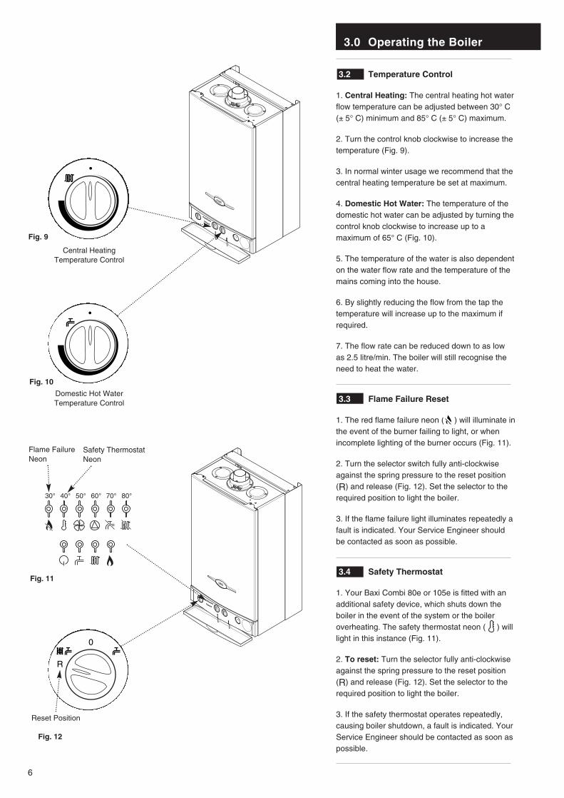
3.2 Temperature Control
1. Central Heating: The central heating hot waterflow temperature can be adjusted between 30° C(± 5° C) minimum and 85° C (± 5° C) maximum.
2. Turn the control knob clockwise to increase thetemperature (Fig. 9).
3. In normal winter usage we recommend that thecentral heating temperature be set at maximum.
4. Domestic Hot Water: The temperature of thedomestic hot water can be adjusted by turning thecontrol knob clockwise to increase up to amaximum of 65° C (Fig. 10).
5. The temperature of the water is also dependenton the water flow rate and the temperature of themains coming into the house.
6. By slightly reducing the flow from the tap thetemperature will increase up to the maximum ifrequired.
7. The flow rate can be reduced down to as lowas 2.5 litre/min. The boiler will still recognise theneed to heat the water.
3.3 Flame Failure Reset
1. The red flame failure neon ( ) will illuminate inthe event of the burner failing to light, or whenincomplete lighting of the burner occurs (Fig. 11).
2. Turn the selector switch fully anti-clockwiseagainst the spring pressure to the reset position(R) and release (Fig. 12). Set the selector to therequired position to light the boiler.
3. If the flame failure light illuminates repeatedly afault is indicated. Your Service Engineer shouldbe contacted as soon as possible.
3.4 Safety Thermostat
1. Your Baxi Combi 80e or 105e is fitted with anadditional safety device, which shuts down theboiler in the event of the system or the boileroverheating. The safety thermostat neon ( ) willlight in this instance (Fig. 11).
2. To reset: Turn the selector fully anti-clockwiseagainst the spring pressure to the reset position(R) and release (Fig. 12). Set the selector to therequired position to light the boiler.
3. If the safety thermostat operates repeatedly,causing boiler shutdown, a fault is indicated. YourService Engineer should be contacted as soon aspossible.
Domestic Hot WaterTemperature Control
Fig. 9
Central HeatingTemperature Control
Fig. 10
Reset Position
Fig. 12
30° 40° 50° 60° 70° 80°
Flame FailureNeon
Fig. 11
Safety ThermostatNeon
3.0 Operating the Boiler
7
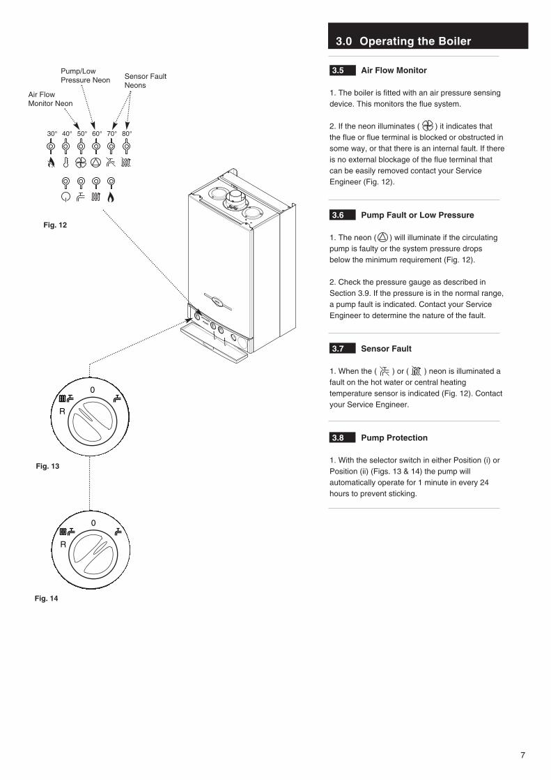
3.5 Air Flow Monitor
1. The boiler is fitted with an air pressure sensingdevice. This monitors the flue system.
2. If the neon illuminates ( ) it indicates thatthe flue or flue terminal is blocked or obstructed insome way, or that there is an internal fault. If thereis no external blockage of the flue terminal thatcan be easily removed contact your ServiceEngineer (Fig. 12).
3.6 Pump Fault or Low Pressure
1. The neon ( ) will illuminate if the circulatingpump is faulty or the system pressure dropsbelow the minimum requirement (Fig. 12).
2. Check the pressure gauge as described inSection 3.9. If the pressure is in the normal range,a pump fault is indicated. Contact your ServiceEngineer to determine the nature of the fault.
3.7 Sensor Fault
1. When the ( ) or ( ) neon is illuminated afault on the hot water or central heatingtemperature sensor is indicated (Fig. 12). Contactyour Service Engineer.
3.8 Pump Protection
1. With the selector switch in either Position (i) orPosition (ii) (Figs. 13 & 14) the pump willautomatically operate for 1 minute in every 24hours to prevent sticking.
30° 40° 50° 60° 70° 80°
Air Flow Monitor Neon
Pump/LowPressure Neon Sensor Fault
Neons
Fig. 12
Fig. 13
Fig. 14

3.0 Operating the Boiler
8
3.9 Central Heating System Pressure
1. The water pressure in the central heatingsystem is indicated by the pressure gauge.
2. With the system cold and the boiler notoperating the pressure should be between 0.5and 1.0 bar. During operation the pressureshould not exceed 2.5 bar, and will normally bebetween 1.0 and 2.0 (Figs. 15 & 16).
3. A pressure of 3 or greater indicates a fault.The safety pressure relief valve will operate, at apressure of 3 (Fig. 17). It is important that yourService Engineer is contacted as soon aspossible.
4. The MINIMUM pressure for correct operationis 0.5. If the pressure falls below 0.5, this mayindicate a leak on the central heating system(Fig. 18).
5. The system must be re-pressurised by yourService Engineer.
3.10 To Shut Off the Boiler
1. For short periods: Turn the selector switch tothe OFF position (Fig. 19).
2. For long periods: Turn off the selector switch(Fig.19), electricity and gas supplies.
If your home is to be left unoccupied for longperiods during cold weather the boiler andwhole system should be drained unless thereis additional frost protection.
3. Your installer will advise you about frostprotection and draining the system.
IMPORTANT: When the selector switch is inthe ‘0’ (Off) position the electrical supply to theboiler is isolated. The boiler will not operateand the integral timer (if fitted) will requireresetting once the selector switch is set toeither Position (i) or Position (ii).
3.11 Frost Protection Mode
1. The frost protection feature will operate whenthe selector switch is in the central heating anddomestic hot water mode.The gas and electrical supplies to the boiler mustbe on and the system pressure must be withinthe range described in Section 3.9.
2. If the system temperature falls below 5°C, thenthe boiler will fire until the water temperature hasbeen raised.
3. Further frost protection can be incorporated byusing a frost thermostat to protect the wholesystem.
2
1
0 4
3
bar
2
1
0 4
3
bar
2
1
0 4
3
bar
2
1
0 4
3
bar
ON/OFFSelector Switch
OFF Position
Fig. 19
Normal Pressure (when cold)
Normal Pressure (operating)
Fig. 15
Fault
Fig. 16
Below Minimum
Fig. 17
Fig. 18
Pressure Gauge
4.0 Clearances and Check List
9
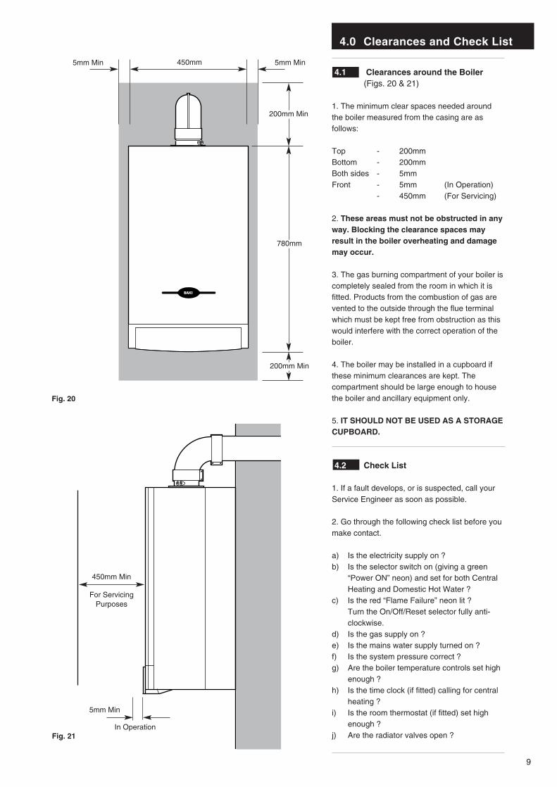
4.1 Clearances around the Boiler(Figs. 20 & 21)
1. The minimum clear spaces needed aroundthe boiler measured from the casing are asfollows:
Top - 200mmBottom - 200mmBoth sides - 5mmFront - 5mm (In Operation)
- 450mm (For Servicing)
2. These areas must not be obstructed in anyway. Blocking the clearance spaces mayresult in the boiler overheating and damagemay occur.
3. The gas burning compartment of your boiler iscompletely sealed from the room in which it isfitted. Products from the combustion of gas arevented to the outside through the flue terminalwhich must be kept free from obstruction as thiswould interfere with the correct operation of theboiler.
4. The boiler may be installed in a cupboard ifthese minimum clearances are kept. Thecompartment should be large enough to housethe boiler and ancillary equipment only.
5. IT SHOULD NOT BE USED AS A STORAGECUPBOARD.
4.2 Check List
1. If a fault develops, or is suspected, call yourService Engineer as soon as possible.
2. Go through the following check list before youmake contact.
a) Is the electricity supply on ?b) Is the selector switch on (giving a green
“Power ON” neon) and set for both Central Heating and Domestic Hot Water ?
c) Is the red “Flame Failure” neon lit ? Turn the On/Off/Reset selector fully anti- clockwise.
d) Is the gas supply on ?e) Is the mains water supply turned on ?f) Is the system pressure correct ?g) Are the boiler temperature controls set high
enough ?h) Is the time clock (if fitted) calling for central
heating ?i) Is the room thermostat (if fitted) set high
enough ?j) Are the radiator valves open ?
780mm
450mm
200mm Min
5mm Min5mm Min
5mm Min
450mm Min
For ServicingPurposes
Fig. 20
Fig. 21In Operation
200mm Min

5.0 Cleaning, Spares & Guarantee
10
5.1 Cleaning the Outercase
The painted panels should be wiped with a dampcloth and then dried completely. DO NOT USEABRASIVE CLEANING AGENTS.
5.2 Spare Parts
IMPORTANT - Only a competent personshould be used to service or repair this boiler.
1. Any repairs to the boiler will usually be theresponsibility of the Installer during theguarantee period after which spare parts may beobtained through approved Baxi stockists ifrequired.
2. Quote the appliance name, model numberand where possible the part number whenordering spares. A parts list is included in theInstallation and Servicing Instructions.
3. The name, model number and serial numbercan be found on the information label on theback of the hinged lower door (Fig. 22).
5.3 Guarantee
1. Your Baxi Combi 80e or 105e is designed andproduced to meet all the relevant Standards.
2. Baxi UK Limited provide a 12 monthguarantee on the boiler. The guarantee operatesfrom the date installation is completed for thecustomer who is the original user.
3. To maximise the benefit from our guaranteewe urge you to return the reply-paid guaranteeregistration.
4. This does not in any way prejudice your rightsat Common Law. Such rights between thecustomer and the installer or supplier from whomthe unit was purchased remain intact.
Any component or part which becomesdefective during the guarantee period as aresult of faulty workmanship or materialwhilst in normal use will be repaired orreplaced free of charge.
Information Label
Fig. 22
11
Baxi UK Limited manufacture a comprehensive rangeof products for the domestic heating market.
Gas Central Heating Boilers(Wall, Floor and Fireside models).
Independent Gas Fires.
Renewal Firefronts.
Gas Wall Heaters.
Solid Fuel Fires.
If you require information on any of these products,please write, telephone or fax to the Sales Department.
Baxi UK LimitedBrownedge Road
Bamber Bridge PrestonLancashirePR5 6SN
www.baxi.com
After Sales Service08706 096 096
Comp No 247939 - Iss 3 - 6/01
921.653.1