Gartside Dam 2012 Engineer’s Report of Periodic...
44
Gartside Dam 2012 Engineer’s Report of Periodic Inspection By State Water Project Bureau, Montana DNRC For Montana DFWP September 20, 2012
Transcript of Gartside Dam 2012 Engineer’s Report of Periodic...

Gartside Dam
2012 Engineer’s Report of Periodic Inspection
By
State Water Project Bureau, Montana DNRC For
Montana DFWP
September 20, 2012

Table of Contents
Design Review Appendix A – Loss-of-Life Calculations Appendix B – Discussion 1998 slump Area Monument Pins Appendix C – Piezometer Critical Alerts Discussion Appendix D – Piezometer Data

1
2012 Gartside 5 Year Design Review for Operating Permit Renewal
Richard Misplon, P.E. Overview
Gartside Dam is located on Crane Creek in Richland County. The project is approximately 10 miles southwest of Sidney, Montana and about one mile northwest (upstream) of the town of Crane, Montana. The dam is owned by the Montana Department of Fish, Wildlife and Parks (DFWP) and is managed by the Parks Division of the DFWP. The DFWP Miles City Regional Office manages and operates the dam. The DFWP is responsible for repairs and maintenance of the dam. The DNRC State Water Projects Bureau inspects the dam annually and provides engineering assistance as needed. The dam is believed to originally have been a beaver dam that was covered with soil by a local rancher in about 1900 to provide a more adequate water supply for cattle. The dam was enlarged in the 1930’s to a height of 6 or 7 feet. The dam was raised further in 1955 and again in 1962 to its current height of 31 feet1. In 1982 a large depression formed around the drop inlet structure causing damage to both the embankment and the drop inlet structure. The dam was breached by DNRC in 1985 to alleviate dam safety concerns. The breach consisted of a channel excavated through the embankment and the outlet works was removed1. In 1990 the dam embankment was reconstructed. The repair included adding a 10-foot wide berm across the downstream toe of the dam, flattening the upstream slope of the embankment, and adding cobble slope protection. The current configuration of the dam is a curved-axis earth-filled dam 31 feet high and 1350 feet long with a crest width of 28 feet2.
Categorized as a High Hazard Facility In November of 1980, the United States Army Corps of Engineers (COE) concluded that the Gartside Dam was a High Hazard facility1. Because of that hazard determination the facility must be operated under the provisions of an Operating Permit issued by the Dam Safety Section of the Montana DNRC. The current Operating Permit for Gartside expires October 10, 2012 or 90 days after the facility inspection, whichever comes first. The Operating Permit must be renewed in order for the DFWP to continue operation of the facility.

2
Downstream Hazard and Loss of Life Analysis
Montana utilizes a risk based spillway standard. The reservoir is required to safely pass a design flood with an annual reoccurrence interval of 1,000 times the anticipated Loss Of Life should the dam fail. The 2007 Loss of Life analysis as prepared by Bill Fullerton and included as Appendix A in the 2007 Gartside Dam Engineer’s Report of Periodic Inspection9 was reviewed. The Graham Procedure Fullerton used is the one currently accepted. His assumptions were reasonable and accepted for this review. Since 2007 “Dam Safety Program, Technical Note 2, Loss Of Life Determination For Spillway Capacity Analysis, August 2010” 10 has been issued providing additional direction for determining the “Population At Risk (PAR)”. There has been some non-residential development in the inundation area of a Clear Weather Breach of the dam since 2007. Bill Fullerton’s Loss of Life analysis and an addendum to that analysis with the revisions for 2012 have been attached as “Appendix A”. The 2012 revised Population-At-Risk was determined to be 24, with a corresponding Loss-of-Life of 0.24.
Hydrologic Adequacy The spillway has a calculated capacity of 13000 cfs when the water is at the dam crest elevation, with no freeboard (page 14 of HKM’s summary in reference 2). The design flood used for the spillway design in the 1990 rehabilitation project was one-half the probable maximum flood (PMF) at a flow rate of 9400 cfs1. HKM’s 1991 spillway capacity computations have been reviewed for this report.2 HKM used HEC-2 to perform their spillway calculations. This was the appropriate program in 1991 and in for this purpose is still appropriate. Input data was reviewed and the values were reasonable.
The results of the LOL calculations in Appendix A are used to check the spillway design to determine if the spillway has adequate capacity. The current design criteria is that the spillway should have a capacity to pass a flood flow with a recurrence interval of a flood that corresponds to 1 life lost per thousand years (i.e. LOL=1 pass 1000 year flood, LOL=2 pass 2000 year flood, etc.), with the default that no matter how low the LOL is, the spillway for this category of dam must be able to handle the 500 year flood 4. With a Loss Of Life of 0.24 the facility at Gartside falls into this default category, in order to meet design standards the spillway must have adequate capacity to convey the 500-year flood.

3
In 2007 William Fullerton of the DNRC calculated flood-frequency values and determined the 500 year flood flow for Gartside using USGS Water Resources Investigations Report 03-4308, which is cited as reference 5. The procedures developed in that report are generically referred to as the “Parrett Method” and is considered current practice. The Flood-Frequency/Flow relationship calculated in 2007 was used for this design review. Fullerton developed an “Excel” spreadsheet to apply basin coefficients from “Parrett” to the Crane Creek watershed9.
Shown below are Fullerton’s flood-frequency values for Gartside computed using the Parrett method:
Flood-Frequency/Flow Values for Gartside
Return Interval (Years) Peak Flow (cfs) (Parrett)
2 156 5 584 10 1097 25 2013 50 2909 100 3996 200 5186 500 7073
Design 50% PMF 94001
Because the calculated capacity of the spillway at 50% of the PMF (9400 cfs) is greater than the 500 year predicted flood of 7073 cfs the existing spillway meets Dam Safety rules regarding capacity.
Spillway Structural Adequacy
The Spillway consists of a trapezoidal channel excavated into the right abutment. Because the natural material where the spillway was constructed was susceptible to erosion, the design provided for the spillway to be lined with a one-foot thick lift of soil-cement that was placed over a 6-inch layer of gravel. Within the gravel layer is a 4-inch diameter PVC drain that is fed by 3-inch diameter laterals. Not unexpectedly, within several years of construction the soil-cement began to show pattern cracking, assumed to be caused principally by temperature changes in the unreinforced soil-cement. In 1999 this cracking was mapped by Rob Kingery of the Montana DNRC and an AutoCAD drawing was prepared to show the nature and extent of the cracking in 1999. The electronic file for that drawing has been archived by the Montana DNRC is located within their common directory at:

4
K:\WATER_PROJECTS\PROJECTS\DFWP-Dams\Gartside Dam\Acad\spillway.dwg The soil cement spillway surface is still structurally sound in 2012, but cracking and spalling continue to be a problem. A one-time repair project and follow up annual repairs have been recommended to maximize the life of the surface.
The Spillway meets existing Dam Safety criteria regarding structural adequacy.
Low-level Outlet Hydraulic and Structural Adequacy
• Description of low-level outlet works:
The low-level outlet conduit is a 30-inch diameter circular, precast, reinforced concrete pipe approximately 200 feet long. A 16-inch square inclined slide gate controls the discharge through the conduit. The downstream end of the conduit terminates at a flared wall outlet-stilling basin. The calculated capacity of the outlet with the reservoir at the spillway crest is approximately 33 cfs and approximately 40 cfs when the reservoir is at the crest of the dam. The downstream face of the gate is vented to the atmosphere with a 3-inch vent pipe.11
The slide gate is a 16 x 16 Waterman Model S-5000 –F Sluice Gate and the 1 1/2-inch diameter stem that operates the gate is enclosed in a 2 ½ -inch diameter galvanized encasing pipe which is buried on the upstream face of the dam. The annular space between the stem and the encasing pipe is filled with hydraulic oil. An oil fill plug is located at the upper end of the encasing pipe to check the oil level and replenish oil, if needed. A check of the oil level in the encasing pipe should be an item in the annual inspection of the facility.
In 1995 the gate stem separated from the outlet gate and the reservoir contents were lost. Once the gate and stem were repaired, stop nuts were placed on the control stem to prevent the gate from being closed too tight or opened too much.
The gate control is a 24-inch diameter hand wheel located in a 5 foot x 5 foot subterranean concrete vault located along the upstream crest of the dam. The vault is covered with a steel plate that is hinged and secured with a lock to prevent unauthorized access.
• In 2010 a problem with intermittent binding of the gate operator was reported. The operator binds up during the last few inches of closure. If pressure is maintained on the operator wheel eventually the binding is overcome and the gate can be closed. By 2011 the forces on the operator mounting plate had warped it and loosened it’s mounting from the vault wall. Since then the mounting plate has been re-fastened to the wall and the binding issues have improved but not gone away. A heavier duty mounting plate has been fabricated and is scheduled to be fastened to the vault wall with four rather than the original two mounting

5
studs in the fall of 2012. If this does not cure the problem the DNRC-FWP Dam Engineer will determine methods to find the cause of the problem and to correct it.
• The 2012 inspection found the invert of the first joint of the outlet conduit upstream of the stilling basin has opened about 2”. (See the 2012 Annual Dam Safety Inspection Report, Reference # 12) It is likely the joint has been compromised. The joint is to be sealed in the fall of 2012 using a fast setting hydraulic grout. No other joints in the conduit show significant gaps. That would indicate the likely cause of the gap is the rising of the outlet end of the conduit with a corresponding shift of the concrete stilling basin. The sealed joint will be monitored to see if the situation is stable. Elevations of the four corners of the stilling basin will be monitored for vertical movement. If movement is still taking place further investigations will be conducted to determine the cause.
• The hydraulic adequacy of the low level outlet was investigated in Fullerton’s 2007 report9. Fullerton developed an “Excel” spreadsheet to incrementally drain the reservoir using curve fitting subroutines to express the mathematical relationships between head vs. gate discharge and reservoir level vs. storage. The results indicate the reservoir could be emptied in less than 10 days, well within the recommended guidelines given in Reference #8. Fullerton’s work was reviewed and accepted along with his conclusions.
Embankment and Embankment Stability
• Piping - During studies leading to the “Rehabilitation Design Report”, 8 holes were bored and 12 test pits were dug to determine the nature of the foundation materials. Those studies concluded that the foundation materials were predominantly sands and gravels overlaying bedrock of siltstone/shale, with bedrock being at a depth of up to 45 feet deep. Because the sands and gravels were quite permeable the rehabilitation plans contained details for a filter blanket installed between the toe of the original embankment slope and a new Toe Berm to control the seepage as it exits the foundation and abutment areas. (See Gartside Dam Monitoring Wells drawing Appendix C)
The filter was designed using Jean Paul Giroud’s methods as discussed in “Designing with Geotextiles”, Jul-Aug 1981. In 2007 Fullerton investigated the filter design methods and although there had been some minor changes in the methods since 1991 the original geotextile was appropriate for the updated methods9. Were this filter to be designed today standards call for gravel filters rather than geotextile filters because of the problem of the geotextile becoming clogged. There is no evidence that the installed geotextile filter is not working. If the filter were not working we would expect to see seepage at the junction of the original

6
downstream slope of the dam and the toe berm. We would also expect to see a rising level in Piezometer DP-1. Neither has been observed. Observation of both of these areas is part of the normal inspection routine at Gartside. If either symptom is observed in the future further investigation will be necessary to determine if filter failure is occurring. • Seismic – The 1985 Gartside Rehabilitation Study Report which is cited as Reference #1 contains the following narrative regarding seismic design:
“Gartside Reservoir is located in seismic zone 1. Zone 1 is defined as exhibiting potential for minor damage from seismic action. Only two events of intensity 4 to 6 have been recorded within 100 miles of the reservoir. Seismicity does not appear to be a critical factor in consideration of the stability of the embankment.”
In 2004 the Montana DNRC published a proposed design methodology for seismic design of dams that utilized ground-shaking maps. Although the DNRC design methods have not yet reached the status of “Administrative Rules”, they do reflect current seismic design practice. The present minimum design standard is the 2500 year seismic event. Using the Peak Horizontal Acceleration at Ground Surface maps from the proposed regulations the estimated PHA is < 0.1g for the 2500 year event and 0.1g-0.2g for the 5000 year event. In the November 29, 2007 cover letter to Brian Holling (RE: Operation Permit Renewal of Gartside Dam) Michele Lemieux further refined the estimated PHA as 0.08g for the 2500 year event and 0.11g for the 5000 year event. It is likely the new regulations will be finalized and adopted in 2013. It is also probable that the new regulations will require design for State dams to the 5000 year event. In the proposed regulations a PHA of less than 0.1g will not require further action. Since the PHA for the 5000 year event is in excess of 0.1g it is likely that the new regulations will require Gartside Dam to be evaluated on criteria included in the proposed regulations to determine if further seismic analysis is required. Depending on the outcome of the evaluation either no further action will be necessary or a Seismic Analysis will need to be performed. Since the present standard is the 2500 year event no further seismic analysis is required at this time. If the new regulations adopt the 5000 year event as the standard an evaluation will have to be made to determine if a Seismic Analysis of the dam will need to be performed.
• Stability - An embankment stability analysis was conducted by HKM Associates in conjunction with design performed for the 1991 rehabilitation project. Rob Kingery, of the Montana DNRC performed supplemental stability analyses calculations in 1998 using actual observed piezometric elevations and concluded that the in service steady state safety factor was 1.55 which is greater than the

7
minimum recommended safety factor of 1.507. Since 1998 there have been no significant long term changes in the piezometer readings that would affect this analysis. • Sudden Drawdown - A “Sudden Drawdown” stability analysis was conducted by HKM Associates in conjunction with design performed for the 1991 rehabilitation project. That analysis concluded that the safety factor for “Sudden Drawdown” was 1.70 which is greater than the minimum recommended safety factor of 1.22.
Instrumentation
• During the 1998 annual condition survey some possible slumping was detected on the downstream face of the dam6. An array of survey monuments were installed in 1998 to provide data about horizontal and vertical movements in the portion of the embankment that seemed to be moving and to determine if those movements were surface phenomena or deep-seated. In 2000 it was determined that the accuracy of the measurements was not sufficient to be meaningful using a total station. It was decided that level elevations would be used from then on to determine accurate vertical elevations. Vertical Elevations were determined by level in 2000, 2001, 2007 & 2012. Tabulated records of survey monument elevations are included in Appendix B. The surface movement is believed to be superficial.
• The monuments have been monitored at least annually for the past 14 years. No significant movement has been noted in the surveyed measurements. Neither has there been any visual evidence of movement. There is no evidence that the 1998 movement was anything other than a surface phenomenon. The area is considered to be stable. Unless further evidence of movement is noted, measurements of the elevations of the monuments are no longer necessary. The area will continue to be monitored visually, as is the rest of the structure, annually during inspection. A discussion of the results of the monitoring is included in Appendix B • In 2003 Dam Safety made a recommendation that “Alert” levels be established for the piezometers on Gartside Dam (Letter dated January 24, 2003 to Ken Phillips, FWP from Michele Lemieux, DNRC RE: Approval of Operation Permit for Gartside Dam). The State Water Projects Bureau has updated its monitoring data recording procedures. With the revised data reporting procedures we feel the present system of multiple levels of review by qualified personnel will safeguard the structure. Critical Alert Levels are not required on any of our other dams. In any event it would be difficult to establish alert levels that would be meaningful. We request Dam Safety’s recommendation to establish Alert Levels for the Gartside Dam Piezometers be dropped in favor of the existing updated reporting and review procedures. See Appendix C for a discussion of the issue.

8
Condition of Facility
The following personnel conducted an on-site inspection of the facility on June 26, 2012:
Richard Misplon, P.E. (DNRC Rehab Section); Robert Kingery, P.E. (DNRC Rehab Section); Marvin Cross, CES. (DNRC- -Havre); Sterling Sundheim, CES. (DNRC-Lewistown); Cathy Stewart (DFWP Parks Supervisor– Miles City) Vickie Eskridge (DFWP Dam Tender- Crane)
The 2012 Annual Inspection Report has been prepared and distrubuted12. Recommendations to be completed in 2012:
• Assist DNRC in repairs to outlet Conduit. • Install revised operator mounting plate.
Long-Term Recommendations:
• Perform maintenance recommendations identified in the 2012 Annual Inspection Report12.
References
1. HKM Associates, January 1985, “Gartside Dam Rehabilitation Study”.
2. HKM Associates, July 1991, “Gartside Dam Rehabilitation Design Report”.
3. Graham, Wayne H., “A Procedure for Estimating Loss of Life Caused by a Dam Failure”, US Bureau of Reclamation Dam Safety Office, Publication DSO-99-06 September 1999.
4. State of Montana, “Administrative Rules of Montana”, Dam Safety Rules, January 1989.
5. Parrett, Charles and John, D.R., “Methods for Estimating Flood Frequency in
Montana Based on Data through Water year 1998”, US Department of Interior, Water-Resources Investigations Report 03-4308, Feb 2004.
6. Kingery, Rob, “Gartside Annual Inspection Report”, Montana DNRC, August
1998.
7. Kingery, Rob, Review of Stability Analysis at Gartside Reservoir for 1998 Operating Permit, June 12, 1998

9
8. “Criteria and Guidelines for Evaluating Storage Reservoirs and Sizing Low Level
Outlet Works”, US Bureau of Reclamation, ACER Technical Manual #3, 1990.
9. “Gartside Dam, Engineer’s Report of Periodic Inspection, prepared by William Fullerton P.E. of the State Water Projects Bureau, Montana DNRC for Montana DFWP, September 2007
10. “Technical Note 2, LOSS OF LIFE DETERMINATION FOR SPILLWAY CAPACITY ANALYSIS,” http://www.dnrc.mt.gov/wrd/water_op/dam_safety/technical_ref/technical_note_2.pdf,
11. Gartside Dam Manual for Operation and Maintenance, Revised 2007
12. Department of Natural Resources and Conservation Annual Dam Safety Report; Gartside Dam; Richard Misplon P.E. 6-26-2012

Page 1 of 16
DEPARTMENT OF NATURAL RESOURCES AND CONSERVATION DAM SAFETY INSPECTION REPORT NAME OF DAM Gartside Dam DATE INSPECTED 6-26-2012 INVENTORY NO. MT349 OWNER DFWP HAZARD CATEGORY High Hazard OPERATOR DFWP TYPE OF DAM Earthfill STREAM Crane Creek YEAR BUILT about 1900 (see notes) DRAINAGE AREA 32.5 square miles Reservoir Storage Status
Water Surface Elevation Storage (feet) (acre-feet)
At time of inspection 1996.9 308 At spillway crest 1997.30 326 At min. dam crest elevation 2007.00 872
ITEM YES NO REMARKS
1. EMBANKMENT
A. Crest -- Height= 30 feet Length= 1,350 feet Width= 28 feet
(1) Any visual settlements? X
Just south of the operator vault on the top of the embankment there is a very slight dip in the U/S dam face surface. It has been noted in previous reports and is probably related to the outlet installation.
(2) Any misalignments? X
(3) Any cracking? X

ITEM YES NO REMARKS
Page 2 of 16
1. EMBANKMENT; A. Crest (continued)
(4) Any traffic damage?
X
There is a well maintained gravel public access road along the crest of the embankment from the left abutment to a turnaround point near the spillway. Near the spillway an informal gravel access to the reservoir has developed. (See Comments and Recommendations)
(5) Other?
X
B. Upstream Face -- Slope= 1 V on 4.5 H
(1) Any erosion?
X
.
(2) Any longitudinal cracks?
X
(3) Any transverse cracks?
X
(4) Is riprap protection adequate?
X No significant scarping was observed
(5) Any stone deterioration?
X
(6) Any visual settlement, slumps, sloughing, depressions or bulges?
X
(7) Adequate grass cover?
X
Grass cover is adequate. There are a few bald patches on the U/S face on the left half of the dam. There are a few spots where mowing equipment has churned the surface in the same area
(8) Debris on the dam face?
X
There were a few branches averaging 3” dia. and 6’ long floating and beached along the embankment.
(9) Any burrowing animals?
X
(10) Other?
X
Some woody vegetation is starting to become established on the U/S face.

ITEM YES NO REMARKS
Page 3 of 16
1. EMBANKMENT (continued) C. Downstream Face--Slope= 1 V on 2 H
(1) Any erosion?
X
There are a few rills on the South (RT) side of the dam. They are much better than in the past.
(2) Any longitudinal cracks?
X
(3) Any transverse cracks?
X
(4) Any visual settlement, slumps, sloughing, depressions or bulges?
X
None noted this year. The monitoring pins for a slope movement observed in 1998 were measured in the Spring of 2012. (See Comments and Recommendations) Noted in the 2010 report was a 1996 surface irregularity near the RT groin. We did not make note of it on this visit possibly because of the thick grass cover.
(5) Is the toe drain dry?
N/A
(6) Are the relief wells flowing?
N/A
(7) Any boils at the toe?
X
None observed
(8) Any seepage areas?
X
None observed
(9) Any traffic or animal damage?
X
A 4-Wheel track is developing down both slopes and across the spillway (See Spillway Section)
(10) Any burrowing animals?
X
None observed
(11) Adequate grass cover?
X
The RT abutment has some areas of poor grass cover with some erosion. Coverage is much improved over past reports.
(12) Other?
X
Some small trees and shrubs are starting to emerge on the D/S slope. (See Comments and Recommendations).
D. Amount and Type of Vegetation on the Dam
Both faces of the embankment have good growths of grasses and leafy plants. There are some isolated woody plants that will need to be removed including several trees. Overall the efforts to control woody plants on the faces have been very successful. (See Comments and Recommendations)

ITEM YES NO REMARKS
Page 4 of 16
2. ABUTMENT CONTACTS
A) Any erosion?
X
B) Any visual differential movement?
X
C) Any cracks?
X
D) Any seepage present?
X
E) Other?
X
3. OUTLET WORKS Description: The outlet works consists of a 30” diameter Reinforced Concrete Pipe (RCP) passing through the RT abutment. The concrete inlet structure is set on the bottom of the reservoir. Water flow is controlled by a slide gate. The invert of the slide gate opening is approximately elevation 1,982 or 25 feet below the dam crest elevation of 2007.0. The inlet structure includes a metal trash rack. The gate is a Waterman Model S-5000 F Inclined Slide Gate. Operation of the gate is by a 1.5” dia. threaded control rod in a 2.5” oil-filled pipe. A 24” hand wheel operator w/ threaded hub is located inside an access controlled vault on the upstream edge of the embankment. A. Inlet Structure – See above. When last exposed in 1995 condition was noted as “excellent”
(1) Any settlement?
?
Unknown. No settlement noted when last exposed in 1995. No evidence of settlement noted from this year’s interior inspection.
(2) Any tilting?
?
Unknown. No tilting noted when last exposed in 1995. No evidence of tilting noted from this year’s interior inspection.
(3) Do concrete surfaces show: a. Spalling?
?
Unknown. No spalling noted when last exposed in 1995.
b. Cracking?
?
Unknown. No cracking noted when last exposed in 1995
c. Erosion?
?
Unknown. No erosion noted when last exposed in 1995
d. Exposed reinforcement?
?
Unknown. No exposed reinforcement noted when last exposed in 1995
(4) Do joints show: (Note: Inlet structure is cast as one piece. The only joints are the joint between the inlet structure and the conduit, the joint between the gate frame and the inlet structure and the air vent pipe cast into the inlet structure) a. Displacement or offset?
?
Unknown. The inlet structure has not been exposed since1995. No evidence of displacement noted from this year’s interior inspection.
b. Loss of joint material?
?
Unknown. The inlet structure has not been exposed since1995. No evidence of loss of joint material noted from this year’s interior inspection.

ITEM YES NO REMARKS
Page 5 of 16
3. OUTLET WORKS; A. Inlet Structure (continued)
c. Leakage?
?
Unknown. The inlet structure has not been exposed since1995. No evidence of leakage from the joints noted from this year’s interior inspection. (See gate comments below).
(5) Metal appurtenances: a. Any corrosion present?
?
Unknown. No corrosion noted when last exposed in 1995. Minor surface corrosion on steel interior of inlet structure
b. Any breakage present?
?
Unknown. No breakage noted when last exposed in 1995. (See Gate comments below).
(6) Trash rack? X a. Condition? Unknown – Condition noted as good when last exposed in 1995 b. Anchor system secure?
?
Unknown. No mention made of anchor system when last exposed in 1995
(7) Other?
X
B. Conduit -- Type = RCP Size = 30-inch diameter
(1) Do concrete surfaces show: a. Spalling?
X
None significant noted during this year’s interior inspection
b. Cracking?
X
None noted during this year’s interior inspection
c. Erosion?
X
None noted during this year’s interior inspection
d. Exposed reinforcement?
X
None noted during this year’s interior inspection
(2) Do joints show: a. Displacement or offset?
X
Past inspections have noted several RCP joints with 1/8”-3/16” grade offset. They probably date to installation. This year’s inspection found a fairly wide gap in the invert of the first joint U/S from the stilling basin. (See Comments & Recommendations).
b. Loss of joint material?
X
None observed this year. See Comments & Recommendations).
c. Leakage?
X
None observed this year
(3) Is the conduit metal?
X
a. Any corrosion present?
X
Interior of inlet structure is metal conduit. (See notes above)
b. Protective coatings adequate? N/A

ITEM YES NO REMARKS
Page 6 of 16
3. OUTLET WORKS; B. Conduit (continued) (4) Is the conduit misaligned?
X
Vertical displacement noted on first section of CRP above the stilling basin. (See Comments and Recommendations)
(5) Any calcium deposits?
X
None observed this year
(6) Other?
X
C. Gate, Controls and Vault
(1) Gates: Waterman Model S-5000 F Inclined Slide Gate. 1.5” dia. Threaded control rod in a 2.5” oil-filled pipe. 24” hand wheel operator w/ threaded hub inside an access controlled vault on the upstream edge of the embankment a. Size: Operating: 16” x 16” inclined slide gate Emergency: N/A b. Type: Operating: Slide Emergency: N/A (2) Controls operational?
X
Since 2010 when attempting to close the slide gate it has hung up about 1.5” open. Eventually it has been possible to close it but operation is difficult. (See Comments & Recommendations for more detail).
(3) Controls lubricated?
X
(4) Operational problems?
X
See item (2) above
(5) Leakage around gates?
X
See item (2) above
(6) Condition of gate seals? The inlet structure has not been exposed since 1995 so a physical inspection of the seals was not possible. During this year’s interior inspection water was leaking from the left D/S corner of the gate at perhaps 3 gpm. (See Comments & Recommendations) (7) Any cavitation damage? If so, describe.
? The inlet structure has not been exposed since 1995 so a physical inspection of the seals was not possible.
(8) Describe air vent-size and condition. The Air vent is a 3” galvanized pipe running parallel to the operator pipe & rod and attached to the outside of the operator vault. It looked to be in good condition. A blower was attached to aid ventilation during this year’s outlet entry and the vent provided a strong flow of fresh air.
(9) Is there a jet pump?
X
a. Is it operational?
N/A
b. Leakage?
N/A
(10) Is the vault dry? X holding water? __ (11) Any seepage in the vault?
X
(12) Is the vault in good condition?
X
No problems noted

ITEM YES NO REMARKS
Page 7 of 16
3. OUTLET WORKS; C. Gate, Controls and Vault (continued) (13) Any safety problems?
X
(14) Ladder in good condition?
X
(15) Vault doors and lock in good condition
X
(16) Emergency plan completed for the dam?
X
a. Posted in the vault?
X
A copy of the current EAP was given to the Dam Tender with instructions to provide a weather proof place for it in the vault.
(17) Other?
X
D. Stilling Basin: 13’-8” CIP trapezoidal concrete structure. Width varies from 3’ at the conduit outlet end to an 11’ opening at the downstream end. There is a 1’-6” cutoff wall at the downstream end. Depth of basin varies from 3’-10” at the conduit end to a maximum depth of 4’-6”
(1) Do concrete surfaces show: a. Spalling?
X
b. Cracking?
X
Very minor surface cracking
c. Erosion?
X
d. Exposed reinforcement?
X
(2) Do joints show: a. Displacement or offset?
X
The stilling basin box seems to have tilted or moved slightly down stream in photos from 1993 to 2000. The edge of the RCP outlet conduit is recessed from the vertical face about half an inch at the top of the joint. (See Comments and Recommendations)
b. Loss of joint material?
X
Between the conduit and stilling basin box. Related to movement noted above. Previously noted.
c. Leakage?
X
Very minor peripheral seepage between conduit & stilling basin box at 7:00 O’clock facing downstream. Seepage in this area has been noted before.
(3) Do energy dissipaters show: N/A a. Signs of deterioration?
N/A
b. Are they covered with debris?
N/A
(4) Other?
X

ITEM YES NO REMARKS
Page 8 of 16
3. OUTLET WORKS (continued) E. Downstream Channel
(1) Is the channel: a. Eroding or back cutting?
X
b. Sloughing?
X
c. Obstructed?
X
Cattails are building up again. There is a small Russian Olive near the stilling basin that is starting to obstruct the channel and should be removed. (See comments and Recommendations)
(2) Is released water: a. Undercutting the outlet?
X
b. Eroding the embankment?
X
(3) Other?
X
Minor seepage downstream of the stilling basin on the left side of the outlet channel. It has been noted in previous reports.
4. SPILLWAY A. Description: A 144’ wide uncontrolled crest, soil-cement lined channel that discharges to a generally marshy area below the dam. There is no spillway bridge. The crest slopes to center at 144:1. A Soil Cement floor extends for 400 lf. as does the soil cement slope protection on either side. The left side Soil Cement slope protection extends another 300’ beyond the lower end of soil cement floor and about 50’ above the upper end of the soil cement floor. Buried revetment mattresses protect the lower edge of the Soil Cement floor and lower portion of the left side Soil Cement slope protection from undercutting. A 1’ thick lift of gravel protects the bottom of the spillway channel between the reservoir and the spillway crest. There are no energy dissipaters.
(1) Location? To right of Right Abutment (2) Type of Spillway? See description above (3) Size of Spillway? 144’ wide (4) Spillway lining? soil cement (5) Is there a weir?
X
(6) Is the spillway in good condition?
X
Some Cracking & Spalling, See below
ITEM YES NO REMARKS
Page 9 of 16
4. SPILLWAY (continued)
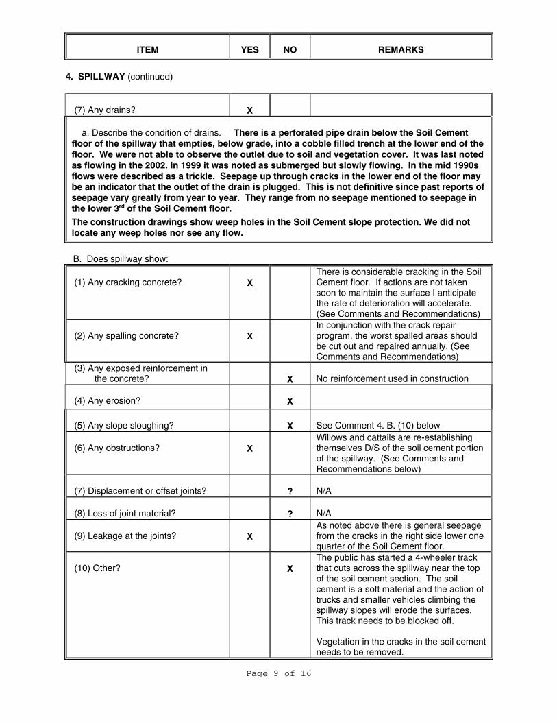
(7) Any drains?
X
a. Describe the condition of drains. There is a perforated pipe drain below the Soil Cement floor of the spillway that empties, below grade, into a cobble filled trench at the lower end of the floor. We were not able to observe the outlet due to soil and vegetation cover. It was last noted as flowing in the 2002. In 1999 it was noted as submerged but slowly flowing. In the mid 1990s flows were described as a trickle. Seepage up through cracks in the lower end of the floor may be an indicator that the outlet of the drain is plugged. This is not definitive since past reports of seepage vary greatly from year to year. They range from no seepage mentioned to seepage in the lower 3rd of the Soil Cement floor.
The construction drawings show weep holes in the Soil Cement slope protection. We did not locate any weep holes nor see any flow.
B. Does spillway show:
(1) Any cracking concrete?
X
There is considerable cracking in the Soil Cement floor. If actions are not taken soon to maintain the surface I anticipate the rate of deterioration will accelerate. (See Comments and Recommendations)
(2) Any spalling concrete?
X
In conjunction with the crack repair program, the worst spalled areas should be cut out and repaired annually. (See Comments and Recommendations)
(3) Any exposed reinforcement in the concrete?
X
No reinforcement used in construction
(4) Any erosion?
X
(5) Any slope sloughing?
X
See Comment 4. B. (10) below
(6) Any obstructions?
X
Willows and cattails are re-establishing themselves D/S of the soil cement portion of the spillway. (See Comments and Recommendations below)
(7) Displacement or offset joints?
?
N/A
(8) Loss of joint material?
?
N/A
(9) Leakage at the joints?
X
As noted above there is general seepage from the cracks in the right side lower one quarter of the Soil Cement floor.
(10) Other?
X
The public has started a 4-wheeler track that cuts across the spillway near the top of the soil cement section. The soil cement is a soft material and the action of trucks and smaller vehicles climbing the spillway slopes will erode the surfaces. This track needs to be blocked off. Vegetation in the cracks in the soil cement needs to be removed.

ITEM YES NO REMARKS
Page 10 of 16
C. No energy dissipaters. D. Has release water:
(1) Eroded the embankment?
X
(2) Undercut the outlet?
X
(3) Eroded the downstream channel?
X
(4) Other?
X
E. Emergency Spillway
(1) Is there an emergency spillway?
X
(If YES, describe)
5. RESERVOIR CONTROL
A) Recent upstream development?
X
B) Recent downstream development?
X
Several new structures in the vicinity of Crane
C) Slides in reservoir area?
X
D) Change in reservoir operation?
X
E) Large impoundment upstream?
X
F) Any debris in the reservoir?
X
Several 3”x 6’ branches washed up on the upstream face
G) Other?
X

ITEM YES NO REMARKS
Page 11 of 16
6. INSTRUMENTATION
A) List type(s) of instrumentation: 1 twin tube stand pipe Piezometer designated DH-4 on
downstream face of the embankment to the right of the outlet.
B) Three additional driven Piezometers, DP-1, DP-2 & DP-3 added in 1998 below DH-4
C) Two shallow piezometers, DH-100 & DH-101 were installed on either side of the outlet conduit in 1995.
B) In good condition?
X
C) Read periodically?
X
Monthly when conditions allow by Dam Tender
D) Is data available?
X
The Dam Tender transmits the data electronically to the FWP Miles City office and to the FWP/DNRC Dam Safety engineer in the DNRC Helena Office
E) Include all data gathered since last report. See attached.
7. DOWNSTREAM CONDITION A. Downstream Land Use.
There is an extensive marshy area immediately below the embankment that is presumed to some degree to be the result of embankment or foundation seepage. The downstream boundary of this area appears to be the Yellowstone Main Canal which traverses the Crane Creek floodplain about ¼ mile below the dam. Between the Yellowstone Main Canal and the Yellowstone River there is relatively flat topography traversed by Highway 16 and the BNSF Railway.
This dam was inspected by: Richard Misplon, PE DNRC Robert Kingery, PE DNRC Sterling Sundheim, CES, DNRC Marvin Cross, CES, DNRC Vickie Eskridge, Dam Tender for FWP Cathy Stewart, Parks Supervisor FWP

Page 12 of 16
Additional Comments and Recommendations. General.
1. Project history: Constructed about 1900. Enlarged in the 1930s. Enlarged 1955. Enlarged 1962. Rehabilitated 1990.
2. Vegetation on the Dam Faces: Overall the grass coverage is good. There are some small areas on the left half of the U/S face that are bald. Crass cutting equipment has torn up the surface in a couple of locations. Near the right abutment on the D/S face there is an area of bare soil and some erosion. These bare and disturbed areas should be dressed and seeded. Generally the best results are obtained by seeding in the fall after September 15 and as soon as the snow goes off in the spring. Woody vegetation is starting to emerge on the U/S face of the dam. On the D/S face there are several isolate shrubs and small trees, the majority are on the right half of the dam. Woody vegetation needs to be removed. At the toe of the right abutment there are a handful of small Cottonwoods and Russian Olives that should be removed. It will not be necessary to remove the larger cottonwoods to the right of the right abutment.
3. Surface irregularities: In 1998 a slump area was noted on the D/S face of the dam 200’-300’ right of the outlet. At the time the opinion was it was a surface phenomenal and not an indication of structural failure. To be on the safe side a set of monitoring pins was installed and has been monitored regularly since then. There has been no sign of significant movement since the initial movement. The latest measurements were made in the spring of 2012. This area will be addressed in more detail in the Gartside Dam 2012 Five Year Report.
4. Traffic Damage: There is a well maintained gravel public access road along the crest of the embankment from the left abutment to a turnaround point near the spillway. Near the spillway an informal gravel access to the reservoir has developed. Boat launching traffic has churned the gravel surface. FWP is maintaining the launch and if the maintenance continues this is posing little risk to the embankment. If maintenance is curtailed launching activity, precipitation and wave action could erode the embankment at this location.
5. Outlet conduit: The outlet was entered this year. Condition of the RCP was good with only very minimal erosion/spalling. Gaps in each joint were measured on the way out. In the past someone had numbered each joint with a grease pen. The numbering started at first joint U/S From the settling basin. The U/S three joints were not numbered and the numbering skipped 19. We used the existing numbering in our notation. (see attachment) For the most part gaps were ½” or less. The 6th joint had a ¼” gap on the right side which may indicate a minor misalignment. Photos looking downstream along the outlet show one section that seems to be slightly out of alignment. The first joint may be an issue. It appears that the gap in the invert is almost 2”. It

Page 13 of 16
was difficult to measure as the water flowing in the invert was deeper here than elsewhere. A gap that large could compromise the seal, allowing seepage into or out of the conduit. It was not possible to determine if this was occurring. Seepage around the concrete stilling basin walls has been a problem in the past. Drain lines were installed in 1998 to deal with it. To seal the joint I propose to use a grout designed for underwater patching such as Thoro Waterplug Hydraulic Cement or similar product from other manufacturers. It’s a simple, relatively easy to install and an inexpensive fix. The biggest obstacles will be dealing with the water leaking past the gate and working within the confines of the 30” conduit. Water flow can be dealt with by using sandbags to route most of the water around the patch area. This work can be done by DNRC with assistance from FWP later this year. It will not be a flexible seal. If the movement that caused the joint to open is still occurring we will see evidence of it in damage to the grout. If movement is still occurring we will need to make further efforts to seal the joint and determine the cause of the movement. Note that the 12v blower was attached to the air vent and appeared to provide good ventilation of the conduit for the entry. Gas meter readings during the entry were all good.
6. Gate and Gate Operator: Since 2010 the gate has been difficult to close
completely. Several inches from complete closure the operator will bind up. After applying moderate pressure to the gate operator wheel and letting it sit, after a few minutes there is a “pop”, the pressure is released and the gate closure can continue. This may happen several times during complete closure operations. During this visit we opened the gate to 14” then closed it again. It seized and popped once shortly before closure. We were able to close the gate within 2 treads of the stop nut. The gate continued to leak about 3 gpm. In 2011 the dam tender had rigged up steel and wood bracing to keep the operator and mounting plate from squirming around and pushing away from the vault wall. The forces developed during closing had warped the original operator mounting plate. A new heavier duty plate which will be mounted with four studs rather than the original two has been fabricated by FWP maintenance staff but not yet installed. The original plate has been better secured to the vault wall by FWP crews and the bracing has been removed. The conduit was entered this year and an inspection of the gate made. As noted above, the gate may not have been entirely closed and an estimated 3 gpm is leaking past the seals. Almost all of this volume is coming from a large stream of water spraying from the left D/S corner of the gate. There were several small streams around the perimeter of the gate. A piece of what appears to be the neck of a plastic beverage bottle was stuck between the gate and the frame at the center D/S of the gate. We did not have any tools to remove it. There was no significant leakage adjacent to this debris.

Page 14 of 16
The gate and frame had minor surface corrosion. With the spraying water close observation was difficult but the gate and frame seemed to be in good condition and no obvious clues to what is causing the binding were found. Assuming the new operator mounting plate does not fix the gate closure problem the DNRC will make recommendations this winter on other options to fix the problem.
7. Spillway Soil Cement: The unreinforced soil cement surface of the spillway
is subject to cracking and spalling. This is common for soil cement construction. Moisture, frost and vegetation will continue to cause deterioration in the surface. The soil cement surface will fail without maintenance. As recommended in the past, an annual repair program should be set up to cut out and repair the worst of the cracks & spalls. In addition at this time there are enough deteriorated areas I recommend that a one-time project/contract be set up to repair cracks and spalling to bring the surface back to good condition. In making past repairs the general opinion was the soil cement was not strong enough to make saw cutting the edges of the repairs effective. It was felt that removing the soil cement around the crack or spall until competent material was reached and patching the resulting irregular area would be most effective. It may be worth revisiting that. Some patches were made using the saw-cut method and from what we saw at the inspection it seemed the saw-cut patches were holding up better than the irregular patches. Vegetation sprouting up in the cracks should be removed. Failure to act will hasten the deterioration of the of the spillway floor.
8. Spillway Vegetation: Along the banks of the spillway both upstream and
downstream of the soil cement portion of the spillway there are several Russian Olives in the flow path. These need to be removed. In 2010 the spillway below the soil cement floor was completely cleared of a heavy growth of cotton wood, willow and other trees and brush. The vegetation has made a significant comeback, especially the willows. At a minimum the willows should be cleared again either by herbicides or by mechanical means with a follow up of herbicides to prevent the re-growth from becoming firmly established.
9. Spillway Vegetation Cattails and a few willows are starting to crowd in from the banks upstream of the Soil Cement. The willows need to be removed. Whenever dry conditions allow, removal of the cattails is desirable.

Page 15 of 16
Maintenance Recommendations
1. Work with DNRC to install the replacement operator mounting plate. Replacement plate to be fastened to the vault wall with 4 mounting bolts rather than the original 2 bolts.
2. While the operator mounting plate is being replaced remove the rubber boot
covering the threaded rod between the top of the oil filled pipe and the operator. Check to see if there is an obstruction that would cause the stop nut, located between the operator and the top of the oil filled pipe, to bind up during operation or if there are other issues that might cause binding. The stop nut was installed as a safety measure to keep from opening the gate too far as happened in 1995. If binding is suspected the stop nut could be removed. If the stop nut is removed anyone operating the gate will need to carefully check that that they do not open the gate too far. If the stop nut is removed a placard should be installed next to the operator with a warning of the maximum distance the gate may be safely opened.
3. Keep the DNRC informed of operational problems with the slide gate.
4. The DNRC will coordinate with FWP to develop a plan to determine the cause of
the problem and implement a solution.
5. Continue to lubricate and maintain the operator on a regular basis.
6. Post a copy of the Emergency Plan in the vault.
7. DNRC will recommend a method to repair the possible open joint in the outlet conduit. The DNRC will coordinate with the FWP for an onsite visit to make the repair.
8. Repair cracks and spalling on the spillway soil cement floor. This has been and
will be an ongoing maintenance issue. A scheduled and budgeted annual program would allow you to keep up with the repair work and prevent it from becoming over whelming. Consider a one-time project/contract to do enough repairs to bring the surface back to good condition. DNRC can provide you with specifications and assistance in the field.
9. Continue to maintain the surface of the informal launch area near the spillway.
10. Block the 4-wheeler trail across the spillway.
11. Use herbicide or physically remove the vegetation growing in the cracks in the soil cement spillway floor.
12. The next time excavation equipment is on site for other operations it would be a
good opportunity to dig out the under slab drain outlet, clean out the drain if

Page 16 of 16
plugged and replace trench fill in front of outlet with clean rock to ensure the drain is functioning optimally. DNRC has drawings and photos of the original installation.
13. Use herbicide or physical means and herbicides to control the willow re-growth both downstream and upstream of the soil cement portion of the spillway. If dry conditions prevail and there is an opportunity to do it efficiently, removal of cattails upstream and downstream of the soil cement portion of the spillway would be desirable.
14. Remove Russian Olives and any other trees or woody brush within the flow line
of the spillway.
15. Remove small Cottonwoods and Russian Olives at the toe of the dam adjacent to the RT abutment. The large Cottonwoods to the RT of the abutment can remain.
16. Remove floating debris from the reservoir.
17. Continue efforts to remove emergent woody plants from both U/S & D/S dam faces.
18. Reseed areas on the dam faces that lack grass cover. Repair and reseed areas
damaged by grass mowing operations.
19. Remove the small Russian Olive below the stilling basin that is encroaching on the outlet channel. Continue efforts to control cattails below the stilling basin.

Gartside Dam
Photo Appendix June 26, 2012
`
U/S face from LT Abutment, Note emergent woody
vegetation and drift wood on face.
U/S face of dam from near gate operator vault looking
SW
U/S face dam from center looking west. Note
emergent woody vegetation and good condition of the
riprap. The informal boat launch area is in the distance
near the spillway.
U/S face dam from center looking NE. Note good
condition of the riprap.
1 of 6

Gartside Dam
Photo Appendix June 26, 2012
Riprap on U/S face near RT abutment. Condition looks
good. Note some emergent woody vegetation.
Informal boat access near RT abutment. Note damage
to U/S face from "spinout" while launching/retrieving.
4-wheeler trail across U/S end of soil cement portion
of spillway. To protect the sides of the spillway this
needs to be eliminated.
U/S approach to soil cement portion of spillway. Note
encroaching trees in flow path on far bank and the
spread of cattails.
2 of 6

Gartside Dam
Photo Appendix June 26, 2012
Looking D/S along the soil cement portion of the
spillway from the U/S end of the soil Cement
Seepage and vegetation growing out of the cracks in
the soil cement at the D/S end of the spillway. Note
emergent willows on far bank
Robust re-growth of willows and cattails below the soil
cement portion of the spillway.
Robust re-growth of willows and cattails below the soil
cement portion of the spillway. Willows need to be
removed.
3 of 6

Gartside Dam
Photo Appendix June 26, 2012
RT abutment. Remove small Cottonwood and Russian
Olive trees from toe of dam. Large Cottonwood trees
to the RT of the abutment may remain.
Woody vegetation becoming established on the D/S
face of the dam near the RT abutment.
D/S face of dam near center looking to the NE Coal seam seep D/S of LT abutment.
4 of 6

Gartside Dam
Photo Appendix June 26, 2012
another view of coal seam seep D/S of LT abutment. Outlet Conduit/Stilling basin joint. Note 3-5 gpm flow with
gate as closed as we could manage(~ 1/2" from stop nut).
Note also that the Conduit is slightly more recessed into the
stilling basin joint at the top than at the invert.
Leak in gate seal D/S LT corner of gate. Only a few
other minor leaks were evident.
Remnants of a plastic bottle jammed between the gate
and the frame. We were unable to remove it without
tools
5 of 6

Gartside Dam
Photo Appendix June 26, 2012
View from interior of Outlet Conduit. View from interior of Outlet Conduit. Note jog in
conduit and area of wider water surface near outlet.
Outlet Conduit exit. Note wider water surface near the
Exit indicating deeper water and a change in the slope
of the conduit
Inspector Rich Misplon in the Conduit. Note lots of
lights and very wet.
6 of 6

Gartside Seepage Monitoring
Date DH-4A DH-4B DH-100 DH-101 DP-1 DP-2 DP-3
Distance from shelter to
water's edge (feet) RES_ELEV
Total DepthTop of TOC 1995.56 1995.5 1984.95 1982.78 1988.69 1980.65 1979.562011-04-30 11.80 na 2.80 3.00 10.40 3.20 3.50 45.30 1996.992011-05-31 12.00 na 2.50 2.70 10.20 3.00 3.10 55.00 1995.762012-07-04 11.60 na 2.85 3.30 10.60 3.65 3.10 39.00 1997.302011-08-31 12.30 na 3.52 3.70 10.95 3.65 3.00 68.00 1994.592011-09-30 11.80 na 3.40 3.55 10.70 3.50 3.00 48.00 1996.572011-10-31 11.60 na 2.65 2.80 10.30 3.10 3.10 42.00 1997.482011-11-30 11.80 na 2.70 3.00 10.30 3.20 3.302011-12-31 11.45 na 2.60 2.75 10.00 2.75 3.60 43.80 1997.232012-01-31 11.45 na 2.60 2.75 10.00 2.75 3.60 43.67 1997.232012-02-29 11.70 na 2.60 2.50 10.00 2.90 4.00 49 1996.422012-03-31 11.75 na 2.70 3.00 10.20 3.15 4.00 41.83 1997.52012-04-30 12.10 na 2.75 2.80 10.20 3.10 4.00 50.4 1996.252012-06-02 11.50 na 2.60 3.10 10.40 3.35 3.90 42.08 1997.472012-07-03 11.70 15.60 2.70 3.40 10.65 3.60 3.85 45.08 1997.022012-07-31 11.70 15.55 2.75 3.60 10.50 3.55 3.85 49.67 1996.31

Gartside Seepage Monitoring
Date DH-4A DH-4B DH-100 DH-101 DP-1 DP-2 DP-3
Distance from
shelter to water's edge (feet) RES_ELEV
Top of TOC 1995.56 1995.5 1984.95 1982.78 1988.69 1980.65 1979.56 Dist.2011-04-30 1983.76 1982.15 1979.78 1978.29 1977.45 1976.06 45.30 1996.992011-05-31 1983.56 1982.45 1980.08 1978.49 1977.65 1976.46 55.00 1995.762012-07-04 1983.96 1982.10 1979.48 1978.09 1977.00 1976.46 39.00 1997.302011-08-31 1983.26 1981.43 1979.08 1977.74 1977.00 1976.56 68.00 1994.592011-09-30 1983.76 1981.55 1979.23 1977.99 1977.15 1976.56 48.00 1996.572011-10-31 1983.96 1982.30 1979.98 1978.39 1977.55 1976.46 42.00 1997.482011-11-30 1983.76 1982.25 1979.78 1978.39 1977.45 1976.262011-12-31 1984.11 1982.35 1980.03 1978.69 1977.90 1975.96 43.80 1997.232012-01-31 1984.11 1982.35 1980.03 1978.69 1977.90 1975.96 43.80 1997.232012-02-29 1983.86 1982.35 1980.28 1978.69 1977.75 1975.56 49 1996.422012-03-31 1983.81 1982.25 1979.78 1978.49 1977.50 1975.56 41.83 1997.52012-04-30 1983.46 1982.20 1979.98 1978.49 1977.55 1975.56 50.4 1996.252012-06-02 1984.06 1982.35 1979.68 1978.29 1977.30 1975.66 42.08 1997.472012-07-03 1983.86 1979.90 1982.25 1979.38 1978.04 1977.05 1975.71 45.08 1997.022012-07-31 1983.86 1979.95 1982.20 1979.18 1978.19 1977.10 1975.71 49.67 1996.31


1980
1990ez
omet
er W
ater
Ele
vatio
n
Gartside - DH-4A vs Reservoir
19701980 1990 2000
Pi
Reservoir Elevation
2011 2012

1980
1990
ezom
eter
Wat
er E
leva
tion
Gartside - DH-4B vs Reservoir
19701980 1990 2000
Pi
Reservoir Elevation
2012
No data since 2006

1980
1990
ezom
eter
Wat
er E
leva
tion
Gartside - DP-1 vs Reservoir
19701980 1990 2000
Pi
Reservoir Elevation
2011 2012

1970
1980
iezo
met
er W
ater
Ele
vatio
nGartside - DP-2 vs Reservoir
19601980 1990 2000
Pi
Reservoir Elevation
2011 2012

1970
1980
ezom
eter
Wa
ter E
leva
tion
Gartside - DP-3 vs Reservoir
19601980 1990 2000
Pi
Reservoir Elevation
2011 2012

1980
1990
ezom
eter
Wat
er E
leva
tion
Gartside - DH-100 vs Reservoir
19701980 1990 2000
Pi
Reservoir Elevation
2011 2012

1980
1990
ezom
eter
Wat
er E
leva
tion
Gartside - DH-101 vs Reservoir
19701980 1990 2000
Pi
Reservoir Elevation
2011 2012

Joint Number
Invert Crown Other Notes:
Conduit Outlet
1 1‐7/8" 1/2"
Water flow and depth of water at this joint made invert measurement difficult, measurement made at water line. Joint full of green organic material & debris.
2 3/8" 1/4" Water flow made invert measurement difficult3 1/4" 5/16" Water flow made Invert measurement difficult4 3/8" 1/4"5 5/16" 9/16"6 <1/4" < 1/4" rt 1/4" Gap on right side of joint7 tight tight8 3/8" 1/4"9 < 1/4" < 1/4"10 tight tight11 1/2" 1/2"12 3/8" 1/2"13 3/8" 3/8"14 9/16" < 1/4"15 tight 7/16"16 tight < 1/4"17 < 1/4" tight18 tight 1/2"
Joint numbers went directly from #18 to #20 skipping # 1920 < 1/4" 1/4"21 tight tight22 tight < 1/4"23 tight 1/4"24 1/4" < 1/4" No number on conduit wall, some spalling25 < 1/4" 1/4" No number on conduit wall26 1/2" 1/4" No number on conduit wall
Inlet Structure
Gartside Outlet ConduitJoint Gap Measurements
26-Jun-12Misplon & Kingery
Kingery did measurements, Misplon took notes. Joints had been numbered previously with a grease pen on the upper portions of the conduit. The #1 joint was the first joint U/S from the Conduit outlet. The joint U/S of #18 was numbered #20, skipping #19. The U/S most 3 joints were not numbered. in a moderate search of the records I was unable to find notes corresponding to the joint numbers. The gate was leaking about 3 gpm. Water was backed up deeper over joint #1 which had a gap of about 2" in the invert. It's not obvious what is at work here. The gap and the deeper water at the joint would indicate either the joint has subsided or that the outlet end of the conduit has risen in respect to the conduit's ruling grade. If the conduit has settled at this joint you would expect there to be a similar gap in the crown of the adjacent joints but the measurements don’t show that. The outlet end of the conduit is slightly more recessed from the face of the stilling basin structure at the top of the joint than the bottom. This could indicate a settling of the first joint but as noted above without gaps in the joints of the crown of the conduit upstream of the first joint this seems unlikely. The entire conduit would have had to subside uniformly. It could indicate the Stilling Basin has risen thereby raising the end of the outlet conduit and opening the first joint but that does not seem likely either. Generally if it was going to move you would expect ito subside.