Walking Dead - Betson Enterprises · Walking Dead - Betson Enterprises ... 1

GarTech LUIS User’s Guide
Copyright GarTech Enterprises Inc. 2008

© 2008 GarTech Enterprises, Inc. Prepared by Logos Ltd. Version 08DEC08
Table of Contents
Introduction 1LUIS Setup 3 Ordering Hardware 4 How To Setup the LUIS 5 Setting Up a Standard LUIS 6 Setting Up a CAN Card Connection 10 Setting Up an Ethernet Connection 14 Changing the Sidecar 18 Adding Child Control Modules 20 Downloading New Firmware 24 ROM Booting 26
The LUIS Graphical User Interface 29 Menu Bar 31 Toolbar 33 Waveform Gauges 34 Lamp Indicators 35 Throttle Ratiometric Dial 37 I/O Controls 38 Switches 39 Ratiometrics 40 Resistives 41 Closed Loop Controls 42 Other Windows and Dialog Boxes 44
Configuring the LUIS GUI 49 The Component Configuration Window 50 The Menu Bar 51 The Toolbar 52 Panels 54 Creating Interpolation Tables 55 Creating an Interpolation Table 56 Importing an Interpolation Table 58 Deleting an Interpolation Table 60 Configuring Waveform Gauges 62 Configuring All Other Controls 70 Configuration Options 74

© 2008 GarTech Enterprises, Inc. Prepared by Logos Ltd. Version 08DEC08
Table of Contents, Continued
The FMET Graphical Interface 77 How To Connect an FMET Box 78 The FMET Workflow 79 The FMET Interface 80 Menu 82 Toolbar 83 Fault Switches 84 Apply Fault Switches 85 Status Indicators 86 I/O Controls 88
Appendix 97 Waveforms 98 RS232 Channel Numbering 99 DAC Specific’s 101 Address Switch 102 Table Calibration 103 Troubleshooting 105 Connectors and Pinout 110 CAN Protocol 119 Multi-Parent Setup 128

Page 1
© 2008 GarTech Enterprises, Inc. Prepared by Logos Ltd. Version 08DEC08
The Load Box User Interface System
Introduction
Introduction The Load Box User Interface System, LUIS, is an engine simulator used to
facilitate bench top engine control system hardware and software testing.
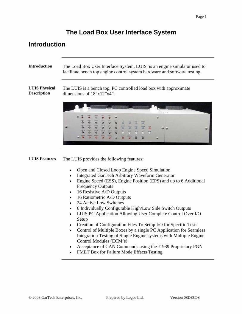
LUIS Physical Description
The LUIS is a bench top, PC controlled load box with approximate dimensions of 18”x12”x4”.
LUIS Features The LUIS provides the following features:
• Open and Closed Loop Engine Speed Simulation • Integrated GarTech Arbitrary Waveform Generator • Engine Speed (ESS), Engine Position (EPS) and up to 6 Additional
Frequency Outputs • 16 Resistive A/D Outputs • 16 Ratiometric A/D Outputs • 24 Active Low Switches • 6 Individually Configurable High/Low Side Switch Outputs • LUIS PC Application Allowing User Complete Control Over I/O
Setup • Creation of Configuration Files To Setup I/O for Specific Tests • Control of Multiple Boxes by a single PC Application for Seamless
Integration Testing of Single Engine systems with Multiple Engine Control Modules (ECM’s)
• Acceptance of CAN Commands using the J1939 Proprietary PGN • FMET Box for Failure Mode Effects Testing

Page 2
© 2008 GarTech Enterprises, Inc. Prepared by Logos Ltd. Version 08DEC08
This page left intentionally blank

Page 3
© 2008 GarTech Enterprises, Inc. Prepared by Logos Ltd. Version 08DEC08
Chapter 1 - LUIS Setup
Overview
LUIS Hardware
The LUIS has a main, parent, control module that can be connected to the PC via a CAN card or an Ethernet connection. Up to 2 additional child control modules can be added for testing a single engine system with multiple ECM’s. A sidecar is also available allowing for injector loads and application specific high current loads. This diagram illustrates the back panel of the standard LUIS.
In This Section This table outlines the topics covered in this section.
Topic See Page
Ordering Hardware 4
How To Setup the LUIS 5

Page 4
© 2008 GarTech Enterprises, Inc. Prepared by Logos Ltd. Version 08DEC08
Section 1 - Ordering Hardware
Ordering Hardware
Gartech Contact Information
All hardware can be ordered from GarTech Enterprises, Inc.
Gartech Enterprises, Inc. 3037 W. State Road 256 Austin, IN 47102 812-794-4796 www.gartechenterprises.com [email protected]
GarTech Part Numbers
This table gives the part number and descriptions for the LUIS hardware.
Part Number Description G00391-00 LUIS PC Controller with 10” LC Monitor,
Keyboard, Mouse and CAN Card G00392-04 LUIS Main (Parent) Control Module with
LED front panel G00726-10 LUIS Sidecar with Injector Loads and LED’s G00393-02 LUIS Child Control Module (for multiple
ECM systems) with sidecar G012191-00 FMET Box
GarTech Wiring Harnesses
A complete listing of Wiring Harnesses available can be found on the GarTech website, www.gartechenterprises.com.

Page 5
© 2008 GarTech Enterprises, Inc. Prepared by Logos Ltd. Version 08DEC08
Section 2 - How To Setup the LUIS
Overview
Introduction The setup of the LUIS software is completed by downloading the software
and following the installation wizard. The setup of the LUIS hardware depends on the PC connection as well as the optional equipment added to the standard control module.
In This Section This table outlines the topics found in this section.
Topic See Page
Setting Up a Standard LUIS 5
Setting Up a CAN Card Connection 6
Setting Up an Ethernet Connection 14
Changing the Sidecar 18
Adding Child Control Modules 20
Downloading New Firmware 24
ROM Booting 26

Page 6
© 2008 GarTech Enterprises, Inc. Prepared by Logos Ltd. Version 08DEC08
Setting Up a Standard LUIS
Setting Up a Standard LUIS
Introduction The LUIS can communicate with the PC through a CAN Card or Ethernet
connection. However, the basic hardware setup is the same.
Hardware Needed
To setup the LUIS, the following hardware is required.
• Standard LUIS • PC • Control Module • Wiring Harness • Control Module Power Connector • DC Power Cable • DC Power Supply • AC Power Cable • J1939 Cable
Setting Up the Hardware
This table outlines the physical connections required to setup the hardware to run a standard LUIS.
Step Action
1 Using the J1939 cable, connect the Public J1939 port on the back of the LUIS to the right hand Public J1939 port on the back of the Sidecar.
3 Install the Control Module on the pegs located on the top of the LUIS.
4 Using the appropriate Wiring Harness, connect the Control Module to the LUIS using the ports on top of the box as well as the Injector Connector on the back of the Sidecar.
5 Using the Control Module Power Connector, connect the Control Module to the Unswitched Power Out port on the back of the LUIS.
Continued on next page

Page 7
© 2008 GarTech Enterprises, Inc. Prepared by Logos Ltd. Version 08DEC08
Setting Up a Standard LUIS, Continued
J1939 Cable Connections
This picture illustrates the J1939 Cable connections between the LUIS and the Sidecar.
Control Module Connections
This picture illustrates the installed Control Module with the Wiring Harness and Power Connector.
Continued on next page
J1939 Cable
Wiring Harness
Control Module Power Connector
Injector Connector

Page 8
© 2008 GarTech Enterprises, Inc. Prepared by Logos Ltd. Version 08DEC08
Setting Up a Standard LUIS, Continued
Setting Up the Hardware, Continued
This table continues to outline the physical connections required to setup the hardware to run a standard LUIS.
Step Action
6 Using the DC Power Cable, connect the LUIS to the DC Power Supply using the Unswitched Power In ports on the back of the LUIS.
7 Using the AC Power Cable, plug the LUIS in.
8 To complete the connection to the PC, please go to the appropriate setup section for CAN Card or Ethernet.
Continued on next page

Page 9
© 2008 GarTech Enterprises, Inc. Prepared by Logos Ltd. Version 08DEC08
Setting Up a Standard LUIS, Continued
DC Power Connections
This picture illustrates the DC Power connection between the LUIS and the DC power supply.
AC Power Supply
This picture illustrates the AC power connection.
AC Power Connection

Page 10
© 2008 GarTech Enterprises, Inc. Prepared by Logos Ltd. Version 08DEC08
Setting Up a CAN Card Connection
Setting Up a CAN Card Connection
Introduction The LUIS can communicate with a PC via a CAN Card.
Hardware Required
To connect the LUIS with a CAN card, the following hardware is required.
• CAN Card or other Peak Adapter • CAN Card Cable with 120 ohm terminating resistor across CAN High
and CAN Low at both ends
Setting Up a CAN Card Connection
This table outlines the steps required to setup the LUIS hardware and software to run via a CAN Card connection.
Step Action
1 After completing the setup for a standard LUIS, use the CAN Cable to connect the PC CAN Card to the left hand Public J1939 port on the Sidecar.
Note: The CAN Cable must have a 120 ohm terminating resistor across CAN High and CAN Low at both ends.
2 Power up both the PC and LUIS.
3 Open the Windows Control Panel from the Start button.
4 DoubleClick the CAN Hardware icon to view the CAN settings. Verify that the correct CAN device type is selected. Once the device type is correct, close
the dialog box as well as the Control Panel.
5 Start the LUIS software.
6 From the Hardware menu, Select the Select Adapter option. The Peak CAN option should be selected. If it is not selected, from the adapter options Select Peak CAN.
Note: If changing the adapter type a message dialog box displays indicating that the LUIS software must be restarted for the change to take effect. Click <Yes> to restart. The user must restart LUIS.
Continued on next page

Page 11
© 2008 GarTech Enterprises, Inc. Prepared by Logos Ltd. Version 08DEC08
Setting Up a CAN Card Connection, Continued
CAN Card Connection
This picture illustrates the CAN Cable connection between the PC and the LUIS.
CAN Hardware Options
This is an example of the CAN Hardware options available from the Windows Control Panel.
Continued on next page
CAN Cable

Page 12
© 2008 GarTech Enterprises, Inc. Prepared by Logos Ltd. Version 08DEC08
Setting Up a CAN Card Connection, Continued
Setting Up a CAN Card Connection, Continued
This table continues to outline the steps required to setup the LUIS hardware and software to run via a CAN Card connection.
Step Action
7 From the Hardware menu, Select the Peak Adapter option. From the Peak Adapter options, Select Set Net Name.
Result: The Net Name dialog box displays.
8 The Current Net Name field displays the net name currently in use. If the net name is not correct, Type the correct name in the field and Click <OK>.
Note: If changing the net name a message box displays indicating that the LUIS software must be restarted for the change to take effect. Click <Yes> to restart.
9 The LUIS hardware and software is installed and ready to run communicating through the CAN Card connection.
Continued on next page

Page 13
© 2008 GarTech Enterprises, Inc. Prepared by Logos Ltd. Version 08DEC08
Setting Up a CAN Card Connection, Continued
Net Name Dialog Box
This is an example of the Net Name dialog box.

Page 14
© 2008 GarTech Enterprises, Inc. Prepared by Logos Ltd. Version 08DEC08
Setting Up an Ethernet Connection
Setting Up an Ethernet Connection
Introduction The LUIS can communicate with the PC through an Ethernet connection.
Hardware Needed
To connect the LUIS through the Ethernet, the following hardware is required.
• Optional LUIS Ethernet Card • Crossover Ethernet Cable or Hub and Ethernet Cables
Setting Up an Ethernet Connection
This table outlines the steps for setting up the LUIS hardware and software to run via an Ethernet connection.
Step Action
1 After completing the setup for a standard LUIS, use the appropriate Ethernet cable to connect the PC to the LUIS.
Note: To connect directly, a crossover cable must be used.
2 Power up both the PC and LUIS.
3 Start the LUIS software.
4 From the Hardware menu, Select the Select Adapter option. From the Adapter options, Select Ethernet.
Result: The message dialog box displays indicating that the LUIS software must be restarted for the change to take effect. Click <Yes> to restart.
5 Once LUIS has restarted, from the Hardware menu, Select the Ehternet option. From the Ethernet options, Select Configure.
Result: The Ethernet Configuration window displays.
6 In the F/W Version field, the current firmware version displays. Note: This firmware version applies only to the TCP/IP add-on card. It is not the same as the LUIS firmware
Continued on next page

Page 15
© 2008 GarTech Enterprises, Inc. Prepared by Logos Ltd. Version 08DEC08
Setting Up an Ethernet Connection, Continued
Ethernet Connection
This picture illustrates the Ethernet connection between the PC and the LUIS.
Ethernet Configuration Window
This graphic is an example of the Ethernet Configuration window.
Continued on next page

Page 16
© 2008 GarTech Enterprises, Inc. Prepared by Logos Ltd. Version 08DEC08
Setting Up an Ethernet Connection, Continued
Setting Up an Ethernet Connection, Continued
This table continues to outline the steps for setting up the LUIS hardware and software to run via an Ethernet connection.
Step Action
7 In the Search for Devices panel, Click the <Search> button.
Result: The MACID Addresses for all local devices display in the Detected Devices field.
Note: A direct IP Search can be completed to find an IP address outside the local devices by Selecting the Direct IP Search checkbox, entering the IP Address and Clicking <Search>.
8 Select the MACID Address for the Ethernet card in the LUIS box from the list.
Note: The Ethernet card should be labeled with its MACID Address.
9 The fields on the window display the information for the selected Ethernet card.
10 Make any changes required.
Note: Changes cannot be made if the card is in DHCP mode.
11 Once the Ethernet settings are correct, Click the <Set> button.
12 To close the window, Click the <Exit> button.
13 To begin communicating, from the Hardware menu, Select Ethernet and then the Connect/Disconnect option.
Result: The LUIS hardware and software is installed and is communicating through the Ethernet connection.
Continued on next page

Page 17
© 2008 GarTech Enterprises, Inc. Prepared by Logos Ltd. Version 08DEC08
Setting Up an Ethernet Connection, Continued
Ethernet Configuration Window
This graphic is an example of the Ethernet Configuration window.

Page 18
© 2008 GarTech Enterprises, Inc. Prepared by Logos Ltd. Version 08DEC08
Changing a Sidecar
Changing a Sidecar
Introduction Sidecars can be added to the parent LUIS to allow for injector loads and
application specific high current loads. Different Sidecars are needed depending on the loads required.
Changing a Sidecar
This table outlines the steps for changing a Sidecar.
Step Action
1 Power down the LUIS unit.
2 Disconnect all the cables connected to the back of the Sidecar.
3 Unscrew the two thumbscrews holding the Sidecar to the Load Box.
Note: There is one screw on the front of the unit and one on the back.
4 Carefully pull the sidecar away from the Load Box.
5 Disconnect the internal cable between the Sidecar and the Load Box.
6 Connect the internal cable between the new Sidecar and the Load Box.
7 Carefully push the Sidecar to the load box.
8 Screw in the two thumbscrews to attach the Sidecar to the Load Box.
9 Connect all the cables to the back of the new Sidecar.
10 Power up the LUIS.
11 The new loads can now be added to the configuration file in the LUIS GUI.
Continued on next page

Page 19
© 2008 GarTech Enterprises, Inc. Prepared by Logos Ltd. Version 08DEC08
Changing a Sidecar, Continued
Sidecar Assembly/Disassembly
This picture illustrates the Sidecar detached from the Load Box.
Internal Connection
This picture illustrates the internal connection between the Sidecar and the Load Box.

Page 20
© 2008 GarTech Enterprises, Inc. Prepared by Logos Ltd. Version 08DEC08
Adding Child Modules
Adding Child Modules
Introduction Up to two child modules can be added to the LUIS for testing a single engine
system with multiple ECM’s.
Hardware Required
This following hardware is required when adding a child module.
• ECM • Child Load Box • Parent/Child J1939 Cables • Parent/Child Private CAN Bus Connector Cables • Parent/Child LUIS Bus Connector Cables • Parent/Child Control Module Power Connector
Adding Child Module
This table outlines the steps for adding child modules to the LUIS. Note: A Parent/Child stack can be ordered directly from GarTech. This unit is shipped already stacked and connected. When this item arrives, this table can be used to ensure that all of the cables are connected as expected and nothing was loosened during shipping.
Step Action
1 Setup the parent module as a standard LUIS.
Note: For more information, see Setting Up a Standard LUIS.
2 Install the Control Module on the pegs located on the top of the Child Load Box.
3 Using the appropriate wiring harness, connect the Control Module to the Child Load Box using the ports on top of the box.
4 Replace the J1939 cable between the Sidecar and Parent Load Box with the Parent/Child J1939 cable. This cable plugs into the right hand Public J1939 port on the Parent Side Car and into the Public J1939 port on each Load Box in the setup.
Continued on next page

Page 21
© 2008 GarTech Enterprises, Inc. Prepared by Logos Ltd. Version 08DEC08
Adding Child Modules, Continued
Public CAN Connections
This picture illustrates the Public J1939 CAN Connections.
Continued on next page

Page 22
© 2008 GarTech Enterprises, Inc. Prepared by Logos Ltd. Version 08DEC08
Adding Child Modules, Continued
Adding Child Module
This table outlines the steps for adding child modules to the LUIS.
Step Action
5 Replace the Control Module Power Connector with the Parent/Child Control Module Power Connector. Connect this cable to the Unswitched Power Out port on the back of each Load Box.
6 Make the private CAN connection by plugging the Parent/Child CAN Connector into the Private J1939 port on each Load Box in the setup.
7 Connect the LUIS Bus by plugging the Parent/Child LUIS Bus Connector into the LUIS Bus port on the back of each Load Box.
Continued on next page

Page 23
© 2008 GarTech Enterprises, Inc. Prepared by Logos Ltd. Version 08DEC08
Adding Child Modules, Continued
Control Module Power Connections
This picture illustrates the Control Module Power Connections.
Private CAN Connections
This picture illustrates the Private CAN Connections.
LUIS Bus Connections
This picture illustrates the LUIS Bus connections.

Page 24
© 2008 GarTech Enterprises, Inc. Prepared by Logos Ltd. Version 08DEC08
Downloading New Firmware
Downloading New Firmware
Introduction Firmware is an instruction set stored in the ROM. Parent and Child boxes
have same firmware. The Wavemaker and FMET Box have different Firmware.
Downloading Firmware
This table outlines the steps for downloading firmware.
Step Action
1 Before downloading firmware, ensure that both the VBatt and Keyswitch are off and that Engine Speed is set to 0.
2 Close any datalink tools running on the PC. 3 From the Hardware menu, Select the Download Firmware
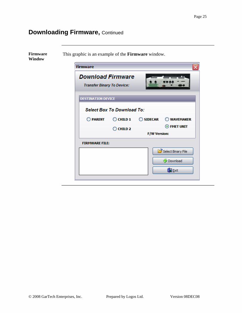
option. Result: The Firmware window displays.
4 In the Destination Device section, Select the hardware to which the firmware will be downloaded.
5 Click the <Select Binary File> button. On the Open dialog box, Browse and Select the correct firmware file, and Click <Open>. Note: To avoid errors, the firmware to download should be resident on the local machine rather than on a network drive.
6 Once the firmware file has been selected, Click the <Download> button. Troubleshooting: If the download fails to complete or errors occur, the LUIS must be ROM booted to be able to continue. See ROM Booting in this section. Result: The firmware is downloaded to the selected device. As the download occurs, messages display in the Firmware File field.
7 Once the download is complete, Click the <Exit> button to close the dialog box. Note: If new firmware was downloaded to the Wavemaker, the power on the LUIS box must be cycled before the download will be complete.
Continued on next page
Page 25
© 2008 GarTech Enterprises, Inc. Prepared by Logos Ltd. Version 08DEC08
Downloading Firmware, Continued
Firmware Window
This graphic is an example of the Firmware window.

Page 26
© 2008 GarTech Enterprises, Inc. Prepared by Logos Ltd. Version 08DEC08
ROM Booting
ROM Booting
Introduction ROM Booting is a troubleshooting process used to reset the hardware after a
failed download or if communications stop between the LUIS and the PC.
ROM Booting This table outlines the steps for ROM Booting.
Step Action
1 Shut down the LUIS box.
2 In the LUIS software, from the Hardware menu Select the Download Firmware option.
Result: The Firmware dialog box displays.
3 Click the <Select Binary File> button. On the Open dialog box, find and select the appropriate firmware file.
Note: The firmware should be resident on the PC not on a network drive.
4 Click the <Download> button.
Result: The “Do Not Turn Unit Off” message displays.
5 A series of messages will display. When the “Resetting Loadbox” message displays, turn the LUIS box power on.
Note: The LUIS box must be powered on within about 2 seconds of the message or the ROM Boot will fail. If this happens, try again.
6 The firmware will be downloaded to all devices simultaneously except the Wavemaker. When the download is complete the “Firmware Update Complete” message displays.
7 Communication should now be restored between the PC and the LUIS Box.
8 Since the Wavemaker uses different firmware, it must be downloaded via the standard Download Firmware procedure earlier in this section. Until this download is complete, the firmware version will display as 99.99.
Continued on next page

Page 27
© 2008 GarTech Enterprises, Inc. Prepared by Logos Ltd. Version 08DEC08
ROM Booting, Continued
Firmware Dialog Box
This graphic illustrates the “Resetting Loadbox” message on the Firmware dialog box.

Page 28
© 2008 GarTech Enterprises, Inc. Prepared by Logos Ltd. Version 08DEC08
Notes

Page 29
© 2008 GarTech Enterprises, Inc. Prepared by Logos Ltd. Version 08DEC08
Chapter 2 – The LUIS Graphical User Interface
Overview
Introduction The LUIS comes with a graphical user interface for controlling all outputs as
well as for setting up closed loop controls. The LUIS GUI is made up of a menu system, toolbar, waveform gauges, lamp indicators, throttle dial, I/O controls, and closed loop controls.
LUIS GUI Basic Environment
This diagram and table describe the basic LUIS GUI environment.
Description
1 Menu Bar
2 Toolbar
3 Waveform Gauges
4 Lamp Indicators
5 Throttle Ratiometric Dial
6 I/O Controls
7 Closed Loop Controls
Continued on next page
1 2
3
4
5
6 7

Page 30
© 2008 GarTech Enterprises, Inc. Prepared by Logos Ltd. Version 08DEC08
Overview, Continued
In This Section This table outlines the topics covered in this section.
Topic See Page
Menu Bar 31
Toolbar 33
Waveform Gauges 34
Lamp Indicators 35
Throttle Ratiometric Dial 37
I/O Controls 38
Closed Loop Controls 42
Other Windows and Dialog Boxes 44

Page 31
© 2008 GarTech Enterprises, Inc. Prepared by Logos Ltd. Version 08DEC08
Section 1 - Menu Bar
Menu Bar
Menus and Options
This table outlines the menus that are available as well as the options available on each menu.
Menu Option Description
File
Open Configuration Opens a saved configuration and applies it to the GUI.
Save Configuration As… Save the current GUI configuration to be opened later.
Exit Exit the LUIS GUI.
Operation
Reset Resets controls to their default positions.
Front Panel Layout Opens the Front Panel Functions dialog box where a replica of the Parent Controller front panel can be customized.
Set Current As Defaults Sets the current settings as the defaults for the configuration.
Configuration Panel Opens the Component Configuration window to setup the GUI.
Data Player Opens the Data Player window to configure the data player.
Hardware
Download Firmware Opens the Firmware dialog box to download new firmware.
Select Adapter Sets the adapter type to Ethernet or Peak CAN.
Page 32
© 2008 GarTech Enterprises, Inc. Prepared by Logos Ltd. Version 08DEC08
Menu Bar, Continued
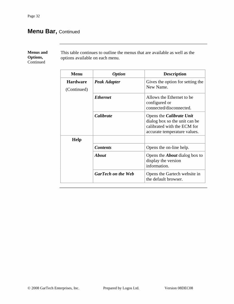
Menus and Options, Continued
This table continues to outline the menus that are available as well as the options available on each menu.
Menu Option Description
Hardware (Continued)
Peak Adapter Gives the option for setting the New Name.
Ethernet Allows the Ethernet to be configured or connected/disconnected.
Calibrate Opens the Calibrate Unit dialog box so the unit can be calibrated with the ECM for accurate temperature values.
Help
Contents Opens the on-line help.
About Opens the About dialog box to display the version information.
GarTech on the Web Opens the Gartech website in the default browser.

Page 33
© 2008 GarTech Enterprises, Inc. Prepared by Logos Ltd. Version 08DEC08
Section 2 – Toolbar
Toolbar
Introduction The toolbar provides quick access to many of the often used menu items.
Toolbar This graphic and table outlines the options available from the toolbar.
Icon Description
Open Configuration
Save Configuration
Reset Switches
Reset Ratiometrics
Reset Gauges
Reset Resistive
Reset Rotary Switches
Download Firmware
Set Net Name
Configure Ethernet
Connect/Disconnect Ethernet
Component Configuration
Front LUIS Panel Layout
Set Current as Default
Reset Communication Interface
Data Player

Page 34
© 2008 GarTech Enterprises, Inc. Prepared by Logos Ltd. Version 08DEC08
Section 3 - Waveform Gauges
Waveform Gauges
Introduction The LUIS has the GarTech Arbitrary Waveform Generator integrated into the
system. The eight waveform gauges provide the ability to monitor and manipulate these waveforms.
Waveform Gauges
The eight waveform gauges are found on two tabs labeled Primary and Secondary. These gauges are setup on the Gauge section of the Component Configuration window. When configuring the gauges the card type, arbitrary or digital, and input and output types must be known. The teeth per revolution, cycles per revolution, ramp rate and PWM heartbeat frequency must also be known. There is also an option to sync waveforms together, however this does nothing to the gauge.
Waveform Gauges Location
This graphic illustrates the waveform gauges and their location on the LUIS main window.

Page 35
© 2008 GarTech Enterprises, Inc. Prepared by Logos Ltd. Version 08DEC08
Section 4 - Lamp Indicators
Lamp Indicators
Introduction There are two rows of lamp indicators on the LUIS GUI. The top row, Load
Box Status, provides feedback on the controllers, sidecar and wavemaker. The second row, Front Panel Lamps, mirrors the lamps on the front of the Parent controller.
Load Box Status
The top row of indicator lamps are labeled Load Box Status. These lamps are illuminated green to indicate that the various hardware pieces are connected and communicating. If a lamp is not illuminated green, that piece of equipment is either disconnected or not communicating.
If Load Box Status lamps indicate that communication has been lost, and communication cannot be restarted by rebooting, follow the Rom Booting procedure earlier in this document to recover communication.
From left to right the indicators show Parent Controller, Child 1, Child 2, Sidecar, and Wavemaker. When the cursor is held over these lamps, a pop-up displays to indicate the current state of the hardware as well as the current firmware version.
Front Panel Lamps
The second row of indicator lamps are labeled Front Panel Lamps. These lamps mirror the lamps on the front of the Parent Controller. This is particularly useful in setups where the controller is not easily in sight. These lamps can be named for easy reference using the Front Panel Layout option on the Hardware menu. When the cursor is held over these lamps, a pop-up displays the name given to that lamp on the Front Panel Layout dialog box.
Continued on next page

Page 36
© 2008 GarTech Enterprises, Inc. Prepared by Logos Ltd. Version 08DEC08
Lamp Indicators, Continued
Indicator Lamps Location
This graphic illustrates the indicator lamps and their location on the LUIS GUI.

Page 37
© 2008 GarTech Enterprises, Inc. Prepared by Logos Ltd. Version 08DEC08
Section 5 - Throttle Ratiometric Dial
Throttle Ratiometric Dial
Introduction On the LUIS GUI there is one ratiometric dial on the front panel.
Throttle Ratiometric Dial
The ratiometric dial on the front panel is automatically configured to be Throttle. This assignment can be changed when configuring the panel. When changing, keep in mind that the Throttle is used for Auto IVS functionality, the IVS switches trigger off of their set switch point and gets its value from this pot knob.
Throttle Ratiometric Dial Location
This graphic illustrates the Throttle Ratiometric Dial and it’s location on the LUIS GUI.

Page 38
© 2008 GarTech Enterprises, Inc. Prepared by Logos Ltd. Version 08DEC08
Section 6 - I/O Controls
I/O Controls
Introduction All the I/O controls are found on seven tabs categorized by control type:
switch, ratiometric, and resistive. All control names, values, units, and scales are setup on the Configuration Panel window.
I/O Controls Location
The different I/O Controls are accessed by pressing the tabs. This diagram illustrates the I/O controls section and its location on the LUIS GUI.
In This Section This table outlines the topics covered in this section.
Topic See Page
Switches 39
Ratiometrics 40
Resistives 41

Page 39
© 2008 GarTech Enterprises, Inc. Prepared by Logos Ltd. Version 08DEC08
Switches
Introduction The first two tabs in the I/O controls section of the GUI provide 32 position
switches and 3 rotary switches. The first switch is defaulted to Keyswitch.
Setting Positions
The two position switches are either in the ON position, which is indicated by the top of the switch being depressed and the switch name being displayed in red, or the OFF position, which is indicated by the bottom of the switch being depressed and the switch name being displayed in black.
OFF ON
The rotary switches are in one of three positions as indicated by the top of the yellow dial as well as displaying the position number in blue.

Page 40
© 2008 GarTech Enterprises, Inc. Prepared by Logos Ltd. Version 08DEC08
Ratiometrics
Introduction The third and fourth tabs in the I/O controls section of the GUI provide
gauges for 16 ratiometric channels.
Setting Values The ratiometrics can be controlled by the dial, the slider, the increment/
decrement arrows, or by typing in the value field.
Ratiometric Units
Ratiometrics can be displayed in millivolts or counts. The units are controlled by the V or C button in the lower right hand corner. The unit displayed on the button is the current unit being used.

Page 41
© 2008 GarTech Enterprises, Inc. Prepared by Logos Ltd. Version 08DEC08
Resistives
Introduction The fifth, sixth, and seventh tabs in the I/O Controls section of the LUIS GUI
provide sliders for 24 resistive channels.
Setting Values The resistive controls can be controlled by the slider or the increment/
decrement arrows.

Page 42
© 2008 GarTech Enterprises, Inc. Prepared by Logos Ltd. Version 08DEC08
Section 7 - Closed Loop Controls
Closed Loop Controls
Introduction The LUIS can be set to run closed loop engine speed control. In this mode the
engine speed signal generated by the load box responds similarly to an actual engine. J1939 public broadcast must be running in the ECM to run in closed loop mode.
Closed Loop Controls
The last tab in the I/O controls section, labeled Speed/Throttle, is the closed loop controls section. Here the engine model and throttle pedal idle validation is setup for closed loop control.
Engine Model In the engine model section, the percent load and gain adjust are set using the
sliders. The loop is set to closed using the Closed/Open switch. The start switch is used to start the closed loop control, and the reset switch set the model back to zero load/rpm.
Continued on next page

Page 43
© 2008 GarTech Enterprises, Inc. Prepared by Logos Ltd. Version 08DEC08
Closed Loop Controls, Continued
Throttle Idle Validation
The throttle idle validation section is used to simulate idle validation. Idle can be set to toggle automatically based on switch points in counts or manually. When the Auto IVS switch is set to On, the On Idle and Off Idle switches turn on and off automatically based on the values entered for the Switch Points in Counts fields. The Switch Point in Counts values apply to the Throttle ratiometric. The On Idle and Off Idle lamps light to indicate the present state. When setting the throttle pedal idle validation manually, click the On Idle and Off Idle switches when required.

Page 44
© 2008 GarTech Enterprises, Inc. Prepared by Logos Ltd. Version 08DEC08
Section 8 - Other Windows and Dialog Boxes
Other Windows and Dialog Boxes
Introduction The LUIS GUI provides other windows and dialog boxes for configuring and
other actions.
Front Panel Window
The Front Panel window is opened from the Operation menu. It displays a picture of the front of the Parent Controller. On this window, the generic labels can be replaced with meaningful names. It can be printed, by pressing the printer icon, and used as a map of the controller.
Configuration The Component Configuration window is used to configure all the I/O
controls on the main screen. This window is available from the Equipment menu.
Continued on next page

Page 45
© 2008 GarTech Enterprises, Inc. Prepared by Logos Ltd. Version 08DEC08
Other Windows and Dialog Boxes, Continued
Firmware Dialog Box
This Firmware dialog box is used to download new firmware to the hardware. This dialog box is available from the Hardware menu.
Net Name Dialog Box
The Net Name dialog box is used to set the net name for the CAN connection. This dialog box is accessed through the Hardware menu.
Ethernet Configuration Dialog Box
The Ethernet Configuration dialog box is used to configure the Ethernet connection. It is accessed through the Hardware menu.
Continued on next page

Page 46
© 2008 GarTech Enterprises, Inc. Prepared by Logos Ltd. Version 08DEC08
Other Windows and Dialog Boxes, Continued
Connect to Hardware Dialog Box
The Connect to Hardware dialog box is used to connect to and disconnect from the Ethernet. This dialog box is accessed through the Hardware menu.
Calibrate Unit Dialog Box
The Calibrate Unit dialog box is used to calibrate hardware to the ECM to ensure accurate temperature readings. This dialog box is accessed through the Hardware menu.
Continued on next page

Page 47
© 2008 GarTech Enterprises, Inc. Prepared by Logos Ltd. Version 08DEC08
Other Windows and Dialog Boxes, Continued
Data Player Dialog Box
The Data Player dialog box is used to load and playback CSV data files. This dialog box is accessed through the Operation menu.

Page 48
© 2008 GarTech Enterprises, Inc. Prepared by Logos Ltd. Version 08DEC08
Notes

Page 49
© 2008 GarTech Enterprises, Inc. Prepared by Logos Ltd. Version 08DEC08
Chapter 3 – Configuring the LUIS GUI
Overview
Introduction Each of the controls on the LUIS GUI can be configured. They can be named
as well as having defaults, units, and minimum/maximum values set. They can be interlocked with other controls, and they can be removed from the display. All configuration takes place on the Component Configuration window.
In This Section This table outlines the topics covered in this chapter.
Topic See Page
The Component Configuration Window 50
Interpolation Tables 55
Configuring Waveform Gauges 62
Configuring All Other Controls 70
Configuration Options 74

Page 50
© 2008 GarTech Enterprises, Inc. Prepared by Logos Ltd. Version 08DEC08
Section 1 – The Component Configuration Window
The Component Configuration Window
Introduction The Component Configuration window is used to configure the LUIS GUI.
The window has its own menu and toolbars unlike those on the main window.
The Component Configuration Window
This graphic and table describe the Component Configuration window.
Description
1 Menu Bar
2 Toolbar
3 Panels
In This Section This table outlines the topics covered in this section.
Topic See Page
The Menu Bar 51
The Toolbar 52
Panels 54
1 2
3

Page 51
© 2008 GarTech Enterprises, Inc. Prepared by Logos Ltd. Version 08DEC08
The Menu Bar
Menus and Options
This table outlines the menus and their options available on the Component Configuration window.
Menu Option Description
File
New Configuration Resets all the fields for a new configuration.
Open Configuration Opens the Open dialog box where an existing configuration can be found and loaded.
Save Configuration As Opens the Save As dialog box so the current configuration can be saved under a new name.
Print Opens the Print Preview window from which the configuration can be printed.
Exit Closes the Component Configuration window.
Component
Switch Displays the switch components in the Panels section of the window.
Pot Knob Displays the pot knob components in the Panels section of the window.
Gauge Displays the gauge components in the Panels section of the window.
Slider Rotary Displays the slider rotary components in the Panels section of the window.

Page 52
© 2008 GarTech Enterprises, Inc. Prepared by Logos Ltd. Version 08DEC08
The Menu Bar, Continued
Menu Option Description
Tools
Apply Apply the configuration to the Main Panel.
Tables Opens the Tables dialog box where tables can be added or modified.
Configuration Options Opens the Options dialog box where Tabs and Engine Model options can be set.
Move Up Moves the selected entry up the list.
Move Down Moves the selected entry down the list.
Page 53
© 2008 GarTech Enterprises, Inc. Prepared by Logos Ltd. Version 08DEC08
The Toolbar
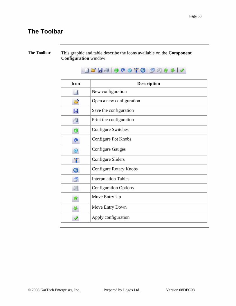
The Toolbar This graphic and table describe the icons available on the Component
Configuration window.
Icon Description
New configuration
Open a new configuration
Save the configuration
Print the configuration
Configure Switches
Configure Pot Knobs
Configure Gauges
Configure Sliders
Configure Rotary Knobs
Interpolation Tables
Configuration Options
Move Entry Up
Move Entry Down
Apply configuration

Page 54
© 2008 GarTech Enterprises, Inc. Prepared by Logos Ltd. Version 08DEC08
Panels
Panels The Panels portion of the Component Configuration window is where the
configuration elements display. The panels for switches, pot knobs, sliders, and rotary are identical except for the number of channels permitted. The panel for gauges has an upper portion identical to the other controls as well as a lower portion for configuring the waveform channels. There is also a panel for managing interpolation tables, and one additional panel for configuration options. The Configuration Options panel allows the user to determine the names and visibility of the tabs on the main window.

Page 55
© 2008 GarTech Enterprises, Inc. Prepared by Logos Ltd. Version 08DEC08
Section 2 –Interpolation Tables
Overview
Introduction Some of the components controlled by the LUIS require an interpolation table
to match the engineering unit that is on the gauge to a counts value. For example 32 PSI is 500 counts, which is a specific voltage that LUIS outputs.
In This Section This table outlines the topics covered in this section.
Topic See Page
Creating an Interpolation Table 56
Importing an Interpolation Table 58
Deleting an Interpolation Table 60

Page 56
© 2008 GarTech Enterprises, Inc. Prepared by Logos Ltd. Version 08DEC08
Creating an Interpolation Table
Introduction Interpolation tables can be created from the Table panel in the Component
Configuration window. The data can be entered manually, or cut and pasted from another application such as Microsoft Excel.
Creating an Interpolation Table
This table outlines the steps for creating an interpolation table.
Step Action
1 From the Operations menu, Select the Configuration Panel option. Result: The Component Configuration window displays.
2 On the Menu Bar, Click the Tables icon . Result: The Table panel displays in the Component Configuration window.
3 If any tables have already been added to the configuration, they display in the Table Name box. The selected table’s contents display in the table on the left hand side of the panel, and its general setup information displays in the fields below the Table Name box.
4 To add a new table directly in the LUIS GUI, Click the <Add Table> button. Result: The Table Name dialog box displays.
5 In the Add Table Name field, Type the name of the new table, and then Click <OK>. Result: The new table name is added to the Table Name box.
6 With the new table name selected, fill in the Min Volts, Max Volts, DAC Multiplier, Table Axis, and Table Notes fields.
7 Add the table data by either Typing it in directly or by Cutting and Pasting from another application.
8 When the table setup is complete, Save the configuration before closing the Table panel. Note: To immediately apply the setup to the front panel, from the File menu Select the Apply Configuration option.
Continued on next page

Page 57
© 2008 GarTech Enterprises, Inc. Prepared by Logos Ltd. Version 08DEC08
Creating an Interpolation Table, Continued
Tables Panel This graphic illustrates the Tables panel in the Component Configuration
window.
Table Name Dialog Box
This graphic illustrates the Table Name dialog box.

Page 58
© 2008 GarTech Enterprises, Inc. Prepared by Logos Ltd. Version 08DEC08
Importing an Interpolation Table
Introduction Interpolation tables can be imported from other calibrations.
Importing an Interpolation Table
This table outlines the steps for importing an interpolation table.
Step Action
1 From the Operations menu, Select the Configuration Panel option. Result: The Component Configuration window displays.
2 On the Menu Bar, Click the Tables icon . Result: The Table panel displays in the Component Configuration window.
3 If any tables have already been added to the configuration, they display in the Table Name box. The selected table’s contents display in the table on the left hand side of the panel, and its general setup information displays in the fields below the Table Name box.
4 To import a table, Click the <Import> button.
Result: The Open dialog box displays.
5 Find the configuration file to import from, and Click <Open>.
Result: The Import Tables dialog box displays.
6 On the Import Tables dialog box, Select the tables to import. Once all the desired tables are selected, Click <Import Selected>.
Result: The table(s) is imported and added to the list of tables.
7 To edit the table, Click on its title to display the value on the left hand side of the panel. Make changes to the table.
8 When the table setup is complete, Save the configuration before closing the Table panel. Note: To immediately apply the setup to the front panel, from the File menu Select the Apply Configuration option.
Continued on next page

Page 59
© 2008 GarTech Enterprises, Inc. Prepared by Logos Ltd. Version 08DEC08
Importing an Interpolation Table, Continued
Tables Panel This graphic illustrates the Tables panel in the Component Configuration
window.
Import Tables Dialog Box
This graphic illustrates the Import Tables dialog box.

Page 60
© 2008 GarTech Enterprises, Inc. Prepared by Logos Ltd. Version 08DEC08
Deleting an Interpolation Table
Deleting an Interpolation Table
This table outlines the steps for deleting an interpolation table.
Step Action
1 From the Operations menu, Select the Configuration Panel option. Result: The Component Configuration window displays.
2 Before a table can be deleted, any references to it by components must be removed. To remove these references, go to the component configuration panels and change the Table field to another table name or select None from the dropdown menu.
3 When all references to the table to be deleted have been removed,
on the Menu Bar, Click the Tables icon . Result: The Table panel displays in the Component Configuration window.
4 If any tables have already been added to the configuration, they display in the Table Name box. The selected table’s contents display in the table on the left hand side of the panel, and its general setup information displays in the fields below the Table Name box.
5 On the Table panel Select the table to delete. Then Click the <Delete> button. Result: The table is deleted and is removed from the table list.
6 When the changes are complete, Save the configuration before closing the Table panel. Note: To immediately apply the setup to the front panel, from the File menu Select the Apply Configuration option.
Continued on next page

Page 61
© 2008 GarTech Enterprises, Inc. Prepared by Logos Ltd. Version 08DEC08
Deleting an Interpolation Table, Continued
Tables Panel This graphic illustrates the Tables panel in the Component Configuration
window.
Table Reference
This graphic illustrates the table references that must be removed before deleting an interpolation table.

Page 62
© 2008 GarTech Enterprises, Inc. Prepared by Logos Ltd. Version 08DEC08
Section 3 – Configuring Waveform Gauges
Configuring Waveform Gauges
Introduction The configuration for the waveform gauges, called gauges on the Component
Configuration window, is different from all the other components as they require configuration of the waveform.
Configuring Waveform Gauges
This table outlines the steps for configuring waveform gauges.
Step Action
1 From the Operations menu, Select the Configuration Panel option. Result: The Component Configuration window displays.
2 On the Menu Bar, Click the Gauges icon . Result: The Gauge panel displays in the Component Configuration window.
3 In the top portion of the Gauges panel, complete the fields for each waveform gauge being used.
Field Description
Name Type in the component name.
Loadbox # For waveform gauges, Select Wavemaker.
Channel Select the channel number from the drop down. This is the physical channel in the Wavemaker. Ensure the channel has the correct card to support the signal.
Visible If selected, the control will display on the main window. If not selected, the control will be hidden on the main window.
Function Select Freq for waveform gauges or DAC to control a voltage signal instead.
Default Sets the default value for the control when the configuration is loaded or the control is reset
Continued on next page
Page 63
© 2008 GarTech Enterprises, Inc. Prepared by Logos Ltd. Version 08DEC08
Configuring Waveform Gauges, Continued
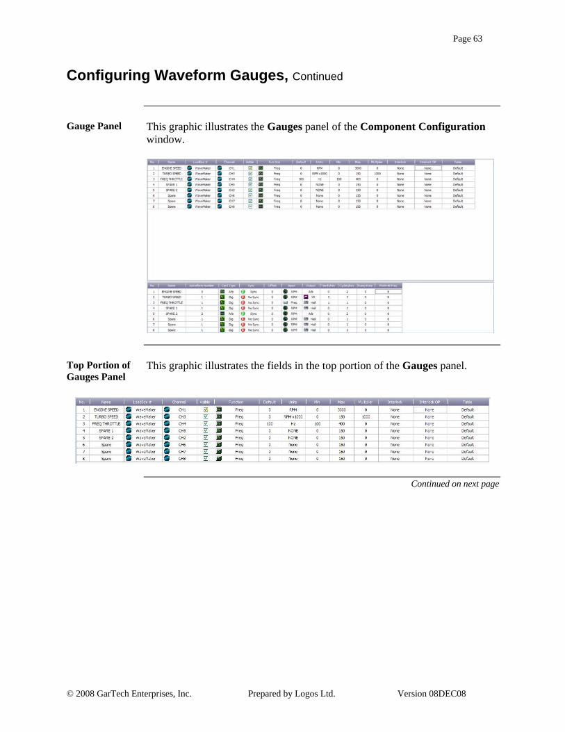
Gauge Panel This graphic illustrates the Gauges panel of the Component Configuration
window.
Top Portion of Gauges Panel
This graphic illustrates the fields in the top portion of the Gauges panel.
Continued on next page

Page 64
© 2008 GarTech Enterprises, Inc. Prepared by Logos Ltd. Version 08DEC08
Configuring Waveform Gauges, Continued
Configuring Waveform Gauges, Continued
This table continues to outline the steps for configuring waveform gauges.
Step Action
3 Continued
Field Description
Units Type in the engineering units for the component.
Min Type the minimum value for the component. This value will display on the gauge, and it must be a whole number.
Max Type the maximum value for the component. This value will display on the gauge, and it must be a whole number.
Digits Sets the significant digits on the displays.
Multiplier Type the multiplier to scale the component.
Interlock Allows component’s values to be locked together. Select the component to which this component should be locked.
Interlock OP Allows the user to determine if interlocked components should be Non-Inverting or Inverting.
Note: This option is only used if the component is a switch.
Table Sets the interpolation table for this component.
Note: This option is only used if DAQ is the selected function or a Gauge has a Hz table for its Table Axis and Freq for function.
Continued on next page

Page 65
© 2008 GarTech Enterprises, Inc. Prepared by Logos Ltd. Version 08DEC08
Configuring Waveform Gauges, Continued
Gauge Panel This graphic illustrates the Gauges panel of the Component Configuration
window.
Top Portion of Gauges Panel
This graphic illustrates the fields in the top portion of the Gauges panel.
Continued on next page

Page 66
© 2008 GarTech Enterprises, Inc. Prepared by Logos Ltd. Version 08DEC08
Configuring Waveform Gauges, Continued
Configuring Waveform Gauges, Continued
This table continues to outline the steps for configuring waveform gauges.
Step Action
4 For each waveform gauge setup, the waveform must be setup in the bottom portion of the Gauges panel.
Field Description Name The name is auto filled in from the top list. Waveform
Number Select the waveform number that corresponds to a stored waveform. See Section 6 for current waveform number list. Note: Contact Gartech if unsure about waveform numbers stored in the WaveMaker.
Card Type Select the card type from Arbitrary, Digital and Digital Simulated. These are dependent on what hardware is installed. An arbitrary card can simulate a Digital card by selecting Digital Simulated.
Sync Sets if the waveform is synchronized with other waveforms. Typically used if the signals must clock data out at the same rate.
Offset Sets the offset of the waveform to the master clock in data points. Used to shift Arbitrary waveform data by a specific number of data points. Note: Offsets only apply to arbitrary cards.
Input Sets the Engineering Unit for the data being sent to RPM or Frequency.
Output Output drive signal can be Arbitrary, Hall (0 to +5v), or VR (-7v to +7v). This field should autoset to Arb if Arbitrary card is selected.
Continued on next page

Page 67
© 2008 GarTech Enterprises, Inc. Prepared by Logos Ltd. Version 08DEC08
Configuring Waveform Gauges, Continued
Gauge Panel This graphic illustrates the Gauges panel of the Component Configuration
window.
Bottom Portion of Gauges Panel
This graphic illustrates the fields in the bottom portion of the Gauges panel used for configuring the waveforms.
Continued on next page

Page 68
© 2008 GarTech Enterprises, Inc. Prepared by Logos Ltd. Version 08DEC08
Configuring Waveform Gauges, Continued
Configuring Waveform Gauges, Continued
This table continues to outline the steps for configuring waveform gauges.
Step Action
4 Continued
Field Description Teeth/Rev Type the teeth per revolution to use for
wavemaker calculations. Note: Applies to digital and digital simulated cards only.
Cycles/Rev Type the cycles per revolution to use for wavemaker calculations. This is how many cycles are represented in the data that gets loaded into the Arbitrary cards. To obtain a 0.1 degree resolution, waveforms are 7200 data points which represent 2 full engine crank cycles/rev. Typically set to 2. Note: Applies to Arbitrary cards only.
Ramp Type the ramp rate to be used when changing values. This determines how quickly the output changes from old value to new value. Set to 0 for immediate change.
PWM HB Freq Type the PWM heartbeat frequency if PWM output is desired. The digital card will output a constant frequency set by the PWM HB Freq and go from 0-100% duty cycle. Note: Applies to digital cards only.
5 When the changes are complete, Save the configuration. Note: To immediately apply the setup to the front panel, from the File menu Select the Apply Configuration option.
Continued on next page

Page 69
© 2008 GarTech Enterprises, Inc. Prepared by Logos Ltd. Version 08DEC08
Configuring Waveform Gauges, Continued
Gauge Panel This graphic illustrates the Gauges panel of the Component Configuration
window.
Bottom Portion of Gauges Panel
This graphic illustrates the fields in the bottom portion of the Gauges panel used for configuring the waveforms.
Page 70
© 2008 GarTech Enterprises, Inc. Prepared by Logos Ltd. Version 08DEC08
Section 4 – Configuring All Other Controls
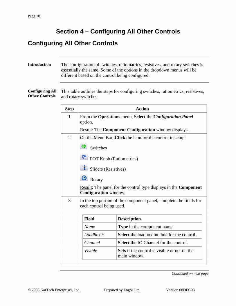
Configuring All Other Controls
Introduction The configuration of switches, ratiomatrics, resistives, and rotary switches is
essentially the same. Some of the options in the dropdown menus will be different based on the control being configured.
Configuring All Other Controls
This table outlines the steps for configuring switches, ratiometrics, resistives, and rotary switches.
Step Action
1 From the Operations menu, Select the Configuration Panel option.
Result: The Component Configuration window displays.
2 On the Menu Bar, Click the icon for the control to setup.
Switches
POT Knob (Ratiometrics)
Sliders (Resistives)
Rotary
Result: The panel for the control type displays in the Component Configuration window.
3 In the top portion of the component panel, complete the fields for each control being used.
Field Description
Name Type in the component name.
Loadbox # Select the loadbox module for the control.
Channel Select the IO Channel for the control.
Visible Sets if the control is visible or not on the main window.
Continued on next page

Page 71
© 2008 GarTech Enterprises, Inc. Prepared by Logos Ltd. Version 08DEC08
Configuring All Other Controls, Continued
Configuration Panel
This graphic illustrates the panel for configuring other controls. This specifically illustrates a portion of the Switches panel.
Continued on next page

Page 72
© 2008 GarTech Enterprises, Inc. Prepared by Logos Ltd. Version 08DEC08
Configuring All Other Controls, Continued
Configuring All Other Controls, Continued
This table continues to outline the steps for configuring switches, ratiometrics, resistives, and rotary switches.
Step Action
3 Continued
Field Description
Function Select the function of the control.
Default Sets the default value for the control when the configuration is loaded or the control is reset
Min Type the minimum value for the component. This value will display on the gauge, and it must be a whole number.
Max Type the maximum value for the component. This value will display on the gauge, and it must be a whole number.
Digits Select the significant digits for the component.
Multiplier Type the multiplier to scale the component.
Interlock Allows component’s values to be locked together. Select the component to which this component should be locked.
Interlock OP Allows the user to determine if interlocked components should be Non-Inverting or Inverting.
Table Sets the interpolation table for this component.
4 When the changes are complete, Save the configuration.
Note: To immediately apply the setup to the front panel, from the File menu Select the Apply Configuration option.
Continued on next page

Page 73
© 2008 GarTech Enterprises, Inc. Prepared by Logos Ltd. Version 08DEC08
Configuring All Other Controls, Continued
Configuration Panel
This graphic illustrates the panel for configuring other controls. This specifically illustrates a portion of the Switches panel.

Page 74
© 2008 GarTech Enterprises, Inc. Prepared by Logos Ltd. Version 08DEC08
Section 5 – Configuration Options
Configuration Options
Introduction The Configuration Options allows the user to name the tabs on the main
window as well as hide tabs that are not being used.
Configuration Options
This table outlines the steps for setting the configuration options.
Step Action
1 From the Operations menu, Select the Configuration Panel option. Result: The Component Configuration window displays.
2 On the Menu Bar, Click the Configuration Options icon . Result: The Configuration Options panel displays in the Component Configuration window.
3 In the Visibility field, Deselect any tab that should be hidden on the main window.
4 In the Tab Name field, Click on a tab name to change and Type the new name.
5 When the changes are complete, Save the configuration.
Note: To immediately apply the setup to the front panel, from the File menu Select the Apply Configuration option.
Continued on next page

Page 75
© 2008 GarTech Enterprises, Inc. Prepared by Logos Ltd. Version 08DEC08
Configuration Options, Continued
Configuration Options Panel
This graphic illustrates the Configuration Options panel on the Component Configuration window.

Page 76
© 2008 GarTech Enterprises, Inc. Prepared by Logos Ltd. Version 08DEC08
Notes

Page 77
© 2008 GarTech Enterprises, Inc. Prepared by Logos Ltd. Version 08DEC08
Chapter 4 – The FMET Interface
Overview
Introduction The Failure Mode Effects Test, FMET, is a set of actions performed during a
Failure Mode Effects Analysis, FMEA. An FMEA requires the user to create specific failure situations and determine the results of those failures on multiple I/O. The GarTech FMET Box provides the ability to perform a Failure Mode Effects Test preliminarily on a bench with a LUIS as well as mounted in a system for real-world testing. It allows the user to interrupt and short ECM lines to specific fault conditions like VBATT and Ground. The GarTech FMET Interface provides a graphical user interface for communicating with the FMET box.
Physical Description
The FMET box is approximately 9”x12”x3.5”. The box can be mounted in the engine compartment to reduce wire lengths. In normal off conditions, the FMET box simply passes all of the harness signals through.
In This Chapter
This table outlines the topics covered in this chapter.
Topic See Page
How To Connect an FMET Box 78
FMET Workflow 79
The FMET Graphical Interface 70

Page 78
© 2008 GarTech Enterprises, Inc. Prepared by Logos Ltd. Version 08DEC08
Section 1 – How To Connect an FMET Box
How To Connect an FMET Box
Introduction The FMET box has a CAN interface, and only a datalink wire is required to
connect the PC to the box.
Connecting the FMET Box
The FMET box is connected between the ECM and the Harness. To connect the FMET box, disconnect the wiring harness from the ECM and connect it into the FMET box cable and then back into the ECM.

Page 79
© 2008 GarTech Enterprises, Inc. Prepared by Logos Ltd. Version 08DEC08
Section 2 – FMET Workflow
FMET Workflow
FMET Workflow
This diagram illustrates the workflow for completing tests using the FMET Interface. This workflow assumes that all hardware is already connected.
Set Up or LoadComponent
Configuration File(I/O Controls)
Flip the RelaySwitches to Apply
the Fault To(I/O Controls)
Flip the ApplyFault Switch to
Indicate Where toApply the Fault
(APPLY FAULT)
Check the COMStatus andCURRENT
Status(STATUS)
DidExclusionWarningDisplay?
Change Relays orModify
Exclusions(Component
Configuration)
Errors? Check Hardwareas Required
Flip the FaultSwitch to Apply
(FAULTS)
DidExclusionWarningDisplay?
Change Relays orModify
Exclusions(Component
Configuration)
Watch for Errorsas Test
Completes
Yes
Yes
Yes
No
No
No

Page 80
© 2008 GarTech Enterprises, Inc. Prepared by Logos Ltd. Version 08DEC08
Section 3 – The FMET Graphical Interface
Overview
Introduction The FMET Interface provides a graphical interface for communicating with
the FMET box. The FMET Interface is a part of the LUIS Graphical User Interface
How To Access the FMET Graphical Interface
To access the FMET Interface, from the LUIS Graphical Interface, Open the Hardware menu. From the Hardware menu, Select the FMET Unit option. The FMET Interface displays.
The FMET Interface
The FMET Interface is made up of six basic sections: Menu Bar, Toolbar, Faults Switches, Apply Fault Switches, Status Indicators and I/O Controls.
Continued on next page

Page 81
© 2008 GarTech Enterprises, Inc. Prepared by Logos Ltd. Version 08DEC08
Overview, Continued
In This Section This table outlines the topics covered in this section.
Topic See Page
Menu Bar 82
Toolbar 83
Faults Switches 84
Apply Fault Switches 85
Status Indicators 86
I/O Controls 88
Page 82
© 2008 GarTech Enterprises, Inc. Prepared by Logos Ltd. Version 08DEC08
Menu Bar
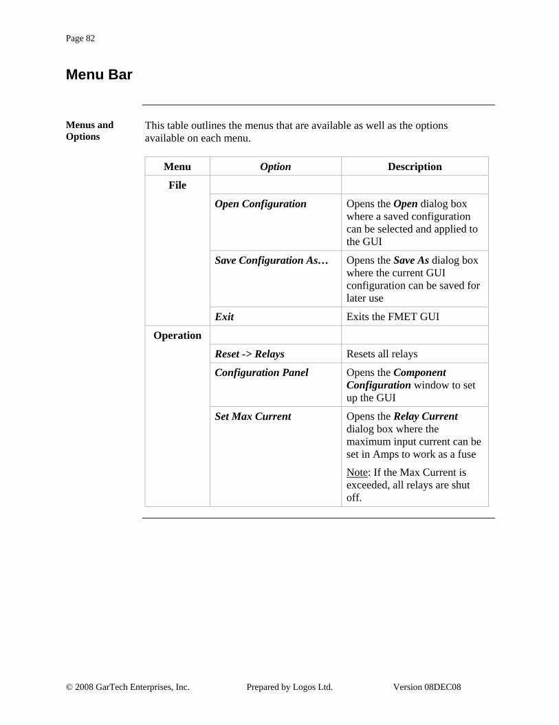
Menus and Options
This table outlines the menus that are available as well as the options available on each menu.
Menu Option Description
File
Open Configuration Opens the Open dialog box where a saved configuration can be selected and applied to the GUI
Save Configuration As… Opens the Save As dialog box where the current GUI configuration can be saved for later use
Exit Exits the FMET GUI
Operation
Reset -> Relays Resets all relays
Configuration Panel Opens the Component Configuration window to set up the GUI
Set Max Current Opens the Relay Current dialog box where the maximum input current can be set in Amps to work as a fuse
Note: If the Max Current is exceeded, all relays are shut off.
Page 83
© 2008 GarTech Enterprises, Inc. Prepared by Logos Ltd. Version 08DEC08
Toolbar
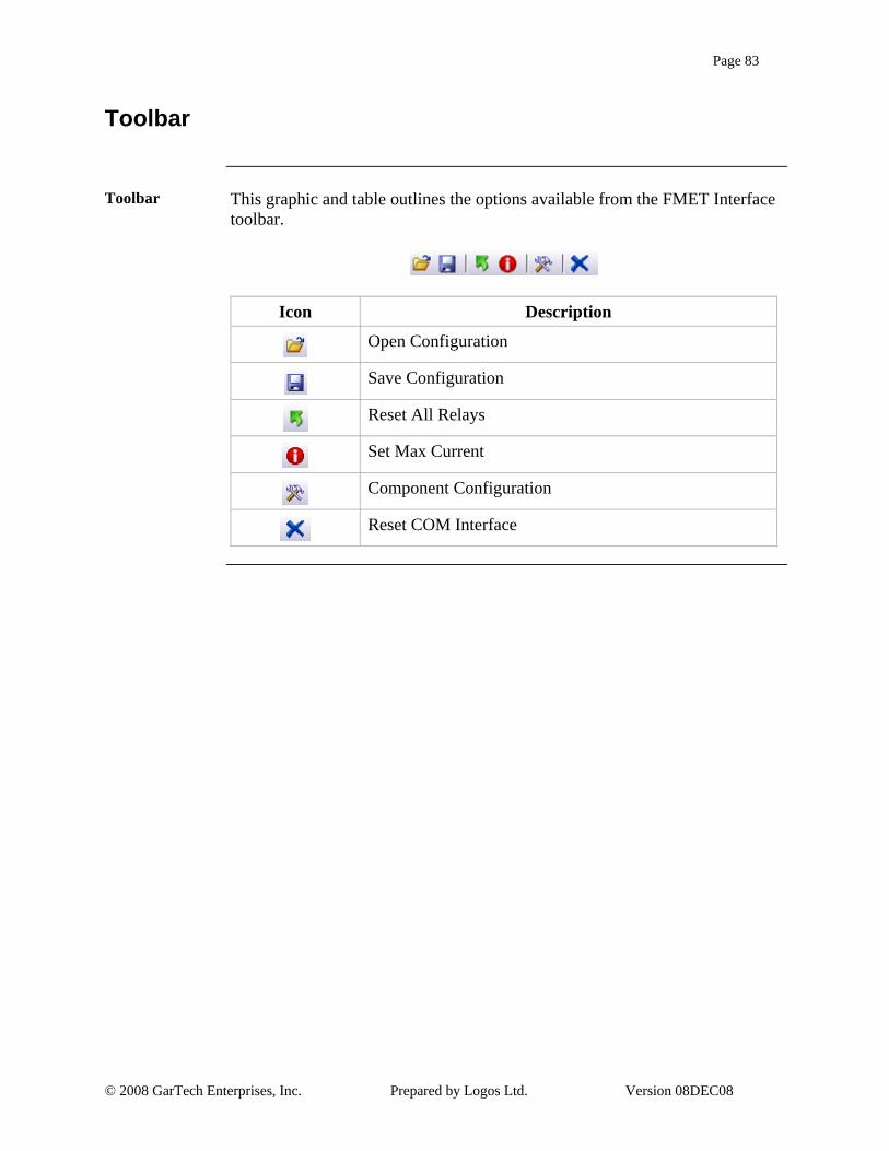
Toolbar This graphic and table outlines the options available from the FMET Interface
toolbar.
Icon Description
Open Configuration
Save Configuration
Reset All Relays
Set Max Current
Component Configuration
Reset COM Interface

Page 84
© 2008 GarTech Enterprises, Inc. Prepared by Logos Ltd. Version 08DEC08
Fault Switches
Faults Switches The Faults switches are used to apply a fault to all the selected I/O channels.
The generic faults are: Open, VBATT and Ground. There are two additional customizable faults that are labeled FAULT1 and FAULT2 in the FMET Interface.
Switch Positions
The Faults switches can be in the ON or OFF position. The switch is in the ON position when the switch name is displayed in red and the top of the rocker switch is depressed. The switch is in the OFF position when the switch name is displayed in black and the bottom of the rocker switch is depressed.

Page 85
© 2008 GarTech Enterprises, Inc. Prepared by Logos Ltd. Version 08DEC08
Apply Fault Switches
Apply Fault Switches
The Apply Fault switches are used to set how the fault is to be applied. The appropriate Apply Fault switch should be set before flipping the Faults switch. This following table describes the possibilities.
Switch Setting Apply Fault Through
ECM/HARN ECM and Harness
ECM ECM Only
HARNESS Harness Only
Switch Positions
The switches indicate which Apply Fault option is selected by displaying its name in red and showing the switch depressed in that direction. Clicking the Harness switch toggles between Harness being selected or ECM being selected, as the lower position of the Harness switch defaults back to ECM.

Page 86
© 2008 GarTech Enterprises, Inc. Prepared by Logos Ltd. Version 08DEC08
Status Indicators
Status Indicators
The status indicators section provides information on the COM Status, the current draw, in amps, through the relays on each board, as well as the status of each board.
COM Status The COM Status indicator tells the user the current state of the hardware. This
table describes the common messages. Message Description Basic Troubleshooting
OK Hardware has been found and is ready
ILLHW Hardware cannot be found Check hardware connections
HWINUSE Hardware is in use by another device
Wait until status changes to OK
BUSLIGHT CAN Error Reset COM Interface
BUSHEAVY CAN Error Reset COM Interface
BUSOFF Can device is off Check CAN device and then reset COM Interface
Continued on next page

Page 87
© 2008 GarTech Enterprises, Inc. Prepared by Logos Ltd. Version 08DEC08
Status Indicators, Continued
Current (Amps)
The Current (Amps) section of the Status Indicators shows the status of each of the possible six boards. When a board is on-line its status light will be green, otherwise it will be black. When a board is on-line, if the cursor is held over the status light, the revision of the code that is in the mirco displays.
For each board that is on-line, the draw of all its possible 30 relays is measured and the highest draw is displayed in Amps. If the cursor is held over the Amps display, the name of the relay with the highest draw on that board will be displayed.
Highest Draw in Amps
On-Line / Off-Line Indicator

Page 88
© 2008 GarTech Enterprises, Inc. Prepared by Logos Ltd. Version 08DEC08
I/O Controls
Introduction The I/O Control switches are divided up into tabs for each of the six possible
boards. The Component Configuration window is used to set up the boards, the switches available as well as switch and fault exclusions.
The Component Configuration Window
The Component Configuration window for the FMET Interface is very similar, but not identical, to the Component Configuration window in the LUIS Interface. The File menu is the same, but the Component menu only offers two choices, Relay and Exclusion List. The Tools menu does not provide a Table option, since tables are not used for FMET.
Configuring the I/O Controls
This table outlines the steps for configuring the I/O Controls.
Step Action
1 From the Operation menu, Select the Configuration Panel option.
Result: The Component Configuration window displays
Modifying Tabs
2 To add or remove tabs for boards, from the Tools menu, Select the Configuration Options option.
Result: The Configuration Options panel displays
3 To add a tab, in the Tab Name field, Type the name of the tab, and Click the Visibility field to display a green checkmark.
4 To remove a tab, Click the Visibility tab to clear the green checkmark.
5 Once the tab names have been entered and the visibility has been set, save the configuration by Clicking the Save As icon on the toolbar or Selecting the Save Configuration As option from the File menu.
Continued on next page

Page 89
© 2008 GarTech Enterprises, Inc. Prepared by Logos Ltd. Version 08DEC08
I/O Controls, Continued
Component Configuration Window
This is an example of the Component Configuration window.
Configuration Options Panel
This is an example of the Configuration Options panel.
Continued on next page

Page 90
© 2008 GarTech Enterprises, Inc. Prepared by Logos Ltd. Version 08DEC08
I/O Controls, Continued
Configuring the I/O Controls, Continued
This table continues to outline the steps for configuring the I/O Controls.
Step Action
6 Once the configuration is complete and has been saved, Click the Apply icon on the toolbar or Select the Apply option from the Tools menu. Result: The Apply Configuration dialog box displays to confirm that the configuration should be applied. Click the <Yes> button to continue. The changes are immediately implemented.
Configuring Switches 7 To configure the switches found on each tab, from the
Component menu, Select the Relays option or Click the Relays icon on the toolbar. Result: The relay configuration panel displays with all possible switches listed.
8 For each switch being used, modify the fields as necessary. Note: Multiple switches can be set up for the same I/O pin. The same I/O pin can appear more than once on a single tab, or it can appear on multiple tabs.
Field Description Name Type a name for the switch.
Note: This is the name that will display on the FMET interface. It is not required.
Relay Board # Select the appropriate relay board from the drowndown list.
Relay # Select the correct relay # from the dropdown list.
Continued on next page

Page 91
© 2008 GarTech Enterprises, Inc. Prepared by Logos Ltd. Version 08DEC08
I/O Controls, Continued
Relay Configuration Panel
This is an example of the relay configuration panel.
Continued on next page

Page 92
© 2008 GarTech Enterprises, Inc. Prepared by Logos Ltd. Version 08DEC08
I/O Controls, Continued
Configuring the I/O Controls, Continued
This table continues to outline the steps for configuring the I/O Controls.
Step Action
8 Continued
Field Description Visible If the relay should be visible, ensure that a
green checkmark displays, otherwise make sure that the field is blank.
ToolTip Type a brief description to display if the mouse is hovered over the switch. Note: The ToolTip is most commonly used to display Connector Numbers with Pin Number on the ECM.
9 To rearrange switches, use the Move Up and Move Down icons on the toolbar, or the Move Up and Move Down options from the Tools menu.
10 Once the switches are all set as needed, save the configuration by Selecting the Save Configuration As option from the File menu or Clicking the Save As icon in the toolbar.
Note: The Print icon on the toolbar, or the Print option on the File menu can be used to easily review the configuration and box connections.
11 Once the configuration is complete and has been saved, Click the Apply icon on the toolbar or Select the Apply option from the Tools menu.
Result: The Apply Configuration dialog box displays to confirm that the configuration should be applied. Click the <Yes> button to continue. The changes are immediately implemented.
Continued on next page

Page 93
© 2008 GarTech Enterprises, Inc. Prepared by Logos Ltd. Version 08DEC08
I/O Controls, Continued
Relay Configuration Panel
This is an example of the relay configuration panel.
Continued on next page

Page 94
© 2008 GarTech Enterprises, Inc. Prepared by Logos Ltd. Version 08DEC08
I/O Controls, Continued
Configuring the I/O Controls, Continued
This table continues to outline the steps for configuring the I/O Controls.
Step Action
Setting Exclusions
12 Exclusions can be set to prevent relays from tripping under certain conditions. To set exclusions, Click the Exclusions icon on the toolbar or Select the Exclusion List option from the Component menu.
Result: The Exclusion List panel displays.
13 To set an exclusion, in the first Name field, Select the appropriate relay or fault from the dropdown list. In the second Name field, Select the appropriate relay or fault from the dropdown list.
Note: Exclusions are mutually exclusive. It doesn’t matter which relay or fault is listed first or second. As long as one relay is switched ON the other cannot be switched ON.
Result: The Relay No. fields are automatically populated.
14 The <Delete> button can be used to remove exclusions.
17 Once all the exclusions have been set, save the configuration by Selecting the Save Configuration As option from the File menu or Clicking the Save As icon in the toolbar.
18 Once the exclusions have been set and saved, Click the Apply icon on the toolbar or Select the Apply option from the Tools menu.
Result: The Apply Configuration dialog box displays to confirm that the configuration should be applied. Click the <Yes> button to continue. The changes are immediately implemented.
19 Once the boards, relays and exclusions have been set, saved and applied, close the Component Configuration window.
Note: If the FMET Interface does not reflect the changes made, the changes must not have been applied. Re-open the Component Configuration window, load the saved configuration files and Apply the changes.
Continued on next page

Page 95
© 2008 GarTech Enterprises, Inc. Prepared by Logos Ltd. Version 08DEC08
I/O Controls, Continued
Exclusion List Panel
This is an example of the Exclusion List panel.

Page 96
© 2008 GarTech Enterprises, Inc. Prepared by Logos Ltd. Version 08DEC08
Notes

Page 97
© 2008 GarTech Enterprises, Inc. Prepared by Logos Ltd. Version 08DEC08
Chapter 5 – Appendix
Overview
Introduction The following topics discuss some details of LUIS specifications and
troubleshooting methods.
In This Section This table outlines the topics covered in this chapter.
Topic See Page
Waveforms 98
RS232 Interface 99
DAC Specifics 101
Address Switch 102
Table Calibration 103
Troubleshooting 105
Connectors and Pinout 110
CAN Protocol 119
Multi-Parent Setup 128

Page 98
© 2008 GarTech Enterprises, Inc. Prepared by Logos Ltd. Version 08DEC08
Section 1 – Waveforms
Waveforms
Introduction The Wavemaker inside of LUIS has built in support for specific waveform
data. The user can select specific waveforms from the Configuration Screen and these will be loaded on power cycle. Only one waveform is needed to load both waveforms into the first two channels.
Waveform Data
This table describes the current support for the specific waveforms.
Waveform Number Action
1 60-2 / 6+1 Hall (ISB)
2 24+1 / 24+1 VR
3 60-2 / 6+1 Hall (HHP)
4 24+1 / 24+1 Hall
5 60-2 / 12+1 Hall (MY07)
6 60-2 / 24+1 Hall (HHP 45/60)
7 N/A
8 N/A
9 60-2 / 12+1 Hall (MY07)
10 N/A
11 60-2 / 8+1 Hall
12 N/A
13 60-2 / 4+1 Hall
14 N/A
15 N/A

Page 99
© 2008 GarTech Enterprises, Inc. Prepared by Logos Ltd. Version 08DEC08
Section 2 – RS232 Interface
RS232 Interface
Introduction The RS232 port on the rear panel of LUIS supports eight commands. The
port setup is 19.2k bits per second, 8 data bits, No Parity, 1 stop bit, and No flow control.
RS232 Commands
This table describes the valid RS232 commands.
Description Symbol Format Example Rear Axle Ratio Change A Rear axle ratio as a floating
point number. The decimal point is always the 3rd character. If less than 10, a leading zero must be included. Data range: 0 - 99.99
A05.29XXX sets the new rear axle ratio to 5.29. The vehicle speed signal will be recalculated with the new RAR value.
Waveform type change request. This parameter allows the user to select from a list of available crank and cam waveforms. The system will produce waveforms based on default settings
E Waveform Type as a whole number. If less than 10, a leading zero must be included
E011500XX sets the new waveform to type "01" and the new engine speed request to 1500rpm
Fan speed change request F Fan Speed as a whole number in RPM. Leading zero(s) must be included for and speed request smaller than 1000 RPM. Data range 0 - 9999
F1234XXXX sets the new Fan Speed to 1,234 RPM
Turbo speed change request G Turbo speed as a floating point number in KRPM. Leading zero(s) must be included for any speed request smaller than 100 KRPM. Data range: 0 - 999.9
G012.4XXXX sets the new turbo speed to 12,400 RPM
VSS teeth per interrupt change request.
I Number of teeth per interrupt as a whole number. If less than 10, a leading zero must be included. Data Range: 0 - 99
I16XXXXXX sets the new teeth per interrupt values. The vehicle speed signal will be recalculated with the new value.
Continued on next page

Page 100
© 2008 GarTech Enterprises, Inc. Prepared by Logos Ltd. Version 08DEC08
RS232 Interface, Continued
RS232 Commands, Continued
This table continues to describe the valid RS232 commands.
Description Symbol Format Example ESS/EPS change request R Engine speed as a whole
number in RPM. Leading zeros must be added for any speed request smaller than 1000 RPM. Data range: 0 - 9999
R1234XXXX sets the new ESS/EPS speed to 1,234 RPM.
Tire size change request T Tire size as a whole number in revolutions per mile. If less than 100, leading zero(s) must be included.
T508XXXXX sets the new tire size to 508 rev/mile. The vehicle speed signal will be recalculated with the new value
Vehicle speed change request V Vehicle speed as a floating point number in MPH. If less than 100, leading zero(s) must be included. Data range: 0 - 999.99
V012.34XX sets the new vehicle speed to 12.34 MPH.
Channel Assignment
The following table lists the I/O channel assignments that must be followed when sending commands via the RS232 interface.
Analog Outputs Channel Numbers
Parent Box 1-32
Parent Sidecar 33 - 44
Child 1 Box 45 - 76
Child 2 Box 77 - 108
Switches Channel Numbers
Parent Box 1 - 32
Parent Sidecar 33 - 40
Child 1 Box 41 - 72
Child 2 Box 73 - 104

Page 101
© 2008 GarTech Enterprises, Inc. Prepared by Logos Ltd. Version 08DEC08
Section 3 – DAC Specifics
DAC Specifics
Introduction The LUIS hardware has limitations on how accurate it can represent an
Analog voltage. These limitations are based on the Digital to Analog Converters (DAC’s) that are used to output the analog voltage.
DAC Limits This table describes the DAC limitations.
Component DAC Resolution Reference Voltage Limit
Parent Box 12 Bits 5.5v
Parent Sidecar Ch 1-8: 12 Bits
Ch 9-12: 8 Bits
Ch 1-8: 5.5v
Chan 9-12: 32v
Child 1 Box 12 Bits 5.5v
Child 2 Box 12 Bits 5.5v
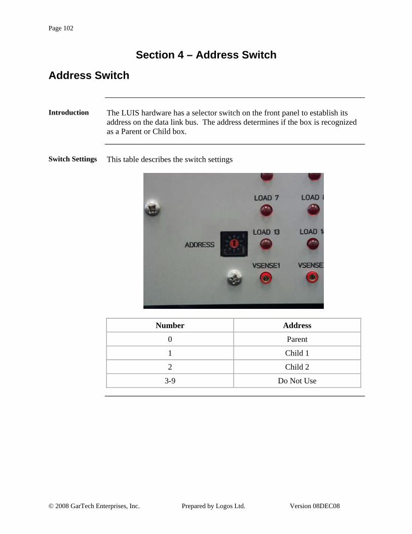
Page 102
© 2008 GarTech Enterprises, Inc. Prepared by Logos Ltd. Version 08DEC08
Section 4 – Address Switch
Address Switch
Introduction The LUIS hardware has a selector switch on the front panel to establish its
address on the data link bus. The address determines if the box is recognized as a Parent or Child box.
Switch Settings This table describes the switch settings
Number Address
0 Parent
1 Child 1
2 Child 2
3-9 Do Not Use

Page 103
© 2008 GarTech Enterprises, Inc. Prepared by Logos Ltd. Version 08DEC08
Section 5 – Table Calibration
Table Calibration
Introduction LUIS uses look up tables to correlate engineering units that are on the GUI
interface to analog values that it outputs to the unit under test. The user can adjust these values so the engineering units on the GUI match what the unit under test calculates it to be.
Table Calibration
This table describes the table calibration procedure.
Step Action
1 From the Operations menu, Select the Configuration Panel option.
Result: The Component Configuration window displays.
2 On the Menu Bar, Click the Tables icon .
Result: The Table panel displays in the Component Configuration window.
3 Select the table from the list of tables that need to be calibrated.
4 The table first needs to be very simple so a full range can be achieved. This is done by setting two full range points for the sensor. In the table data on the left pane on line 1 enter 0 counts and 0 for Eng Units.
5 On line 2 enter 1023 for counts and the maximum engineering unit (i.e. 100 for 100% throttle). Delete all other entries for the table.
6 Connect a tool that can communicate with the unit under test and display the parameters that need to be calibrated.
7 Go back to the LUIS Main panel and slowly adjust the knob/slider until the tool that’s communicating to the unit under test reads the lowest reading (i.e. when throttle goes from 0% to 1%). Record the LUIS value.
Continued on next page

Page 104
© 2008 GarTech Enterprises, Inc. Prepared by Logos Ltd. Version 08DEC08
Table Calibration, Continued
Table Calibration, Continued
This table continues to describe the table calibration procedure.
Step Action
8 Continue slowly increasing the knob/slide on LUIS GUI until the tool that’s communicating to the unit under test reads the maximum value for that sensor (i.e. when throttle is at 100%). Record the value that is on the LUIS GUI.
9 In the LUIS table for that sensor, change the first count value in row one to (1023 * LUIS first value) and in row two (1023 * LUIS second value). The table now has two valid points and is complete.

Page 105
© 2008 GarTech Enterprises, Inc. Prepared by Logos Ltd. Version 08DEC08
Section 6 – Troubleshooting
Troubleshooting COM Status
Introduction LUIS has a number of cable connections and is a complex electronic test
instrument. The items listed in this section describe the most common issues that might arise while using LUIS.
Troubleshooting COM Status
To troubleshoot the COM Status, read the COM Status on the top right of the LUIS GUI and refer to the table on the next page.
Note: After making corrections to the setup, the <Reset COM Interface> button may need to be clicked.
Continued on next page

Page 106
© 2008 GarTech Enterprises, Inc. Prepared by Logos Ltd. Version 08DEC08
Troubleshooting COM Status, Continued
COM Status This table gives troubleshooting suggestions based on the COM Status on the
top right of the LUIS GUI.
COM Status Action
OK Check the lamp indicators just below the COM Status on the LUIS GUI. If the load box light is not ON, make sure power for all the load boxes is turned ON. If your load box has a sidecar circuit, verify that the CAN cable connections in the back of the sidecar are plugged into the Parent box and your PC is connected into the sidecar CAN connector.
Note: For more information, see Section 2 - How to Setup A LUIS in this document.
BUSHEAVY, OVERRUN
Usually caused by bad connection from the Peak adapter to LUIS or an improper amount of CAN cable termination resistors. The LUIS hardware requires a minimum of one and maximum of two 120 ohm termination resistors on the CAN bus for proper operation. For more information about how to construct a CAN node see the SAE J1939-11 specification. Also could be the result of other datalink devices on the CAN bus using an inappropriate amount of bandwidth.
BUSOFF Check the Peak adapter settings in the NetConfig software that gets installed with LUIS by Clicking <Start> -> All Programs -> PCAN -> NetConfig. After running this program, Select PEAK USB-CAN, (select PCI if your setup uses a PCI-to-CAN adapter), from the list and then select the Net. Edit the Net and verify that the CAN baud rate is set for 250Kbit/sec. Also see BUSHEAVY section.
Continued on next page

Page 107
© 2008 GarTech Enterprises, Inc. Prepared by Logos Ltd. Version 08DEC08
Troubleshooting COM Status, Continued
COM Status, Continued
This table continues to give troubleshooting suggestions based on the COM Status on the top right of the LUIS GUI.
COM Status Action
ILLHW Open up Control Panel in Windows and DoubleClick on the CAN Hardware icon. Select the USB radio button at the top of the screen and Click <OK>, (select PCI if your setup uses a PCI-to-CAN adapter). Restart LUIS.
Verify that the Net name that the LUIS software is using is the connected to the hardware. In LUIS Select Hardware->Peak Adapter->Set Net Name. This name must be the same as the one in NetConfig software. Run the NetConfig software by Clicking <Start> -> All Programs -> PCAN -> NetConfig. Then select the Peak adapter being used. The Nets for that device are then listed underneath and one of the Nets should match what LUIS is set for. The default Net name for LUIS is LUIS_Net_1. The bus speed must be set to 250Kbit/sec.
NOVXD Verify that the PEAK adapter is plugged into your PC’s USB port or PCI slot. If not, connect the adapter and re-start the LUIS program.
HWINUSE Another application is using the Peak hardware and not using the same Net name that LUIS is using. Change the Net name in LUIS by selecting Hardware->Peak Adapter->Set Net Name to the same name as the other application.

Page 108
© 2008 GarTech Enterprises, Inc. Prepared by Logos Ltd. Version 08DEC08
Troubleshooting Closed Loop Engine Speed
Troubleshooting Closed Loop Engine Speed
These tables outline the steps for troubleshooting Closed Loop Engine Speed.
Symptom: Engine does not start, RPM gauge does not move.
Step Action
1 Verify that the LOAD BOX STATUS indicator lamps are working correctly.
Note: In most cases this means that Parent, Sidecar and Wavemaker are all Online.
2 Verify to following:
• ECM wiring harness is fully connected
• VBATT power supply is connected to LUIS and turned on
• VBATT switch on LUIS GUI is turned ON
• Key switch is turned ON
• Verify correct LUIS configuration file is loaded for ECM under test
• Set PERCENT LOAD slider to 0
• Set GAIN ADJUST slider to 300
• Set OPEN/CLOSED loop switch to CLOSED loop. If already in CLOSED position, toggle to OPEN and back to CLOSED loop
• ECM under test supports J1939 broadcast of Percent Load and Engine Speed
Continued on next page

Page 109
© 2008 GarTech Enterprises, Inc. Prepared by Logos Ltd. Version 08DEC08
Troubleshooting COM Status, Continued
Troubleshooting Closed Loop Engine Speed, Continued
These tables continue to outline the steps for troubleshooting Closed Loop Engine Speed.
Symptom: Engine RPM dies without reaching idle RPM
Step Action
1 Verify PERCENT LOAD slider is set to 0.
2 Increase GAIN ADJUST slider and try again.
3 Verify the ECM control software is not trying to command a shutdown.
Symptom: Engine RPM does not respond to Throttle input.
Step Action
1 Verify there are no active ECM faults which cause fueling and/or speed derates.
2 If ECM calibration required idle validation, turn on the LUIS AUTO IVS switch. Cycle the throttle a few times to eliminate Throttle and IVS fauly codes.
Symptom: Engine RPM is unstable
Step Action
1 Adjust GAIN ADJUST slider and PERCENT LOAD sliders until RPM becomes stable.

Page 110
© 2008 GarTech Enterprises, Inc. Prepared by Logos Ltd. Version 08DEC08
Section 7 – Connectors and Pinout
Connectors
Introduction The Parent LUIS box has three 50 pin connectors on top that interface the
load box to the unit under test. These interface connectors are all Deutsch 50 pin connectors. The Sidecar also has a 50 pin connector, and an additional 1 or 2 rear panel green connectors. The pinout of the green connectors may be application specific. Please consult your ECM’s LUIS wiring diagram for green connector pinout information.
Connectors This table describes the connector pinout information.
Unit Connectors
Parent 50-01, 50-02, 50-03
Sidecar 50-04
Child 1 50-01, 50-02, 50-03
Child 2 50-01, 50-02, 50-03

Page 111
© 2008 GarTech Enterprises, Inc. Prepared by Logos Ltd. Version 08DEC08
Connector Pinout – Parent/Child 1/Child 2/ Pin Key 01
Parent/Child 1/ Child 2/ Pin Key 01
This table gives the connector pinout for Parent/Child 1/Child 2/Pin Key 01.
Pin Function I/O Range Notes 1 Lamp 3 low side IN 0-VBATT Low side driver input for front panel LED (high
side = key switch) 2 Lamp 4 low side IN 0-VBATT Low side driver input for front panel LED (high
side = key switch) 3 Lamp 5 low side IN 0-VBATT Low side driver input for front panel LED (high
side = key switch) 4 5.5V OUT LUIS power supply reference output 5 AD0 IN 0-3.3v Analog signal input with internal 10k pullup to
3.3v 6 AD1 IN 0-3.3v Analog signal input with internal 10k pullup to
3.3v 7 Ground OUT Unswitched Battery Return 8 N/C Not used 9 N/C Not used
10 N/C Not used 11 N/C Not used 12 Load 8A IN 47 ohm Connect to driven side of Load 13 Load 1+ IN 47 ohm High side of Load (low side = ground) 14 Load 2+ IN 47 ohm High side of Load (low side = ground) 15 Load 3+ IN 47 ohm High side of Load (low side = ground) 16 Load 4+ IN 47 ohm High side of Load (low side = ground) 17 Load 5+ IN 47 ohm High side of Load (low side = ground) 18 Load 6+ IN 47 ohm High side of Load (low side = ground) 19 Load 7A IN 47 ohm Connect to driven side of load 20 Load 7B IN 47 ohm Connect to common side of load 21 N/C Not used 22 Load 8B IN 47 ohm Connect to common side of load 23 Load 9A IN 47 ohm Connect to driven side of load 24 Load 9B IN 47 ohm Connect to common side of load 25 Ground OUT Unswitched Battery Return
Continued on next page

Page 112
© 2008 GarTech Enterprises, Inc. Prepared by Logos Ltd. Version 08DEC08
Connector Pinout – Parent/Child 1/Child 2/ Pin Key 01, Continued
Parent/Child 1/ Child 2/ Pin Key 01, Continued
This table continues to give the connector pinout for Parent/Child 1/Child 2/Pin Key 01.
Pin Function I/O Range Notes 26 Lamp 1 low side IN 0-VBATT Low side driver input for front panel LED (high
side = key switch) 27 Lamp 2 low side IN 0-VBATT Low side driver input for front panel LED (high
side = key switch) 28 Load 18B IN 10k Connect to common side of load 29 Load 18A IN 10k Connect to driven side of load 30 Load 17B IN 10k Connect to common side of load 31 Load 17A IN 10k Connect to driven side of load 32 Load 16B IN 47 ohm Connect to common side of load 33 Load 16A IN 47 ohm Connect to driven side of load 34 Ground OUT 35 Ground OUT 36 Ground OUT 37 Ground OUT 38 Ground OUT 39 Load 15B IN 47 ohm Connect to common side of load 40 Load 15A IN 47 ohm Connect to driven side of load 41 Load 14B IN 47 ohm Connect to common side of load 42 Load 14A IN 47 ohm Connect to driven side of load 43 Load 13B IN 47 ohm Connect to common side of load 44 Load 13A IN 47 ohm Connect to driven side of load 45 Load 12B IN 47 ohm Connect to common side of load 46 Load 12A IN 47 ohm Connect to driven side of load 47 Load 11B IN 47 ohm Connect to common side of load 48 Load 11A IN 47 ohm Connect to driven side of load 49 Load 10B IN 47 ohm Connect to common side of load 50 Load 10A IN 47 ohm Connect to driven side of load

Page 113
© 2008 GarTech Enterprises, Inc. Prepared by Logos Ltd. Version 08DEC08
Connector Pinout – Parent/Child 1/Child 2/ 50 Pin Key 02
Parent/Child 1/ Child 2/ 50 Pin Key 02
This table gives the connector pinout for Parent/Child 1/Child 2/50 Pin Key 02.
Pin Function I/O Range Notes 1 Channel 1 OUT 0-? Open collector output (requires external pullup) 2 Channel 2 OUT 0-? Open collector output (requires external pullup) 3 Channel 3 OUT 0-? Open collector output (requires external pullup) 4 Channel 4 OUT 0-? Open collector output (requires external pullup) 5 Channel 5 OUT 0-? Open collector output (requires external pullup) 6 Channel 6 OUT 0-? Open collector output (requires external pullup) 7 Channel 7 OUT 0-? Open collector output (requires external pullup) 8 Channel 8 OUT 0-? Open collector output (requires external pullup) 9 Channel 9 OUT 0-? Open collector output (requires external pullup)
10 Channel 10 OUT 0-? Open collector output (requires external pullup) 11 Channel 11 OUT 0-? Open collector output (requires external pullup) 12 Channel 12 OUT 0-? Open collector output (requires external pullup) 13 Channel 13 OUT 0-? Open collector output (requires external pullup) 14 Channel 14 OUT 0-? Open collector output (requires external pullup) 15 Channel 15 OUT 0-VSENS1 Sensor output 16 Channel 16 OUT 0-VSENS1 Sensor output 17 Channel 17 OUT 0-VSENS2 Sensor output 18 Channel 18 OUT 0-VSENS2 Sensor output 19 Channel 19 OUT 0-VSENS2 Sensor output 20 Channel 20 OUT 0-VSENS2 Sensor output 21 Channel 21 OUT 0-VSENS3 Sensor output 22 Channel 22 OUT 0-VSENS3 Sensor output 23 Channel 23 OUT 0-VSENS3 Sensor output 24 Channel 24 OUT 0-VSENS3 Sensor output 25 Channel 25 OUT 0-VSENS4 Sensor output
Continued on next page

Page 114
© 2008 GarTech Enterprises, Inc. Prepared by Logos Ltd. Version 08DEC08
Connector Pinout – Parent/Child 1/Child 2/ 50 Pin Key 02, Continued
Parent/Child 1/ Child 2/ 50 Pin Key 02, Continued
This table continues to give the connector pinout for Parent/Child 1/Child 2/50 Pin Key 02.
Pin Function I/O Range Notes 26 Channel 26 OUT 0-VSENS4 Sensor output 27 Channel 27 OUT 0-VSENS4 Sensor output 28 Channel 28 OUT 0-VSENS4 Sensor output 29 Private CAN+ IN No internal connection 30 Private CAN- IN No internal connection 31 Private CAN Shield IN No internal connection 32 Public J1939+ I/O LUIS control / monitor datalink 33 Public J1939- I/O LUIS control / monitor datalink 34 Public J1939 Shield IN LUIS control / monitor datalink 35 Ground OUT Sensor output 36 Ground OUT Sensor output 37 Ground OUT Sensor output 38 Ground OUT Sensor output 39 Ground OUT Sensor output 40 VSENS5 IN 0-5.5v Sensor Supply for Channel 29-32 41 VSENS4 IN 0-5.5v Sensor Supply for Channel 25-28 42 VSENS3 IN 0-5.5v Sensor Supply for Channel 21-24 43 VSENS2 IN 0-5.5v Sensor Supply for Channel 17-20 44 VSENS1 IN 0-5.5v Sensor Supply for Channel 15-16 45 Channel 16A OUT 0-? Open collector output (requires external pullup) 46 Channel 17A OUT 0-? Open collector output (requires external pullup) 47 Channel 32 OUT 0-VSENS5 48 Channel 31 OUT 0-VSENS5 49 Channel 30 OUT 0-VSENS5 50 Channel 29 OUT 0-VSENS5

Page 115
© 2008 GarTech Enterprises, Inc. Prepared by Logos Ltd. Version 08DEC08
Connector Pinout – Parent/Child 1/Child 2/ 50 Pin Key 03
Parent/Child 1/ Child 2/ 50 Pin Key 03
This table gives the connector pinout for Parent/Child 1/Child 2/50 Pin Key 03.
Pin Function I/O Range Notes 1 Switch 1 OUT Open-Ground Low Side Switch output 2 Switch 2 OUT Open-Ground Low Side Switch output 3 Switch 3 OUT Open-Ground Low Side Switch output 4 Switch 4 OUT Open-Ground Low Side Switch output 5 Switch 5 OUT Open-Ground Low Side Switch output 6 Switch 6 OUT Open-Ground Low Side Switch output 7 Switch 7 OUT Open-Ground Low Side Switch output 8 Switch 8 OUT Open-Ground Low Side Switch output 9 Switch 9 OUT Open-Ground Low Side Switch output
10 Switch 10 OUT Open-Ground Low Side Switch output 11 Switch 11 OUT Open-Ground Low Side Switch output 12 Switch 12 OUT Open-Ground Low Side Switch output 13 Switch 13 OUT Open-Ground Low Side Switch output 14 Switch 14 OUT Open-Ground Low Side Switch output 15 Switch 15 OUT Open-Ground Low Side Switch output 16 Switch 16 OUT Open-Ground Low Side Switch output 17 Switch 17 OUT Open-Ground Low Side Switch output 18 Switch 18 OUT Open-Ground Low Side Switch output 19 Switch 19 OUT Open-Ground Low Side Switch output 20 Switch 20 OUT Open-Ground Low Side Switch output 21 Switch 21 OUT Open-Ground Low Side Switch output 22 Switch 22 OUT Open-Ground Low Side Switch output 23 Switch 23 OUT Open-Ground Low Side Switch output 24 Switch 24 OUT Open-Ground Low Side Switch output 25 Wavemaker Ch 6+ OUT +/- 8V Wavemaker Freq output Channel 6 (requires
optional card) 26 Switch 25 Drain I/O 0-24v +V for High Side Switch, SW 25 Output for Low
Side Switch 27 Switch 25 Source I/O 0-24v GND for Low Side Switch, SW 25 Output for
High Side Switch 28 Switch 26 Drain I/O 0-24v +V for High Side Switch, SW 26 Output for Low
Side Switch
Continued on next page

Page 116
© 2008 GarTech Enterprises, Inc. Prepared by Logos Ltd. Version 08DEC08
Connector Pinout – Parent/Child 1/Child 2/ 50 Pin Key 03, Continued
Parent/Child 1/ Child 2/ 50 Pin Key 03, Continued
This table continues to give the connector pinout for Parent/Child 1/Child 2/50 Pin Key 03.
Pin Function I/O Range Notes 29 Switch 26 Source I/O 0-24v GND for Low Side Switch, SW 26 Output for
High Side Switch 30 Switch 27 Drain I/O 0-24v +V for High Side Switch, SW 27 Output for Low
Side Switch 31 Switch 27 Source I/O 0-24v GND for Low Side Switch, SW 27 Output for
High Side Switch 32 Switch 28 Drain I/O 0-24v +V for High Side Switch, SW 28 Output for Low
Side Switch 33 Switch 28 Source I/O 0-24v GND for Low Side Switch, SW 28 Output for
High Side Switch 34 Switch 29 Drain I/O 0-24v +V for High Side Switch, SW 29 Output for Low
Side Switch 35 Switch 29 Source I/O 0-24v GND for Low Side Switch, SW 29 Output for
High Side Switch 36 Switch 30 Drain I/O 0-24v +V for High Side Switch, SW 30 Output for Low
Side Switch 37 Switch 30 Source I/O 0-24v GND for Low Side Switch, SW 30 Output for
High Side Switch 38 Wavemaker Ch 8+ OUT +/- 8V Wavemaker Freq output Channel 8 (requires
optional card) 39 Wavemaker Ch 7+ OUT +/- 8V Wavemaker Freq output Channel 7 (requires
optional card) 40 Key Switch OUT Open - VBATT Key switch Output (relay contacts) 41 Engine Speed + OUT +/- 8V Wavemaker Ch 1 output (arb. card) 42 Engine Speed - OUT Ground 43 Engine Position + OUT +/- 8V Wavemaker Ch 2 output (arb. card) 44 Engine Position - OUT Ground 45 Wavemaker Ch 3+ OUT +/- 8V Wavemaker Ch 3 output (digital card) 46 Ground OUT Ground 47 Wavemaker Ch 4+ OUT +/- 8V Wavemaker Ch 4 output (digital card) 48 Ground OUT Ground 49 Wavemaker Ch 5+ OUT +/- 8V Wavemaker Ch 5 output (digital card) 50 Ground OUT Ground

Page 117
© 2008 GarTech Enterprises, Inc. Prepared by Logos Ltd. Version 08DEC08
Connector Pinout – Sidecar 50 Pin Key 04
Sidecar 50 Pin Key 04
This table gives the connector pinout for Sidecar 50 Pin Key 04
Pin Function I/O Range Notes 1 Channel 1 OUT 0-VSENS1 Sensor output 2 Channel 2 OUT 0-VSENS1 Sensor output 3 Channel 3 OUT 0-VSENS1 Sensor output 4 Channel 4 OUT 0-VSENS1 Sensor output 5 Channel 5 OUT 0-VSENS2 Sensor output 6 Channel 6 OUT 0-VSENS2 Sensor output 7 Channel 7 OUT 0-VSENS2 Sensor output 8 Channel 8 OUT 0-VSENS2 Sensor output 9 Channel 1 OUT 0-? Open collector output (requires external pullup)
10 Channel 2 OUT 0-? Open collector output (requires external pullup) 11 Channel 3 OUT 0-? Open collector output (requires external pullup) 12 Channel 4 OUT 0-? Open collector output (requires external pullup) 13 Channel 5 OUT 0-? Thermocouple output 14 Channel 6 OUT 0-? Thermocouple output 15 Channel 7 OUT 0-? Thermocouple output 16 Channel 8 OUT 0-? Thermocouple output 17 Ref1 IN 0-32v Sensor Supply for Channel 9 18 Ref2 IN 0-32v Sensor Supply for Channel 10 19 Ref3 IN 0-32v Sensor Supply for Channel 11 20 Ref4 IN 0-32v Sensor Supply for Channel 12 21 Channel 9 OUT 0-Ref1 Sensor output 22 Channel 10 OUT 0-Ref2 Sensor output 23 Channel 11 OUT 0-Ref3 Sensor output 24 Channel 12 OUT 0-Ref4 Sensor output 25 N/C Not used 26 SW 1 Contact I/O
N/O Normally Open Contact
27 SW 2 Contact I/O
N/O Normally Open Contact
28 SW 3 Contact I/O
N/O Normally Open Contact
Continued on next page

Page 118
© 2008 GarTech Enterprises, Inc. Prepared by Logos Ltd. Version 08DEC08
Connector Pinout – Sidecar 50 Pin Key 04, Continued
Sidecar 50 Pin Key 04, Continued
This table continues to give the connector pinout for Sidecar 50 Pin Key 04.
Pin Function I/O Range Notes 29 SW 4 Contact I/O
N/O Normally Open Contact
30 SW 5 Contact I/O
N/O Normally Open Contact
31 N/C Not used 32 SW 7 Contact I/O
N/O Normally Open Contact
33 SW 8 Contact I/O
N/O Normally Open Contact
34 SW 1 Contact I/O
N/C Normally Closed Contact
35 SW 2 Contact I/O
N/C Normally Closed Contact
36 SW 3 Contact I/O
N/C Normally Closed Contact
37 SW 4 Contact I/O
N/C Normally Closed Contact
38 SW 5 Contact I/O
N/C Normally Closed Contact
39 N/C Not used 40 SW 7 Contact I/O
N/C Normally Closed Contact
41 SW 8 Contact I/O
N/C Normally Closed Contact
42 Ground OUT 43 Ground OUT 44 Ground OUT 45 Ground OUT 46 Ground OUT 47 Supply OUT 5.5V 5.5V Power Supply 48 N/C Not used 49 VSENS2 IN 0-5.5v Sensor Supply for Channel 5-8 50 VSENS1 IN 0-5.5v Sensor Supply for Channel 1-4

Page 119
© 2008 GarTech Enterprises, Inc. Prepared by Logos Ltd. Version 08DEC08
Section 8 – CAN Protocol
CAN Protocol
Introduction The LUIS uses special formatted CAN commands to send data from the PC to
the hardware. The CAN Baud rate is 250k and the LUIS hardware has no bus terminations resistors in the box. Proper bus termination must occur on external CAN nodes for correct operation.
CAN Protocol
All CAN communications from LUIS PC to LUIS hardware use the J1939 Proprietary A message. The following is the definition for this message. Parameter Group Name: Proprietary A Definition: This proprietary PG uses the Destination Specific PDU Format allowing manufacturers to direct their proprietary communications to a specific destination node. How the data field of this message is used is up to each manufacturer. Use of proprietary messages is at the manufacturer’s discretion with the constraint that significant percentages (2% or more) of vehicle network utilization must be avoided. Transmission repetition rate: Per user requirements Data length: 8 bytes Data Page: 0 PDU Format: 239 PDU Specific: Destination Address: 0xF1 = Load Box PC Controller 0xF2 = Load Box Parent 0xF3 = Load Box Child 1 0xF4 = Load Box Child 2 0xF5 = Load Box Sidecar 0xF6 = Speed Board Default priority: 6 Parameter Group Number: 61184 (00EF0016)
Continued on next page

Page 120
© 2008 GarTech Enterprises, Inc. Prepared by Logos Ltd. Version 08DEC08
CAN Protocol, Continued
Command Byte The first byte in the 8 byte data message is the Command Byte. The following
table lists all of the Commands available.
Command Description
0x01 Switch Command
0x02 DAC Command
0x04 Power Up Message
0x05 Reset
0x06 Status Request/Response
0x07 Calibration Request/Response
0x50 Change Signal Frequency
0x51 Freq Output Channel Configuration
0x59 Engine Model
Continued on next page

Page 121
© 2008 GarTech Enterprises, Inc. Prepared by Logos Ltd. Version 08DEC08
CAN Protocol, Continued
Switch Command
One message updates all of the switches per load box. All of the switches are mapped to a specific bit in the switch command message. The following table depicts the location of the switch bit within the switch message. Switch Command – Defines ON/OFF state of each LUIS switch. Data Length: Command (0x01) + 4 bytes Resolution: 1 switch per bit (0 = OFF, 1 = ON) Data Range: 0 to 0xFFFF FFFF Type: Status
Switch Name Function Byte Bit
SW31 Harness defined HS or LS 2 1
SW30 Harness defined HS or LS 2 2 SW29 Harness defined HS or LS 2 3 SW28 Harness defined HS or LS 2 4 SW27 Harness defined HS or LS 2 5 SW26 Harness defined HS or LS 2 6 SW25 Harness defined HS or LS 2 7
Keyswitch Keyswitch 2 8 SW17 Switch to ground 3 1 SW18 Switch to ground 3 2 SW19 Switch to ground 3 3 SW20 Switch to ground 3 4 SW21 Switch to ground 3 5 SW22 Switch to ground 3 6 SW23 Switch to ground 3 7 SW24 Switch to ground 3 8 SW9 Switch to ground 4 1
SW10 Switch to ground 4 2 SW11 Switch to ground 4 3 SW12 Switch to ground 4 4 SW13 Switch to ground 4 5 SW14 Switch to ground 4 6 SW15 Switch to ground 4 7 SW16 Switch to ground 4 8
Continued on next page

Page 122
© 2008 GarTech Enterprises, Inc. Prepared by Logos Ltd. Version 08DEC08
CAN Protocol, Continued
Switch Command, Continued
The following table continues to depict the location of the switch bit within the switch message.
Switch Name Function Byte Bit
SW1 Switch to ground 5 1 SW2 Switch to ground 5 2 SW3 Switch to ground 5 3 SW4 Switch to ground 5 4 SW5 Switch to ground 5 5 SW6 Switch to ground 5 6 SW7 Switch to ground 5 7 SW8 Switch to ground 5 8

Page 123
© 2008 GarTech Enterprises, Inc. Prepared by Logos Ltd. Version 08DEC08
CAN Protocol, Continued
DAC Command
This message updates one of the DAC channels. Byte 5 will hold the value until the Immediate update has been given or update it upon receipt. DAC Command – Set DAC output voltage Data Length: Comand (0x02) + 4 bytes Resolution: Byte 2; 1 channel per count Bytes 3 & 4; 1 bit per count Byte 5; ON/OFF Data Range: Byte 2; 1-32 (SIG #) Bytes 3 & 4; 0 – 4095 counts Byte 5; 0x00 = Hold Value 0x01 = Immediate Update Type: Status
HW Powered
When the load box power cycles, this message is sent to inform the LUIS GUI that a new box has been powered up and it will then receive updated channel information based on the GUI settings. HW Powered UP – Message sent from LUIS to PC after power cycle Data Length: 1 Byte (0x04) Resolution: HW has just been power-cycled. No response required from PC;
If PC is listening, should refresh all outputs. If key switch is ON, PC should set it to OFF before refresh & warn user that HW was power-cycled & outputs refreshed, but Key is now OFF to prevent unexpected errors.
Data Range: 0x04 only Type: Status
Continued on next page
Page 124
© 2008 GarTech Enterprises, Inc. Prepared by Logos Ltd. Version 08DEC08
CAN Protocol, Continued
Reset Command
The Reset command will reset all of the LUIS I/O and disable all of the DAC outputs. Reset – Turn off all switches and disable all DAC outputs Data Length: Command (0x05) + 1 Byte Resolution: N/A Data Range: 0x01 = Soft Reset (all switches off, all DAC’s = 0v) 0x03 = Hard Reset (jump to bootloader) Type: Status
Status Request
The Status Request is derived from the PC and sent every two seconds to ping the hardware and obtain information about the hardware. Data Length: Command (0x06) + 7 Bytes Byte 2: 0xFF (handshake) Byte 3: LUIS Firmware Major version (0-255) Byte 4: LUIS Firmware Minor version (0-255) Byte 5: Data Fresh
0x00 = No Switch or DAC commands received since last power cycle 0x01 = Switch and/or DAC commands have been executed since last power cycle
Byte 6: Lamp feedback status 1 bit per lamp, only 5 lamps to date. 0 = OFF / 1 = ON Bits 5-7 not used, set to 0. Bytes 7-8 not used Status Request Example: 0x18EFF2F1 (all data bytes 2-8 set to 0xFF) (PC asking “is Parent out there?”) Status Response Example: 0x18EFF1F2 0x06 0x01 0x02 0x00 0x00 0x00 0x00 (from Parent, firmware ver 1.2, no commands executed yet, all lamps OFF)
Continued on next page

Page 125
© 2008 GarTech Enterprises, Inc. Prepared by Logos Ltd. Version 08DEC08
CAN Protocol, Continued
Calibration Request
The Calibration Request message will start the calibration procedure. Typically a unit under test is installed on the load box before the command is issued. Calibration Request – Request from PC / Response of attached LUIS devices Data Length: Command (0x07) + 7 Bytes Resolution: N/A Data Range: Byte 1; Calibrate option 0x01 = Calibrate all available channels 0x02 = Set calibration tables to default values (this byte set to 0xFF in Response msg) Byte 2; Calibration progress Range 0-100 indicating percentage complete Bytes 3-8 not used Type: Status
Change Frequency
Changes the signal output frequency or FOUT. Data values can be in Hertz or RPM depending on how the bit is set in the configuration message for that channel. Change Frequency – Set the Frequency Data Length: Command (0x51) + 8 Bytes Resolution: Byte 3,4,5 RPM or Hz Byte 6 Ramp in RPM or Hz Data Range: Byte 2; Wavemaker Address Byte 3,4,5; RPM or Hz Byte 6; Ramp Rate Bytes 7-8 not used Type: Status Bytes 3-5 are the Hertz or RPM values with Byte 5 representing the Low Byte. The Ramp rate is how fast the signal transitions from its current value to its new value. A Ramp of zero will set the output frequency/RPM as fast as the WaveMaker can transition the signal. If the Signal is setup for Frequency, all values above 2.5MHz will be ignored.
Continued on next page

Page 126
© 2008 GarTech Enterprises, Inc. Prepared by Logos Ltd. Version 08DEC08
CAN Protocol, Continued
Configuration Message
The Configuration messages configures each channel in the Wavemaker hardware that inside of LUIS. The Wavemaker hardware is responsible for all of the frequency signal outputs of LUIS. Configuration Message – Sent from the PC to Wavemaker Data Length: Command (0x51) + 8 Bytes Resolution: N/A Data Range: Byte 2; Wavemaker Address Low Nibble Channel Number High Nibble Wavemaker Number Byte 3; Waveform Number See Waveforms Section Byte 4; Sync w/Master Clock 0x00 = No Sync with Master signal 0x01 = Sync with Master signal Byte 5,6; Offset from Master Byte 7; Signal Technology Low Nibble 1 = Hall 2 = VR High Nibble 1 = PWM, Bytes 5,6 HB Freq Byte 8; Controls data bytes in command 0x50 Low Nibble Number of Cycles High Nibble 1 = Frequency (Arbitrary Card) 2 = RPM Values (Arbitrary Card) 3 = Frequency (Digital Card) 4 = RPM (Digital card, Bytes 5-6 used to set Teeth/Rev. Type: Status
Continued on next page

Page 127
© 2008 GarTech Enterprises, Inc. Prepared by Logos Ltd. Version 08DEC08
CAN Protocol, Continued
Engine Model
The Engine model commands controls the Open/Closed loop model for LUIS. If the system is in Closed loop mode, engine speed on the GUI is controlled by the unit under test and cannot be changed by the user. Engine Model – Sent from the PC to LUIS Data Length: Command (0x59) + 8 Bytes Resolution: Byte 4-5; 1-100% Load, 0-1000 Gain Data Range: Byte 2; Wavemaker Address High Nibble Wavemaker Number Byte 3; Model Command 1 = Open Loop Mode 2 = Closed Loop Mode 3 = Start Engine 4 = Reset Model 5 = % Load 6 = Gain Adjust 7 = Rate Limit Byte 4-5; % Load or Gain Byte 6-8; Not Used Type: Status

Page 128
© 2008 GarTech Enterprises, Inc. Prepared by Logos Ltd. Version 08DEC08
Section 9 – Multi-Parent Setup
Multi-Parent Setup
Introduction The LUIS Parent unit has a number of features that the Child boxes do not
have. The Child boxes are a scaled down Parent to save costs since some of the additional I/O of the Parent is not needed for the Multi-Module setup (Wavemaker, loads, and internal power supply). The typical Multi-Module setup involves one Parent and multiple Child units. These systems are stacked into a special made rack assembly. The Parent units can be connected as Child units if special cables and LUIS configuration files are used. Since the Parent unit has addition features, having multiple Parent units will conflict with each other unless these cables are used. The following describes how to connect multiple Parents together to make a Multi-Module system.
Required Cables
A set of specialized cables (PN G01244-00) can be obtained from GarTech Enterprises Inc. to connect multiple Parents together to make a multi-module setup. The cables consist of Power, I/O rerouting, and CAN connections. The Power connections simply jumper power from one box to another. The I/O rerouting cable breaks into the I/O cables from LUIS to the ECM and makes connections that need to go to all of the LUIS boxes, for example speed signal connections and keyswitch. The CAN jumpers connect all of the CAN busses together so proper communications will occur with all of the modules. The following picture depicts the required cables:
Continued on next page
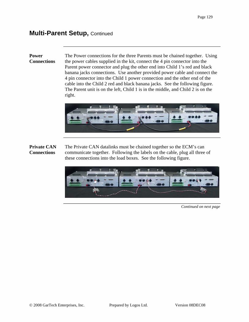
Page 129
© 2008 GarTech Enterprises, Inc. Prepared by Logos Ltd. Version 08DEC08
Multi-Parent Setup, Continued
Power Connections
The Power connections for the three Parents must be chained together. Using the power cables supplied in the kit, connect the 4 pin connector into the Parent power connector and plug the other end into Child 1’s red and black banana jacks connections. Use another provided power cable and connect the 4 pin connector into the Child 1 power connection and the other end of the cable into the Child 2 red and black banana jacks. See the following figure. The Parent unit is on the left, Child 1 is in the middle, and Child 2 is on the right.
Private CAN Connections
The Private CAN datalinks must be chained together so the ECM’s can communicate together. Following the labels on the cable, plug all three of these connections into the load boxes. See the following figure.
Continued on next page

Page 130
© 2008 GarTech Enterprises, Inc. Prepared by Logos Ltd. Version 08DEC08
Multi-Parent Setup, Continued
Public CAN Connections
The Public CAN datalinks must be chained together so the LUIS GUI can send data to each unit. Notice there is a loose connector on the left end of the picture which is used to connect the LUIS PC to the system. The Sidecar-to-Parent Jumpers must also be in place. Following the labels on the cables, plug all three connections in as shown.
Special I/O Connections
There are a few I/O items that need to be chained directly from the cables that connect LUIS to the ECM. These connections are clearly marked and have a 6 pin Deutsch connector to join them together. On the Child 1 and Child 2 cables, the 6 pin connector will have to be disconnected and then reconnected into the provided cables.
Continued on next page

Page 131
© 2008 GarTech Enterprises, Inc. Prepared by Logos Ltd. Version 08DEC08
Multi-Parent Setup, Continued
All Connections
The following figure shows all of the connections needed to make Parent units function for Multi-Module setups.


![A.I. Enterprises Ltd. and A.I. Enterprises Ltd. et …...[2014] 1 R.C.S. A.I. ENTERPRISES c. BRAM ENTERPRISES 177 A.I. Enterprises Ltd. et Alan Schelew Appelants c. Bram Enterprises](https://static.fdocuments.us/doc/165x107/5e918dac94e60f42b949e30a/ai-enterprises-ltd-and-ai-enterprises-ltd-et-2014-1-rcs-ai-enterprises.jpg)