Gar Chai Wong Basil Spence 2014
20
Pictures in the Park Betwixt and Between 1 Basil spence Flood report Gar Chai Wong Group 23
-
Upload
garrick-wong -
Category
Documents
-
view
17 -
download
2
Transcript of Gar Chai Wong Basil Spence 2014
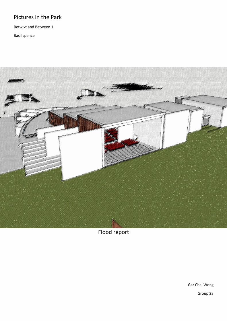
Pictures in the Park
Betwixt and Between 1
Basil spence
Flood report
Gar Chai Wong
Group 23
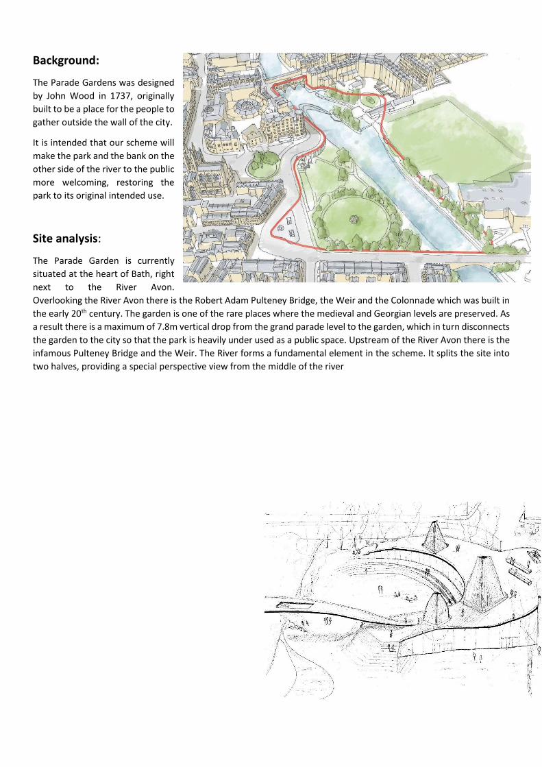
Background:
The Parade Gardens was designed
by John Wood in 1737, originally
built to be a place for the people to
gather outside the wall of the city.
It is intended that our scheme will
make the park and the bank on the
other side of the river to the public
more welcoming, restoring the
park to its original intended use.
Site analysis:
The Parade Garden is currently
situated at the heart of Bath, right
next to the River Avon.
Overlooking the River Avon there is the Robert Adam Pulteney Bridge, the Weir and the Colonnade which was built in
the early 20th century. The garden is one of the rare places where the medieval and Georgian levels are preserved. As
a result there is a maximum of 7.8m vertical drop from the grand parade level to the garden, which in turn disconnects
the garden to the city so that the park is heavily under used as a public space. Upstream of the River Avon there is the
infamous Pulteney Bridge and the Weir. The River forms a fundamental element in the scheme. It splits the site into
two halves, providing a special perspective view from the middle of the river
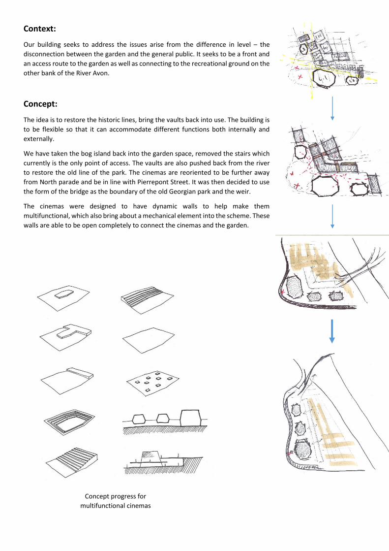
Context:
Our building seeks to address the issues arise from the difference in level – the
disconnection between the garden and the general public. It seeks to be a front and
an access route to the garden as well as connecting to the recreational ground on the
other bank of the River Avon.
Concept:
The idea is to restore the historic lines, bring the vaults back into use. The building is
to be flexible so that it can accommodate different functions both internally and
externally.
We have taken the bog island back into the garden space, removed the stairs which
currently is the only point of access. The vaults are also pushed back from the river
to restore the old line of the park. The cinemas are reoriented to be further away
from North parade and be in line with Pierrepont Street. It was then decided to use
the form of the bridge as the boundary of the old Georgian park and the weir.
The cinemas were designed to have dynamic walls to help make them
multifunctional, which also bring about a mechanical element into the scheme. These
walls are able to be open completely to connect the cinemas and the garden.
Concept progress for
multifunctional cinemas
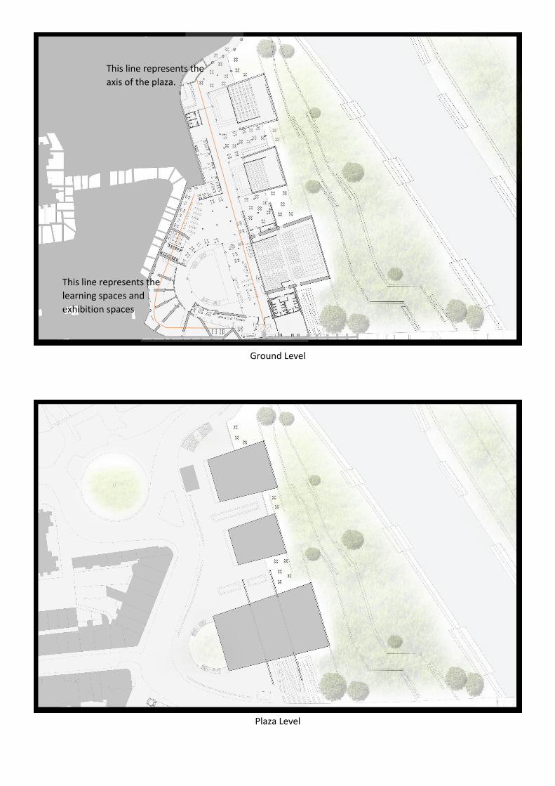
Ground Level
Plaza Level
This line represents the
learning spaces and
exhibition spaces
This line represents the
axis of the plaza.
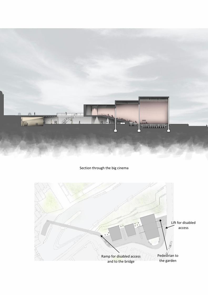
Section through the big cinema
Pedestrian to
the garden
Lift for disabled
access
Ramp for disabled access
and to the bridge
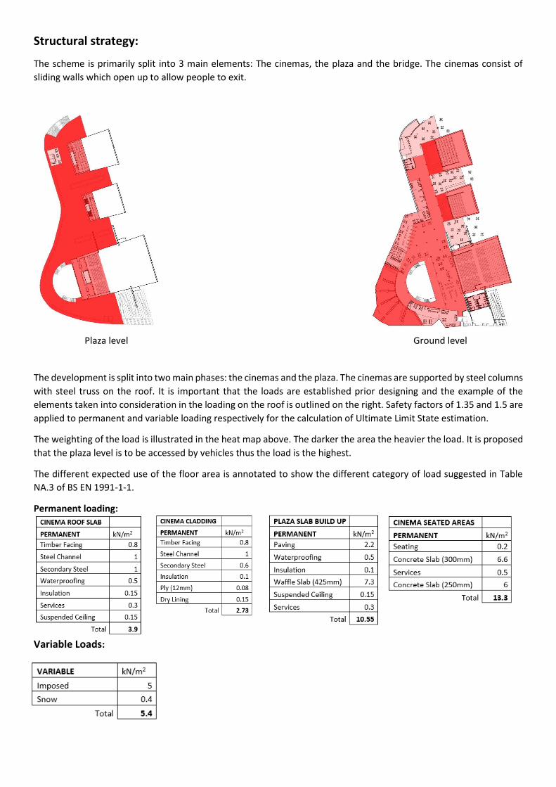
Structural strategy:
The scheme is primarily split into 3 main elements: The cinemas, the plaza and the bridge. The cinemas consist of
sliding walls which open up to allow people to exit.
The development is split into two main phases: the cinemas and the plaza. The cinemas are supported by steel columns
with steel truss on the roof. It is important that the loads are established prior designing and the example of the
elements taken into consideration in the loading on the roof is outlined on the right. Safety factors of 1.35 and 1.5 are
applied to permanent and variable loading respectively for the calculation of Ultimate Limit State estimation.
The weighting of the load is illustrated in the heat map above. The darker the area the heavier the load. It is proposed
that the plaza level is to be accessed by vehicles thus the load is the highest.
The different expected use of the floor area is annotated to show the different category of load suggested in Table
NA.3 of BS EN 1991-1-1.
Permanent loading:
Variable Loads:
CATEGORY EXAMPLE qk
(kN/m2)
C11 Café / Restaurant 2.00
B1 Offices / General 2.50
C13 Classrooms 3.00
C21 Fixed Seating Area 4.00
C33 Crowded Corridor / Circulation 4.00
C39 Exhibition Space 4.00
C5 High Crowd Load 5.00
C41 Studio 5.00
Plaza level Ground level
Wind Load:
The cinema is only supported by the truss and there is no lateral bracing in
that direction, it is required to carry out detail analysis on the impacts the
wind puts on the structure. For ease of calculation it is modelled with a point
load acting along with width and on the top of the wall
Load Combination:
𝑃𝑒𝑟𝑚𝑎𝑛𝑒𝑛𝑡 + 𝐼𝑚𝑝𝑜𝑠𝑒𝑑 + 𝑆𝑛𝑜𝑤
𝑃𝑒𝑟𝑚𝑎𝑛𝑒𝑛𝑡 + 𝑖𝑚𝑝𝑜𝑠𝑒𝑑 + 𝑆𝑛𝑜𝑤 + 𝑊𝑖𝑛𝑑
𝑃𝑒𝑟𝑚𝑎𝑛𝑒𝑛𝑡 + 𝑖𝑚𝑝𝑜𝑠𝑒𝑑 + 𝑊𝑖𝑛𝑑
𝑃𝑒𝑟𝑚𝑎𝑛𝑒𝑛𝑡 + 𝐼𝑚𝑝𝑜𝑠𝑒𝑑
The worst loading combination is incorporated into the design of the structural members It is estimated that the
steel columns will carry 719kN and the concrete columns will carry 1366kN.
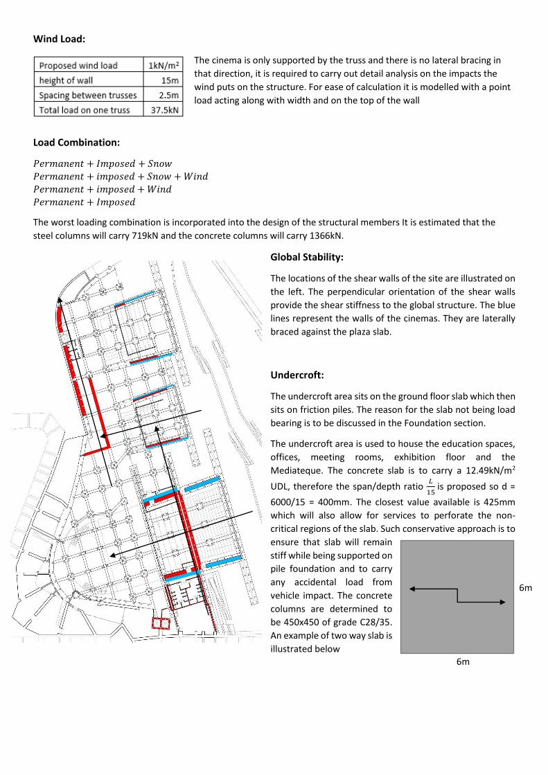
Global Stability:
The locations of the shear walls of the site are illustrated on
the left. The perpendicular orientation of the shear walls
provide the shear stiffness to the global structure. The blue
lines represent the walls of the cinemas. They are laterally
braced against the plaza slab.
Undercroft:
The undercroft area sits on the ground floor slab which then
sits on friction piles. The reason for the slab not being load
bearing is to be discussed in the Foundation section.
The undercroft area is used to house the education spaces,
offices, meeting rooms, exhibition floor and the
Mediateque. The concrete slab is to carry a 12.49kN/m2
UDL, therefore the span/depth ratio 𝐿
15 is proposed so d =
6000/15 = 400mm. The closest value available is 425mm
which will also allow for services to perforate the non-
critical regions of the slab. Such conservative approach is to
ensure that slab will remain
stiff while being supported on
pile foundation and to carry
any accidental load from
vehicle impact. The concrete
columns are determined to
be 450x450 of grade C28/35.
An example of two way slab is
illustrated below
6m
6m
Utilisation of existing vaults
The vaults that currently exist beneath the bog island are left vacant. It is our aim to rejuvenate the vaults and use
them to our advantage. The vaults were built Georgian in arch form, arches are very efficient form of structure to
support very high loads, usually the strength comes with greater compressive load but it is not ideal to put a void in
the wall of a vault as it disrupt the load path which compromises its strength. On the other hand we are restricting the
vehicle traffic on top of the vaults by redirecting the road back to its original shape hundreds of years ago. Therefore
it is proposed that the vaults will be closely monitored during the construction phase on the propagation of cracks and
differential settlements.
Cinema:
The dimension of the big cinema is: 44m x 25m x 15m, it consists of 3 components separated by sliding walls which
will be closed to create three smaller cinemas of seating capacity 250, 200 and 300 respectively.
The larger part of the cinema is to be used as a multifunctional room which can act as a theatre, lecture room or dance
studio etc. To allow for this flexibility the seats are operated on hydraulic jacks which can be lowered to provide a flat
surface or to a preferred arrangement.
The walls sit on rails and operated by motors. They are vertical steel cantilever with the largest one spanning from
3.8m below, up 15m above ground level. The doors are independent of the cinema therefore they do not take any
vertical load apart from their self-weight. However the outermost wall does suffer high wind loading as it being the
façade thus this has to be checked to ensure integrity.
Dynamic façade:
The structure of the wall is to be modelled as a cantilever with two supports. The
𝑀𝑚𝑎𝑥 =𝑤𝑙2
2=
12∗14.52
2= 1261.5𝑘𝑁𝑚 Assuming the use of high grade S355 steel in fabrication, a target value for the
second moment of area was then found and a reasonable section formed of a two 16mmsteel plates with 16mm
stiffeners at 500mm c/c.
The resulting performance of this section means a maximum compressive stress of 15.94N/mm2and moment capacity
of
A simple plate-buckling check was then carried out on an unstiffened region of the compression plate
𝜎𝑐𝑟 =𝜋2𝐸𝑡2
12(1−𝑣2)𝑏2
𝑎
𝑏=
500
500= 1 ∴ 𝑘 = 4
𝜎𝑐𝑟 =𝜋2∗200000∗162
12(1−0.282)∗5002 = 731𝑁/𝑚𝑚2 > 15.94N/mm2 ∴ 𝑜𝑘
The cinema is held up by steel trusses of grade S355 spanning across the width, 25m and spaced 2.5m apart. The truss
consists of 5 diagonal members in each direction. Since the cinema is only braced on the plaza slab along the width of
the truss it needs resist the lateral load. However it is not ideal to transfer moments to the ground since the piles and
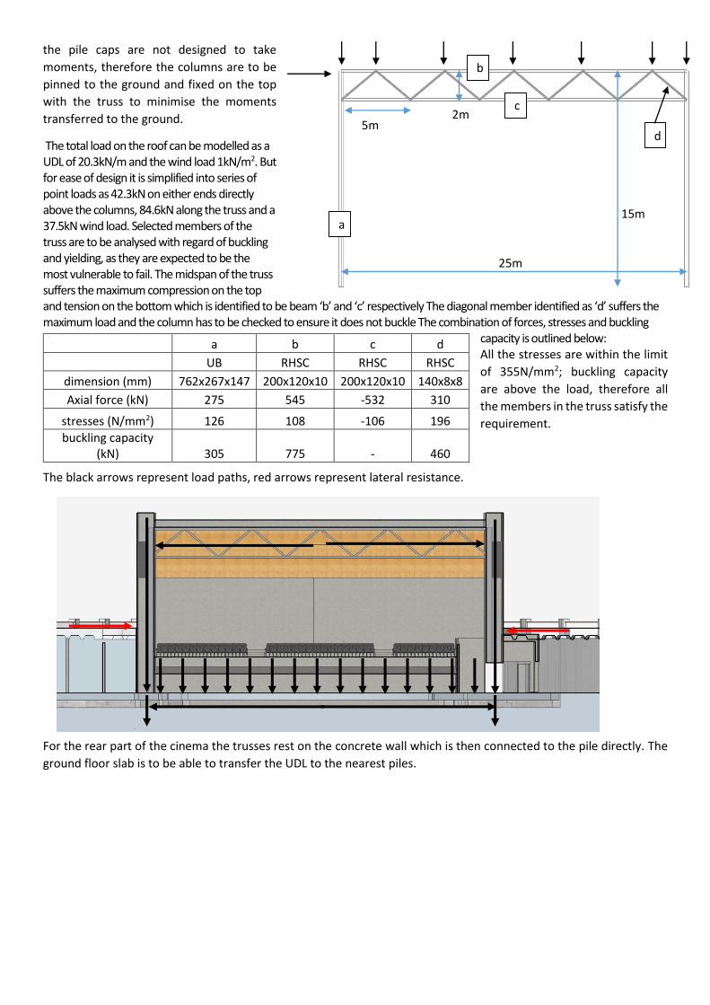
the pile caps are not designed to take
moments, therefore the columns are to be
pinned to the ground and fixed on the top
with the truss to minimise the moments
transferred to the ground.
The total load on the roof can be modelled as a UDL of 20.3kN/m and the wind load 1kN/m2. But for ease of design it is simplified into series of point loads as 42.3kN on either ends directly above the columns, 84.6kN along the truss and a 37.5kN wind load. Selected members of the truss are to be analysed with regard of buckling and yielding, as they are expected to be the most vulnerable to fail. The midspan of the truss suffers the maximum compression on the top and tension on the bottom which is identified to be beam ‘b’ and ‘c’ respectively The diagonal member identified as ‘d’ suffers the maximum load and the column has to be checked to ensure it does not buckle The combination of forces, stresses and buckling
capacity is outlined below: All the stresses are within the limit
of 355N/mm2; buckling capacity
are above the load, therefore all
the members in the truss satisfy the
requirement.
The black arrows represent load paths, red arrows represent lateral resistance.
For the rear part of the cinema the trusses rest on the concrete wall which is then connected to the pile directly. The
ground floor slab is to be able to transfer the UDL to the nearest piles.
a b c d
UB RHSC RHSC RHSC
dimension (mm) 762x267x147 200x120x10 200x120x10 140x8x8
Axial force (kN) 275 545 -532 310
stresses (N/mm2) 126 108 -106 196
buckling capacity (kN) 305 775 - 460
d
c
b
a 15m
25m
5m 2m
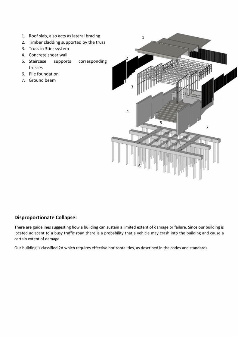
1. Roof slab, also acts as lateral bracing
2. Timber cladding supported by the truss
3. Truss in 3tier system
4. Concrete shear wall
5. Staircase supports corresponding
trusses
6. Pile foundation
7. Ground beam
Disproportionate Collapse:
There are guidelines suggesting how a building can sustain a limited extent of damage or failure. Since our building is
located adjacent to a busy traffic road there is a probability that a vehicle may crash into the building and cause a
certain extent of damage.
Our building is classified 2A which requires effective horizontal ties, as described in the codes and standards
6
4
2
1
3
5 7
Foundation:
Site investigation:
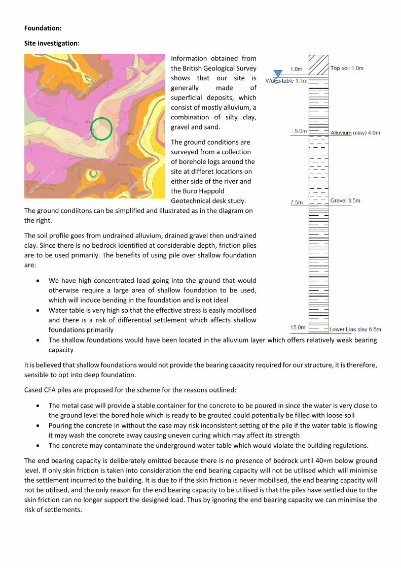
Information obtained from
the British Geological Survey
shows that our site is
generally made of
superficial deposits, which
consist of mostly alluvium, a
combination of silty clay,
gravel and sand.
The ground conditions are
surveyed from a collection
of borehole logs around the
site at differet locations on
either side of the river and
the Buro Happold
Geotechnical desk study.
The ground condiitons can be simplified and illustrated as in the diagram on
the right.
The soil profile goes from undrained alluvium, drained gravel then undrained
clay. Since there is no bedrock identified at considerable depth, friction piles
are to be used primarily. The benefits of using pile over shallow foundation
are:
We have high concentrated load going into the ground that would
otherwise require a large area of shallow foundation to be used,
which will induce bending in the foundation and is not ideal
Water table is very high so that the effective stress is easily mobilised
and there is a risk of differential settlement which affects shallow
foundations primarily
The shallow foundations would have been located in the alluvium layer which offers relatively weak bearing
capacity
It is believed that shallow foundations would not provide the bearing capacity required for our structure, it is therefore,
sensible to opt into deep foundation.
Cased CFA piles are proposed for the scheme for the reasons outlined:
The metal case will provide a stable container for the concrete to be poured in since the water is very close to
the ground level the bored hole which is ready to be grouted could potentially be filled with loose soil
Pouring the concrete in without the case may risk inconsistent setting of the pile if the water table is flowing
it may wash the concrete away causing uneven curing which may affect its strength
The concrete may contaminate the underground water table which would violate the building regulations.
The end bearing capacity is deliberately omitted because there is no presence of bedrock until 40+m below ground
level. If only skin friction is taken into consideration the end bearing capacity will not be utilised which will minimise
the settlement incurred to the building. It is due to if the skin friction is never mobilised, the end bearing capacity will
not be utilised, and the only reason for the end bearing capacity to be utilised is that the piles have settled due to the
skin friction can no longer support the designed load. Thus by ignoring the end bearing capacity we can minimise the
risk of settlements.
Special permissions are to be sought for pile works exceeding 15m below ground,
therefore 15m is to be used as the depth of the piles. The calculations for the bearing
capacity is outlined below:
𝑄𝑢 = 𝑄𝑠 + 𝑄𝑏 𝑎𝑛𝑑 𝑄𝑏𝑖𝑠 𝑖𝑔𝑛𝑜𝑟𝑒𝑑
𝑄𝑠 = 𝑞𝑠𝐴𝑠
𝑞𝑠 = {𝛼𝜏𝑢(𝑎𝑣𝑒) 𝑓𝑜𝑟 𝑢𝑛𝑑𝑟𝑎𝑖𝑛𝑒𝑑 𝑙𝑎𝑦𝑒𝑟
𝜎′𝑣𝐾𝑠𝑡𝑎𝑛𝛿′ 𝑓𝑜𝑟 𝑑𝑟𝑎𝑖𝑛𝑒𝑑 𝑙𝑎𝑦𝑒𝑟
Several assumptions are made for the calculation of the bearing capacity:
Shear strength of the alluvium = 100N/mm2
Kstanδ = 0.35
Shear strength for clay = 125N/mm2
The table on the right shows the different capacity each layer gives. The total Qs sums to 597.4kN per pile. This capacity
is not factored since it is not logical to put safety factors on our assumptions on the soil properties. Should the soil
parameters are obtained from field test safety factors can be applied to them but in this case it is more viable to use
factored load and normal bearing capacity.
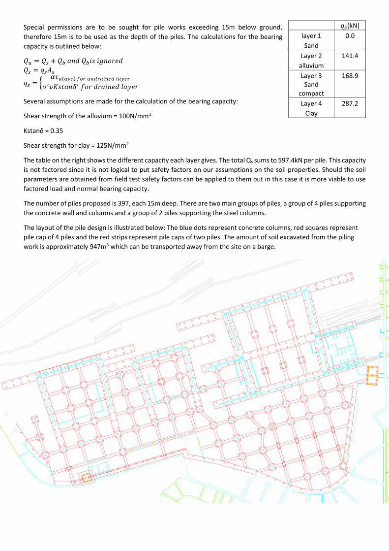
The number of piles proposed is 397, each 15m deep. There are two main groups of piles, a group of 4 piles supporting
the concrete wall and columns and a group of 2 piles supporting the steel columns.
The layout of the pile design is illustrated below: The blue dots represent concrete columns, red squares represent
pile cap of 4 piles and the red strips represent pile caps of two piles. The amount of soil excavated from the piling
work is approximately 947m3 which can be transported away from the site on a barge.
𝑞𝑠(kN)
layer 1 0.0
Sand
Layer 2 141.4
alluvium
Layer 3 168.9 Sand
compact
Layer 4 287.2
Clay
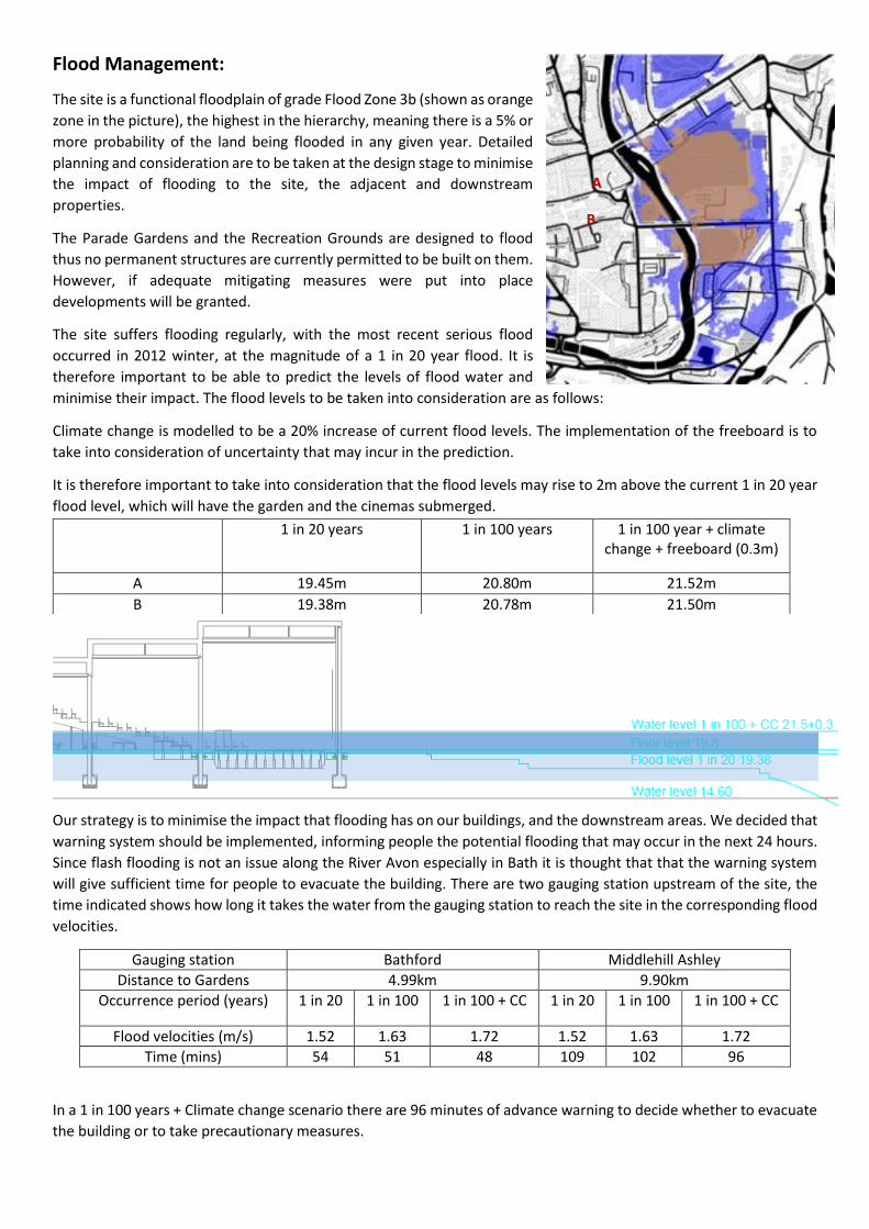
Flood Management:
The site is a functional floodplain of grade Flood Zone 3b (shown as orange
zone in the picture), the highest in the hierarchy, meaning there is a 5% or
more probability of the land being flooded in any given year. Detailed
planning and consideration are to be taken at the design stage to minimise
the impact of flooding to the site, the adjacent and downstream
properties.
The Parade Gardens and the Recreation Grounds are designed to flood
thus no permanent structures are currently permitted to be built on them.
However, if adequate mitigating measures were put into place
developments will be granted.
The site suffers flooding regularly, with the most recent serious flood
occurred in 2012 winter, at the magnitude of a 1 in 20 year flood. It is
therefore important to be able to predict the levels of flood water and
minimise their impact. The flood levels to be taken into consideration are as follows:
Climate change is modelled to be a 20% increase of current flood levels. The implementation of the freeboard is to
take into consideration of uncertainty that may incur in the prediction.
It is therefore important to take into consideration that the flood levels may rise to 2m above the current 1 in 20 year
flood level, which will have the garden and the cinemas submerged.
Our strategy is to minimise the impact that flooding has on our buildings, and the downstream areas. We decided that
warning system should be implemented, informing people the potential flooding that may occur in the next 24 hours.
Since flash flooding is not an issue along the River Avon especially in Bath it is thought that that the warning system
will give sufficient time for people to evacuate the building. There are two gauging station upstream of the site, the
time indicated shows how long it takes the water from the gauging station to reach the site in the corresponding flood
velocities.
Gauging station Bathford Middlehill Ashley
Distance to Gardens 4.99km 9.90km
Occurrence period (years) 1 in 20 1 in 100 1 in 100 + CC 1 in 20 1 in 100 1 in 100 + CC
Flood velocities (m/s) 1.52 1.63 1.72 1.52 1.63 1.72
Time (mins) 54 51 48 109 102 96
In a 1 in 100 years + Climate change scenario there are 96 minutes of advance warning to decide whether to evacuate
the building or to take precautionary measures.
1 in 20 years 1 in 100 years 1 in 100 year + climate change + freeboard (0.3m)
A 19.45m 20.80m 21.52m
B 19.38m 20.78m 21.50m
A
B
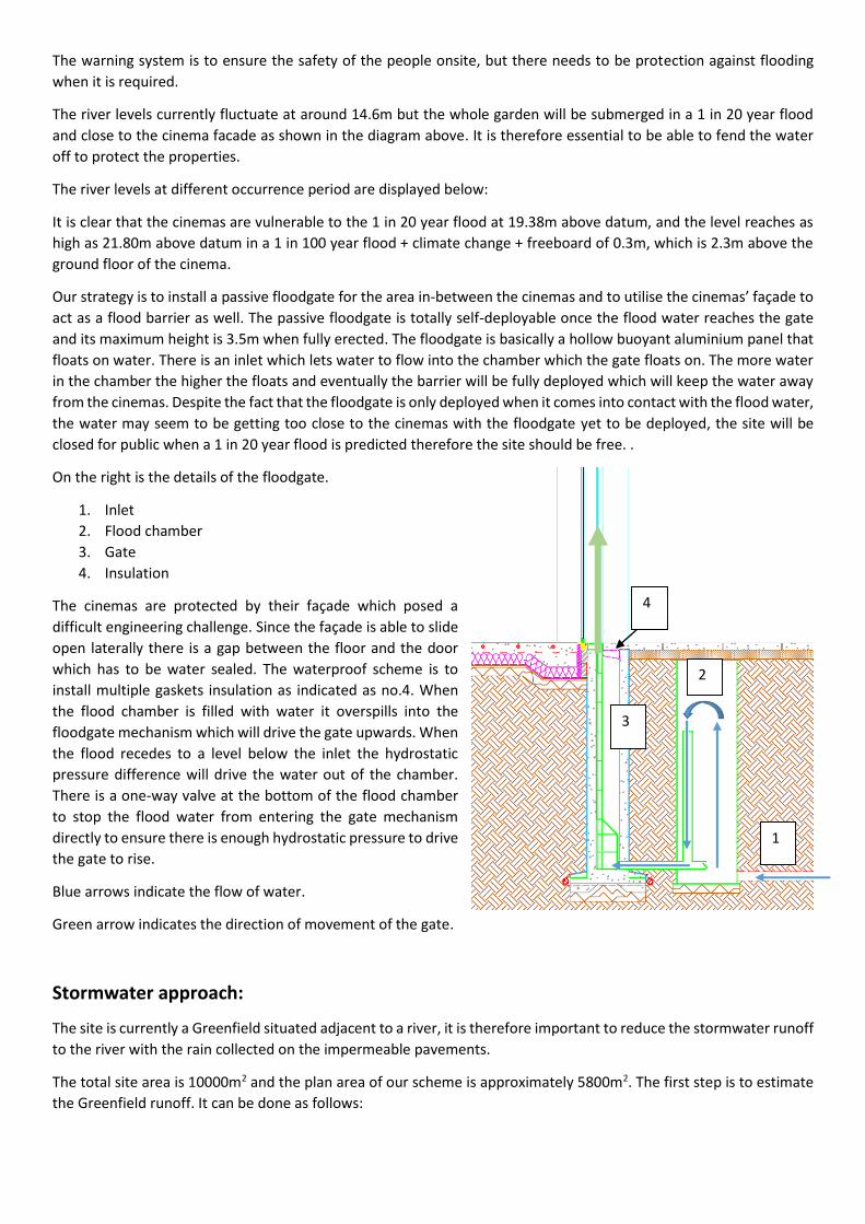
The warning system is to ensure the safety of the people onsite, but there needs to be protection against flooding
when it is required.
The river levels currently fluctuate at around 14.6m but the whole garden will be submerged in a 1 in 20 year flood
and close to the cinema facade as shown in the diagram above. It is therefore essential to be able to fend the water
off to protect the properties.
The river levels at different occurrence period are displayed below:
It is clear that the cinemas are vulnerable to the 1 in 20 year flood at 19.38m above datum, and the level reaches as
high as 21.80m above datum in a 1 in 100 year flood + climate change + freeboard of 0.3m, which is 2.3m above the
ground floor of the cinema.
Our strategy is to install a passive floodgate for the area in-between the cinemas and to utilise the cinemas’ façade to
act as a flood barrier as well. The passive floodgate is totally self-deployable once the flood water reaches the gate
and its maximum height is 3.5m when fully erected. The floodgate is basically a hollow buoyant aluminium panel that
floats on water. There is an inlet which lets water to flow into the chamber which the gate floats on. The more water
in the chamber the higher the floats and eventually the barrier will be fully deployed which will keep the water away
from the cinemas. Despite the fact that the floodgate is only deployed when it comes into contact with the flood water,
the water may seem to be getting too close to the cinemas with the floodgate yet to be deployed, the site will be
closed for public when a 1 in 20 year flood is predicted therefore the site should be free. .
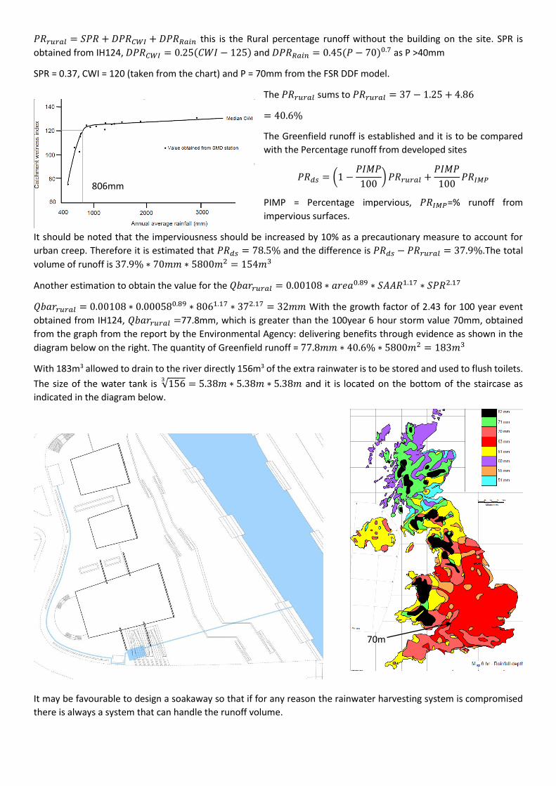
On the right is the details of the floodgate.
1. Inlet
2. Flood chamber
3. Gate
4. Insulation
The cinemas are protected by their façade which posed a
difficult engineering challenge. Since the façade is able to slide
open laterally there is a gap between the floor and the door
which has to be water sealed. The waterproof scheme is to
install multiple gaskets insulation as indicated as no.4. When
the flood chamber is filled with water it overspills into the
floodgate mechanism which will drive the gate upwards. When
the flood recedes to a level below the inlet the hydrostatic
pressure difference will drive the water out of the chamber.
There is a one-way valve at the bottom of the flood chamber
to stop the flood water from entering the gate mechanism
directly to ensure there is enough hydrostatic pressure to drive
the gate to rise.
Blue arrows indicate the flow of water.
Green arrow indicates the direction of movement of the gate.
Stormwater approach:
The site is currently a Greenfield situated adjacent to a river, it is therefore important to reduce the stormwater runoff
to the river with the rain collected on the impermeable pavements.
The total site area is 10000m2 and the plan area of our scheme is approximately 5800m2. The first step is to estimate
the Greenfield runoff. It can be done as follows:
2
1
4
3
𝑃𝑅𝑟𝑢𝑟𝑎𝑙 = 𝑆𝑃𝑅 + 𝐷𝑃𝑅𝐶𝑊𝐼 + 𝐷𝑃𝑅𝑅𝑎𝑖𝑛 this is the Rural percentage runoff without the building on the site. SPR is
obtained from IH124, 𝐷𝑃𝑅𝐶𝑊𝐼 = 0.25(𝐶𝑊𝐼 − 125) and 𝐷𝑃𝑅𝑅𝑎𝑖𝑛 = 0.45(𝑃 − 70)0.7 as P >40mm
SPR = 0.37, CWI = 120 (taken from the chart) and P = 70mm from the FSR DDF model.
The 𝑃𝑅𝑟𝑢𝑟𝑎𝑙 sums to 𝑃𝑅𝑟𝑢𝑟𝑎𝑙 = 37 − 1.25 + 4.86
= 40.6%
The Greenfield runoff is established and it is to be compared
with the Percentage runoff from developed sites
𝑃𝑅𝑑𝑠 = (1 −𝑃𝐼𝑀𝑃
100) 𝑃𝑅𝑟𝑢𝑟𝑎𝑙 +
𝑃𝐼𝑀𝑃
100𝑃𝑅𝐼𝑀𝑃
PIMP = Percentage impervious, 𝑃𝑅𝐼𝑀𝑃=% runoff from
impervious surfaces.
It should be noted that the imperviousness should be increased by 10% as a precautionary measure to account for
urban creep. Therefore it is estimated that 𝑃𝑅𝑑𝑠 = 78.5% and the difference is 𝑃𝑅𝑑𝑠 − 𝑃𝑅𝑟𝑢𝑟𝑎𝑙 = 37.9%.The total
volume of runoff is 37.9% ∗ 70𝑚𝑚 ∗ 5800𝑚2 = 154𝑚3
Another estimation to obtain the value for the 𝑄𝑏𝑎𝑟𝑟𝑢𝑟𝑎𝑙 = 0.00108 ∗ 𝑎𝑟𝑒𝑎0.89 ∗ 𝑆𝐴𝐴𝑅1.17 ∗ 𝑆𝑃𝑅2.17
𝑄𝑏𝑎𝑟𝑟𝑢𝑟𝑎𝑙 = 0.00108 ∗ 0.000580.89 ∗ 8061.17 ∗ 372.17 = 32𝑚𝑚 With the growth factor of 2.43 for 100 year event
obtained from IH124, 𝑄𝑏𝑎𝑟𝑟𝑢𝑟𝑎𝑙 =77.8mm, which is greater than the 100year 6 hour storm value 70mm, obtained
from the graph from the report by the Environmental Agency: delivering benefits through evidence as shown in the
diagram below on the right. The quantity of Greenfield runoff = 77.8𝑚𝑚 ∗ 40.6% ∗ 5800𝑚2 = 183𝑚3
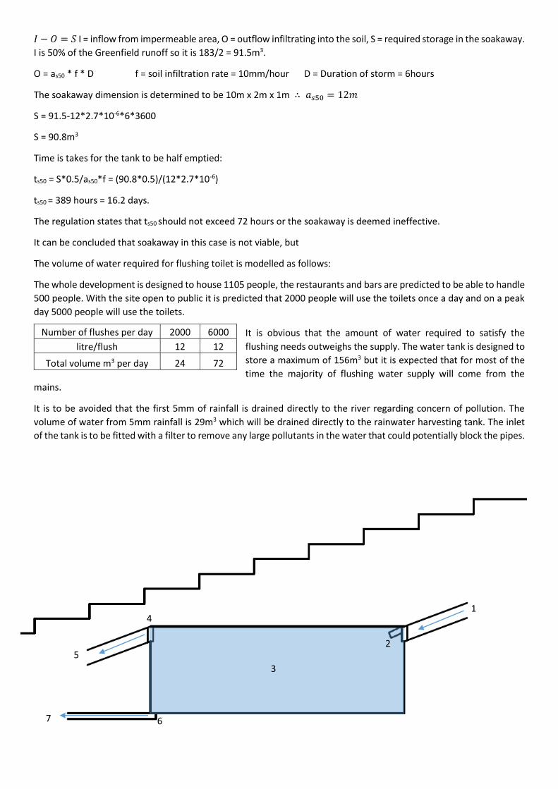
With 183m3 allowed to drain to the river directly 156m3 of the extra rainwater is to be stored and used to flush toilets.
The size of the water tank is √1563
= 5.38𝑚 ∗ 5.38𝑚 ∗ 5.38𝑚 and it is located on the bottom of the staircase as
indicated in the diagram below.
It may be favourable to design a soakaway so that if for any reason the rainwater harvesting system is compromised
there is always a system that can handle the runoff volume.
806mm
70m
m
𝐼 − 𝑂 = 𝑆 I = inflow from impermeable area, O = outflow infiltrating into the soil, S = required storage in the soakaway.
I is 50% of the Greenfield runoff so it is 183/2 = 91.5m3.
O = as50 * f * D f = soil infiltration rate = 10mm/hour D = Duration of storm = 6hours
The soakaway dimension is determined to be 10m x 2m x 1m ∴ 𝑎𝑠50 = 12𝑚
S = 91.5-12*2.7*10-6*6*3600
S = 90.8m3
Time is takes for the tank to be half emptied:
ts50 = S*0.5/as50*f = (90.8*0.5)/(12*2.7*10-6)
ts50 = 389 hours = 16.2 days.
The regulation states that ts50 should not exceed 72 hours or the soakaway is deemed ineffective.
It can be concluded that soakaway in this case is not viable, but
The volume of water required for flushing toilet is modelled as follows:
The whole development is designed to house 1105 people, the restaurants and bars are predicted to be able to handle
500 people. With the site open to public it is predicted that 2000 people will use the toilets once a day and on a peak
day 5000 people will use the toilets.
It is obvious that the amount of water required to satisfy the
flushing needs outweighs the supply. The water tank is designed to
store a maximum of 156m3 but it is expected that for most of the
time the majority of flushing water supply will come from the
mains.
It is to be avoided that the first 5mm of rainfall is drained directly to the river regarding concern of pollution. The
volume of water from 5mm rainfall is 29m3 which will be drained directly to the rainwater harvesting tank. The inlet
of the tank is to be fitted with a filter to remove any large pollutants in the water that could potentially block the pipes.
Number of flushes per day 2000 6000
litre/flush 12 12
Total volume m3 per day 24 72
4
3
2
1
6
5
7
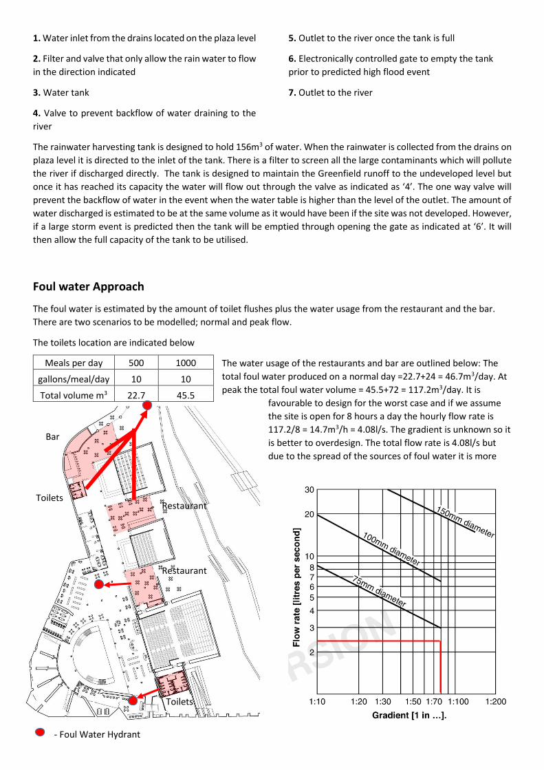
- Foul Water Hydrant
1. Water inlet from the drains located on the plaza level
2. Filter and valve that only allow the rain water to flow
in the direction indicated
3. Water tank
4. Valve to prevent backflow of water draining to the
river
5. Outlet to the river once the tank is full
6. Electronically controlled gate to empty the tank
prior to predicted high flood event
7. Outlet to the river
The rainwater harvesting tank is designed to hold 156m3 of water. When the rainwater is collected from the drains on
plaza level it is directed to the inlet of the tank. There is a filter to screen all the large contaminants which will pollute
the river if discharged directly. The tank is designed to maintain the Greenfield runoff to the undeveloped level but
once it has reached its capacity the water will flow out through the valve as indicated as ‘4’. The one way valve will
prevent the backflow of water in the event when the water table is higher than the level of the outlet. The amount of
water discharged is estimated to be at the same volume as it would have been if the site was not developed. However,
if a large storm event is predicted then the tank will be emptied through opening the gate as indicated at ‘6’. It will
then allow the full capacity of the tank to be utilised.
Foul water Approach
The foul water is estimated by the amount of toilet flushes plus the water usage from the restaurant and the bar.
There are two scenarios to be modelled; normal and peak flow.
The toilets location are indicated below
The water usage of the restaurants and bar are outlined below: The
total foul water produced on a normal day =22.7+24 = 46.7m3/day. At
peak the total foul water volume = 45.5+72 = 117.2m3/day. It is
favourable to design for the worst case and if we assume
the site is open for 8 hours a day the hourly flow rate is
117.2/8 = 14.7m3/h = 4.08l/s. The gradient is unknown so it
is better to overdesign. The total flow rate is 4.08l/s but
due to the spread of the sources of foul water it is more
Meals per day 500 1000
gallons/meal/day 10 10
Total volume m3 22.7 45.5
Restaurant
Toilets
Bar
Toilets Restaurant
logical to discharge to the nearest hydrants. The scheme is therefore proposed as shown on the left, with the top
hydrant responsible for a restaurant, a bar and a toilet, then each of the other hydrant is responsible for the
corresponding foul water source. It is proposed that the pipe installed is of diameter 75mm. From the chart the
minimum gradient is unspecified but due to the spread of the hydrants the peak flow is now estimated to be 3/5 of
the total peak flow which is 2.5l/s and is well below the limit. The decision is based on the graph shown above,
obtained from Approved Document H, Drainage and waste disposal. The lowest gradient recommended is 1:70
despite there is more capacity to go with a lower gradient, the pipe is designed to be a 75mm diameter pipe.
Exception Test:
Since the site is a grade 3b functional floodplain, developments are only permitted on exceptional circumstances.
Our reasoning for the development of the site are:
The rainfall on the paved area of the site is roughly 5800m2 and the rainwater harvesting system is designed
to handle the storm water runoff in a 1 in 100 year 6-hour storm. Such measure improves the current runoff
volume to the river that it will not exacerbate the flood risk of the downstream properties.
The majority of the site is designed to flood and with the utilisation of the existing vaults and the restoration
of the bog island, the Greenfield areas lost are minimised so is the Greenfield runoff.
The safety of the people onsite against flooding is guaranteed by the implementation of the floodgate and the
advance warning system.
Having taken all of the factors mentioned above it can be concluded that the development of the site will improve the
flood management of the area, and the downstream properties.
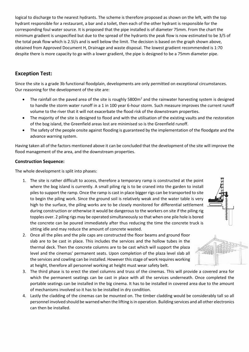
Construction Sequence:
The whole development is split into phases:
1. The site is rather difficult to access, therefore a temporary ramp is constructed at the point
where the bog island is currently. A small piling rig is to be craned into the garden to install
piles to support the ramp. Once the ramp is cast in place bigger rigs can be transported to site
to begin the piling work. Since the ground soil is relatively weak and the water table is very
high to the surface, the piling works are to be closely monitored for differential settlement
during construction or otherwise it would be dangerous to the workers on site if the piling rig
topples over. 2 piling rigs may be operated simultaneously so that when one pile hole is bored
the concrete can be poured immediately after thus reducing the time the concrete truck is
sitting idle and may reduce the amount of concrete wasted.
2. Once all the piles and the pile caps are constructed the floor beams and ground floor
slab are to be cast in place. This includes the services and the hollow tubes in the
thermal deck. Then the concrete columns are to be cast which will support the plaza
level and the cinemas’ permanent seats. Upon completion of the plaza level slab all
the services and cowling can be installed. However this stage of work requires working
at height, therefore all personnel working at height must wear safety belt.
3. The third phase is to erect the steel columns and truss of the cinemas. This will provide a covered area for
which the permanent seatings can be cast in place with all the services underneath. Once completed the
portable seatings can be installed in the big cinema. It has to be installed in covered area due to the amount
of mechanisms involved so it has to be installed in dry condition.
4. Lastly the cladding of the cinemas can be mounted on. The timber cladding would be considerably tall so all
personnel involved should be warned when the lifting is in operation. Building services and all other electronics
can then be installed.
Summer
Winter
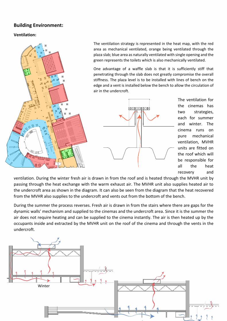
Building Environment:
Ventilation:
The ventilation strategy is represented in the heat map, with the red
area as mechanical ventilated, orange being ventilated through the
plaza slab; blue area as naturally ventilated with single opening and the
green represents the toilets which is also mechanically ventilated.
One advantage of a waffle slab is that it is sufficiently stiff that
penetrating through the slab does not greatly compromise the overall
stiffness. The plaza level is to be installed with lines of bench on the
edge and a vent is installed below the bench to allow the circulation of
air in the undercroft.
The ventilation for
the cinemas has
two strategies,
each for summer
and winter. The
cinema runs on
pure mechanical
ventilation, MVHR
units are fitted on
the roof which will
be responsible for
all the heat
recovery and
ventilation. During the winter fresh air is drawn in from the roof and is heated through the MVHR unit by
passing through the heat exchange with the warm exhaust air. The MVHR unit also supplies heated air to
the undercroft area as shown in the diagram. It can also be seen from the diagram that the heat recovered
from the MVHR also supplies to the undercroft and vents out from the bottom of the bench.
During the summer the process reverses. Fresh air is drawn in from the stairs where there are gaps for the
dynamic walls’ mechanism and supplied to the cinemas and the undercroft area. Since it is the summer the
air does not require heating and can be supplied to the cinema instantly. The air is then heated up by the
occupants inside and extracted by the MVHR unit on the roof of the cinema and through the vents in the
undercroft.
Heating:
The thermal comfort of the cinemas is to be achieved by incorporating thermal deck in the design. Thermal
decks are concrete slabs that have hollow tubes spanning the length of the slabs. During winter when heating
is required the warm air recycled by the MVHR is pumped through the hollow tubes in the deck which will
then be absorbed by the concrete thermal mass and re-emit to the surrounding area.
Acoustic:
The acoustic performance of a cinema is of the highest importance. It has to be ensured that the noise from
the external sources will be attenuated sufficiently when it reaches internal area of the cinemas, and vice
versa, the sound from inside the cinemas cannot be heard at the outside. The area of the acoustic panels
required highly depends on their acoustic performances to achieve 0.8 second of reverberation time.
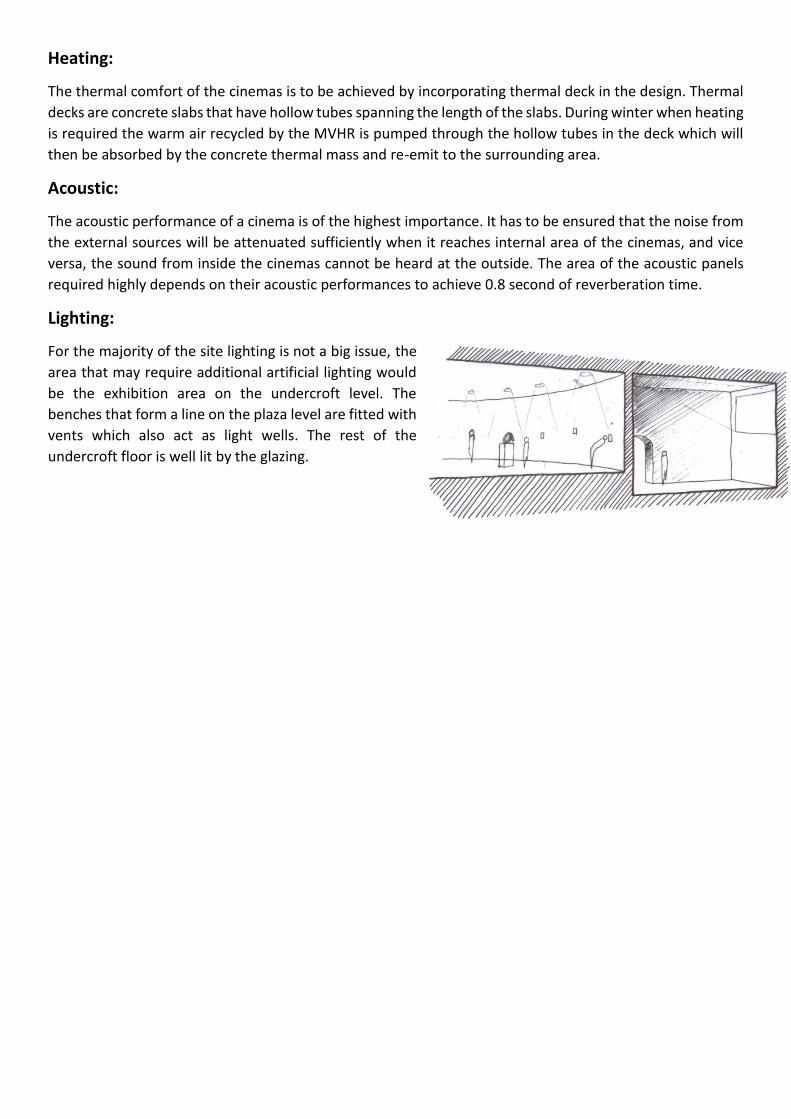
Lighting:
For the majority of the site lighting is not a big issue, the
area that may require additional artificial lighting would
be the exhibition area on the undercroft level. The
benches that form a line on the plaza level are fitted with
vents which also act as light wells. The rest of the
undercroft floor is well lit by the glazing.