gallerY: oil and gas indusTrY aPPliCaTions - · PDF fileANSYSCO SPECIAL ISSUE: OIL AND GAS 21...
4
© 2015 ANSYS, INC. ANSYS ADVANTAGE | SPECIAL ISSUE: OIL AND GAS | 2015 19 APPLICATIONS GALLERY: OIL AND GAS INDUSTRY APPLICATIONS Around the world, oil and gas companies require best-in-class technology to maintain profitabiliy, reliability and safety. By ANSYS Advantage Staff Design, engineering and manufacturing groups within the global energy supply chain span multiple geographies and encompass teams engaged in discovery, drilling, production, storage, transportation, refining and end-use petrochemicals. Each sector faces a broad set of challenges that require solving with different physics, scales and components. ANSYS delivers class-leading software and employs a network of technical experts who work with oil and gas customers around the world. These industry MULTIPHASE PIPE FLOW ANSYS CFD solutions are used throughout the oil and gas industry for subsurface, pipeline, transport, processing and refining applications; almost all these oil and gas applications involve multiphase flows. For example, flashing simulation can be performed using ANSYS Fluent. The images reveal contours of vapor- phase mass fractions at various downstream cross sections. The mass fractions of vaporized hydrocarbons increase with distance downstream from the mixing point. Red is maximum, blue is minimum. professionals operate from regional offices close to energy companies in Houston, Aberdeen, Oslo, Stavanger, Kuala Lumpur, Beijing, Calgary and other locations worldwide. With a network of channel partners and ANSYS industry experts — and a long-standing commitment to the energy industry — ANSYS fosters close relationships with energy industry customers, and provides targeted solutions backed by local service and support. This gallery highlights some recent examples of best-in-class solutions. PREDICTING EQUIPMENT FAILURE DUE TO EROSION Drill cuttings, produced sand and proppants transport reduce the life of equipment, pipelines and downhole tools through erosion. ANSYS solutions can predict erosion due to particulate flow as well as that caused by both impact and rolling at the surfaces. The ANSYS toolkit enables flow modeling of single or multiple fluids that take into account particle size and loadings. A wide array of industry-accepted models is provided to determine erosion rate. Calculations allow for material wear, so geometry is dynamically modified as the material is eroded. The image shows contours of erosion rate on a choke valve.
Transcript of gallerY: oil and gas indusTrY aPPliCaTions - · PDF fileANSYSCO SPECIAL ISSUE: OIL AND GAS 21...
© 2015 ANSYS, INC. ANSYS ADVANTAGE | SPECIAL ISSUE: OIL AND GAS | 2015 19
APPLicATiONs
gallerY: oil and gas indusTrY aPPliCaTionsAround the world, oil and gas companies require best-in-class technology to maintain profitabiliy, reliability and safety.
By ANSYS Advantage Staff
Design, engineering and manufacturing groups within the global energy supply chain span multiple geographies and encompass teams engaged in discovery, drilling, production, storage, transportation, refining and end-use petrochemicals. Each sector faces a broad set of challenges that require solving with different physics, scales and components. ANSYS delivers class-leading software and employs a network of technical experts who work with oil and gas customers around the world. These industry
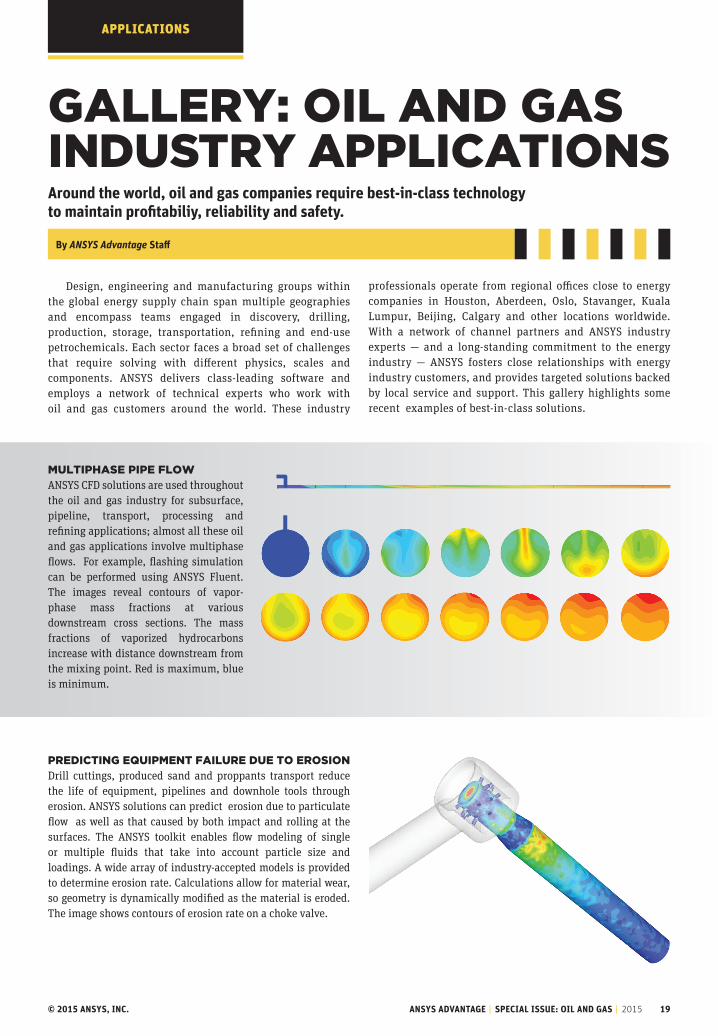
mulTiPhase PiPe FlowANSYS CFD solutions are used throughout the oil and gas industry for subsurface, pipeline, transport, processing and refining applications; almost all these oil and gas applications involve multiphase flows. For example, flashing simulation can be performed using ANSYS Fluent. The images reveal contours of vapor-phase mass fractions at various downstream cross sections. The mass fractions of vaporized hydrocarbons increase with distance downstream from the mixing point. Red is maximum, blue is minimum.
professionals operate from regional offices close to energy companies in Houston, Aberdeen, Oslo, Stavanger, Kuala Lumpur, Beijing, Calgary and other locations worldwide. With a network of channel partners and ANSYS industry experts — and a long-standing commitment to the energy industry — ANSYS fosters close relationships with energy industry customers, and provides targeted solutions backed by local service and support. This gallery highlights some recent examples of best-in-class solutions.
PrediCTing equiPmenT Failure due To erosion Drill cuttings, produced sand and proppants transport reduce the life of equipment, pipelines and downhole tools through erosion. ANSYS solutions can predict erosion due to particulate flow as well as that caused by both impact and rolling at the surfaces. The ANSYS toolkit enables flow modeling of single or multiple fluids that take into account particle size and loadings. A wide array of industry-accepted models is provided to determine erosion rate. Calculations allow for material wear, so geometry is dynamically modified as the material is eroded. The image shows contours of erosion rate on a choke valve.

© 2015 ANSYS, INC. ANSYS ADVANTAGE | SPECIAL ISSUE: OIL AND GAS | 2015 20
APPLicATiONs
weT deCk slamming: irregular sea waves The successful design of an offshore vessel requires that sea wave forces and the motion created by irregular wave slamming are accurately taken into account. Engineers use ANSYS Fluent to study free-surface flows and related sea motions (six degrees of freedom: yaw, roll, pitch) for offshore floating production, storage and offloading units (FPSOs), platforms, and other vessels used for oil and gas drilling, production and transport. Sample results from a CFD study demonstrate two time sequences of peak impact pressure incidence (5,000 metric tons) on a twin-hulled offshore ship.
ComPrehensive mulTiPhYsiCs analYsis oF equiPmenT launCh Accurately simulating the motion and behavior of offshore and subsea structures during equipment launch requires the use of a full set of solutions — including hydrodynamics, fluid mechanics and structural mechanics. ANSYS comprehensive solutions for fluid–mechanical systems simulation help engineers to fully understand and optimize the successful launch of complex equipment.
Recently, results for a fluid–structure interaction approach using ANSYS solutions was demonstrated (OTC-25233-MS)* on a 58-metric-ton subsea manifold. Transient simulations were conducted to calculate fluid forces, which in turn were used to cal-culate the structural response of the manifold through the splash zone. * Fluid–Structure Interaction: Lowering Subsea Structure/Equipment in Splash ZoneDuring Installation D. Jia, Technip and M. Agrawal, ANSYS
CusTomizaTion and engineering ProduCTiviTY Tools ANSYS customers and channel partners develop customized solutions using ANSYS ACT. Within this framework, targeted applications and complete vertical solutions can be created for a problem of interest. One productivity toolkit of interest to the oil and gas industry is a collection of ACT applications developed to follow standard design practices. This oil and gas productivity toolkit contains applications to enable efficient pre- and post-processing of models typical for the industry. Assemblies with a large number of bolts as well as applications that require nonlinear soil stiffness as a bound-ary condition are examples that the toolkit can efficiently handle. Results evaluation based on common standards such as ASME VIII, DNV GL–recommended practices and weld-strength calculations are other simulation tasks that can be accomplished using the productivity toolkit.This toolkit has been developed by ANSYS channel partner EDRMedeso.
oPTimizing hYdroCarbon ProduCTion and uniT develoPmenT CosTs in unConvenTional oil and gas reservoirsEngineers can combine structural mechanics and fluid flow analysis for jointed rocks with sensitivity and parametric analysis to optimize hydraulic fracking. This allows companies to balance an increase in production with unit development costs and will lead to efficient fracking design and stimulation treatment. Using simulation to under-stand factors for hydraulic fracturing performance results in a cost-effective hydraulic fracking strategy and improved production profile for the budget.This information was obtained in partnership with Dynardo GmbH.

ANSYS.COM SPECIAL ISSUE: OIL AND GAS 21
THERMODYNAMIC PHASE CHANGE IN OIL AND GAS PIPELINE AND FACILITIESProduction, transport and refining of crude oil require equipment and processes that control oil components with different thermodynamic properties. Historically, only 1-D flow analysis software accounted for phase equilibrium in multiphase flow equipment. ANSYS customers use 3-D computational fluid dynamics analysis and PVT calculations to account for detailed fluid mechanics and related flow properties for different fluid temperatures and pressures. ANSYS channel partner Grupo SSC developed an applica-tion that determines thermodynamic characteristics of different reservoir fluids. This application matches available experimental data (saturation pressure, density and gas–oil ratios), and it allows prediction of properties when there is no data available. The application is connected to ANSYS CFD software and provides all the PVT information needed to accurately account for fluids properties, enabling more–accurate predictions of phase changes, such as with the vaporization process. This work was performed by Grupo SSC, ANSYS channel partner in Mexico.
COOL-DOWN ANALYSIS OF SUBSEA SEPARATORSDesign of subsea equipment to effectively and reliably operate for long periods of time is challenging. Some of the complexity is derived from understanding multiphase flows and cool-down for each device during a disruption or pause in production. Engineers are seeking to prevent the undesirable formation of hydrates. FMC Technologies engineers in Brazil performed thermal and fluid flow analysis of a three-phase gravitational separator to optimize the design and help determine the cool-down requirement for a temperature range from 55 C to 15 C (hydrate formation temperature) with an external temperature of 4 C (seawater).FMC Technologies in Brazil is supported by ESSS, the ANSYS channel partner for South America. This information was presented at CFDOIL2014.
FLOW ASSURANCE: GAS HYDRATE CHARACTERIZATION Utilizing a combination of species transport and population balance modeling, engineers can perform hydrate formation simulation in oil and gas equipment and pipelines under given pressure, temperature and gas composition conditions. Volumetric and surface-initiated phase change processes are accounted for by including hydrate formation kinetics. This framework enables the use of ANSYS computational fluid dynamics solutions to track hydrate deposition, aggregation and dissociation effects of two-phase flows in oil and gas applications.
NONLINEAR ANALYSIS OF ELASTOMERIC SEALS Downhole packers are critical to ensure a proper seal between different stages of the well; they are often subject to extreme loads and downhole conditions. Real-world wellbore conditions are very difficult to replicate in a laboratory setting, so there is a strong need to simulate the behavior of the packer using numerical tools. ANSYS has a rich library of highly nonlinear material models that replicate the behavior of packers under a variety of conditions. The robustness of the solver allows users to manage the complexity of self-contacts and large geometric distortions.
Courtesy FMC Technologies.
�Volume fraction of gas due to phase change (vaporization) behind a butterfly valve for a 41° API and 60 GOR

22 ANSYS ADVANTAGE | 2015
OPTIMIZING FUEL REFORMERSFuel reformers and cracking furnaces contain a combustion chamber in which heat is generated using burners. This heat is transferred to serpentine tubes carrying process steam. These tubes must uniformly heat the flow for effective cracking. To gain maximum efficiency and eliminate hot spots that can lead to fouling and tube failure, equipment designers must understand the interactions between 3-D combustion in the furnace and 1-D exothermic chemical reaction within the process tubes. ANSYS CFD software uses a channel model to simulate complex reformers and cracker furnaces in less time by coupling the desired 1-D to 3-D reactions in one integrated simulation. The image shows hot gases from the burners providing heat to the process tubes and enabling internal reactions. The ANSYS integrated solution allows engineers to change operating conditions to use the full length of the process tubes for production.
PORO-ELASTIC ANALYSIS: RESERVOIR VERTICAL COMPACTION Reservoir compaction as a result of hydrocarbon production causes surface subsidence, permeability loss and casing failure. Casing crushing, shear and stability (withstanding buckling) are the direct results of subsidence. Subsidence can also lead to the reactivation of faults. ANSYS structural mechanics products offer coupled pore–pressure thermal elements that can be used in the analysis of porous media. ANSYS engineers are assisting oil and gas companies with modeling vertical compaction of reservoir as well as vertical compaction causing damage to a surface facility. Given the right formation properties (assuming saturated porous media), it is possible to calculate pressure distribution in the reservoir as a result of fluid extraction. Although there are typically dozens of variables involved in accurately predicting reservoir behavior, this method is proven to provide valuable insights.
SUBSURFACE EQUIPMENT AND TOOLS IN SAGD Flow control devices (FCDs) are a critical part of production in oil sands operations for steam-assisted gravity drainage (SAGD). Variations on FCD designs can be used for injector and producer wells. One of the key performance parameters is the relationship between pressure drop and flow rates. It is desirable to have designs that do not exhibit large changes in pressure drop with flow changes. This ensures that consistent flow rates are obtained for a large range of conditions present in non-homogeneous reservoirs, helps mitigate flashing and steam production, and assists in controlling erosion. ANSYS CFX was used to perform CFD analyses on Alberta Flux Solutions’ production and injector tool designs. The simulations ensured that the correct pressure drop was obtained at a nominal flow rate. Additional sensitivity studies were conducted to obtain the pressure drop profile over a range of flow rates to help gauge performance relative to other products on the market and differentiate them from competition. Finally, the results guided newer designs and reduced the sensitivity of the FCDs’ performance to manufacturing tolerances. Alberta Flux Solutions is supported by ANSYS channel partner SimuTech Group.
TESTED EXPERIENCE, TRUSTED SOLUTIONS In a recent issue of the EnginSoft Newsletter, from the ANSYS channel partner in Italy, over 20 simulation case studies explore the technology requirements and range of problems that can be solved within the oil and gas industry. This magazine demonstrates how companies worldwide use simulation to understand root–cause failures, improve product reliability, evaluate new designs, and examine recovery concepts for topics including multiple–phase effects, electromechanical effects, particulate motion studies, free–surface flows, rock fractionation, erosion and fluid–structure interaction, thermal stresses, and soil–pipe interaction.
APPLICATIONS
Courtesy Alberta Flux Solutions.
For more information from ANSYS partners, visit the corresponding websites.