Galaxy 3000 - APC by Schneider Electric€¦ · · 2013-05-24Galaxy 3000 10 - 30 kVA LE SAVOIR...
31
Galaxy 3000 10 - 30 kVA LE SAVOIR FAIRE MERLIN GERIN Installation and user manual MGE TM UPSILON TM STS 50, 60 Hz 30A-60A-100A-160A 250A- 400A-630A
Transcript of Galaxy 3000 - APC by Schneider Electric€¦ · · 2013-05-24Galaxy 3000 10 - 30 kVA LE SAVOIR...

34020113EN/AH - Page 1
Galaxy 300010 - 30 kVA
LE SAVOIR FAIRE MERLIN GERIN
Installation and usermanual
MGETM UPSILONTMSTS50, 60 Hz30A-60A-100A-160A 250A-400A-630A

Page 2 - 34020113EN/AH

34020113EN/AH - Page 3
Introduction
Thank you for selecting an APC by Schneider Electric product to protect your electrical equipment.
The MGE™ Upsilon™ STS range has been designed with the upmost care. We recommend that you take the time to readthis manual to take full advantage of the many features of your new equipment.
APC by Schneider Electric pays great attention to the environmental impact of its products. Measures that have madeMGE™ Upsilon™ STS a reference in environmental protection include:◗ the eco-design approach used in product development,◗ production on an industrial site certified ISO 14001,◗ recycling of MGE™ Upsilon™ STS at the end of its service life.
To discover the entire range of APC by Schneider Electric products and the options available for the MGE™
Upsilon™ STS
range, we invite you to visit our web site at www.apc.com or contact your APC by Schneider Electric representative.
All products in the MGETM
UpsilonTM
STS range are protected by patents. They implement original technology not available to competitorsof APC by Schneider Electric.
To take into account evolving standards and technology, equipment may be modified without notice. Indications concerning technicalcharacteristics and dimensions are not binding unless confirmed by APC by Schneider Electric.
This document may be copied only with the written consent of APC by Schneider Electric. Authorised copies must be marked "MGE
TM Upsilon
TM STS Installation and User Manual, no. 3402011300".
Standards
Emc
The STS must be installed in agreement with the IEC 60364 standards family (including IEC 60364-4-41, IEC 60364-4-42and IEC 60364-4-43) and local regulations.
This product is an apparatus answering the Class A requirements as described in the CISPR 11 standard.It is intended to be connected to an installation separated from the public mains by a transformer. It can be connected to thepublic mains (residential installation or any installation having the the same supply mains) only by a professional, insuring thatthe installation requirements are respected.
Page 4 - 34020113EN/AH
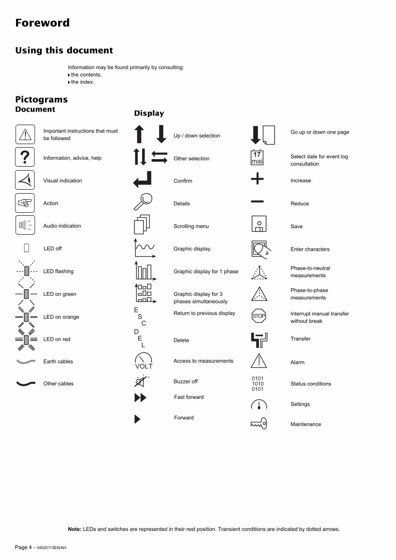
Foreword
Using this document
Important instructions that mustbe followed
Information, advice, help
Visual indication
Action
Audio indication
LED off
PictogramsDocument
Information may be found primarily by consulting:◗ the contents,◗ the index.
Display
LED on orange
LED on red
Note: LEDs and switches are represented in their rest position. Transient conditions are indicated by dotted arrows.
Earth cables
Other cables
LED flashing
LED on green
E S CD E L
VOLT
17
mai
STOP
010110100101
Up / down selection
Other selection
Confirm
Details
Scrolling menu
Return to previous display
Delete
Graphic display
Graphic display for 1 phase
Graphic display for 3phases simultaneously
Access to measurements
Buzzer off
Go up or down one page
Select date for event logconsultation
Increase
Reduce
Save
Enter characters
Phase-to-neutralmeasurements
Phase-to-phasemeasurements
Interrupt manual transferwithout break
Transfer
Alarm
Status conditions
Settings
Maintenance
Fast forward
Forward

34020113EN/AH - Page 5
Contents
1. Presentation
1.1 MGETM UpsilonTM STS 30 - 60 - 100 - 160 - 250 A (cabinet 1400 mm high) .............................. 7
1.2 MGETM UpsilonTM STS 30 - 60 - 100 - 160 - 250 - 400 - 630 A (cabinet 1900 mm high) ........... 7
1.3 Access to control and connections .......................................................................................... 8
MGETM UpsilonTM STS 30 - 60 - 100 - 160 - 250 A (cabinet 1400 mm high) .................................. 8MGETM UpsilonTM STS 30 - 60 - 100 - 160 - 250 - 400 - 630 A (cabinet 1900 mm high) ............... 8
1.4 Man / machine interface ............................................................................................................... 9
1.5 Relay communication card ........................................................................................................ 10
1.6 JBus communication card ......................................................................................................... 10
1.7 MGE SNMP/Web card communication card (optional) ............................................................ 10
1.8 PowerService Telpac communication card (optional) ............................................................. 10
2. Installation
2.1 Positioning .................................................................................................................................. 11
MGETM UpsilonTM STS 30 - 60 - 100 - 160 - 250 A (cabinet 1400 mm high) ................................ 11MGETM UpsilonTM STS 30 - 60 - 100 - 160 - 250 - 400 - 630 A (cabinet 1900 mm high) ............. 11
2.2 Power connections ..................................................................................................................... 12
MGETM UpsilonTM STS 30 to 250 A with input/output: 3 phases + PEN, ...................................... 12MGETM UpsilonTM STS 30 to 250 A with input: 3 phases + PEN, output: 3 phases + PE + Neutral ....................................................................................................................................................... 12MGETM UpsilonTM STS 30 to 250 A with input: 3 phases + PEN, output: 3 phases + PE ............ 13MGETM UpsilonTM STS 30 to 250 A with input/output: 3 phases + PE + Neutral .......................... 13MGETM UpsilonTM STS 30 to 250 A with input/output: 3 phases + PE .......................................... 13MGETM UpsilonTM STS 400 to 630 A with input/output: 3 phases + PEN ..................................... 14MGETM UpsilonTM STS 400 to 630 A with input: 3 phases + PEN, output: 3 phases + PE + Neutral...................................................................................................................................................... 14MGETM UpsilonTM STS 400 to 630 A with input: 3 phases + PEN, output: 3 phases + PE .......... 15MGETM UpsilonTM STS 400 to 630 A with input/output: 3 phases + PE + Neutral ........................ 15MGETM UpsilonTM STS 400 to 630 A with input/output: 3 phases + PE........................................ 15Cable running for cables entering through the top of the Upsilon STS 30 to 250 A cabinet ........ 16
2.3 Connection of the communication cards ................................................................................. 17
2.4 Connection of the JBUS communication card ......................................................................... 17
2.5 Connection of the relay communication card .......................................................................... 18
3. Operation
3.1 Start-up ........................................................................................................................................ 19
3.2 Shutdown..................................................................................................................................... 19
3.3 Normal mode: operation on preferred source S1 .................................................................... 20
Operation on the preferred source ................................................................................................ 20Automatic transfer to the alternate source .................................................................................... 20Manual transfer to the alternate source ........................................................................................ 20Manual transfer to an out-of-phase alternate source .................................................................... 21
3.4 Display screens ........................................................................................................................... 22
3.5 MGETM UpsilonTM STS customization ........................................................................................ 23
3.6 Customization of the relay communication card ..................................................................... 24
4 Maintenance
4.1 Identification of anomalies ......................................................................................................... 25

Page 6 - 34020113EN/AH
Contents
4.2 Transfer to the manual bypass .................................................................................................. 26
5 Environment .....................................................................................................................................27
6 Appendix
6.1 Technical data ............................................................................................................................. 28
Output currents and voltage .......................................................................................................... 28Thermal characteristics ................................................................................................................. 28Noise level .................................................................................................................................... 28Cable sizes ................................................................................................................................... 28Recommended protection devices upstream of Upsilon STS ..................................................... 28Permissible-overload curve ........................................................................................................... 28
6.2 Simplified diagrams .................................................................................................................... 29
Upsilon STS simplified diagram ................................................................................................... 29Simplified diagram of an installation ............................................................................................. 29
6.3 Glossary ....................................................................................................................................... 30
6.4 Index ............................................................................................................................................. 31

34020113EN/AH - Page 7
1. Presentation
1.1 MGETM UpsilonTM STS 30 - 60 - 100 - 160 - 250 A (cabinet 1400 mm high)
1.2 MGETM UpsilonTM STS 30 - 60 - 100 - 160 - 250 - 400 - 630 A(cabinet 1900 mm high)
Height
1400 ±10
Dimensions in mm
Weight in kg
Width
615Depth
565
STS
30 - 60 - 100 A
160 - 250 A
157 kg174 kg
Height
1900 ±10
Dimensions in mm
Width
715Depth
825
Weight in kg
STS
30 - 60 - 100 A
160 - 250 A
400 - 630 A
215 kg225 kg327 kg
Footprint
0.34 m2
Footprint
0.60 m2
Important: correct ventilation
requires at least 250 mm of free
space behind the cabinet.

Page 8 - 34020113EN/AH
1. Presentation
1.3 Access to control and connections
Switch Q1 for Source S1
Circuit breaker Q6 for control electronicspower supply
Switch Q2 for Source S2Communication card cageBypass switch Q1BP for Source S1
Output switch Q3Bypass switch Q2BP for Source S2
Earth bar
Connection cover
Base panels
Adjustable foot pads
MGETM UpsilonTM STS 30 - 60 - 100 - 160 - 250 A (cabinet 1400 mm high)
MGETM UpsilonTM STS 30 - 60 - 100 - 160 - 250 - 400 - 630 A (cabinet 1900 mm high)
Source S2 connection
Output connectionsSource S1 connection
Base panels
Switch Q1 for Source S1Circuit breaker Q4 for control electronicspower supply
1
2
3
5
4
6
7
8
9
12
13
18
14
10
11
16
17
Circuit breaker Q4 for control electronicspower supply
Circuit breaker Q6 for control electronicspower supplySwitch Q2 for Source S2Communication card cageBypass switch Q1BP for Source S1Output switch Q3
Bypass switch Q2BP for Source S2Source S2 connectionOutput connections
Source S1 connectionEarth bar
Connection cover
Adjustable foot pads15
Phases separatorsOpening for cables
Cable way
9
1
2
3
5
4
6
7
8
16
12
13
14
15
10
11
17
18
Cable way
Opening for cablesPhases separators
Only trained and authorized personnel
may work on this product, in regard to
the installation, use or maintenance
operations.
Only trained and authorized personnel
may work on this product, in regard to
the installation, use or maintenance
operations.

34020113EN/AH - Page 9
Q1BP
Q1 Q2
Q2BPQ3
loadcharge
?
Menu
Alarme
Mesures
Etats
Historique
Transfert
Alarme
Mesures
Etats
Historique
Menu
UPS galaxy
deuxième étage, salle 13
UPS galaxy
deuxième étage, salle 14
Source secours
UPS galaxy
deuxième étage, salle 13
Source prioritaire
UPS galaxy
deuxième étage, salle 14
NORMAL OPERATION
I1 17 A I2 9 A I3 2 A
1 KW 6 KVA
PF 0.3
preferred
synchro
UPS 1
= 0°
U12 413 VU23 414 VU31 414 V 50.0 Hz
UPS 2U12 412 VU23 415 VU31 413 V 50.0 Hz
volt
1. Presentation
1.4 Man / machine interface
21
22
23
24
26
25
27
28
29
30
31
32
33
34
35
36
37
38
General alarmGraphic displayFunction buttons
Preferred source S1Manual transfer buttonMenu buttonPreferred source S2Help buttonStatus of switch Q1 (green, red)Status of switch Q2 (green, red)Status of source S1 (green, orange, red)Status of source S2 (green, orange, red)Status of static switch 1 (green, red)Status of static switch 2 (green, red)Status of bypass switch Q2BPStatus of switch Q3Status of bypass switch Q1BPStatus of system output to the load (green,orange, red)

Page 10 - 34020113EN/AH
1 2 3 4 5 6
AB
1. Presentation
1.5 Relay communication card
1.6 JBus communication card
Screws to secure the cover
Card fixing holes
Protection cover
Openings for cables
Output terminal block
Input terminal block
Screws to block cables
41
44
43
42
45
47
46
49
48 RS232 connector
RS485 connector
1.7 MGE SNMP/Web card communication card (Optional)
1.8 PowerServices Telpac communication card (Optional)
51
50 RS232 connector
RJ45 connector
53
52 Input terminal to RS485
RS232 connector
54 RJ11 connector

34020113EN/AH - Page 11
2. Installation
2.1 Positioning
MGETM UpsilonTM STS 30 - 60 - 100 - 160 - 250 A (cabinet 1400 mm high)
MGETM UpsilonTM STS 30 - 60 - 100 - 160 - 250 - 400 - 630 A (cabinet 1900 mm high)
1 - Unclip the base panels 14 .2 - Set the cabinet to a level position usingthe adjustable foot pads 15 .3 - Put the base panels 14 back in place.
Important: correct ventilation
requires at least 250 mm of free
space behind the cabinet.
1 - Unclip the base panels 14 .2 - Set the cabinet to a level position usingthe adjustable foot pads 15 .3 - Put the base panels 14 back in place.
Important: correct ventilation
requires at least 350 mm of free
space above the cabinet.
It must only be only positioned
on a concrete floor or any other
non-combustible surface.
It must only be only positioned
on a concrete floor or any other
non-combustible surface.
>350 mm
15
14
The product must be installed in a restricted access area with access only to trained and authorized service personnel.
Only trained and authorized personnel may work on this product, in regard to the installation, use or maintenance operations.
Never expose the STS to direct sunlight,
sources of heat or strong
electromagnetic fields.
Never expose the STS to direct sunlight,
sources of heat or strong
electromagnetic fields.
>250 mm
14
15

Page 12 - 34020113EN/AH
PEN
N
PE PEN
S1 S2
N L1 L2 L3 N L1 L2 L3 N L1 L2 L3
PEN
N
PEN PEN
S1 S2
N L1 L2 L3 N L1 L2 L3 N L1 L2 L3
2. Installation
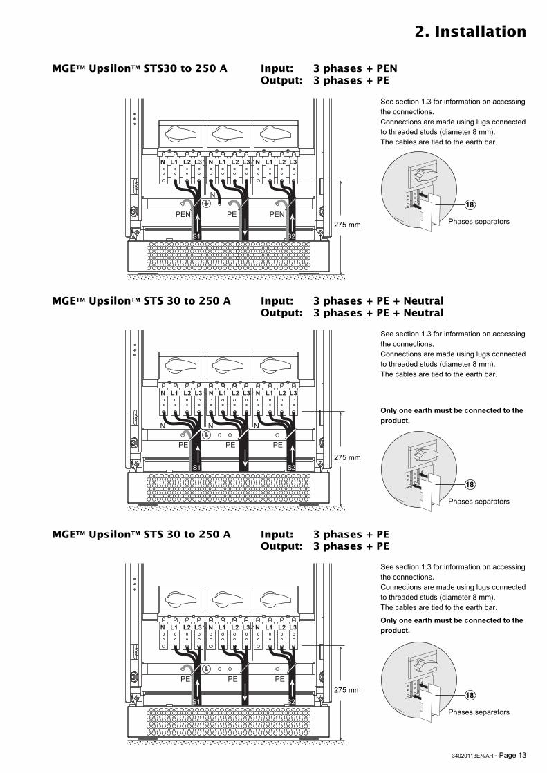
MGETM UpsilonTM STS 30 to 250 A Input: 3 phases + PENOutput: 3 phases + PEN
MGETM UpsilonTM STS 30 to 250 A Input: 3 phases + PENOutput: 3 phases + PE + Neutral
See section 1.3 for information on accessingthe connections.Connections are made using lugs connectedto threaded studs (diameter 8 mm).The cables are tied to the earth bar.
See section 1.3 for information on accessingthe connections.Connections are made using lugs connectedto threaded studs (diameter 8 mm).The cables are tied to the earth bar.
See section 6.1 for information on sizing protection devices and cables (Appendix, Technical data).The Upsilon STS has been designed to allow connection to a TT, TN and IT system (as defined by standards IEC/EN60950-1 or IEC 60364-3).
2.2 Power connections
275 mm
275 mm
18
Phases separators
18
Phases separators
SELV circuits must have a separated path from other circuits or must be protected y a reinforced insulation.
◗ Separate the metallic conduits or ducts containing the power wiring (input / output) by at least 8 cm (3 inches) from themetallic conduits which contain the control wiring.◗ Separate the non-metallic conduits or ducts containing the power wiring (input / output) by at least 30 cm (12 inches)from the conduits which contain the control wiring.◗ Power wiring (input/output) and control wiring must always intersect at right angles.
34020113EN/AH - Page 13
PE PE PE
S1 S2
N L1 L2 L3 N L1 L2 L3 N L1 L2 L3
PE
N
PE PE
N N
S1 S2
N L1 L2 L3 N L1 L2 L3 N L1 L2 L3
PEN
N
PE PEN
S1 S2
N L1 L2 L3 N L1 L2 L3 N L1 L2 L3
2. Installation
See section 1.3 for information on accessingthe connections.Connections are made using lugs connectedto threaded studs (diameter 8 mm).The cables are tied to the earth bar.
See section 1.3 for information on accessingthe connections.Connections are made using lugs connectedto threaded studs (diameter 8 mm).The cables are tied to the earth bar.
MGETM UpsilonTM STS 30 to 250 A Input: 3 phases + PE + NeutralOutput: 3 phases + PE + Neutral
275 mm
275 mm
See section 1.3 for information on accessingthe connections.Connections are made using lugs connectedto threaded studs (diameter 8 mm).The cables are tied to the earth bar.
275 mm
MGETM UpsilonTM STS30 to 250 A Input: 3 phases + PENOutput: 3 phases + PE
Only one earth must be connected to the
product.
Only one earth must be connected to the
product.
18
Phases separators
18
Phases separators
18
Phases separators
MGETM UpsilonTM STS 30 to 250 A Input: 3 phases + PEOutput: 3 phases + PE

Page 14 - 34020113EN/AH
N
PENNPE PEN
S1 S2
N L1 L2 L3 N L1 L2 L3 N L1 L2 L3
N
PEN PEN PENS1 S2
N L1 L2 L3 N L1 L2 L3 N L1 L2 L3
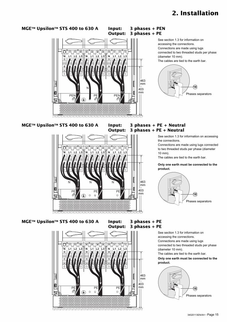
MGETM UpsilonTM STS 400 to 630 A Input: 3 phases + PENOutput: 3 phases + PEN
See section 1.3 for information on accessingthe connections.Connections are made using lugs connectedto two threaded studs per phase (diameter10 mm).The cables are tied to the earth bar.
2. Installation
463mm
403mm
MGETM UpsilonTM STS 400 to 630 A Input: 3 phases + PENOutput: 3 phases + PE + Neutral
See section 1.3 for information on accessingthe connections.Connections are made using lugs connectedto two threaded studs per phase (diameter10 mm).The cables are tied to the earth bar.
463mm
403mm
18
Phases separators
18
Phases separators
See section 6.1 for information on sizing protection devices and cables (Appendix, Technical data).The Upsilon STS has been designed to allow connection to a TT, TN and IT system (as defined by standards IEC/EN60950-1 or IEC 60364-3).
34020113EN/AH - Page 15
PE PE PES1 S2
N L1 L2 L3 N L1 L2 L3 N L1 L2 L3
PE PE PE
N N N
S1 S2
N L1 L2 L3 N L1 L2 L3 N L1 L2 L3
N
PEN PE PENS1 S2
N L1 L2 L3 N L1 L2 L3 N L1 L2 L3
2. Installation
MGETM UpsilonTM STS 400 to 630 A Input: 3 phases + PE + NeutralOutput: 3 phases + PE + Neutral
See section 1.3 for information on accessingthe connections.Connections are made using lugs connectedto two threaded studs per phase (diameter10 mm).The cables are tied to the earth bar.
See section 1.3 for information onaccessing the connections.Connections are made using lugsconnected to two threaded studs per phase(diameter 10 mm).The cables are tied to the earth bar.
463mm
403mm
463mm
403mm
See section 1.3 for information onaccessing the connections.Connections are made using lugsconnected to two threaded studs per phase(diameter 10 mm).The cables are tied to the earth bar.
463mm
403mm
MGETM UpsilonTM STS 400 to 630 A Input: 3 phases + PENOutput: 3 phases + PE
MGETM UpsilonTM STS 400 to 630 A Input: 3 phases + PEOutput: 3 phases + PE
Only one earth must be connected to the
product.
Only one earth must be connected to the
product.
18
Phases separators
18
Phases separators
18
Phases separators

Page 16 - 34020113EN/AH
Cable running for cables entering through the top of the MGETM UpsilonTM STS 30 to250 A cabinet
16
17
Cable-running zone for cables enteringthrough the top
Cable gland plate that must be drilled tocable size
2. Installation

34020113EN/AH - Page 17
JBUS/MODBUS
2. Installation
2.3 Connection of the communication cards
2.4 Connection of the JBUS communication card
RS232:
Pin 2: Rxd (or Txd)Pin 3: Txd (or Rxd)Pin 5: Earth
RS485:
Pin 4: R-Pin 5: T-Pin 8: R+Pin 9: T+
For information on using thecommunication card, see theJBUS communication cardmanual.
Only one communication port
(the RS232 OR the RS485) may
be used at a time.
123456789
Two slots are available in the cardcage 5 for additional cards.
Tie the cables to the cable way 16 on thedoor.
5
Use the cable cut-out 17 toconnect external cables.
16
Do not run the control wires withthe power cables.
17
SELV circuits must have a separated path from other circuits or must be protected y a reinforced insulation.
◗ Separate the metallic conduits or ducts containing the power wiring (input / output) by at least 8 cm (3 inches) from themetallic conduits which contain the control wiring.◗ Separate the non-metallic conduits or ducts containing the power wiring (input / output) by at least 30 cm (12 inches)from the conduits which contain the control wiring.◗ Power wiring (input/output) and control wiring must always intersect at right angles.
Page 18 - 34020113EN/AH
2. Installation
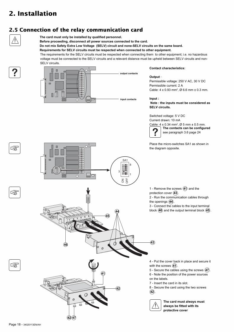
2.5 Connection of the relay communication card
Contact characteristics:
Output :Permissible voltage: 250 V AC, 30 V DCPermissible current: 2 ACable: 4 x 0.93 mm2, Ø 6.6 mm ± 0.3 mm.
Input :
Note : the inputs must be considered as
SELV circuits.
Switched voltage: 5 V DCCurrent drawn: 10 mACable: 4 x 0.34 mm2, Ø 5 mm ± 0.5 mm.
The card must only be installed by qualified personnel.
Before proceeding, disconnect all power sources connected to the card.
Do not mix Safety Extra Low Voltage (SELV) circuit and none-SELV circuits on the same board.
Requirements for SELV circuits must be respected when connected to other equipment.
12 3
45 6
AB
��� ���
input contacts
��� ���
���
���
��
�
�
�
45
46
44
43
4742
41
42
output contacts
The contacts can be configured
see paragraph 3.6 page 24
1 - Remove the screws 41 and theprotection cover 43 .2 - Run the communication cables throughthe openings 44 .3 - Connect the cables to the input terminalblock 46 and the output terminal block 45 .
Place the micro-switches SA1 as shown inthe diagram opposite.
The card must always must
always be fitted with its
protective cover
4 - Put the cover back in place and secure itwith the screws 41 .5 - Secure the cables using the screws 47 .6 - Note the position of the power sourceson the labels.7 - Insert the card in its slot.8 - Secure the card using the two screws42 .
The requirements for the SELV circuits must be respected when connecting them to other equipment; i.e. no hazardousvoltage must be connected to the SELV circuits and a relevant distance must be upheld between SELV circuits and non-SELV circuits.
34020113EN/AH - Page 19
Q1 Q4 Q6 Q2
Q1BP Q2BPQ3
01
01
0 0 011 1
Q1 Q4 Q6 Q2
Q1BP Q2BPQ3
01
01
0 0 011 1
Q1BP
Q1 Q2
Q2BPQ3
S1 S2
3. Operation
3.1 Start-up
3.2 Shutdown
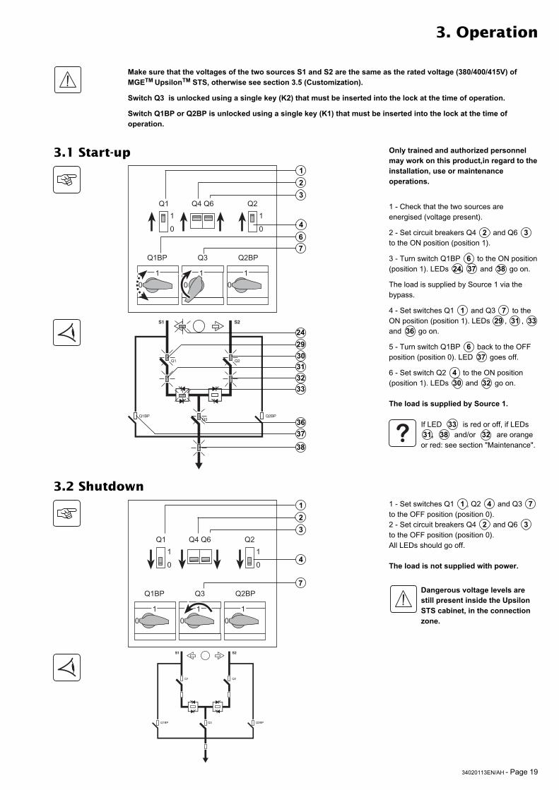
1 - Check that the two sources areenergised (voltage present).
2 - Set circuit breakers Q4 2 and Q6 3to the ON position (position 1).
3 - Turn switch Q1BP 6 to the ON position(position 1). LEDs 24, 37 and 38 go on.
The load is supplied by Source 1 via thebypass.
4 - Set switches Q1 1 and Q3 7 to theON position (position 1). LEDs 29 , 31 , 33
and 36 go on.
5 - Turn switch Q1BP 6 back to the OFFposition (position 0). LED 37 goes off.
6 - Set switch Q2 4 to the ON position(position 1). LEDs 30 and 32 go on.
The load is supplied by Source 1.
If LED 33 is red or off, if LEDs31, 38 and/or 32 are orangeor red: see section "Maintenance".
1 - Set switches Q1 1 , Q2 4 and Q3 7to the OFF position (position 0).2 - Set circuit breakers Q4 2 and Q6 3to the OFF position (position 0).All LEDs should go off.
The load is not supplied with power.
Dangerous voltage levels are
still present inside the Upsilon
STS cabinet, in the connection
zone.
1
2
3
4
6
7
1
2
3
4
7
29
30
31
32
33
36
37
38
Make sure that the voltages of the two sources S1 and S2 are the same as the rated voltage (380/400/415V) of
MGETM
UpsilonTM
STS, otherwise see section 3.5 (Customization).
Switch Q3 is unlocked using a single key (K2) that must be inserted into the lock at the time of operation.
Switch Q1BP or Q2BP is unlocked using a single key (K1) that must be inserted into the lock at the time of
operation.
Q1BP
Q1 Q2
Q2BPQ3
S1 S2
24
Only trained and authorized personnel
may work on this product,in regard to the
installation, use or maintenance
operations.
Page 20 - 34020113EN/AH
Q1BP
Q1 Q2
Q2BPQ3
S1 S2
Q1BP
Q1 Q2
Q2BPQ3
S1 S2
Q1BP
Q1 Q2
Q2BPQ3
S1 S2
3. Operation
3.3 Normal mode. Operation on preferred source S1Operation on the preferred source
Automatic transfer to the alternate source
Manual transfer to the alternate source
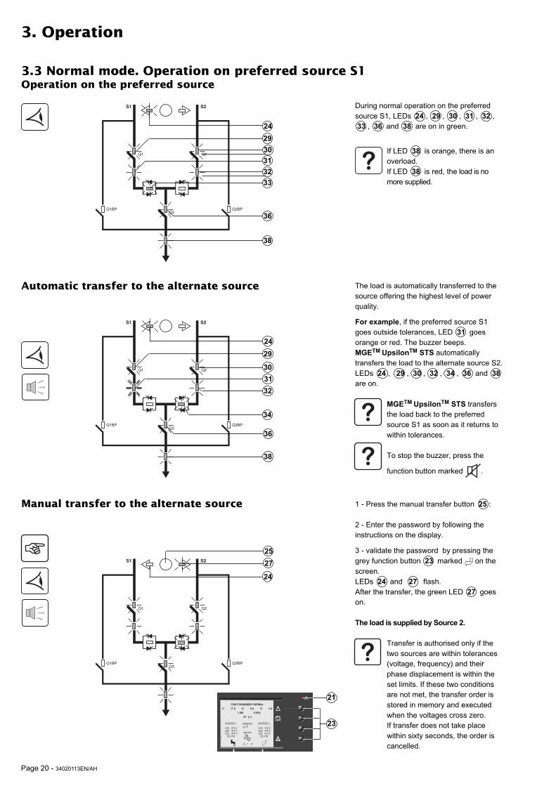
During normal operation on the preferredsource S1, LEDs 24 , 29 , 30 , 31 , 32 ,33 , 36 and 38 are on in green.
The load is automatically transferred to thesource offering the highest level of powerquality.
For example, if the preferred source S1goes outside tolerances, LED 31 goesorange or red. The buzzer beeps.MGETM UpsilonTM STS automaticallytransfers the load to the alternate source S2.LEDs 24 , 29 , 30 , 32 , 34 , 36 and 38
are on.
MGETM
UpsilonTM
STS transfersthe load back to the preferredsource S1 as soon as it returns towithin tolerances.
To stop the buzzer, press the
function button marked .
25
27
1 - Press the manual transfer button 25 :
2 - Enter the password by following theinstructions on the display.
3 - validate the password by pressing thegrey function button 23 marked on thescreen.LEDs 24 and 27 flash.After the transfer, the green LED 27 goeson.
The load is supplied by Source 2.
Transfer is authorised only if thetwo sources are within tolerances(voltage, frequency) and theirphase displacement is within theset limits. If these two conditionsare not met, the transfer order isstored in memory and executedwhen the voltages cross zero.If transfer does not take placewithin sixty seconds, the order iscancelled.
29
30
31
32
33
36
38
24
29
30
31
32
36
38
24
34
If LED 38 is orange, there is anoverload.If LED 38 is red, the load is nomore supplied.
24
Menu
Alarme
Mesures
Etats
Historique
Transfert
Alarme
Mesures
Etats
Historique
Menu
UPS galaxy
deuxième étage, salle 13
UPS galaxy
deuxième étage, salle 14
Source secours
UPS galaxy
deuxième étage, salle 13
Source prioritaire
UPS galaxy
deuxième étage, salle 14
FONCTIONNEMENT NORMAL
I1 17 A I2 9 A I3 2 A
1 KW 6 KVA
FP 0.3
preferred
synchro
SOURCE 1
= 0°
U12 413 VU23 414 VU31 414 V 50.0 Hz
SOURCE 2U12 412 VU23 415 VU31 413 V 50.0 Hz
volt
23
21

34020113EN/AH - Page 21
Manual transfer to an out-of-phase alternate source
3. Operation
When the two sources are not in phase, it ispossible to force manual transfer using thecommands on the screen, after entering apassword.1 - Enter the password (see section 3.5,Customization).2 - Follow the instructions provided on thescreen.
Q1BP
Q1 Q2
Q2BPQ3
S1 S2

Page 22 - 34020113EN/AH
3. Operation
3.4 Display screens
�������� ����
��� ���������
��������� �� � ��
�����������
��������
���
� � ��
��������� �
�� ��
���� ������
���������
��������������
�� ����������������� �
�� �������������� �
�����
���������
� �������
������������������
� ���!������������
��"����#�����������
���� ������
�� ��
� ��� ��
$ ��%��&�
$��'� (������ ��
)�**�������&�
������� &�
�� ����' �����+
,����� ��* ����
$�(����� ���
��������
����
� � � �� � � �� � � �
����������������
�������������������������������������� �������������!�������������
��"#����������������$�"��
�%����&!
'�������+
�(�����
�,�-
.�/01
�-���200���2���234���3���232�����5464�7*
�,�2
�-���232���2���228���3���234�����5464�7*
����9����
)(' ���'����+���
���� ����������������� �
� ���'�'����+���
34020113EN/AH - Page 23
3. Operation
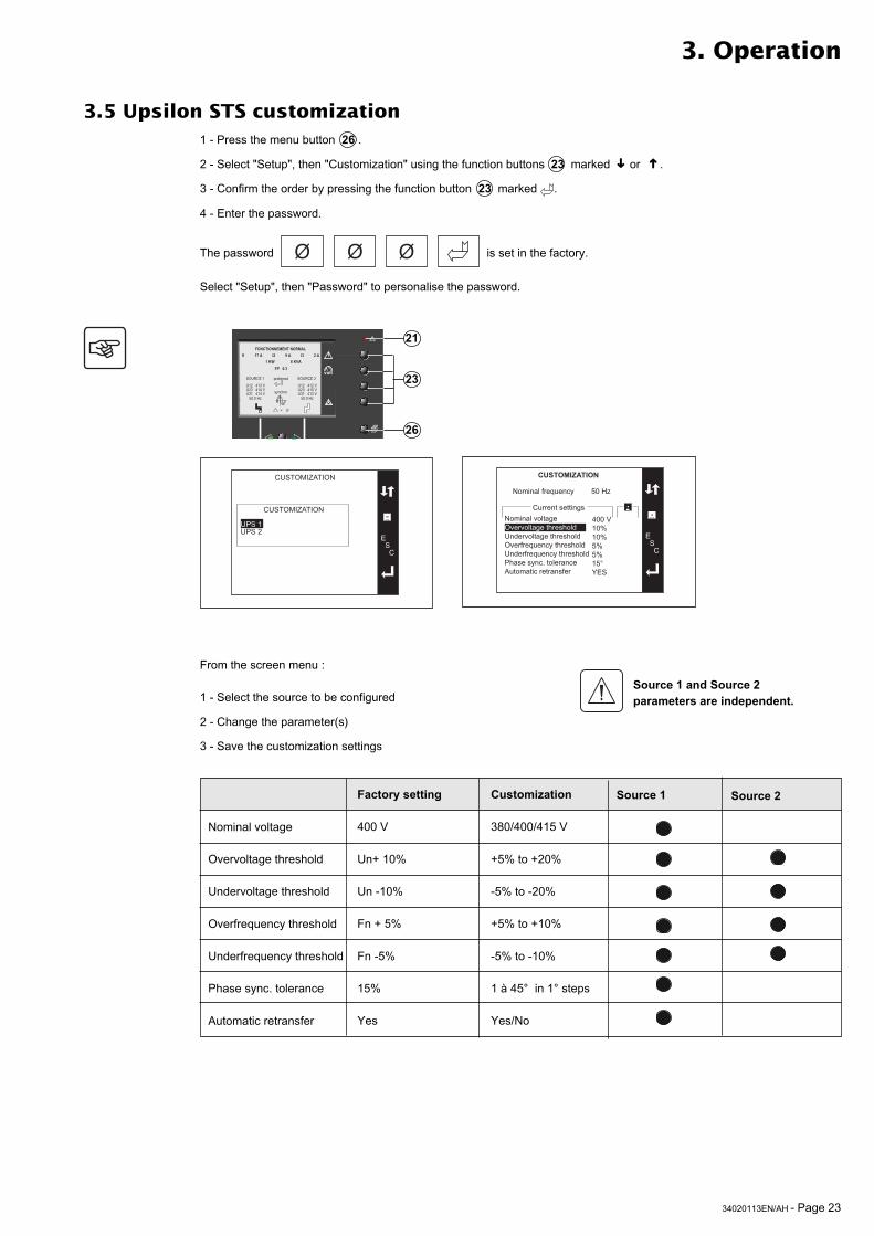
3.5 Upsilon STS customization1 - Press the menu button 26 .
2 - Select "Setup", then "Customization" using the function buttons 23 marked or .
3 - Confirm the order by pressing the function button 23 marked .
4 - Enter the password.
The password Ø Ø Ø is set in the factory.
Select "Setup", then "Password" to personalise the password.
➜
➜
Menu
Alarme
Mesures
Etats
Historique
Transfert
Alarme
Mesures
Etats
Historique
Menu
UPS galaxy
deuxième étage, salle 13
UPS galaxy
deuxième étage, salle 14
Source secours
UPS galaxy
deuxième étage, salle 13
Source prioritaire
UPS galaxy
deuxième étage, salle 14
FONCTIONNEMENT NORMAL
I1 17 A I2 9 A I3 2 A
1 KW 6 KVA
FP 0.3
preferred
synchro
SOURCE 1
= 0°
U12 413 VU23 414 VU31 414 V 50.0 Hz
SOURCE 2U12 412 VU23 415 VU31 413 V 50.0 Hz
volt
23
21
26
��� �:;��: �
��������
��� �:;��: �
�,�-�,�2
��&�� ������ �� ������� �����������+��+������ �����������+ ������<����(���������+��+�����<����(���������+,� ����(��6������ �������& �������� �����
'������(�����
��������
����������������
044��-4=-4=5=5=-51#�
��&�� �����<����( 54�7*
Nominal voltage
Overvoltage threshold
Undervoltage threshold
Overfrequency threshold
Underfrequency threshold
Phase sync. tolerance
Automatic retransfer
Factory setting
400 V
Un+ 10%
Un -10%
Fn + 5%
Fn -5%
15%
Yes
Customization
380/400/415 V
+5% to +20%
-5% to -20%
+5% to +10%
-5% to -10%
1 à 45° in 1° steps
Yes/No
Source 1 Source 2
From the screen menu :
1 - Select the source to be configured
2 - Change the parameter(s)
3 - Save the customization settings
Source 1 and Source 2
parameters are independent.

Page 24 - 34020113EN/AH
6
5
4
3
2
1
B A
3.6 Customization of the relay communication card
3. Operation
Source 2 (S2) out of tolerance
Source 1 (S1) out of tolerance
Overload status condition
STS fault
General alarm(fault on one of the sources or on the STS
Load-supplied status condition (presence or absence of power to the load)
Factory settings
Not used
The output contacts are controlleddirectly by the STS.All changes of state of input contacts aretransmitted to the STS.
Input and output customization
Status conditions
available on each output contact
- No associated function - Equipment powered - Overload - General alarm - Device alarm - S1 (source 1) out of tolerance - S2 (source 2) out of tolerance - Phase hors tolérances - S1 active - S2 active - S1 priority - Transfer forbidden - Re-transfer authorized
Commands
available on each input contact
- No associated function - Fault acknowledgement - Selection S1 (source 1) - Selection S2 (source 2) - Automatic re-transfer forbidden - Automatic re-transfer authorized - Transfer forbidden - Transfer authorized
Outputs (contacts 1 to 6)
Contact configuration
��� ���
��
���
��
�
�
N.O.N.C.
The contacts can be individually configured forNormally Closed (N.C.) operation by placingmicro-switches SA2 to ON.
All contacts* are Normally Open (N.O.) :
* External contacts for the inputs .
8 B7 A6 65 54 43 32 21 1
If the micro-switch is OFF, the signal is N.O.,otherwise it is N.C.
Open Inactive Commandstate inactive
closed Active Commandstate active
Inputs (contacts A and B)
Micro - Contact switch
Contact Output Input

34020113EN/AH - Page 25
4. Maintenance
4.1 Identification of anomalies
Relay communication card indicator anomalies
If the communication card green indicator remains continuously off:
◗ Check the card is correctly inserted into its slot and its protective cover is correctly screwed-on.◗ Check the STS is powered.◗ Remove the card and re-insert it.
If the communication card green indicator remains continuously on:
◗ Remove the card and re-insert it.
If an alarm is incorrectly triggered:
◗ Check the signal’s NO/NC configuration corresponds to your installation (micro-switches SA2, §3.6).◗ Check the STS operating mode is correctly configured (micro-switches SA1, §2.5).
If the problem continues, contact our after-sales service (details available at www.apc.com).
General-alarm
LED 21
-
-
S1 31 or S2 32
LED
-
-
-
-
-
Static-switch
LED 33 or 34
-
-
-
-
-
-
The meaning of all these anomalies are detailed on the display:Select the alarm: the corresponding informations are displayed.
Buzzer
Beeps
Beeps
Beeps
Beeps
Beeps
Beeps
Beeps
Meaning
Internal STS fault.
Degraded source, loadstill supplied.
Source outsidetolerances, no voltage.The load cannot besupplied by this source.
Static-switch fault.
Overload. (1)
Load not supplied.
Source state notmeasurable.
System output
LED 38
-
-
-
-
red
red
red
red
red
orange
orange
red
red
STS indicator anomalies
(1) The product is overloaded without any other consequence for the load.
red
flashingorange
Only trained and authorized personnel may work on this product, in regard to the installation, use or maintenance
operations.

Page 26 - 34020113EN/AH
4.2 Transfer to the manual bypass
Before any servicing, Upsilon STS must be de-energised by transferring to the bypass.
4. Maintenance
In order to continue supplying the load , switch Q1BP or Q2BP must be closed (depending on theactive source) before opening switch Q3.
Switch Q3 is unlocked using a single key (K2) that must be inserted into the lock at the time
of operation.
Switch Q1BP or Q2BP is unlocked using a single key (K1) that must be inserted into the lock
at the time of operation.
The procedure for switching the manual by-pass is detailed in two places :
Press the menu key 26
Go to the "Maintenance" menu and then to the "Bypass procedure" page using the function keys 23
Follow the instructions on the display
HMI
In the device
Menu
Alarme
Mesures
Etats
Historique
Transfert
Alarme
Mesures
Etats
Historique
Menu
UPS galaxy
deuxième étage, salle 13
UPS galaxy
deuxième étage, salle 14
Source secours
UPS galaxy
deuxième étage, salle 13
Source prioritaire
UPS galaxy
deuxième étage, salle 14
FONCTIONNEMENT NORMAL
I1 17 A I2 9 A I3 2 A
1 KW 6 KVA
FP 0.3
preferred
synchro
SOURCE 1
= 0°
U12 413 VU23 414 VU31 414 V 50.0 Hz
SOURCE 2U12 412 VU23 415 VU31 413 V 50.0 Hz
volt
23
21
26
The procedure for switching to manual by-pass is printed on the device.

34020113EN/AH - Page 27
5. Environment
This product has been designed to respect the environment
It does not contain CFCs or HCFCs.It is manufactured on a production site certified ISO 14001.
UPS recycling at the end of service life
APC by Schneider Electric undertakes to recycle, by certified companies and in compliance with all applicable regulations,all products recovered at the end of their service life (contact your APC by Schneider Electric branch office).
Packing
Packing materials must be recycled in compliance with all applicable regulations.
Web site: www.apc.com
Page 28 - 34020113EN/AH
6. Appendix
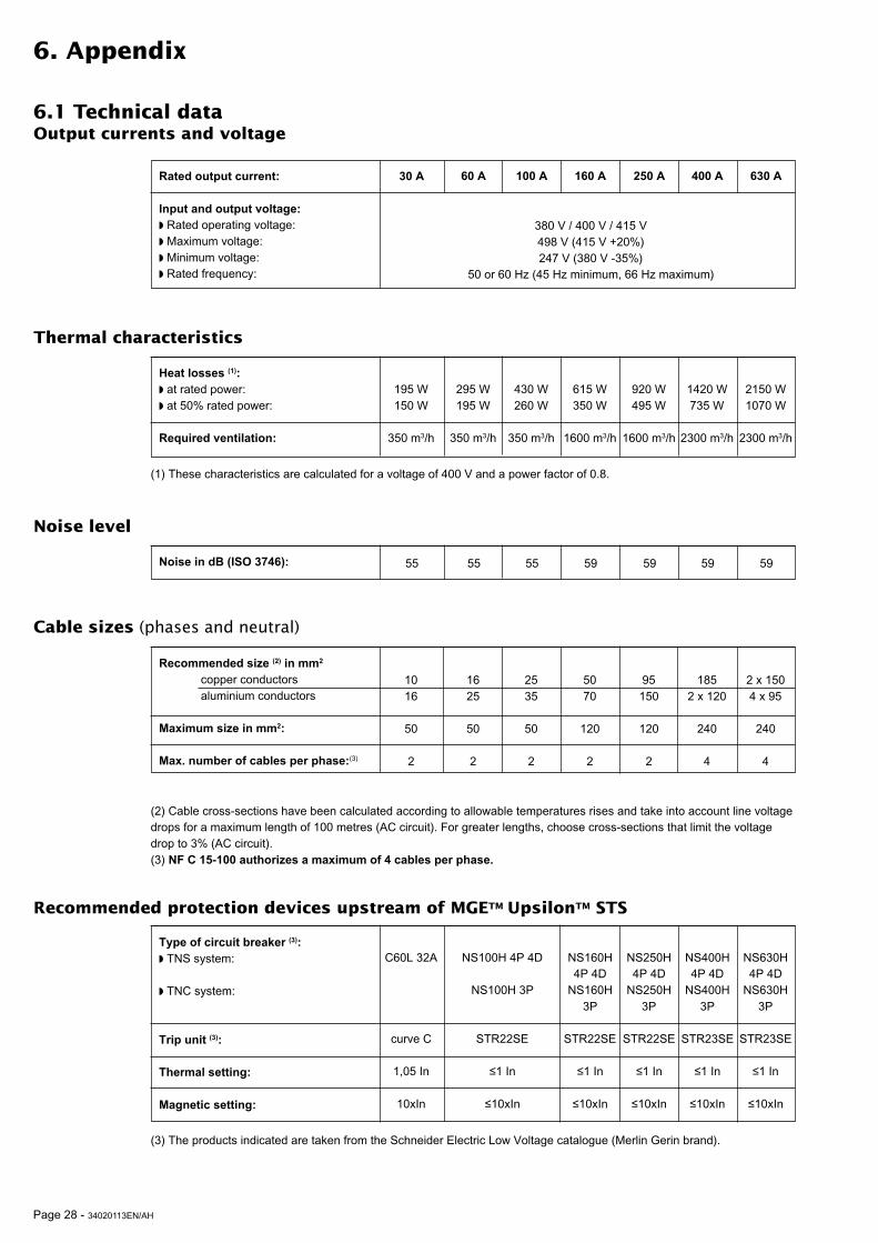
6.1 Technical dataOutput currents and voltage
Rated output current:
Input and output voltage:
◗ Rated operating voltage:◗ Maximum voltage:◗ Minimum voltage:◗ Rated frequency:
30 A
380 V / 400 V / 415 V498 V (415 V +20%)247 V (380 V -35%)
50 or 60 Hz (45 Hz minimum, 66 Hz maximum)
60 A 100 A 160 A 250 A 400 A 630 A
Thermal characteristics
(1) These characteristics are calculated for a voltage of 400 V and a power factor of 0.8.
Heat losses (1):
◗ at rated power:◗ at 50% rated power:
Required ventilation:
195 W150 W
350 m3/h
295 W195 W
350 m3/h
430 W260 W
350 m3/h
615 W350 W
1600 m3/h
920 W495 W
1600 m3/h
1420 W735 W
2300 m3/h
2150 W1070 W
2300 m3/h
Noise level
Recommended protection devices upstream of MGETM UpsilonTM STS
Cable sizes (phases and neutral)
Noise in dB (ISO 3746):
Type of circuit breaker (3):
◗ TNS system:
◗ TNC system:
Trip unit (3):
Thermal setting:
Magnetic setting:
C60L 32A
curve C
1,05 In
10xIn
NS100H 4P 4D
NS100H 3P
STR22SE
≤1 In
≤10xIn
NS160H4P 4D
NS160H3P
STR22SE
≤1 In
≤10xIn
NS400H4P 4D
NS400H3P
STR23SE
≤1 In
≤10xIn
NS250H4P 4D
NS250H3P
STR22SE
≤1 In
≤10xIn
NS630H4P 4D
NS630H3P
STR23SE
≤1 In
≤10xIn
55 55 55 59 59 59 59
(3) The products indicated are taken from the Schneider Electric Low Voltage catalogue (Merlin Gerin brand).
Recommended size (2) in mm2
copper conductorsaluminium conductors
Maximum size in mm2:
Max. number of cables per phase:(3)
1016
50
2
1625
50
2
2535
50
2
5070
120
2
95150
120
2
1852 x 120
240
4
2 x 1504 x 95
240
4
(2) Cable cross-sections have been calculated according to allowable temperatures rises and take into account line voltagedrops for a maximum length of 100 metres (AC circuit). For greater lengths, choose cross-sections that limit the voltagedrop to 3% (AC circuit).(3) NF C 15-100 authorizes a maximum of 4 cables per phase.
34020113EN/AH - Page 29
"-
�)��������*�������
"2
"3 "2),"-),
�� ��
6. Appendix
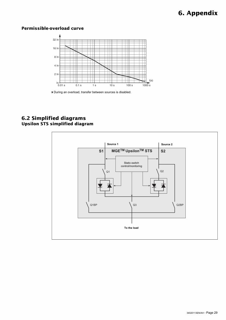
6.2 Simplified diagramsUpsilon STS simplified diagram
Static-switchcontrol/monitoring
Source 2Source 1
To the load
Permissible-overload curve
◗ During an overload, transfer between sources is disabled.
In
2 In
4 In
8 In
32 In
16 In
t(s)
0.01 s 0.1 s 1 s 10 s 100 s 1000 s
Page 30 - 34020113EN/AH
6. Appendix
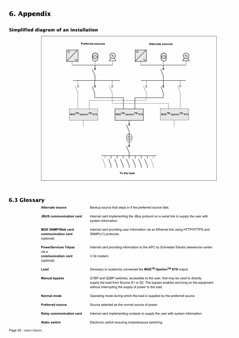
6.3 GlossaryAlternate source Backup source that steps in if the preferred source fails.
JBUS communication card Internal card implementing the JBus protocol on a serial link to supply the user withsystem information.
MGE SNMP/Web card Internal card providing user information via an Ethernet link using HTTP/HTTPS andcommunication card SNMP(v1) protocols.(optional)
PowerServices Telpac Internal card providing information to the APC by Schneider Electric teleservice centrevia acommunication card V.34 modem.(optional)
Load Device(s) or system(s) connected the MGETM UpsilonTM STS output.
Manual bypass Q1BP and Q2BP switches, accessible to the user, that may be used to directlysupply the load from Source S1 or S2. The bypass enables servicing on the equipmentwithout interrupting the supply of power to the load.
Normal mode Operating mode during which the load is supplied by the preferred source.
Preferred source Source selected as the normal source of power.
Relay communication card Internal card implementing contacts to supply the user with system information.
Static switch Electronic switch ensuring instantaneous switching.
Simplified diagram of an installation
Alternate sourcesPreferred sources
To the load
�)��������*��������)��������*������� �)��������*�������
34020113EN/AH - Page 31
6. Appendix
6.4 IndexA
Alarms ............................................................................ 25Anomalies ...................................................................... 25
B
Buzzer ............................................................................ 25
C
Cable sizes .................................................................... 28Communication cards
JBUS ...................................................................... 10MGE SNMP/Web card ........................................... 10PowerServices Telpac ................................................Relay ...................................................................... 10
ConnectionsAccess ...................................................................... 8JBUS communication card ..................................... 17Power cables .................................. 12, 13, 14, 15, 16Relay communication card ..................................... 18Through the top ...................................................... 16
Customization .......................................................... 23, 24
D
Dimensions ...................................................................... 7Display ........................................................................... 22
F
Faults ............................................................................. 25Frequency ...................................................................... 28
L
Layout of components ...................................................... 8LEDs .......................................................................... 9, 25Links
RS232 .................................................................... 10RS485 .................................................................... 10
Losses ............................................................................ 28
M
Man / machine interface ................................................... 9Manual bypass ............................................................... 26
O
Operating modes ..................................................... 20, 21Overloads ....................................................................... 28
R
Recommended protection .............................................. 28Recycling ....................................................................... 27
S
Safety rules ...................................................................... 3Shutdown ....................................................................... 19Start-up .......................................................................... 19
V
Ventilation ...................................................................... 28Voltages ......................................................................... 28
W
Weight .............................................................................. 7