Gait Sequence Analysis using Frieze Patterns Sequence Analysis using Frieze Patterns Yanxi Liu,...
21
Gait Sequence Analysis using Frieze Patterns Yanxi Liu, Robert T. Collins and Yanghai Tsin CMU-RI-TR-01-38 The Robotics Institute Carnegie Mellon University Pittsburgh, PA 15213 c 2001 Carnegie Mellon University This research is supported in part by an ONR research grant N00014-00-1-0915 (HumanID), and in part by an NSF research grant IIS-0099597.
Transcript of Gait Sequence Analysis using Frieze Patterns Sequence Analysis using Frieze Patterns Yanxi Liu,...
Gait Sequence Analysis using
Frieze PatternsYanxi Liu, Robert T. Collins and Yanghai Tsin
CMU-RI-TR-01-38
The Robotics Institute
Carnegie Mellon University
Pittsburgh, PA 15213
c 2001 Carnegie Mellon University
This research is supported in part by an ONR research grant N00014-00-1-0915 (HumanID), and in part by an
NSF research grant IIS-0099597.
ABSTRACT
We analyze walking people using a gait sequence representation that bypasses the need for
frame-to-frame tracking of body parts. The gait representation maps a video sequence of silhou-
ettes into a pair of two-dimensional spatio-temporal patterns that are periodic along the time axis.
Mathematically, such patterns are called “frieze” patterns and associated symmetry groups “frieze
groups”. With the help of a walking humanoid avatar, we explore variation in gait frieze patterns
with respect to viewing angle, and find that the frieze groups of the gait patterns and their canon-
ical tiles enable us to estimate viewing direction. In addition, analysis of periodic patterns allows
us to determine the dynamic time warping and affine scaling that aligns two gait sequences from
similar viewpoints. We show how gait alignment can be used to perform human identification and
model-based body part segmentation.
1
1 Motivation
Automated visual measurement of human body size and pose is difficult due to non-rigid articu-
lation and occlusion of body parts from many viewpoints. The problem is simplified during gait
analysis, since we observe people performing the same activity. Although individual gaits vary
due to factors such as physical build, body weight, shoe heel height, clothing and the emotional
state of the walker, at a coarse level the basic pattern of bipedal motion is the same across healthy
adults, and each person’s body passes through the same sequence of canonical poses while walk-
ing. We have experimented with a simple, viewpoint-specific spatio-temporal representation of
gait. The representation collapses a temporal sequence of body silhouette images into a periodic
two-dimensional pattern. This paper explores the use of these frieze patterns for viewing angle
determination, human identification, and non-rigid gait sequence alignment.
2 Related Work
Many approaches to analyzing gait sequences are based on tracking the body as a kinematic link-
age. Model-based kinematic tracking of a walking person was pioneered by Hogg [7], and other
influential approaches in this area are [2, 3]. These approaches are often brittle, since the human
body has many degrees of freedom that cannot be observed well in a 2D image sequence. Our
work is more closely related to approaches based on pattern analysis of spatio-temporal represen-
tations. Niyogi and Adelson delineate a person’s limbs by fitting deformable contours to patterns
that emerge from taking spatio-temporal slices of the XYT volume formed from an image se-
quence [14]. Little and Boyd analyze temporal signals computed from optic flow to determine
human identity from gait [10]. The key point is that analyzing features over a whole temporal
sequence is a powerful method for overcoming noise in individual frames.
Liu and Picard [11] proposed to detect periodic motions by studying treating temporal changes
of individual pixels as 1D signals whose frequencies can be extracted. Seitz and Dyer [15] replace
the concept of period by the instantaneous period, the duration from the current time instant at
which the same pattern reappears. Their representation is effective in studying varying speed cyclic
motions and detecting irregularities. Cutler and Davis [4] also measure self-similarity over time
to form an evolving 2D pattern. Time-frequency analysis of this pattern summarizes interesting
properties of the motion, such as object class and number of objects.
2

3 A Spatio-Temporal Gait Representation
Consider a sequence of binary silhouette imagesb(t) � b(x; y; t), indexed spatially by pixel loca-
tion (x; y) and temporally by timet. Form a new 2D imageFC(x; t) =P
y b(x; y; t), where each
column (indexed by timet) is the vertical projection (column sum) of silhouette imageb(t), as
shown in Figure 1. Each valueFC(x; t) is then a count of the number of silhouette pixels that are
“on” in columnx of silhouette imageb(t). The result is a 2D pattern, formed by stacking column
projections together to form a spatio-temporal pattern. A second patternFR(y; t) =P
x b(x; y; t)
can be constructed by stacking row projections. Since a human gait is periodic with respect to
time,FC andFR are also periodic along the time dimension. A two-dimensional pattern that re-
peats along one dimension is called afriezepattern in the mathematics and geometry literature, a
tile of a frieze pattern is the smallest rectangle region whose translated copies can cover the whole
pattern without overlapping or gaps. Group theory provides a powerful tool for analyzing such
patterns (Section 4.1).
Figure 1: Spatio-temporal gait representations are generated by projecting the body silhouette
along its columns and rows, then stacking these 1D projections over time to form 2D patterns that
are periodic along the time dimension. A 2D pattern that repeats along one dimension is called a
“frieze” pattern.
Figure 2 shows the column projection frieze patternFC extracted from a roughly 30 second
long sequence of a person walking along a test course. Note the changes in appearance of the
frieze pattern as the walking direction changes. In our experiments, body silhouette extraction
3
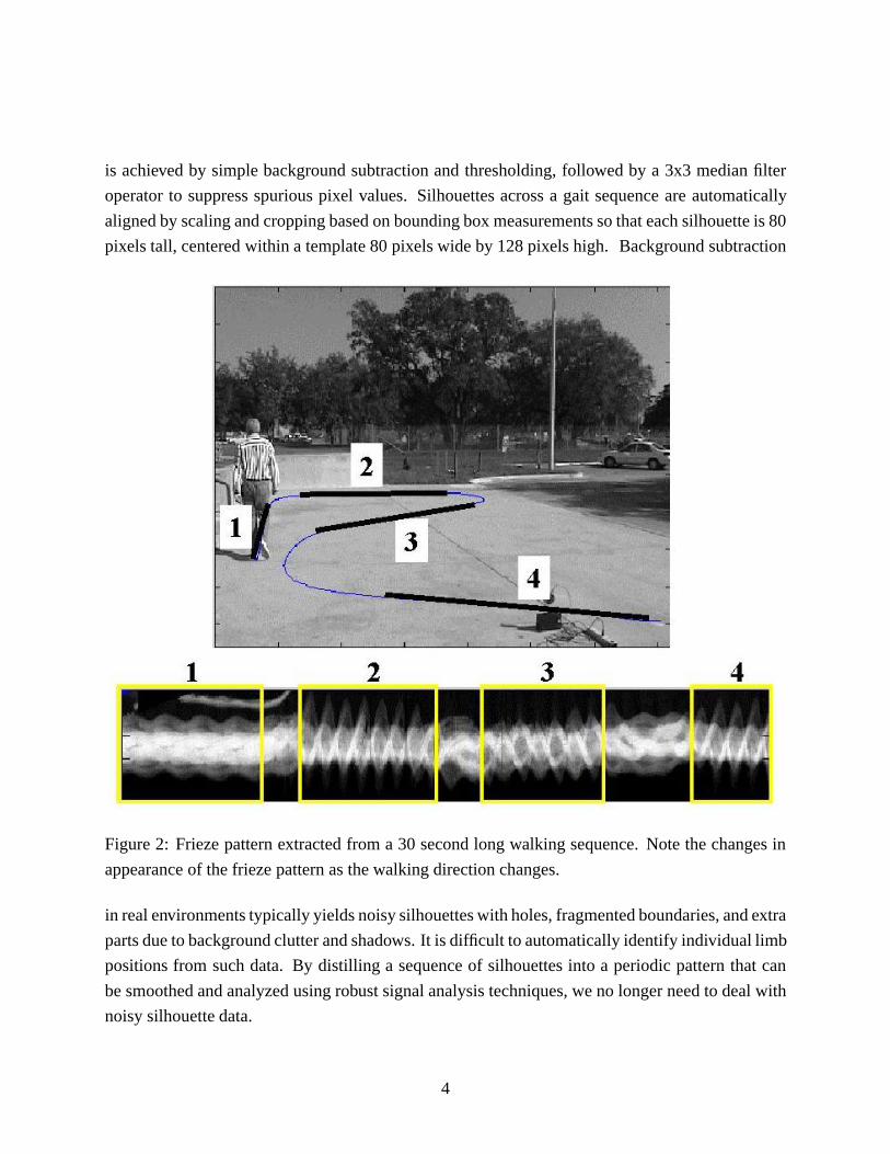
is achieved by simple background subtraction and thresholding, followed by a 3x3 median filter
operator to suppress spurious pixel values. Silhouettes across a gait sequence are automatically
aligned by scaling and cropping based on bounding box measurements so that each silhouette is 80
pixels tall, centered within a template 80 pixels wide by 128 pixels high. Background subtraction
Figure 2: Frieze pattern extracted from a 30 second long walking sequence. Note the changes in
appearance of the frieze pattern as the walking direction changes.
in real environments typically yields noisy silhouettes with holes, fragmented boundaries, and extra
parts due to background clutter and shadows. It is difficult to automatically identify individual limb
positions from such data. By distilling a sequence of silhouettes into a periodic pattern that can
be smoothed and analyzed using robust signal analysis techniques, we no longer need to deal with
noisy silhouette data.
4
4 Model-Based Gait Analysis
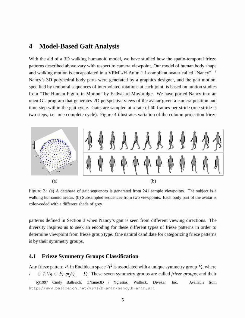
With the aid of a 3D walking humanoid model, we have studied how the spatio-temporal frieze
patterns described above vary with respect to camera viewpoint. Our model of human body shape
and walking motion is encapsulated in a VRML/H-Anim 1.1 compliant avatar called “Nancy”.1
Nancy’s 3D polyhedral body parts were generated by a graphics designer, and the gait motion,
specified by temporal sequences of interpolated rotations at each joint, is based on motion studies
from “The Human Figure in Motion” by Eadweard Muybridge. We have ported Nancy into an
open-GL program that generates 2D perspective views of the avatar given a camera position and
time step within the gait cycle. Gaits are sampled at a rate of 60 frames per stride (one stride is
two steps, i.e. one complete cycle). Figure 4 illustrates variation of the column projection frieze
(a) (b)
Figure 3: (a) A database of gait sequences is generated from 241 sample viewpoints. The subject is a
walking humanoid avatar. (b) Subsampled sequences from two viewpoints. Each body part of the avatar is
color-coded with a different shade of grey.
patterns defined in Section 3 when Nancy’s gait is seen from different viewing directions. The
diversity inspires us to seek an encoding for these different types of frieze patterns in order to
determine viewpoint from frieze group type. One natural candidate for categorizing frieze patterns
is by their symmetry groups.
4.1 Frieze Symmetry Groups Classification
Any frieze patternPi in Euclidean spaceR2 is associated with a unique symmetry groupFi, where
i = 1::7; 8g 2 Fi; g(Pi) = Pi. These seven symmetry groups are calledfrieze groups, and their
1 c 1997 Cindy Ballreich, 3Name3D / Yglesias, Wallock, Divekar, Inc. Available from
http://www.ballreich.net/vrml/h-anim/nancy h-anim.wrl
5
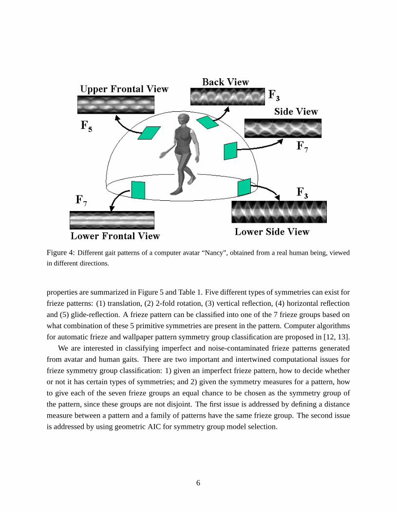
Figure 4:Different gait patterns of a computer avatar “Nancy”, obtained from a real human being, viewed
in different directions.
properties are summarized in Figure 5 and Table 1. Five different types of symmetries can exist for
frieze patterns: (1) translation, (2) 2-fold rotation, (3) vertical reflection, (4) horizontal reflection
and (5) glide-reflection. A frieze pattern can be classified into one of the 7 frieze groups based on
what combination of these 5 primitive symmetries are present in the pattern. Computer algorithms
for automatic frieze and wallpaper pattern symmetry group classification are proposed in [12, 13].
We are interested in classifying imperfect and noise-contaminated frieze patterns generated
from avatar and human gaits. There are two important and intertwined computational issues for
frieze symmetry group classification: 1) given an imperfect frieze pattern, how to decide whether
or not it has certain types of symmetries; and 2) given the symmetry measures for a pattern, how
to give each of the seven frieze groups an equal chance to be chosen as the symmetry group of
the pattern, since these groups are not disjoint. The first issue is addressed by defining a distance
measure between a pattern and a family of patterns have the same frieze group. The second issue
is addressed by using geometric AIC for symmetry group model selection.
6
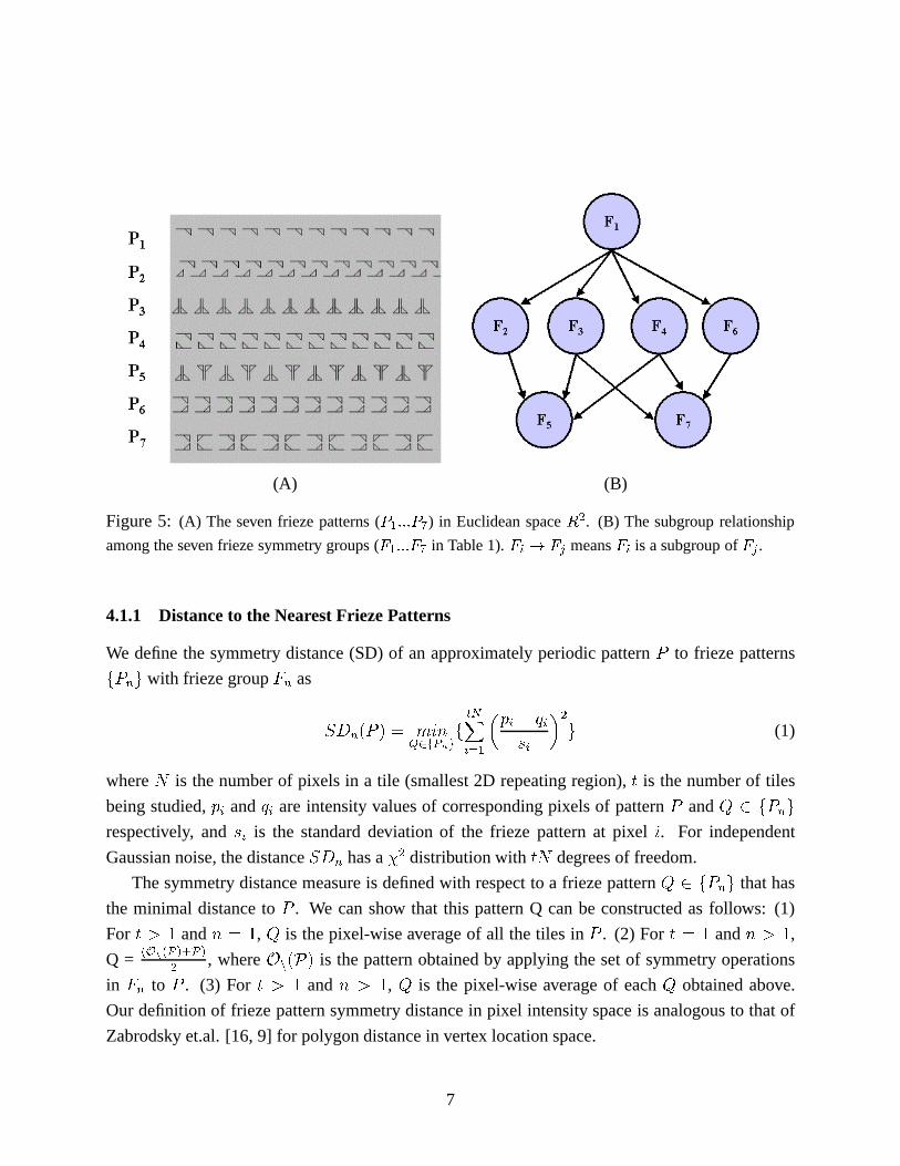
(A) (B)
Figure 5: (A) The seven frieze patterns (P1:::P7) in Euclidean spaceR2. (B) The subgroup relationship
among the seven frieze symmetry groups (F1:::F7 in Table 1).Fi ! Fj meansFi is a subgroup ofFj .
4.1.1 Distance to the Nearest Frieze Patterns
We define the symmetry distance (SD) of an approximately periodic patternP to frieze patterns
fPng with frieze groupFn as
SDn(P ) = minQ2fPng
f
tNXi=1
�pi � qi
si
�2g (1)
whereN is the number of pixels in a tile (smallest 2D repeating region),t is the number of tiles
being studied,pi andqi are intensity values of corresponding pixels of patternP andQ 2 fPng
respectively, andsi is the standard deviation of the frieze pattern at pixeli. For independent
Gaussian noise, the distanceSDn has a�2 distribution withtN degrees of freedom.
The symmetry distance measure is defined with respect to a frieze patternQ 2 fPng that has
the minimal distance toP . We can show that this pattern Q can be constructed as follows: (1)
For t > 1 andn = 1, Q is the pixel-wise average of all the tiles inP . (2) Fort = 1 andn > 1,
Q =(On(P)+P)
2, whereOn(P) is the pattern obtained by applying the set of symmetry operations
in Fn to P . (3) For t > 1 andn > 1, Q is the pixel-wise average of eachQ obtained above.
Our definition of frieze pattern symmetry distance in pixel intensity space is analogous to that of
Zabrodsky et.al. [16, 9] for polygon distance in vertex location space.
7
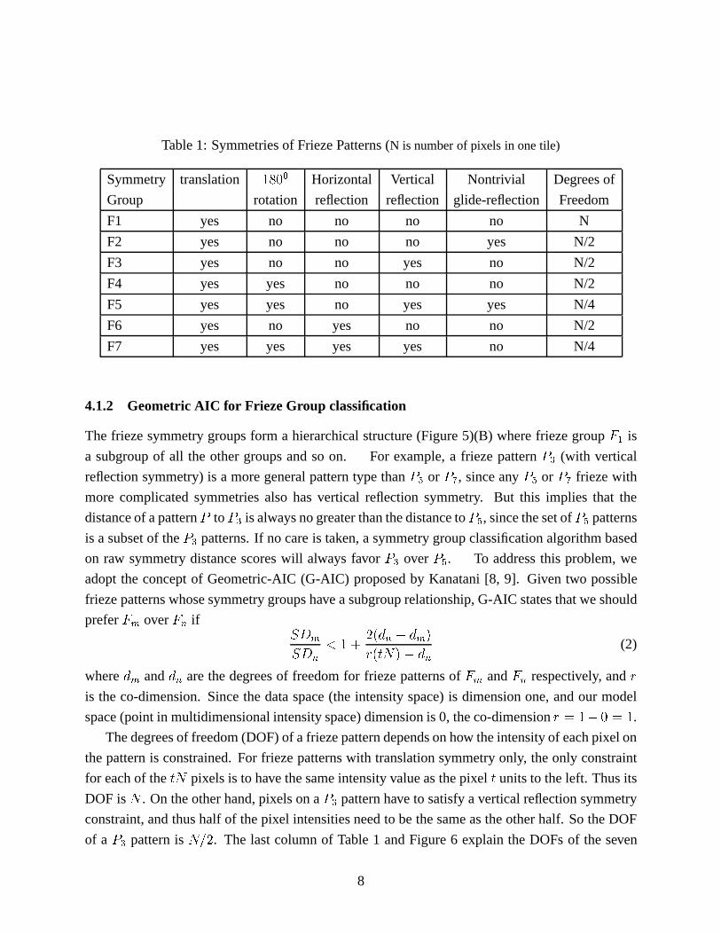
Table 1: Symmetries of Frieze Patterns (N is number of pixels in one tile)
Symmetry translation 1800 Horizontal Vertical Nontrivial Degrees of
Group rotation reflection reflection glide-reflection Freedom
F1 yes no no no no N
F2 yes no no no yes N/2
F3 yes no no yes no N/2
F4 yes yes no no no N/2
F5 yes yes no yes yes N/4
F6 yes no yes no no N/2
F7 yes yes yes yes no N/4
4.1.2 Geometric AIC for Frieze Group classification
The frieze symmetry groups form a hierarchical structure (Figure 5)(B) where frieze groupF1 is
a subgroup of all the other groups and so on. For example, a frieze patternP3 (with vertical
reflection symmetry) is a more general pattern type thanP5 or P7, since anyP5 or P7 frieze with
more complicated symmetries also has vertical reflection symmetry. But this implies that the
distance of a patternP toP3 is always no greater than the distance toP5, since the set ofP5 patterns
is a subset of theP3 patterns. If no care is taken, a symmetry group classification algorithm based
on raw symmetry distance scores will always favorP3 overP5. To address this problem, we
adopt the concept of Geometric-AIC (G-AIC) proposed by Kanatani [8, 9]. Given two possible
frieze patterns whose symmetry groups have a subgroup relationship, G-AIC states that we should
preferFm overFn ifSDm
SDn
< 1 +2(dn � dm)
r(tN)� dn(2)
wheredm anddn are the degrees of freedom for frieze patterns ofFm andFn respectively, andr
is the co-dimension. Since the data space (the intensity space) is dimension one, and our model
space (point in multidimensional intensity space) dimension is 0, the co-dimensionr = 1� 0 = 1.
The degrees of freedom (DOF) of a frieze pattern depends on how the intensity of each pixel on
the pattern is constrained. For frieze patterns with translation symmetry only, the only constraint
for each of thetN pixels is to have the same intensity value as the pixelt units to the left. Thus its
DOF isN . On the other hand, pixels on aP3 pattern have to satisfy a vertical reflection symmetry
constraint, and thus half of the pixel intensities need to be the same as the other half. So the DOF
of a P3 pattern isN=2. The last column of Table 1 and Figure 6 explain the DOFs of the seven
8
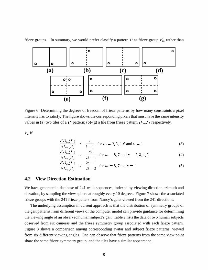
frieze groups. In summary, we would prefer classify a patternP as frieze groupFm rather than
(f) (g)
(a) (b)
(e)
(c) (d)
Figure 6: Determining the degrees of freedom of frieze patterns by how many constraints a pixel
intensity has to satisfy. The figure shows the corresponding pixels that must have the same intensity
values in (a) two tiles of aP1 pattern; (b)-(g) a tile from frieze patternP2:::P7 respectively.
Fn if
SDm(P )
SDn(P )<
t
t� 1; for m = 2; 3; 4; 6 andn = 1 (3)
SDm(P )
SDn(P )<
2t
2t� 1; for m = 5; 7 andn = 2; 3; 4; 6 (4)
SDm(P )
SDn(P )<
2t+ 1
2t� 2; for m = 5; 7andn = 1 (5)
4.2 View Direction Estimation
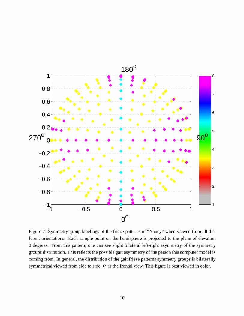
We have generated a database of 241 walk sequences, indexed by viewing direction azimuth and
elevation, by sampling the view sphere at roughly every 10 degrees. Figure 7 shows the associated
frieze groups with the 241 frieze patters from Nancy’s gaits viewed from the 241 directions.
The underlying assumption in current approach is that the distribution of symmetry groups of
the gait patterns from different views of the computer model can provide guidance for determining
the viewing angle of an observed human subject’s gait. Table 2 lists the data of two human subjects
observed from six cameras and the frieze symmetry group associated with each frieze pattern.
Figure 8 shows a comparison among corresponding avatar and subject frieze patterns, viewed
from six different viewing angles. One can observe that frieze patterns from the same view point
share the same frieze symmetry group, and the tiles have a similar appearance.
9
1
2
3
4
5
6
7
8
−1 −0.5 0 0.5 1−1
−0.8
−0.6
−0.4
−0.2
0
0.2
0.4
0.6
0.8
1
0o
90o
180o
270o
Figure 7: Symmetry group labelings of the frieze patterns of “Nancy” when viewed from all dif-
ferent orientations. Each sample point on the hemisphere is projected to the plane of elevation
0 degrees. From this pattern, one can see slight bilateral left-right asymmetry of the symmetry
groups distribution. This reflects the possible gait asymmetry of the person this computer model is
coming from. In general, the distribution of the gait frieze patterns symmetry groups is bilaterally
symmetrical viewed from side to side.0o is the frontal view. This figure is best viewed in color.
10
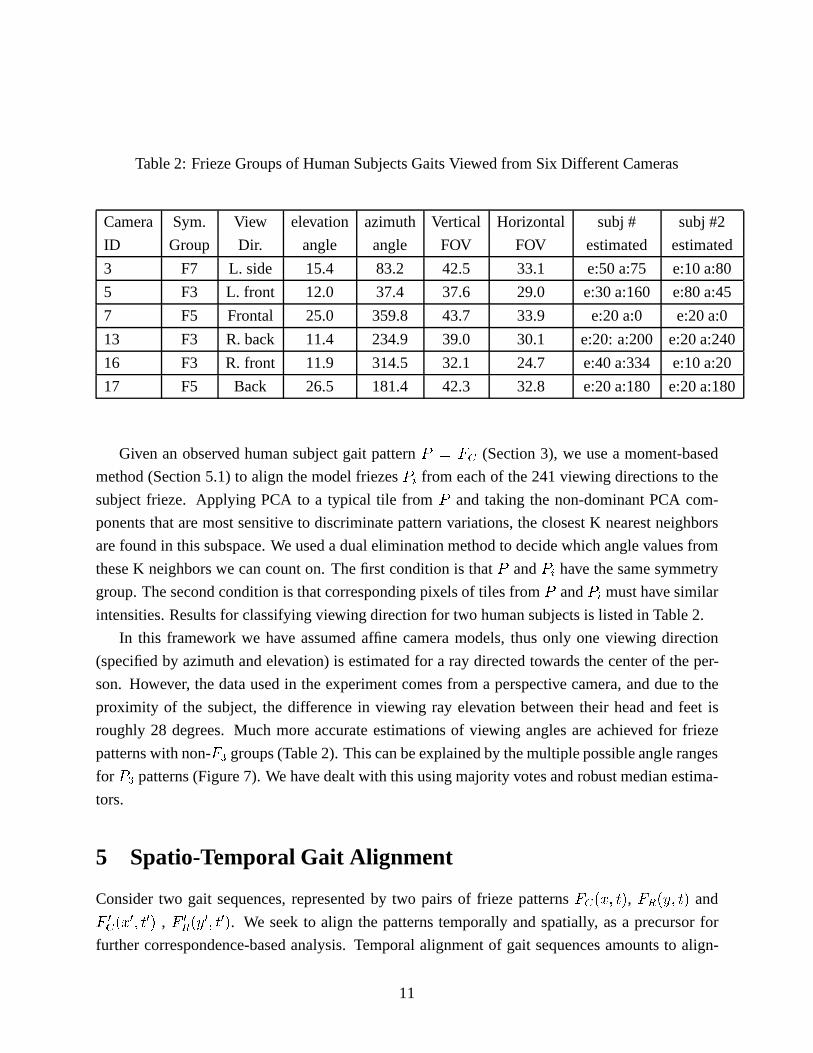
Table 2: Frieze Groups of Human Subjects Gaits Viewed from Six Different Cameras
Camera Sym. View elevation azimuth Vertical Horizontal subj # subj #2
ID Group Dir. angle angle FOV FOV estimated estimated
3 F7 L. side 15.4 83.2 42.5 33.1 e:50 a:75 e:10 a:80
5 F3 L. front 12.0 37.4 37.6 29.0 e:30 a:160 e:80 a:45
7 F5 Frontal 25.0 359.8 43.7 33.9 e:20 a:0 e:20 a:0
13 F3 R. back 11.4 234.9 39.0 30.1 e:20: a:200 e:20 a:240
16 F3 R. front 11.9 314.5 32.1 24.7 e:40 a:334 e:10 a:20
17 F5 Back 26.5 181.4 42.3 32.8 e:20 a:180 e:20 a:180
Given an observed human subject gait patternP = FC (Section 3), we use a moment-based
method (Section 5.1) to align the model friezesPi from each of the 241 viewing directions to the
subject frieze. Applying PCA to a typical tile fromP and taking the non-dominant PCA com-
ponents that are most sensitive to discriminate pattern variations, the closest K nearest neighbors
are found in this subspace. We used a dual elimination method to decide which angle values from
these K neighbors we can count on. The first condition is thatP andPi have the same symmetry
group. The second condition is that corresponding pixels of tiles fromP andPi must have similar
intensities. Results for classifying viewing direction for two human subjects is listed in Table 2.
In this framework we have assumed affine camera models, thus only one viewing direction
(specified by azimuth and elevation) is estimated for a ray directed towards the center of the per-
son. However, the data used in the experiment comes from a perspective camera, and due to the
proximity of the subject, the difference in viewing ray elevation between their head and feet is
roughly 28 degrees. Much more accurate estimations of viewing angles are achieved for frieze
patterns with non-F3 groups (Table 2). This can be explained by the multiple possible angle ranges
for P3 patterns (Figure 7). We have dealt with this using majority votes and robust median estima-
tors.
5 Spatio-Temporal Gait Alignment
Consider two gait sequences, represented by two pairs of frieze patternsFC(x; t), FR(y; t) and
F 0C(x0; t0) , F 0
R(y0; t0). We seek to align the patterns temporally and spatially, as a precursor for
further correspondence-based analysis. Temporal alignment of gait sequences amounts to align-
11

Figure 8: The view of the frieze patterns from six different angels. Left: Avatar Nancy. Middle:
subject # 1. Right: subject # 2.
ing frieze patterns horizontally, thereby determining a mapping between time variablest and t0.
Temporal alignment of frieze patterns is greatly simplified by the periodic nature of the patterns,
allowing us to use simple periodic signal analysis in place of expensive dynamic time warping pro-
cedures. Spatial alignment means finding a mapping between pixel locations(x; y) in sequence 1
and(x0; y0) in sequence 2. We restrict this to a four parameter affine mapping, and show that it can
be found by aligning the corresponding row and column friezes along their vertical dimensions.
5.1 Moment-Based Gait Alignment
It is well known that the first and second moments of two binary silhouettes can be used to de-
termine an affine transformation that coarsely aligns them, and that some of the moments of a
silhouette image can be computed from its row and column projections [1]. This forms the basis
of our gait alignment method.
First, we generalize the concept of moments of a binary image to cover a time series of moments
computed from a sequence of binary images. Define amoment sequenceas
mij(t) =Xx
Xy
xiyjb(x; y; t)
which is a sequence of single-frame binary silhouette moments, indexed by time. Note thatm00(t)
12
is just the area of the binary silhouette over time, while�x(t) � m10(t)=m00(t) and �y(t) �
m01(t)=m00(t) are the coordinates of the silhouette centroid over time. Similarly, define acen-
tral moment sequenceas
�ij(t) =Xx
Xy
(x� �x(t))i(y � �y(t))jb(x; y; t)
which is a sequence of moments measured after translating each silhouette so that its centroid is at
the origin. The second central moments measure the spread of silhouette pixels about the centroid,
and can be used to derive the principal axis of the silhouette shape.
Since we have summarized each sequence of silhouettes as frieze patterns, we are concerned
only with moments that can be computed from row and column projections. For example, consider
silhouette area
m00(t) =Xx
Xy
b(x; y; t) =Xx
Xy
b(x; y; t)
!=Xx
fC(x; t)
which can thus be computed from the frieze pattern as well as the original silhouette sequence.
Any moment sequencemij(t) or central moment sequence�ij(t) with eitheri or j (or both) equal
to zero can be computed from frieze patternsfC(t) andfR(t). In the present case, we will use
m00(t), m10(t), m10(t), �20(t), and�02(t). Note that the second central moment�11(t) can not be
determined from the two frieze patterns, and we will therefore not be able to adjust skew or prin-
ciple axis rotation when aligning silhouette shapes using friezes alone. Difference in skew angle
is not an issue when matching silhouettes seen from nearby viewpoints. Requiring the principle
axes to be the same means that we are assuming the roll angles of the camera are also similar.
Should an application require these extra degrees of freedom, they could be computed by included
a third frieze formed by silhouette projection along a 45 degree diagonal axis, from which the
cross-momentsm11(t) and�11(t) can be measured [1].
We now present an algorithm for moment-based gait alignment. To a first approximation, the
temporal alignment between the two periodic gait sequences can be represented ast0 = � t + �,
where� corrects for the relative stride frequency and� corrects for the relative phase difference
(position within a stride). The average stride frequency of each gait sequence is found by taking
signalm00(t), “whitening” it by subtracting its mean and dividing by its standard deviation, then
autocorrelating to find peaks occurring at a fundamental frequency. From some viewpoints this is
the stride frequency, and from others it is half the stride frequency (e.g. a bipedal gait viewed from
the side looks self-similar halfway through a full stride). Whether the autocorrelation ofm00(t)
yields peaks at half the stride frequency is viewpoint dependent, and can be calibrated using the
walking avatar model. Letf andf 0 denote the average frequencies of the two gait sequences,
13
computed fromm00 of sequence 1 andm000 of sequence 2. Then� = f 0=f . To determine the
relative phase, we crop a subsequence of temporal lengthf from m00(t), expand or contract it by
�, then correlate withm000. The average lag of prominent peaks of the correlation result determines
the relative phase. There may be a two-fold ambiguity in the phase from those viewpoints for
which the autocorrelation ofm00 yields peaks at half the stride frequency. For people close to the
camera, the perspective effects are usually enough to uniquely determine the phase. For people far
away, however, it can be difficult to distinguish between left foot forward or right foot forward on
the basis of silhouette moment information alone.
After determining the temporal mapping betweent and t0, we now align the frieze patterns
spatially. Given the moments that we can compute from frieze patterns, we determine the two
translations and two scale factors that relate(x; y) and(x0; y0) for corresponding time steps in the
two sequences. Dropping the time variables from the notation, this affine transformation is found
to be 24 x0
y0
35 =
2664r
�020m00
�20m000
0
0r
�002m00
�02m000
377524 x � m10=m00
y � m01=m00
35 +
24 m0
10=m000
m001=m
000
35
Whether to allow both scale factors to vary independently for each time step, to enforce their
ratio to be constant, to compute a temporal average for each, or other variations depends on the
application and on the amount of noise one can expect in the underlying silhouette data.
5.2 Applications of Gait Alignment
We illustrate the utility of moment-based frieze alignment with two applications. The first involves
comparing frieze tiles to classify a walking person’s identity given a prior training set of gait data.
The second application concerns matching a walking humanoid model to gait silhouette data from
a real person, in order to locate specific body parts in each frame.
5.2.1 Human Identification
Given a dataset of gait sequences collected from one camera viewpoint, we want to analyze a new
sequence to determine which person it is. Our approach is to create row and column silhouette
projection friezes for each sequence, warp them all temporally to a canonical frequency and phase
using the first half of the above alignment procedure, then cut out several tiles corresponding to
individual strides from each sequence. These aligned frieze tiles are compared using normalized
correlation, and subject classification is performed by nearest neighbor matching on correlation
scores. This approach implicitly captures biometric shape cues such as body height/width ratio,
14
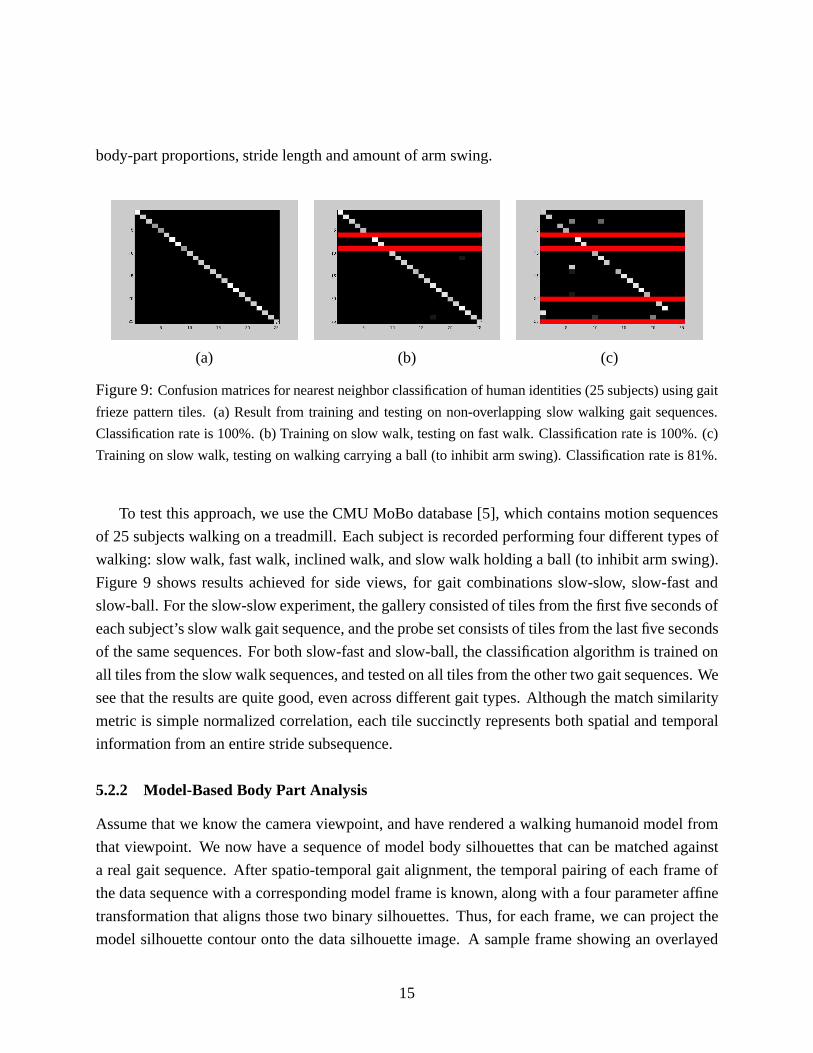
body-part proportions, stride length and amount of arm swing.
(a) (b) (c)
Figure 9:Confusion matrices for nearest neighbor classification of human identities (25 subjects) using gait
frieze pattern tiles. (a) Result from training and testing on non-overlapping slow walking gait sequences.
Classification rate is 100%. (b) Training on slow walk, testing on fast walk. Classification rate is 100%. (c)
Training on slow walk, testing on walking carrying a ball (to inhibit arm swing). Classification rate is 81%.
To test this approach, we use the CMU MoBo database [5], which contains motion sequences
of 25 subjects walking on a treadmill. Each subject is recorded performing four different types of
walking: slow walk, fast walk, inclined walk, and slow walk holding a ball (to inhibit arm swing).
Figure 9 shows results achieved for side views, for gait combinations slow-slow, slow-fast and
slow-ball. For the slow-slow experiment, the gallery consisted of tiles from the first five seconds of
each subject’s slow walk gait sequence, and the probe set consists of tiles from the last five seconds
of the same sequences. For both slow-fast and slow-ball, the classification algorithm is trained on
all tiles from the slow walk sequences, and tested on all tiles from the other two gait sequences. We
see that the results are quite good, even across different gait types. Although the match similarity
metric is simple normalized correlation, each tile succinctly represents both spatial and temporal
information from an entire stride subsequence.
5.2.2 Model-Based Body Part Analysis
Assume that we know the camera viewpoint, and have rendered a walking humanoid model from
that viewpoint. We now have a sequence of model body silhouettes that can be matched against
a real gait sequence. After spatio-temporal gait alignment, the temporal pairing of each frame of
the data sequence with a corresponding model frame is known, along with a four parameter affine
transformation that aligns those two binary silhouettes. Thus, for each frame, we can project the
model silhouette contour onto the data silhouette image. A sample frame showing an overlayed
15
model contour found through automatic gait sequence alignment is shown in Figure 10A. The
aligned model contour does not exactly coincide with the person’s body outline due to a variety
of factors, including differences in body shape and joint angle kinematics between the avatar and
the human being (e.g. body proportions and amount of arm swing), as well as small differences
in camera perspective between the model and data viewpoints. However, note that the overall
temporal and spatial alignment is quite good, in the sense that the aligned model tells us what body
parts should be visible, and roughly where they should appear in the image. More importantly,
we know which body parts are occluded and should not be considered for further analysis in this
frame.
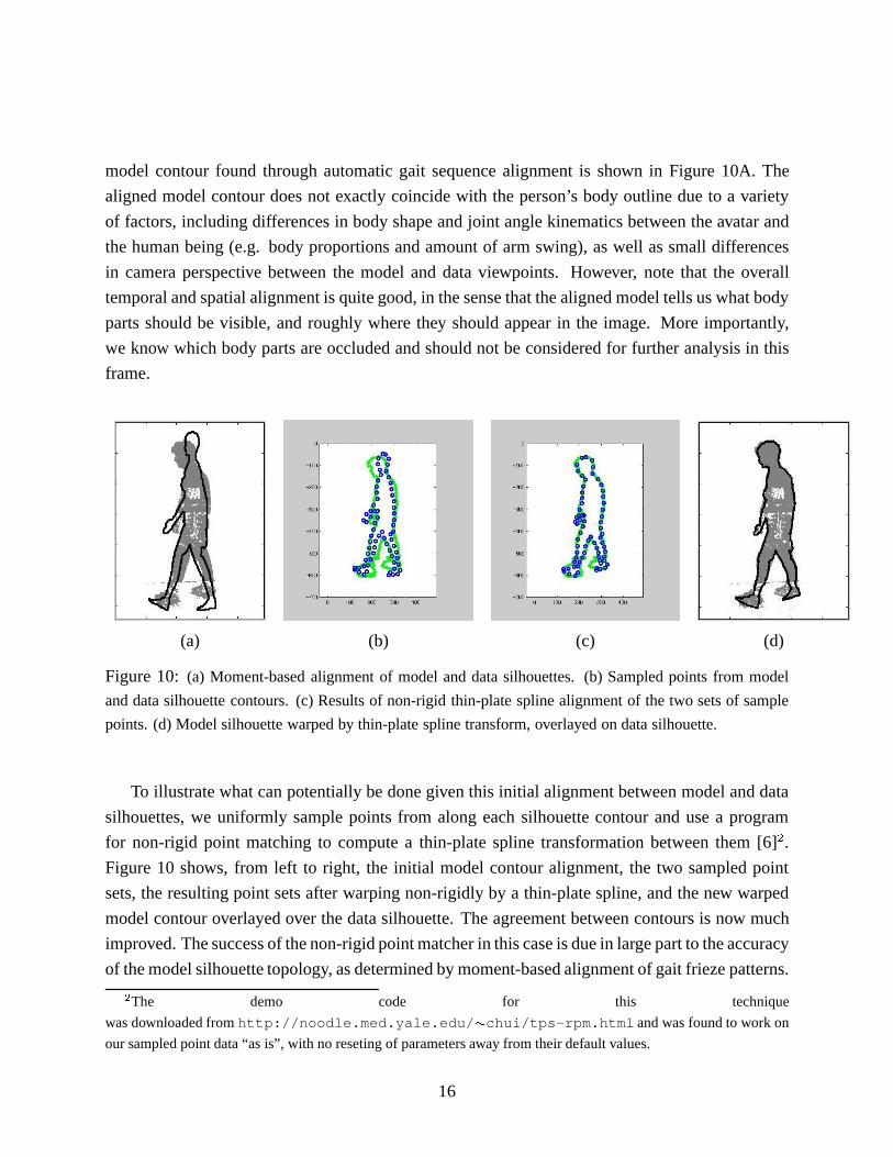
(a) (b) (c) (d)
Figure 10: (a) Moment-based alignment of model and data silhouettes. (b) Sampled points from model
and data silhouette contours. (c) Results of non-rigid thin-plate spline alignment of the two sets of sample
points. (d) Model silhouette warped by thin-plate spline transform, overlayed on data silhouette.
To illustrate what can potentially be done given this initial alignment between model and data
silhouettes, we uniformly sample points from along each silhouette contour and use a program
for non-rigid point matching to compute a thin-plate spline transformation between them [6]2.
Figure 10 shows, from left to right, the initial model contour alignment, the two sampled point
sets, the resulting point sets after warping non-rigidly by a thin-plate spline, and the new warped
model contour overlayed over the data silhouette. The agreement between contours is now much
improved. The success of the non-rigid point matcher in this case is due in large part to the accuracy
of the model silhouette topology, as determined by moment-based alignment of gait frieze patterns.
2The demo code for this technique
was downloaded fromhttp://noodle.med.yale.edu/ �chui/tps-rpm.html and was found to work on
our sampled point data “as is”, with no reseting of parameters away from their default values.
16
More examples are shown in Figure 11. Model-based gait analysis using frieze patterns offers an
efficient alternative to kinematic body part tracking for determining the location of individual body
parts in each frame of a gait sequence.
6 Summary
We have presented a periodic pattern representation for analyzing gait sequences. Silhouette row
and column projections are stacked over time to form frieze patterns that can be analyzed using the
mathematical theory of symmetry groups. With the help of a walking humanoid avatar, we have
studied the correlation between the seven frieze symmetry groups and gait viewing direction, and
have had to develop practical techniques for classifying imperfect frieze patterns. Our future work
will explore methods for more efficient and accurate viewpoint estimation from frieze patterns, and
extend our mathematical methods for imperfect pattern analysis to patterns that are periodic along
two dimensions. We have also presented a moment-based method for aligning frieze gait patterns
both temporally and spatially. The method has applications in determining human identity from
gait biometrics, and it provides an efficient alternative to frame-by-frame tracking approaches for
locating and delineating body parts. We plan to apply this technique within a multi-camera motion
capture system to perform 3D body reconstruction and motion analysis for human identification
and sports entertainment.
17
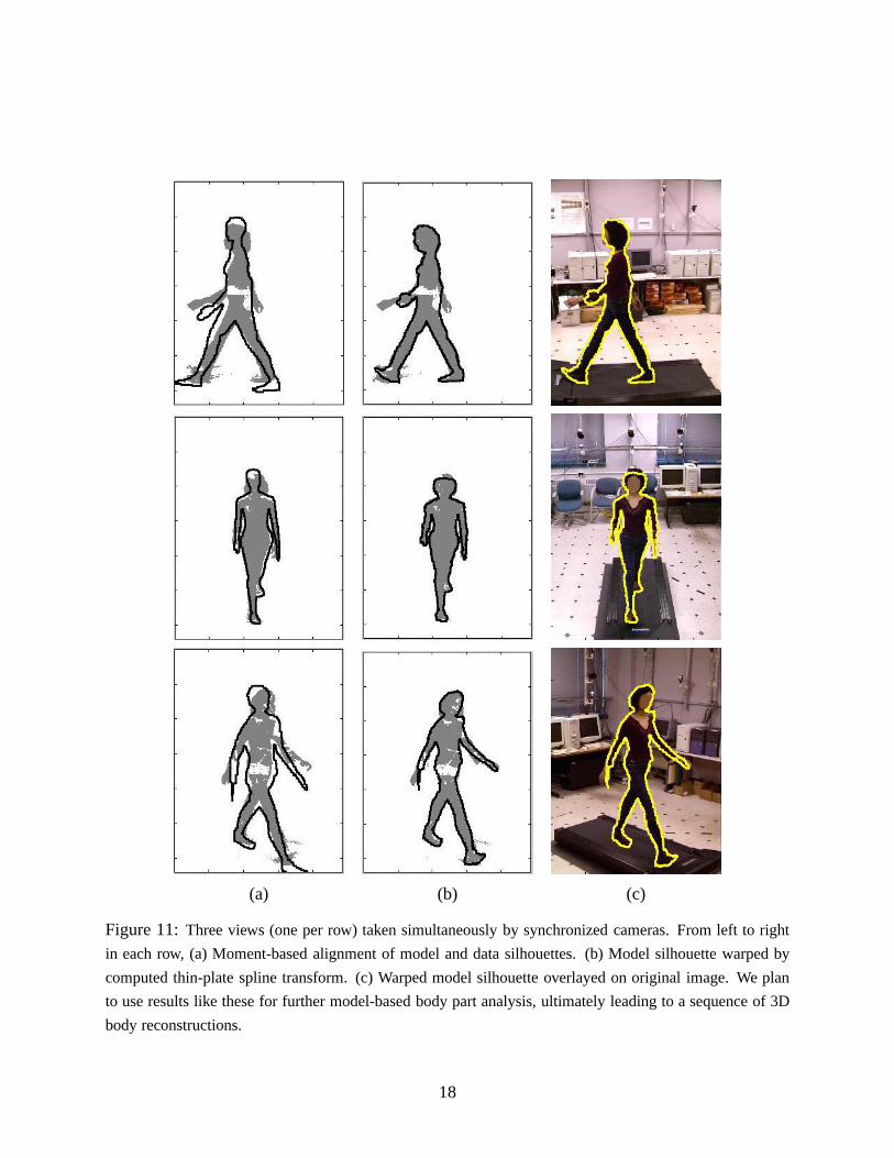
(a) (b) (c)
Figure 11:Three views (one per row) taken simultaneously by synchronized cameras. From left to right
in each row, (a) Moment-based alignment of model and data silhouettes. (b) Model silhouette warped by
computed thin-plate spline transform. (c) Warped model silhouette overlayed on original image. We plan
to use results like these for further model-based body part analysis, ultimately leading to a sequence of 3D
body reconstructions.
18
References
[1] B.K.P.Horn.Robot Vision. MIT Press, 1986.
[2] C. Bregler and J. Malik. Tracking people with twists and exponential maps. InProc. IEEE
Computer Vision and Pattern Recognition, pages 8–15, 1998.
[3] T.J. Cham and J.M. Rehg. A multiple hypothesis approach to figure tracking. InProc. IEEE
Computer Vision and Pattern Recognition, pages II:239–245, 1999.
[4] R. Cutler and L.. Davis. Robust real-time periodic motion detection, analysis, and applica-
tions. IEEE Transaction on Pattern Analysis and Machine Intelligence, To Appear.
[5] R. Gross and J. Shi. The CMU motion of body (MoBo) database. Technical Report CMU-
RI-TR-01-18, Robotics Institute, Carnegie Mellon University, 2001.
[6] H.Chui and A.Rangarajan. A new algorithm for non-rigid point matching.IEEE Computer
Vision and Pattern Recognition, pages 44–51, 2000.
[7] D. Hogg. Model-based vision: A program to see a walking person.Image and Vision Com-
puting, 1(1):5–20, 1983.
[8] K. Kanatani. Statistical Optimization for Geometric Computation : Theory and Practice
(Machine Intelligence and Pattern Recognition, Vol 18). North-Holland, 1996.
[9] K. Kanatani. Comments on ”Symmetry as a Continuous Feature.IEEE Transactions on
Pattern Analysis and Machine Intelligence, 19(3):246–247, 1997.
[10] J.J. Little and J.E. Boyd. Recognizing people by their gait: The shape of motion.Videre,
1(2):xx–yy, 1998.
[11] F. Liu and R. W Picard. Finding periodicity in space and time. InIEEE International Con-
ference on Computer Vision (ICCV), 1998.
[12] Y. Liu and R. T. Collins. A Computational Model for Repeated Pattern Perception us-
ing Frieze and Wallpaper Groups. InComputer Vision and Pattern Recognition Con-
ference, pages 537–544, Los Alamitos, CA, June 2000. IEEE Computer Society Press.
(http://www.ri.cmu.edu/pubs/pub3302.html).
[13] Y. Liu and R.T. Collins. Frieze and wallpaper symmetry groups classification under affine
and perspective distortion. Technical Report CMU-RI-TR-98-37, The Robotics Institute,
Carnegie Mellon University, Pittsburgh, PA, 1998.
19
[14] S.A. Niyogi and E.H. Adelson. Analyzing and recognizing walking figures in xyt. InProc.
IEEE Computer Vision and Pattern Recognition, pages 469–474, 1994.
[15] S.M. Seitz and C.R. Dyer. View-invariant analysis of cyclic motion.International Journal of
Computer Vision, 25:1–23, 1997.
[16] H. Zabrodsky, S. Peleg, and D. Avnir. Symmetry as a continuous feature.IEEE Transactions
on Pattern Analysis and Machine Intelligence, 17(12):1154–1165, December 1995.
20