G8JNJ - Broadband Terminated Vee antenna
8
Broadband Terminated Vee antenna Preliminary observations Article appeared in QST November 1995, (available online to ARRL members). Is a travelling wave antenna, which has a constant current distribution along its length. Approx 120ft long with 30ft support pole in centre. Fed via 9:1 Unun with second 9:1 Unun at far end feeding 50 ohm termination. A termination resistor at the far end absorbs reflected wave along the antenna Counterpoise wire running under Vee connects the ground posts at each end. Some directivity at HF frequencies so can swap feed and load between ends. Main problem was in constructing 9:1 Unun with correct size wire for windings. Winding with wrong wire size resulted in poor impedance transformation and high through loss. Optimised with 8 trifilar turns of 0.6mm dia stranded wire (with 1.2mm outer dia PVC insulation) wound on FT240-61 core. Finally achieved good bandwidth 1.8 to 30MHz with less than 0.5dB loss. Graph showing 9:1 Unun secondary impedance
description
G8JNJ Vee antenna
Transcript of G8JNJ - Broadband Terminated Vee antenna
Broadband Terminated Vee antenna
Preliminary observations Article appeared in QST November 1995, (available online to ARRL members). Is a travelling wave antenna, which has a constant current distribution along its length. Approx 120ft long with 30ft support pole in centre. Fed via 9:1 Unun with second 9:1 Unun at far end feeding 50 ohm termination. A termination resistor at the far end absorbs reflected wave along the antenna Counterpoise wire running under Vee connects the ground posts at each end. Some directivity at HF frequencies so can swap feed and load between ends. Main problem was in constructing 9:1 Unun with correct size wire for windings. Winding with wrong wire size resulted in poor impedance transformation and high through loss. Optimised with 8 trifilar turns of 0.6mm dia stranded wire (with 1.2mm outer dia PVC insulation) wound on FT240-61 core.
Finally achieved good bandwidth 1.8 to 30MHz with less than 0.5dB loss. Graph showing 9:1 Unun secondary impedance

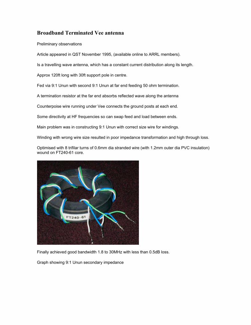
Graph showing 9:1 Unun though loss
Second attempt at Unun, further optimised with 6 trifilar turns of 18AWG silver plated stranded wire. PTFE insulation, 1.85mm outer dia (CPC part number CB10433) wound on FT240-61 core.

Graph showing 9:1 Unun secondary impedance
Graph showing 9:1 Unun though loss
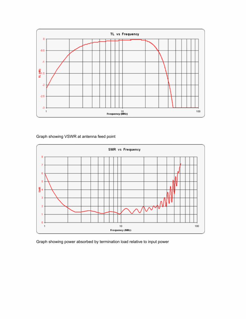
Graph showing VSWR at antenna feed point
Graph showing power absorbed by termination load relative to input power

I also used the antenna to transmit on each of the Amateur bands between 1.9MHz and 50MHz. I measured the received field strength with a remote controlled Icom PCR-1000 receiver connected to a Datong active antenna. This was located on a building roof approx 20m AGL at approx 2 miles away from the transmit site. I used a 100ft doublet fed via 450 ohm ladder line and matched with a CG-3000 auto-atu at the base as the reference antenna. Note that the directivity of each antenna should be taken into consideration when examining these results. I moved one end of the Vee to three different positions. Graph showing gain relative to 100ft doublet

V1 is firing N-S, V2 is reversed firing S-N and V3 is like V1 but with one leg moved 30 degrees in order to try and gauge the directivity of the antenna.

Next some EZNEC modeling EZNEC plot of pattern at 14.1MHz
Source at point 3 - not very good, I would have expected a much cleaner pattern.

Not too good on any of the other bands either
Further experiments to be tried include modeling as sloping wire © M. Ehrenfried - G8JNJ - V1.2 - 8/06/2009 www.g8jnj.webs.com