G4HUP Panoramic Adaptor Installation –...
9
G4HUP © 2014 PAT Install FT897 5 Aug 2014 G4HUP Panoramic Adaptor Installation – FT897 These instruction cover installation of the PAT board in the 1st IF of the FT897 (68.33MHz), and also for installation to serve a second independent receiver function. Note that these options are mutually exclusive – one PAT board can be an IF tap OR a 2 nd Rx only! See my Second Rx document if you are not sure about the differences. The FT897 uses a common IF for transmit and receive, so some care is needed in the connection point to avoid the possibility of high level signals into your SDR during transmit. Following the connections given here will avoid that risk. 1 Build and test the PAT kit – use an 8 to 10v supply and you should measure a gain of approx 1dB at 70MHz. For 2 nd Rx use, omit the LPF and replace L1 and L3 with 0R link resistors. 2 Remove top cover from FT897 (8 screws). 3 There is no convenient location for a socket on the rear panel without some metal work. I chose to locate an SMA socket (2 hole type) mounted vertically across a ventilation slot – see section below. 4 The PAT board mounts conveniently on top of the PLL Unit - see Fig 1. From this position, the input and output connections are just a short run, and no internal adjustments are obstructed by the mounting position. Fig 1 – Mounting position of the PAT board in FT897 – note that the PAT input is to the left in this picture 5 The PAT board is held in place by double sided tape, so can easily be removed should it become necessary. It is recommended to use DS tape to hold a layer of card to the screening can, then a second piece of DS tape to hold the PAT board in place.
Transcript of G4HUP Panoramic Adaptor Installation –...
G4HUP © 2014
PAT Install FT897 5 Aug 2014
G4HUP Panoramic Adaptor Installation – FT897 These instruction cover installation of the PAT board in the 1st IF of the FT897 (68.33MHz), and
also for installation to serve a second independent receiver function. Note that these options are mutually exclusive – one PAT board can be an IF tap OR a 2nd Rx only! See my Second Rx
document if you are not sure about the differences.
The FT897 uses a common IF for transmit and receive, so some care is needed in the connection
point to avoid the possibility of high level signals into your SDR during transmit. Following the connections given here will avoid that risk.
1 Build and test the PAT kit – use an 8 to 10v supply and you should measure a gain of
approx 1dB at 70MHz. For 2nd Rx use, omit the LPF and replace L1 and L3 with 0R link resistors.
2 Remove top cover from FT897 (8 screws). 3 There is no convenient location for a socket on the rear panel without some metal
work. I chose to locate an SMA socket (2 hole type) mounted vertically across a
ventilation slot – see section below. 4 The PAT board mounts conveniently on top of the PLL Unit - see Fig 1. From this
position, the input and output connections are just a short run, and no internal adjustments are obstructed by the mounting position.
Fig 1 – Mounting position of the PAT board in FT897 – note that the PAT input is to the left in this picture
5 The PAT board is held in place by double sided tape, so can easily be removed
should it become necessary. It is recommended to use DS tape to hold a layer of card to the screening can, then a second piece of DS tape to hold the PAT board in
place.

G4HUP © 2014
PAT Install FT897 5 Aug 2014
6 For 1st IF use, the RF input to the board comes from output side of the IF filter, after
the diode T/R switch. The actual connection is taken from the centre connection of T1026 secondary – see Figs 2 and 3. This is outside the common T/R path, so only
Rx signals should be present at this point.
Fig 2 – Connection points for RF input and RxB – extract from FT897 Service
Manual
Fig 3 – connection of RG178 coax to centre pin of T1026. Note that braid is not connected, and filter layout is different to the Manual information.
G4HUP © 2014
PAT Install FT897 5 Aug 2014
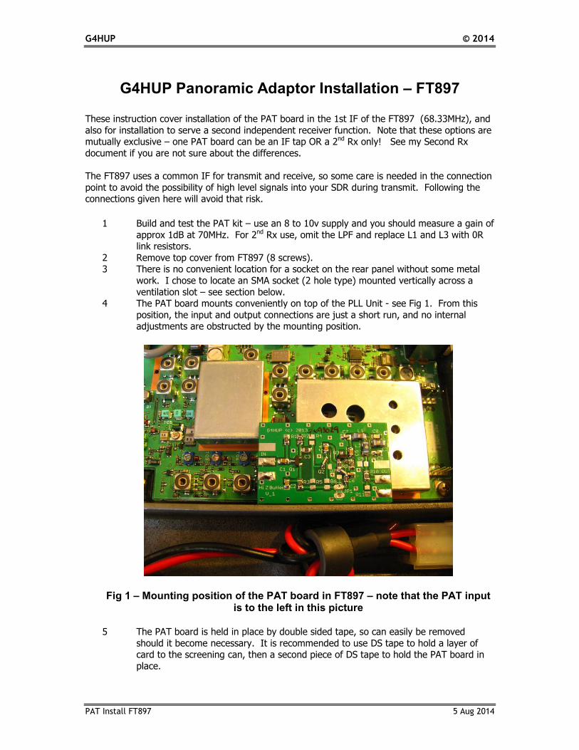
7 Prepare a 7cm length of RG178 cable to make the connection between T1026 and
the PAT input, and a 9cm length to make the output connection to the SMA socket, using the dimensions given in Table 1 and Fig 9. Do not pigtail the ends, but make
them off as in Fig 4. See also details at the end of this note.
Fig 4 – RG178 cable termination
Hold the SMA socket in place with a self tapping screw in the lower mounting hole. Temporarily
remove the Optional Reference Unit if installed.
Connect the end of the output cable to the centre of the SMA, and solder the braid to the solder
tag.
Loop the cable round and terminate on the output connections of the PAT board, as in Fig 4.
Take the input cable and carefully solder the free end to the centre connection on T1026 – this is
on the rearward facing side of the screening can of T1026. Care is needed as the can will very easily take solder, with the potential for inadvertent short circuits!
Loop the cable round and terminate on the input of the PAT board.
Strip 1mm (or less) off the ends of the 65mm red wire. Solder the free end to the end of R1302, as shown in Fig 2 to pick up the switched 8v RxB supply. You can see a picture of this in Fig 5.
It is easier to connect to the end of the resistor, rather than try to solder to the via. DO NOT connect to the via that appears by itself slightly forward of R1302 – this does not carry RxB!
Fig 6 shows the completed installation, with the PAT PCB mounted on top of the PLL Unit, and
with the 1st mixer in the can to its right. To the left of the PLL Unit is the High Stability
Reference option, which only just clears the PAT output connections in this instance.
8 Replace the cover, connect and test.

G4HUP © 2014
PAT Install FT897 5 Aug 2014
Fig 5 – RxB connection at R1302
Fig 6 – Completed installation for 1st IF tap For Second Receiver Function, install as above, except for the connection to the FT897 signal
path. This should be connected to the main RF Rx feed into the Main Unit, at J3 in the centre of the PCB – see Fig 7 below. Be careful not to short circuit the connector or damage the grey coax
lead while soldering. Note that the outer of the PAT input coax is not grounded at the J3 end.

G4HUP © 2014
PAT Install FT897 5 Aug 2014
Note that for full coverage when using the 2nd Receiver function, the PAT board must not have its
LPF present (L1-3, C7-9), or you will not be able to display the 2m and 70cm bands on the SDR. Remove the LPF (if fitted) and replace L1 and L3 with 0R resistors or short wire links.
Fig 7 – Connection detail for the PAT input for Second Receiver Application.
Installing an SMA socket on the FT897 Rear Panel
There are two ventilation slots between the power connector and the CAT socket at the
top of the rear panel. An SMA, or similar small socket, fits neatly across the slot, and
passes through for a connection to be made from inside the rig. This exercise needs care,
as you will have to drill into the rear panel – take precautions to avoid swarf falling into
the rig.
The best location for the socket is about half way across the second slot – not where I
have it in Fig 8 below! The Reference Oscillator option is located immediately behind
the panel as I have it marked out, and a much better location for the socket is in the right
hand slot, just a little to the right of where the ground symbol is shown.
The upper hole can be drilled M2.5 clear (drill No 39 US) right through the panel. The
lower hole aligns with the internal chassis casting, and so will be blind. A shorter M2.5
screw is supplied in the installation kit. Drill a blind hole using M2.2 or M2.3 drill (No
44 US). This hole needs to be approx 4mm deep, but greater depth will not be an issue.
The screw will then cut its own threads into the relatively soft aluminium of the panel
casting.
Once the mechanical work has been completed, ensure that all swarf and metallic dust is
cleared from the radio, and fit the socket. On the inside of the panel, fit a solder tag
under the nut.

G4HUP © 2014
PAT Install FT897 5 Aug 2014
Fig 8 – Rear panel marked ready for drilling note - it is recommended that you place the socket about half way
across the second slot as this makes the internal connection easier.
Terminating PTFE Coax cables These instructions could be used, with suitable modification, to correctly terminate any of the
PTFE coax cables, such as RG142, RG178, RG188, RG196, RG316, etc. The termination method ensures good quality RF connections up to higher microwave frequencies
Using a scalpel, cut the sheath back at the required length.
With a hot iron, tin the exposed braid fully. With the scalpel, score around the point where the braid must end.
Use long-nose pliers to bend the end of the coax outside the score line – the braid will crack on the score line and the excess can be slid off the dielectric.
Strip the dielectric to reveal the inner.
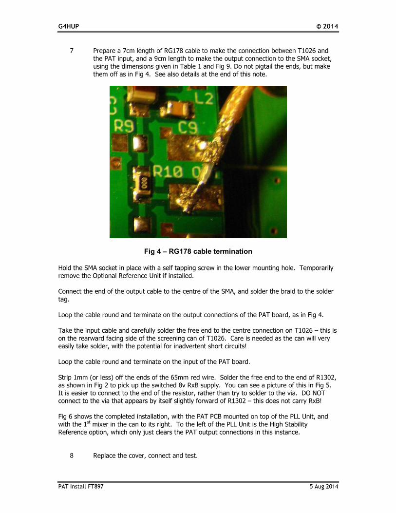
Fig 9 shows a correctly terminated cable installed in an FT817, and you can see another example
in Fig 4 above.
G4HUP © 2014
PAT Install FT897 5 Aug 2014
Fig 9 – Correct method of termination for the RG178 cable
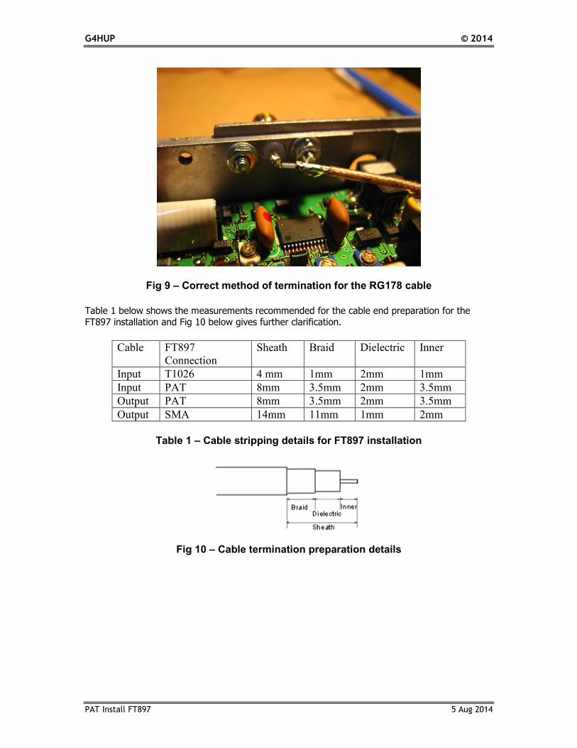
Table 1 below shows the measurements recommended for the cable end preparation for the FT897 installation and Fig 10 below gives further clarification.
Cable FT897
Connection
Sheath Braid Dielectric Inner
Input T1026 4 mm 1mm 2mm 1mm
Input PAT 8mm 3.5mm 2mm 3.5mm
Output PAT 8mm 3.5mm 2mm 3.5mm
Output SMA 14mm 11mm 1mm 2mm
Table 1 – Cable stripping details for FT897 installation
Fig 10 – Cable termination preparation details
G4HUP © 2014
PAT Install FT897 5 Aug 2014
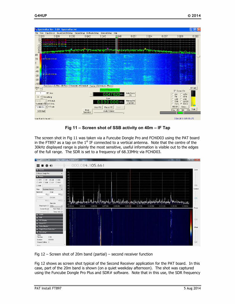
Fig 11 – Screen shot of SSB activity on 40m – IF Tap
The screen shot in Fig 11 was taken via a Funcube Dongle Pro and FCHiD03 using the PAT board
in the FT897 as a tap on the 1st IF connected to a vertical antenna. Note that the centre of the 30kHz displayed range is plainly the most sensitive, useful information is visible out to the edges
of the full range. The SDR is set to a frequency of 68.33MHz via FCHiD03.
Fig 12 – Screen shot of 20m band (partial) – second receiver function
Fig 12 shows as screen shot typical of the Second Receiver application for the PAT board. In this case, part of the 20m band is shown (on a quiet weekday afternoon). The shot was captured
using the Funcube Dongle Pro Plus and SDR# software. Note that in this use, the SDR frequency

G4HUP © 2014
PAT Install FT897 5 Aug 2014
must be set to the band being monitored. On the FT897, due to the block band pass filters that
Yaesu have used in the Rx path, you can monitor 30, 20 or 17m on the SDR, at the same time as being on any of those bands with the rig – and of course, using the SDR you can demodulate any
of those signals too.