G46 VENTED GAS LOG SET - American Fire Glass
48
1 REV 14 - 2008031030 L-A2-215 Robert H. Peterson Co. • 14724 East Proctor Avenue • City of Industry, CA 91746 Robert H. Peterson Co. • 14724 East Proctor Avenue • City of Industry, CA 91746 Robert H. Peterson Co. • 14724 East Proctor Avenue • City of Industry, CA 91746 This gas log set is to be installed only in a solid-fuel burning fireplace with a working flue and constructed of noncombustible material. The installation, including provisions for combustion and ventilation air must conform with the National Fuel Gas Code, ANSI Z223.1/ NFPA 54, or the CSA B149.1, Natural Gas and Propane Installation Code, and applicable local building codes. A damper clamp, which must be permanently installed, is included to maintain the minimum permanent vent opening and to prevent full closure of the damper. The chimney damper MUST be fully opened when burning the unit. The unit is designed to burn with yellow flames; thus adequate ventilation is absolutely necessary. To comply with certification, listings, and building code acceptances, and for safe operation and proper performance of this gas log set, you must use ONLY Peterson Real Fyre parts, decorative media, and accessories. Use of any other controls, parts, or accessories not designed for use with Real Fyre gas log set is prohibited. This will void all warranties, certifications, listings, and building code approvals, and may cause property damage, personal injury, or loss of life. Peterson will not be liable for any damages caused by this misuse. *Note: Solid-fuels shall not be burned in a fireplace where a decorative appliance is installed. FOR INSTALLATION IN SOLID-FUEL BURNING FIREPLACES* IMPORTANT: READ THESE INSTRUCTIONS CAREFULLY BEFORE STARTING INSTALLATION OF THE UNIT. DESIGN CERTIFIED to Vented Decorative Appliance ANSI Z21.60-2017 CSA 2.26-2017 INSTALLER: Leave this manual with the appliance. CONSUMER: Retain this manual for future reference. Regulated burner system for use w/ propane or natural gas INSTALLATION & OWNER’S MANUAL G46 VENTED GAS LOG SET Burner Systems: G46- ** (P) G46- ** -02(M)(P) G46- ** -11(M)(P) G46- ** -15(M)(P) G46- ** -17(M)(P) **Sizes: (18/20, 24, 30) 1083986 Do not store or use gasoline or other flammable vapors and liquids in the vicinity of this or any other appliance. WHAT TO DO IF YOU SMELL GAS: • Open a window. • Do not try to light any appliance. • Do not touch any electrical switch; do not use any phone in the building. • Immediately call the gas supplier from a neighbor’s phone. Follow gas supplier’s instructions. • If you cannot reach the gas supplier, call the fire department. WARNING If the information in this manual is not followed exactly, a fire or explosion may result, causing property damage, personal injury, or loss of life. This appliance is only for use with the type of gas indicated on the rating plate. Installation and service must be performed by a qualified professional service technician, service agency, or the gas supplier.
Transcript of G46 VENTED GAS LOG SET - American Fire Glass

1REV 14 - 2008031030 L-A2-215
Robert H. Peterson Co. • 14724 East Proctor Avenue • City of Industry, CA 91746 Robert H. Peterson Co. • 14724 East Proctor Avenue • City of Industry, CA 91746 Robert H. Peterson Co. • 14724 East Proctor Avenue • City of Industry, CA 91746
This gas log set is to be installed only in a solid-fuel burning fireplace with a working flue and constructed of noncombustible material. The installation, including provisions for combustion and ventilation air must conform with the National Fuel Gas Code, ANSI Z223.1/NFPA 54, or the CSA B149.1, Natural Gas and Propane Installation Code, and applicable local building codes.A damper clamp, which must be permanently installed, is included to maintain the minimum permanent vent opening and to prevent full closure of the damper.The chimney damper MUST be fully opened when burning the unit. The unit is designed to burn with yellow flames; thus adequate ventilation is absolutely necessary.To comply with certification, listings, and building code acceptances, and for safe operation and proper performance of this gas log set, you must use ONLY Peterson Real Fyre parts, decorative media, and accessories. Use of any other controls, parts, or accessories not designed for use with Real Fyre gas log set is prohibited. This will void all warranties, certifications, listings, and building code approvals, and may cause property damage, personal injury, or loss of life. Peterson will not be liable for any damages caused by this misuse.
*Note: Solid-fuels shall not be burned in a fireplace where a decorative appliance is installed.
FOR INSTALLATION INSOLID-FUEL BURNING
FIREPLACES*
IMPORTANT: READ THESE INSTRUCTIONS CAREFULLY BEFORE STARTING INSTALLATION OF THE UNIT.
DESIGN CERTIFIEDto
Vented Decorative ApplianceANSI Z21.60-2017
CSA 2.26-2017
INSTALLER:Leave this manual with the appliance.
CONSUMER:Retain this manual for future reference.
Regulated burner system for use w/ propane or natural gas
INSTALLATION & OWNER’S MANUAL
G46 VENTED GAS LOG SET
Burner Systems:G46- ** (P)
G46- ** -02(M)(P) G46- ** -11(M)(P)G46- ** -15(M)(P) G46- ** -17(M)(P)
**Sizes:(18/20, 24, 30)
1083986
Do not store or use gasoline or other flammable vapors and liquids in the vicinity of this or any other appliance.WHAT TO DO IF YOU SMELL GAS:
• Open a window.
• Do not try to light any appliance.
• Do not touch any electrical switch; do not use any phone in the building.
• Immediately call the gas supplier from a neighbor’s phone. Follow gas supplier’s instructions.
• If you cannot reach the gas supplier, call the fire department.
WARNINGIf the information in this manual is not followed exactly, a fire or explosion may result, causing property damage, personal injury, or loss of life.
This appliance is only for use with the type of gas indicated on the rating plate.
Installation and service must be performed by a qualified professional service technician, service agency, or the gas supplier.

2REV 14 - 2008031030 L-A2-215
Robert H. Peterson Co. • 14724 East Proctor Avenue • City of Industry, CA 91746 Robert H. Peterson Co. • 14724 East Proctor Avenue • City of Industry, CA 91746 Robert H. Peterson Co. • 14724 East Proctor Avenue • City of Industry, CA 91746
Le Real Fyre système de brûleur doit être installée seulement dans une cheminée brûlante de combustible solide avec une conduite de cheminée fonctionnante et être construit avec du matériel non-combustible. L'installation, y compris des dispositions pour l'air de combustion et de ventilation doit se conformer au code national de gaz de carburant, la norme ANSI Z223.1/NFPA 54, ou le CSA B149.1, code d'installation de gaz naturel et de propane, et codes du bâtiment locaux applicables.
Une bride plus humide est incluse pour maintenir l’ouverture permanente minimum de passage et pour empêcher la pleine fermeture de la lame plus humide. L'amortisseur de cheminée DOIT être entièrement ouvert en brûlant l'unité. L'unité est conçue pour brûler avec les flammes jaunes; ainsi à ventilation proportionnée est absolument nécessaire.Pour être en conformité avec la certification, les listes et les acceptations du code du bâtiment, ainsi que pour un fonctionnement en toute sécurité et des performances correctes, vous devez utiliser UNIQUEMENT les pièces, les supports de décoration et les accessoires Peterson Real Fyre. L'utilisation d'autres contrôles, de pièces ou accessoires non conçu pour une utilisation avec les systèmes de brûleurs Real Fyre est interdite. Ceci annulera toutes les garanties, les certifications, les annonces et les approbations du code du bâtiment, et peut causer des dommages matériels, des blessures ou des pertes de vie. Peterson ne sera pas responsable des dommages causés par ce détournement.
*Note: des Plein-carburants ne seront pas brûlés dans une cheminée où un appareil décoratif est installé.
POUR L'INSTALLATION DANS LE COMBUSTIBLE SOLIDE DE
BRÛLANT FIREPLACES*
Ne stockez pas ou n’employez pas l’essence ou d’autres vapeurs et liquides inflammables à proximité de ceci ou d’aucun autre appareil.
CE QUI À FAIRE SI VOUS SENTEZ LE GAZ: • Ouvrez une fenêtre. • N’essayez pas de n’allumer aucun appareil. • Ne touchez aucun commutateur
électrique; n’utilisez aucun téléphone dans le bâtiment.
• Appelez immédiatement le fournisseur de gaz du téléphone du voisin. Suivez les instructions du fournisseur de gaz.
• Si vous ne pouvez pas atteindre le four n isseur de gaz , appe lez le département de feu.
AVERTISSEMENTSi l’information en ce manuel n’est pas suivie exactement, une incendie ou une explosion peut résulter, entraînant des dégats matériels, des blessures, ou la perte de la vie.
Cet appareil sert seulement avec le type de gaz indiqué de la plaque de contrôle.
Installation et entretien doivent être effectués par un technicien professionnel qualifié de service, un organisme de service ou le fournisseur de gaz.
CONCEPTION CERTIFIÉEà
Vented Decorative ApplianceANSI Z21.60-2017
CSA 2.26-2017
INSTALLATEUR :Laissez ce manuel avec l'appareil.
CONSOMMATEUR:Maintenez ce manuel pour la future référence.
IMPORTANT: LISEZ CES INSTRUCTIONS SOIGNEUSEMENT AVANT DE COMMENCER L'INSTALLATION DE L'UNITÉ.
Système de brûleur réglementé l'usage du propane ou du gaz naturel
INSTALLATION ET MODE D'EMPLOI
G46 VENTILÉ SYSTÈMES DE BRÛLEURS
1083986
Systèmes de brûleur:G46- ** (P)
G46- ** -02(M)(P) G46- ** -11(M)(P)G46- ** -15(M)(P) G46- ** -17(M)(P)
**Sizes:(18/20, 24, 30)
3REV 14 - 2008031030 L-A2-215
TABLE OF CONTENTS
GETTING STARTEDIMPORTANT PRE-INSTALLATION AND FIREPLACE SAFETY INFORMATION ����������������������������������������������� 5FIREPLACE OPERATING SAFETY INFORMATION ������ 7SPECIFICATIONS����������������������������������������������������������� 8DAMPER CLAMP INSTRUCTIONS ����������������������������� 11G46 BURNER PARTS LIST - MANUAL PILOT SERIES 12G46 BURNER PARTS LIST - 02 SERIES �����������������������13G46 BURNER PARTS LIST - 11 SERIES �����������������������14G46 BURNER PARTS LIST - 15 SERIES �����������������������15G46 BURNER PARTS LIST - 17 SERIES �����������������������16
INSTALLATIONINSTALLATION �����������������������������������������������������������17
INSTALL BURNER ���������������������������������������������������17INSTALL BATTERIES (if applicable) ����������������������������17PREPARE GRATE, CENTER & SECURE BURNER ���������19LIGHTING TEST ������������������������������������������������������20LAVA GRANULES/COALS (optional) ���������������������������20SAND/VERMICULITE PLACEMENT ���������������������������20GLOWING EMBERS PLACEMENT �����������������������������21GRATE PLACEMENT �����������������������������������������������21LOG SET PLACEMENT���������������������������������������������23
INSTALLING/REPLACING BATTERIES (if applicable) �24REMOTE TRANSMITTER BATTERY ����������������������������24RECEIVER/BURNER SYSTEM BATTERIES �������������������24
USE, CARE, & SERVICELIGHTING INSTRUCTIONS - MANUAL SERIES ���������25
FOR YOUR SAFETY, READ BEFORE LIGHTING ����������25LIGHTING THE PILOT ���������������������������������������������25LIGHTING THE BURNER �����������������������������������������27SHUTTING DOWN ���������������������������������������������������27PILOT BURNER CHECK/ADJUSTMENT ���������������������27
LIGHTING INSTRUCTIONS - 02 SERIES ���������������������29FOR YOUR SAFETY, READ BEFORE LIGHTING ����������29REMOTE LIGHTING (if equipped) ������������������������������29MANUAL LIGHTING ������������������������������������������������31SHUTTING DOWN ���������������������������������������������������31
LIGHTING INSTRUCTIONS - SERIES 11 VALVE���������33LIGHTING INSTRUCTIONS - SERIES 15 VALVE ��������35LIGHTING INSTRUCTIONS - 17 SERIES ���������������������37
FOR YOUR SAFETY, READ BEFORE LIGHTING ����������37LIGHTING THE PILOT ���������������������������������������������37REMOTE LIGHTING (if equipped) ������������������������������37MANUAL LIGHTING ������������������������������������������������39SHUTTING DOWN ���������������������������������������������������41PILOT BURNER CHECK/ADJUSTMENT ���������������������41
REMOTE OPERATING INSTRUCTIONS - 17 SERIES ��41ORIENTATION ��������������������������������������������������������41FLAME HEIGHT �����������������������������������������������������41
CLEANING AND SERVICING ��������������������������������������43SYNCING THE REMOTE SYSTEM (if applicable) �����������44
FLAME DESCRIPTION ������������������������������������������������44TROUBLESHOOTING ��������������������������������������������������45ELECTRONIC PILOT TROUBLESHOOTING (IF APPLI-CABLE) ������������������������������������������������������������������������47WARRANTY ����������������������������������������������������������������48
4
L'INFORMATION DE SÛRETÉ IMPORTANTE DE PRÉINSTALLATION ET DE CHEMINÉE
A. FAITES ATTENTION: Sinon installé, entretenu, et utilisé correctement par ces instructions, ce produit peut causer le dommage corporel, les dégats matériels, ou les pertes humaines sérieux.
B. AVERTISSEMENT: Quand l'installation dans une cheminée plein-carburant-brûlante, la conduite de cheminée, l'amortisseur, et le foyer de cheminée doivent ÊTRE COMPLÈTEMENT NETTOYÉS de la suie, de la créosote, des cendres, et de la peinture lâche, et doivent être inspectés par un décapant qualifié de cheminée. Quelques cheminées plus anciennes peuvent ont besoin de réparation avant d'installer cet appareil.
C. Le plancher du foyer doit être plat et lisse.D. Cet appareil sert seulement avec le type de gaz indiqué de la plaque de contrôle. Cet appareil n'est pas CONVERTIBLE de
CHAMP pour l'usage avec d'autres gaz.VÉRIFIEZ LE TYPE de GAZ (normal ou propane) : La fourniture de gaz doit être identique qu'indiquée de votre plaque de contrôle de système de brûleur. Si la fourniture de gaz est différente, N'INSTALLEZ PAS. Contactez votre revendeur pour l'aide immédiate.
E. LA PRESSION DE GAZ INSUFFISANTE GARDERA LE PILOTE DU FONCTIONNEMENT CORRECTEMENT (SI ÉQUIPÉ). N'EMPLOYEZ PAS SI LA PRESSION DE GAZ EST INFÉRIEURE À LA CONDITION MINIMUM.
F. L'admission minimum gaz-fournissent la pression aux fins de l'ajustement d'entrée est 5" ; colonne d'eau (w.c.) sur le gaz naturel et le 11" ; w.c. sur le gaz de propane. La pression de gaz insuffisante affectera l'opération appropriée du pilote (si équipé). N'installez pas cet appareil à gaz si la pression minimum n'est pas disponible. L'admission maximum gaz-fournissent la pression est 10.5" ; w.c. sur le gaz naturel et le 13" ; w.c. sur le gaz de propane. La source de propane doit être réglée. (Ne branchez pas cet appareil directement à un réservoir de gaz propane non réglementée - cela peut provoquer une explosion.) Ne branchez pas cet appareil à une bouteille de gaz propane portable.
G. Le système sifflant de gaz doit être classé pour fournir la pression d'admission minimum au débit maximum (BTU/hr). La perte de pression anormale se produira si la pipe est trop petite, ou la course est trop longue. La pipe de fourniture de gaz doit être 1/2" ; diamètre intérieur minimum. Si la ligne de gaz est plus longue que 20' ; une ligne de plus grand diamètre peut être nécessaire. Reportez-vous aux directives NFPA 54 pour plus de détails.
H. Les estimations d'entrée montrées en Btu par heure sont pour des altitudes jusqu'à 2.000 pi. Pour des altitudes au-dessus de 2.000 pi, référez-vous au code national de gaz de carburant ou entrez en contact avec le fabricant avant d'installer ce produit.
I. Cet appareil à gaz et son clapet à gaz principal doivent être disconnected du gaz-fournissent le système sifflant pendant tout vérificateur de pression de ce système aux pressions d'essai au-dessus de 1/2 psig.
J. Cet appareil à gaz doit être isolé dans gaz-fournissent le système sifflant en fermant le robinet d'isolement d'équipement relié au gaz-fournissent la ligne pendant tout vérificateur de pression du gaz-fournissent le système sifflant aux pressions d'essai égales à ou moins d'à 1/2 psig.
K. Pour installer l'appareil à gaz dans votre foyer, le foyer doit satisfaire aux exigences minimales de taille (voir le tableau des spécifications du produit dans la section SPÉCIFICATIONS).
L. Cet appareil peut être installé dans un marché des accessoires, maison (mobile) de manière permanente située et manufacturée, où non interdit par des codes locaux. L'installation des appareils a conçu pour la maison manufacturée (États-Unis seulement) ou installation de caravane résidentielle doit se conformer au CAN/CSA standard Z240 MH, logement mobile, au Canada, ou à la construction et au standard de sécurité à la maison manufacturés, intitulent 24 CFR, la partie 3280, aux Etats-Unis, ou quand une telle norme ne s'applique pas, à ANSI/NCSBCS A225.1/NFPA 501A, installations à la maison manufacturées standard.
M. NE PAS installer ce système de brûleur dans un foyer avec une lèvre en cendres ou un renfoncement supérieur à 3/4".N. Si ce système de brûleur est installé dans un foyer avec des portes en verre et que les portes ont un cadre qui obstrue le flux
d'air vers le sol du foyer, celui-ci DOIT comporter des fentes (au-dessus du sol du foyer) permettant une ventilation adéquate. L'ouverture (avec les portes complètement ouvertes) DOIT respecter les exigences minimales de largeur et de hauteur de la cheminée. Les portes en verre DOIVENT être complètement ouvertes lorsque le brûleur est en marche.Voir la section SPÉCIFICATIONS pour plus de détails.
ATTENTION: L'installation et la réparation doivent être faites par un NFI certifié ou tout autre installateur professionnel qualifié.
Installateur: Lisez soigneusement ces instructions avant d'installer ce système de brûleur à gaz. Soyez sûr que vous comprenez tous les mesures de sécurité et avertissements contenus en ce manuel.

5
IMPORTANT PRE-INSTALLATION AND FIREPLACE SAFETY INFORMATION
A. BE CAREFUL: If not installed, serviced, and used correctly per these instructions, this product can cause serious personal injury, property damage, or loss of life.
B. WARNING: When installing in a solid-fuel-burning fireplace, the chimney flue, damper, and firebox must be thoroughly CLEANED of soot, creosote, ashes, and loose paint, and must be inspected by a qualified chimney cleaner. Some older fireplaces may need repair prior to installing this appliance.
C. The fireplace floor must be level and smooth.D. This appliance is only for use with the type of gas indicated on the rating plate. This appliance is NOT FIELD CONVERTIBLE
for use with other gasses.CHECK GAS TYPE (natural or L.P.): The gas supply must be the same as stated on your burner system rating plate. If gas supply is different, DO NOT INSTALL. Contact your dealer for immediate assistance.
E. INSUFFICIENT GAS PRESSURE WILL KEEP THE PILOT (IF EQUIPPED) FROM OPERATING PROPERLY. DO NOT USE IF GAS PRESSURE IS LOWER THAN THE MINIMUM REQUIREMENT.
F. The minimum inlet gas-supply pressure for purposes of input adjustment is 5" water column (w.c.) on natural gas and 11" w.c. on L.P. gas. Insufficient gas pressure will affect proper operation of the pilot (if equipped). Do not install this gas appliance if minimum pressure is not available. The maximum inlet gas-supply pressure is 10.5" w.c. on natural gas and 13" w.c. on L.P. gas. The L.P. source must be regulated. (Do not connect this appliance directly to an unregulated L.P. gas tank - this can cause an explosion.) Do not connect this appliance to a portable L.P. gas cylinder.
G. The gas piping system must be sized to provide minimum inlet pressure at the maximum flow rate (BTU/hr). Undue pressure loss will occur if the pipe is too small, or the run is too long. Gas supply pipe must be 1/2" minimum interior diameter. If the gas line is longer than 20', a larger diameter line may be necessary. Refer to the NFPA 54 guidelines for further details.
H. Input ratings shown in BTU per hour are for elevations up to 2,000 ft. For elevations above 2,000 ft., refer to the National Fuel Gas Code or contact manufacturer before installing this product.
I. This gas appliance and its main gas valve must be disconnected from the gas-supply piping system during any pressure testing of that system at test pressures in excess of 1/2 psig.
J. This gas appliance must be isolated from the gas-supply piping system by closing the equipment shutoff valve connected to the gas-supply line during any pressure testing of the gas-supply piping system at test pressures equal to or less than 1/2 psig.
K. To install the gas appliance in your fireplace, the fireplace MUST meet the minimum size requirements (see product specifications table in SPECIFICATIONS section).
L. This appliance may be installed in an aftermarket, permanently located, manufactured (mobile) home, where not prohibited by local codes. Installation of appliances designed for manufactured home (U.S. only) or mobile home installation must conform with the Standard CAN/CSA Z240 MH, Mobile Housing, in Canada, or with the Manufactured Home Construction and Safety Standard, Title 24 CFR, Part 3280, in the United States, or when such a standard is not applicable, ANSI/NCSBCS A225.1/NFPA 501A, Manufactured Home Installations Standard.
M. DO NOT install this burner system in a fireplace with an ash lip or recess greater than 3/4".N. If this burner system is installed in a fireplace with glass doors, and the doors have a frame that obstructs airflow
to the fireplace floor, the frame MUST have slots (above the fireplace floor) that allow adequate ventilation. The opening (with doors fully open) MUST meet the minimum fireplace size front width and height requirements. The glass doors MUST be fully open when the burner is in operation. See the SPECIFICATIONS section for details.
CAUTION: Installation and repair must be done by an NFI Certified or other qualified professional installer. Installer: Carefully read these instructions before installing this gas burner system. Be sure you understand
all safety precautions and warnings contained in this manual.
GETTING STARTED

6
INFORMATIONS SUR LA SÉCURITÉ D'EXPLOITATION DE CHEMINÉE
A. Adultes doivent être présents lors de cet appareil au gaz est en marche. Cette unité ne doit pas être laissé sans surveillance ou brûlure lorsque tout quelqu'un dort.
B. Gardez le domaine du clair réglé de notation de gaz et libérez des matériaux combustibles, l'essence, et d'autres vapeurs et liquides inflammables.
C. Ne pas utiliser cet appareil si une partie quelconque a été submergée. Appelez immédiatement un technicien de service qualifié pour inspecter l'appareil et pour remplacer toute pièce du système de contrôle et toute commande de gaz qui a été sous l'eau. Tentative d'opération peut entraîner un incendie ou une explosion entraînant des dommages matériels, des blessures ou des pertes de vie.
D. Una pantalla de la chimenea debe ser en el lugar cuando el sistema está quemando. Las provisiones para el aire de combustión adecuado deben ser mantenidas. A menos que otras provisiones para el aire de combustión se proporcionen, la pantalla tendrá una abertura para la introducción de aire de combustión. El aire de combustión es adecuado cuando todas las llamas se encrespan en la chimenea y lejos de la pantalla. Lorsque vous utilisez un foyer (porte) en verre, les portes en verre DOIVENT être complètement ouvertes lorsque le brûleur est en marche.
E. Ne retirez pas les plaques signalétiques ou les étiquettes d'avertissement. Ceux-ci sont une composante de sécurité et d'identification intégrante de cet appareil.
F. Assurez-vous de lire la section de nettoyage et l'entretien et la section de description de la flamme.

7
FIREPLACE OPERATING SAFETY INFORMATION
A. Adults shall be present when this gas appliance is operating. This unit shall not be left burning when unattended or while anyone is sleeping.
B. Keep the area of the gas burner system clear and free from combustible materials, gasoline, and other flammable vapors and liquids.
C. DO NOT use this appliance if any part has been underwater. Immediately call a qualified service technician to inspect the appliance and to replace any part of the control system and any gas control that has been underwater. Attempted operation may result in fire or explosion resulting in property damage, personal injury or loss of life.
D. A fireplace screen must be in place when the system is burning. Provisions for adequate combustion air must be maintained. Unless other provisions for combustion air are provided, the screen shall have an opening(s) for introduction of combustion air. Combustion air is adequate when all flames curl into the fireplace and away from the screen. When a glass fireplace enclosure (door) is used, the glass doors MUST be fully open when the burner is in operation.
E. Do not remove the rating plates or the warning tags. These are an integral safety and identification component of this appliance.
F. Be sure to read the CLEANING AND SERVICING and FLAME DESCRIPTION sections.

8
Real Fyre gas burner systems must be installed only in a wood burning fireplace with the minimum firebox dimensions and venting requirements met (see following tables). This appliance is designed to burn with yellow flames; adequate ventilation is absolutely necessary.
SPECIFICATIONS
Product Specifications
Specification Value Qty.02 burner system battery type D battery 2
Remote transmitter battery type 12V battery 1
Remote receiver battery type AA battery 4
Table 2 - Technical Data (if applicable)
Table 1 - Product Specifications
ModelMinimum Fireplace Size BTU RatingWidth*
Depth ‡ Height Nat. Gas L.P. GasFront Rear †
G46-18/20 26" 20" 15" 17" 40k 40k
G46-24 30" 24" 15" 17" 55k 55k
G46-30 36" 29" 15" 17" 65k 65k
Important Information Regarding Dimensions
* These required widths allow for centering of the unit. For 02 models, add 6" to front width and 4" to rear width.† Rear width is at corresponding depth.‡ If an ash lip exists, the depth requirement begins inside of the lip (see Fig. 8-1 below).
Fireplace side view
Max. 3/4"
ASH LIP OR RECESS UP
TO 3/4"(MAX)
DEPTH to be measured as shown (when ash lip exists)
Fig. 8-1 Ash lip/recess detail
Fireplace RequirementsThese requirements MUST be met:
Ash Lip/Recess
DO NOT install this burner system in a fireplace with an ash lip or recess greater than 3/4". See Fig. 8-1.

9
SPECIFICATIONS (cont.)
Fireplace Requirements (cont.)Glass Doors
If this burner system is installed in a fireplace with glass doors, and the doors have a frame that OBSTRUCTS AIRFLOW to the fireplace floor, the frame MUST have slots (above the fireplace floor) that allow adequate ventilation. See Fig. 9-1.
Important: The opening (with doors fully open) MUST meet the minimum fireplace size front width and height requirements. See Table 1 (previous page) and Fig. 9-1.
Important: The glass doors MUST be fully open when the burner is in operation.
Fig. 9-1 Correct glass-doors frame setup, ventilation, and use (if applicable)
Fireplace front view
Fireplace floor
Frame(above
fireplace floor)
Slots that allow
adequate ventilation
Glass doors must be FULLY open.
Opening (with doors FULLY open) MUST meet
front width and height requirements in Table 1
(on previous page)
Fig. 9-3 Incorrect glass-doors frame setup, ventilation, and use (if applicable)
INCORRECT USE
(DO NOT operate your burner with glass doors only partially open)
10
IN
THTPTH
TP
INOUT
SPECIFICATIONS (cont.)
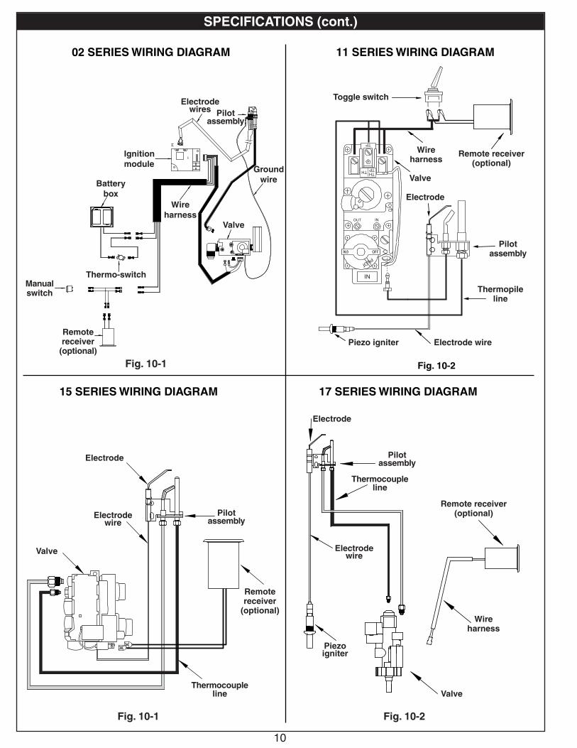
S
02 SERIES WIRING DIAGRAM
Fig. 10-1
Remote receiver(optional)
Valve
Ignition module
Wire harness
Battery box
Ground wire
Pilot assembly
Electrode wires
Fig. 10-2
11 SERIES WIRING DIAGRAM
Toggle switch
Wire harness
Valve
Pilot assembly
Thermopile line
Manual switch
Electrode wirePiezo igniter
Electrode
15 SERIES WIRING DIAGRAM
Fig. 10-1 Fig. 10-2
17 SERIES WIRING DIAGRAM
Valve
Thermocouple line
Pilot assembly
Remote receiver(optional)
Wire harness
Electrode wire
Piezo igniter
Electrode
Valve
Thermocouple line
Pilot assembly
Remote receiver
(optional)
Electrode wire
Electrode
Remote receiver
(optional)
Thermo-switch

11
Damper clamp
Set screw
Open Closed
DAMPER CLAMP INSTRUCTIONS
Fig. 11-1 Damper clamp detail
Fig. 11-2 Damper open / closed
The damper clamp with hex bolt (Fig. 11-1) is provided as a means to prevent full closure of the damper blade. The clamp is easily attached to most damper blades with pliers or a wrench, and must be permanently installed. The clamp is designed to prevent accidental closure of the damper when installed as illustrated (Fig. 11-2). Should the clamp not fit, or fail to provide the permanent vent opening listed in Table 3 below, have a permanent stop installed, remove the damper blade, or have the damper cut to provide the minimum permanent opening required.
Minimum permanent free opening area of chimney damper for venting (sq. in.)
For factory-built fireplaces
Chimney height 18/20" 24" 30"
15' 18 24 30
20' 15 21 25
30' 12 16 19
For masonry-built fireplaces
15' 27 35 41
20' 24 32 38
30' 22 29 34
Table 3 - Minimum Chimney Damper Vent Opening Requirements
THE DAMPER MUST BE COMPLETELY OPENED WHEN OPERATING THIS GAS APPLIANCE TO ACHIEVE THE BEST VENTILATION POSSIBLE.
THESE ARE MINIMUM DAMPER OPENING SPECIFICATIONS.
Note: The minimum chimney height from hearth to top of chimney is 15'.
Venting Requirements
12
G46 BURNER PARTS LIST - MANUAL PILOT SERIES
Note: Photos not to scale
Replacement parts can be ordered from your local Real Fyre dealer.
24" burner model shown
Rear view12
Pilot
7
3
18/20" model 24" model 30" modelItem Description Part No. Qty. Part No. Qty. Part No. Qty.
1.or
Pilot assembly (natural)Pilot assembly (propane)
PT-1NATPT-1LP
11
PT-1NATPT-1LP
11
PT-1NATPT-1LP
11
2. Electrode CE-15 1 CE-15 1 CE-15 1
3. Control valve (natural or propane models) SV-19 1 SV-19 1 SV-19 1
4.or
Pressure regulator (natural)Pressure regulator (propane)
PR-1NATPR-1LP
11
PR-1NATPR-1LP
11
PR-1NATPR-1LP
11
5. Flex connector (w/ adapter), 1/2" O.D. x 24" CK-5-24 1 CK-5-24 1 CK-5-24 1
6. Piezo igniter PZ-1 1 PZ-1 1 PZ-1 1
7. Control knob w/extension EH-13 1 EH-13 1 EH-13 1
8. Grate SD-18 1 SD-24 1 SD-30 1
9. Log locator (w/ screw and nut) UP-17 2 UP-17 2 UP-17 2
10.or
Sand (natural gas)Vermiculite (propane gas)
CS-6LF-15-3.5
11
CS-8LF-15-7
11
CS-10LF-15
11
11. Glowing embers EM-1 1 EM-1 1 EM-1 1
12. Damper clamp DC-1 1 DC-1 1 DC-1 1
4
Thermocouple
8
1
6
The log set is purchased and packaged separately; contact your local Real Fyre dealer when ordering. Refer to the instructions included with the log set.
5
9
10
11
Electrode
2

13
G46 BURNER PARTS LIST - 02 SERIES
18/20" model 24" model 30" modelItem Description Part No. Qty. Part No. Qty. Part No. Qty.
1.or
Pilot assembly (natural)Pilot assembly (propane)
PAC-11PAC-11P
11
PAC-11PAC-11P
11
PAC-11PAC-11P
11
2.or
Control valve (natural)Control valve (propane)
SV-45SV-45P
11
SV-45SV-45P
11
SV-45SV-45P
11
3. Switch box assembly (includes battery box, module, ON/OFF switch, thermo switch, metal heat shield) EPK-64A 1 EPK-64A 1 EPK-64A 1
4. Main harness assembly WH-12 1 WH-12 1 WH-12 1
5. Control module IMP-1 1 IMP-1 1 IMP-1 1
6. Battery pack IMP-2 1 IMP-2 1 IMP-2 1
7. Remote kit * † (includes receiver, transmitter, batteries, plastic cover) RR-1A 1 RR-1A 1 RR-1A 1
8. Remote transmitter (only) * AT-R1-1 1 AT-R1-1 1 AT-R1-1 1
9. Decorative heat shield (remote) * † HS-36 1 HS-36 1 HS-36 1
10. Decorative heat shield (valve) HS-38A 1 HS-38A 1 HS-38A 1
11. Remote receiver wire harness * † WH-10 1 WH-10 1 WH-10 1
12. Flex connector (w/ adapter), 1/2" O.D. x 24" CK-5-SP 1 CK-5-SP 1 CK-5-SP 1
13. Grate S4-18 1 S4-24 1 S4-30 1
14. Log locator (w/ screw and nut) UP-17 2 UP-17 2 UP-17 2
15.or
Sand (natural gas)Vermiculite (propane gas)
CS-6LF-15-3.5
11
CS-8LF-15-7
11
CS-10LF-15
11
16. Glowing embers EM-1 1 EM-1 1 EM-1 1
17. Damper clamp DC-1 1 DC-1 1 DC-1 1
* if equipped† to add a remote system to an 02M model, use RR-1A, HS-36, and WH-10
1
Electrode
Heat sensor
Note: Photos not to scale
Replacement parts can be ordered from your local Real Fyre dealer.
24" burner model shown
17
13
12
14
15
16
10
Bottom view2
The log set is purchased and packaged separately; contact your Real Fyre dealer when ordering. Refer to instructions included with log set.
3
6
5
7
8
9 Remote transmitter and system batteries included with burner system (as applicable).
Pilot
11
Important: Minimum fireplace size for 02 series is larger than other G46 models (by 6" front & 4" rear width).
4

14
G46 BURNER PARTS LIST - 11 SERIES
18/20" model 24" model 30" modelItem Description Part No. Qty. Part No. Qty. Part No. Qty.
1.or
Pilot assembly (natural)Pilot assembly (propane)
PG-1-12NATPG-1-12LP
11
PG-1-12NATPG-1-12LP
11
PG-1-12NATPG-1-12LP
11
2. Electrode CE-15 1 CE-15 1 CE-15 1
3.or
Control valve (natural)Control valve (propane)
SV-6SV-6P
11
SV-6SV-6P
11
SV-6SV-6P
11
4. Remote kit * †(includes receiver, transmitter, batteries, plastic cover)
RR-1A 1 RR-1A 1 RR-1A 1
5. Remote transmitter (only) * AT-R1-1 1 AT-R1-1 1 AT-R1-1 1
6. Decorative heat shield * † HS-36 1 HS-36 1 HS-36 1
7. Flex connector (w/ adapter), 1/2" O.D. x 24" CK-5-SP 1 CK-5-SP 1 CK-5-SP 1
8. Piezo igniter PZ-1 1 PZ-1 1 PZ-1 1
9. Toggle switch SW-2 1 SW-2 1 SW-2 1
10. Grate S4-18 1 S4-24 1 S4-30 1
11. Log locator (w/ screw and nut) UP-17 2 UP-17 2 UP-17 2
12.or
Sand (natural gas)Vermiculite (propane gas)
CS-6LF-15-3.5
11
CS-8LF-15-7
11
CS-10LF-15
11
13. Glowing embers EM-1 1 EM-1 1 EM-1 1
14. Damper clamp DC-1 1 DC-1 1 DC-1 1
* if equipped† to add a remote system to an 11M model, use RR-1A and HS-36
Note: Photos not to scale
Replacement parts can be ordered from your local Real Fyre dealer.
24" burner model shown
Side view14
9
3
10
8
7
11
12
13
Pilot
Thermopile
Electrode
6
4
5
The log set is purchased and packaged separately; contact your local Real Fyre dealer when ordering. Refer to the instructions included with the log set.
12
15
G46 BURNER PARTS LIST - 15 SERIES
18/20" model 24" model 30" modelItem Description Part No. Qty. Part No. Qty. Part No. Qty.
1.or
Pilot assembly (natural)Pilot assembly (propane)
PT-1NATPT-1LP
11
PT-1NATPT-1LP
11
PT-1NATPT-1LP
11
2. Electrode CE-15 1 CE-15 1 CE-15 1
3.or
Control valve (natural)Control valve (propane)
SV-22SV-23
11
SV-22SV-23
11
SV-22SV-23
11
4.or
Pressure regulator (natural)Pressure regulator (propane)
PR-3NATPR-2LP
11
PR-3NATPR-2LP
11
PR-3NATPR-2LP
11
5. Remote kit * †(includes receiver, transmitter, batteries, plastic cover)
VR-1A 1 VR-1A 1 VR-1A 1
6. Remote transmitter (only) * AT-V1-1 1 AT-V1-1 1 AT-V1-1 1
7. Decorative heat shield * † HS-36 1 HS-36 1 HS-36 1
8. Flex connector (w/ adapter), 1/2" O.D. x 24" CK-5-24 1 CK-5-24 1 CK-5-24 1
9. Grate S4-18 1 S4-24 1 S4-30 1
10. Log locator (w/ screw and nut) UP-17 2 UP-17 2 UP-17 2
11.or
Sand (natural gas)Vermiculite (propane gas)
CS-6LF-15-3.5
11
CS-8LF-15-7
11
CS-10LF-15
11
12. Glowing embers EM-1 1 EM-1 1 EM-1 1
13. Damper clamp DC-1 1 DC-1 1 DC-1 1
* if equipped† to add a remote system to a 15M model, use VR-1A and HS-36
Note: Photos not to scale
Replacement parts can be ordered from your local Real Fyre dealer.
24" burner model shown
Side view13
3
4
9
8
10
11
12
Pilot
ThermocoupleElectrode
5
6
7
The log set is purchased and packaged separately; contact your local Real Fyre dealer when ordering. Refer to the instructions included with the log set.
1
2

16
G46 BURNER PARTS LIST - 17 SERIES
18/20" model 24" model 30" modelItem Description Part No. Qty. Part No. Qty. Part No. Qty.
1.or
Pilot assembly (natural)Pilot assembly (propane)
PT-1NATPT-1LP
11
PT-1NATPT-1LP
11
PT-1NATPT-1LP
11
2. Electrode CE-15 1 CE-15 1 CE-15 1
3. Control valve (natural or propane models) SV-37 1 SV-37 1 SV-37 1
4.or
Pressure regulator (natural)Pressure regulator (propane)
PR-1NATPR-1LP
11
PR-1NATPR-1LP
11
PR-1NATPR-1LP
11
5. Remote kit * †(includes receiver, transmitter, batteries, plastic cover)
VR-1A 1 VR-1A 1 VR-1A 1
6. Remote transmitter (only) * AT-V1-1 1 AT-V1-1 1 AT-V1-1 1
7. Decorative heat shield * † HS-36 1 HS-36 1 HS-36 1
8. Remote receiver wire harness * † WH-01 1 WH-01 1 WH-01 1
9. Flex connector (w/ adapter), 1/2" O.D. x 24" CK-5-24 1 CK-5-24 1 CK-5-24 1
10. Piezo igniter PZ-1 1 PZ-1 1 PZ-1 1
11. Control knob w/extension EH-13 1 EH-13 1 EH-13 1
12. Grate SD-18 1 SD-24 1 SD-30 1
13. Log locator (w/ screw and nut) UP-17 2 UP-17 2 UP-17 2
14.or
Sand (natural gas)Vermiculite (propane gas)
CS-6LF-15-3.5
11
CS-8LF-15-7
11
CS-10LF-15
11
15. Glowing embers EM-1 1 EM-1 1 EM-1 1
16. Damper clamp DC-1 1 DC-1 1 DC-1 1
* if equipped† to add a remote system to a 17M model, use VR-1A, HS-36, and WH-01
24" burner model shown
16
11
Rear view3 4
12
10
9
13
14
15
5
67
Pilot
ThermocoupleElectrode
1
2
8
Note: Photos not to scale
Replacement parts can be ordered from your local Real Fyre dealer.
The log set is purchased and packaged separately; contact your Real Fyre dealer when ordering. Refer to instructions included with log set.
17
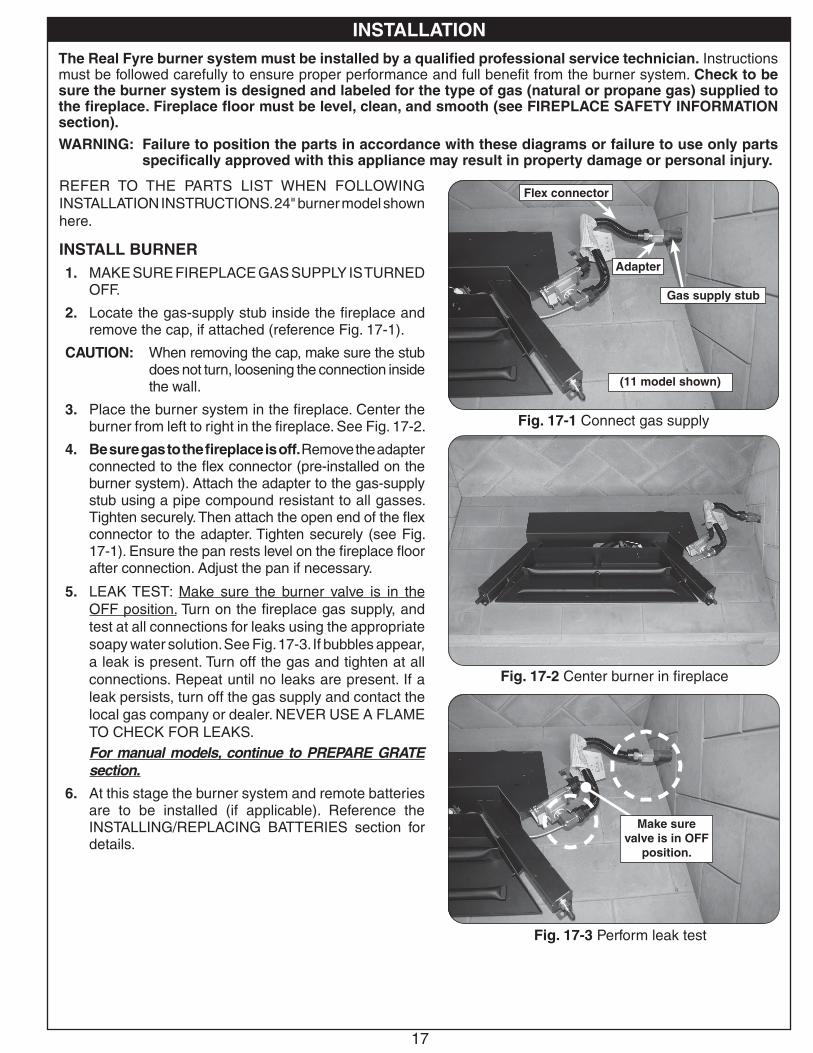
REFER TO THE PARTS LIST WHEN FOLLOWING INSTALLATION INSTRUCTIONS. 24" burner model shown here.
INSTALL BURNER1. MAKE SURE FIREPLACE GAS SUPPLY IS TURNED
OFF.
2. Locate the gas-supply stub inside the fireplace and remove the cap, if attached (reference Fig. 17-1).
CAUTION: When removing the cap, make sure the stub does not turn, loosening the connection inside the wall.
3. Place the burner system in the fireplace. Center the burner from left to right in the fireplace. See Fig. 17-2.
4. Be sure gas to the fireplace is off. Remove the adapter connected to the flex connector (pre-installed on the burner system). Attach the adapter to the gas-supply stub using a pipe compound resistant to all gasses. Tighten securely. Then attach the open end of the flex connector to the adapter. Tighten securely (see Fig. 17-1). Ensure the pan rests level on the fireplace floor after connection. Adjust the pan if necessary.
5. LEAK TEST: Make sure the burner valve is in the OFF position. Turn on the fireplace gas supply, and test at all connections for leaks using the appropriate soapy water solution. See Fig. 17-3. If bubbles appear, a leak is present. Turn off the gas and tighten at all connections. Repeat until no leaks are present. If a leak persists, turn off the gas supply and contact the local gas company or dealer. NEVER USE A FLAME TO CHECK FOR LEAKS.For manual models, continue to PREPARE GRATE section.
6. At this stage the burner system and remote batteries are to be installed (if applicable). Reference the INSTALLING/REPLACING BATTERIES section for details.
The Real Fyre burner system must be installed by a qualified professional service technician. Instructions must be followed carefully to ensure proper performance and full benefit from the burner system. Check to be sure the burner system is designed and labeled for the type of gas (natural or propane gas) supplied to the fireplace. Fireplace floor must be level, clean, and smooth (see FIREPLACE SAFETY INFORMATION section).
WARNING: Failure to position the parts in accordance with these diagrams or failure to use only parts specifically approved with this appliance may result in property damage or personal injury.
INSTALLATION
Fig. 17-2 Center burner in fireplace
Fig. 17-1 Connect gas supply
Flex connector
Adapter
Gas supply stub
(11 model shown)
Fig. 17-3 Perform leak test
Make sure valve is in OFF
position.
INSTALLATION
18
INSTALLATION (cont.)
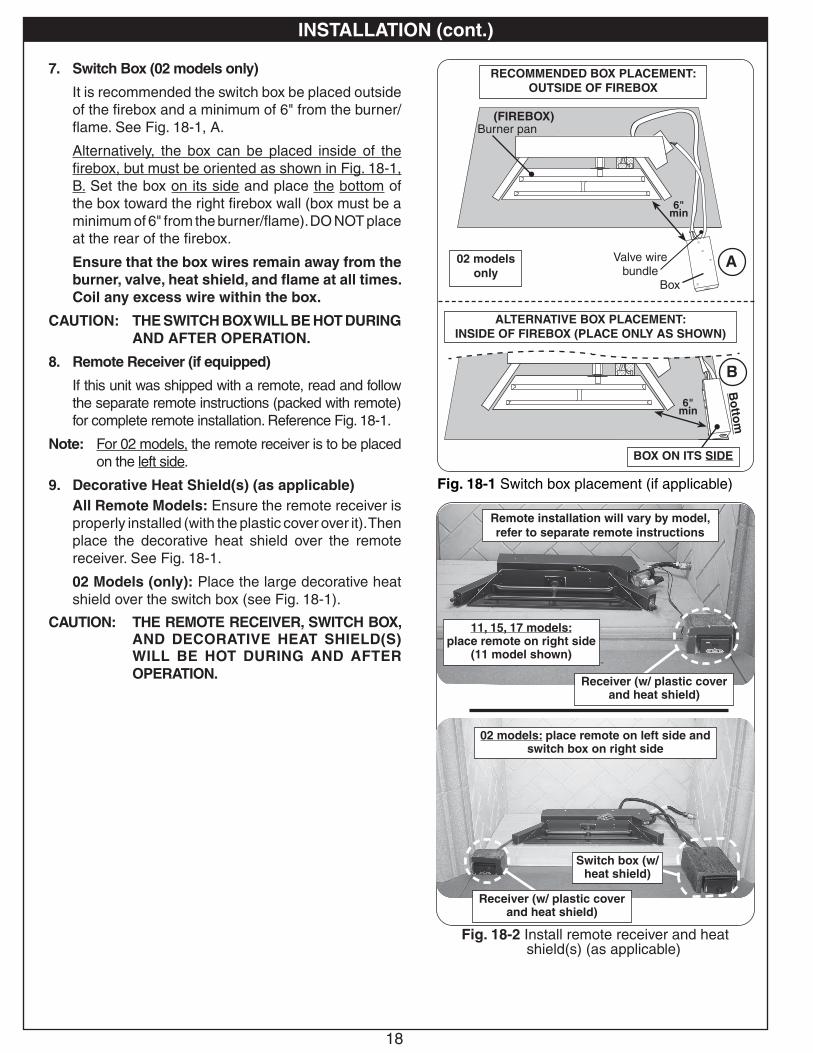
7. Switch Box (02 models only)
It is recommended the switch box be placed outside of the firebox and a minimum of 6" from the burner/flame. See Fig. 18-1, A.
Alternatively, the box can be placed inside of the firebox, but must be oriented as shown in Fig. 18-1, B. Set the box on its side and place the bottom of the box toward the right firebox wall (box must be a minimum of 6" from the burner/flame). DO NOT place at the rear of the firebox.
Ensure that the box wires remain away from the burner, valve, heat shield, and flame at all times. Coil any excess wire within the box.
CAUTION: THE SWITCH BOX WILL BE HOT DURING AND AFTER OPERATION.
8. Remote Receiver (if equipped)
If this unit was shipped with a remote, read and follow the separate remote instructions (packed with remote) for complete remote installation. Reference Fig. 18-1.
Note: For 02 models, the remote receiver is to be placed on the left side.
9. Decorative Heat Shield(s) (as applicable)All Remote Models: Ensure the remote receiver is properly installed (with the plastic cover over it). Then place the decorative heat shield over the remote receiver. See Fig. 18-1.
02 Models (only): Place the large decorative heat shield over the switch box (see Fig. 18-1).
CAUTION: THE REMOTE RECEIVER, SWITCH BOX, AND DECORATIVE HEAT SHIELD(S) WILL BE HOT DURING AND AFTER OPERATION.
Fig. 18-2 Install remote receiver and heat shield(s) (as applicable)
Remote installation will vary by model, refer to separate remote instructions
11, 15, 17 models:place remote on right side
(11 model shown)
Receiver (w/ plastic cover and heat shield)
02 models: place remote on left side and switch box on right side
Receiver (w/ plastic cover and heat shield)
Switch box (w/ heat shield)
Fig. 18-1 Switch box placement (if applicable)
RECOMMENDED BOX PLACEMENT:OUTSIDE OF FIREBOX
ALTERNATIVE BOX PLACEMENT:INSIDE OF FIREBOX (PLACE ONLY AS SHOWN)
Valve wire bundle
Box
Burner pan
6"min
(FIREBOX)
02 models only
A
Bo
ttom
6"min
B
BOX ON ITS SIDE
19
Fig. 19-1 Attach log locators to grate
Fig. 19-2 Log locators attached to grate
Fig. 19-3 Position grate
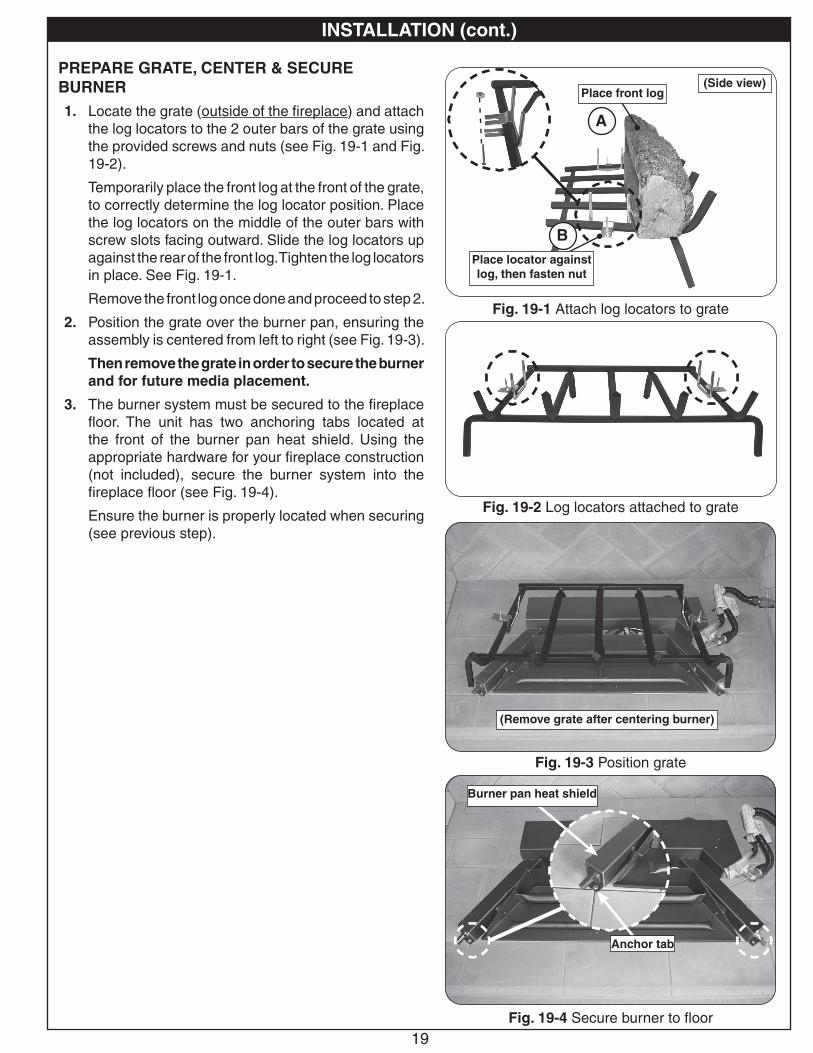
PREPARE GRATE, CENTER & SECURE BURNER1. Locate the grate (outside of the fireplace) and attach
the log locators to the 2 outer bars of the grate using the provided screws and nuts (see Fig. 19-1 and Fig. 19-2).
Temporarily place the front log at the front of the grate, to correctly determine the log locator position. Place the log locators on the middle of the outer bars with screw slots facing outward. Slide the log locators up against the rear of the front log. Tighten the log locators in place. See Fig. 19-1.
Remove the front log once done and proceed to step 2.
2. Position the grate over the burner pan, ensuring the assembly is centered from left to right (see Fig. 19-3).
Then remove the grate in order to secure the burner and for future media placement.
3. The burner system must be secured to the fireplace floor. The unit has two anchoring tabs located at the front of the burner pan heat shield. Using the appropriate hardware for your fireplace construction (not included), secure the burner system into the fireplace floor (see Fig. 19-4).
Ensure the burner is properly located when securing (see previous step).
INSTALLATION (cont.)
Fig. 19-4 Secure burner to floor
Anchor tab
Burner pan heat shield
A
B
(Side view)Place front log
Place locator against log, then fasten nut
(Remove grate after centering burner)

20
LIGHTING TESTPrior to proceeding with installation, perform a lighting test (see lighting instructions for lighting your burner). Allow the unit to completely cool after testing.
LAVA GRANULES/COALS (optional)Optional lava granules and lava coals are available for decorative purposes. Contact your dealer for ordering information.If purchased, follow the steps below.
1. Spread the lava granules on the floor of the fireplace, around the front and sides of the burner system (see Fig. 20-1).
2. Repeat this process for the lava coals (on top of the already placed lava granules).
Note: DO NOT place any lava media on the burner system, behind it, or under a knob/igniter/switch if one exists at the ends of the burner (see Fig. 20-2).
If applicable, the lava media may be placed around the receiver/switch box. Leave the front of the receiver/switch box clear for control access.
SAND/VERMICULITE PLACEMENTThe sand/vermiculite supplied with the unit is specially selected for use with either natural or propane gas. It maximizes flame distribution and provides a cleaner burning flame.
CAUTION: Use only sand for natural gas burners and vermiculite for propane gas burners.
1. Fill the burner pan completely with the sand/vermiculite (see Fig. 20-3). Avoid spilling the sand/vermiculite on the pilot assembly. DO NOT place sand/vermiculite on any other parts of the burner / heat shield.
2. Slope the sand/vermiculite at the same angle as the burner pan. This is important to ensure quiet lighting and even flame distribution. See Fig. 20-4.
INSTALLATION (cont.)
Fig. 20-1 Place lava media (if option purchased)
Fig. 20-3 Place sand/vermiculite
Fig. 20-4 Sand/vermiculite detail
Fill pan (only) with sand /
vermiculite & slope with pan.
Fig. 20-2 Proper lava media placement
Keep clear (both ends)
(11 model shown)
IMPORTANT
For all valves, the air MUST be purged from the gas line before the pilot will light and burn properly. The time needed to purge will depend on the length of the gas line to the unit and the amount of time since the unit or gas line was last used. It may take several minutes before all the air is purged and the pilot will light and burn properly. Reference the LIGHTING INSTRUCTIONS section in this manual.

21
GLOWING EMBERS PLACEMENTSprinkle the glowing embers lightly and evenly over the entire surface of the sand/vermiculite as shown in Fig. 21-1. Break up any clumps that may have developed during shipment. Store unused embers for later use/replacement.
GRATE PLACEMENTCenter the grate over the burner pan (see Fig. 21-3).
KEEP LAVA GRANULES/COALS, SAND/VERMICULITE, EMBERS, AND ALL FOREIGN OBJECTS AWAY FROM THE PILOT ASSEMBLY, VALVE ASSEMBLY, AND HEAT SHIELD(S) DURING MEDIA PLACEMENT AND AT ALL TIMES. SEE FIG. 21-2 FOR PILOT DETAIL.
INSTALLATION (cont.)
Fig. 21-1 Place glowing embers
Fig. 21-2 Keep pilot clear
KEEP CLEAR OF ALL MEDIA
(11 model shown)
Place embers as shown
Fig. 21-3 Place grate
22
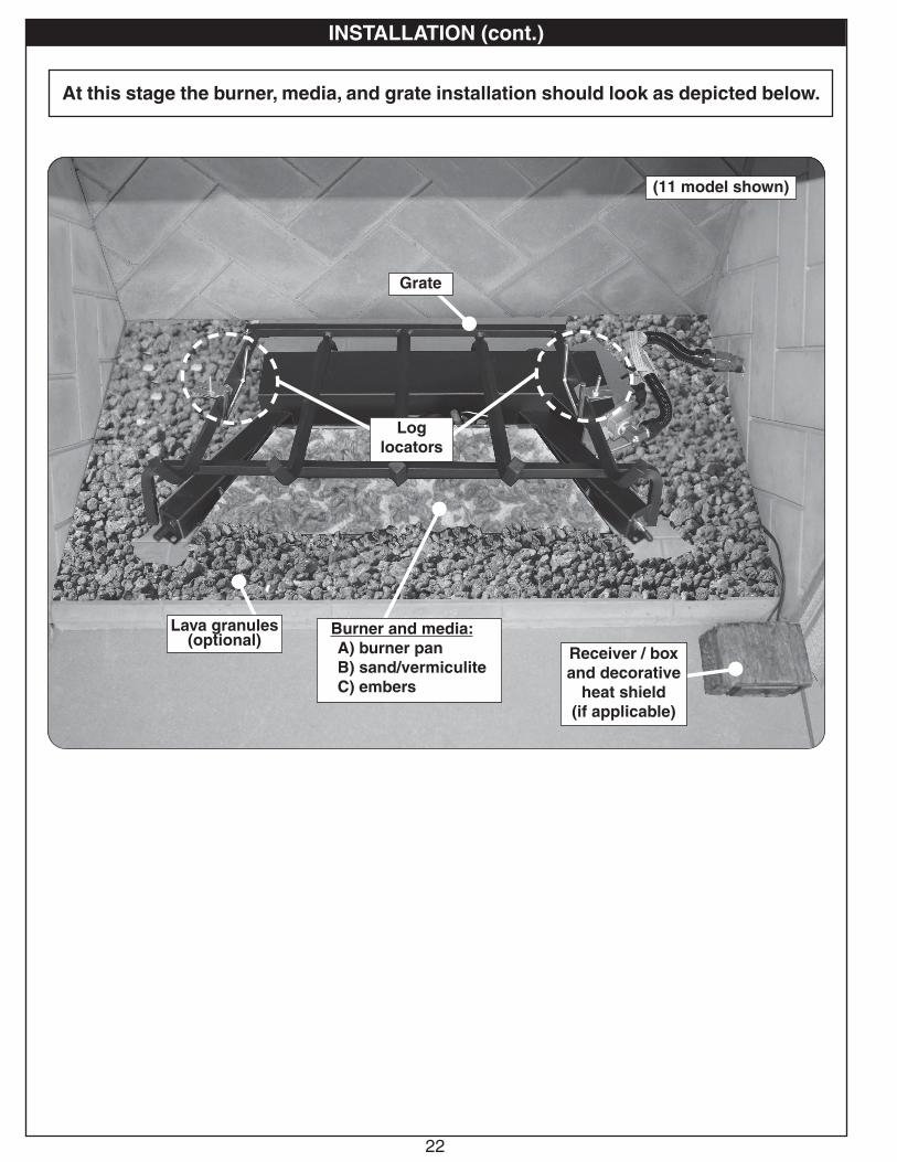
INSTALLATION (cont.)
At this stage the burner, media, and grate installation should look as depicted below.
(11 model shown)
Log locators
Burner and media:A) burner panB) sand/vermiculiteC) embers
Lava granules (optional)
Grate
Receiver / box and decorative
heat shield(if applicable)
23
INSTALLATION (cont.)
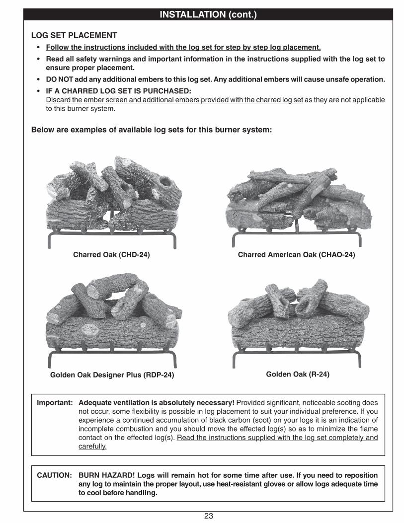
CAUTION: BURN HAZARD! Logs will remain hot for some time after use. If you need to reposition any log to maintain the proper layout, use heat-resistant gloves or allow logs adequate time to cool before handling.
LOG SET PLACEMENT• Follow the instructions included with the log set for step by step log placement.
• Read all safety warnings and important information in the instructions supplied with the log set to ensure proper placement.
• DO NOT add any additional embers to this log set. Any additional embers will cause unsafe operation.
• IF A CHARRED LOG SET IS PURCHASED:Discard the ember screen and additional embers provided with the charred log set as they are not applicable to this burner system.
Below are examples of available log sets for this burner system:
Important: Adequate ventilation is absolutely necessary! Provided significant, noticeable sooting does not occur, some flexibility is possible in log placement to suit your individual preference. If you experience a continued accumulation of black carbon (soot) on your logs it is an indication of incomplete combustion and you should move the effected log(s) so as to minimize the flame contact on the effected log(s). Read the instructions supplied with the log set completely and carefully.
Charred Oak (CHD-24)
Golden Oak Designer Plus (RDP-24)
Charred American Oak (CHAO-24)
Golden Oak (R-24)
24
INSTALLING/REPLACING BATTERIES (IF APPLICABLE)
CAUTION: Ensure the unit is connected to the gas line and has been tested for leaks before you insert batteries.
CAUTION: Turn off the remote and/or burner and allow the unit to completely cool prior to any battery replacements.
Important: Prior to inserting batteries, always apply a small amount of dielectric grease to both ends of each battery. This will ensure conductivity and prevent moisture from affecting the contact.
Important: Low/dead batteries will affect burner system operation. Replace batteries any time the burner will not turn on.
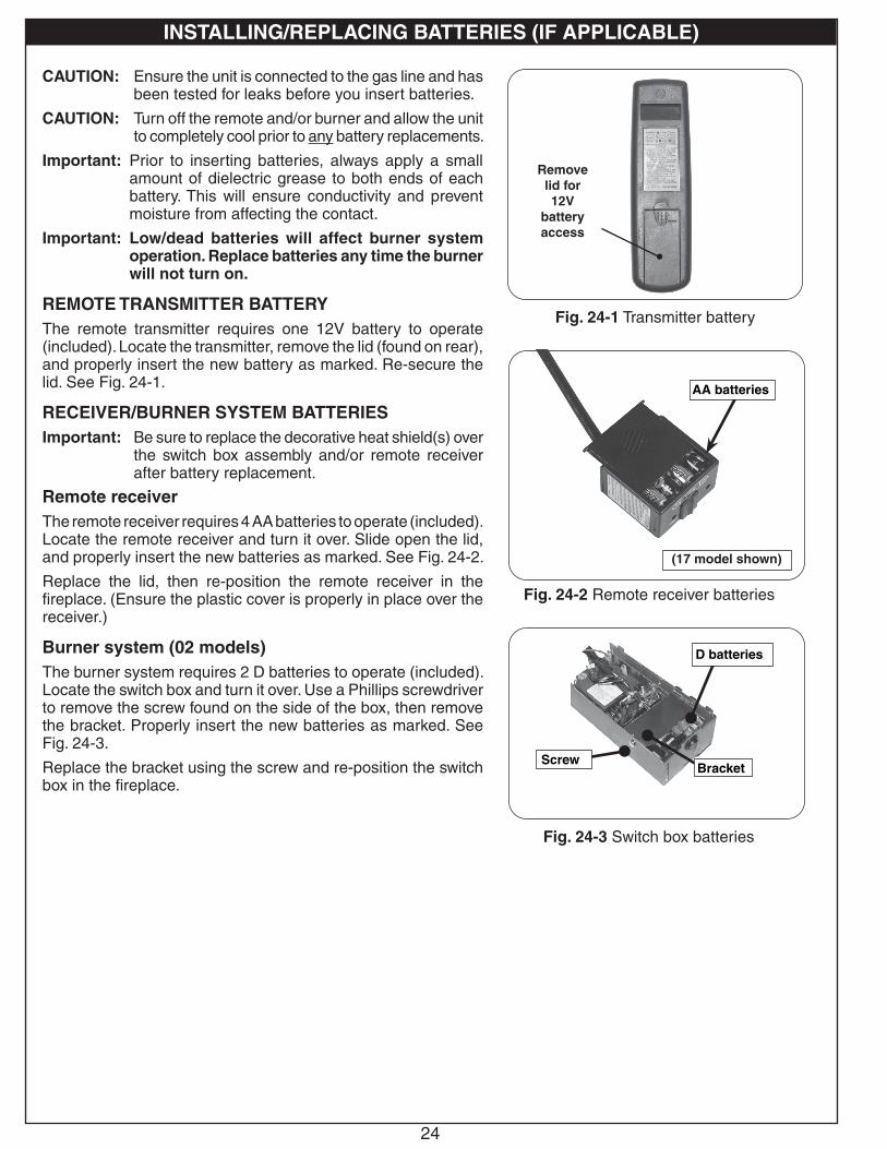
REMOTE TRANSMITTER BATTERYThe remote transmitter requires one 12V battery to operate (included). Locate the transmitter, remove the lid (found on rear), and properly insert the new battery as marked. Re-secure the lid. See Fig. 24-1.
RECEIVER/BURNER SYSTEM BATTERIESImportant: Be sure to replace the decorative heat shield(s) over
the switch box assembly and/or remote receiver after battery replacement.
Remote receiverThe remote receiver requires 4 AA batteries to operate (included). Locate the remote receiver and turn it over. Slide open the lid, and properly insert the new batteries as marked. See Fig. 24-2.
Replace the lid, then re-position the remote receiver in the fireplace. (Ensure the plastic cover is properly in place over the receiver.)
Burner system (02 models)The burner system requires 2 D batteries to operate (included). Locate the switch box and turn it over. Use a Phillips screwdriver to remove the screw found on the side of the box, then remove the bracket. Properly insert the new batteries as marked. See Fig. 24-3.
Replace the bracket using the screw and re-position the switch box in the fireplace.
Fig. 24-1 Transmitter battery
Remove lid for 12V
battery access
AA batteries
Fig. 24-2 Remote receiver batteries
(17 model shown)
Fig. 24-3 Switch box batteries
D batteries
BracketScrew
25
����� �����
���
��� �
���
����������
��� �������
���
����
���
������
����
����
����
��
FOR YOUR SAFETY, READ BEFORE LIGHTING
WARNING: If you do not follow these instructions exactly, a fire or explosion may result causing property damage, personal injury or loss of life.
A. Use only your hand to push in or turn the gas control knob. Never use tools. If the knob will not push in or turn by hand, don't try to repair it. Call a qualified professional service technician. Excessive force or attempted repair may result in fire or explosion.
B. BEFORE OPERATING, smell all around the appliance area for gas. Be sure to smell next to the floor because some gas is heavier than air and will settle on the floor.
WHAT TO DO IF YOU SMELL GAS
• Do not light any appliance.
• Do not touch any electric switch; do not use any phone in your building.
• Immediately call your gas supplier from a neighbor's phone. Follow the gas supplier's instructions. If you cannot reach your gas supplier, call the fire department.
C. The burner system has a pilot that can be lit using the built-in piezo igniter, or by hand using a long fireplace match or lighter. When lighting the pilot, follow these instructions exactly.
D. Do not use this appliance if any part has been underwater. Immediately call a qualified service technician to inspect the appliance and to replace any part of the control system and any gas control which has been underwater. Attempted operation may result in fire or explosion resulting in property damage, personal injury or loss of life.
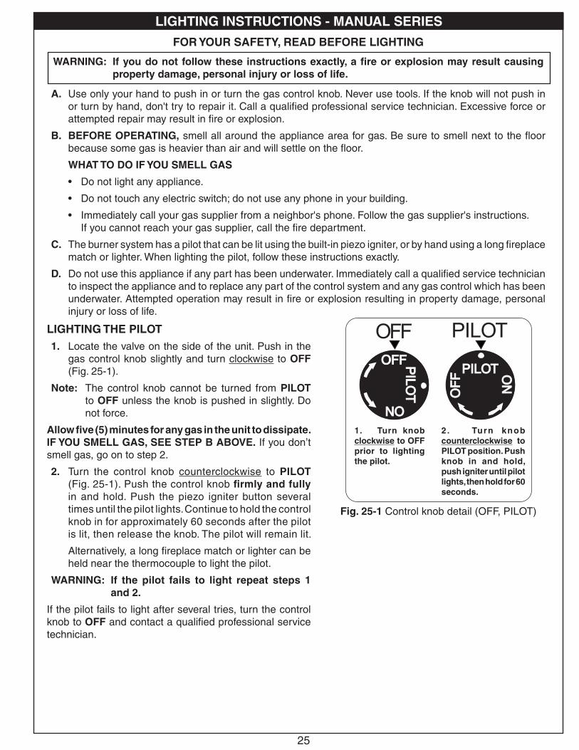
LIGHTING THE PILOT1. Locate the valve on the side of the unit. Push in the
gas control knob slightly and turn clockwise to OFF (Fig. 25-1).
Note: The control knob cannot be turned from PILOT to OFF unless the knob is pushed in slightly. Do not force.
Allow five (5) minutes for any gas in the unit to dissipate. IF YOU SMELL GAS, SEE STEP B ABOVE. If you don’t smell gas, go on to step 2.
2. Turn the control knob counterclockwise to PILOT (Fig. 25-1). Push the control knob firmly and fully in and hold. Push the piezo igniter button several times until the pilot lights. Continue to hold the control knob in for approximately 60 seconds after the pilot is lit, then release the knob. The pilot will remain lit.
Alternatively, a long fireplace match or lighter can be held near the thermocouple to light the pilot.
WARNING: If the pilot fails to light repeat steps 1 and 2.
If the pilot fails to light after several tries, turn the control knob to OFF and contact a qualified professional service technician.
Fig. 25-1 Control knob detail (OFF, PILOT)
1. Turn knob clockwise to OFF prior to lighting the pilot.
LIGHTING INSTRUCTIONS - MANUAL SERIES
2. Turn knob counterclockwise to PILOT position. Push knob in and hold, push igniter until pilot lights, then hold for 60 seconds.
USE, CARE, & SERVICE

26
POUR VOTRE SÉCURITÉ, LISEZ AVANT D'ALLUMER
AVERTISSEMENT: Si vous ne suivez pas ces instructions à la lettre, un incendie ou une explosion entraînant des dommages matériels, des blessures ou des pertes de vie.
A. N'utilisez que votre main pour enfoncer ou tourner le bouton de contrôle du gaz. Ne jamais utiliser d'outils. Si le bouton ne sera pas enfoncer ou à tourner à la main, n'essayez pas de le réparer. Appelez un technicien de service qualifié. Une force excessive ou une tentative de réparation pourrait provoquer un incendie ou une explosion.
B. AVANT DE FAIRE FONCTIONNER, sentez autour de l'appareil pour le gaz. Assurez-vous de sentir près du plancher, car certains gaz sont plus lourds que l'air et se déposent sur le sol.
QUE FAIRE SI UNE ODEUR DE GAZ
• Ne pas allumer l'appareil.
• Ne touchez à aucun interrupteur électrique; n'utilisez aucun téléphone dans votre bâtiment.
• Appelez immédiatement votre fournisseur de gaz à partir du téléphone d'un voisin. Suivez les instructions du fournisseur de gaz. Si vous ne pouvez joindre votre fournisseur de gaz, appeler les pompiers.
C. Le système de brûleur a un pilote qui peut être allumée usar el encendedor piezoeléctrico incorporado, oro à la main à l'aide d'une allumette ou long cou léger. Pour allumer la veilleuse, suivez ces instructions à la lettre.
D. Ne pas utiliser cet appareil si une partie quelconque a été submergée. Appelez immédiatement un technicien de service qualifié pour inspecter l'appareil et pour remplacer toute pièce du système de contrôle et toute commande de gaz qui a été sous l'eau. Tentative d'opération peut entraîner un incendie ou une explosion entraînant des dommages matériels, des blessures ou des pertes de vie.
����� �����
���
��� �
���
����������
��� ���
����
���
����
���
������
����
����
����
��
Fig. 26-1 Détail bouton de commande(OFF, PILOTE)
1. Tourner le bouton dans le sens horaire en position OFF avant d'allumer la veilleuse.
OFF PILOTEALLUMAGE DU PILOTE1. Localiser la vanne sur le côté de l'appareil. Appuyer
sur le bouton légèrement de contrôle du gaz et tourner dans le sens horaire à OFF (Fig. 26-1).
Note: Le bouton de commande ne peut être activée à partir PILOTE sur OFF si le bouton est enfoncé légèrement. Ne pas forcer.
Attendez cinq (5) minutes pour n'importe quel gaz dans l'unité de se dissiper. S'IL YA UNE ODEUR DE GAZ, voir l'étape B CI-DESSUS. Si vous ne sentez pas de gaz, passez à l'étape 2.
2. Tournez le bouton de réglage dans le sens antihoraire pour PILOTE (Fig. 26-1). Appuyez sur le bouton de commande fermement et pleinement enfoncée. Empuje el botón del encendedor piezoeléctrico Varias veces hasta las luces piloto. Continuez à tenir le bouton de commande pendant environ 60 secondes après que le pilote est allumé, puis relâchez le bouton. Le pilote reste allumé.
Alternativamente, un partido largo chimenea o más claro puede ser considerado cerca del termopar a encender el piloto.
AVERTISSEMENT: Si le pilote ne s'allume pas, répétez les étapes 1 et 2.
Si la télécommande ne fonctionne pas, et des batteries avec un niveau de puissance adéquate sont installés, reportez-vous à la synchronisation des section REMOTE.
INSTRUCTIONS D'ALLUMAGE - SÉRIE MANUEL
2. Gire la perilla en sentido antihorario hasta la posición PILOTO. Empujando al botón y mantenga, empuje encendedor hasta las luces piloto, A cont inuac ión , mantenga durante 60 segundos.

27
LIGHTING THE BURNER1. Ensure the pilot is burning. Turn the gas control knob
counterclockwise to ON (Fig. 27-1) to ignite the burner. The valve will open and the burner will light.
Note: The ignition sequence will take approximately 5 seconds.
WARNING: If the burner fails to light within 5 seconds, turn the control knob clockwise to PILOT. Allow five (5) minutes for any gas in the unit to dissipate, then repeat step 1 above. IF YOU SMELL GAS, SEE STEP B AT BEGINNING OF LIGHTING INSTRUCTIONS.
If the burner fails to light after several tries, push in the control knob slightly and turn clockwise to OFF, and contact a qualified professional service technician.
SHUTTING DOWNMAIN BURNER ONLY (pilot will remain lit):
Turn the control knob clockwise to PILOT.
BURNER AND PILOT (total shutdown):
If you do not plan on using your burner system for an extended period (4 days or more), you may extinguish the pilot. This will conserve energy and save you money.
Push in the control knob slightly and turn clockwise to OFF.
PILOT BURNER CHECK/ADJUSTMENTWith the pilot burner lit and the control knob in the pilot position, check the pilot system for proper flame size and appearance (see Fig. 27-2). The pilot adjustment screw is located on the front of the gas valve (see Fig. 27-2). Using a small flat head screwdriver, adjust the pilot screw to properly size the flames. Turning the screw clockwise will lower the flames, and turning it counterclockwise will raise them. Be careful not to back the screw out of its threads.
The pilot flame should be a quiet, soft blue flame with yellow tipping that encircles the thermocouple tip.
����� �����
���
��� �
���
����������
��� ���
����
���
����
���
������
����
����
����
��
Fig. 27-1 Control knob detail (ON)
For Manual Lighting, turn knob
counterclockwise to ON position.
Fig. 27-2 Pilot adjustment detail
Pilot adjustment screw
Thermocouple
PILOT VALVE
LIGHTING INSTRUCTIONS - MANUAL SERIES (cont.)
28
����� �����
���
��� �
���
����������
��� ���
����
���
����
���
������
����
����
����
��
Fig. 28-1 Détail bouton de commande (SUR)
Pour l'éclairage manuel, tournez
le bouton dans le sens antihoraire à la
position ON.
SUR
Fig. 28-2 Détail réglage de la veilleuse
Vis de réglage de
PILOTE VANNE
Thermocouple
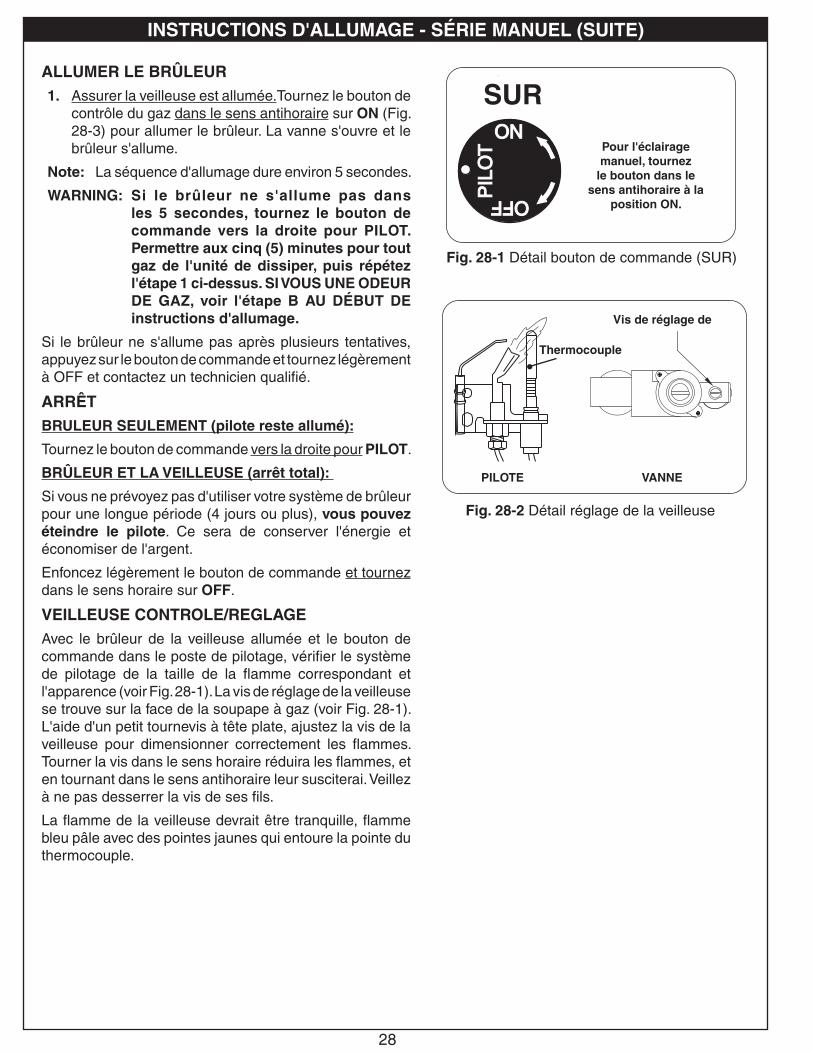
ALLUMER LE BRÛLEUR1. Assurer la veilleuse est allumée.Tournez le bouton de
contrôle du gaz dans le sens antihoraire sur ON (Fig. 28-3) pour allumer le brûleur. La vanne s'ouvre et le brûleur s'allume.
Note: La séquence d'allumage dure environ 5 secondes.
WARNING: Si le brûleur ne s'allume pas dans les 5 secondes, tournez le bouton de commande vers la droite pour PILOT. Permettre aux cinq (5) minutes pour tout gaz de l'unité de dissiper, puis répétez l'étape 1 ci-dessus. SI VOUS UNE ODEUR DE GAZ, voir l'étape B AU DÉBUT DE instructions d'allumage.
Si le brûleur ne s'allume pas après plusieurs tentatives, appuyez sur le bouton de commande et tournez légèrement à OFF et contactez un technicien qualifié.
ARRÊTBRULEUR SEULEMENT (pilote reste allumé):
Tournez le bouton de commande vers la droite pour PILOT.
BRÛLEUR ET LA VEILLEUSE (arrêt total):
Si vous ne prévoyez pas d'utiliser votre système de brûleur pour une longue période (4 jours ou plus), vous pouvez éteindre le pilote. Ce sera de conserver l'énergie et économiser de l'argent.
Enfoncez légèrement le bouton de commande et tournez dans le sens horaire sur OFF.
VEILLEUSE CONTROLE/REGLAGEAvec le brûleur de la veilleuse allumée et le bouton de commande dans le poste de pilotage, vérifier le système de pilotage de la taille de la flamme correspondant et l'apparence (voir Fig. 28-1). La vis de réglage de la veilleuse se trouve sur la face de la soupape à gaz (voir Fig. 28-1). L'aide d'un petit tournevis à tête plate, ajustez la vis de la veilleuse pour dimensionner correctement les flammes. Tourner la vis dans le sens horaire réduira les flammes, et en tournant dans le sens antihoraire leur susciterai. Veillez à ne pas desserrer la vis de ses fils.
La flamme de la veilleuse devrait être tranquille, flamme bleu pâle avec des pointes jaunes qui entoure la pointe du thermocouple.
INSTRUCTIONS D'ALLUMAGE - SÉRIE MANUEL (SUITE)

29
FOR YOUR SAFETY, READ BEFORE LIGHTING
WARNING: If you do not follow these instructions exactly, a fire or explosion may result causing property damage, personal injury or loss of life.
A. This appliance is equipped with an ignition device that automatically lights the pilot. DO NOT attempt to light the pilot by hand.
B. BEFORE OPERATING, smell all around the appliance area for gas. Be sure to smell next to the floor because some gas is heavier than air and will settle on the floor.
WHAT TO DO IF YOU SMELL GAS
• Do not light any appliance.
• Do not touch any electric switch; do not use any phone in your building.
• Immediately call your gas supplier from a neighbor's phone. Follow the gas supplier's instructions. If you cannot reach your gas supplier, call the fire department.
C. Use only the control system (or remote if equipped) to light the pilot. This valve will not operate if the pilot is not lit and stable.
D. Do not use this appliance if any part has been under water. Immediately call a qualified service technician to inspect the appliance and to replace any part of the control system and any gas control which has been under water. Attempted operation may result in fire or explosion resulting in property damage, personal injury or loss of life.
LEARN
REMOTE ONOFF
OFF
ON
Fig. 29-2 Remote transmitter detail
ON button
OFF button
Signal light
REMOTE LIGHTING (if equipped)CAUTION: DO NOT attempt to light the pilot by hand.
Note: If the remote does not function, and batteries with an adequate power level are installed, refer to the SYNCING THE REMOTE section.
Note: Step 1 may not be required if previously done during an earlier lighting.
1. Locate the 3-position switch on the remote receiver (see Fig. 29-1), and slide the switch to the REMOTE position.
Note: Ensure that the ON/OFF switch at the front of the switch box is in the OFF (O) position.
2. Locate the remote transmitter and press the ON button (see Fig. 29-2). The ignition sequence will begin.
The remote receiver will emit an audible "beep"; then the igniter will begin to spark. After the pilot lights and is established, the valve will automatically open and the burner will light.
Note: The ignition sequence will take approximately 5 seconds.
WARNING: If the pilot fails to light within 5 seconds, or if the burner fails to light within 5 seconds of pilot lighting, press the OFF button on the remote transmitter and/or slide the switch to the OFF position. Allow five (5) minutes for any gas in the unit to dissipate, then repeat steps 1 and 2 above. IF YOU SMELL GAS, SEE STEP B ABOVE.
If the pilot fails to light after several tries, turn all control/remote system components to OFF and contact a qualified professional service technician.
Fig. 29-1 Remote receiver detail (REMOTE)
LEARN
REMOTE ONOFF
OFF
ON
LIGHTING INSTRUCTIONS - 02 SERIES

30
POUR VOTRE SÉCURITÉ LISEZ AVANT D'ALLUMER
AVERTISSEMENT: Si vous ne suivez pas ces instructions à la lettre, un incendie ou une explosion entraînant des dommages matériels, des blessures ou des pertes de vie.
A. Cet appareil est équipé d'un dispositif d'allumage qui allume automatiquement la veilleuse. NE PAS essayer d'allumer la veilleuse manuellement.
B. AVANT D'UTILISER, Sentez tout autour de l'appareil pour le gaz. Assurez-vous de sentir près du plancher, car certains gaz sont plus lourds que l'air et se déposent sur le sol.
QUE FAIRE SI UNE ODEUR DE GAZ
• Ne pas allumer l'appareil.
• Ne touchez à aucun interrupteur électrique; n'utilisez aucun téléphone dans votre bâtiment.
• Appelez immédiatement votre fournisseur de gaz à partir du téléphone d'un voisin. Suivez les instructions du fournisseur de gaz. Si vous ne pouvez joindre votre fournisseur de gaz, appeler les pompiers.
C. Utilisez uniquement le système de commande (ou à distance le cas échéant) pour allumer la veilleuse. Cette valve ne fonctionne pas si le pilote n'est pas éclairé et stable.
D. Ne pas utiliser cet appareil si une partie quelconque a été submergée. Appelez immédiatement un technicien de service qualifié pour inspecter l'appareil et pour remplacer toute pièce du système de contrôle et toute commande de gaz qui a été sous l'eau. Tentative d'opération peut entraîner un incendie ou une explosion entraînant des dommages matériels, des blessures ou des pertes de vie.
LEARN
REMOTE ONOFF
OFF
ON
Fig. 30-2 Détail télécommande
feux de signalisation
DISTANCE DE L'ÉCLAIRAGE (si équipée)CAUTION: NE PAS essayer d'allumer la veilleuse à la main.
Note: Si la télécommande ne fonctionne pas, et des batteries avec un niveau de puissance adéquate sont installés, se référer à la section synchronisation des REMOTE (éloigné).
Note: Étape 1 ne peut être nécessaire se il a déjà fait lors d'un éclairage plus tôt.
1. Repérez l'interrupteur à 3 positions sur le récepteur de télécommande (voir Fig. 30-1), Et faites glisser le commutateur sur la position REMOTE (éloigné).
Note: Veiller à ce que l'interrupteur ON/OFF (sur/éteindre) à l'avant de la boîte de commutation est en position OFF (O) (éteindre).
2. Localiser la télécommande et appuyez sur la touche ON (sur). Voir Fig. 30-2. La séquence d'allumage commence.
Le récepteur de télécommande émet un "bip" sonore; puis l'allumeur commence à susciter. Après les feux de pilotes et est établie, la vanne se ouvre automatiquement et le brûleur se allume.
Note: La séquence d'allumage prendra environ 5 secondes.
WARNING: Si la veilleuse ne s'allume pas dans les 5 secondes ou si le brûleur ne s'allume pas dans les 5 secondes suivant l'allumage de la veilleuse, appuyez sur le bouton OFF de la télécommande et / ou faites glisser le commutateur en position OFF. Autoriser cinq (5) minutes pour tout gaz dans l'unité à se dissiper, puis répétez les étapes 1 et 2 ci-dessus. SI VOUS UNE ODEUR DE GAZ, voir l'étape B ci-dessus.
Si le pilote ne se allume pas après plusieurs essais, tournez tous les composants système de contrôle / télécommande à OFF (éteindre) et contacter un technicien de service professionnel qualifié.
Fig. 30-1 Détail récepteur detélécommande (REMOTE)
LEARN
REMOTE ONOFF
OFF
ON
ON(sur)
touche
OFF (éteindre)
touche
INSTRUCTIONS D'ALLUMAGE - 02 SÉRIE

31
MANUAL LIGHTINGCAUTION: DO NOT attempt to light the pilot by hand.
1. Locate the ON/OFF switch at the front of the switch box. Press the switch to the ON (I) position. See Fig. 31-1.
The igniter will begin to spark. After the pilot lights and is established, the valve will automatically open and the burner will light.
Note: The ignition sequence will take approximately 5 seconds.
WARNING: If the pilot fails to light within 5 seconds, or the burner fails to light within 5 seconds of pilot lighting, slide the switch to the OFF position. Allow five (5) minutes for any gas in the unit to dissipate, then repeat step above. IF YOU SMELL GAS, SEE STEP B AT BEGINNING OF LIGHTING INSTRUCTIONS.
If the pilot fails to light after several tries, turn the system OFF and contact a qualified professional service technician.
Note: In manual mode, the remote transmitter will not operate the burner system.
SHUTTING DOWN
For remote shut down, press the OFF button on the remote transmitter.
For manual shutdown, press the ON/OFF switch at the front of the switch box to the OFF (O) position.
Important: Both the switch box ON/OFF switch and the remote control (if equipped) must be in the OFF position to shut the burner off. If one control is commanded off while the other is still on, the burner will remain on.
PILOT APPEARANCEPeriodically check the pilot for proper flame pattern. The pilot flame should encircle the generator tip, and is preset at the factory (see Fig. 31-2).
If the pilot flame burns incorrectly; shut down completely and contact a qualified professional service technician.
Fig. 31-2 Proper pilot flame
Fig. 31-1 Manual lighting
Switch box - ON (I)
IO
LIGHTING INSTRUCTIONS - 02 SERIES (cont.)

32
ÉCLAIRAGE MANUELCAUTION: NE PAS essayer d'allumer la veilleuse à la main.
1. Repérez l'interrupteur ON/OFF (sur/éteindre) à l'avant de la boîte de commutation. Appuyez sur l'interrupteur sur la position ON (I) (sur). Voir Fig. 32-1.
L'allumeur commencera à s'allumer. Une fois que la veilleuse s’est allumée et est établie, la vanne s’ouvre automatiquement et le brûleur s’allume.
Note: La séquence d'allumage prendra environ 5 secondes.
WARNING: Si la veilleuse ne s'allume pas dans les 5 secondes ou si le brûleur ne s'allume pas dans les 5 secondes suivant l'allumage de la veilleuse, faites glisser le commutateur en position OFF. Autoriser cinq (5) minutes pour tout gaz dans l'unité à se dissiper, puis répétez l'étape ci-dessus. SI VOUS UNE ODEUR DE GAZ, voir l'étape B AU DÉBUT DE INSTRUCTIONS D'ALLUMAGE.
Si le pilote ne se allume pas après plusieurs essais, tournez le système OFF (éteindre) et contacter un technicien de service professionnel qualifié.
Note: En mode manuel, la télécommande ne fonctionnera pas le système du brûleur.
ARRÊTPour arrêt à distance, appuyez sur le bouton OFF (éteindre) de la télécommande.
Pour un arrêt manuel, appuyez sur l'interrupteur ON/OFF (sur/éteindre) à l'avant de la boîte de commutation à la position OFF (O) (éteindre).
Tant la boîte de commutateur ON / OFF de l'interrupteur et la commande à distance (le cas échéant) doivent être en position OFF pour éteindre le brûleur. Si un contrôle est commandé hors tandis que l'autre est toujours allumé, le brûleur reste allumé.
PILOT APPARENCEContrôler régulièrement le pilote pour motif de flamme correcte. La flamme de la veilleuse doit encercler la pointe du générateur, et est préréglé en usine (voir Fig. 32-2).
Si la flamme de la veilleuse brûle mal; se arrêter complètement et contacter un technicien de service professionnel qualifié.
Fig. 32-2 Bonne flamme pilote
Fig. 32-1 Allumage manuel
Boîte de commutateur - ON (I) (SUR)
IO
INSTRUCTIONS D'ALLUMAGE - 02 SÉRIE (cont.)

IN
THTPTH
TP
INO
UT
ADJUSTING THE PILOTa. The pilot flame should encircle the generator tip,
and is preset at the factory (Fig. 33-2).
b. If adjustment is necessary (Fig.33-1), turn the gas adjustment screw counterclockwise to increase the pilot flame, or clockwise to decrease the pilot flame.
MAINTENANCEYour pan burner is equipped with a safety pilot that will shut off the gas supply in the event that the pilot is not functioning properly. Make sure the pilot is adjusted properly and that the generator spade clips are tightly connected to the terminal screws on the valve. If the pilot will not stay lit, call your local gas utility or gas supplier.
A periodic check of the following should be performed at least annually by a qualified professional service representative:
1. Valves and toggle switch control for proper operation.
2. Flue system for rust, damage, or leaks.
3. Damper operation.
4. Orifices for dirt or other foreign matter.
5. Visual check on the burner.
If this unit was shipped with a remote, or if a remote system was installed later, read and follow the separate remote instructions to operate the burner remotely.
WARNINGIf you do not follow these instructions exactly, a fire or explosion may result, causing property
damage, personal injury, or loss of life.
Do not use this appliance if any part has been underwater. Immediately call for a qualified professional service technician to inspect the appliance and to replace any part of the control system and any gas control that has been underwater.
FOR YOUR SAFETY, READ BEFORE LIGHTING
LIGHTING THE PILOTTo read the safety valve control knob (Fig. 33-1), read the marking nearest the teardrop-shaped metal pointer.
1. If the safety valve control knob is in the PILOT position, push in slightly on the knob and rotate it clockwise to the OFF position.
2. Release knob and wait five (5) minutes.
3. Turn safety valve knob counterclockwise to the PILOT position. (Only the pilot gas will flow when the knob is pushed in.)
4. Place a long match or a butane lighter at the pilot burner, and at the same time, push the safety valve knob fully in. The pilot will light.
5. Hold the safety valve knob in for approximately 60 seconds before releasing.
6. If the pilot does not stay lit, turn the safety valve knob clockwise to the full OFF position. Wait five (5) minutes, then repeat steps 3 through 5.
IGNITING THE MAIN BURNERWith the pilot lit, turn the safety valve knob counterclockwise
to the ON position. Switch the toggle switch control to the ON position, and the burner will light. Refer to the PARTS LIST for the toggle switch location.
SHUTTING OFF THE MAIN BURNERSwitch the toggle switch control to the OFF position. The pilot will remain lit.
SHUTTING OFF THE PILOTBe sure the toggle switch control is OFF and depress and turn the safety valve knob clockwise to the OFF position.
Fig. 33-1
Wiring harness
Toggle switch
Pilot screw Pilot gas port
control knob
Safety valve
To remote(if applicable)
33
LIGHTING INSTRUCTIONS - SERIES 11 VALVE
The Real Fyre burner system has a pilot that can be lit by hand using a match or lighter. When lighting the pilot, follow these instructions exactly.
BEFORE LIGHTING, smell all around the burner area for gas. Be sure to smell next to the floor, as some gas is heavier than air and will settle on the floor. IF YOU SMELL GAS, FOLLOW THE INSTRUCTIONS ON P. 1.
Use only your hand to push in or turn the gas control knob. Never use tools. If the knob will not push in or turn by hand, don't try to repair it. Call a qualified professional service technician. Force or attempted repair may result in fire or explosion.
Generator
Pilot
Note: Pilot flame should encircle top of the generator.Fig. 33-2 Lighting the pilot
The Real Fyre burner system has a pilot that can be lit by using the built-in piezo igniter switch on the burner, or by hand using a match or long-necked lighter. When lighting the pilot, follow these instructions exactly.
4. Push and hold the safety valve knob fully in and push in the piezo igniter button several times until the pilot lights.
IN
THTPTH
TP
INO
UT
Fig. 33-1
Wiring harness
Toggle switch
Pilot screw Pilot gas port
control knob
Safety valve
Generator
PilotElectrode
To remote(if applicable)

34
AJUSTANT LE PILOTE1. La flamme pilote devrait encercler le bout de générateur,
et est préréglée à l’usine (Fig. 34-2).
2. Si l’ajustement est nécessaire, (Fig. 34-1) tournez la vis d’approche de gaz dans le sens contraire des aiguilles d’une montre pour augmenter la flamme pilote, ou pour diminuer dans le sens des aiguilles d’une montre
la flamme pilote.
ENTRETIENVotre brûleur à casserole est équipé d’un pilote de sûreté qui coupera l’offre de gaz au cas où le pilote serait ne brûlant pas ou ne fonctionnant pas correctement. Assurez-vous que le pilote est ajusté correctement et que les agrafes de cosse de générateur sont étroitement reliées aux vis terminales sur la valve. Si le pilote ne restera pas allumait, appelle votre utilité de gaz ou fournisseur locale de gaz.
Un contrôle périodique du suivant devrait être exécuté au moins annuellement par un représentant qualifié de service professionnel.
1. Valves et commande d’interrupteur à levier pour l’opération appropriée.
2. Système de conduite de cheminée pour la rouille, les dommages ou les fuites.
3. Une opération plus humide.
4. Orifices pour la saleté ou d’autres corps étrangers.
5. Contrôle visuel sur le brûleur.
Si cette unité était embarquée avec un extérieur, ou si un système à distance était installé plus tard, lisez et suivez les instructions à distance séparées d’actionner le brûleur à distance.
ALLUMANT LE PILOTE
Pour lire le bouton de commande de soupape de sûreté (Fig. 34-1) lisez l’indicateur formé par larme la plus proche en métal d’inscription.
1. Si le bouton de commande de soupape de sûreté est en position PILOT, enfoncez légèrement sur le bouton et tournez-le dans le sens des aiguilles d’une montre
jusqu à la position de OFF.
2. Libérez le bouton et attendez cinq minutes.
3. Tournez le bouton de soupape de sûreté dans le sens contraire des aiguilles d’une montre à la position PILOT (seulement le gaz pilote coulera quand le bouton est enfoncé).
4. Placez une longue allumette ou un allumeur de butane au brûleur pilote et en même temps, poussent le bouton de soupape de sûreté entièrement dedans. Le pilote s’allumera.
5. Tenez le bouton de soupape de sûreté dedans pendant approximativement 60 secondes avant de libérer.
6. Si le pilote ne reste pas s’allumait, la position de OFF de bouton de soupape de sûreté dans le sens des aiguilles d’une montre entièrement. Attendez cinq minutes, puis répétez les étapes 3. à 5.
METTANT À FEU LE BRÛLEUR PRINCIPAL
Avec lampe témoin, tournent le bouton de soupape de sûreté dans le sens contraire des aiguilles d’une montre à la position de ON. Commutez la commande d’interrupteur à levier à la position de ON et le brûleur s’allumera.
COUPANT LE BRÛLEUR PRINCIPAL
Commutez la commande d’interrupteur à levier à la position de OFF. Le pilote restera s’est allumé.
COUPANT LE PILOTESoyez sûr que commande d’interrupteur à levier est éteint et enfonce et tourne le bouton de soupape de sûreté dans le sens des aiguilles d’une montre à la position de OFF.
AVERTISSEMENT : Si vous ne suivez pas ces instructions exactement, une incendie ou une explosion peut résulter entraînant des dégats matériels, des blessures ou la perte de la vie.
N’employez pas cet appareil si n’importe quelle partie a été sous-marine. Réclamez immédiatement un technicien de service professionnel qualifié et pour inspecter l’appareil et pour remplacer n’importe quelle partie du système de
commande et de n’importe quelle commande de gaz qui a été sous l’eau.
POUR VOTRE SÛRETÉ, LISEZ AVANT DE S’ALLUMER
IN
THTPTH
TP
INO
UT
Fig. 34-1INTERRUPTEUR À LEVIERINTERRUPTEUR À LEVIER
HARNAIS DE CÂBLAGE
VIS PILOTE DE CAP
BOUTON DE
COMMANDE
DE VALVE DE
SAFTEY
PORT PILOTE DE GAZ
À L’EXTÉRIEUR(si c’est approprié)
INSTRUCTIONS D’ÉCLAIRAGE - VALVE DE LA SÉRIE 11
Le Real Fyre système de brûleur a un pilote qui peut être allumé à la main en utilisant une allumette ou un allumeur. En allumant le pilote, suivez ces instructions exactement. AVANT DE S’ALLUMER, sentez tous autour du secteur de brûleur pour le gaz. Soyez sûr de sentir à côté du plancher car un certain gaz est plus lourd que l’air et arrangerez sur le plancher. SI VOUS SENTEZ LE GAZ, SUIVEZ LES INSTRUCTIONS À LA P. 1. Utilisez seulement votre main pour enfoncer ou pour tourner le bouton de commande de gaz. N’utilisez jamais les outils. Si le bouton n’enfoncera pas ou ne tournera pas à la main, n’essayez pas de le réparer. Appelez un technicien de service professionnel qualifié et. La force ou la réparation essayée peut avoir comme conséquence l’incendie ou l’explosion.
Note: La flamme pilote devrait encercler le dessus du générateur
Fig. 34-2Generator
Pilot
Le Real Fyre système de brûleur a un pilote qui peut être allumé en employant construit dans le passage d’igniter de piezo sur le brûleur, ou employer à la main une allumette ou désirer ardemment allumeur étranglé. En allumant le pilote, suivez ces instructions exactement.
4. Poussez et tenez le bouton de soupape de sûreté entièrement dedans et enfoncez le bouton d’igniter de piezo plusieurs fois jusqu’aux lampes témoin.
IN
THTPTH
TP
INO
UT
Fig. 34-1INTERRUPTEUR À LEVIERINTERRUPTEUR À LEVIER
HARNAIS DE CÂBLAGE
VIS PILOTE
BOUTON DE
COMMANDE
DE VALVE
DE SAFTEY
PORT PILOTE DE GAZ
Generator
Pilot
Electrode
À L’EXTÉRIEUR(si c’est approprié)

35
WARNINGIf you do not follow these instructions exactly, a fire or explosion may result, causing property
damage, personal injury, or loss of life.
LIGHTING INSTRUCTIONS - SERIES 15 VALVE
Do not use this appliance if any part has been underwater. Immediately call for a qualified professional service technician to inspect the appliance and to replace any part of the control system and any gas control that has been underwater.
Ignition control knob - positions
OFF IGNITION PILOT ON
Fig. 35-1
LIGHTING THE PILOT1. Turn the ignition control knob (Fig. 35-1) on the burner
control valve assembly (the side of burner pan) counterclockwise so that the narrowing part of the knob moves from the OFF position, slightly toward IGN, until reaching the stop.
2. Press the ignition control knob in and hold in for five (5) seconds (only pilot gas will flow).
3. Continue pressing in while turning the ignition control knob further counterclockwise toward the PILOT position until you hear a click. The click is an indication that the piezo igniter has been activated.
Note: If the spark from the piezo igniter does not light the pilot, repeat steps 2 & 3 until the pilot lights.
4. Continue to hold the ignition control knob in the PILOT position for 60 seconds after the pilot has been lit to allow the thermocouple to detect the pilot flame. The pilot will remain lit. If the pilot fails to light after several tries, turn the ignition control knob to OFF and contact a qualified professional service technician.
IGNITING THE MAIN BURNER1. When the pilot flame is stable, release the ignition control
knob and turn counterclockwise to the ON position to enable the main burner.
2. Tu r n t h e f l a m e - h e i g h t c o n t r o l k n o b ( F i g . 35-3) counterclockwise to the fully ON position (Fig. 35-4) to ignite the burner at maximum BTUs. After
the main burner ignites, adjust the flame height as indicated in the following section.
ADJUSTING THE FLAME HEIGHTTo adjust the flame, turn the flame-height control knob (Fig. 35-3) counterclockwise (toward ON) to increase the flame height, or clockwise (toward OFF) to decrease the flame height, until the flames have the desired characteristics.
Note: Turning the flame-height control knob to OFF will turn off the burner. The pilot will remain lit. The burner system can be relit by turning the flame-height control knob toward ON.
SHUTTING DOWNMAIN BURNER ONLY (pilot will remain lit):Turn the flame-height control knob clockwise to OFF.(The ignition control knob will remain in the ON position.)
BURNER AND PILOT (total shutdown):If you do not plan on using your burner system for an extended period (one week or more), you may extinguish the pilot. This will conserve energy and save you money.Turn the flame-height control knob clockwise to OFF and then turn the igniter control knob clockwise to OFF.
Important: If you desire to turn the unit back on, wait a minimum of one (1) minute before starting the relight procedure. This allows the safety valve to reset in preparation for relighting.
FOR YOUR SAFETY, READ BEFORE LIGHTING
�������������������
����
�������������������
Fig. 35-3
Ignition control knob
Flame-height control knob
Flame-height control knob
Fig. 35-4OFF ON
If this unit was shipped with a remote, or if a remote was installed later, read and follow the separate remote instructions to operate the burner remotely.
Fig. 35-2
Thermocouple
The Real Fyre burner system has a pilot. When starting the pilot, follow these instructions exactly.
BEFORE LIGHTING, smell all around the gas burner system area for gas. Be sure to smell next to the floor, as some gas is heavier than air and will settle on the floor. IF YOU SMELL GAS, FOLLOW THE INSTRUCTIONS ON P. 1.
Use only your hand to push in or turn the gas control knob. Never use tools. If the knob will not push in or turn by hand, don't try to repair it. Call a qualified professional service technician. Force or attempted repair may result in fire or explosion.
Fig. 35-2
Thermocouple

36
AVERTISSEMENT : Si vous ne suivez pas ces instructions exactement, une incendie ou une explosion peut résulter entraînant des dégats matériels, des blessures ou la perte de la vie.
INSTRUCTIONS D’ÉCLAIRAGE - VALVE DE LA SÉRIE 15
N’employez pas cet appareil si n’importe quelle partie a été sous-marine. Réclamez immédiatement un technicien de service professionnel qualifié et pour inspecter l’appareil et pour remplacer n’importe quelle partie du système de
commande et de n’importe quelle commande de gaz qui a été sous l’eau.
Bouton de commande d’allumage - positions
OFF IGNITION PILOT ON
Fig. 36-1
Bouton de commande à la flamme de la hauteur
Fig. 36-4
�������������������
����
�������������������
Fig. 36-3
ALLUMAGE DU PILOTE1. Tourner le bouton de commande de l’allumage (Fig. 36-1) sur
l’ensemble de soupape de commande de brûleur (le côté de la cuvette du brûleur) vers la gauche de sorte que la partie se rétrécissant de la poignée se déplace de la position OFF, légèrement vers l’ IGN, jusqu’à atteindre la butée.
2. Appuyez sur le bouton de commande d’allumage et maintenez pendant cinq (5) secondes (uniquement du gaz pilote coulera).
3. Continuez à appuyer tout en tournant le bouton de commande d’allumage sens anti-horaire vers la position PILOT jusqu’à ce que vous entendiez un clic. Le clic est une indication que l’allumeur piézo a été activé.
Remarque: Si l’étincelle de l’allumeur piézo n’allume pas le pilote, répétez les étapes 2 et 3 jusqu’à ce que les voyants.
4. Maintenez le bouton de commande d’allumage en position PILOT pendant 60 secondes après que le pilote a été allumé pour permettre au thermocouple pour détecter la flamme de la veilleuse. Le pilote reste allumé. Si le pilote ne s’allume pas après plusieurs essais, tournez le bouton de commande d’allumage sur OFF et contacter un technicien de service professionnel qualifié.
ALLUMAGE LE BRÛLEUR PRINCIPAL1. Lorsque la flamme pilote est stable, relâchez le bouton de
commande d’allumage et tournez dans le sens antihoraire à la position ON pour activer le brûleur principal.
2. Tournez le bouton de contrôle de flamme de hauteur (Fig. 36-3) dans le sens de la pleine position ON (Fig. 36-4) pour allumer le brûleur à BTU maximale. Après le brûleur principal s’allume, ajuster la hauteur de la flamme, comme indiqué dans la section suivante.
RÉGLAGE DE LA HAUTEUR DE LA FLAMMEPour régler la flamme, tourner le bouton de contrôle de flamme de hauteur (Fig. 36-3) dans le sens antihoraire (vers ON) pour augmenter la hauteur de la flamme, ou vers la droite (vers OFF) pour diminuer la hauteur de la flamme, jusqu’à ce que les flammes ont les caractéristiques souhaitées.
Remarque: En tournant le bouton de contrôle de flamme de la hauteur sur OFF permet d’éteindre le brûleur. Le pilote reste allumé. Le système de brûleur peut être rallumé en tournant le bouton de commande à la flamme de la hauteur vers ON.
FERMERBRÛLEUR (pilote reste allumé):Tournez le bouton de contrôle de flamme de la hauteur dans le sens horaire sur OFF.(Le bouton de commande d’allumage restera dans la position ON.)
BRÛLEUR ET LA VEILLEUSE (arrêt total):Si vous ne prévoyez pas d’utiliser votre système de brûleur pour une longue période (une semaine ou plus), vous pouvez éteindre le pilote. Ce sera de conserver l’énergie et économiser de l’argent.
Tournez le bouton de contrôle de flamme de la hauteur dans le sens horaire sur OFF, puis tournez le bouton de commande d’allumage dans le sens horaire sur OFF.
Important: Si vous désirez rallumer l’appareil, attendez au moins une (1) minute avant de commencer la procédure de rallumage. Ceci permet à la soupape de sécurité à remise à zéro en préparation pour rallumer.
POUR VOTRE SÛRETÉ, LISEZ AVANT DE S’ALLUMER
Bouton de commande d’allumage
Bouton de commande à
la flamme de la hauteur
OFF ON
Si cet appareil a été livré avec une télécommande, ou si une distance a été installé plus tard, lisez et suivez les instructions à distance distincts pour faire fonctionner le brûleur à distance.
Fig. 36-2
Thermocouple
Le Real Fyre système de brûleur a un pilote qui peut être allumé à la main en utilisant une allumette ou un allumeur. En allumant le pilote, suivez ces instructions exactement. AVANT DE S’ALLUMER, sentez tous autour du secteur de brûleur pour le gaz. Soyez sûr de sentir à côté du plancher car un certain gaz est plus lourd que l’air et arrangerez sur le plancher. SI VOUS SENTEZ LE GAZ, SUIVEZ LES INSTRUCTIONS À LA P. 1. Utilisez seulement votre main pour enfoncer ou pour tourner le bouton de commande de gaz. N’utilisez jamais les outils. Si le bouton n’enfoncera pas ou ne tournera pas à la main, n’essayez pas de le réparer. Appelez un technicien de service professionnel qualifié et. La force ou la réparation essayée peut avoir comme conséquence l’incendie ou l’explosion.
Fig. 36-2
Thermocouple
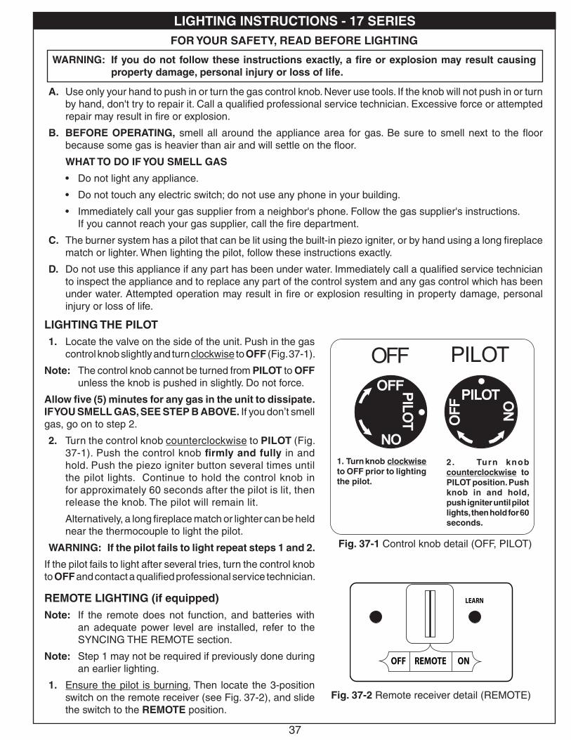
37
����� �����
���
��� �
���
����������
��� ���
����
���
����
���
������
����
����
����
��
FOR YOUR SAFETY, READ BEFORE LIGHTING
WARNING: If you do not follow these instructions exactly, a fire or explosion may result causing property damage, personal injury or loss of life.
A. Use only your hand to push in or turn the gas control knob. Never use tools. If the knob will not push in or turn by hand, don't try to repair it. Call a qualified professional service technician. Excessive force or attempted repair may result in fire or explosion.
B. BEFORE OPERATING, smell all around the appliance area for gas. Be sure to smell next to the floor because some gas is heavier than air and will settle on the floor.
WHAT TO DO IF YOU SMELL GAS
• Do not light any appliance.
• Do not touch any electric switch; do not use any phone in your building.
• Immediately call your gas supplier from a neighbor's phone. Follow the gas supplier's instructions. If you cannot reach your gas supplier, call the fire department.
C. The burner system has a pilot that can be lit using the built-in piezo igniter, or by hand using a long fireplace match or lighter. When lighting the pilot, follow these instructions exactly.
D. Do not use this appliance if any part has been under water. Immediately call a qualified service technician to inspect the appliance and to replace any part of the control system and any gas control which has been under water. Attempted operation may result in fire or explosion resulting in property damage, personal injury or loss of life.
LIGHTING THE PILOT1. Locate the valve on the side of the unit. Push in the gas
control knob slightly and turn clockwise to OFF (Fig. 37-1).
Note: The control knob cannot be turned from PILOT to OFF unless the knob is pushed in slightly. Do not force.
Allow five (5) minutes for any gas in the unit to dissipate. IF YOU SMELL GAS, SEE STEP B ABOVE. If you don’t smell gas, go on to step 2.
2. Turn the control knob counterclockwise to PILOT (Fig. 37-1). Push the control knob firmly and fully in and hold. Push the piezo igniter button several times until the pilot lights. Continue to hold the control knob in for approximately 60 seconds after the pilot is lit, then release the knob. The pilot will remain lit.
Alternatively, a long fireplace match or lighter can be held near the thermocouple to light the pilot.
WARNING: If the pilot fails to light repeat steps 1 and 2.
If the pilot fails to light after several tries, turn the control knob to OFF and contact a qualified professional service technician.
REMOTE LIGHTING (if equipped)Note: If the remote does not function, and batteries with
an adequate power level are installed, refer to the SYNCING THE REMOTE section.
Note: Step 1 may not be required if previously done during an earlier lighting.
1. Ensure the pilot is burning. Then locate the 3-position switch on the remote receiver (see Fig. 37-2), and slide the switch to the REMOTE position.
Fig. 37-1 Control knob detail (OFF, PILOT)
1. Turn knob clockwise to OFF prior to lighting the pilot.
LEARN
REMOTE ONOFF
LO/OFF
ON/HI
Fig. 37-2 Remote receiver detail (REMOTE)
LIGHTING INSTRUCTIONS - 17 SERIES
2. Turn knob counterclockwise to PILOT position. Push knob in and hold, push igniter until pilot lights, then hold for 60 seconds.
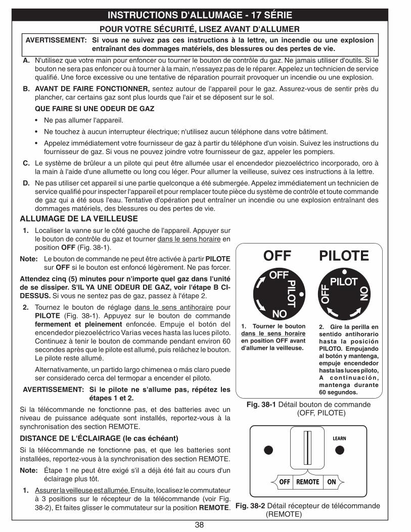
38
����� �����
���
��� �
���
����������
��� ���
����
���
����
���
������
����
����
����
��
POUR VOTRE SÉCURITÉ, LISEZ AVANT D'ALLUMERAVERTISSEMENT: Si vous ne suivez pas ces instructions à la lettre, un incendie ou une explosion
entraînant des dommages matériels, des blessures ou des pertes de vie.
A. N'utilisez que votre main pour enfoncer ou tourner le bouton de contrôle du gaz. Ne jamais utiliser d'outils. Si le bouton ne sera pas enfoncer ou à tourner à la main, n'essayez pas de le réparer. Appelez un technicien de service qualifié. Une force excessive ou une tentative de réparation pourrait provoquer un incendie ou une explosion.
B. AVANT DE FAIRE FONCTIONNER, sentez autour de l'appareil pour le gaz. Assurez-vous de sentir près du plancher, car certains gaz sont plus lourds que l'air et se déposent sur le sol.
QUE FAIRE SI UNE ODEUR DE GAZ
• Ne pas allumer l'appareil.
• Ne touchez à aucun interrupteur électrique; n'utilisez aucun téléphone dans votre bâtiment.
• Appelez immédiatement votre fournisseur de gaz à partir du téléphone d'un voisin. Suivez les instructions du fournisseur de gaz. Si vous ne pouvez joindre votre fournisseur de gaz, appeler les pompiers.
C. Le système de brûleur a un pilote qui peut être allumée usar el encendedor piezoeléctrico incorporado, oro à la main à l'aide d'une allumette ou long cou léger. Pour allumer la veilleuse, suivez ces instructions à la lettre.
D. Ne pas utiliser cet appareil si une partie quelconque a été submergée. Appelez immédiatement un technicien de service qualifié pour inspecter l'appareil et pour remplacer toute pièce du système de contrôle et toute commande de gaz qui a été sous l'eau. Tentative d'opération peut entraîner un incendie ou une explosion entraînant des dommages matériels, des blessures ou des pertes de vie.
ALLUMAGE DE LA VEILLEUSE1. Localiser la vanne sur le côté gauche de l'appareil. Appuyer sur
le bouton de contrôle du gaz et tourner dans le sens horaire en position OFF (Fig. 38-1).
Note: Le bouton de commande ne peut être activée à partir PILOTE sur OFF si le bouton est enfoncé légèrement. Ne pas forcer.
Attendez cinq (5) minutes pour n'importe quel gaz dans l'unité de se dissiper. S'IL YA UNE ODEUR DE GAZ, voir l'étape B CI-DESSUS. Si vous ne sentez pas de gaz, passez à l'étape 2.
2. Tournez le bouton de réglage dans le sens antihoraire pour PILOTE (Fig. 38-1). Appuyez sur le bouton de commande fermement et pleinement enfoncée. Empuje el botón del encendedor piezoeléctrico Varias veces hasta las luces piloto. Continuez à tenir le bouton de commande pendant environ 60 secondes après que le pilote est allumé, puis relâchez le bouton. Le pilote reste allumé.
Alternativamente, un partido largo chimenea o más claro puede ser considerado cerca del termopar a encender el piloto.
AVERTISSEMENT: Si le pilote ne s'allume pas, répétez les étapes 1 et 2.
Si la télécommande ne fonctionne pas, et des batteries avec un niveau de puissance adéquate sont installés, reportez-vous à la synchronisation des section REMOTE.
DISTANCE DE L'ÉCLAIRAGE (le cas échéant)
Si la télécommande ne fonctionne pas, et que les batteries sont installées, reportez-vous à la synchronisation des section REMOTE.
Note: Étape 1 ne peut être exigé s'il a déjà été fait au cours d'un éclairage plus tôt.
1. Assurer la veilleuse est allumée. Ensuite, localisez le commutateur à 3 positions sur le récepteur de la télécommande (voir Fig. 38-2), Et faites glisser le commutateur sur la position REMOTE.
Fig. 38-1 Détail bouton de commande (OFF, PILOTE)
1. Tourner le bouton dans le sens horaire en position OFF avant d'allumer la veilleuse.
LEARN
REMOTE ONOFF
LO/OFF
ON/HI
Fig. 38-2 Détail récepteur de télécommande (REMOTE)
OFF PILOTE
INSTRUCTIONS D'ALLUMAGE - 17 SÉRIE
2. Gire la perilla en sentido antihorario hasta la posición PILOTO. Empujando al botón y mantenga, empuje encendedor hasta las luces piloto, A cont inuac ión , mantenga durante 60 segundos.
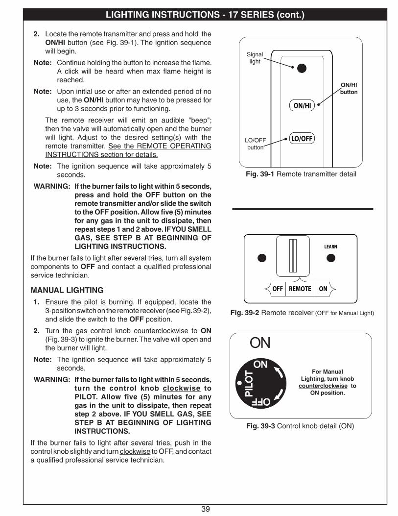
39
2. Locate the remote transmitter and press and hold the ON/HI button (see Fig. 39-1). The ignition sequence will begin.
Note: Continue holding the button to increase the flame. A click will be heard when max flame height is reached.
Note: Upon initial use or after an extended period of no use, the ON/HI button may have to be pressed for up to 3 seconds prior to functioning.
The remote receiver will emit an audible "beep"; then the valve will automatically open and the burner will light. Adjust to the desired setting(s) with the remote transmitter. See the REMOTE OPERATING INSTRUCTIONS section for details.
Note: The ignition sequence will take approximately 5 seconds.
WARNING: If the burner fails to light within 5 seconds, press and hold the OFF button on the remote transmitter and/or slide the switch to the OFF position. Allow five (5) minutes for any gas in the unit to dissipate, then repeat steps 1 and 2 above. IF YOU SMELL GAS, SEE STEP B AT BEGINNING OF LIGHTING INSTRUCTIONS.
If the burner fails to light after several tries, turn all system components to OFF and contact a qualified professional service technician.
MANUAL LIGHTING1. Ensure the pilot is burning. If equipped, locate the
3-position switch on the remote receiver (see Fig. 39-2), and slide the switch to the OFF position.
2. Turn the gas control knob counterclockwise to ON (Fig. 39-3) to ignite the burner. The valve will open and the burner will light.
Note: The ignition sequence will take approximately 5 seconds.
WARNING: If the burner fails to light within 5 seconds, turn the control knob clockwise to PILOT. Allow five (5) minutes for any gas in the unit to dissipate, then repeat step 2 above. IF YOU SMELL GAS, SEE STEP B AT BEGINNING OF LIGHTING INSTRUCTIONS.
If the burner fails to light after several tries, push in the control knob slightly and turn clockwise to OFF, and contact a qualified professional service technician.
Fig. 39-1 Remote transmitter detail
LEARN
REMOTE ONOFF
LO/OFF
ON/HI
Fig. 39-2 Remote receiver (OFF for Manual Light)
����� �����
���
��� �
���
����������
��� ���
����
���
����
���
������
����
����
����
��
Fig. 39-3 Control knob detail (ON)
For Manual Lighting, turn knob
counterclockwise to ON position.
LEARN
REMOTE ONOFF
LO/OFF
ON/HI
ON/HI button
LO/OFF button
Signal light
LIGHTING INSTRUCTIONS - 17 SERIES (cont.)

40
2. Localiser la télécommande et appuyez sur le touche ON/HI (voir Fig. 40-1). La séquence d'allumage commence.
Note: Continuez à maintenir le touche pour augmenter la flamme. Un clic se fait entendre lorsque la hauteur max de flamme est atteinte.
Note: Dès la première utilisation ou après une longue période de non utilisation, le touche ON/HI peut être pressée pour 3 secondes avant de fonctionnement.
Le récepteur de la télécommande émettra un «bip» sonore, puis la vanne s'ouvre automatiquement et le brûleur s'allume. Choisissez le réglage souhaité (s) avec la télécommande. Voir la section INSTRUCTIONS DE FONCTIONNEMENT A DISTANCE pour plus de détails.
Note: La séquence d'allumage dure environ 5 secondes.
WARNING: Si le brûleur ne s'allume pas dans les 5 secondes, appuyez et maintenez le bouton OFF de la télécommande et / ou faites glisser le commutateur à la position OFF. Permettre aux cinq (5) minutes pour tout gaz dans l'unité à se dissiper, puis répétez les étapes 1 et 2 ci-dessus. SI VOUS UNE ODEUR DE GAZ, voir l'étape B AU DÉBUT DE DIRECTIVES D'ALLUMAGE.
Si le brûleur ne s'allume pas après plusieurs essais, tournez tous les composants du système à OFF et contactez un technicien qualifié.
ALLUMAGE MANUEL1. Assurer la veilleuse est allumée. Si vous êtes équipé,
localisez le commutateur à 3 positions sur le récepteur de la télécommande (voir Fig. 40-2), Et faites glisser le commutateur sur la position OFF.
2. Tournez le bouton de contrôle du gaz dans le sens antihoraire sur ON (Fig. 40-3) pour allumer le brûleur. La vanne s'ouvre et le brûleur s'allume.
Note: La séquence d'allumage dure environ 5 secondes.
WARNING: Si le brûleur ne s'allume pas dans les 5 secondes, tournez le bouton de commande vers la droite pour PILOT. Permettre aux cinq (5) minutes pour tout gaz de l'unité de dissiper, puis répétez l'étape 2 ci-dessus. SI VOUS UNE ODEUR DE GAZ, voir l'étape B AU DÉBUT DE instructions d'allumage.
Si le brûleur ne s'allume pas après plusieurs tentatives, appuyez sur le bouton de commande et tournez légèrement à OFF et contactez un technicien qualifié.
Fig. 40-1 Détail télécommande
LEARN
REMOTE ONOFF
LO/OFF
ON/HI
Fig. 40-2 Récepteur de la télécommander (OFF pour Light Manuel)
����� �����
���
��� �
���
����������
��� ���
����
���
����
���
������
����
����
����
��
Fig. 40-3 Détail bouton de commande (SUR)
Pour l'éclairage manuel, tournez
le bouton dans le sens antihoraire à la
position ON.
SUR
LEARN
REMOTE ONOFF
LO/OFF
ON/HI
feux de signalisation
ON/HI(sur / haute) touche
LO/OFF (faible /
éteindre)touche
INSTRUCTIONS D'ALLUMAGE - 17 SÉRIE (cont.)

41
SHUTTING DOWNMAIN BURNER ONLY (pilot will remain lit):
For remote shut down, press and hold the LO/OFF button on the remote transmitter until the burner shuts off. If remote is unavailable, slide the switch on the receiver to the OFF position. For manual shutdown, turn the control knob clockwise to PILOT.
BURNER AND PILOT (total shutdown):
If you do not plan on using your burner system for an extended period (4 days or more), you may extinguish the pilot. This will conserve energy and save you money.
Push in the control knob slightly and turn clockwise to OFF.
PILOT BURNER CHECK/ADJUSTMENTWith the pilot burner lit and the control knob in the pilot position, check the pilot system for proper flame size and appearance (see Fig. 41-1). The pilot adjustment screw is located on the front of the gas valve (see Fig. 41-1). Using a small flat head screwdriver, adjust the pilot screw to properly size the flames. Turning the screw clockwise will lower the flames, and turning it counterclockwise will raise them. Be careful not to back the screw out of its threads.
The pilot flame should be a quiet, soft blue flame with yellow tipping that encircles the thermocouple tip.
Fig. 41-1 Pilot adjustment detail
Pilot adjustment screw
PILOT VALVE
ORIENTATIONNote: If the remote does not function, and batteries with
an adequate power level are installed, refer to the SYNCING THE REMOTE section.
Prior to remote transmitter use, light the appliance per the REMOTE LIGHTING section. Familiarize yourself with the transmitter buttons, as illustrated in Fig. 41-2.
Identify the transmitter buttons:
• ON/HI BUTTON: This button turns the burner ON (when the pilot is lit), and increases the flame height.
• LO/OFF BUTTON: This button decreases the flame height and turns the burner OFF (pilot will remain lit).
FLAME HEIGHTThe flame height may be adjusted via the remote transmitter. Press and hold the ON/HI button to increase the flame height. Press and hold the LO/OFF button to decrease the flame height. A click will be heard when the max/minimum setting is reached.
Note: Continuing to hold the LO/OFF button will turn off the burner. The pilot will remain lit.
Fig. 41-2 Remote transmitter detailLEARN
REMOTE ONOFF
LO/OFF
ON/HI
ON/HI button
LO/OFF button
Signal light
Thermocouple
LIGHTING INSTRUCTIONS - 17 SERIES (cont.)
REMOTE OPERATING INSTRUCTIONS - 17 SERIES
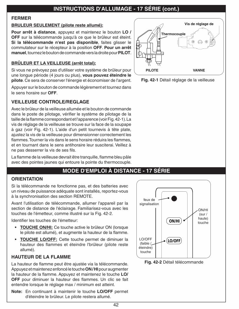
42
FERMERBRULEUR SEULEMENT (pilote reste allumé):
Pour arrêt à distance, appuyez et maintenez le bouton LO / OFF sur la télécommande jusqu'à ce que le brûleur est éteint. Si la télécommande n'est pas disponible, faites glisser le commutateur sur le récepteur à la position OFF. Pour un arrêt manuel, tournez le bouton de commande vers la droite pour PILOT.
BRÛLEUR ET LA VEILLEUSE (arrêt total):
Si vous ne prévoyez pas d'utiliser votre système de brûleur pour une longue période (4 jours ou plus), vous pouvez éteindre le pilote. Ce sera de conserver l'énergie et économiser de l'argent.
Appuyer sur le bouton de commande légèrement et tournez dans le sens horaire sur OFF.
VEILLEUSE CONTROLE/REGLAGEAvec le brûleur de la veilleuse allumée et le bouton de commande dans le poste de pilotage, vérifier le système de pilotage de la taille de la flamme correspondant et l'apparence (voir Fig. 42-1). La vis de réglage de la veilleuse se trouve sur la face de la soupape à gaz (voir Fig. 42-1). L'aide d'un petit tournevis à tête plate, ajustez la vis de la veilleuse pour dimensionner correctement les flammes. Tourner la vis dans le sens horaire réduira les flammes, et en tournant dans le sens antihoraire leur susciterai. Veillez à ne pas desserrer la vis de ses fils.
La flamme de la veilleuse devrait être tranquille, flamme bleu pâle avec des pointes jaunes qui entoure la pointe du thermocouple.
Fig. 42-1 Détail réglage de la veilleuse
Vis de réglage de
ORIENTATIONSi la télécommande ne fonctionne pas, et des batteries avec un niveau de puissance adéquate sont installés, reportez-vous à la synchronisation des section REMOTE.
Avant l'utilisation de télécommande, allumer l'appareil par la section de distance de l'éclairage. Familiarisez-vous avec les touches de l'émetteur, comme illustré sur la Fig. 42-2.
Identifier les touches de l'émetteur:
• TOUCHE ON/HI: Ce touche active le brûleur ON (lorsque le pilote est allumé), et augmente la hauteur de la flamme.
• TOUCHE LO/OFF: Cette touche permet de diminuer la hauteur des flammes et éteindre l'brûleur (pilote reste allumé).
HAUTEUR DE LA FLAMMELa hauteur de flamme peut être ajustée via la télécommande. Appuyez et maintenez enfoncé le touche ON / HI pour augmenter la hauteur de la flamme. Appuyez et maintenez le touche LO/OFF pour diminuer la hauteur des flammes. Un clic se fait entendre lorsque le réglage max / minimum est atteint.
Note: En continuant à maintenir le touche LO/OFF permet d'éteindre le brûleur. Le pilote restera allumé.
PILOTE VANNE
Fig. 42-2 Détail télécommandeLEARN
REMOTE ONOFF
LO/OFF
ON/HI
feux de signalisation
ON/HI(sur /
haute) touche
LO/OFF (faible /
éteindre)touche
Thermocouple
INSTRUCTIONS D'ALLUMAGE - 17 SÉRIE (cont.)
MODE D'EMPLOI À DISTANCE - 17 SÉRIE
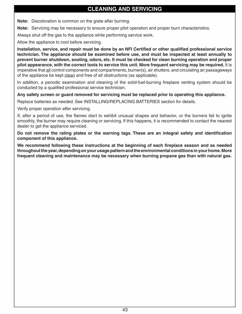
43
Note: Discoloration is common on the grate after burning.
Note: Servicing may be necessary to ensure proper pilot operation and proper burn characteristics.
Always shut off the gas to the appliance while performing service work.
Allow the appliance to cool before servicing.
Installation, service, and repair must be done by an NFI Certified or other qualified professional service technician. The appliance should be examined before use, and must be inspected at least annually to prevent burner shutdown, sooting, odors, etc. It must be checked for clean burning operation and proper pilot appearance, with the correct tools to service this unit. More frequent servicing may be required. It is imperative that all control components and compartments, burner(s), air shutters, and circulating air passageways of the appliance be kept clean and free of all obstructions (as applicable).
In addition, a periodic examination and cleaning of the solid-fuel-burning fireplace venting system should be conducted by a qualified professional service technician.
Any safety screen or guard removed for servicing must be replaced prior to operating this appliance.
Replace batteries as needed. See INSTALLING/REPLACING BATTERIES section for details.
Verify proper operation after servicing.
If, after a period of use, the flames start to exhibit unusual shapes and behavior, or the burners fail to ignite smoothly, the burner may require cleaning or servicing. If this happens, it is recommended to contact the nearest dealer to get the appliance serviced.
Do not remove the rating plates or the warning tags. These are an integral safety and identification component of this appliance.
We recommend following these instructions at the beginning of each fireplace season and as needed throughout the year, depending on your usage pattern and the environmental conditions in your home. More frequent cleaning and maintenance may be necessary when burning propane gas than with natural gas.
CLEANING AND SERVICING

44
CLEANING AND SERVICING (cont.)
Fig. 44-2 Flame appearance
LEARN
REMOTE ONOFF
LO/OFF
ON/HI
Fig. 44-1 Remote receiver sync detail
Observe the flames. The main burner flames should be blue at the base and a combination of blue/yellow at the body and at the tips. They should be approximately 5-8" above the logs, with the center flame being the tallest. The ember flames should be 1/4" above the embers (See 44-2 for example.)
FLAME DESCRIPTION
LEARN
REMOTE ONOFF
LO/OFF
ON/HI
Fig. 44-1 Remote receiver sync detail
SYNCING THE REMOTE SYSTEM (if applicable)Ensure the burner system is off and completely cool.
Locate the 3-position switch on the remote receiver and slide it to the REMOTE position. Use the tip of a pen or a wire clip to push the LEARN button and release. See Fig. 44-1. A beep will be heard. Then press and hold the ON or ON/HI button on the remote transmitter; a series of beeps should be heard. The remote system is now synced. Refer to the LIGHTING INSTRUCTIONS to test.

45
TROUBLESHOOTINGPOSSIBLE CAUSE SOLUTIONS
BURNER SHUTTING DOWN DURING OPERATIONA. Insufficient or excessive gas
pressureA1. Check gas pressure (Read D.- F. of IMPORTANT PRE-INSTALLATION AND
FIREPLACE SAFETY INFORMATION section, & check with local gas company).
A2. Other gas appliances may be on the same gas line, dropping gas pressure to log set. Check pressures with everything operating to ensure adequate pressure.
B. Log placement B. Reference the LOG PLACEMENT section in this manual for recommended log positioning.
C. Flue area, f ireplace, or damper dirty from soot
C. Clean around, above, and under damper thoroughly. Clean fireplace, removing loose material, including soot and creosote.
D. Fireplace too small for unit D. Ensure minimum requirements are met (see SPECIFICATIONS section).
E. Pi lo t f l ame l i f t i ng o f f thermocouple/generator
E. Check gas pressure (see section A1).
F. Pilot (remote compatible) F. Contact your dealer for instructions on replacement.
G. Blockages on burner G. Vacuum any lava granules or material that may have fallen onto burner port area.
PILOT WILL NOT LIGHTA. P i l o t f l ame l i f t i ng o f f
thermocouple/generatorA. Check gas pressure (see Section 1, A1 of this table).
B. Electronic spark not lighting pilot
B1. Check to ensure sparking when activated.Note: You may need to turn or press igniter several times to ignite pilot. See
LIGHTING INSTRUCTIONS for your control valve.B2. Pilot is sparking to screen, not to electrode (if applicable). Adjust screen
to 1/4" minimum clearance from pilot. (See ELECTRONIC PILOT TROUBLESHOOTING section for details.)
C. Igniter electrode wire loose C. Check wiring and reconnect any loose wiring.
D. Gas supply of f /manual shutoff valve closed
D. Turn on gas supply or open manual shutoff valve.
E. Air in gas line E. Bleed gas supply line and repeat LIGHTING INSTRUCTIONS until air is removed.
F. Pilot hood blocked F. Check for debris or dirt / Clean pilot
G. Dead batteries (if applicable) G. Replace batteries as needed.
2
1
LOW FLAME HEIGHTA. Gas pressure A. Check gas pressure (see Section 1, A1 of this table).
B. Valve not fully open B. Open valve fully.
C. Blockage or kink in flex connector kit, plumbing, or burner orifice
C. Clean out blockage. If flex connector is kinked, replace it.
D. Remote set on low flame (if option available)
D. Adjust flame with remote transmitter.
E. Incorrect media (sand or vermiculite) for gas type
E. Contact dealer for proper media (sand or vermiculite).
3
BURNER NOT BURNING EVENLYA. Burner ports clogged A. Clean burner ports.
B. Media may be packed down too tightly
B. Loosen media around burner pipe by running a flathead screwdriver along both sides of the pipe. Even out media in burner pan.
C. Top burner lights; bottom burner has delayed ignition.
C1. Check gas pressure. Can be caused by too small of a gas line (see Section 1, A1 of this table).
C2. Low propane tank level. Vacuum burner tube for soot blockage and fill propane tank.
4

46
TROUBLESHOOTING (Cont.)
SMOKING AND/OR SOOTINGA. Poor draft or downdraft A. Check for chimney blockage. Be sure chimney is at least
3' taller than anything within 10' of it in all directions. If not, consult a chimney sweep. A chimney cap or fan may help.
B. Damper closed B. Ensure that damper is open.
C. Burner is positioned too close to front of firebox C. Move burner system to the center of the firebox.
D. Improper media placement D. See INSTALLATION section for proper media placement.
E. Air mixer on propane set closed (if applicable) E. Open air mixer completely.
F. Air shutters blocked (if applicable) F. Air shutters are blocked with debris. Vacuum debris away from air shutter.
G. Log placement G. See solution in Section 1, B.
H. Using natural-gas burner on propane gas or propane burner on natural gas
H. If gas listed on nameplate does not match gas you are burning, shut down burner system immediately. Call dealer.
I. Adding any accessories to burner system I. Shut down burner system and take off any accessories that do not belong with the system.
PILOT WILL NOT STAY LITA. Valve won’t hold A. Contact your dealer for instructions on replacement.
B. Pilot hood not aimed at thermocouple B. Pilot hood bent; replace pilot or angle pilot hood properly so pilot flame hits thermocouple.
C. Pilot line bent / kinked at connection to valve C. Replace pilot line.
D. Thermocouple is loose D. Tighten thermocouple nut at gas control valve. (Do not over tighten.)
E. Thermocouple cracked or worn out E. Replace thermocouple.
F. Excessive down draft F. Install chimney cap / Outside chimney too close to other peaks / Check chimney flue for proper height / Poorly designed chimney.
6
7
POSSIBLE CAUSE SOLUTIONS
ODORSA. Gas leak A. Shut off gas, if possible. Follow instructions on front page. Have a qualified
professional installer or the gas company correct all leaks.
B. New home, new carpet, or new paint
B. When these odors are drawn into the fireplace, this may cause objectionable odors. Thoroughly ventilate the area before restarting your log set.
C. Damper closed C. Ensure that damper is open.
5
FLAME AT AIR MIX / ORIFICE (PROPANE MODELS)A. Burner ports clogged A. Clean burner ports.
B. Gas pressure B. Check gas pressure (see Section 1, A1 of this table).
C. Incorrect media for propane gas and/or media may be packed down too tightly
C. Ensure proper vermiculite media is used with propane gas. Loosen media around burner pipe by running a flathead screwdriver along both sides of pipe. Even out media in pan.
9
BURNER WILL NOT TURN ONA. Low/dead batteries in remote transmitter
AND/OR switch/receiver box (if applicable)A. Replace batteries as needed.
8

47
Detail AHood
Spark electrode
Electrode Ceramic
Threaded barrel
Retainer nuts
1/8"min. gap
Electrode (A)
When adjusting the spark electrode (if necessary); NEVER adjust the electrode by bending the wire. ALWAYS adjust the electrode by loosening the retainer nut(s), then adjust accordingly.
The minimum gap between the spark electrode/heat sensor and the pilot flame hood is 1/8". The maximum is 5/32".
If the electrode ceramic is loose in the threaded barrel; the pilot assembly must be replaced.
DO NOT bundle tightly
together as shown
Ensure that spade terminals (S and I) are attached securely
Ensure that multi-wire connector is properly
engaged
Detail C
Control Module(DESIGN MAY VARY)
CORRECT INCORRECT
Spade Terminal Detail
Assembly Wires (C)
DO NOT bundle the excess pilot assembly wires tightly together as this can reduce the intensity of the spark.
Detail BTerminal Connections (B)
All of the connections on the control module must be properly attached. If the spade terminals are loose; inspect to ensure they correctly appear as detailed below. Use needle nose pliers to clamp down on the center/sides of the terminals if needed (to provide a tight fit.) See Fig B-3 below.
Fig. A-1
(Fig. B-2)
Tighten terminals if needed
(Fig. B-3)
(Fig. C-1)
(Fig. B-1)
1/8"min. gap
Heat sensor
Screen
Pilotassembly
1/4"1/8"
sensorDetail D
The clearances between the sensor, the screen, and pilot assembly must be maintained to ensure proper igintion.
Heat sensorClearances (D)
ELECTRONIC PILOT TROUBLESHOOTING (IF APPLICABLE)

48Robert H. Peterson Co. • 14724 East Proctor Avenue • City of Industry, CA 91746
Quality Check Date:_________________Burner Orifices Nat. L.P. Leak Test: ___________ Model#: ___________________
Main: ____ ____ Burn Test: ___________ Serial#: ___________________
Other: ____ ____ Gas Type: Nat. / L.P. Air Shutter: ___________________
Inspector: ___________________
FOR USE IN THE COMMONWEALTH OF MASSACHUSETTSINSTALLATION OF THIS APPLIANCE MUST BE IN COMPLIANCE WITH 248 CMR: BOARD OF STATE
EXAMINERS OF PLUMBERS AND GAS FITTERS AND PERFORMED BY A MASSACHUSETTS LICENSED PLUMBER OR GAS FITTER ONLY.
CONNECTOR KITS USED FOR INSTALLATION AND OPERATION OF THIS APPLIANCE MUST NOT BE MORE THAN 36" IN LENGTH.
FIREPLACE DAMPER MUST BE REMOVED OR PERMANENTLY FIXED/WELDED IN FULL OPEN POSITION PRIOR TO INSTALLING THIS PRODUCT.
A COPY OF YOUR SALES SLIP FOR PROOF OF PURCHASE IS REQUIRED
This warranty applies to the original purchaser for products which are installed in the United States or Canada and which are operated and maintained as intended for single family residential usage. This warranty is valid only with proof of purchase, commence on the date of purchase, and terminates (both as to original and any replacement products) on the anniversary date of the original purchase of the product per the above schedules.
This warranty covers defects in material and workmanship. This warranty does not cover parts which become defective as a result of negligence, misuse, use not in compliance with the Installation and Owner’s Manual, accidental damage, improper handling, improper storage, improper installation, lack of required routine maintenance (as specified in the Installation and Owner’s Manual), electrical damage, local gas impurities or failure to protect against combustibles. Product must be installed (and gas must be connected) as specified in the Installation and Owner’s Manual by a qualified professional installer. Modifications to products which are not specifically authorized will void this warranty. Accessories, parts, valves, remotes, etc. when used must be Peterson products or this warranty is void. Warrantied items will be repaired or replaced at Peterson’s sole discretion. This warranty does not apply to rust, corrosion, oxidation, or discoloration unless the affected part becomes inoperable.
This warranty does not cover labor or labor related charges, except as provided by separate specific written programs from the Peterson Co. All repair work must be performed by a qualified professional service person and requires prior approval of Peterson.
Peterson may require the defective product or part to be returned to the factory to determine the cause of failure. Peterson will pay freight charges if the product or part is determined to be defective. This warranty does not cover breakage in shipment from our (Independent) distributor to its customer if the damage is determined to have occurred during that shipment.
This warranty specifically excludes liability for indirect, incidental, or consequential damages. Some states and provinces do not allow the exclusion or limitation of incidental or consequential damages, so the above exclusion may not apply to you. This warranty gives you specified legal rights, and you may have other rights that vary from state to state or province.
For additional information regarding this warranty, or to place a warranty claim, contact the R. H. Peterson dealer where the product was purchased.
When contacting your Peterson dealer or the R. H. Peterson Co., please provide the following information:
- Your name, address, telephone number, e-mail- Sales receipt showing where purchased and date purchased- Model number, serial number of product, date code- Relevant information: installer, additions, repairs, when defect was first noted
TO REGISTER YOUR PRODUCT ONLINE GO TO: WWW.RHPETERSON.COM,AND CLICK ON PRODUCT REGISTRATION. THANK YOU FOR YOUR PURCHASE.
PETERSON INDOOR VENTED DECORATIVE GAS APPLIANCELIMITED WARRANTY
Robert H. Peterson Co. ("RHP") warrants your Real Fyre® vented decorative gas appliance to be free from defects in material and workmanship. This warranty is for indoor use only.
Peterson vented ceramic refractory gas logs are warranted for as long as you own them (lifetime).
Peterson vented burner assemblies excluding valves, pilots, and controls are WARRANTED for TEN (10) YEARS.
Peterson glass, gems, nuggets, and fiber-ceramic blend gas logs are warranted for FIVE (5) YEARS.
SPK-26 controls are warranted for THREE (3) YEARS.
APK-17 controls (including -17 valve) are warranted for TWO (2) YEARS.
All other Peterson valves, pilots, and controls are warranted for ONE (1) YEAR (excluding batteries).
WARRANTY