G45-GL VENTED GAS BURNER SYSTEMS (MANUALLY LIGHTED)RE 4 - 2004061145 1 L-A2-232 Robert H. Peterson...
18
1 REV 4 - 2102080705 L-A2-232 Robert H. Peterson Co. • 14724 East Proctor Avenue • City of Industry, CA 91746 Robert H. Peterson Co. • 14724 East Proctor Avenue • City of Industry, CA 91746 Robert H. Peterson Co. • 14724 East Proctor Avenue • City of Industry, CA 91746 The Real Fyre burner system is to be installed only in a solid-fuel burning fireplace with a working flue and constructed of noncombustible material.The installation, including provisions for combustion and ventilation air must conform with the National Fuel Gas Code, ANSI Z223.1/NFPA 54, or the CSA B149.1, Natural Gas and Propane Installation Code, and applicable local building codes. A damper clamp, which must be permanently installed, is included to maintain the minimum permanent vent opening and to prevent full closure of the damper. The chimney damper MUST be fully opened when burning the unit. The unit is designed to burn with yellow flames; thus adequate ventilation is absolutely necessary. This appliance is designed as an attended appliance. DO NOT leave this appliance burning when unattended. To comply with certification, listings, and building code acceptances, and for safe operation and proper performance of this burner system, use ONLY Peterson parts and accessories. Use of other controls, parts, and accessories that are not designed for use with Real Fyre burner systems is prohibited and will void all warranties, certifications, listings, and building code approvals, and may cause property damage, personal injury, or loss of life. *Note: Solid-fuels shall not be burned in a fireplace where a decorative appliance is installed. IMPORTANT: READ THESE INSTRUCTIONS CAREFULLY BEFORE STARTING INSTALLATION OF THE UNIT. Do not store or use gasoline or other flammable vapors and liquids in the vicinity of this or any other appliance. WHAT TO DO IF YOU SMELL GAS: • Open a window. • Do not try to light any appliance. • Do not touch any electrical switch; do not use any phone in the building. • Immediately call the gas supplier from a neighbor’s phone. Follow gas supplier’s instructions. • If you cannot reach the gas supplier, call the fire department. WARNING If the information in this manual is not followed exactly, a fire or explosion may result, causing property damage, personal injury, or loss of life. This appliance is only for use with the type of gas indicated on the rating plate. Installation and service must be performed by a qualified professional service technician, service agency, or the gas supplier. INSTALLER: Leave this manual with the appliance. CONSUMER: Retain this manual for future reference. INSTALLATION & OWNER’S MANUAL G45-GL VENTED GAS BURNER SYSTEMS (MANUALLY LIGHTED) Burner Systems: G45-GL-16/19(P) G45-GL-18(P) G45-GL-24(P) G45-GL-30(P) G45-GL-36(P) G45-GL-42(P) G45-GL-48(P) G45-GL-60(P) For use w/ propane or natural gas FOR INSTALLATION IN SEE-THRU SOLID-FUEL BURNING FIREPLACES* Listed to: to: Decorative Log Sets for Installation in Wood-Burning Fireplaces RGA2-72 (16/19" - 30" models) Listing No. 1188
Transcript of G45-GL VENTED GAS BURNER SYSTEMS (MANUALLY LIGHTED)RE 4 - 2004061145 1 L-A2-232 Robert H. Peterson...

1REV 4 - 2102080705 L-A2-232
Robert H. Peterson Co. • 14724 East Proctor Avenue • City of Industry, CA 91746 Robert H. Peterson Co. • 14724 East Proctor Avenue • City of Industry, CA 91746 Robert H. Peterson Co. • 14724 East Proctor Avenue • City of Industry, CA 91746
The Real Fyre burner system is to be installed only in a solid-fuel burning fireplace with a working flue and constructed of noncombustible material. The installation, including provisions for combustion and ventilation air must conform with the National Fuel Gas Code, ANSI Z223.1/NFPA 54, or the CSA B149.1, Natural Gas and Propane Installation Code, and applicable local building codes.A damper clamp, which must be permanently installed, is included to maintain the minimum permanent vent opening and to prevent full closure of the damper.The chimney damper MUST be fully opened when burning the unit. The unit is designed to burn with yellow flames; thus adequate ventilation is absolutely necessary.This appliance is designed as an attended appliance. DO NOT leave this appliance burning when unattended.To comply with certification, listings, and building code acceptances, and for safe operation and proper performance of this burner system, use ONLY Peterson parts and accessories. Use of other controls, parts, and accessories that are not designed for use with Real Fyre burner systems is prohibited and will void all warranties, certifications, listings, and building code approvals, and may cause property damage, personal injury, or loss of life.*Note: Solid-fuels shall not be burned in a fireplace
where a decorative appliance is installed.
IMPORTANT: READ THESE INSTRUCTIONS CAREFULLY BEFORE STARTING INSTALLATION OF THE UNIT.
Do not store or use gasoline or other flammable vapors and liquids in the vicinity of this or any other appliance.WHAT TO DO IF YOU SMELL GAS:
• Open a window.
• Do not try to light any appliance.
• Do not touch any electrical switch; do not use any phone in the building.
• Immediately call the gas supplier from a neighbor’s phone. Follow gas supplier’s instructions.
• If you cannot reach the gas supplier, call the fire department.
WARNINGIf the information in this manual is not followed exactly, a fire or explosion may result, causing property damage, personal injury, or loss of life.
This appliance is only for use with the type of gas indicated on the rating plate.
Installation and service must be performed by a qualified professional service technician, service agency, or the gas supplier.
INSTALLER:Leave this manual with the appliance.
CONSUMER:Retain this manual for future reference.
INSTALLATION & OWNER’S MANUAL
G45-GL VENTED GAS BURNER SYSTEMS (MANUALLY LIGHTED)
Burner Systems:G45-GL-16/19(P)
G45-GL-18(P)G45-GL-24(P)G45-GL-30(P)G45-GL-36(P)G45-GL-42(P)G45-GL-48(P)G45-GL-60(P)
For use w/ propane or natural gas
FOR INSTALLATION INSEE-THRU SOLID-FUEL BURNING FIREPLACES*
Listed to:to:
Decorative Log Sets for Installation in Wood-Burning Fireplaces
RGA2-72
(16/19" - 30" models)
Listing No. 1188

2REV 4 - 2102080705 L-A2-232
TABLE OF CONTENTS
GETTING STARTEDIMPORTANT PRE-INSTALLATION AND FIREPLACE SAFETY INFORMATION ������������������������������������������������������������ 3FIREPLACE OPERATING SAFETY INFORMATION �������������������������������������������������������������������������������������������������������� 4SPECIFICATIONS������������������������������������������������������������������������������������������������������������������������������������������������������������� 5DAMPER CLAMP INSTRUCTIONS ��������������������������������������������������������������������������������������������������������������������������������� 9G45-GL BURNER REPLACEMENT PARTS LIST ������������������������������������������������������������������������������������������������������������ 10
INSTALLATIONINSTALLATION ������������������������������������������������������������������������������������������������������������������������������������������������������������� 11
BURNER INSTALLATION �������������������������������������������������������������������������������������������������������������������������������������������� 11SAND/VERMICULITE AND SCREEN PLACEMENT ��������������������������������������������������������������������������������������������������������� 12GLASS/GEMS PLACEMENT ���������������������������������������������������������������������������������������������������������������������������������������� 13SECONDARY OPTIONS ���������������������������������������������������������������������������������������������������������������������������������������������� 13
USE, CARE, & SERVICELIGHTING INSTRUCTIONS ������������������������������������������������������������������������������������������������������������������������������������������ 14
FOR YOUR SAFETY, READ BEFORE LIGHTING ������������������������������������������������������������������������������������������������������������ 14TO SHUT OFF GAS TO THE APPLIANCE ���������������������������������������������������������������������������������������������������������������������� 14
CLEANING AND SERVICING ���������������������������������������������������������������������������������������������������������������������������������������� 15FLAME DESCRIPTION �������������������������������������������������������������������������������������������������������������������������������������������������� 15TROUBLESHOOTING ���������������������������������������������������������������������������������������������������������������������������������������������������� 16WARRANTY ������������������������������������������������������������������������������������������������������������������������������������������������������������������ 18

3
IMPORTANT PRE-INSTALLATION AND FIREPLACE SAFETY INFORMATION
A. BE CAREFUL: If not installed, serviced, and used correctly per these instructions, this product can cause serious personal injury, property damage, or loss of life.
B. WARNING: When installing in a solid-fuel-burning fireplace, the chimney flue, damper, and firebox must be thoroughly CLEANED of soot, creosote, ashes, and loose paint, and must be inspected by a qualified chimney cleaner. Some older fireplaces may need repair prior to installing this appliance.
C. The fireplace floor must be level and smooth.D. This appliance is only for use with the type of gas indicated on the rating plate.
CHECK GAS TYPE (natural or L.P.): The gas supply must be the same as stated on your burner system rating plate. If gas supply is different, DO NOT INSTALL. Contact your dealer for immediate assistance.
E. INSUFFICIENT GAS PRESSURE WILL KEEP THE UNIT FROM OPERATING PROPERLY. DO NOT USE IF GAS PRESSURE IS LOWER THAN THE MINIMUM REQUIREMENT.
F. The minimum inlet gas-supply pressure for purposes of input adjustment is 7" water column (w.c.) on natural gas and 11" w.c. on L.P. gas. Insufficient gas pressure will affect proper operation of the pilot (if equipped). Do not install this gas appliance if minimum pressure is not available. The maximum inlet gas-supply pressure is 10.5" w.c. on natural gas and 13" w.c. on L.P. gas. The L.P. source must be regulated, located outside, and hard-lined in (rigid pipe must come into the fireplace). DO NOT connect this appliance to an unregulated L.P. gas tank/cylinder. DO NOT locate the tank/cylinder inside of the home. DO NOT run a rubber hose or flex connector into the fireplace. Failure to follow these requirements can cause an explosion.
G. The gas piping system must be sized to provide minimum inlet pressure at the maximum flow rate (BTU/hr). Undue pressure loss will occur if the pipe is too small, or the run is too long. Gas supply pipe must be 1/2" minimum interior diameter. If the gas line is longer than 20', a larger diameter line may be necessary. Refer to the NFPA 54 guidelines for further details.
H. Input ratings shown in BTU per hour are for elevations up to 2,000 ft. For elevations above 2,000 ft., refer to the National Fuel Gas Code or contact manufacturer before installing this product.
I. This gas appliance and its main gas valve must be disconnected from the gas-supply piping system during any pressure testing of that system at test pressures in excess of 1/2 psig.
J. This gas appliance must be isolated from the gas-supply piping system by closing the equipment shutoff valve connected to the gas-supply line during any pressure testing of the gas-supply piping system at test pressures equal to or less than 1/2 psig.
K. To install the gas appliance in your fireplace, the fireplace MUST meet the minimum size requirements (see product specifications table in SPECIFICATIONS section).
L. This appliance may be installed in an aftermarket, permanently located, manufactured (mobile) home, where not prohibited by local codes. Installation of appliances designed for manufactured home (U.S. only) or mobile home installation must conform with the Standard CAN/CSA Z240 MH, Mobile Housing, in Canada, or with the Manufactured Home Construction and Safety Standard, Title 24 CFR, Part 3280, in the United States, or when such a standard is not applicable, ANSI/NCSBCS A225.1/NFPA 501A, Manufactured Home Installations Standard.
M. DO NOT install this burner system in a fireplace with an ash lip or recess greater than 3/4".N. If this burner system is installed in a fireplace with glass doors, and the doors have a frame that obstructs airflow
to the fireplace floor, the frame MUST have slots (above the fireplace floor) that allow adequate ventilation. The opening (with doors fully open) MUST meet the minimum fireplace size front width and height requirements. The glass doors MUST be fully open when the burner is in operation. See the SPECIFICATIONS section for details.ONLY REAL FYRE DECORATIVE MEDIA IS APPROVED FOR USE WITH THIS PRODUCT. See the MEDIA sections found under SPECIFICATIONS for details. Correct installation of the media (and burner assembly) is imperative to safe operation of your appliance. Problems WILL occur if all items are not properly installed.
CAUTION: Installation and repair must be done by an NFI Certified or other qualified professional installer. Installer: Carefully read these instructions before installing this gas burner system. Be sure you understand
all safety precautions and warnings contained in this manual.
GETTING STARTED
4
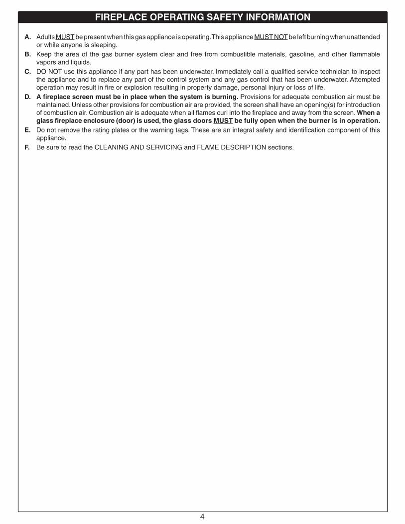
FIREPLACE OPERATING SAFETY INFORMATION
A. Adults MUST be present when this gas appliance is operating. This appliance MUST NOT be left burning when unattended or while anyone is sleeping.
B. Keep the area of the gas burner system clear and free from combustible materials, gasoline, and other flammable vapors and liquids.
C. DO NOT use this appliance if any part has been underwater. Immediately call a qualified service technician to inspect the appliance and to replace any part of the control system and any gas control that has been underwater. Attempted operation may result in fire or explosion resulting in property damage, personal injury or loss of life.
D. A fireplace screen must be in place when the system is burning. Provisions for adequate combustion air must be maintained. Unless other provisions for combustion air are provided, the screen shall have an opening(s) for introduction of combustion air. Combustion air is adequate when all flames curl into the fireplace and away from the screen. When a glass fireplace enclosure (door) is used, the glass doors MUST be fully open when the burner is in operation.
E. Do not remove the rating plates or the warning tags. These are an integral safety and identification component of this appliance.
F. Be sure to read the CLEANING AND SERVICING and FLAME DESCRIPTION sections.

5
Real Fyre gas burner systems must be installed only in a wood burning fireplace with the minimum firebox dimensions and venting requirements met (see following tables). This appliance is designed to burn with yellow flames; adequate ventilation is absolutely necessary.
SPECIFICATIONS
Product Specifications
Table 1 - Product BTUs
Burner Model(MATCH-LIT)
(NAT. GAS ONLY)
Minimum Fireplace SizeWidth *
Depth ‡ HeightFront Rear †
G45-GL-16/19 18" 15" 12" 16"
G45-GL-18/20 23" 17" 12" 16"
G45-GL-24 27" 22" 12" 16"
G45-GL-30 33" 26" 12" 16"
[G45-GL-36] 39" 33" 12" 16"
[G45-GL-42] 45" 39" 12" 16"
[G45-GL-48] 52" 44" 12" 16"
[G45-GL-60] 63" 55" 12" 16"
Important Information Regarding Dimensions
* These required widths allow for centering of the unit.
† Rear width is at corresponding depth.
‡ If an ash lip exists, the depth requirement begins inside of the lip (see FIREPLACE REQUIREMENTS section on following page).
[] Bracketed models indicate non-listed models.
▲ For Nat. gas models, a safety pilot kit is optional. For L.P. models, a kit is required (use the included SPK-26P, or an optional kit). See SAFETY PILOT KITS section on following page for more details.
Note: Table 3 dimensions apply for all safety pilot kits.
Burner Model
BTU RatingNat. Gas L.P. Gas
G45-GL-16/19 35k 28k
G45-GL-18/20 55k 38k
G45-GL-24 60k 50k
G45-GL-30 75k 60k
[G45-GL-36] 100k 70k
[G45-GL-42] 105k 85k
[G45-GL-48] 110k 90k
[G45-GL-60] 120k 105k
Table 2 - Minimum Fireplace Size: Match-lit (burner only)
Burner Model(WITH SAFETY PILOT KIT)
(NAT. OR L.P. GAS) ▲
Minimum Fireplace SizeWidth *
Depth ‡ HeightFront Rear †
G45-GL-16/19 26" 22" 12" 16"
G45-GL-18/20 29" 25" 12" 16"
G45-GL-24 34" 29" 12" 16"
G45-GL-30 39" 34" 12" 16"
[G45-GL-36] 46" 39" 12" 16"
[G45-GL-42] 51" 45" 12" 16"
[G45-GL-48] 58" 52" 12" 16"
[G45-GL-60] 69" 63" 12" 16"
Table 3 - Minimum Fireplace Size: Burner with safety pilot kit

6
Safety Control Valve SystemsTHIS UNIT COMES WITHOUT A VALVE INSTALLED. NATURAL GAS MODELS CAN BE INSTALLED DIRECTLY TO AND OPERATED BY YOUR FIREPLACE VALVE. FOR PROPANE MODELS, AN SPK SAFETY PILOT KIT IS INCLUDED AND MUST BE INSTALLED WITH THE BURNER.
Alternatively, your burner system can be installed with one of the optional R.H. Peterson safety control valve systems (see below). Contact your local Real Fyre dealer when ordering.
To comply with certification, listings, and building code acceptances, and for safe operation and proper performance of this burner system, you must use ONLY R.H. Peterson parts and accessories.
Table 4 - Optional Safety Control Valve Systems
Description ModelLow Profile, Safety Pilot Kit SPK-26(P)
High Capacity, Automatic Pilot Kit with basic transmitter & receiver APK-10(P)
Automatic Pilot Kit with basic transmitter & receiver APK-11(P)
Variable, Automatic Pilot Kit with basic transmitter & receiver APK-15(P)
Low Profile, Variable, Automatic Pilot Kit with basic transmitter & receiver APK-17(P)
Electronic Pilot Kit with on/off basic transmitter & receiver EPK-2(P)
110 Volt Powered Electronic, non-standing pilot system EPK-2M-AD(/LP)
110 Volt Powered Electronic, non-standing pilot system with variable flame height control EPK-2V(P)-TR
High Capacity, 110 Volt Powered Electronic, non-standing pilot system w/variable flame height control EPK-3V(P)-TR
Electronic Pilot System with hot surface ignition and smart valve EPK-05(P)
Manual On/Off Valve with extension and knob handle or rod handle AV-17 / AV-18
Fireplace RequirementsThese requirements MUST be met:
Ash Lip/Recess
DO NOT install this burner system in a fireplace with an ash lip or recess greater than 3/4". See Fig. 6-1.
SPECIFICATIONS (cont.)
Fireplace side view
Max. 3/4"
ASH LIP OR RECESS UP
TO 3/4"(MAX)
DEPTH to be measured as shown (when ash lip exists)
Fig. 6-1 Ash lip/recess detail

7
SPECIFICATIONS (cont.)
Fireplace Requirements (cont.)Glass Doors
If this burner system is installed in a fireplace with glass doors, and the doors have a frame that OBSTRUCTS AIRFLOW to the fireplace floor, the frame MUST have slots (above the fireplace floor) that allow adequate ventilation. See Fig. 7-1.
Important: The opening (with doors fully open) MUST meet the minimum fireplace size front width and height requirements. See Table 1 (previous page) and Fig. 7-1.
Important: The glass doors MUST be fully open when the burner is in operation.
Fig. 7-1 Correct glass-doors frame setup, ventilation, and use (if applicable)
Fireplace front view
Fireplace floor
Frame(above
fireplace floor)
Slots that allow
adequate ventilation
Glass doors must be FULLY open.
Opening (with doors FULLY open) MUST meet
front width and height requirements in Table 1
(on previous page)
Fig. 7-2 Incorrect glass-doors frame setup, ventilation, and use (if applicable)
INCORRECT USE
(DO NOT operate your burner with glass doors only partially open)

8
SPECIFICATIONS (cont.)
Only the Real Fyre decorative media options listed below are approved for use with this product. Follow the guidelines to determine the recommended amount of decorative media needed to cover your burner / fill your fireplace floor. All decorative media options are purchased separately; contact your local Real Fyre dealer when ordering.
REQUIRED BASE MEDIASand / vermiculite (included with burner) MUST first be placed to fill the burner pan.
PRIMARY MEDIA OPTIONSA. Cover Burner Only (minimum requirement)
Glass/gems (purchased separately) MUST be placed to cover the burner (at minimum).
- OR -
B. Fill Entire Fireplace (optional)Glass/gems (purchased separately) can be placed to fill the entire fireplace floor. Determine the correct amount needed (via online calculator or manual formula).
A calculator is available online to determine the correct media amount needed.Visit realfyre.com/recommended-media/ or simply scan the QR code on the right.
Alternatively use the charts and steps 1-5 below.
SECONDARY MEDIA OPTIONS (optional)Secondary options such as river stones / geo shapes / glass nuggets / (purchased separately) may also be placed on top of the glass media.
Determine the volume of area to be filled, then subtract a portion of the burner's volume.Finish by dividing by the glass/gems coverage amount.
Burner size
16/19 18 24 30 36 42 48 60
Amount of 10 lb.glass bags needed
1 1 1 1 2 2 2 3
Burner Volume to be Subtracted (cu. in.)
Burner Size
16/19 18 24 30 36 42 48 60
88 106 130 166 202 239 275 347
Glass/Gems Coverage Amount
16 cubic inches per lb
1. Determine the square area of the fireplace floor.
2. Multiply amount by 2 (for required 2" cubic height).
3. Subtract portion of burner's volume (see chart).
4. Divide by coverage amount: 16.
5. This is the number of pounds needed.
Example using G45-GL-24 in single-sided trapezoid fireplace:Volume Formula: (FW + RW) x D x H 2Front Width: 34" Rear Width: 28" Depth: 12" Height: 2" (set height)
1. (34 + 28) x 12 = 372 sq. in. 2
2. 372 x 2 = 744 cu. in.
3. 744 - 130 (per chart above) = 614 cu. in.
4. 614 / 16 (per chart above) = 38 lbs (rounded)
Important: Relative to the slope of the burner, the height of glass media directly above the burner MUST NOT exceed 1". The website calculation (or formula below) allows for this requirement.

9
Damper clamp
Set screw
Open Closed
DAMPER CLAMP INSTRUCTIONS
Fig. 9-1 Damper clamp detail
Fig. 9-2 Damper open / closed
The damper clamp with hex bolt (Fig. 9-1) is provided as a means to prevent full closure of the damper blade. The clamp is easily attached to most damper blades with pliers or a wrench, and must be permanently installed. The clamp is designed to prevent accidental closure of the damper when installed as illustrated (Fig. 9-2). Should the clamp not fit, or fail to provide the permanent vent opening listed in Table 3 below, have a permanent stop installed, remove the damper blade, or have the damper cut to provide the minimum permanent opening required.
Table 5 - Minimum Chimney Damper Vent Opening Requirements
Venting Requirements
THE DAMPER MUST BE COMPLETELY OPENED WHEN OPERATING THIS GAS APPLIANCE TO ACHIEVE THE BEST VENTILATION POSSIBLE.
THESE ARE MINIMUM DAMPER OPENING SPECIFICATIONS.
Note: The minimum chimney height from hearth to top of chimney is 15'.Minimum permanent free opening area of chimney damper for venting (sq. in.)
For factory-built fireplaces
Chimney height 16/19" 18" 24" 30" 36" 42" 48" 60"
15' 15 24 27 36 47 50 52 62
20' 13 21 23 29 43 45 46 56
30' 11 16 18 23 34 36 38 45
For masonry-built fireplaces
15' 23 30 38 46 60 62 65 70
20' 22 27 35 42 54 57 59 63
30' 20 25 32 38 49 51 53 57
10
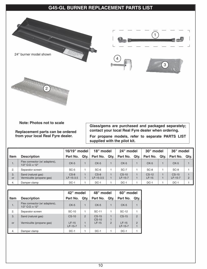
Note: Photos not to scale
Replacement parts can be ordered from your local Real Fyre dealer.
24" burner model shown
16/19" model 18" model 24" model 30" model 36" modelItem Description Part No. Qty. Part No. Qty. Part No. Qty. Part No. Qty. Part No. Qty.
1.Flex connector (w/ adapters),1/2" O.D. x 12"
CK-5 1 CK-5 1 CK-5 1 CK-5 1 CK-5 1
2. Separator screen SC-5 1 SC-6 1 SC-7 1 SC-8 1 SC-9 1
3.or
Sand (natural gas)Vermiculite (propane gas)
CS-8LF-15-3.5
11
CS-8LF-15-3.5
11
CS-10LF-15-7
11
CS-12LF-15
11
CS-15LF-15-7
12
4. Damper clamp DC-1 1 DC-1 1 DC-1 1 DC-1 1 DC-1 1
Glass/gems are purchased and packaged separately; contact your local Real Fyre dealer when ordering.
For propane models, refer to separate PARTS LIST supplied with the pilot kit.
3
1
42" model 48" model 60" modelItem Description Part No. Qty. Part No. Qty. Part No. Qty.
1.Flex connector (w/ adapters),1/2" O.D. x 12"
CK-5 1 CK-5 1 CK-5 1
2. Separator screen SC-10 1 SC-11 1 SC-12 1
3.
or
Sand (natural gas)
Vermiculite (propane gas)
CS-10
LF-15LF-15-7
2
11
CS-15CS-10LF-15
112
CS-15
LF-15LF-15-7
2
21
4. Damper clamp DC-1 1 DC-1 1 DC-1 1
2
4
2
G45-GL BURNER REPLACEMENT PARTS LIST
11
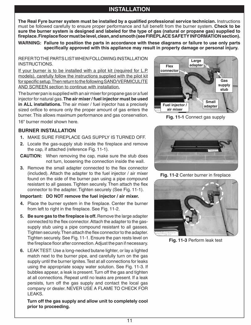
REFER TO THE PARTS LIST WHEN FOLLOWING INSTALLATION INSTRUCTIONS.
If your burner is to be installed with a pilot kit (required for L.P. models), carefully follow the instructions supplied with the pilot kit for specific setup. Then return to the following SAND/VERMICULITE AND SCREEN section to continue with installation.
The burner pan is supplied with an air mixer for propane gas or a fuel injector for natural gas. The air mixer / fuel injector must be used in ALL installations. The air mixer / fuel injector has a precisely sized orifice to ensure only the proper amount of gas enters the burner. This allows maximum performance and gas conservation.
16" burner model shown here.
BURNER INSTALLATION1. MAKE SURE FIREPLACE GAS SUPPLY IS TURNED OFF.
2. Locate the gas-supply stub inside the fireplace and remove the cap, if attached (reference Fig. 11-1).
CAUTION: When removing the cap, make sure the stub does not turn, loosening the connection inside the wall.
3. Remove the small adapter connected to the flex connector (included). Attach the adapter to the fuel injector / air mixer found on the side of the burner pan using a pipe compound resistant to all gasses. Tighten securely. Then attach the flex connector to the adapter. Tighten securely (See Fig. 11-1).
Important: DO NOT remove the fuel injector / air mixer.
4. Place the burner system in the fireplace. Center the burner from left to right in the fireplace. See Fig. 11-2.
5. Be sure gas to the fireplace is off. Remove the large adapter connected to the flex connector. Attach the adapter to the gas-supply stub using a pipe compound resistant to all gasses. Tighten securely. Then attach the flex connector to the adapter. Tighten securely. See Fig. 11-1. Ensure the pan rests level on the fireplace floor after connection. Adjust the pan if necessary.
6. LEAK TEST: Use a long-necked butane lighter, or lay a lighted match next to the burner pipe, and carefully turn on the gas supply until the burner ignites. Test at all connections for leaks using the appropriate soapy water solution. See Fig. 11-3. If bubbles appear, a leak is present. Turn off the gas and tighten at all connections. Repeat until no leaks are present. If a leak persists, turn off the gas supply and contact the local gas company or dealer. NEVER USE A FLAME TO CHECK FOR LEAKS.
Turn off the gas supply and allow unit to completely cool prior to proceeding.
The Real Fyre burner system must be installed by a qualified professional service technician. Instructions must be followed carefully to ensure proper performance and full benefit from the burner system. Check to be sure the burner system is designed and labeled for the type of gas (natural or propane gas) supplied to fireplace. Fireplace floor must be level, clean, and smooth (see FIREPLACE SAFETY INFORMATION section).
WARNING: Failure to position the parts in accordance with these diagrams or failure to use only parts specifically approved with this appliance may result in property damage or personal injury.
INSTALLATION
Fig. 11-2 Center burner in fireplace
Fig. 11-1 Connect gas supply
Large adapter
Gas supply stub
Small adapterFuel injector /
air mixer
Flex connector
Fig. 11-3 Perform leak test
INSTALLATION

12
INSTALLATION (cont.)
Fig. 12-1 Place sand/vermiculite
Fig. 12-2 Place screen
(Pack sand/vermiculite around tubes) Burner pan
Sand/vermiculite up to burner tubes
Separator screen
(If front of screen rises up and does not rest flat, bend it downward as needed)
Separator screen
Burner tubesBurner pan
Sand/vermiculite levelSand/
vermiculite
sloped
Fig. 12-3 Sand/vermiculite & screen detail
Side viewPartially fill pan (only) with sand/vermiculite & slope
front portion of pan.
SAND/VERMICULITE AND SCREEN PLACEMENT
The sand/vermiculite supplied with the unit is specially selected for use with either natural or propane gas. It maximizes flame distribution and provides a cleaner burning flame.
CAUTION: Use only sand for natural gas burners and vermiculite for propane gas burners.
1. Partially fill the burner pan with the sand/vermiculite until it rests at a level toward the top of the burner tubes as shown in Fig. 12-1.
• Pack the sand/vermiculite down around the tubes.
• Slope the sand/vermiculite in the front portion of the pan (see Fig. 12-3).
• Leave space within the pan to allow for screen and glass placement.
• If a pilot kit has been installed, avoid spilling the sand/vermiculite on the pilot assembly. DO NOT place sand/vermiculite on any other parts of the burner, valve, or heat shield.
• Store excess sand/vermiculite in a safe location.
2. Place the separator screen over the sand/vermiculite and pan. The rear of the screen must hook over the rear of the burner pan as shown in Fig. 12-2 and Fig. 12-3. If the front of the screen rises up from the floor of the pan, bend it downward as needed.
Note: The screen must correctly rest onto the burner pan. If it sits too high, remove some of the sand/vermiculite to ensure a proper fit. DO NOT allow for any sand/vermiculite to be above the screen.
Installation continued on next page

13
INSTALLATION (cont.)
IF A PILOT KIT HAS BEEN INSTALLED:KEEP SAND/VERMICULITE, GLASS/GEMS, AND ALL FOREIGN OBJECTS AWAY FROM THE PILOT ASSEMBLY, VALVE ASSEMBLY, AND HEAT SHIELD DURING MEDIA PLACEMENT AND AT ALL TIMES.
GLASS/GEMS PLACEMENTCAUTION: Glass pieces may have sharp edges. Be careful
handling the glass. Use hand protection, such as gloves, if necessary.
Glass/gems MUST be placed to cover the burner (at minimum) for the system to operate properly. Alternatively, glass/gems can be placed to fill the entire fireplace floor. The glass media is purchased and packaged separately. Contact your local Real Fyre dealer for ordering information.
Reference the SPECIFICATIONS section for details on the recommended amounts of media.
1. After the required sand/vermiculite and screen have been placed, pour the glass media (glass, gems) so that the burner pan is covered completely and evenly (see Fig. 13-1).
• Relative to the slope of the burner, DO NOT exceed a 1" depth of glass (directly above the burner pan) as shown in Fig. 13-2. Any additional glass/gems above the burner may cause unsafe operation.
• If a pilot kit has been installed DO NOT place any glass media directly on the pilot assembly, on or within the heatshield, or under a knob if one exists at the front of the valve.
• Store excess glass media in a safe location.
At this stage the burner will function as designed. However, more glass media may be added around the burner for decorative purposes:
2. Complete placement by pouring the remaining glass media on the floor of the fireplace, around the front, rear, and sides of the burner system (see Fig. 13-1).
CAUTION: BURN HAZARD. GLASS AND/OR GEMS ON BURNER SYSTEM WILL REMAIN HOT FOR SOME TIME AFTER USE. You must maintain the placement as shown to ensure proper operation of the burner system. If you need to reposition any media to maintain the proper layout, use heat-resistant gloves or allow media adequate time to cool before handling.
SECONDARY OPTIONSAfter the required sand/vermiculite, screen, and glass/gems have been placed, various river stone, geo shape, and glass nugget options are available. If one of these secondary options are purchased, place them as desired in a decorative pattern on top of the primary media.
Note: These options are not designed to be placed directly on the burner.
Fig. 13-1 Glass media placement
Burner pan
1"
Relative to the slope of the burner, DO NOT exceed a 1" depth of glass (directly
above the burner pan)
Fig. 13-2 Proper media placement
Cover burner (at minimum)
- OR -
Fill entire fireplace (optional)

14
If your burner is operated by a pilot kit, carefully follow the lighting instructions supplied with your pilot kit.
1. STOP! Read the safety information above.
2. Ensure the key valve is completely in the OFF position before beginning lighting sequence.
3. Light a long-stem match or a long-necked butane lighter, and place the flame against the surface of the decorative media near the burner (Fig. 14-1).
4. Once the flame is in position, slowly turn the key valve counter-clockwise toward the ON position until it no longer rotates (see Fig. 14-2). Your burner should light.
WARNING: If the burner does not light within (5) seconds of turning on the key valve, immediately turn the key valve clockwise toward the OFF position until it no longer rotates.
Wait approximately five (5) minutes to clear out any gas, and repeat steps 3-4 above.
If your burner fails to light again, turn the key valve clockwise toward the OFF position until it no longer rotates and contact your dealer or gas supplier.
Note: The flame height can be adjusted via the key valve.
TO SHUT OFF GAS TO THE APPLIANCETo extinguish your gas burner, turn the key valve clockwise toward the OFF position until it no longer rotates (see Fig. 14-2). Be sure the key valve is turned fully off to avoid any gas leakage.
WARNING: IF YOU DO NOT FOLLOW THESE INSTRUCTIONS EXACTLY, A FIRE OR EXPLOSION MAY RESULT, CAUSING PROPERTY DAMAGE, PERSONAL INJURY, OR LOSS OF LIFE.
A. BEFORE LIGHTING, smell all around the unit area for gas. Be sure to smell next to the floor, because some gas is heavier than air and will settle on the floor.
B. WHAT TO DO IF YOU SMELL GAS
1. Shut off the gas to the appliance.
2. Extinguish any open flame.
3. If odor continues, immediately call your gas supplier or the fire department.
C. Use only a proper key to turn the gas line valve. Never use tools. If the valve will not turn, DO NOT try to repair it. Call a qualified professional service technician. Force or attempted repair may result in fire or explosion.
FOR YOUR SAFETY, READ BEFORE LIGHTING
Fig. 14-2
Fig. 14-1
Position flame - then turn on gas
LIGHTING INSTRUCTIONS
Typical application
OFFON
USE, CARE, & SERVICE

15
CLEANING AND SERVICING
Note: Servicing may be necessary to ensure proper operation and burn characteristics.
Always shut off the gas to the appliance while performing service work.
Allow the appliance to cool before servicing.
Installation, service, and repair must be done by an NFI Certified or other qualified professional service technician. The appliance should be examined before use, and must be inspected at least annually to prevent burner shutdown, sooting, odors, etc. It must be checked for clean burning operation with the correct tools to service this unit. More frequent servicing may be required. It is imperative that all components and compartments, burner(s), and circulating air passageways of the appliance be kept clean and free of all obstructions (as applicable).
In addition, a periodic examination and cleaning of the fireplace venting system should be conducted by a qualified professional service technician.
Any safety screen or guard removed for servicing must be replaced prior to operating this appliance.
Verify proper operation after servicing.
If, after a period of use, the flames start to exhibit unusual shapes and behavior, or the burners fail to ignite smoothly, the burner may require cleaning or servicing. If this happens, it is recommended to contact the nearest dealer to get the appliance serviced.
DO NOT remove the rating plates or the warning tags. These are an integral safety and identification component of this appliance.
We recommend following these instructions at the beginning of each fireplace season and as needed throughout the year, depending on your usage pattern and the environmental conditions in your home. More frequent cleaning and maintenance may be necessary when burning propane gas than with natural gas.
FLAME DESCRIPTION
Fig. 15-1 Flame appearance
Observe the flames. The flames should be blue at the base and a combination of blue/yellow at the body and at the tips. The flames should be approximately 8-12" above the glass/gems, with the center flame being the tallest. (See 15-2 for example.)

16
POSSIBLE CAUSE SOLUTIONS
BURNER SHUTTING DOWN DURING OPERATIONA. Insufficient or excessive gas
pressureA1. Check gas pressure (Read D.- F. of IMPORTANT PRE-INSTALLATION AND
FIREPLACE SAFETY INFORMATION section, & check with local gas company).
A2. Other gas appliances may be on the same gas line, dropping gas pressure to the burner. Check pressures with everything operating to ensure adequate pressure.
B. Fireplace too small for unit B. Ensure minimum requirements are met (see SPECIFICATIONS section).
C. Blockages on burner C. Vacuum any lava granules or material that may have fallen onto burner port area.
TROUBLESHOOTING
1
LOW FLAME HEIGHTA. Gas pressure A. Check gas pressure (see Section 1, A1 of this table).
B. Key valve not fully open B. Open key valve fully.
C. Blockage or kink in flex connector kit, plumbing, or burner orifice
C. Clean out blockage. If flex connector is kinked, replace it.
D. Incorrect media (sand or vermiculite) for gas type
D. Contact dealer for proper media (sand or vermiculite).
BURNER NOT BURNING EVENLYA. Burner ports clogged A. Clean burner ports.
B. Media may be packed down too tightly
B. Loosen media around burner pipe by running a flathead screwdriver along both sides of the pipe. Even out media in burner pan.
ODORSA. Gas leak A. Shut off gas, if possible. Follow instructions on front page. Have a qualified
professional installer or the gas company correct all leaks.
B. New home, new carpet, or new paint
B. When these odors are drawn into the fireplace, this may cause objectionable odors. Thoroughly ventilate the area before restarting your burner system.
C. Damper closed C. Ensure that damper is open.
2
3
4

17
FLAME AT AIR MIX / ORIFICE (PROPANE MODELS)A. Burner ports clogged A. Clean burner ports.
B. Gas pressure B. Check gas pressure (see Section 1, A1 of this table).
C. Incorrect media for propane gas and/or media may be packed down too tightly
C. Ensure proper vermiculite media is used with propane gas. Loosen media around burner pipe by running a flathead screwdriver along both sides of the pipe. Even out media in burner pan.
6
SMOKING AND/OR SOOTINGA. Poor draft or downdraft A. Check for chimney blockage. Be sure chimney is at least
3' taller than anything within 10' of it in all directions. If not, consult a chimney sweep. A chimney cap or fan may help.
B. Damper closed B. Ensure that damper is open.
C. Burner is positioned too close to the front of the firebox
C. Move burner system to the center of the firebox.
D. Improper media placement D. See INSTALLATION section for proper media placement.
E. Air mixer on propane set closed (if applicable) E. Open air mixer completely.
F. Air shutters blocked (if applicable) F. Air shutters are blocked with debris. Vacuum debris away from air shutter.
G. Using a product other than Real Fyre glass/gems with burner
G. Make sure only Real Fyre glass/gems are used with your burner.
H. Using natural-gas burner on propane gas or propane gas on natural gas
H. If the gas listed on the nameplate does not match the gas you are burning, shut down the burner system immediately. Then call your dealer.
I. Adding any accessories to burner system I. Shut down burner system and take off any accessories that do not belong with the system.
5
18Robert H. Peterson Co. • 14724 East Proctor Avenue • City of Industry, CA 91746
A COPY OF YOUR SALES SLIP FOR PROOF OF PURCHASE IS REQUIRED
This warranty applies to the original purchaser for products which are installed in the United States or Canada and which are operated and maintained as intended. This warranty is valid only with proof of purchase, commence on the date of purchase, and terminates (both as to original and any replacement products) on the anniversary date of the original purchase of the product per the above schedules.
This warranty covers defects in material and workmanship. This warranty does not cover parts which become defective as a result of negligence, misuse, use not in compliance with the Installation and Owner’s Manual, accidental damage, improper handling, improper storage, improper installation, lack of required routine maintenance (as specified in the Installation and Owner’s Manual), electrical damage, local gas impurities or failure to protect against combustibles. Product must be installed (and gas must be connected) as specified in the Installation and Owner’s Manual by a qualified professional installer. Modifications to products which are not specifically authorized will void this warranty. Accessories, parts, valves, remotes, etc. when used must be Peterson products or this warranty is void. Warrantied items will be repaired or replaced at Peterson’s sole discretion. This warranty does not apply to rust, corrosion, oxidation, or discoloration unless the affected part becomes inoperable.
This warranty does not cover labor or labor related charges, except as provided by separate specific written programs from the Peterson Co. All repair work must be performed by a qualified professional service person and requires prior approval of Peterson.
Peterson may require the defective product or part to be returned to the factory to determine the cause of failure. Peterson will pay freight charges if the product or part is determined to be defective. This warranty does not cover breakage in shipment from our (Independent) distributor to its customer if the damage is determined to have occurred during that shipment.
This warranty specifically excludes liability for indirect, incidental, or consequential damages. Some states and provinces do not allow the exclusion or limitation of incidental or consequential damages, so the above exclusion may not apply to you. This warranty gives you specified legal rights, and you may have other rights that vary from state to state or province.
For additional information regarding this warranty, or to place a warranty claim, contact the R. H. Peterson dealer where the product was purchased.
When contacting your Peterson dealer or the R. H. Peterson Co., please provide the following information:
- Your name, address, telephone number, e-mail- Sales receipt showing where purchased and date purchased- Model number, serial number of product, date code- Relevant information: installer, additions, repairs, when defect was first noted
TO REGISTER YOUR PRODUCT ONLINE GO TO: WWW.RHPETERSON.COM,AND CLICK ON PRODUCT REGISTRATION. THANK YOU FOR YOUR PURCHASE.
PETERSON INDOOR VENTED DECORATIVE GAS APPLIANCELIMITED WARRANTY
Robert H. Peterson Co. ("RHP") warrants your Real Fyre® vented decorative gas appliance to be free from defects in material and workmanship. This warranty is for indoor use only.
Peterson vented ceramic refractory gas logs are warranted for as long as you own them (lifetime).
Peterson vented burner assemblies excluding valves, pilots, and controls are WARRANTED for TEN (10) YEARS.
Peterson glass, gems, nuggets, and fiber-ceramic blend gas logs are warranted for FIVE (5) YEARS.
SPK-26 controls are warranted for THREE (3) YEARS.
APK-17 controls (including -17 valve) are warranted for TWO (2) YEARS.
All other Peterson valves, pilots, and controls are warranted for ONE (1) YEAR (excluding batteries).
WARRANTY