G Model ARTICLE IN PRESS - Repositorio Principal
14
Please cite this article in press as: Sánchez, P., et al., A framework for developing home automation systems: From requirements to code. J. Syst. Software (2011), doi:10.1016/j.jss.2011.01.052 ARTICLE IN PRESS G Model JSS-8657; No. of Pages 14 The Journal of Systems and Software xxx (2011) xxx–xxx Contents lists available at ScienceDirect The Journal of Systems and Software journal homepage: www.elsevier.com/locate/jss A framework for developing home automation systems: From requirements to code Pedro Sánchez ∗ , Manuel Jiménez, Francisca Rosique, Bárbara Álvarez, Andrés Iborra Systems and Electronic Engineering Division (DSIE), Technical University of Cartagena, Campus Muralla del Mar s/n, 30202, Cartagena, Spain article info Article history: Received 28 June 2010 Received in revised form 14 December 2010 Accepted 19 January 2011 Available online xxx Keywords: Home automation Model driven Code generation abstract This article presents an integrated framework for the development of home automation systems following the model-driven approach. By executing model transformations the environment allows developers to generate executable code for specific platforms. The tools presented in this work help developers to model home automation systems by means of a domain specific language which is later transformed into code for home automation specific platforms. These transformations have been defined by means of graph grammars and template engines extended with traceability capabilities. Our framework also allows the models to be reused for different applications since a catalogue of requirements is provided. This framework enables the development of home automation applications with techniques for improving the quality of both the process and the models obtained. In order to evaluate the benefits of the approach, we conducted a survey among developers that used the framework. The analysis of the outcome of this survey shows which conditions should be fulfilled in order to increase reusability. © 2011 Elsevier Inc. All rights reserved. 1. Introduction Rapid advances in electronics, information and communications technology (leading to miniaturization and improvement of per- formance of computers, sensors and networking) have given rise to the development of several home automation (HA) technolo- gies (Chana et al., 2009). HA applications integrate comfort, energy saving, security and communications functions. The aim of an HA system is to provide homes with a certain degree of ‘intelligence’ and to improve the quality of life of its inhabitants. Tasks like auto- matically switching lights and heating, cutting off the supply when gas or water leaks are detected or controlling the home devices remotely from a mobile or a computer through an Internet connec- tion are typical applications of HA domain. There are several HA standards and protocols adopted by the leading companies in the market. Some notable examples are KNX (ISO/IEC14543-3-X and EN50090 standards), Lonworks (ISO/IEC 14908, EN14908 and EIA-709-1 standards) and X10 (a well known international and open industry standard for communica- tion among electronic devices). However, one of the main problems of HA development resides in the fact that there is no consensus in the standard to implement these applications. As stated in Miori et al. (2006), it is improbable that there will be a single dominant technology for HA in short term. Furthermore, each of such stan- ∗ Corresponding author. Tel.: +34 968326460; fax: +34 968325973. E-mail address: [email protected] (P. Sánchez). dards provides its own software suite to create HA applications and program the devices in question. Hence the particular technology (specific platform) must be selected at the initial design stage, as much as the tools and devices to be used depend on this choice. These facts make the development of HA applications strongly plat- form dependent, making it very difficult to raise the abstraction level and work with HA domain concepts rather than technology elements. This drawback can be avoided by adopting the well known Model-Driven Development technique (MDD) (Selic, 2003). In this approach, application code can be automatically generated from platform-independent models. Although MDD techniques have been developed some years ago, there are no well known integrated frameworks for developing HA systems. However, there is currently a need for the creation of tools to develop these systems. These tools should allow the generation of code for several platforms. In this work, we present an integrated framework that allows the definition of HA systems at different levels of abstraction, from requirements to code. Taking advantage of using a domain specific language (DSL) (Mernik et al., 2005) the developer can work with graphical elements and concepts of the HA domain. DSLs provide easy, intuitive domain-specific descriptions of systems using graphical or textual models. A DSL includes the tooling infrastructure for creating and transforming models into executable instances of the language (Kelly and Tolvanen, 2008). In this context, the appearance of the MDD approach has increased the research on these languages as well as new automatic code genera- tion techniques. Nevertheless, the development of DSLs is very time 0164-1212/$ – see front matter © 2011 Elsevier Inc. All rights reserved. doi:10.1016/j.jss.2011.01.052
Transcript of G Model ARTICLE IN PRESS - Repositorio Principal

J
At
PS
a
ARR1AA
KHMC
1
tftgssamgrt
ta(ktotet
0d
ARTICLE IN PRESSG ModelSS-8657; No. of Pages 14
The Journal of Systems and Software xxx (2011) xxx–xxx
Contents lists available at ScienceDirect
The Journal of Systems and Software
journa l homepage: www.e lsev ier .com/ locate / j ss
framework for developing home automation systems: From requirementso code
edro Sánchez ∗, Manuel Jiménez, Francisca Rosique, Bárbara Álvarez, Andrés Iborraystems and Electronic Engineering Division (DSIE), Technical University of Cartagena, Campus Muralla del Mar s/n, 30202, Cartagena, Spain
r t i c l e i n f o
rticle history:eceived 28 June 2010eceived in revised form4 December 2010ccepted 19 January 2011
a b s t r a c t
This article presents an integrated framework for the development of home automation systems followingthe model-driven approach. By executing model transformations the environment allows developers togenerate executable code for specific platforms. The tools presented in this work help developers tomodel home automation systems by means of a domain specific language which is later transformed
vailable online xxx
eywords:ome automationodel driven
ode generation
into code for home automation specific platforms. These transformations have been defined by means ofgraph grammars and template engines extended with traceability capabilities. Our framework also allowsthe models to be reused for different applications since a catalogue of requirements is provided. Thisframework enables the development of home automation applications with techniques for improvingthe quality of both the process and the models obtained. In order to evaluate the benefits of the approach,we conducted a survey among developers that used the framework. The analysis of the outcome of this
ition
survey shows which cond. Introduction
Rapid advances in electronics, information and communicationsechnology (leading to miniaturization and improvement of per-ormance of computers, sensors and networking) have given riseo the development of several home automation (HA) technolo-ies (Chana et al., 2009). HA applications integrate comfort, energyaving, security and communications functions. The aim of an HAystem is to provide homes with a certain degree of ‘intelligence’nd to improve the quality of life of its inhabitants. Tasks like auto-atically switching lights and heating, cutting off the supply when
as or water leaks are detected or controlling the home devicesemotely from a mobile or a computer through an Internet connec-ion are typical applications of HA domain.
There are several HA standards and protocols adopted byhe leading companies in the market. Some notable examplesre KNX (ISO/IEC14543-3-X and EN50090 standards), LonworksISO/IEC 14908, EN14908 and EIA-709-1 standards) and X10 (a wellnown international and open industry standard for communica-ion among electronic devices). However, one of the main problems
Please cite this article in press as: Sánchez, P., et al., A framework for deJ. Syst. Software (2011), doi:10.1016/j.jss.2011.01.052
f HA development resides in the fact that there is no consensus inhe standard to implement these applications. As stated in Miorit al. (2006), it is improbable that there will be a single dominantechnology for HA in short term. Furthermore, each of such stan-
∗ Corresponding author. Tel.: +34 968326460; fax: +34 968325973.E-mail address: [email protected] (P. Sánchez).
164-1212/$ – see front matter © 2011 Elsevier Inc. All rights reserved.oi:10.1016/j.jss.2011.01.052
s should be fulfilled in order to increase reusability.© 2011 Elsevier Inc. All rights reserved.
dards provides its own software suite to create HA applications andprogram the devices in question. Hence the particular technology(specific platform) must be selected at the initial design stage, asmuch as the tools and devices to be used depend on this choice.These facts make the development of HA applications strongly plat-form dependent, making it very difficult to raise the abstractionlevel and work with HA domain concepts rather than technologyelements.
This drawback can be avoided by adopting the well knownModel-Driven Development technique (MDD) (Selic, 2003). In thisapproach, application code can be automatically generated fromplatform-independent models. Although MDD techniques havebeen developed some years ago, there are no well known integratedframeworks for developing HA systems. However, there is currentlya need for the creation of tools to develop these systems. Thesetools should allow the generation of code for several platforms.In this work, we present an integrated framework that allows thedefinition of HA systems at different levels of abstraction, fromrequirements to code. Taking advantage of using a domain specificlanguage (DSL) (Mernik et al., 2005) the developer can work withgraphical elements and concepts of the HA domain.
DSLs provide easy, intuitive domain-specific descriptions ofsystems using graphical or textual models. A DSL includes the
veloping home automation systems: From requirements to code.
tooling infrastructure for creating and transforming models intoexecutable instances of the language (Kelly and Tolvanen, 2008). Inthis context, the appearance of the MDD approach has increased theresearch on these languages as well as new automatic code genera-tion techniques. Nevertheless, the development of DSLs is very time
INJ
2 stems
cbtp
MaeipdsDp
rmeffiaitimn
f
•
•
•
•
d3otcatt
2
2
stfdgrtst
ARTICLEG ModelSS-8657; No. of Pages 14
P. Sánchez et al. / The Journal of Sy
onsuming: ideally, models made using a particular DSL shoulde able to be reused across several implementations to amortizehis effort. The reuse of DSL models across different developmentrojects can help reduce the cost of these projects.
Several works discuss advantages and drawbacks of using DSLs.aintenance, flexibility, productivity, reliability and reusability are
ttributes commonly found in these types of languages (Hermanst al., 2009). With DSLs, reuse is feasible at the model level, makingt possible to reuse partial or entire models, rather than pieces oflatform-dependent code. Thus, the beginning of a new softwareevelopment project can be done from existing reusable assets. Aurprising fact is that reuse hardly plays a significant role in currentSLs as demonstrated in Hermans et al. (2009) for the study of aarticular DSL.
We identify two key aspects that determine the feasibility ofeuse in the context of DSLs: (1) to select a model or a model frag-ent for reuse you must know what is does; and (2) to achieve
ffective reuse, you must be able to discover the model fragmentaster than you could build it. Besides, the use of best practicesor DSL definition and implementation determines the successn model reuse. For instance, language creators usually try tovoid modeling errors by imposing dozens of strongly enforcedntegrity rules that prevent modelers from temporarily breakinghe rules while they are trying to reuse their models. Moreover,nterconnected models should have minimal coupling to improve
odularization and avoid data duplication which lead to mainte-ance and reuse problems.
In short, this article contributes to the state of the art with theollowing features:
A framework that integrates a set of tools for defining HA appli-cations at different levels of abstractions.A set of model transformations (Mens and van Gorp, 2006) thatenables developers to get full executable code.Traceability capabilities (Ramesh and Jarke, 2001) to improvequality both of the process and of the models obtained.A survey that demonstrates the success of reusing models in MDDby means of generic requirements. We investigate factors thatcontribute to this success.
The article is structured as follows: Section 2 deals with intro-ucing the basis of the proposal and the related works. Sectionpresents the proposed framework and also offers a general
verview of the implementation using Eclipse. Section 4 explainshe developed tool for managing traceability. Section 5 gives aost model of the approach. Section 6 details an evaluation of thepproach based on a survey and a comparison of the developedool with two HA commercial tools. Finally, Section 7 is dedicatedo conclusions and future work.
. Foundations and related work
.1. Home automation systems development
At the present time, developers of HA applications mainly useoftware tools provided either by the device manufacturer, inhe case of proprietary system, or by the associations responsibleor providing support for the technology in the case of the stan-ard systems. These tools are usually platform-dependent, code
Please cite this article in press as: Sánchez, P., et al., A framework for deJ. Syst. Software (2011), doi:10.1016/j.jss.2011.01.052
eneration-oriented integrated environments which do little toaise the level of abstraction. Moreover, the concrete syntax thathey use is not usually very intuitive, so that the user requires verypecialized training and can only work in the immediate context ofhe solution.
PRESSand Software xxx (2011) xxx–xxx
The whole process of development of HA applications is carriedout by an expert in the domain who collates the customer’s require-ments for an installation (elements to be integrated, servicesrequired, selection of a concrete technology, etc.) based on his ownexperience. This expert carries out the selection and deploymentof the devices and afterwards programs them (using a platform-dependent development infrastructure) so as to achieve the desiredfunctionality. Working in this manner it is rather difficult to achievesome of the desired attributes of software systems such as inter-operability, flexibility, re-use and productivity. Besides, tools todevelop projects are completely different in each platform, solearning a new technology implies new training. Thus, developersusually focus on a particular technology, leaving aside other plat-forms. This is due to the long training time and high specializationrequired (a good developer would need to have undertaken around100 h of training and have months of practice).
2.2. Related work
2.2.1. MDD for HA developmentThe literature offers a few examples of works which try to
reach in an integrated way the development of HA systems usingan MDD approach. Among these it is important to highlight theworks of Munoz et al. (2006), Voelter and Groher (2007) and Nainet al. (2008) that outline the necessity of using a model drivenapproach in HA systems development. The aim is to increase thelevel of abstraction, the productivity and the quality of the software,besides maintaining the independence of the implementation plat-form. These proposals represent a good example of the advantagesthat the use of MDD offers in the development of HA systems, butthey also present some drawbacks. In the first place, Munoz usesthe UML notation for requirement elicitation which is not very intu-itive for experts in the field of HA. In the work of Voelter, a setof HA devices is defined in the meta-model. Applications are cre-ated using the tool named Tree Editor provided by the plug-in EMFfor Eclipse. Hence to use an HA device not included in the meta-model, it is necessary to build a new meta-model or extend theexisting one. Nain presents EnTiMid as a middleware composed ofseveral layers. A driver layer is in charge of the connection betweenthe devices and the Unified Service layer. A bridge layer links theUnified Service instances to diverse service technologies such asUniversal Plug And Play (UPnP) and Devices Profile for Web Ser-vices (DPWS) (Jammes et al., 2005). The work defines EnTiMid as amiddleware implementation that supports various services accessmodels and also describes how these artifacts are generated usingMDD.
In these proposals the code generation is oriented to obtain OSGi(Open Service Gateway Initiative) drivers for a server or middle-ware platform, and not to the programming of the HA devices.Therefore, it will always be necessary an expert of the specificplatform to program these devices.
Contrary to the previous examples, in our framework the level ofabstraction and usability of requirements modeling rises with theuse of a DSL that uses specific concepts of the domain. In addition,our proposal guides the code generation to the automatic program-ming of the devices of the selected HA technology. In this way theneed for specific knowledge of each platform is avoided, as well asthe intervention of an expert in the technology.
2.2.2. Reuse of DSL modelsThe literature distinguishes between two general types of
veloping home automation systems: From requirements to code.
reuse approaches (von Knethen et al., 2002): composition andgeneration-based approaches. Composition-based approaches arebased on composing reusable assets. This type of approach istypically applied for design or code reuse. Generation-basedapproaches focus on instantiating reusable abstractions. Popular

IN PRESSJ
stems and Software xxx (2011) xxx–xxx 3
e2bp(foqtp
uctsSofadaiStb(
octias
3
ofltpdra
wD
ARTICLEG ModelSS-8657; No. of Pages 14
P. Sánchez et al. / The Journal of Sy
xamples are product-line approaches (Clements and Northrop,002) or patterns (Lam, 1998). For requirements reuse, generation-ased approaches are more popular. A detailed survey aboutroduct line based requirements reuse can be found in Bühne et al.2006). In Jacob and Reed (2000) a summary of general approachesor requirements reusing is given. Others have analyzed the reusef requirements in domains where a set of requirements are fre-uently used (Lam et al., 1997). All these works have in commonhe interest in reuse as a key to improving software developmentroductivity and quality.
Nowadays there is also a considerable interest in evaluating these of DSLs in practice. In DSM (2010), there are some examples andase studies of how the use of DSLs has been applied in many indus-rial applications (mobile applications, business process, embeddedystems, etc.), consistently improving productivity by 10 times.everal authors demonstrate that the use of DSLs raises the levelf abstraction beyond coding and consequently make developmentaster and easier. For example, in Kärnä et al. (2010) an approachpplied to sports instruments and heart rate monitoring devices isescribed. The evaluation of this approach provides an increase oft least 750% in developer productivity, and what is more, a greatmprovement in the quality of the code and development process.ince DSLs are based on the concepts already known and used inhe domain, these constructs are easier to understand and remem-er for all developers, promoting the reuse of validated solutionsKelly and Tolvanen, 2008).
All the previous works concentrate either on requirements reuser in the use of DSLs but none of them analyzes the benefits ofombining both approaches. Furthermore, there is little evidence inhe literature to suggest that requirements reuse is widely practicedn DSL-based proposals. At the same time, the reuse of requirementsnd models in the context of MDD applied to DSLs is also in an initialtage.
. A framework for HA systems development
Fig. 1 shows the main layers and elements involved in the usef the proposed framework for the development of HA systemsollowing the MDD approach. As can be seen, the different MDDevels correspond to: HA requirements, domain specific descrip-ions, UML-based component level, and executable code for specificlatforms. The intermediate UML-based component level allowsevelopers the integration of other types of applications such as
Please cite this article in press as: Sánchez, P., et al., A framework for deJ. Syst. Software (2011), doi:10.1016/j.jss.2011.01.052
obotics and computer vision. Each model is built or obtainedccording to its meta-model by following the MDD paradigm.
Fig. 2 illustrates the steps involved in the use of the frame-ork. The different abstraction levels correspond to requirements,SL (using a predefined catalogue of functional units as detailed
associatedwith
requirementscatalogue
mfra
(
catalogueinspection
fragmentreuse
systemrequirements DS
application modelconstruction
by reuse
Fig. 2. A scheme of th
Fig. 1. Overview of the framework.
at (Jimenej, 2009)), and executable code for specific platforms (inour case, KNX/EIB for deploying HA systems). The correspondencesbetween the requirements and the DSL level are established man-ually. In this way, the partial solutions for each HA requirement arecatalogued. When building a new application, the user may inspectthis catalogue identifying the requirements that are going to beused. By doing this it is possible to reuse the solutions adopted withthe DSL in the development of previous applications. From the DSLlevel towards code generation, the transformations are carried outautomatically. Each model-to-model transformation is registeredin the corresponding traceability model that is later processed by atool that provides the user with a set of reports (as will be describedlater in Section 4).
As demonstrated in Section 6, the existence of a ‘generic’requirements catalogue for subsequent system instantiation cansignificantly contribute to model reuse. Modelers select a subsetof these generic requirements when developing a new system. Foreach generic requirement a model fragment is given using the DSL.A model fragment is part of a complete model in the sense thataccomplishes part of the desired functionality. Then, reuse (seeFig. 3) may be fulfilled by the integration of all the model fragmentsinto the system model to be developed. It is possible that a modelfragment would be syntactically or semantically incomplete. Thus,
veloping home automation systems: From requirements to code.
integrity rules should be disabled temporarily in order to facilitatethe integration of these model fragments.
The following aspects are required in order to achieve aframework with such functionality: (1) to develop graphical user
odelgmentsDSL)
modelrefinement
L model Platform SpecificCode for HA
model to model and model to code
transformations
e methodology.

ARTICLE IN PRESSG ModelJSS-8657; No. of Pages 14
4 P. Sánchez et al. / The Journal of Systems and Software xxx (2011) xxx–xxx
gene
ibhwa
3
cteershsc
aaisrte
Fig. 3. Overview of the approach: from
nterface editors, and (2) to define and implement transformationsetween the defined layers from DSL models to code. All these toolsave been implemented by using the Eclipse development frame-ork. The following subsections give the details of the solutions
dopted in each layer.
.1. Requirements management
In order to integrate requirements management in the MDD pro-ess it is necessary to adopt a meta-model that allows developerso catalogue them. At the present time it is possible to find differ-nt requirements meta-models in the literature (Vicente-Chicotet al., 2007; Molina and Toval, 2009) with different assumptions andelationships. Such meta-models improve requirements reuse anderve as structured requirements reference models. In this work, weave decided to use a basic meta-model that has enough expres-iveness to represent requirements. Fig. 4 shows the class diagramorresponding to the meta-model proposed.
This meta-model is integrated in the development environmentnd it has the level of complexity and sufficient versatility to beble to adopt an approach of requirements reuse. This meta-models valid for other domains and, at the same time, simple in its
Please cite this article in press as: Sánchez, P., et al., A framework for deJ. Syst. Software (2011), doi:10.1016/j.jss.2011.01.052
tructure. Thus, we decided to implement an Eclipse-compliantequirements meta-model editor from scratch in order to facili-ate the integration with the rest of software modules. The rootlement is called Catalogue where a group of requirements (Require-
Fig. 4. Basic requirements meta-model.
ric requirements to integrated models.
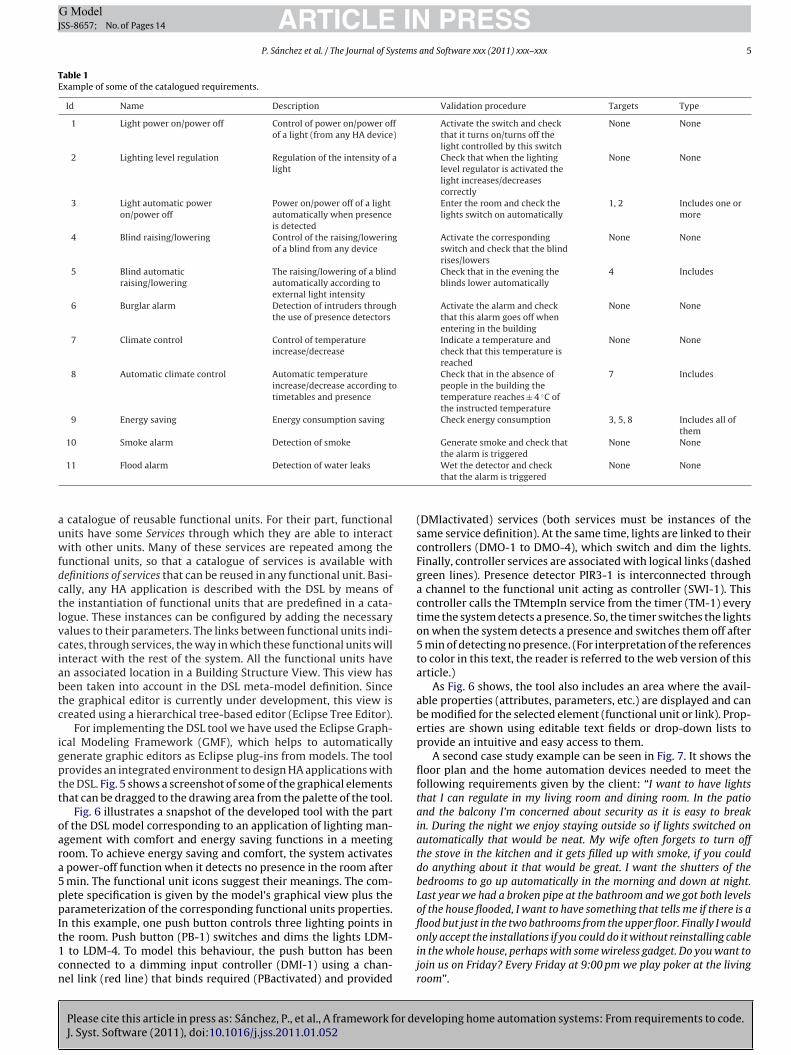
ment) is integrated. Each one of these requirements includes aname, a description and the validation procedure that the usershould adopt to check that the deployed system has the desiredcapability. For example, given the requirement “there should besmoke detection”, the validation procedure would establish “pro-voke a simulated situation with smoke and verify that alarms go on”.The requirements are not isolated, instead they are related to thewhole. To this end the element RelationShip allows the connectionof a requirement (source relationship) with one or more destina-tion requirements (target relationship). The type corresponding tothe relationship among requirements is identified with the ele-ment TypeOfRelationship. Table 1 shows an excerpt of a catalogueof requirements for HA systems keeping in mind the structure ofthis meta-model.
As it can be seen relationships have been considered in the casesof requirements 3, 5, 8 and 9. In some cases the presence of a spe-cific requirement is required (for example, requirement number 5requires number 4), at other times at least one of those indexedis required (as in the case of requirement number 3 with regardto numbers 1 and 2). The relationship can also be of inclusion(see requirement number 9) where in this case the requirementis indicated as being of a greater conceptual level. The relation-ship type among requirements is not closed and depends on theuser. Nevertheless, this factor should be kept in mind because ofthe implications when deriving the specified models with the DSL.The matches between each requirement and fragments of the DSLmodel are traced. By proceeding in this manner, the specificationat the DSL level of a new application starts by reusing model frag-ments. Finally, all the model fragments (reused and new ones) areintegrated into a single model to undergo the successive transfor-mations to code.
3.2. Domain specific descriptions
The framework includes a DSL (see (Jimenej, 2009) for a detaileddescription) for modeling HA systems in a platform-independentway. Such a DSL provides easy and intuitive descriptions of HAsystems using graphical models. Any HA system incorporates anumber of elements (called Functional Units), which are present
veloping home automation systems: From requirements to code.
in all the technologies and standards relevant to the domain. Thesediffer in their architecture and the protocols they use, but they areidentical when it comes to capability. In order to encourage there-use of these functional units and to avoid having to repeatedlydefine the same unit for each application, it was decided to use
ARTICLE IN PRESSG ModelJSS-8657; No. of Pages 14
P. Sánchez et al. / The Journal of Systems and Software xxx (2011) xxx–xxx 5
Table 1Example of some of the catalogued requirements.
Id Name Description Validation procedure Targets Type
1 Light power on/power off Control of power on/power offof a light (from any HA device)
Activate the switch and checkthat it turns on/turns off thelight controlled by this switch
None None
2 Lighting level regulation Regulation of the intensity of alight
Check that when the lightinglevel regulator is activated thelight increases/decreasescorrectly
None None
3 Light automatic poweron/power off
Power on/power off of a lightautomatically when presenceis detected
Enter the room and check thelights switch on automatically
1, 2 Includes one ormore
4 Blind raising/lowering Control of the raising/loweringof a blind from any device
Activate the correspondingswitch and check that the blindrises/lowers
None None
5 Blind automaticraising/lowering
The raising/lowering of a blindautomatically according toexternal light intensity
Check that in the evening theblinds lower automatically
4 Includes
6 Burglar alarm Detection of intruders throughthe use of presence detectors
Activate the alarm and checkthat this alarm goes off whenentering in the building
None None
7 Climate control Control of temperatureincrease/decrease
Indicate a temperature andcheck that this temperature isreached
None None
8 Automatic climate control Automatic temperatureincrease/decrease according totimetables and presence
Check that in the absence ofpeople in the building thetemperature reaches ± 4 ◦C ofthe instructed temperature
7 Includes
9 Energy saving Energy consumption saving Check energy consumption 3, 5, 8 Includes all ofthem
10 Smoke alarm Detection of smoke Generate smoke and check that None None
auwfdctlvciabtc
igptt
oara5ppIt1cn
11 Flood alarm Detection of water leaks
catalogue of reusable functional units. For their part, functionalnits have some Services through which they are able to interactith other units. Many of these services are repeated among the
unctional units, so that a catalogue of services is available withefinitions of services that can be reused in any functional unit. Basi-ally, any HA application is described with the DSL by means ofhe instantiation of functional units that are predefined in a cata-ogue. These instances can be configured by adding the necessaryalues to their parameters. The links between functional units indi-ates, through services, the way in which these functional units willnteract with the rest of the system. All the functional units haven associated location in a Building Structure View. This view haseen taken into account in the DSL meta-model definition. Sincehe graphical editor is currently under development, this view isreated using a hierarchical tree-based editor (Eclipse Tree Editor).
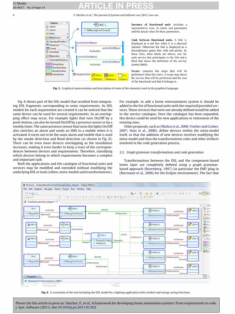
For implementing the DSL tool we have used the Eclipse Graph-cal Modeling Framework (GMF), which helps to automaticallyenerate graphic editors as Eclipse plug-ins from models. The toolrovides an integrated environment to design HA applications withhe DSL. Fig. 5 shows a screenshot of some of the graphical elementshat can be dragged to the drawing area from the palette of the tool.
Fig. 6 illustrates a snapshot of the developed tool with the partf the DSL model corresponding to an application of lighting man-gement with comfort and energy saving functions in a meetingoom. To achieve energy saving and comfort, the system activatespower-off function when it detects no presence in the room aftermin. The functional unit icons suggest their meanings. The com-lete specification is given by the model’s graphical view plus thearameterization of the corresponding functional units properties.
Please cite this article in press as: Sánchez, P., et al., A framework for deJ. Syst. Software (2011), doi:10.1016/j.jss.2011.01.052
n this example, one push button controls three lighting points inhe room. Push button (PB-1) switches and dims the lights LDM-
to LDM-4. To model this behaviour, the push button has beenonnected to a dimming input controller (DMI-1) using a chan-el link (red line) that binds required (PBactivated) and provided
the alarm is triggeredWet the detector and checkthat the alarm is triggered
None None
(DMIactivated) services (both services must be instances of thesame service definition). At the same time, lights are linked to theircontrollers (DMO-1 to DMO-4), which switch and dim the lights.Finally, controller services are associated with logical links (dashedgreen lines). Presence detector PIR3-1 is interconnected througha channel to the functional unit acting as controller (SWI-1). Thiscontroller calls the TMtempIn service from the timer (TM-1) everytime the system detects a presence. So, the timer switches the lightson when the system detects a presence and switches them off after5 min of detecting no presence. (For interpretation of the referencesto color in this text, the reader is referred to the web version of thisarticle.)
As Fig. 6 shows, the tool also includes an area where the avail-able properties (attributes, parameters, etc.) are displayed and canbe modified for the selected element (functional unit or link). Prop-erties are shown using editable text fields or drop-down lists toprovide an intuitive and easy access to them.
A second case study example can be seen in Fig. 7. It shows thefloor plan and the home automation devices needed to meet thefollowing requirements given by the client: “I want to have lightsthat I can regulate in my living room and dining room. In the patioand the balcony I’m concerned about security as it is easy to breakin. During the night we enjoy staying outside so if lights switched onautomatically that would be neat. My wife often forgets to turn offthe stove in the kitchen and it gets filled up with smoke, if you coulddo anything about it that would be great. I want the shutters of thebedrooms to go up automatically in the morning and down at night.Last year we had a broken pipe at the bathroom and we got both levelsof the house flooded, I want to have something that tells me if there is a
veloping home automation systems: From requirements to code.
flood but just in the two bathrooms from the upper floor. Finally I wouldonly accept the installations if you could do it without reinstalling cablein the whole house, perhaps with some wireless gadget. Do you want tojoin us on Friday? Every Friday at 9:00 pm we play poker at the livingroom”.
ARTICLE IN PRESSG ModelJSS-8657; No. of Pages 14
6 P. Sánchez et al. / The Journal of Systems and Software xxx (2011) xxx–xxx
f som
imsppwaabTidwa
su
Fig. 5. Graphical representation and description o
Fig. 8 shows part of the DSL model that resulted from integrat-ng DSL fragments corresponding to some requirements. As DSL
odels for each requirement are created it can be noticed that theame device can be used for several requirements. So an overlap-ing effect may occur. For example lights that turn On/Off by aush-button, can also be turned On/Off by a presence sensor or by aeekly timer. The same presence sensor that turns the lights On/Off
lso switches an alarm and sends an SMS to a mobile when it isctivated. It turns out to be the same alarm and mobile that is usedy the smoke detection and flood detection (as shown in Fig. 8).here can be even more devices overlapping as the installationncreases, making it even harder to keep a trace of the correspon-ences between devices and requirements. Therefore, classifying
Please cite this article in press as: Sánchez, P., et al., A framework for deJ. Syst. Software (2011), doi:10.1016/j.jss.2011.01.052
hich devices belong to which requirements becomes a complexnd important task.
Both the applications and the catalogue of functional units andervices may be modified and extended without modifying thenderlying DSL or tools (editor, meta-models and transformations).
Fig. 6. A screenshot of the tool including the DSL model for a ligh
e of the elements used in the graphical language.
For example, to add a home entertainment system it should beadded to the list of functional units with the required/provided ser-vices. Those services that were not already defined would be addedto the service catalogue. Once the catalogue has been expanded,this device could be used for new applications or extensions of theexisting ones.
Other proposals, such as (Munoz et al., 2006; Voelter and Groher,2007; Nain et al., 2008), define devices within the meta-modelitself, so that the addition of new devices involves modifying themeta-model and thus the transformations rules and other artifactsinvolved in the code generation process.
3.3. Graph grammar transformations and code generation
veloping home automation systems: From requirements to code.
Transformations between the DSL and the component-basedlower layer are completely defined using a graph grammar-based approach (Rozenberg, 1997) (in particular the EMT plug-in(Biermann et al., 2006) for the Eclipse environment). The fact that
ting application with comfort and energy saving functions.

ARTICLE IN PRESSG ModelJSS-8657; No. of Pages 14
P. Sánchez et al. / The Journal of Systems and Software xxx (2011) xxx–xxx 7
t and a
mmtane
Fig. 7. House plan with devices included in i
odels are usually represented by graphs makes a graph grammarore attractive than other approaches; for instance, transforma-
Please cite this article in press as: Sánchez, P., et al., A framework for deJ. Syst. Software (2011), doi:10.1016/j.jss.2011.01.052
ion rules expressed by means of graphs are easier to understandnd trace. The overall conversion from the DSL to the compo-ent model uses several transformations. Each transformation isxpressed with rules with a left hand side (LHS), representing
Fig. 8. DSL fragments for various requirements
descriptive table of the considered devices.
the pre-conditions for the transformation, and a right hand side(RHS), showing the result of the transformation. Both the LHS and
veloping home automation systems: From requirements to code.
RHS are graphs, both of which usually contain elements from boththe input and output models. The inclusion of elements from theoutput model in the LHS ensures that the transformations are exe-cuted in the correct sequence. A rule may also have a Boolean
needed within the previous application.
ARTICLE IN PRESSG ModelJSS-8657; No. of Pages 14
8 P. Sánchez et al. / The Journal of Systems and Software xxx (2011) xxx–xxx
F l. Blaca n of tho
nfitfmg
spHbDiioc
cssp
ig. 9. Example of graph transformation rule: from DSL to component model levepplication view (DSL) instance; orange: transformation instance. (For interpretatiof the article.)
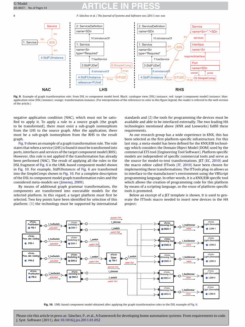
egative application condition (NAC), which must not be satis-ed to apply it. To apply a rule to a source graph (the grapho be transformed), there must exist a sub-graph isomorphismrom the LHS to the source graph. After the application, there
ust be a sub-graph isomorphism from the RHS to the resultraph.
Fig. 9 shows an example of a graph transformation rule. The ruletates that when a service (LHS) is found it must be transformed intoorts, interfaces and services of the target component model (RHS).owever, this rule is not applied if the transformation has alreadyeen performed (NAC). The result of applying all the rules to theSL fragment of Fig. 6 is the UML-based component model shown
n Fig. 10. For example, StdFUInstances of Fig. 6 are transformednto the SimpleComps shown in Fig. 10. For a complete descriptionf the DSL to component model graph transformation rules and theonsidered meta-models see (Jimenej, 2009).
By means of additional graph grammar transformations, the
Please cite this article in press as: Sánchez, P., et al., A framework for deJ. Syst. Software (2011), doi:10.1016/j.jss.2011.01.052
omponents are transformed into executable models for theelected platform. In this regard, a target platform must first beelected. Two key points have been identified for selection of thislatform: (1) the technology must be supported by international
Fig. 10. UML-based component model obtained after applying th
k: catalogue view (DSL) instance; red: target (component model) instance; blue:e references to color in this figure legend, the reader is referred to the web version
standards and (2) the tools for programming the devices must beavailable and able to be interfaced externally. The two leading HAtechnologies mentioned above (KNX and Lonworks) fulfill theserequirements.
As our research group has a wide experience in KNX, this hasbeen selected as the first platform-specific infrastructure. For thislast step, a meta-model has been defined for the KNX/EIB technol-ogy which considers the Domain Object Model (DOM) used by thecommercial ETS tool (Engineering Tool Software). Platform specificmodels are independent of specific commercial tools and serve asthe source for model-to-text transformations. JET (EC, 2010) andthe macro editor called ITTools (IT, 2010) have been chosen forimplementing these transformations. The ITTools plug-in allows usto interface to the manufacturer’s environment using the VBScriptprogramming language. In other words, it is a KNX/EIB specific toolwhich allows the creation of programming code for this platformby means of a scripting language, so the reuse of platform-specific
veloping home automation systems: From requirements to code.
tools is promoted.Below an excerpt of a JET template is shown. It is used to gen-
erate the ITTools macro needed to insert new devices in the HAproject:
e graph transformation rules to the DSL example of Fig. 6.
ARTICLE IN PRESSG ModelJSS-8657; No. of Pages 14
P. Sánchez et al. / The Journal of Systems and Software xxx (2011) xxx–xxx 9
n of th
<
<
A
<
A
<
A
<
A
<
A
<
A
A
S
.
fUmd‘
A
A
A
A
A
A
A
S
.‘
.‘
.‘
p
Fig. 11. ETS Project obtained after executio
c:iterate select = ‘‘$d’’ var = ‘‘device’’>
c:if test = ‘‘$device/@name’’>
ddDevice RefName = < c:get select = ‘‘$device/@name’’/>
/c:if>
ddDevice RefName = LCase(AddDevice RefName)
c:if test = ‘‘$device/@manufacturer’’>
ddDevice Manufacturer = < c:get select = ‘‘$device/@manufacturer’’/>
/c:if>
ddDevice Manufacturer = LCase(AddDevice Manufacturer)
c:if test = ‘‘$device/@physicalA’’>
ddDevice PhysicalAddress = < c:get select = ‘‘$device/@physicalA’’/>
/c:if>
ddDevice AuxAlreadyAdded = false
ddDevice AuxName = ‘‘new device’’ + AddDevice RefName
et AddDevice auxDR = Project.parent
. .
This template generates a VBScript macro to create a new deviceor each of the devices present in the KNX model (obtained from theML-based component model of Fig. 10). The listing of the obtainedacro would look at follows (JET tags have been replaced with KNX
evice-specific information):Macro for inserting device 1’
ddDevice RefName = ‘‘Universal Dimming Actuator 1-gang REG’’
ddDevice RefName = LCase(AddDevice RefName)
ddDevice Manufacturer = ‘‘Abrecth Jung’’
ddDevice Manufacturer = LCase(AddDevice Manufacturer)
ddDevice PhysicalAddress = ‘‘1.1.2’’
ddDevice AuxAlreadyAdded = false
ddDevice AuxName = ‘‘new device’’ + AddDevice RefName
et AddDevice auxDR = Project.parent
. .Macro for inserting device 2’
. .
Please cite this article in press as: Sánchez, P., et al., A framework for deJ. Syst. Software (2011), doi:10.1016/j.jss.2011.01.052
Macro for inserting device n’
. .More macros for binding, parametrization, etc.’
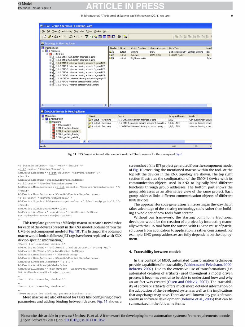
More macros are also obtained for tasks like configuring devicearameters and adding binding between devices. Fig. 11 shows a
e ITTools macros for the example of Fig. 6.
screenshot of the ETS project generated from the component modelof Fig. 10 executing the mentioned macros within the tool. At thetop left the devices in the KNX topology are shown. The top rightsection illustrates the configuration of the DMO-1 device with itscommunication objects, used in KNX to logically bind differentfunctions through group addresses. The bottom part shows thegroup addresses as an alternative view of the same project. Eachgroup address links different communication objects of differentKNX devices.
This approach for code generation is interesting in the way that ittakes advantage of the existing technology tools rather than build-ing a whole set of new tools from scratch.
Without our framework, the starting point for a traditionaldeveloper would be the creation of a project by interacting manu-ally with the ETS tool from the outset. With ETS the reuse of partialsolutions from application to application is rather constrained. Forexample, KNX group addresses are fully dependent on the deploy-ment.
4. Traceability between models
In the context of MDD, automated transformation techniquesprovide capabilities for traceability (Valderas and Pelechano, 2009;Behrens, 2007). Due to the extensive use of transformations (i.e.automated creation of artifacts) used throughout a model drivenprocess it becomes central to be able to understand how and whyan artifact was created (Olsen and Oldevik, 2007). The traceabil-
veloping home automation systems: From requirements to code.
ity of software artifacts offers much more detailed information onthe adaptation of the developed system as well as the implicationsthat any change may have. There are well known key goals of trace-ability in software development (Kolovos et al., 2006) that can besummarized in the following items:
ARTICLE ING ModelJSS-8657; No. of Pages 14
10 P. Sánchez et al. / The Journal of Systems
1
2
3
tdaedoamfse
4
eeOor(tM
Fil
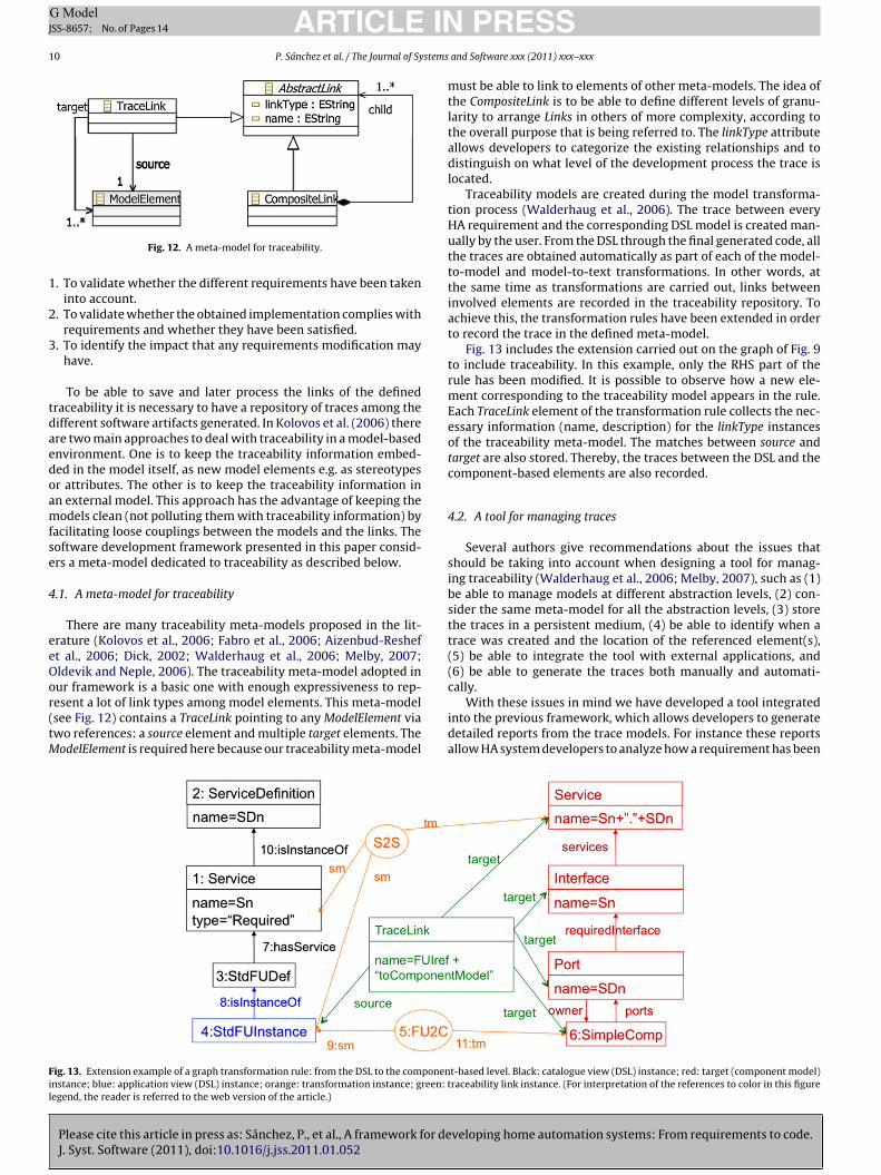
Fig. 12. A meta-model for traceability.
. To validate whether the different requirements have been takeninto account.
. To validate whether the obtained implementation complies withrequirements and whether they have been satisfied.
. To identify the impact that any requirements modification mayhave.
To be able to save and later process the links of the definedraceability it is necessary to have a repository of traces among theifferent software artifacts generated. In Kolovos et al. (2006) therere two main approaches to deal with traceability in a model-basednvironment. One is to keep the traceability information embed-ed in the model itself, as new model elements e.g. as stereotypesr attributes. The other is to keep the traceability information inn external model. This approach has the advantage of keeping theodels clean (not polluting them with traceability information) by
acilitating loose couplings between the models and the links. Theoftware development framework presented in this paper consid-rs a meta-model dedicated to traceability as described below.
.1. A meta-model for traceability
There are many traceability meta-models proposed in the lit-rature (Kolovos et al., 2006; Fabro et al., 2006; Aizenbud-Resheft al., 2006; Dick, 2002; Walderhaug et al., 2006; Melby, 2007;ldevik and Neple, 2006). The traceability meta-model adopted in
Please cite this article in press as: Sánchez, P., et al., A framework for deJ. Syst. Software (2011), doi:10.1016/j.jss.2011.01.052
ur framework is a basic one with enough expressiveness to rep-esent a lot of link types among model elements. This meta-modelsee Fig. 12) contains a TraceLink pointing to any ModelElement viawo references: a source element and multiple target elements. TheodelElement is required here because our traceability meta-model
ig. 13. Extension example of a graph transformation rule: from the DSL to the componennstance; blue: application view (DSL) instance; orange: transformation instance; green:egend, the reader is referred to the web version of the article.)
PRESSand Software xxx (2011) xxx–xxx
must be able to link to elements of other meta-models. The idea ofthe CompositeLink is to be able to define different levels of granu-larity to arrange Links in others of more complexity, according tothe overall purpose that is being referred to. The linkType attributeallows developers to categorize the existing relationships and todistinguish on what level of the development process the trace islocated.
Traceability models are created during the model transforma-tion process (Walderhaug et al., 2006). The trace between everyHA requirement and the corresponding DSL model is created man-ually by the user. From the DSL through the final generated code, allthe traces are obtained automatically as part of each of the model-to-model and model-to-text transformations. In other words, atthe same time as transformations are carried out, links betweeninvolved elements are recorded in the traceability repository. Toachieve this, the transformation rules have been extended in orderto record the trace in the defined meta-model.
Fig. 13 includes the extension carried out on the graph of Fig. 9to include traceability. In this example, only the RHS part of therule has been modified. It is possible to observe how a new ele-ment corresponding to the traceability model appears in the rule.Each TraceLink element of the transformation rule collects the nec-essary information (name, description) for the linkType instancesof the traceability meta-model. The matches between source andtarget are also stored. Thereby, the traces between the DSL and thecomponent-based elements are also recorded.
4.2. A tool for managing traces
Several authors give recommendations about the issues thatshould be taking into account when designing a tool for manag-ing traceability (Walderhaug et al., 2006; Melby, 2007), such as (1)be able to manage models at different abstraction levels, (2) con-sider the same meta-model for all the abstraction levels, (3) storethe traces in a persistent medium, (4) be able to identify when atrace was created and the location of the referenced element(s),(5) be able to integrate the tool with external applications, and(6) be able to generate the traces both manually and automati-
veloping home automation systems: From requirements to code.
cally.With these issues in mind we have developed a tool integrated
into the previous framework, which allows developers to generatedetailed reports from the trace models. For instance these reportsallow HA system developers to analyze how a requirement has been
t-based level. Black: catalogue view (DSL) instance; red: target (component model)traceability link instance. (For interpretation of the references to color in this figure

ARTICLE IN PRESSG ModelJSS-8657; No. of Pages 14
P. Sánchez et al. / The Journal of Systems and Software xxx (2011) xxx–xxx 11
from
tw
igoitc2o
dwlh
4
obi
1
Fig. 14. Traceability report created by the tool:
aken into account in the process of automatic code generation asell as including information on the solution adopted.
Fig. 14 shows a screen capture of the use of our tool for traceabil-ty. For each one of the traces details of name and description areiven, as well as the relative information to the source and the targetf the traced elements. The first row of the report shows a Compos-
teLink that arranges all the information related to Links involved inhe solution using the DSL for the illumination requirement. In thisase, Links represent the traces between the requirements numberand 3 of Table 1, which have associated as targets the elements
f the DSL (functional units and links among them).As explained below, the traceability report allows the user to
istinguish which requirements have been taken into account,hich architectural elements give support to each one of them, and
astly, in which physical devices of the platform the requirementsave been implemented.
.3. Benefits derived from traceability
In this subsection, we examine the main benefits that arebtained by using the traceability reports introduced above. Theseenefits are derived from the possibility of performing the follow-
ng tasks:
. To validate whether all the requirements have been supported. Thisvalidation can be carried out through the traceability reports. Inthe first place, we can check that all the requirements are rep-resented by means of the model elements obtained according tothe DSL. During the process of checking that a requirement hasbeen taken into account, we can filter the traceability report tofind those DSL elements that are linked to the analyzed require-
Please cite this article in press as: Sánchez, P., et al., A framework for deJ. Syst. Software (2011), doi:10.1016/j.jss.2011.01.052
ment. For example, the requirement number 3 (Table 1) thatrepresents the control of the automatic lighting in relation to thepresence of people implies the presence of a functional unit forpresence detection (PIR3-2) and of a controller for the power offtimer. The analyst can check, according to the traceability report
requirements to domain specific descriptions.
whether the elements of presence detection and timer are partof the solution of this requirement.
2. To verify whether the DSL model is compliant with the homeautomation requirements. To do this the DSL elements shouldbe validated to see if they fit with the semantics of the rel-evant requirements. In this case, the traceability report helpsthe analyst to know which HA requirements have given riseto which elements of the DSL model. To be able to carry outthis validation, the analyst should have the templates used inthe implementation of the transformation rules perfectly cat-alogued. The traceability report is required for the verificationof the requirements. However, the verification of the correc-tion is not immediate. In the case of the requirement number3 (Table 1), to assure the correctness of the model implies cor-rectly characterizing the parameterization of the controller forthe timer and to verify that its switching off service is correctlylinked to the switching services of the lighting elements. Thesefeatures can be verified more easily with the trace informationprovided by the traceability tool.
3. To establish the impact of changing a home automation require-ment. It is usual that the users of the system suggest changes tothe requirements throughout the whole development process.The traceability report can help analysts to evaluate the impactof these changes before applying them. The first useful fact forthe analyst is to know how many DSL elements, how many archi-tectural components, and how many elements of the specificlevel of the execution platform should be modified. This impactstudy is very important because it allows the analyst to obtainan integrated vision of the changes that should be kept in mindwhen changing a requirement. On the other hand, the analyst canjust as easily verify the implications that modifying a require-
veloping home automation systems: From requirements to code.
ment of this type has in relation to the rest of the requirementsalready implanted. For example, they could modify the require-ment number 3 (Table 1) to include an additional condition ofswitching the light on when the light entering from the exte-rior was insufficient. The inclusion of this modification would
IN PRESSJ
1 stems and Software xxx (2011) xxx–xxx
5
momtatmtdD
C
wu
(etd
C
trCmffitsadmii
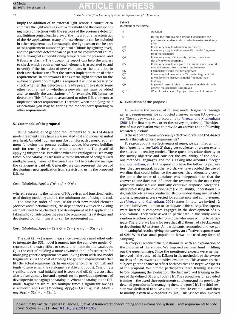
Table 2Questions of the survey.
# Question
Q1 During the third training session I looked into theplatform-dependent code in order to customize it veryoften
Q2 It was very easy to add new requirementsQ3 It was very easy to define a new DSL model fragment
from requirementsQ4 It was very easy of to identify, define, connect and
classify new requirementsQ5 It was very easy to integrate in a unique model several
model fragments from distinct requirementsQ6 I gained time using the new approachQ7 It was easy to know what a DSL model fragment didQ8 It was faster to discover a model fragment than
ARTICLEG ModelSS-8657; No. of Pages 14
2 P. Sánchez et al. / The Journal of Sy
imply the addition of an external light sensor, a controller tocompare the light readings with a threshold and the correspond-ing interconnections with the services of the presence detectorand lighting controllers. In view of the integration characteristicsof the HA applications, many of these elements can be includedin other requirements. For example, the light sensor can be partof the requirement number 5 (control of blinds by lighting level),and the presence detector can be part of the requirements num-ber 8 (change of air conditioning temperature for presence) and6 (burglar alarm). The traceability report can help the analystto check which requirement each element is associated to andto verify if the inclusion of new elements or the alteration intheir associations can affect the correct implementation of otherrequirements. In other words, if an external light detector for theautomatic power on of lights is required it will be necessary to:check whether this detector is already present to satisfy someother requirement or whether a new element must be addedand, to modify the associations of, for example, PIR (presencedetection). This PIR can be associated to other DSL elements toimplement other requirements. Therefore, when modifying theirassociations you may be altering the models corresponding toother requirements.
. Cost model of the proposal
Using catalogues of generic requirements to reuse DSL-basedodel fragments may have an associated cost and incurs an initial
verhead. A model fragment must be built for each generic require-ent following the process outlined above. Moreover, building
ools for reusing these requirements takes time. The payoff ofpplying this proposal is realized when the catalogue is used manyimes. Since catalogues are built with the intention of being reused
ultiple times, in most of the cases the effort to create and managehe catalogue is paid off. Generally, we can represent the cost ofeveloping a new application from scratch and using the proposedSL as:
ost (Modeling App) = f (n2 + c) ≈ O(n2),
here n represents the number of HA devices and functional unitssed during modeling and c is the minimum cost of using the tool.
The cost has order n2 because for each new model elementdevices and functional units), the dependencies with each existinglement need to be checked. The development of HA applicationsaking into consideration the reusable requirements catalogue andeveloped tool for integration can be represented as:
ost (Modeling AppR) = C1 + C2 + C3 + f (n + c) ≈ O(n + c).
The cost O(n + c) is now linear since developers need effort onlyo integrate the DSL model fragment into the complete model. C1epresents the extra effort to create and maintain the catalogue.2 is the cost of building a more advanced tool infrastructure foranaging generic requirements and linking them with DSL model
ragments. C3 is the cost of finding the generic requirements thatts the actual requirements. In our experience, C1 is not high andends to zero when the catalogue is stable and robust. C2 is only aignificant overhead initially and is soon paid off. C3 is a cost that
Please cite this article in press as: Sánchez, P., et al., A framework for deJ. Syst. Software (2011), doi:10.1016/j.jss.2011.01.052
lso is also typically low and depends on the previous experience ofevelopers in managing the catalogue. When the catalogue and DSLodel fragments are reused multiple times a significant savings
s achieved and Cost (Modeling AppR) ≈ O(n + c) � Cost (Model-ng App) ≈ O(n2 + c) ≈ O(n2).
building itQ9 In general terms, I think that reuse of models through
generic requirements is improvedQ10 When I start a new HA project, how would I proceed?
6. Evaluation of the proposal
To measure the success of reusing model fragments throughgeneric requirements we conducted a survey among HA develop-ers. The survey was set up according to Pfleeger and Kitchenham(2001). The first step was to set the survey objective(s). The objec-tive of our evaluation was to provide an answer to the followingresearch question:
Is the use of the framework really effective for reusing DSL-basedmodels through generic requirements?
To reason about the effectiveness of reuse, we identified a num-ber of questions (see Table 2) that gives to a lesser or greater extentthe success in reusing models. These questions relate directly tothe survey objective and consider the availability of the previ-ous methods, languages, and tools. Taking into account (Pfleegerand Kitchenham, 2001), the questions have the following proper-ties: they are neutral, in other words, we have avoided the use ofwording that could influence the answer; they adequately coverthe topic; the order of questions was independent so that theanswer to one does not influence the response to the next; theyrepresent unbiased and mutually exclusive response categories.After pre-testing the questionnaire (i.e. reliability, understandabil-ity, validity, etc.) it was conducted. Before undertaking any detailedanalysis, responses were vetted for consistency and completenessas (Pfleeger and Kitchenham, 2001) states. In total we invited 12experts in HA development to participate in this survey. The expertswere located in companies engaged in the development of HAapplications. They were asked to participate in the study and arandom selection was made from those who were willing to partic-ipate. Therefore, we knew for sure that all of them had a backgroundin developing HA systems. All participants responded and we got11 meaningful results, giving our survey an effective response rateof 92%. With that small population it was not used any form ofsampling.
Developers received the questionnaire with an explanation ofthe purpose of the survey. We imposed no time limit in fillingout the questionnaire. Since the mentioned experts were neitherinvolved in the design of the DSL nor in the methodology there wereno risks of bias towards a positive evaluation. This assures us thatsubjects got the chance to reflect both positive and negative aspectsof the proposal. We offered participants three training sessionsbefore beginning the evaluation. The first involved training in the
veloping home automation systems: From requirements to code.
use of the defined DSL and tools (3 h). The second session providedtraining in the use of the requirements catalogue and the previouslydetailed procedures for managing the catalogue (2 h). The third ses-sion was dedicated to solve a medium-size HA example and thento modify it with new capabilities (4 h). This last session involved

ARTICLE IN PRESSG ModelJSS-8657; No. of Pages 14
P. Sánchez et al. / The Journal of Systems and Software xxx (2011) xxx–xxx 13
Table 3Outcomes of the developed survey.
# Strongly disagree Disagree Neutral Agree Strongly agree
Q1 3 5 2 1 0Q2 0 1 2 5 3Q3 0 1 3 6 1Q4 0 1 2 5 3Q5 1 3 4 2 1Q6 0 1 2 4 4Q7 0 2 3 4 2Q8 0 1 2 6 2Q9 0 1 2 5 3
om sc
sne
gfqpnidrwwcottpitittpvD
ksr
TC
# Use the catalogue and DSL fragments Start a new DSL model fr
Q10 6 3
cenarios where all the situations were simulated (new categories,ew devices, new requirements, new requirements relationships,tc.).
As Table 3 shows, the outcomes of the study indicate that in theiven survey the framework helped to improve reuse, and there-ore, to reduce time and costs. The distribution of the answers touestion number 1 demonstrates the confidence that commerciallatform-dependent developers have in the tool. It also shows theeed for long-term experiences that provide greater confidence
n the proposed approach. The responses to question 2 show theifficulties encountered by some users in the management of theequirements catalogue. We think that most of these difficultiesere due to the fact that these users were not familiar with theay in which the requirements were organized. Again, deficien-
ies related to this aspect would diminish with the continued usef the catalogue. Questions 3 and 7 demonstrate the capabilitieshat our tool provides for the integration and interpretation ofhe DSL fragments in the catalogue, one of the main goals of ourroposal. Question number 5 highlights the extra effort needed to
ntegrate model fragments. The answers to questions 6 and 8 showhat time is gained using our tool. We believe that performancemprovements can be even more significant as both the tool andhe developers’ training evolve. Question number 10 is relevant inhis study because it reflects the improvement in the developmentrocess. Moreover, question number 9 summarizes the favorableiew of developers about the proposal regarding requirements andSL fragments reuse.
Please cite this article in press as: Sánchez, P., et al., A framework for deJ. Syst. Software (2011), doi:10.1016/j.jss.2011.01.052
Table 4 summarizes a comparison of our tool with two HA wellnown commercial tools based in our experience. As it can beeen, the results highlight the interest to continue working on theesearch line proposed in this paper.
able 4omparison of features of the developed tool and the two leading HA technology-depend
Feature Developed tool
Concepts used by the tool user Exclusively HA domainconcepts
Requirement support YesGraphical syntax for HA
conceptsYes
Platform independentmodeling
Yes
Design reuse Very easyCapability of integrating
different HA technologiesYes (through future extensionsin transformations)
Possibility of integrating otherdomains (wireless sensornetworks, computer vision,robotics, etc.)
Yes (by means of the platformindependent componentmodel)
Traceability support Yes
ratch Copy-modify previous models Use platform-dependent tools
2 0
7. Conclusions and future work
In this work we have introduced a framework for developingHA systems by following a model driven approach. The develop-ment of this kind of systems is a time-consuming endeavor thatcould only be afforded by experienced developers with program-ming and execution-platform expertise. Our framework allowslow-experienced developers to create HA system descriptions bymeans of a domain specific language and a set of transformationsto generate executable code. These features enable the develop-ment of HA applications with improved quality both of the processand of the software artifacts obtained.
Our approach makes it possible to deal with the reuse of modelfragments from the requirements elicitation phase. It provides arequirements catalogue that can be reused from system to sys-tem development. This catalogue has served as a basis to developan extensible approach that allows developers to reuse DSL-modelfragments and hence to incorporate as a partial solution that willbe integrated into complete DSL models. This helps modelers toimprove the quality of their models and avoid the necessity of mod-eling recurrent requirements. A set of experiments to help providean empirical evaluation of the proposal has been given. Thus, thesurvey demonstrates that the reuse of DSL-based models throughgeneric requirements is really effective. The most encouraging les-son from our work is the opportunity to increase the level of modelreuse through the combination of DSLs and generic requirements.It is the synergy between the involved elements in the process
veloping home automation systems: From requirements to code.
which is likely to bring the most significant benefits of reuse inMDD. The factor of usability of the DSL graphical syntax has alsobeen tested with very promising results as detailed in Jiménez et al.(2009).
ent tools.
ETS (KNX/EIB) Lonmaker (Lonworks)
HA domain + platformdependent concepts
HA domain + platformdependent concepts
No NoNo Partially
No No
Hard MediumNo No
No No
No No
INJ
1 stems
codttamnt
toKaTc
aeder
A
Es
R
A
B
B
B
C
C
D
DE
F
H
I
J
J
J
J
K
K
ARTICLEG ModelSS-8657; No. of Pages 14
4 P. Sánchez et al. / The Journal of Sy
Our work is now focused on the consideration of other exe-ution platforms and the interoperability of our framework withther tools (such as an animator to validate the models before finaleployment). In addition, work is currently underway to improvehe traceability tool to facilitate, for instance, advanced filtering fea-ures, statistical information of elements generated in each level,nalysis of orphan elements (a typical use of this is to find ele-ents that are not required by the system, e.g. a feature that was
ot described in the requirements) and, lastly, the integration ofhe tool in environments other than Eclipse.
Also of interest is the consideration of the BCU SDK tools fromhe University of Vienna (Neugschwandtner et al., 2005) whichffer an alternative way to tackle the code generation for theNX/EIB platform. These free tools could facilitate the code gener-tion as they allow writing customized code for OEM KNX devices.hus the need of cataloging commercial devices by functionalityould be avoided.
The elements of the domain specific language can be extendednd refined to consider more specific elements. We also want toxtend the language in order to facilitate the modeling of newevices from scratch. All this information will be very valuable toxtend and tune future versions of the framework to developerequirements.
cknowledgements
This work was partially supported by the Spanish CICYT projectXPLORE (TIN2009-08572). We are also grateful for highly con-tructive engagement by the reviewers and editors.
eferences
izenbud-Reshef, N., Nolan, B.T., Rubin, J., Shaham-Gafni, Y., 2006. Model traceabil-ity. IBM Systems Journal 45 (3), 515–526.
ehrens, T., 2007. Never Without a Trace: Practical Advice on Implementing Trace-ability., http://www.ibm.com/developerworks/rational/library/feb07/behrens.
iermann, E., Ehrig, K., Ermel, C., Köhler, C., Kuhns, G., Taentzer, G., 2006.Tiger EMF Model Transformation Framework (EMT)., http://tfs.cs.tu-berlin.de/emftrans/papers/userdoc.pdf.
ühne, S., Halmans, G., Lauenroth, K., Pohl, K., 2006. Scenario-based applicationrequirements engineering. In: Software Product Lines: Research Issues in Engi-neering and Management ,. Springer, Heidelberg.
hana, M., Campoa, E., Estevea, D., Fourniols, J.Y., 2009. Smart homes: current fea-tures and future perspectives. Maturitas 64 (2), 90–97.
lements, P., Northrop, L., 2002. Software Product Lines: Practices and Patterns.Boston, Addison-Wesley.
ick, J., 2002. Rich traceability. In: Proceedings of Automated Software Engineering, CA, USA.
SM Forum, 2010. http://www.dsmforum.org.clipse Consortium, 2010. Java Emitter Templates (JET).,
http://www.eclipse.org/modeling/m2t/?project=jet.abro, D., Bezivin, J., Valduriez, P., 2006. Weaving models with the eclipse AMW
plugin. In: Eclipse Modeling Symposium, Eclipse Summit Europe , Esslingen,Germany.
ermans, F., Pinzger, M., van Deursen, A., 2009. Domain-specific languages in prac-tice: a user study on the success factors. Lecture Notes in Computer Science5795, 423–437.
TTools, 2010. IT GesellschaftfürInformationstechnikmbH., http://www.it-gmbh.de/en/products/ittools.htm.
acob, L., Reed, K., 2000. Requirements classification and reuse: crossing domainboundaries. 6th International Conference on Software Reuse: Advances in Soft-ware Reusability, Vienna, Austria. Lecture Notes in Computer Science 1844,190–210.
ammes, F., Mensch, A., Smit, H., 2005. Service-oriented device communicationsusing the devices profile for web services. In: Proceedings of the 3rd Inter-national Workshop on Middleware for Pervasive and Ad-hoc Computing , CA,USA.
imenez, M., 2009. Development of HA Applications Using a Model DrivenApproach. Ph.D. Thesis. Technical University of Cartagena, Spain, (March).http://hdl.handle.net/10317/846.
Please cite this article in press as: Sánchez, P., et al., A framework for deJ. Syst. Software (2011), doi:10.1016/j.jss.2011.01.052
iménez, M., Rosique, F., Sánchez, P., Álvarez, B., Iborra, A., 2009. Habitation: adomain-specific language for home automation. IEEE Software 26 (4), 33–38.
ärnä, J., Tolvanen, J.P., Kelly, S., 2010. Evaluating the Use of Domain-specific Mod-eling in Practice., http://www.dsmforum.org/events/DSM09/Papers/Karna.pdf.
elly, S., Tolvanen, J.P., 2008. Domain-specific Modeling: Enabling Full Code Gener-ation. John Wiley & Sons.
PRESSand Software xxx (2011) xxx–xxx
Kolovos, D., Paige, R., Polack, F., 2006. On-demand merging of traceability links withmodels. In: Proceedings of the 2nd EC-MDA Workshop on Traceability , Bilbao,Spain.
Lam, W., 1998. A case-study of requirements reuse through product families. Annalsof Software Engineering 5, 253–277.
Lam, W.J., McDermid, J.A., Vickers, A.J., 1997. Ten steps towards systematic require-ments reuse. Journal of Requirements Engineering 2, 102–113.
Melby, S., 2007. Traceability in Model Driven Engineering, Master Thesis. Universityof Oslo Norway. http://urn.nb.no/URN:NBN:no-18721.
Mens, T., van Gorp, P., 2006. A taxonomy of model transformation. Electronic Notesin Theoretical Computer Science 152, 125–142.
Mernik, M., Heering, J.A., Sloane, M., 2005. When and how to develop domain-specific languages. ACM Computing Surveys 37 (4), 316–344.
Miori, V., Tarrini, L., Manca, M., Tolomei, G., 2006. An open standard solution fordomotic interoperability. IEEE Transactions on Consumer Electronics 52 (1),97–103.
Molina, F., Toval, A., 2009. Integrating usability requirements that can be evalu-ated in design time into model driven engineering of web information systems.Advances in Engineering Software 40, 1306–1317.
Munoz, J., Pelechano, V., Cetina, C., 2006. Implementing a pervasive meetings room:a model driven approach. In: Proceeding of the 3rd International Workshop onUbiquitous Computing , Paphos, Cyprus.
Nain, G., Dauber, E., Barais, O., Jézéquel, J.M., 2008. Using mde to build aschizofrenicmiddleware for home/building automation. In: ServiceWave’08: NetworkedEuropean Software & Services Initiative (NESSI) Conference , Madrid, Spain.
Neugschwandtner, G., Kastner, W., Kogler, M., 2005. Programming fieldbus nodes: aRAD approach to customizable applications. In: 10th IEEE Conference on Emerg-ing Technologies and Factory Automation (ETFA’05) , Catania, Italy.
Oldevik, J., Neple, T., 2006. Traceability in model to text transformations. In: 2ndEuropean Conference on Model-Driven Architecture Foundations and Applica-tions , Bilbao, Spain.
Olsen, G.K., Oldevik, J., 2007. Scenarios of traceability in model to text transforma-tions. In: 3rd European Conference on Model-Driven Architecture Foundationsand Applications , Haifa, Israel.
Pfleeger, S., Kitchenham, B., 2001. Principles of survey research. ACM SIGSOFT Soft-ware Engineering Notes 26, 16–18.
Ramesh, B., Jarke, M., 2001. Toward reference models for requirements traceability.IEEE Transactions on Software Engineering 27 (1), 58–93.
Rozenberg, G., 1997. Handbook of Graph Grammars and Computing by Graph Trans-formation. World Scientific, Netherlands.
Selic, B., 2003. The pragmatics of model-driven development. IEEE Software 20 (5),19–25.
Valderas, P., Pelechano, V., 2009. Introducing requirements traceability supportin model-driven development of web applications. Information and SoftwareTechnology 51 (4), 749–768.
Vicente-Chicote, C., Moros, B., Toval, A., 2007. Remm-studio: an integrated model-driven environment for requirements specification, validation and formatting.Journal of Object Technology 6 (9), 437–454.
Voelter, M., Groher, I., 2007. Product line implementation using aspect-oriented andmodel-driven software development. In: Proceedings of the 11th InternationalSoftware Product Line Conference , Kyoto, Japan.
von Knethen, A., Paech, B., Kiedaisch, F., Houdek, F., 2002. Systematic requirementsrecycling through abstraction and traceability. In: 10th International Require-ments Engineering Conference (RE’02) , Essen, Germany.
Walderhaug, S., Johansen, U., Stav, E., Aagedal, J., 2006. Towards a generic solu-tion for traceability in MDD. In: Proceedings of the 2nd EC-MDA Workshop onTraceability , Bilbao, Spain.
Pedro Sánchez is an associate professor of computer science at the Technical Uni-versity of Cartagena and a member of the university’s DSIE (Division of Systems andElectronic Engineering) research group. His research interests include model-drivenengineering for real-time systems. Sánchez has a PhD in computer science from theTechnical University of Valencia.
Manuel Jiménez is an associate professor of industrial electronics at the Techni-cal University of Cartagena and is a member of the university’s DSIE (Division ofSystems and Electronic Engineering) research group. His research interests includeelectronics and model driven engineering for reactive systems. Jiménez has a PhDin computer science from the Technical University of Cartagena.
Francisca Rosique is an assistant professor and a PhD student in computer sci-ence at the Technical University of Cartagena and a member of the university’sDSIE (Division of Systems and Electronic Engineering) research group. Her researchinterests include model-driven engineering and home automation systems. Rosiquehas a master’s in telecommunication engineering from the Technical University ofCartagena.
Bárbara Álvarez is a full professor in computer science at the Technical University ofCartagena and a member of the university’s DSIE (Division of Systems and ElectronicEngineering) research group. Her research interests include real-time systems andsoftware architectures for teleoperation. Alvarez has a PhD in telecommunication
veloping home automation systems: From requirements to code.
engineering from the Technical University of Madrid.
Andrés Iborra is full professor and head of the Electronics Technology Departmentat the Technical University of Cartagena and a member of the university’s DSIE (Divi-sion of Systems and Electronic Engineering) research group. His research interestsinclude computer vision and robotics. Iborra has a PhD in industrial engineeringfrom the Technical University of Madrid.


![Index [repositorio-aberto.up.pt]](https://static.fdocuments.us/doc/165x107/61fc46bf053b640fd07be147/index-repositorio-.jpg)