G .I.W M D E N - swzonline.nl · Amsterdam W. VAN DER VORM, Director of the N .V. ... L. F. H....
60
VOL. 2, No. 19, SEPTEMBER 20, 1935 : '' V L '(f ■ {1S B Ë ^ S F f& ■W Ê È K t e ' iÄ * » FIHMepf jr mmw T 'W MW> pêMMV mm w :j fc| » ssn v .Eq J c. G .I.W M DEN
Transcript of G .I.W M D E N - swzonline.nl · Amsterdam W. VAN DER VORM, Director of the N .V. ... L. F. H....

VOL. 2, No. 19, SEPTEMBER 20, 1935
: '' V L '( f ■{1S B Ë ^ S F f&■W Ê È K t e 'i Ä * »
FIHMepfj r m m w
T ' W
M W >pêMMVm mw
:j fc|
» s s n
v.EqJc.
G . I . W M D E N
ROTTERDAMMOST UP TO DATE FACILITIES
UNEQUALLED DESPATCH
THE KEY TO THE RHINEDIRECT W A Y TO : HOLLAND
W est & S outh GERMANY
ALSACE-LORRAINE
SWITZERLAND
CENTRAL EUROPE
F or in form a tion apply to :
H AVEN BE DRIJF DER GEM E E N T E ROTTERDAM2 7 , ST IE L T JE SST R A A T - RO TTERD AM
DE COMPLETE STOFFERING
VOOR
M.S. „G . S. W A L D E N ”
W ERD GELEVERD DOOR
VROOM & DREESMANNR O T T E R D A M
V A K K U N D I G E S P E C I A L I T E I T
V O O R C O M P L E T E
S C H E E P S S T O F F E E R I NS TAL L AT I E

F O R E V E R Y T Y P E O F S H I P

S u p p l i e d t o t h e
m . s . “ G . S . W a l d e n ”
T h e c h o i c e
o f m a n y o t h e r s h i p s\
M a r i n e O i l s
SOLD BY
N .v. KOLONIALE PETROLEUM VERKOOPMAATSCHAPPIJ
HEAD OFFICE: BAT AVIA-CENTRUM
B R A N C H E S :
SOERABAYA - SEMARANG - MEDAN - PALEMBANG - PADANG - M ACASSER

The products to be transported in the
m.s. “G. S. Walden”
will be manufactured at this refinery
T H E S O E N G E I . G E R O N G R E F I N E R Y A T P A L E M B A N G
N.V. N E D E R L A N D S C H E K O L O N I A L E
P E T R O L E U M M A A T S C H A P P I J
HEAD-OFFICE: THE HAGUE
BRANCH OFFICES!
BAT A V IA -C E N T R U M - PALEM BAN G - KAPOEAN (TJEPOE) - T A N D JO N G - OEBANHI

BULLIVANT’SFLEXIBLE STEEL WIRE ROPE
IN ALL SIZES AND CONSTRUCTIONS
K ' Ä
HOOGERWERFF & Co.KINDERDIJKT E L . 51579 R O T T E R D A M
VLAARDINGENT E L . 68711 R O T T E R D A M
Eternit for Shipbuilding
FIRE-PROOF AND DECORATING ETERNITLining-sheets - Dresser-plates - Washing- bowls - Laying- and Walltiles and all
other Asbestos-Cement-Products
M ARTI N IT N.V.SALE-O FFICE OF THE ETER N IT-PRODUCTS4 , S A R P H A T I K A D E - A M S T E R D A M - T E L E P H O N E 3 6 7 5 5
25 YEARSKREISINGER PACKING
C AST-IRO N S T U F F IN G -B O X P A C K IN G FO R A L L P U R P O S E S
Steam-Engines, D o ub le A c tin g -L a rg e Size D iese l-E n g in es, Pumps Mining-Machinery, Briquette Presses, V alve Spindles
Special Packings for high pressures
R IN G -C H A M B R E -T Y P E
H A L F -S H E L L -T Y P E
P I S T O N - R I N G S O F E A C H T Y P E
U .v.d .O STEN & KREISINGER HAMBURG 21
Special Factory for Cast-Iron Stuffing-Boxpackings and PistonringsSOLE AGENTS FOR H OLLAND:
N.V. GEVEKE & CO’S TECHNISCH BUREAU113, de Ruyterkade - Am sterdam C
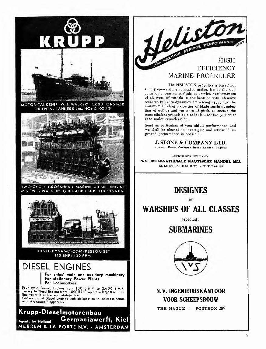
M O T O R - T A N K S H I P " W . B. W A L K E R " 1 5 , 0 0 0 T O N S F O R
O R I E N T A L T A N K E R S L t d . , H O N G K O N G
T W O - C Y C L E C R O S S H E A D M A R I N E D I E S E L E N G I N E
M . S . " W . B . W A L K E R " 3 , 6 0 0 - 4 , 0 0 0 B H P : 1 1 0 - 1 1 5 R P M .
Krupp-DieselmotorenbauAgents lor Holland: G er m a n i a wer ft, Kiel M E R R E M & L A P O R T E N .V . - A M S T E R D A M
DESIGNES
WARSHIPS OF ALL CLASSESespecially
SUBMARINES
N.V. INGENIEURSKANT00R VOOR SCHEEPSBOUW
THE HAGUE - POSTBOX 289
HIG HEFFICIENCY
MARINE P R O PE L L E RThe HELISTON propeller is based not
simply upon rigid empirical formulae, but is the outcome of unceasing analysis of service performances of all types of vessels in combination with intensive research in hydro-dynamics embracing especially the minimum lift-drag properties of blade sections, selection of outline and variation of pitch, to secure the most efficient propulsive mechanism for the particular case under consideration.Send us particulars of your ship’s performance and we shall be pleased to investigate and advise if improved performance is possible.
J. STONE & COMPANY LTD.O cean ic H ouse , C o ck sp u r S t r e e t , L o n d o n , E n g lan d
AGENTS FOR H O LLAN D :
N.V. INTERNATIONALE NAUTISCHE HANDEL MM.13, K O R T E jV O O R H O U T - T H E H A G U E
D I E S E L - D Y N A M O - C O M P R E S S O R - S E T 1 1 5 , B H P : 4 3 0 R P M .
D IE SE L E N G IN E S
1■ F o u r - c y c l e D i e s e l . E n g in e s f r o m 1 0 0 B . H . P . to 2 , 6 0 0 B . H . P . H T w o - c y c l e D i e s e l E n g in e s f r o m 1 , 0 0 0 B .H .P . u p to t h e l a r g e s t o u tp u t s .■ E n g in e s w i th a i r l e s s a n d a i r - i n j e c t i o n .I C o n v e r s i o n of D i e s e l e n g i n e s w i th a i r - i n j e c t i o n to a i r l e s s - i n j e c t i o n H w i th A r c h a o u io f f a p p a r a t u s .
For ships’ main and auxiliary machinery For stationary Power Plants For Locomotives

THE R O T T E R D A M D R Y D O C K CO M PA N Y
PHOTO K. L. M. PHOTO K. L. M.
B I R D S - E Y E V I E W OF T H E R O T T E R D A M Y A R D B I R D S - E Y E V I E W O F T H E S C H I E D A M Y A R D
REPAIRERS - SHIPBUILDERS - ENGINEERS
14 SLIPWAYS UP TO 6 0 0 Ft LENGTH
7 FLOATING DOCKS UP TO 20.000 TONS CAPACITY

A new and superior type of plywoodinsuring even greater satisfaction than can be obtained from using the standard type of Oregon Pine plywood
HARBORD SUPER PLYWOODT H E B E S T P L Y W O O D F O R S H I P B U I L D I N G P U R P O S E S
Saving in weight Increased strength and flexibility
Extreme resistance to moisture, also to molds, fungi and insects A better finishing surface
Ease o f working
F or particu lars apply to
N .V . H AN D ELM AA TS C H A P P IJ FE N N IA - T H E H A G U E
i. ......THE "GORCH FOCK” EQUIPPED WITH K A W • BATTERIES
K A WACCUMULATORIN LEAD OR STEEL
FOR ALL PURPOSES
50 y e a rs experience
ACCUMULATOR
GOTTFRIED HAGEN, Aktiengesellschaft • KÖLN-KALKG en era l R epresen ta tives fo r H o lla n d :
VAN RIETSCHOTEN & HOUWENS’ E. M. N.V. - BATTERY-DEPARTM ENT - ROTTERDAM469-179, WESTZEEDIJK - TEL. 35020

THE “ARCFORM” DESIGN( lsh e rw o od Patent)
HAS BEEN PROVEDBY
EXPERIENCE W ITH ARCFORM SHIPSAT SEA
TO BE THE MOST ECONOMICAL
SIR JO SE P H W. ISHERWOOD & CO. LTD.4, Lloyds Avenue, London E. C. 3 — 17, Battery Place, New York, U. S. A.
A g en ts fo r H o lla n d :
N.V . IN TE R N A TIO N A LE NAUTISCHE HANDEL MAATSCHAPPIJ - 13, KORTE V O O R H O U T - TH E HAGUE
COMPRESSORLESS DIESEL ENGINES
FO UR-STRO KE D i e s e l e n g i n e s 150—800 B.H.P. f o r M a r i n e - A u x i l i a r y s e t s
SCAVENGE-PUMP M a r i n e D i e s e l s 50—300 B.H.P. DIRECT REVERSING t y p e s f r o m 75 B.H.P. u p w a r d s
HIGH SPEED COLD STARTING D i e s e l e n g i n e s
FROM 6 B.H.P. U PW ARD S
N.V. CROSSLEY MOTOREN - TH E HAGUE7 , W E T E R IN G K A D E
P N C METAALis b e t e r dan elke bronssoort
om de volgende eigenschappen:
HOGERE rek, vastheid, hardheid, weerstand tegen aantasting en slijtage
LA G ERE wrijv ing,sm eltverliezen, soortelijk gewichtSM E E D B A A R , L A S B A A RGE M A KK E LIJK TE GIETEN (ook dunwandig)GEEN POREUZE P L A A T SE N
Vraagt inlichtingen en offerte bij:
N .V . TECHNISCH BUREAU VAN G. L. DAHLMANNPO ST B U S 242 R O T T E R D A M
i i A i r c i t t C O N D E N S E R T U B E Sin A l u m i n i u m - B r a s s (B .N .F . Pat. N o . 308647) Brass, C u p ro -N ic k e l and o th e r A l l y
Seamless COPPER and BRASS TubesDiameters up to 24in«
CONDENSER PLATES : : FERRULES, Etc.
T h e B ir m in g h a m B a t t e r y & W e ja l C o m p a n y U dSELLY OAK :: BIRMINGHAM :: ENGLA
/gents ; N. V. Technlsch Bureau Stephen Adam, e" aa®

BLe CO " SHIP'S CABLE(R E G D . T R A D E M A R K ) , OF CAST STEEL
l|bgHHRA 40 % stronger than wrought iron cables'> a , p - 1 -p^< *• As supplied to Motor
ƒ/* W -V I i j L *J9 Tanker “G. s. Walden”
' - ■ . y BROWN, LENOX & CO. LTD. P O N TY P R ID D■ The original makers of ships’ anchor chains S. W ales
British Admiralty Contractors since 1808
a g e n t s : n . y . t e c h n i s c h b u r e a u S t e p h e n a d a m - p o s t b o x 36 2 - t h e h a g u e
m.s. “G. S. WALDEN”, the largest tanker ever built in the Netherlands . . .
H A S BEEN CO M PLE TE LY RIGGED
AN D A L L A W N IN G S ETC. H AVE BEEN M AD E BY
N .V . H A N D E L S C O M P A G N IE at ROTTERDAM65, B O O M P JE S
IN FACT THE MOST IMPORTANT SHIPS’ RIGGERY IN THE NETHERLANDS
The order has been executed in the shortest possible time by a num ber of trained, experienced men who provided the precision and fitting on board. R eal experts were making the final adjustments in our works before starting the fitting on board that w ill prove accuracy, long life and finer performance.
In the past twenty years a number of ships belonging to different important companies, have been completely rigged by our company. W e only mention:
Koninklijke Paketvaart Maatschappij Koninklijke Nederlandsche Stoomboot M ij.Nederlandsch Indische Tank Stoomboot M ij.N.V. Maatschappij VrachtvaartN.V. De Rotterdamsche Droogdok MaatschappijN.V. Machinefabriek en Scheepswerf van P. Smit Jr .Koninklijke M arine
HAARLEMSCHE KUNSTBRONS, M ETA A LG IETER IJ EN D R A AIER IJF. ROESSINGH VAN ITERSON
41, BAK EN BSSBRG RACH T, H A A R L E M (H O LLA N D ) — TE LE PH O N E 14843
Delivering of all kinds of bronze, brass, aluminium and sulimin castings, machined or unmachined, according to models and drawings at low prices. Suppliers to the
largest Shipbuilding-Yards and Machinery-Works at home and abroad
DELIVERING ALSO ACCORDING TO A N A L Y S E S

G . S . W A L D E NPresident Standard Vacuum O il Company
N ew Jersey

S c h i p en W e r f(S H IP & Y A R D )
PU BLISH ED E V E R Y FO RTNIG HT. D EVO TED TO S H IP B U IL D IN G , N AVIG ATIO N AND P O R T STO W H IC H H AS BEEN AD M ITTED THE M O N T H LY "DE TECH N ISCH E K R O N IE K ” VOL. X
, VEREENIGING VAN TECHNICI OP SCHEEPVAARTGEBIED ORGAN OF THE I CENTRALE BOND VAN SCHEEPSBOUWMEESTERS IN NEDERLAND
( SCHEEP- EN LUCHTVAARTKUNDIG INSTITUUT EN MUSEUMiiiiiiiiiiiiiiimiiiiiiiiiiiHilnïïniTiïiiiiiiiiiiiiiiimiiiiiïïiïimïïlïïimïïïïïiïMiFiiiniiiiiiM
HONOURARY COMMITTEE:P. A . AR R IË N S, D irector o f the N . V . H olland-
sche Stoomboot Maatschappij, Am sterdam J. D. B R A N D , D irector o f the N. V . Koninklijke
Paketvaart Maatschappij, Am sterdamA . F. BRO N SIN G, D irector of the N . V . Stoom -
vaart-M aatschappij “N ederland”, Am sterdamN. W . C O N IJN , D irector of the N .V . W e rf
“Gusto” v/h Firma A . F. Smulders, Schiedam G. H. CRO N E, President of the Chamber of
Commerce, Am sterdam Ir. M. H. DAM M E, D irector o f the N . V . W e rk
spoor, Am sterdam L. C. M. V A N EENDENBURG, Secretary o f the
Board o f Directors o f the N .V. Vereenigde N eder- landsche Scheepvaart-M aatschappij, The Hague
D. C. EN D ERT Jr ., D irector o f the N .V . De R ot- terdamsche Droogdok Maatschappij, R otterdam
W . A. EN GELBRECH T, President of the Chamber of Commerce, Rotterdam
J. W . B. EVERTS, President-D irector o f the Koninklijke Paketvaart Maatschappij in N etherlands India, Batavia
D. GOEDKOOP Dzn., D irector o f the N .V . N eder- landsche Scheepsbouw-Maatschappij, Am sterdam
A. J. M. G O U D R IA A N , President o f the Board of D irectors o f the N .V . Van N ievelt, Goudriaan & C o’s Stoom vaart-M aatschappij, R otterdam
J. W . J . B AR O N V A N HAERSOLTE, D irector of the Scheep- en Luchtvaartkundig Instituut en Museum, Rotterdam
M. C. K O N IN G , ex-D irector of the N. V . Stoom vaart-M aatschappij “Nederland”, Am sterdam
Prof. P. M EYER, Professor to the Technical U niversity, D elft
B. C. V A N OMMEREN, D irector o f the N .V . Phs. van Ommeren’s Scheepvaartbedrijf, R otterdam
Ir. J. O VE R W E G , D irector o f the N . V . M achinefabriek Gebrs. Stork & Co., Hengelo
C. POT, D irector o f the N. V . Electrotechnische Industrie v/h W . Smit & Co., Slikkerveer
P. J. R O O SE G A A R D E BISSCHOP, D irector of the N . V . Java-C hina-Japan Lijn, Am sterdam
B. E. R U Y S, D irector o f the N . V. Rotterdam sche Lloyd, Rotterdam
S. M. D. V A L S T A R , D irector o f the N .V . K oninklijke Nederlandsche Stoomboot M aatschappij, Amsterdam
W . V A N DER VO R M , D irector o f the N .V . Scheepvaart & Steenkolen-Maatschappij, R o tterdam
Ir. H. C. W ESSELING, D irector o f the N . V . K o ninklijke Maatschappij “De Schelde”, Flushing
EDITORIAL STAFF:CHIEF EDITORS:
Ir. J. W. HEIL, w. i. Ir. G. DE ROOIJ, s. i. G. ZANEN
Secretary o f the Editorial S taff 12 , W estnieuw land, R otterdam C., Telephone 22200 (2 lines)
SUB EDITORS:Prof. J . C. AN D RIESSENJ. BAKKE RIr. L. W . B A STIr. W . V A N BEELENIr. G. BEEREN BORGP rof. D r. ir. C. B. BIEZENOIr. P. BOELEW . V A N D ER BO RNIr. A . H. TEN BRO EKP rof. ir. G. B R O U W E RIr. B. E. C A N K R IE NIr. J . C R A M E RP. F. DE D E CKE RIr. E. V A N DIERENL. F. H. D IR K Z W A G E RP rof. ir. D . D RESD ENIr. W . GERRITSE NTH . V A N D ER G R A A FB. C. DE G R O O TJ. F. GU GELO TP. G U IL O N A R DIr. M. F. G U N N IN GF. C. H A AN E BR IN K W . A . HOEKTr. C . H. HOLGENIr. L. B. DE H OOPP. IN TVELDTr. L. JA C O B SIr. H. F.. JA E G E RIr. J . JAN SZENIr. M. C. DE JO N GJ. DE K A N T E RIr. C. KAPSEN BERGP rof. N. K A LD r. J. H. KEMME, physicianJ. V A N KERSENN. KLEINIr. F. W . K . DE K L E R K Ing. E. KLIN GELFU SS D r. Ing. J . J . K O C H Ir. H. J. K O O Y J r .Ir. W . KRO PH O LLE R Ir. W . H. K R U Y F FD. DE K W A A D ST E N IE T Ir. H. W . V A N D ER LEE P rof. ir. A . J . T E R LINDENB. J. LOOSG. J . L U G TIr. H. J. M A T H L E N E R LOD ERUSF. C. M AT ZIN G E RIr. H. M. MEIER M A T T E R NIr. P. E. M EYERD r. ir. W . M. M EIJERIr. J . C. M ILBO RN
Ir. A . J. MOLLINGER Ir. F. MULLER D r. ir. W. J. MULLER Prof. ir. J. MUYSKENA. A . NAGELKERKE W . D. V A N OSIng. L. VAN OUW ERKERK J. A . L zn . Ir. J . S. PEL J . C. PIEKIr. K . VAN DER POLSIr. H. N. PRINSM r. D r. ir. A . W . QUIN TM. RO BAARDIr. W . H. C. E. RÖSINGHIr. J . ROTGANSE. O. H. M. RUEMPOL Ir. D. T. RUYSC. J. RIJNEKEIr. W . P. G. SARIS D r. Ing. F. SASSF. A. SCHIEFERIr. A . M. SCHIPPERS Dr. P. SCHOENMAKER J . J . SCHOOD. SCHOUTEN Hzn.Prof. D r. Ing. E. H. SCHULZIr. R . SMIDIr. H. C. SNETHLAGER. F. C. STROINKIr. J. J . TERWIELProf. ir. E. J. F. THIERENSIr. C. THOMSD r. J . H. VAN DER TU U KJ. VAD E RD r. ir. H. V A N DER VEENB. VERH EYC. VERM EYC. VEROLMEIr. J . VERSCHOORE. VLIGA . A . VOETELINKDip. Ing. P. B. VOSProf. E. J. VOSSN ACKIr. G. DE VRIESH. DE VRIESIJ. L. DE VRIESJ. W . WILLEMSENMr. J. WITKOPD r. ir. E. B. WOLFFIr. J . C. G. VAN W IJKProf. ir. C. M. V A N W IJN G A A R D E NIr. A . H. VAN IJSSELMUIDENIr. J . IJZERC. ZUL VER
A n n u al subscription, post paid and payab le in advance, at home ƒ 7.— , abroad ƒ 8.5 0. Single copies ƒ 0 .40. A dvertisem ents ƒ 0 .40 a line, by co n tra c t reduction
PUBLICATION OF THE N .V . DRUKKERIJ M. W YT & ZONENB A N K I N G A C C O U N T 58458, T E L E P H O N E 35250 (4 lines)
H I , P I E T E R D E H O O C H W E G, R O T T E R D A M WW 2 7 5 6

D Y S E R I N C K ’ S O I L
C om pound-M arine-Iingine-oih
Steam -C ylinder-oils M otor- C ylinder-oils
Turbine-oils Greases
7
N.V. OLIEHANDEL VAN DYSERINCK ZONEN75, SCHALK.WIJKER'WEG, HAARLEM,TEL. 10047
The Anti-Corrosive Paint
forming a le a d -a rm o u r! THE O N LY PERFECT -------------------------------------------------ANTI-CORROSIVE PAINT FOR TANKERSPossessing great resistance against petrol and benzine
M A N U F A C T U R E R S : Estab lished 1643
N.V. HEYME VIS & ZOONENE L D E 5 T
PMNT-SUPPUERS ZAANDAM (Holland)M O D E R N E S T W O R K S
D r i v e b y
R E N O L D C H A I N
For improved camshaft operation on marine Diesel auxiliary and main engines standardise on Renold chains N eat m echanical arrangem ent is possible to a greater degree than with any other method, and their reliability is proved by their increasing use.
Our technical service and experience is freely a t your disposal
RENOLD CHAINS LTD.TELEPHONE 30080
DEPOT OF
THE RENOLD & COVENTRY CHAIN CO. LTD. - EN GLAN DM A N U F A C T U R E R S O F C H A IN C O U P L IN G S — C H A IN C L U T C H E S — C H A IN D R IV E S — R E N O I .l) C O N V E Y O R C H A IN S , E TC .
Painted with A r c a n o l M .S . "MODJOKERTO”
C IR C U L A R S A N D S A M P L E S O N A P P L IC A T IO N
TH E M O TO R TA N KSH IP “G. 5. W ALD EN ”THE FIRST ARC-FORM TANKER
BY
G. M . H. C H A M B E R S, F. R. S. A. M . I. N. A.
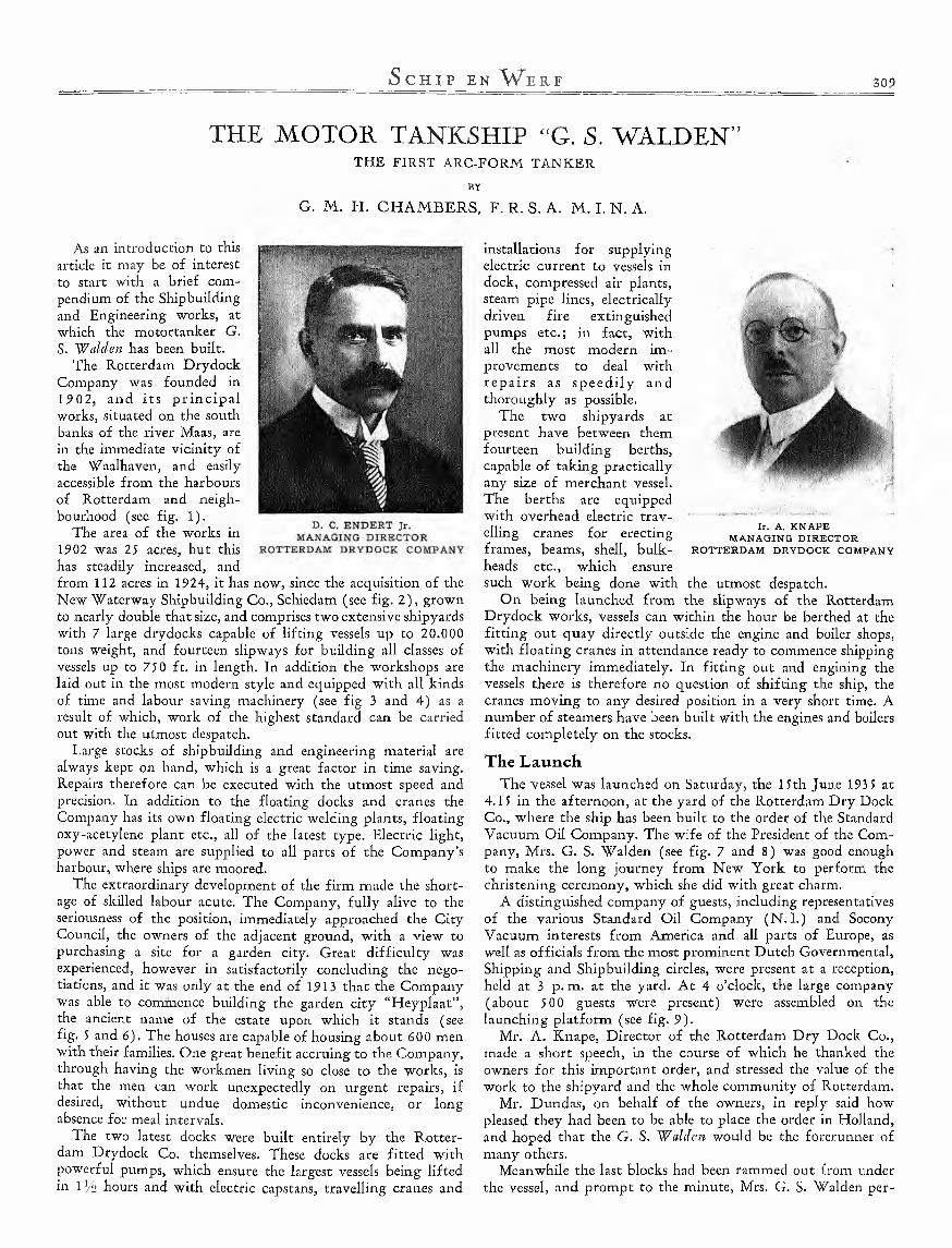
As an introduction to this article it may be of interest to start with a brief compendium of the Shipbuilding and Engineering works, at which the motortanker G.S. W alden has been built.
The Rotterdam Drydock Company was founded in 1902, and its p r in c ip a l works, situated on the south banks of the river Maas, are in the immediate vicinity of the Waalhaven, and easily accessible from the harbours of Rotterdam and neighbourhood (see fig. 1).
The area of the works in 1902 was 25 acres, but this has steadily increased, and from 112 acres in 1924, it has now, since the acquisition of the New "Waterway Shipbuilding Co., Schiedam (see fig. 2 ) , grown to nearly double that size, and comprises two extensive shipyards with 7 large drydocks capable of lifting vessels up to 20.000 tons weight, and fourteen slipways for building all classes of vessels up to 750 ft. in length. In addition the workshops are laid out in the most modern style and equipped with all kinds of time and labour saving machinery (see fig 3 and 4) as a result of which, work of the highest standard can be carried out with the utmost despatch.
Large stocks of shipbuilding and engineering material are always kept on hand, which is a great factor in time saving. Repairs therefore can be executed with the utmost speed and precision. In addition to the floating docks and cranes the Company has its own floating electric welding plants, floating oxy-acetylene plant etc., all of the latest type. Electric light, power and steam are supplied to all parts of the Company’s harbour, where ships are moored.
The extraordinary development of the firm made the shortage of skilled labour acute. The Company, fu lly alive to the seriousness of the position, immediately approached the C ity Council, the owners of the adjacent ground, w ith a view to purchasing a site for a garden city. Great d ifficu lty was experienced, however in satisfactorily concluding the negotiations, and it was only at the end of 1913 that the Company was able to commence building the garden city “H eyplaat”, the ancient name of the estate upon which it stands (see fig. 5 and 6). The houses are capable of housing about 600 men with their families. One great benefit accruing to the Company, through having the workmen living so close to the works, is that the men can work unexpectedly on urgent repairs, if desired, without undue domestic inconvenience, or long absence for meal intervals.
The two latest docks were built entirely by the Rotterdam Drydock Co. themselves. These docks are fitted with powerful pumps, which ensure the largest vessels being lifted in l ]/2 hours and with electric capstans, travelling cranes and
installations for supplying electric current to vessels in dock, compressed air plants, steam pipe lines, electrically driven fire extinguished pumps etc.; in fact, with all the most modern improvements to deal with re p a irs as sp e e d ily and thoroughly as possible.
The two shipyards at present have between them fourteen building berths, capable of taking practically any size of merchant vessel.The berths are equipped with overhead electric travelling cranes for erecting frames, beams, shell, bulkheads etc., which ensure such work being done with the utmost despatch.
On being launched from the slipways of the Rotterdam Drydock works, vessels can within the hour be berthed at the fitting out quay directly outside the engine and boiler shops, with floating cranes in attendance ready to commence shipping the machinery immediately. In fitting out and engining the vessels there is therefore no question of shifting the ship, the cranes moving to any desired position in a very short time. A number of steamers have been built with the engines and boilers fitted completely on the stocks.
The LaunchThe vessel was launched on Saturday, the 15th June 1935 at
4.15 in the afternoon, at the yard of the Rotterdam Dry Dock Co., where the ship has been built to the order of the Standard Vacuum Oil Company. The wife of the President of the Company, Mrs. G. S. Walden (see fig. 7 and 8) was good enough to make the long journey from New York to perform the christening ceremony, which she did with great charm.
A distinguished company of guests, including representatives of the various Standard Oil Company (N .I.) and Socony Vacuum interests from America and all parts of Europe, as well as officials from the most prominent Dutch Governmental, Shipping and Shipbuilding circles, were present at a reception, held at 3 p. m. at the yard. A t 4 o’clock, the large company (about 500 guests were present) were assembled on the launching platform (see fig. 9).
Mr. A. Knape, Director of the Rotterdam Dry Dock Co., made a short speech, in the course of which he thanked the owners for this important order, and stressed the value of the work to the shipyard and the whole community of Rotterdam.
Mr. Dundas, on behalf of the owners, in reply said how pleased they had been to be able to place the order in Holland, and hoped that the G. S. W alden would be the forerunner of many others.
Meanwhile the last blocks had been rammed out from under the vessel, and prompt to the minute, Mrs. G. S. Walden per-
I r . A , K N A P E M A N A G IN G D IR E C T O R
R O T T E R D A M D R Y D O C K C O M PA N Y

F ig . 1. B IRD S-E Y E V IE W OF TH E RO T T E R D A M Y A R D P h o t o K .L .M .
formed the time honoured ceremony of breaking the bottle on the vessel’s bows, at the same time naming the ship G. S. W alden , and the new tanker slid down the ways, to the cheers of the assembly (see fig. 10).
Some particular detailsThis is the first vessel that the Rotterdam Dry Dock Co.
have had the pleasure of building for the Standard interests, but they are fortunate in having another, the Benakat, on the stocks next to the G. S. W alden, which however is being built for one of the Dutch companies, the Nederlandsche Koloniale Tankvaart Maatschappij, to the design of the Standard Shipping Company. Mr. A.Schneider, of Hamburg, has the supervision of this new building under his charge, both for the ship and machinery.
Fig. 11, 12 and 13 show some stadia during the building of the hull of the G. S.W alden.
In addition to being the largest oil tanker ever yet built in Holland, the G. S.W alden is also the first tanker in the world to be designed and built on the “Arcform” principle, patent by Sir Joseph Isherwood.The new form (see fig. 14
*) M a r k e d w it l i se e b eh in d .
and sheet I*) 1), attracted a great deal of attention, and many of the experts were obviously impressed by the clean run of the underwater lines of the vessel. Above water, the form is quite normal, so that little or nothing can be seen, with the vessel in ballast or loaded condition, to distinguish her from a vessel of orthodox design.
Yet another interesting feature of the vessel is the tank top in the engine room, which also does service as the motor foundation. The floors, longitudinal girders, centre girder and tank top were all electrically welded in the workshop, and the whole, weighing about 65 tons, was lifted into place on board (see fig. 15). Remarkable is that the holding down bolts of the engine bedplate do not pierce the tank top.
The G. S. W alden is 48 5'B.P. X 74'-10" X 37' mid., and carries 15,420 tons deadweight on 30'-41/i" draft. The vessel was launched on a single way, 5 5" broad, and the launching weight was about 5500 tons, the maximum pressure when the stern lifted being well over 1300 tons. The vessel has been built under the special survey of Lloyd’s Register of Shipping, on the Isherwood Bracketless System, and is to be registered under the English Flag. The upper deck of the vessel is continuous, and

F ig . 3. 5 E N D E R T -C U R C H IN PU N C H IN G T A B L E S IN P L A T E R S ’ SH E D S OF R . D. M.
the erections consist of poop, bridge and forecastle, connected by a continuous fore and aft gangway.
SubdivisionThe vessel is subdivided as
follows: Commencing fromforward: Fore peak, separated from the forward fuel bunker by the collision bulkhead. This bunker is subdivided by an oiltight centre line bulkhead into two compartments, aft of which is situated the forward pump room. Then follows the first of main tanks,Nos. 1, 2, 3, 4 and J, above which are Nos. 1. 2 and 3 summer tanks. The main pump room is situated aft of No. 5 tank, and tanks Nos.6, 7, 8 and 9, cofferdam, and fuel oil bunker occupy the space from the pump room up to the machinery bulkhead. Summer tanks 4 and 5 are above main tanks 6 to 9.The after end of the machinery space is bounded by the aft peak bulkhead. The main tanks and the summer tanks have a total capacity of 19.777 m3, after allowing 2 °/o for expansion. Tanks for fresh water, lubricating oil, cooling water and feed water are arranged in the double bottom under the machinery space. A boatswain’s store is situated under the forecastle head, immediately aft of
which is the forehold, separated from the summer tanks by a cofferdam (see sheet IP ) .
AccommodationThe upper deck space under the bridge is arranged for
stowing the oil hoses on the port side, while two rooms fordeck stores are fitted on the starboard side, all bulkheaded with steel. The bridge erection consists of lower bridge, boat deck and navigating bridge.
On the lower bridge are housed, the chief officer, 2nd and 3rd officers, doctor, wireless operator and purser. These cabins are all very roomy, and tastfully and comfortably furnished. There are three bath rooms on this deck, an oilskin locker, pantry and a separate compartment for the Sperry gyro compass installation. The dining saloon is situated in the centre of the house, and is panelled in polished Slavonic oak, with mahagony framing, with snuff coloured upholstery and curtains.
The captain’s house, consisting of day room, sleeping quarters and bathroom, is on the boat deck, as is also the wireless operating room. Inside stairways are provided in

F ig . 5. B ISO N G ATE W AY IN TH E H E Y P L A A T G ARDEN C ITY
the captain’s house for access both to the lower and navigating bridges. The captain’s quarters are sumptuously furnished in first class style. The chart room and wheel house, constructed of teak, are on the navigating bridge, and the standard compass is placed on top of this house. A special compartment is arranged in this house for the Sperry "Mother” gyro compass, which has repeaters on navigating bridge, on aft end of poop- deckhouse and at standard compass. A Sperry automatic steering device is fitted on the navigating bridge.
The engineer’s quarters are situated on the poop deck, with the crew in the poop space on the upper deck below. Accommodation is provided fir nine engineers and assistants, while the Chief engineer has his own office and bathroom. The engineers’ messroom at the after end of the casing has seating accommodation for 12 persons, and is neatly panelled and tastefully furnished.Provision has been made for a crew of 40 men, with ample washing and toilet accommodation.
The refrigerating chambers for fresh meat and vegetables are aft of the
crew space. The white and native galleys are fitted respectively with Todd’s oil burning range and coal fired range, two steam jacketted 10 gallon capacity, monelmetal Stockpots, each 24” X 14" X 14" deep inside, and one steam heated Hot-press, 2'-9" X 2'-0" X 3'-0" high fitted inside with galvanized perforated shelves. Nickel- silver Bain-Marie, portable carving trays and covers and Hardwood carving board, supplied by JohnPhillips & Co., Glasgow, are ample in size for the number of men on board.
RiggingThe rigging work, as
well as the sail-loft work has been executed by the N. V. Handelscompagnie,Rotterdam, one of the most important firms in this branch. It may be
noted that this firm has been compelled by certain circumstances to execute this order in the shortest possible time.
Many individual parts had to be so thouroughly prepared that they would each fit perfectly in their appointed places on board the ship and there was never allowed a minute’s delay on the assembly line on board.

Fig. 7. M R S. AND MR. G. S. W A L D E N Fig. 8. MRS. G. S. W A LD E N AND MR. A. K N A PEA R R IV IN G A T THE RO TTERD AM D RY D O C K Y A R D W A L K IN G TO THE LAUNCH ING PL A T F O R M
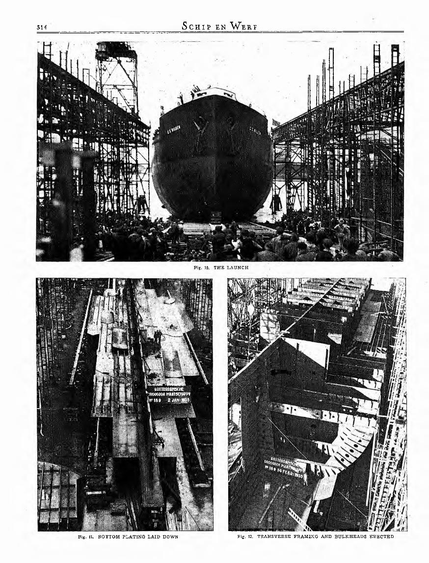
Fig. 10. THE LAUNCH
I * » ® - '' ‘L
Fig. 12. TR AN SVE R SE FR AM IN G AND BU LK H E AD S ERECTEDFig. 11. BOTTOM PLATIN G LAID DOWN

Fig. 13. ERECTIN G B U LK H E AD S
The steel wire ropes are of the strongest material. No thimbles have been spliced in as usual, but the end of each steel wire rope has been provided with a special socket, cast to the wire ropes with lead. For the manufacture of the awnings, a cotton duck of a very fine quality has been used. The cargo- booms or derricks are not finished in the usual way, but provided with heavy manila hanger-tackles with wooden blocks.
When glancing over the ship, its rigging and the many awnings make a very pleasant impression. The many awnings w ill keep the different decks cool in tropical weather.
Sanitary arrangementsThe lavatories, shower baths and wash basins in the accom
modation are served by two sanitary tanks, one is up on the bridge for the midship house, and one on the poop for the after accommodation. The lavatories and showers for the engineers and the deck officers and also in the captain’s bathroom have hot and cold running water, and the wash basins in the rest of the accommodation cold water only. The hot water for the hygenic services midships is produced electrically, while that for the after accommodation is steam heated.
Fire fighting arrangementsThe fire extinguishing plant consists of a main pipe line for
wash deck and fire service, running under the fore and aft gangway. Branches are led from this line and terminate with special valves for coupling the fire hose. These lines are of sufficient number and so distributed, that any point of the
Fig. 14. VE SSE L DURING CONSTRUCTION SH OWING T Y P IC A L ARCFO RM
hull and superstructure can be reached by the normal jet, when the hose is coupled to the nearest connection. A Lux 3 2 cylinder COo fire extinguishing plant is installed in the steering house, for extinguishing fire outbreaks in the machinery space. A steam smothering system is laid on for all main and summer tanks, pump rooms and cofferdams. Minimax hand fire extinguishers are fitted in handy places throughout the ship and in the accommodation.
It is a well accepted fact that hand fire extinguishers are
Fig. 15. TRAN SPO RT OF THE COM PLETE E L E C T R IC A L L Y W E L D E D MAIN MOTOR SEATING W ITH DOUBLE BOTTOM TO TH E BU IL D IN G BERTH

the most appropriate extinguishing devices for combatting incipient fires.
The following Minimax devices were installed:
6 Minimax liquid extinguishers "B” ;
7 Minimax dry powder extinguishers "Tro 5” ;
9 Minimax hand foamextinguishers “ES K 10”.
The conically formed Minimax liquid extinguisher “B”(see fig. 18) is in general one of the best-known hand fire extinguishers. The operation of the Minimax “B” extinguisher is the easiest immagin- able. The M in im ax d ry powder extinguisher "Tro 5”(see fig. 19) is one of the most recent developments of the Minimax Company; in its creation, the company made vast use of its many year’s experience with its other typesof extinguishers. The apparatus is distinguished particularly by the presence of a movable nozzle which permits the
Fig. 1(5. NEARING COM PLETION
directing of the stream in all directions, even directly upwards.In addition to that equipment, 9 Minimax hand foam
extinguishers "ES K 10” were likewise installed, as already mentioned.
The devices installed on this tank ship display a construction speciality in as far as the inner containers are provided with
locks which may be activated from without by means of levers. For this reason, therefore, it is impossible, for instance, for the liquids contained in the apparatus to mix prematurly due to the rolling or pitching of the ship.
Fig. 18. M INIM AX
LIQUID EXTIN GUISH ER
“B ”
Fig. 19, M IN IM AX
D RY PO W D E R EXT IN G U ISH ER
“ TRO 5”

Fig. 21. CAST STEEL STERN FR A M E
rolled bulb steel tee bar, and the gunwale is also of special rolled double steel bulb angle.
The boats are fitted with Mills patent disengaging gear.
W inchesThere are three steam winches, fitted on the upper deck and
one steam warping winch of 230 mm cyl. diameter and 300 mm stroke, delivered by the Atlas Werke, Bremen, represented in Holland by Messrs. W. C. & K. de W it, Amsterdam.
The cargo winches are driven by twin steam engines of 180 mm cyl. diameter and 300 mm stroke, with link motion
The lifeboats, four in number, two housed on the bridge and the other two on the poop, were supplied by Meehans Limited, Scotstoun Iron Works, Glasgow, and are of steel, constructed on Meehans patent pressed steel principle, double ended class 1 A, 24 ft in length X 8 ft beam X 3 '-3" deep with a capacity of 37 persons each.
These boats are fitted with Meehans patent keel angle.
The keel, stem and sternpost are of special
Lifeboats

Fig, 23. M AIN MOTOR
reversing gear. The steam cylinders and the copper steam pipes are insulated with glass silk and jacketed with galvanized sheet-iron. The piston and slide valve rods are of bronze. The winches are provided with double purchase, spur wheels with machine-cut teeth, the wheels being of cast-iron and the pinions of steel. The couplings slide on squared sections of the shaft. The main shaft carries the drum and the warping ends, the latter being provided with cast-on ribs. Two of the winches have extended shafts with special outer bearing brackets mounted on wrought-iron foundations. All bearings are
adjustable and bronze bushed. A ll lubricating cups have leather packing and screw caps. The steam valve is of bronze.
The construction of the warping winch corresponds to the above description, except that the winch has no centre barrel and is provided with large warping ends on the extended shafts.
Windlass, anchors and chainsOne Atlas Werke windlass for 2G/a,, chain is driven by a
horizontal twin steam engine of 300 mm diameter and 3 0 mm stroke with reversing valve. The steam cylinder are jacketed and

Fig. 24. SCA VE N G IN G PU M PS AT B A C K SID E OF M AIN MOTOR
insulated with glass silk. The copper steam piping between the reversing valve and the steam cylinder are insulated in the same way. The piston and slide valve rods are of wrought bronze. The crank shaft is supported in two strong bearings. The crosshead bearing, crank pin bearing, crank shaft bearings and the eccentric straps are of bronze and adjustable. The crank shaft carries a S.M. steel pinion which meshes with the cast steel wheel. The purchase shaft runs in 4 strong frames in adjustable bronze bushed bearings and carries the warping ends; these are special castings and are provided with cast-on ribs. The purchase shaft also carries the cast steel pinions sliding on squared sections of the shaft and which are shifted for disengaging the cable holders. The main shaft is made in two parts, the cable holder is connected to the cast steel wheel by means of a clutch, and each shaft is supported in two bronze-bushed bearings. The cable holders are provided with strong brakes with toggle- joint motion and provided with grooves. The whole mechanism is assembled on a strong cast bedplate, provided with an rim to prevent oil soiling the deck.
All moving parts are furnished with a well-designed lubrication. All lubricating cups are provided with leather packing and screw caps. Hand drive is not provided. With 7 atm. steam
pressure the windlass lifts simultaneously 2 anchors with 3 0 fathoms of chain each.
The total weight of anchors and chains for the vessel is 68 tons.
Steering gearThe rudder (see sheet which is of the
Oertz type, is served by an Atlas Werke vertical steam steering gear of 220 mm cylinder-diameter and 220 mm stroke (see fig. 20). The vertical twin steam engine is fitted on a sliding baseplate which is bolted to the deck. A S.M. steel worm on the crank shaft meshes with a cast steel worm wheel with bronze rim. A pinion of special steel is keyed on to the worm wheel shaft and meshes with the cast steel toothed quadrant. The teeth of the worm drive, quadrant and pinion are milled. The rim of the quadrant consists of a number of exactly similar toothed segments of S.M. steel, so that the centre segment, the teeth of which are subjected to considerable wear and tear, can easily be replaced by one of the outer segments. The S.M. steel tiller is firmly keyed on to the ruddershaft but in order to absorb the heavy shocks due to heavy seas striking the rudder, the quadrant is loose on the ruddershaft and the elastic connection between the tiller and the quadrant is effected by means
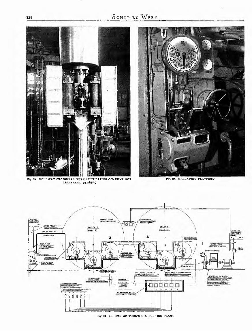
F ig , 26. F O U R W A Y C R O SSH E A D W IT H L U B R IC A T IN G O IL P U M P F O R C R O SSH E A D BEARIN G
F ig . 27. O P E R A T IN G P L A T F O R M

of strong buffer springs. Provision is made for a fixed connection in case the flexible connection should fail. The steam engine is disconnected by sliding it back along the baseplate.
The hand steering gear is of the quadrant type, with steering column in the steering engine compartment, with 2 large teakwooden hand wheels of 1800 mm diameter. The connection of this gear is effected by putting the pinion into the gear with the auxiliary quadrant, after having disconnected the engine.
The steering engine is controlled from the navigation bridge by means of a h ydraulic motor. The telemotor transmitter is arranged on the bridge and the telemotor receiver is fitted on the steering engine. A double line of copper piping connects the transmitter and the receiverof the telemotor. The steering engine can also be worked from As a third means of steering, a small steering wheel is fitted the poop deck by means of a brass steering column with hand on the steering engine proper.wheel and the necessary transmission shafting. On the navigation bridge an automatic Sperry steering
device has been installed.
The sternframeThe sternframe (see fig. 21 and sheet V *), made in 4 pieces
and fitted together, weighs 32,300 kg and the largest dimensions
1 F u e l o il in le t2 F uel o il ou tle t3 A ir ou tle t4 D r a in a g e5 A ir o u tle t6 Cleaning p o rts7 T herm om eter8 T w o -w ay cocks

are: 11,000 X 10,600 X 1800 mm, the largest piece being 8500 X 2400 X 1800 and weighing 10,400 kg.
These castings were made from first class S.M. cast steel to the requirements of Lloyd’s Register and were manufactured
been the object of special study. The equipment includes devices fulfilling all the most up-to-date maritime requirements. The gyroscopic compass equipment is fitted up in an enclosed space in the midships deckhouse. In the chartroom is the control for the aerial of the direction finder also a gyro compass repeater and all instruments necessary for the navigation, such as sextants, clinometers, chronometers, clocks, course, recorders etc.
In the wheel house there is a magnetic steering compass and the equipment for the gyroscopic control of the helm. The device for the automatic steering of the motor ship is of the Sperry type, the motor of which is controlled by a Sperry gyro compass.
In the wheel house are also installed engine and docking telegraphs, course recorders, revolutions counter and rudder angle indicator, loud speaking telephones to the engine room and steering engine house, speaking tubes for communicating with the principal points of the vessel, besides numerous other signalling and control instruments enabling everything that happens on board to be controlled and the necessary steps taken accordingly.
Finally, on top of the bridge in addition to the standard compass, there is also a steering stand, master compass, gyro compass repeater, searchlight, engine room telegraph and the direction finder aerial.
VentilationIn general, the ventilation system is natural
draught, and a large number of ventilators are distributed throughout the vessel to ensure a rational air change. Oscillating electric fans of Siemens Schuckert make are fitted throughout the rooms to assist the ventilation.
Chartroom and wheel houseThe lay-out of the delicate and intricate in
struments in the chartroom and wheel house has
The magnetic compassesThe magnetic compasses for the G. S. 'Walden are of the
well-known “Dead-Beat” filament card type, manufactured by the firm of Henry Hughes & Son, Ltd., London. An interesting point about the compasses delivered to this vessel is the suspension. This is the new patent Husun non-resonant suspension for motor ships, introduced by Hughes in 193 5, to ensure 100 % steadiness of their “Dead-Beat” compasses under all conditions of vibration and heavy weather.
The main feature about this suspension is the fact that between the suspension ring and the binnacle band there is no metal-to-metal contact. This result is achieved by means of a rubber mounting, and prevents any vibration reaching the compass.
inclusive pattern making by the Ruhrstahl Aktiengesellschaft, Stahlwerk Krieger, Diisseldorf-Oberkassel, owing to special endeavours within the very short time of 9 weeks.
Refrigerating machineryThe machinery has been made by Atlas Werke, and consists
of a vertical type machine on the ammonia compression system, driven by a Siemens Schuckert electric motor, complete with condenser, ammonia receiver, filter etc., and has a refrigerating capacity of 2% tons per hour (see fig. 22). The vegetable room has a net capacity of 19 m3, and is kept at a temperature of 40—450 F. The meat room has a volume of about 20 m3, and the temperature is maintained at between 20 and 24°, while a locker of 3 m3 is provided for milk, butter and eggs. The total capacity of the refrigerated space is about 42 m3, and there is a scuttle butt for drinking water in the vegetable room. This scuttle butt is arranged in the drinking water circulating system thus providing cold drinking water where acquired.The circulation is maintained by an electrical driven Elmo self priming centrifugal pump of Messrs. Siemens Schuckert make.
W atertight doorsThe watertight doors on the vessel were supplied by
Meehans Limited, Scotstoun Iron Works, Glasgow, and consist of 25 Meehans patent casing type doors fitted with india rubber jointing with clips and handles.
The special point about these doors is that the panel plate is flanged over, small angle welded in forming a recess to carry the rubber jointing.
The doors are of various sizes to suit the respective positions in the vessel.
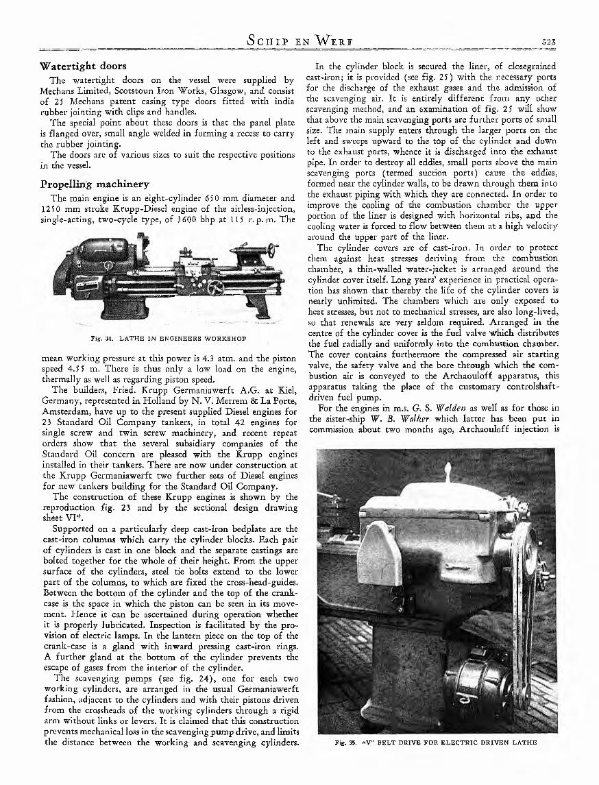
Propelling machineryThe main engine is an eight-cylinder 650 mm diameter and
1250 mm stroke Krupp-Diesel engine of the airless-injection, single-acting, two-cycle type, of 3600 bhp at 115 r. p. m. The
Fig. 34. LATH E IN ENGIN EERS W O R K SH O P
mean working pressure at this power is 4.3 atm. and the piston speed 4.5 5 m. There is thus only a low load on the engine, thermally as well as regarding piston speed.
The builders, Fried. Krupp Germaniawerft A.G. at Kiel, Germany, represented in Holland by N. V. Merrem & La Porte, Amsterdam, have up to the present supplied Diesel engines for 23 Standard Oil Company tankers, in total 42 engines for single screw and twin screw machinery, and recent repeat orders show that the several subsidiary companies of the Standard Oil concern are pleased with the Krupp engines installed in their tankers. There are now under construction at the Krupp Germaniawerft two further sets of Diesel engines for new tankers building for the Standard Oil Company.
The construction of these Krupp engines is shown by the reproduction fig. 23 and by the sectional design drawing sheet V P .
Supported on a particularly deep cast-iron bedplate are the cast-iron columns which carry the cylinder blocks. Each pair of cylinders is cast in one block and the separate castings are bolted together for the whole of their height. From the upper surface of the cylinders, steel tie bolts extend to the lower part of the columns, to which are fixed the cross-head-guides. Between the bottom of the cylinder and the top of the crankcase is the space in which the piston can be seen in its movement. Hence it can be ascertained during operation whether it is properly lubricated. Inspection is facilitated by the provision of electric lamps. In the lantern piece on the top of the crank-case is a gland with inward pressing cast-iron rings. A further gland at the bottom of the cylinder prevents the escape of gases from the interior of the cylinder.
The scavenging pumps (see fig. 24), one for each two working cylinders, are arranged in the usual Germaniawerft fashion, adjacent to the cylinders and with their pistons driven from the crossheads of the working cylinders through a rigid arm without links or levers. It is claimed that this construction prevents mechanical loss in the scavenging pump drive, and limits the distance between the working and scavenging cylinders.
In the cylinder block is secured the liner, of closegrained cast-iron; it is provided (see fig. 25) with the necessary ports for the discharge of the exhaust gases and the admission of the scavenging air. It is entirely different from any other scavenging method, and an examination of fig. 25 w ill show that above the main scavenging ports are further ports of small size. The main supply enters through the larger ports on the left and sweeps upward to the top of the cylinder and down to the exhaust ports, whence it is discharged into the exhaust pipe. In order to destroy all eddies, small ports above the main scavenging ports (termed suction ports) cause the eddies, formed near the cylinder walls, to be drawn through them into the exhaust piping with which they are connected. In order to improve the cooling of the combustion chamber the upper portion of the liner is designed with horizontal ribs, and the cooling water is forced to flow between them at a high velocity around the upper part of the liner.
The cylinder covers are of cast-iron. In order to protect them against heat stresses deriving from the combustion chamber, a thin-walled water-jacket is arranged around the cylinder cover itself. Long years’ experience in practical operation has shown that thereby the life of the cylinder covers is nearly unlimited. The chambers which are only exposed to heat stresses, but not to mechanical stresses, are also long-lived, so that renewals are very seldom required. Arranged in the centre of the cylinder cover is the fuel valve which distributes the fuel radially and uniformly into the combustion chamber. The cover contains furthermore the compressed air starting valve, the safety valve and the bore through which the combustion air is conveyed to the Archaouloff apparatus, this apparatus taking the place of the customary controlshaft- driven fuel pump.
For the engines in m.s. G. S. W alden■ as well as for those in the sister-ship W. B. Walker which latter has been put in commission about two months ago, Archaouloff injection is
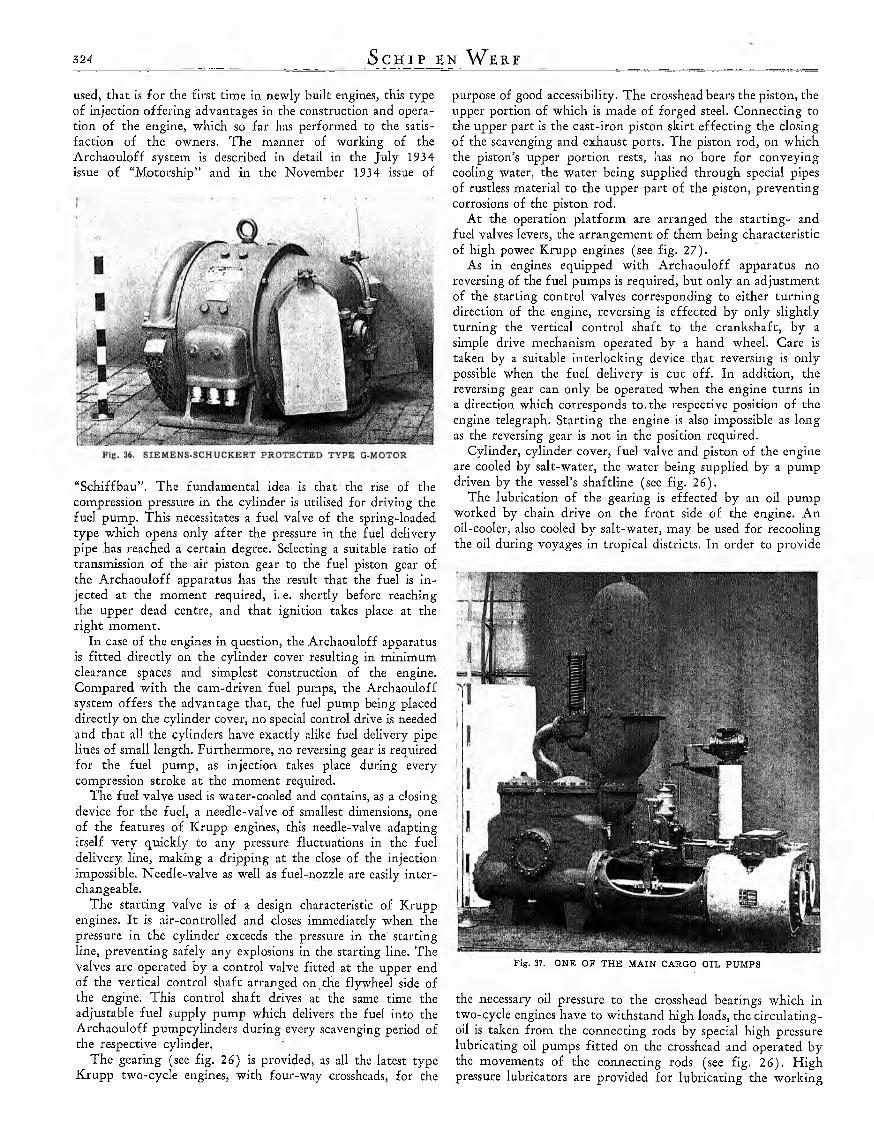
used, that is for the first time in newly built engines, this type of injection offering advantages in the construction and operation of the engine, which so far has performed to the satisfaction of the owners. The manner of working of the Archaouloff system is described in detail in the Ju ly 1934 issue of “Motorship” and in the November 1934 issue of
“Schiffbau”. The fundamental idea is that the rise of the compression pressure in the cylinder is utilised for driving the fuel pump. This necessitates a fuel valve of the spring-loaded type which opens only after the pressure in the fuel delivery pipe has reached a certain degree. Selecting a suitable ratio of transmission of the air piston gear to the fuel piston gear of the Archaouloff apparatus has the result that the fuel is injected at the moment required, i. e. shortly before reaching the upper dead centre, and that ignition takes place at the right moment.
In case of the engines in question, the Archaouloff apparatus is fitted directly on the cylinder cover resulting in minimum clearance spaces and simplest construction of the engine. Compared with the cam-driven fuel pumps, the Archaouloff system offers the advantage that, the fuel pump being placed directly on the cylinder cover, no special control drive is needed and that all the cylinders have exactly alike fuel delivery pipe lines of small length. Furthermore, no reversing gear is required for the fuel pump, as injection takes place during every compression stroke at the moment required.
The fuel valve used is water-cooled and contains, as a closing device for the fuel, a needle-valve of smallest dimensions, one of the features of Krupp engines, this needle-valve adapting itself very quickly to any pressure fluctuations in the fuel delivery line, making a dripping at the close of the injection impossible. Needle-valve as well as fuel-nozzle are easily interchangeable.
The starting valve is of a design characteristic of Krupp engines. It is air-controlled and closes immediately when the pressure in the cylinder exceeds the pressure in the' starting line, preventing safely any explosions in the starting line. The valves are operated by a control valve fitted at the upper end of the vertical control shaft arranged on,the flywheel side of the engine. This control shaft drives at the same time the adjustable fuel supply pump which delivers the fuel into the Archaouloff pumpcylinders during every scayenging period of the respective cylinder.
The gearing (see fig. 26) is provided, as all the latest type Krupp two-cycle engines, with four-way crossheads, for the
purpose of good accessibility. The crosshead bears the piston, the upper portion of which is made of forged steel. Connecting to the upper part is the cast-iron piston skirt effecting the closing of the scavenging and exhaust ports. The piston rod, on which the piston’s upper portion rests, has no bore for conveying cooling water, the water being supplied through special pipes of rustless material to the upper part of the piston, preventing corrosions of the piston rod.
At the operation platform are arranged the starting- and fuel valves levers, the arrangement of them being characteristic of high power Krupp engines (see fig. 27).
As in engines equipped with Archaouloff apparatus no reversing of the fuel pumps is required, but only an adjustment of the starting control valves corresponding to either turning direction of the engine, reversing is effected by only slightly turning the vertical control shaft to the crankshaft, by a simple drive mechanism operated by a hand wheel. Care is taken by a suitable interlocking device that reversing is only possible when the fuel delivery is cut off. In addition, the reversing gear can only be operated when the engine turns in a direction which corresponds to.the respective position of the engine telegraph. Starting the engine is also impossible as long as the reversing gear is not in the position required.
Cylinder, cylinder cover, fuel valve and piston of the engine are cooled by salt-water, the water being supplied by a pump driven by the vessel’s shaftline (see fig. 26).
The lubrication of the gearing is effected by an oil pump worked by chain drive on the front side of the engine. An oil-cooler, also cooled by salt-water, may be used for recooling the oil during voyages in tropical districts. In order to provide
Fig. 37. ONE OF THE M AIN CARGO O IL PU M PS
the necessary oil pressure to the crosshead bearings which in two-cycle engines have to withstand high loads, the circulating- oil is taken from the connecting rods by special high pressure lubricating oil pumps fitted on the crosshead and operated by the movements of the connecting rods (see fig. 26). High pressure lubricators are provided for lubricating the working

pistons with cylinder lubricating oil. The Archaouloff pumps are lubricated with a suitable heat-resisting grease, by means of special lubrication pumps.
Two starting air vessels, each having a capacity of 14 cub. m and a working pressure of 24 kg per sq. cm, are located in the engine room to supply the required starting air for the main motor. The general arrangement of the engine and boiler room is shown on sheet VII*.
Thorough tests on the test-bed and particularly the experience on m.s. W. B. W alker have shown that the engine is meeting any requirements of the heavy duty service on oil tankers. So it has been possible to overload the 3600 bhp engine up to 4400 bhp at 120 r. p. m. without showing any mechanical trouble and without impairing the good combustion. The manoeuvring qualities of the engine have also proved to be absolutely satisfactory.
PropellerThe propeller has a diameter of 5 m and a developed blade
surface of 7.14 sq. m and has been constructed and supplied by the Atlas Werke A.G. Bremen to the specifications of the Nederlandsch Scheepsbouwkundig Proefstation, Wagen ingen. It is a built-up four-bladed propeller with cast-iron boss and blades of high-grade Atlas manganese bronze of at least 46 kg per sq. mm tensile strength made in accordance with the Rules of Lloyd’s Register of Shipping. Weight of the propeller 10,700 kg.
Steam supplying plantThe exhaust gases of the main motor are led to a horizontal
tubular exhaust gas boiler designed and made by the Rotterdam Drydock Co. and situated in a separate boiler room at about tween deck level. This boiler has a heating surface of 130 sq. m and is capabel of withstanding a boiler pressure of 14.06 kg per sq. cm. The exhaust gas inlet box is provided with a built in tubular steam dryer, and in the outlet box a Liesco high pressure economiser is fitted of ample dimensions to heat the feed water from 104° F. to about 275° F.
The exhaust gases of the Diesel engine enter in the “Turbulo” spark catcher with silencer (see fig. 30) and then flow through the separating canal, during which process the combustinal residues by means of the centrifugal force are led outside into a collecting chamber beyond the gas stream by means of special guide blades. The gases are pressed off to the inside, all in a whirl, thus forming a specially elastic cushion, which will serve to elastically catch and gently annihilate all knocks emanating from the engine. Thus the gas flow will be evenly directed and all exhaust noises absolutely eliminated.
The loss of pressure in the spark catcher is but small. It amounts to about 120— 150 mm head of water, that is not more than with ordinary silencers.
In normal service, the exhaust gas boiler has to work in conjunction with two single ended marine type Scotch boilers, also made by the Rotterdam Drydock Co., each having a heating surface of 225 sq. m and 14.06 kg per sq. cm boiler pressure. For this purposes, the steam and feed water lines interconnect the three boilers in such a way that the exhaust gas boiler is acting simply as a circulator for the two auxiliary boilers, thus promoting an economic steam production for the auxiliaries in the engine room, the cargo handling plant and the deck machinery.
The furnaces — 3 per boiler — are of the “Morison” patent corrugated type and manufactured by The Broomside Boiler
Works Co. Ltd., Camp Road, Motherwell, Scotland. They are of Siemens acid mild steel and machine rolled in one operation: made interchangeable, and on the Stephen Gourlay back end withdrawable plan and equipped with furnace fronts for burning oil fuel under forced draught.
A Todd automatic “High-Low” fuel oil installation is fitted in the boiler room (see fig. 28 and 29), consisting of two electric driven main burner fuel oil pumps and two electric driven pilot burner fuel oil pumps with the necessary fuel oil heaters and suction and discharge filters.
The system consists of a suitable combination of burners, valves, oil and air controls and safety devices, to provide for
F ig . 38. P R E S S U R E V A C U U M V A L V E
the automatic operation of the oil burning system in all functions with the exception of the initial ignition, which remains manual.
The application of the system to the oil burning installation provides an automatic operation of the burners which may be regulated to maintain a steady steam pressure upon the boilers, within adjustable limits, up to a maximum of 1 kg per sq. cm.
It further provides the necessary safety feature to prevent the discharge of oil into the furnaces if there is no flame present to ignite same and, in addition, gives warning of the failure of the particular burner to ignite or of its extinguishment, should this occur.
The system requires the maintenance of a source of oil supply at the correct pressure provided by an electric driven oil pump which is under the control of the steam pressure.
This pump supplies oil to the main burners on all furnaces and is indirectly controlled from a switch operated by the steam pressure which also simultaneously controls the operation of the electrically driven forced draught fans.
This section of the system is solely concerned with the supply of the fuel oil and air necessary to meet the requirements of the steam output of the boilers.
An independent source of oil supply, not under control of the boiler pressure, is provided by an auxiliary electrically driven pump the duty of which is to maintain oil at the required pressure to maintain a constant pilot flame in an

3 2 6 S c h i p e n W e e f
auxiliary burner arranged adjacent to the main burner in each furnace. This burner is designed to burn only sufficient oil to provide a permanent flame for the ignition of the main burner when the oil is automatically switched on same by the failing steam pressure. The volume of flame developed by the auxiliary or pilot burner is so low that no steam pressure is generated thereby in the boiler, and the oil pump is non-automatic in operation, being operated by a manually controlled switch.
Fig. 39. PR E SSU R E VACUUM VALVE
The combustion safety feature is provided by an independent control system, the basis of which is centered in the Protectoglow Unit.
This device operates upon the principle that a flame is a conductor of electricity to an extent sufficient to operate an electrical valve.
This valve is embodied in the grid-glow tube which, in conjunction with an electrode and a suitable housing, forms the sensitive member of the combustion safety system.
The presence of a flame in the furnace in contact with the electrode of the protectoglow provident a circuit to ground for a current potential that is normally present therein when the system is in operation, and this current flow is detected by the grid-glow tube or valve, which instantly responds to the condition prevailing.
The protectoglow is connected to a special relay, known as the glow-relay, which amplifies the feeble current received from the grid-glow tube,: and makes use of same to control a heavy current capable of exerting mechanical functions.
It is this heavier current which, indirectly under control of the flame, effects the opening and closing of solenoid operated oil valves, and the operating of warning devices.
The solenoid valves are installed in the oil line feeding each main and pilot burner where they act solely to permit or
prevent the flow of oil to the burner in accordance with the flame conditions prevailing; this, if the pilot flame is slight the valves are maintained in the open position but, should the flame become extinguished for any reason, both main and pilot valves will close, and will not re-open until a flame is re-established.
The insertion of visible or audible warning signels to provide local or remote indication of flame failure, is accomplished by means of lights or bells or combinations of both, which may be wired into a special circuit provided in the relay.
The operation of the combustion safety control system requires that a supply of 110 volt A. C. 60 cycle single phase current be available, and this is provided from a rotary converter which converts the D. C. supply from the ship’s generators into A. C. of the required voltage and frequency. This machine requires to be run continuously during the operation of the system, and is manually started and stopped as required.
The entire system seeks to provide automatic operation of the oil burning plant to an extent that is limited only by the fallibility of mechanical and electrical devices and, in this eventuality, means are provided to give warning that a failure from developing into a hazard, thus eliminating the necessity of human intervention except to initiate operation or restore same after failure.
The electric switches, fuses and control apparatus for the fuel oil pumps are combined in boxes, which are located in places easy of success. Fuel oil will be drawn from daily service fuel oil tanks, situated in a seperate room aft of the auxiliary boilers. Two electric driven forced draught fans will draw the air from above the boiler tops and discharge by way of a multi- tubular air heater, which is fitted in the upper part of the uptake, to the air directors in the furnace fronts.
To ensure full dry steam being admitted to the cargo pumps in the main and forward pump rooms, the auxiliary boilers are provided with uptake superheaters in which the steam is superheated to a moderate extent.
There is a spark arrestor at the top of the smoke funnel, which is also fitted inside the outer funnel. The outer funnel is semi-closed at the top and is provided with a Venetian blind, operated from the fidley deck, to regulate the ventilation for the boiler room.
AuxiliariesOne Atlas Werke vertical simplex boiler feed pump 300 X
210 X 600 mm and 1 Atlas Werke vertical simplex feed pump for waste gas boiler 120 X 80 X 200 mm, output 2.3 cub. m/h are erected in the boiler room to deal with the required feed water from the hotwell tank through a discharge filter and a discharge feed water heater of 10 sq. m heating surface. The feedwater surface heater for heating the feedwater to abt. 100° C. with the exhaust steam of the auxiliaries, and the feedwater purifier with cloth filter fitted are provided with by-pass valves and can be cut out of the system at any time. They have been made by Atlas Werke, of Bremen.
In the boiler room is further installed an auxiliary condenser made by the Rotterdam Drydock Co. having a cooling surface of 209 sq. m and capable of condensating the exhaust steam of all steam auxiliaries. The vacuum in this condenser will be created by means of an Atlas Werke steam driven horizontal Duplex condensate pump 150 X 150 X DO and an air ejector with condenser, all of these units having to carry the condensate to the hotwell tank.
An Atlas Werke evaporator having a capacity of 12 tons of

Fig. 40. L E AVIN G FOR T R IA LS
water per 24 hours, and a ditto distiller with an output of 2.7 tons of water per 24 hours, are also situated in the boiler room.
For the purpose of cleaning the cargo oil tanks with hot water, in addition to steam cleaning, there is a special heater installed, having 28 sq. m heating surface, and capable of dealing with 104 tons of seawater per hour at a temperature of 180° F. The hot water thus obtained will be discharged into the cargo tanks by means of special sprayer pipes, known as the Butterworth device.
The division bulkhead between the engine room and stokehold is provided with three passage openings, situated at different levels, and corresponding to the main gratings in the engine room. These openings made be closed by hinged gastight doors, swinging inside the engine room, thus assuring an easy escape from the stokehold in case of fire.
In addition to the steam fire extinguishing plant in the boiler room, there is a battery of C 0 2 flasks erected in the steering engine room aft of the boiler room. A pipe line from these flasks is led down to- the boiler room and the shut off valves fitted in this pipe line may be operated either from or outside the stokehold.
The cooling water for the condenser w ill be supplied by a steam driven Atlas Werke condenser circulating centrifugal pump for an output of 510 cub. m/h, driven by enclosed type steam engine, 240 X 150 mm cyl. diameter, running at 375 r. p. m. erected in the engine room, and further a steam driven duplex cooling water pump is fitted as standby to the main shaft driven cooling water pumps for the main engine. A steam driven Atlas Werke vertical simplex feed pump 300 X 210 X 600 mm, output 11,5 cub. m/h, is also located in the engine room as stand-by to those situated in the boiler room.
For sanitary and drinking water purposes 2 Atlas Werke vertical simplex drinking water and sanitary pumps cyl. dim. 140 X 13 5 X 200 mm, output 19 cub. m/h each, are installed in the engine room, and a steam driven Atlas Werke vertical simplex General service pump cyl. dim. 390 X 260 X 450 mm, output 104 cub. m/h. The pump also serves the Butterworth system for cleaning the cargo tanks and has to work against 12.65 atm. pressure through the Atlas Werke seawater heater for the Butterworth system, for heating 104 cub. m/h of seawater to abt. 82° C. with steam of 10.6 atm. A ll pumps for water have pump cylinders of high-grade bronze.
Besides the lubricating oil pump driven from the main shaft, there is also an auxiliary lubricating oil pump of Atlas Werke make 170 X 200 X 52 5 mm output 42 cub. m/h. Before entering the main engine, the lubricating oil is cooled in a multitubular oil cooler having a cooling surface of 3 5 sq. m.
The dirty lubricating oil will be pumped into a dirty oil tank, having a capacity of 5 cub. m and from this tank led to a purifier, which will carry the cleaned oil to a clean lubricating oil tank.
Large storage tanks for cylinder oil, lubricating oil and compressor oil are erected in a separate space on the tween deck.
Two Atlas Werke vertical duplex fuel oil transfer pumps 190 X 160 X 250 mm, output 34 cub. m/h each are erected at the engine room floor level, which enable the fuel oil to be pumped from one bunker into the other, as also from the bunker into the daily service tanks etc.
The cleansing of the diesel oil from all mechanical admixtures as undissolved asphalt, grains of sand, fibrous matter and water is done in a “Turbulo” Oil Finefilter.
The “Turbulo” Fuel Oil Finefilter (see fig. 31 and 32) consists of a cascade filter of special construction, the chambers of

Fig. 41. ON T R IA L S
which serve to separate the heavy admixtures of oil and water, and of two interchangeableclotch filters, which are alwaysworked alternately, i. e. one being shut off for cleaning purposes. The clotch filter catches all those impurities of the oil which have not been separated by the gravity action of the cascade filter.
The changing of the clotch filters is done in a few seconds while the filter is in service.
A three-way cock with by-pass pipeline in the oil supply piping serves to enable the whole fine filter plant to be shut off for thorough cleaning of the cascade about every six months while in port.
By heating the oil the purifying process is greatly accelerated and improved.
The temperature of the oil running off may be observed from the thermometer in the outlet pipeline of the finefilter.
Two drip proof generators of Messrs. Siemens Schuckert make,
each of 30 kW at 110 Volts D.C. will supply the necessary current for the electric plant of the whole ship. Each generator is driven by a forced lubricated Atlas Werke compound steam engine and one of these engines also drives a Krupp’s emergency air compressor.
An independent twostage twin air compressor (makers: Germaniawerft, Kiel), output 212 cub. ft./h of air at a final pressure of 28 atm., is directly coupled to a “Roland” enclosed steam engine, made by the Atlas Werke (see fig 33), cylinder diameter 260 and 440 X 200 mm, 350 r. p. m. The engine is provided with a governor adjustable by hand.
These engines will supply the necessary compressed air for starting and manoeuvring purposes.
The firm of Schaffer & Budenberg have delivered all the manometers for the vessel, including the groups of self registering manometers.

For easy handling of the heavy parts of the main engine, a 5 tons overhead travelling crane is fitted in the fidley.
To enable the engineers to carry out small repairs on board, a workshop is placed on the tween deck, containing a large and small lathe, shaper, drilling machine and grindstone, all of which are driven by their own electric motor.
Fig. 42. SPEED PO W E R CURVE N O RM AL FORM ON PO L PE R R Y M ILE. DATE 22-6-’35
ARC-FO RM ON P O L P E R R Y M ILE. D ATE 19-8-’35
The lathe installed in the workshop of this ship has been supplied by the well-known metal and wood working machin- ery-dealers and pumping plants Spliethoff, Beeuwltes & Co. Ltd. of Rotterdam, being u. o. representatives of the makers of this machine, viz. “Union-Werk”, Mittweida i. Sa., Germany. Some characteristic features of this All-Geared Single Pulley Head High Speed Lathe ME 5 are given as follows:
It has a swing over bed of about 27Va" and a distance between centres of approximately 5 feet (see fig. 34).
The machine, being a product of first class workmanship, is of modern construction and practised allover; it has been constructed in accordance with the DIN forms in a modern machine plant, so that it will meet the highest requirements.
The Vee-bed is of rigid box construction.The all-geared fast headstock has 18 various main spindle
speeds; a “twin disc” clutch for right and left motion and an equipment to cut coarse threads.
By means of the combined Feed- and Universal Quick- Change Screw-cutting Gear bov 70 various W. W ., metric and module pitches can be cut.
The machine had leadscrew and feed rod; a separate rod for starting and stopping at any predetermined point and further automatic feed-stop in either direction.
As may be seen from fig. 3 5 the machinery is electrically driven by means of double Y-belts in connection with an electric motor mounted adjustably on a motor-plate bolted down to the cabinet leg. Motor and further electrical equipment have been supplied in tropical outfit.
The lathe in general has been constructed by the makers in accordance with American requirements, so that the engineering staff have the disposal of a modern High Speed Machine, on which repair-jobs during voyage can be satisfactorily finished.
The following is a list of electric motors and generators delivered by the firm of Siemens-Schuckert.
1. Two compound-direct current generators GV 283,30 kW, 110 Volts, running at 375 r. p.m ., coupled direct to a steam engine.
2. A couple of motors type G, protected type (see fig. 36).3. One motor type VG.4. One self-priming Elmo-waterpump type LPW 26.5. Thirty-six electric fans.6. One search-light, type GI 3 5 St., with 2000 W att lamp,
controlled from bridge.7. Various lighting ornamente such as cabin reading lamps,
and deck lamps.The electric installation was done by the firm of Mijnssen &
Co. of Amsterdam.
Cargo pumping plantIn the main pump room (see sheets VI11* and IX *), there are
erected two steam driven horizontal duplex main cargo oil pumps (see fig. 37), each having a capacity of 470 tons per hour, to deal with the cargo in the main cargo tanks. Besides these pumps, there are two steam driven horizontal duplex cargo oil pumps, located in separate rooms at summer tank deck level, for handling the cargo in the summer tanks. Each of these pumps has a capacity of 220 tons per hour.
For draining and bilge water purposes there are further installed, one steam driven Atlas Werke vertical duplex drain pump, 320 X 220 X 300 mm, output 90 cub. m per hour, and one steam driven horizontal duplex bilge pump.
The forward pump room (see sheets X*, XI* and XU*) contains one steam driven horizontal duplex main cargo oil pump, one steam driven horizontal duplex summer tank pump, both of the same capacity as the respective pumps in the main pump room, and further, steam driven duplex drain pump, bilge pump, ballast pump and fuel oil transfer pump, all of which
have been supplied by Atlas Werke, Bremen, to design developed as a result of cooperation between the Standard Shipping Co. and themselves.
Particulars of these pumps of Atlas Werke make are as follows:
Six horizontal duplex cargo oil pumps on board viz. 3 pumps 480 X 380 X 3^0 mm cyl. dim., output 470 cub. m/h each at

3 8 DS/inin., and 3 pumps for the summer tanks, 420 X 300 X 450 rmm, output 220 cub. m/h each at 35 DS/min.
The pumps are strongly built for delivering up to a total pressure of 17.6 atm. and are equipped with Mason governors.
The pump valves are disc valves of approved special design. Large suction and pressure air chambers and by-pass valves ensure a smooth service, free of all trouble.
Two horizontal duplex pumps of 150 X 1 50 X 150 mm, serving as bilge pumps for the pump rooms, output 40 cub. m/h each, w ith all bronze pump cylinders.
The cargo pipe lines in the tanks (see sheet X III*), pump rooms and on deck are provided with the requisite valves enabling different kinds of liquid cargo to be handled at the same time.
A steam smothering and fire extinguishing pipe line is fitted along the deck, with valved connections to the pump rooms and all cargo tanks.
To balance the partial vacuum or pressure above atmospheric which results from light gasifying liquids in the storage-tanks of tankers during the transport by cooling-down or heating or during the drawing off or the filling, the vacuum-pressure- valves of the Gasometer-Wilke A.G., Braunschweig, Germany, are fitted (see fig. 3 8 and 39).
The vacuum-pressure-valves have disc-valves, 2 of them are adjusted for 50 mm W C of partial vacuum and 2 for 500 mm W C of pressure above atmospheric.
If the partial vacuum in the tank rises above 5 0 mm W C , the discs of the vacuum-pressure-valves will be lifted by the atmosphere. The atmosphere enters the tank until the partial vacuum w ill have reached 5 0 mm WC again. In the same w ay the pressure valves open as soon as the pressure above atmospheric in the tanks rises above 5 00 mm WC.
No less than 7 fixed "Dockyard” patent gas-devourers of the 4V2" size, and one portable 12'' devourer, w ill be on board to make the pump rooms, cargo tanks etc. gas-free and the enormous suction capacity of these devourers w ill ensure the gas-freeing of the vessel in the least possible time.
TrialsThe speed trials took place over the measured mile course at
Polperro, in the neighbourhood of. Plymouth where a sister ship of the G. S. W alden carried out progressive trials under practical! y similar conditions as recently as June 22nd, 193 5 (see fig. 40 and 41 ).
It w ill be of interest to note that these two vessels, apart from hull form, are almost identical, in fact the main motors were duplicates in every respect and constructed by the same firm.
The sister ship is acknowledged to be an efficient vessel of normal form derived from the results of tank experiments, so that the data given represents an interesting comparison between two first class tankers, differing prim arily in hull form.
Curves are given in fig. 42, 43 and 44 which show in a graphical manner the remarkable degree of efficiency attained by the G. S. W ald en ; at the designed speed of 12 V2 knots the admiralty coefficient based on B. H. P. is approaching the figure of 470, whilst the power is about 13 % less than the normal formed vessel, so the Owners are to be congratulated upon having added to their fleet what must surely be one of the most efficient tankers afloat. The builders therefore gain a bonus from the owners as a reward for their in itiative in establishing the results predicted from their research work.
The arc-form vessel G. S. W alden is a fu ll half knot better than the normal form under identical conditions of this placement, weather and horsepower.
A representative company attended the trials both in the North Sea during stormy weather and at Polperro under good conditions of .weather and sea, where under these conditions the steadiness of the vessel and her machinery were favourably commented upon.
Index to A dvertisersAarst, Gieterij, Technisch Bur. A. van, W eert (H oll.) (x ix ) Atlas-W erke A. G., Bremen (x ix )Bakker & Co., N. V. Machinefabriek, IJzer-, Staal- en
Metaalgieterij v/h., R idderkerk (H olland) (x ix )Beer, P. de, Rotterdam (x x )Birmingham Battery & Metal Company Ltd., The, Selly Oak,
Birmingham (ix )“Bolnes” v/h. J . H. van Cappellen, N . V. Machinefabriek,
Bolnes (H olland) (cover)Brandt & Co. Ltd., Ed., Eeckeren (xvn)Brown Bros & Co. Ltd., Edinburgh (x ix )Brown, Lenox & Co. Ltd., Pontypridd (S. W ales) (x ) Burghout & Co., Technisch Bureau, The Hague (xvm ) Compositieverven, Fabriek van, Delft (H olland) (xxn ) Crossley Motoren, N. V., The Hague (ix )Cupoline, The Hague (x x n )Dahlmann, N. V. Technisch Bureau van G. L., Rotterdam
( i x and X V I )Delftsche Machinefabriek &: Reparatie-Inrichting, N. V.,
Delft (Holland) (xxn )Demag Aktiengesellschaft, Duisburg (G erm any) (xvi) Deutsche W erft, A. G., Hamburg (xvn)Deutz, N. V. Motorenfabriek, Rotterdam (x x )Doorman, Techn. Handelsbureau L. R ., The Hague (xvm ) Dordrecht, Havenbedrijf der Gemeente (Dordrecht M unici
pality (cover)D ijk, Fr. van, Rotterdam (x x i)Dyserinck Zonen, N. V. Oliehandel Van, Haarlem (x iv) Fennia, N. V. Handelmaatschappij, The Hague (vm )Gaade v/h. Aamij, Handelsbureau, The Hague (xxn )Geveke & Co.’s Technisch Bureau, N. V., Amsterdam (iv) Giessen’s W erktuigenfabriek, C. van der, Krimpen a/d.
IJssel (H olland) (xvm )Haarlemsche Kunstbrons, Metaalgieterij en Draaierij
F. Roessingh van Iterson, Haarlem (x )Hagen, A. G., Gottfried, Koln-Kalk (G erm any) (vm )

Handelscompagnie, N. V., Rotterdam (x)Havenbedrijf der Gemeente Dordrecht (Dordrecht Munici
pality) (cover)Havenbedrijf der Gemeente Rotterdam (Rotterdam Munici
pality) (cover)Heyme Vis & Zoonen, N. V., Zaandam (Holland) (xiv) Hoek’s Machine- en Zuurstoffabriek, N. V. W. A., Schie
dam (Holland) ( x x i i )
“Holland” Ltd., Hendrik-Ido-Ambacht (Holland) ( x v i i )
Hoogerwerff & Co., Kinderdijk and Vlaardingen (Holl.) (iv) Houttuin’s Machinefabriek, Utrecht ( x v i i )
Iffa-Minimax, N. V., Amsterdam (cover)Ingenieurskantoor voor Scheepsbouw, N. V., The Hague (v) Internationale Mineralen Cy., N. V., The Hague ( x x i i )
Internationale Nautische Handel Maatschappij, N .Y ., The Hague (v and ix)
Isherwood & Co. Ltd., Sir Joseph W., London, N. York (ix ) Kaumanns & Co., N. V. Technisch Bureau v/h., The Hague,
Bandoeng (xvi)Kerger & Co., Rotterdam (xx)Keyser & Mackay, Amsterdam, Rotterdam, Groningen
(cover)Koloniale Petroleum Verkoopmaatsch., N. V., Batavia-C. (n) Koopman, N. Y. Machinefabriek v/h. H. J., Dordrecht
(Holland) (xvin)Koppejan, Ir. A. C., The Hague (xvi)Kramer, W. J., Haarlem (xvi)Krieger (Ruhrstahl A. G .), Stahlwerk, Düsseldorf-Oberkassel
(xvi)Krupp A. G., Fried., Essen (xv)Krupp-Dieselmotorenbau Germaniawerft, Kiel (v)Lessen & Punt, Van, Rotterdam ( x v i i )
Maas” v/h. Vennix & Bertou, N. V. Motorenfabriek “De, Rotterdam ( x x i i )
Martinit N. V., Amsterdam (iv)Merrem & La Porte N .V . (Fried. Krupp A. G., Essen),
Amsterdam (v and xv)Mijnssen & Co. N. V., Amsterdam ( x x i i )
Nederl. Koloniale Petroleum Mij., N. V-, The Hague (in )
Nekef (Nederlandsche Kjellberg Electroden Fabriek), N. V., Amsterdam (cover)
Octrooibur. Vriesendorp & Gaade, N. V., The Hague (xvin) Osten & Kreisinger, U. v. d., Hamburg 21 (iv)Peiffer, N. V., Rotterdam (cover)Press- und Walzwerk A. G., Düsseldorf-Reisholz (xviir) Renold Chains Ltd., Amsterdam (xiv)Rietschoten & Houwens’ Electriciteits-Maatschappij N. V.,
Van, Rotterdam ( v i i i )
Rotterdam Drydock Comp., The, Rotterdam (vi, vu and xv) Rotterdam, Havenbedrijf der Gemeente (Rotterdam Munici
pality) (cover)Ruhrstahl Aktiengesellschaft, Düsseldorf-Oberkassel (xvi) Schaefer, Hermann, The Hague (xvi)Schaffer & Budenberg, N. V., The Hague (xx)Schmitt, Fa., Rotterdam (cover)Simplus Brandbluschapparaten N. V., Dordrecht (Holland)
(xxn)Smit, N. V. Fabriek van Klinknagels en Schroefbouten v/h.
Joh., Slikkerveer (Holland) ( x x i i )
Smit & Co.’s Transformatorenfabriek N. V., Willem, N ijmegen (xxi)
Spliethoff, Beeuwkes & Co. Ltd., Rotterdam (xxi)Stephen Adam, N.V. Techn. Bureau, The Hague (ix, x,
x ix and xx)Stone & Company Ltd., J., London (v)Stork & Co. N. V., Machinefabr. Gebrs., Hengelo (Holl.) (i) Todd Oil Burners Ltd., London E. C. 3 (xx)“Tubus” Handel-Maatschappij N. V., Hendrik-Ido-Ambacht
(Holland) ( x x i i )
Uittenbogaart & P. de Beer, N .V . Technisch Bureau v/h. F. W., Rotterdam (xvn)
Vroom & Dreesmann, N. V., Rotterdam (cover)Walker & Co. Ltd., James, Woking, Rotterdam (cover) Watson-Warner (Pumps) Ltd., Newcastle upon Tyne 1 (xxi) Werf, N. V. Scheepswerf Gebrs. van der, Deest (Holl.) (xvn) West Bromwich Spring Co. Ltd., The, West Bromwich (xx) Wit, W. C. & K. de (Atlas-Werke A. G., Bremen), Amster
dam (xix)
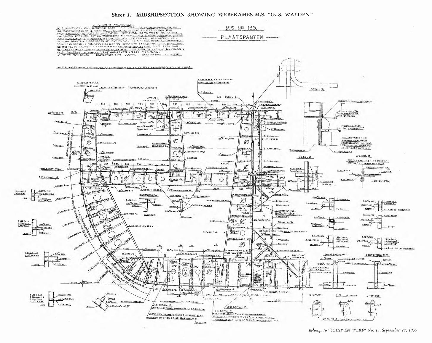
\ J O Q K P L A A T S P A H T E N \N Z Q W‘ E.t?TANK T .P.V. O.D.PW BH&SftH O T T E N Z lE f & E .W . O .p.P U lR R & S C M Q TTEN N« I S S O ^ S
0? r»LAAT SPANT.D Q QR6N g.D ET.PW .bR M .Ci,
PLAATS PAN T 6 ^ -6 5 t u 6 S ------------------------------------------ U N C ,5 fc fiL K t.N tg 5 0 »a o taoo*ao»t*
2. IE pet Ail CtUSTAILSI
UK. ‘DETAIL C. iZETm n»s fjgjK SLWEK HOgKfiTftLtNa-at%nwfi: *lOOHOc» tp5
LM HOe.K j.f RPl.boVendex.
jÆitr/M HRgMp/
DE7.F. C O N S TR U C TIE IN H E T
I AUQEM&eh TOETSPRMjErtVjAAff HOSK5ÏALE.M AAN KMIEËU
i AgM E K S N t .f.v.l r no &n a an.v e VtrOQv?a».jDE f b C M Q T .
3.150xl0wiVW.S5affi
3._.î.xsoiaar_Ji,yaJS2*ivyt6j&*6l,y Nag! £a%! me: g<£>W.S.M®
aUSttg&gk;^5-JL15Q»1So»m ^£iâJÏL_ J . 6 3 a ■
DETAIL fl,ANC56taj<EN Lg5oQ»n E SSaSQjili V/O&P OQgaGHIP,\aaSRÄSA.MtaDEWLANq&fcflHnf
p l a a t balkMANfii.goQnaBim!£% NW:L/p P LA A TR A LK .
_£IE PE.TA1L M■i‘ WAasa
.az Nnc: **p. i-[>-IEO»yS»l I .WA.B6.fi
SOQgfeNK. D--QSPANTJN X’ TANK, t aooiSvHj (. £bo«9oMii’-safeöwiMUfn..M-L SCHOT. ML SCHOT En TBUKKWÂnd
£2.%NHC6mT}. L LEO»flpy |L.t*oo"SP»n>
LtS°»30»n C-ZBOtSo» teLàS5*ao*UL-
ISO «J j
I r - — *--------------------Lgg -% NAC‘ ✓ S
VffnNC. /*M-\..S>CHOT.EikA&HgLgyp.MtncwKUN AAN-&61DE WtnBwaa%NRiy. y
-MSo»?5«tQ
PU5.TÜLM L.fe C H O T
h&ZÇ&i'e -XAJkftl >k. H i îôsb • raâsïiZvî ift, ijôjîï*! l â â t S _ J L
22%NBC'AJfD-£Jllfe> <*•»■** 8'vu::
5UPP0RT5ÜPP0KT.jvwtH; t. tscHaani1»,
.P U S P A N T.
CATacin L>u£tlem ALLSSN S.fo. IN
J ÆUÆ PiAfflaaMPJSa.ÿ’ rtiSûHfato w,‘«jase ©
IfeAKliLUNft,Aa&làLUHj -US25S&5ÆML
jlN HUI.0 KS'Ifa tjlRC U6» s-yiso»?EL j OQKSQxia -L5.Qp"flo=J3j, 1 iOQnaoKis „Li’b/z.« v»,'.aÇ? 0Tg.î?Sftn&50
■ƒ- 6aaEM&6ANTgN C If w fa."» /,.% t,A\ çp-LZ.IL DETAIL. E. dgSligOHlLQP V/E&SP;
PÇTfoPftNT.
<£HE DETAIL X)7. iE -DE.TAIL F
g..SV5VS»-6Q-6‘t-6S-?M'f&- 7 s o » ia w . B . s s . y . o p v s g j io 'p » i s t Ei-i,
i M à 6 - s y - 6 y - 6 B - y 6 - y ^ a l b thoo^ s h e d e . a -
■JER&TjVinCO C. Qoo»; O P V jE B E iP A N T S O - S i \ CAT EN Moonr •Q00R6 «N6 PftQF'ET.LL n
DE. PLA L OU*. ' c. Oî* ME'»? V C i t'iGS. > •*
A T & î » A N T E N . Z U N C E T E 'E V rr -T O & c. Z . i E M N A A T g V .QO .r
ïsSbb”KS6 '/&/' Ki-LINEf?
KOOJUttEL ■ ÎSOTC 'TSE.GF.L'JK HOUtiEM MgTTPVlMV E.1»-* Z.'JWGiK.Mg.TEW OP HA' T
WA6EL6ATSN MQOtg\K V f S g a V l »5* K L g .m ? .V E ~ ALLE'.
6TUUl»ao
E DUMSTEg.?.W v/o VA CÆK a.T RV.~e.tA . ’PLAAT. ALLE. '»Hft&ELO
~ g.tA . E N M A V i E T _
■ ■TU-&&CHS.M •ftuBBSLE SsT/a Mah__A OEJTE.N y.’JN KQPKA&t.Lfe.
Ç.-Q. îyiiL' ë f f i g o iwÀÂwka»-ATS.N OPRUiWEH TQ'HÔ-EKÆTALJLH TJE T»L A ATag.HALMS.\H 'DE KNÆÉNEM N/RANGEN TU&&C.HEW HQEKfbTALg.U ..TE&EN HET 0-T>..M.L .feCHOT AAM PE. KÛOVCZIJDE . WELKE. AAN ftEiOE KANTEN n/ET7ZCiNWgN MORTEN DE PLAATS» VAU
LANS66PANTEN VANDE VfLOER OP TE .__L\T 5~N.EN. ...XAgja t HE *lULTOKV<EMQF \/UL£>TR\PPE.N TE MAWEN WAAR AANC.F.&EVEN POOR \X ?,ETEEKENT I &PUT6, IS&ETEEKENT T APS? V/.ÜLBaTUK.
M .S . N2 1 8 9 .
P L A A T S P A N T E N .
TE F_',tE.L£5 .__________d p " É È T i Ê K E N T v j U L S â T

TOP OF H O SPITAL
T W E E H O E C *., TW E EN O E C K .
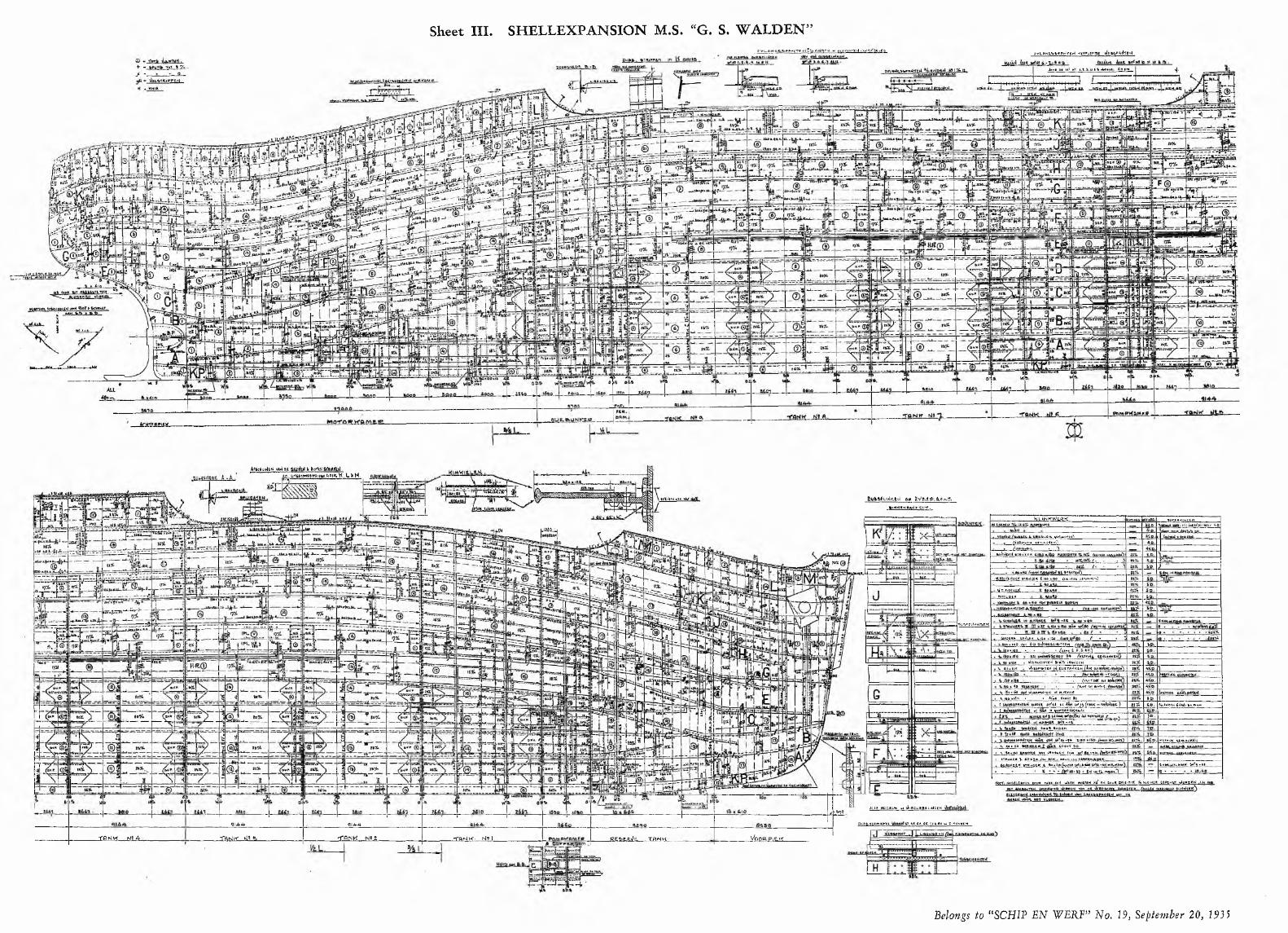
+ - -Tot 9 %J -
gvuAr-ia* M»A.*-re ri 5i> Eidprri. w mn-fanHtH ,h j -63. zvLANc,s<.»Hi-lTti4 -rtma*Tn vkfcfrpftd'ftd
Joa« M Jf> fj* l . l .V A t t AfMttL fiDiBM. +C m« ™ M . H = J
hUrswW tBK -îicürüiü li.11»'j rWcl Wi HCiy AOnfejQIC. y iftjtlKuA
tgllnunnj çt'Itn-HL'O.ÙX!i!±*la •__
feyJttiptij »TRi.lctK ti
W.p,.pLWfltAKftl.pt.ft
N CPtd; B W7HMT A f fto
«a«?;.
a-aacijarrtrJ W.P'JftMaEH% ISO. 150 . Wt»VHHTm 0UETfl'rîrttd~7lM W
( HA 101*fMft fat Q«itH<.
V tfn.tfa Wtw.rMrtH tu nvftpyvEfty Ho »Igft ■_______ » in i* . t f ff iX *aC trtqt »4 jot* » ! } } (*<t A t#,*. K isxmmKTW-W
fol PEd <***<< »» »'■»«'.
bu»». *ODBM.RW ii tKva-Mtrf
■j, J a i j l i t PHUT 30-V jiBtftfl AM >M»rictd lain t,»thihcM f *0 »fto Jx MK - mu^.w ► aojtHRt-X WfttrtGtK t »»»qa Kinnit t»>!
fe ijÎLît. i&sA6* à frwM ,<0. H!gjj£gj5£SSc*ftrlt* K. L * M.
»*)»«« mea. *M'.
UMiL'j
■ftweitertPEK
f APtwumpt Umd
91 A A 914-A
Voa&ElLK-j f l r iK L -t i L a . • TAN K MS a. • fn H K ' N* 1, iL£feE.&Zg. XBriK,# _CofTe.nojw\
Sufcfrtudg.i.t-i 00 2.VftAgLfrfidE.,»lr<m.NH^llCVtY .
c J533
.TUttelfcrtBttf »Trfwtqfc* t no .no fru.tm t » ^ ’.)
suceg» rp<i-bk vita »iso>0.1(80 <MH 0 O- DylHB&ECHnTftlS £ÿs,x ___38 »(00 - » - /g WC £ . F . G> * H ,
tKW.riH-WMH. »ga •(>...
Horn Hn&ELGft-rtH boo« tWtt.O'K *hM pwrtH 'At t>) poort offu-ciK fo'wiitHtft «pomvt ylawpC-Nj. AiAttft n«8L«mftt
ALLE NHGELt» IH ’Jt-gDuBBtudGtH .
■TPf W MA
Du&b.ttgCUHntt tt,5l.tL,<6.^llnao >N Z:T3r(WC.H

Sheet IV. RU D D ER CONSTRUCTION PLAN


h*LolU o ota ti»^ p t titik* ____QJtif.Oii t*«fc_____
i Ccwofdscr-a^ ~t€*K_____ ftiiif.vn« . Ô;«* Lt£*ik.Tr?Ur f Ptavw __________Tryt
__7Ûn yf-Çbf _ _ _rCwftoh. ttgfrd-_Lw^'Kjtutÿ.aii drftif to*V.WftfkbfncK_____Starting.«:»!* ^gastfb
ftirvta ipr^sar- Tyt b*iQ - 0***;.©*lirtifi ^ ' t ? ,- t0(? r*____iù fcritatwig.cil fdtar _ttrxal ÿ- »1 tvr'ifor • ..Tà*V U»bcie»t"»g.arf X*#\*WI *J"*p ««tnmafcQr_____5p4?p V!?f.! . _
~ u »W îtiÿ »y ^ t ^ P _ ___t< b n . fltf __Orient*» d»«mfe**kMLai tihfiinfM__________qbné*r.oe prewne t»>k jîWtfmWhe_
-ÇÇfcfWiWt**W
------------ nSeel:ion at MaindecK.
Descriptor!tookiw? q ir
5 e c t i o n a t T w e e n d e c K .
_ _ _ __iyp«rr«ltfsj______Prrfciaîer .fitMwt. * ■ Ç»v Dsner •£« « 1*« » *31*? Ojxmta.ftre&Mprc ior jiu m ,l>ikMo Alton« ___Co**i«*i$ar __CMi-q.Mi««r............... ...PklL.pvO. t« 'n*f -'^ _ Fl'*.p. _ ._ ......tinjiicmj jy p rjrA« . IwtrlC P?**-. _ _PP.______FyÈÎ tTi*ptrfi»F»........ .... ...fc*eras_ **ryke_ ty*-»p _ _Dr«l«4tsT ptf O
_Sa*itdry.p»r»D'CbndtAl4t«.{MM^ _ _______Hat» __ ____ _________ _____Sç«tf.l*«y9 «ik.giaho.w ____Sjfcbr.cancta«»»* .......EiaptiTatOT'__________Castar** _ 'few* _ A*«*- bo»'*“?........_..i t t v m t c r M t r { fc«t!V*rtK t jlt « »“)-ftKdhMÜf " ’ ....._. 1.... 71.'7.1 ........ F*trrt»w<________ _ _ ....
Spark, a trVittf fth.gH mammator V*rk *r*ttir vu&z'.'+r
L o n g i t u d i n a l S e c t i o nlooking1 R5.
S e c t i o n a t E . R . f l o o r .
S e c t i o n o v e r r r a m e 1 9 . S e c t i o n o v a r f r a m e 4 4 .
Section above Boiler-flat.
Sheet VII. GENERAL ARRANGEMENT OF ENGINE- AND BOILERROOM

S E C T IO N A T E R A M E 6 .LOOKING F O R W A R D . J
OBBCCEBSg. 3BE3Sg
PEPrr'ffqrt.t' STERh rmt txTjwsuiSKivs pips rc-iXhoici LhT> cr nn. cieatDS E C TIO N_E^£. Q PlHioaartD PEVflJHt* we 2p-gs%»w.ta tire or »-.pi tLaaen.
S E C T IO N G - H .
IN CBftGD
TIP
. t i m CBB60 OfLPlf
d»d(J otitiP T:


SECTION J -K
J iJ L L_ J . J Ls S l.

SECTION AT FF^AME 79 LOOKING- AFT
S E C T I O N V -W

Sheet XII. FORWARD PUMPROOM III

DOOR5HEOE CÆH 5.P SO G S ZlÊ N HflftR fiCHTTR
[A
tcwtpjam a
ÜCÎLl
TiNK lTawKR
;owtaT»NK I7 0 M t* n m r.£CH BTftSK;

D O C K Y A R DP A T E N T
GASDEVOURERT H E
APPARATUS F O R G A S F R E E IN G TANK VESSELS
EFFICIENT IN WORKING AND F O O L P R O O F
245 ALREADY DELIVERED
ASK PARTICULARS
ROTTERDAM DRYDOCK C2R O T T E R D A M • P O S T B O X 9 1 3
High-Power Reduction Sear Units for ship propelling machinery (on the test bed) N=3 x 12,500 H. P. n=2455/310
K R U P P
We are supplying: —
Reducing and Speeding-up Cearstip to the highest powers and maximum speeds of rotation, for any application. Greatest stress is laid upon optimum profile and utmost accuracy of teeth. Gear wheels and pinions are made from our time-tested high-grade special steels and cut on precision gear generators. Thus maximum reliability in service, long life, faultless operation, smooth running, and highest efficiency are warranted.
Likewise well proved by experience are our Case-Hardened Gear
Wheels and Pinions whose glass-hard surface, in connection with a tough core, gives them a duration of life 8 to 12 times that of unhardened wheels.
Furthermore included in our respective line of production are:— Rolling Mill Pinions, supplied up to the largest dimensions and
made either from plain carbon steel or bigbest-grade special steel, according to the application envisaged.
Agents for the Netherlands:
Mercem & La Porte N.V., Hmsterdam
KR U PP

R U H R S T A H L A K T I E N G E S E L L S C H A F T
S T A H L W E R K K R I E G E RDüsseldorf-Oberkassel
A g e n t f o r H o l la n d ;
W . J. KRAMER - HAARLEM1 5 9 , V E R S P R O N C K W E G
CAST STEELSTERN FRAMEin 4 pieces supplied for
m.s. “ G. S. W ALDEN”
within 9 weeksinclusive patternmaking
T O T A L W E I G H T 32 T.
m mS h ip 's
Equipmentwhich guarantee quick and economical working
Representatives in H o lland:fo r c r a n e s and t r an s p o r t in g e q u ip m e n t s :
N .V . T E C H N IS C H B U R E A U V A N G. L . D A H LM A N N Rotterdam - 30 Parklaan
fo r rap id ho is t ing a p p l i a n c e s , c o m p re s so r s and com p r e s s e d a i r T oo ls :H E R M A N N S C H A E F E RThe Hague - 34 Wassenaarscheweg - Telephone 114779
fo r t r a n s m is s io n g e a r s : l r . A . C . KO PPEJANThe Hague - 69 Van Boetzelaerlaan - Telephone 563290
Representatives in D u tc h In d ie s :( f o r all p r o d u c t s )
N .V . T E C H N IS C H B U R E A U v.h. K A U M A N N S 8t Co. The Hague, 44 Javastraat - Bandoeng, 75 Bragaweg
P l e a s e w r i t e fo r o u r i l lu s t r a t e d p r o s p e c tu s e s on DECK LEVEL-LUFFING CRANES, SHIPS’ WINCHES a n d REVERSING GEARS for m oto r sh ip s of a l l t y p e s , a s w e l l a s fo r o u r s t a t io n a r y an d p o r t a b l e COM PRESSORS and PNEUMATIC TOOLS for w h a r v e s -W V W - W e sh a l l b e p l e a s e d to a r r a n g e a v is i t f rom o u r r e p r e s e n t a t i v e

n .v . SCHEEPSWERF GEBR. VAN OER WERFDEEST (NIJMEGEN) . TELEPHONE 1
TANKERS, COASTERS ETC.SHIPBUILDERS and REPAIRERS for all kinds of vessels
FIRST CLASS EXECUTIONS MODERATE PRICES FAVOURABLY SITUATED - MODERN ARRANGEMENT
TURBULO TURBULOSPARKCATCHER FINEFILTERcomb, with SILENCER
Installed onm.s.“G. S. W A L D E N ”; supplied by D E U TSCH E W E R F T , Hamburg
See description in this number
Outfit of complete welded
VENTILATORCOWLS & TUBESfor
m.s. “G. S. W A L D E N ”are supplied by
ED. BRAN D T & Co. Ltd. - Eeckeren
R e p r e s e n t a t i v e s for Hol land, Dutch Colonies and B e l g i u m :
N.V. TECHNISCH BUREAU v.h. F. W. UITTENBOGAART & P. DE BEER4 6 6 , M A T H E N E S S E R L A A N - R O T T E R D A M W E S T - T E L E P H O N E 3 0 7 6 2
CARGO-PUMPS
O I L- PUMPS
SCREW PUMPS
HOUTTUIN PUMPSH O U T T U I N ’S M A C H I N E F A B R I E K
U T R E C H T — H OLLANDCOOLI NGWATER-PUMPS
SANITARY PUMPS
B I LGE-PUMPS
HOLLANDLTD.
SHIPBREAKERSHENDRIK IDO AMBACHT
NEAR ROTTERDAM
VAN LESSEN & PUNT25a-b, SC H E E P ST IM M E R M AN SLAA N
R O TTE R D A MSHIPS’ BELLS t e l e p h o n e S 1295
SHIPS’ LANTERNS COMPASSES AND OTHER NAUTICAL INSTRUMENTS
Repairs executed promptly at lowest prices

C. van der Giessen’s WerktuigenfabriekKRIMPEN A/D IJSSEL, TELEPHONE ROTTERDAM 13510
Electric Steering gear ferry-boat Moerdijk
ELECTRIC STEERING GEARS
WORKING DIRECTLY AND WITH CHAIN- TRANSMI SSI ON ON QUADRANT
H I T NEDERLANDSCH OCTROOIT E N N A M E V A N : No. 20881
ARTHUR MAUTERER, T E D O R T M U N D ,
Betreffende een:„ H a lf g o lfv o rm ig of U -v o rm ig ijzeren dam wanddeel, met eener* zijds een messing met half ronde lijst en anderzijds een g r o e f ”wordt te r overneming of te r licentieverleen ing aangeboden.
R E F L E C T A N T E N G E L I E V E N Z IC H T E W E N D E N T O T :
N.V. OCTROOI BUREAU VRIESENDORP & GAADE NI EUWE U IT L E G 3, 'S-GRAVENHAGE
J Ü
(PWËD
F O R G I N G SO R S H I P - B U I L D I N G
S H A F T IN G S , R U D D E R -H E A D S , C R A N K -S H A F T S , T U R B IN E -M A T E R IA L , ETC.
PRESS- UND WALZWERK A.G. - DÜSSELDORF-REISHOLZAGENTS FOR HOLLAND AND COLONIES :
TECH N ISCH BU REA U BURGHOUT & Co. - THE HAGUE - 69, V an B oetze laerlaan - T e l. 553290
H.V. MACHINEFABRIEKVOORHEEN
H. J. KOOPMANDORDRECHT S H IP B U IL D E R S
ENGINEERS • BOILERMAKERS
REPAIRERS
Licensee for Jet-Tube-propulsion patent Kort
GOODRICHcutless
BEARINGSThe ru b b e r - l in e d b e a r in g s
f o r a i l k in d s o f sh ip s , p u m p s , e tc. f o r a l l s h a f t d ia m e te rs .
Apply for informations to the sole-representative for Holland
Technisch Handelsbureau L. R. DOORMAN137, RIOUWSTRAAT THE HAGUE TELEPHONE 554443

(fawn) MANGAAN5TAAL
TO REDUCE H E A V Y TE AR AND W E A R
M A N G A N E S E S T E E LF R O M
BARKERRIDDERKERK
(HOLLAND)
STEELCASTINGS D EP AR T M E N T
N O B I N D I N G B O T H E R - N O C L IP S N O C L A M P S
„Herkules”HOSE SAVERS AND HOSE C O U P L IN G SF O R E V E R Y T R A D E !
Savers ■//— 2" inw. diameter Couplings '/Z— 1” inw. diameter
GIETERIJ, TECHNISCH BUREAU A. VAN AARSTW E E R T (L.) — T E L E P H O N E 12 — P O S T B O X 1
ELECTRO HYDRAULIC STEERING GEARS
“B R O W N -W IL L IA M S -JA N N E Y ”
Telemotors - Steam steer ing gears “W ilson -P irr ie” R eversing engines - H ydraulic S h ip s ’ C ranes - Hoists
Winches - Capstans - W ind lasses etc.
BROW N BROS & CO. Ltd.R O SEBAN K IRON W O R KS - ED IN B U R GH
AGENTS: N.V. TECHNISCH BUREAU STEPHEN ADAM PO ST B O X 362 - T H E H A G U E
Q u a l i t i e s t h a t i n d u c e o w n e r s a n d b u i l d e r s t o e q u i p t h e i r t a n k e r s t h r o u g h o u t w i t h
AdM-AuxiJUaeUss u c h a s : A t l a s S t e e r i n g G e a r , W i n c h e s a n d W i n d l a s s e s , A t l a s O i l - C a r g o , F u e l a n d T r a n s f e r P u m p s , B o i l e r F e e d P u m p s , C o o l i n g a n d D r i n k i n g W a t e r P u m p s , P r e h e a t e r s , E v a p o r a t o r s , A t l a s E c h o - S o u n d e r s , R o l a n d e n c l o s e d , h i g h s p e e d S t e a m - E n g i n e s , A t l a s R e f r i g e r a t i n g P l a n t s , A t l a s - B r o n c e P r o p e l l e r s
A T L A S - W E R K E 1 B R E M E N
FOUR CYCLE DIESEL ENGINE, V. M.(THE WORLDFAMED)
N O W IN A M O D E R N B L O C K C O N S T R U C T IO N F R O M 100 T O 1000 H .P .
A N D F U R T H E R T H E N E W F A S T R U N N E R TYPE A. M.
F o u r cycle D ie se l E n g in e w i th 2 to 8 cyl inders , from 30 to 270 H .P .
N . V . M O T O R E N F A B R I E X D E U T ZN O O R D Z E E -B U ILD IN G
2, K O R T E W I J N B R U G S T R A A T , T E L E P H O N E 24430,R O T T E R D A M
TODD OIL BURNERSPUT ECO NO M Y INTO PR ACTICE IN THE
ifG. S. WALDEN 99
THE OIL BURNERS FITTED TO THE TWO LARGE SCOTCH BOILERS ARE OPERATED BY THE TODD SYSTEM OF AUTOMATIC CONTROL, WHICH ALLOWS FO R T H E BOILERROOM BEING UNATTENDED W H ILE T H E
VESSEL IS AT SEA
COMPLETE O IL FIRED TODD COOKIN G
RAN G E S A R E A L SO FITTED
TODD OIL BURNERS LIMITED130/132 L E A D E N H A L L STRE ET - LONDON E.C. 3
R efiresen ta ted in H o lla n d a n d Colonies by
P. DE BEER100, Schoonebergerweg ROTTERDAM (Holland) Tel. 34149
ZULKE S&BMANOMETERS
KERGER & Go.M arine E lec tr ic a l E ngineers an d W h o le sa le rs19 a - b, W E STZE ED IJK — TELEPHONE 22630 (2 LINES)
ROTTERDAM
S p e c ia l it y
OF ALL ELECTRICAL ACCESSORIES FOR SHIPS AND WHARVES
>>L E V E R D E N W IJ VOOR HET
M.s. „G.S. WALDEN
Solide & Betrouwbaar
N .v . S c h a f f e r & B u d e n b e r gDEN H AAG
SPECIALISTS IN SPRINGSFOR SH IPS
R A IL W A Y S A N D MOTOR T R A N SPO R T
CONTRACTORS TO THE BRITISH ADMIRALTY AND WAR OFFICE
THE WEST BROMWICH SPRING Co. Ltd.G E O R G E S T R E E T - W E S T B R O M W I C H
AGENTS: N .V . TECHNISCH BUREAU STEPHEN ADAMP O S T B O X 3 6 2 - T H E H A G U E
WILLEM SMIT & CO’S TRANSFORMATORENFABRIEK N.V. - NIJMEGEN
T O E S T E L L E N en E L E C T R O D E NVOOR HET
VLAMBOOGLASSCHEN
E ENHEIDS- KWAL ITEIT ELECTRODE
RESISTENS
HUIDFLENSMETHODE
SMIT RESISTENS SMIT RESISTENS
SMIT
SMIT
- * , SMITSMIT
SMIT
SMIT RESISTENS SMIT RESISTENS
Meerdere in l i c h t in g e n worden gaarne ve rs t rek t door
FR. VAN DIJK, SCHIEDAMSCHEWEG 252B, ROTTERDAM W
WATSON-WARNERSTEAM- AND ELECTRICALLY DRIVEN
P U M P SFOR EACH PURPO SE
S O L E - R E P R E S E N T A T I O N F O R H O L L A N D
SPLIETHOFF, BEEUW KES & CO. Ltd.ROTTERDAM, W Z 159, L E U V E H A V E N

F A B R IE K VAN COMPOSITIEVERVENENAMELS, V A R N ISH E S DELFT (Holland)S H I P S ’ B O T T O M A N D ANTI-RUST PAINTS FORSHIPS, BRIDGES AND ALL OTHER IRON CONSTRUCTIONSDelivered red lead composition, white-, red- and mast-colour enamel for the in,s. “ 0 . S. Walden”
RIVETS BOLTS NUTS
N.v. FABRIEK VAN KLINKNAGELS en SCHROEFBOUTENVOORHEEN JOH. SM IT
S L IK K E R V E E RL e t t e r s a n d T e l e g r a m s :
"NAGELFABRIEK”TELEPHONE:
ROTTERDAM 50288
N.V. M O TO R EN FA B R IEK „DE M A A S ”v.h. VENNIX & BERTOU
ROTTERDAMW A A LD IJK 2 7 - T E L . 34116
faSMkUj)L — - - - - 4 i
OMKEERKOPPELINGENM ET INGEBOUWDE V E R T R A G IN G 6— 225 P.K.
„Tu bus” Handel-Maatschappij n .v .Veersche Dijk C271a PIJ PEN H A N D E L
H E N D R IK - ID O -A M B A C H T Telefoon Dordrecht 6475
Groote sorteering
Naadlooze Stalen Pijpenin diameters van 30 to t 650 mm
Levering u i t voorraad - Lage prijzen
Leverancier aan Rijks-,
Prov. en Gem. bedrijven
M E T A A L B E S C H E R M I N G „ P A N T A R O L ”
Éénmaal bestrijken met „P antaro l” houdt apparaten, machines enz. jarenlang g lim mend blank. Bestelt U nog vandaag een proefbus van 1 liter ad f 5 .9 5 , die w ij U franco toezanden met gebruiksaanwijzing
HANDELSBUREAU GAADE v.h . AAMIJL a n g e V ijv e rb e rg 13 - D E N H A A G - T e l. 116 542
CUPOLINE S. K.34
S il ic a r a m m in g m a te r ia l f o r r o t a r y fu rn a c e s , cupo las , la d d ie s , etc.
2a, LAAN VAN ME E RDE RVOORT T H E H A G U E
N.V.W. A. Hoek ’s Machine- en ZuurstoffabriekH E A D O F F I C E :
Air C om pressors fo r Motor Ships 19, havenstraatA pparatus for Oxy-Acetylene Metal-Working SCHIEDAM Oxygen-Nitrogen up to 99 99 % ( H O L L A N D )
Phone 69001-65062
SIMPLUS BRANDBLUSSCHERSG o e d g e k e u r d d o o r d e S c h e e p v a a r t i n s p e c t i e , d e K o n . N e d e r l a n d s c h e B r a n d w e e r v e r e e n i g i n g , en z .O .a , in g e b r u i k bij d e K on . N e d e r l a n d s c h e M a r in e R i jk s w a te r s t a a t ( v e e r p o n te n ) , Zee- e n B i n n e n v a a r t
SIMPLUS B randb luschappara ten N.V., D ordrech t
N.V. Delftsche Machinefabriek & Reparatie-InrichtingDelivery of all kinds of forge-work for Shipbuilding DELFT (Holland)
51, HAAGWEG - TEL. 328SPECIAL PRICES FOR LARGE QUANTITIES
Electric Light and Power Installation M. S. “G. S. Walden”executed by
MIJNSSEN & Co. n.v. - AMSTERDAM
WALKER’SP A C K I N G Used on m.s. G. S. W A L D E N
SUPPLIERS TO PRIN C IPA L SH IPPIN G COM PANIES
D epo ts th ro u g h o u t the w o rld
JA M E S W A L K E R & Co. Ltd.
1 0 2 b, B O O M P J E S R O T T E R D A M
HEAD OFFICE AN D WORKS “LION" W ORKS, Woking, Eng.
ALL T H E CHAIRS ON BOARD O F TH E
M.S. “ G. S. WALDEN”ARE MANUFACTURED BY
N.V. PEIFFERShip s ’ cha i r s Easy ch a i r s an d Sofa s a sp e c ia l i t y CHAIR MANUFACTURERS & UPHOLSTERERS
17 a b e, CATHARINASTRAAT R O TTE R D A M - TE L . 54511
First class references and testimonials on application
KEY5EP Z MACKAYAMSTERDAM-ROTTERDAM-GRONINGEN
B O L N E SDIESEL ENGINES
O. K. ELECTRODES(MADE IN H O LLAN D )
AND
Crosshead type
Doublescavengingair supply
Revolving airvalve
Reduction gear
TELEPHONE
92965 - 9 1 846
W ELDING MACHINESPRACTICALLY T H E BESTF O R A R C W E L D I N G
N.V. NEKEFN.V. Machinefabriek “Bolnes’
v /h j . h . v a n c a p p e l l e n
BOLNES near ROTTERDAM(N E D E R L A N D SC H E K JE L L B E R G E L E C T R O D E N FABR IE K)
45-47, KARPERWEG, AMSTERDAM-ZUID T e l . R o t t e r d a m
10398 - 14398T e l e g r a m s
V a n C a p p e l l e n B o l n e s
Shipowners and Shippers!
D o you L o w •I.*. ^
S e a p o rt o f D o rJre c lit .The port of Dordrecht has the most modern equipment for quick and accurate dispatch of bulk cargoes. The port of Dordrecht has factory sites, sheds, warehouse accommodation and quays to let with railway connections on deep water (28 feet).
For full particulars apply to the Town Clerk or M unicipal Harbour-M aster, Dordrecht, H olland
FIRE ON BOARDQUICKLY EXTINGUISHED
provided that the ship is equipped with
MINIMAXfire extinguishers.
Therefore most of the largest and modernest liners are supplied with
MINIMAXAll sorts of foam- and carbondioxide (CO 2) plants for ships according to the modernest
devices are designed and installed by
N.V. IFFA-MINIMAX AMSTERDAM C, 197, KEIZERSGRACHT