FY2009–2034 Unmanned Systems Integrated Roadmap UVS/Publicatii-internationale... · FY2009–2034...
210
FY2009–2034 Unmanned Systems Integrated Roadmap Page i
Transcript of FY2009–2034 Unmanned Systems Integrated Roadmap UVS/Publicatii-internationale... · FY2009–2034...
FY2009–2034 Unmanned Systems Integrated Roadmap
Page i

FY2009–2034 Unmanned Systems Integrated Roadmap
Page ii
This page is intentionally left blank.
FY2009–2034 Unmanned Systems Integrated Roadmap
Page iii
FY2009–2034 Unmanned Systems Integrated Roadmap
Page iv
FY2009–2034 Unmanned Systems Integrated Roadmap
Page v
Contents Executive Summary................................................................................................................................. xiii Chapter 1. Introduction............................................................................................................................... 1
Purpose ....................................................................................................................................................1 Scope .......................................................................................................................................................1 Background ..............................................................................................................................................2
Current State of Unmanned Systems .................................................................................................2 Congressional Direction ......................................................................................................................4
Chapter 2. Vision for the Future Development and Employment of Unmanned Systems within the Department of Defense............................................................................................................. 7
Unmanned Systems Applied to Joint Capability Areas (JCAs)................................................................7 Battle Space Awareness ..........................................................................................................................8 Force Application....................................................................................................................................10 Protection ...............................................................................................................................................11 Logistics .................................................................................................................................................12 Building Partnerships .............................................................................................................................13 Force Support.........................................................................................................................................13 Command and Control (C2) ...................................................................................................................14 Net Centric .............................................................................................................................................14 Unmanned Systems Performance Envelope .........................................................................................27 Performance Across Domains ...............................................................................................................27 A Discussion of Reliability, Availability, and Maintainability for Unmanned Systems ............................28 Performance Specific to Domains..........................................................................................................29 Air Domain Specific Performance Attributes..........................................................................................30 Ground Domain Specific Performance Attributes ..................................................................................31 Maritime Domain Specific Performance Attributes ................................................................................31 Goals and Objectives .............................................................................................................................33
Chapter 3. Unmanned Systems Path Forward....................................................................................... 37 Methodology for Analysis .......................................................................................................................37 Strengths and Opportunities ..................................................................................................................37 Air Domain..............................................................................................................................................37 Ground Domain ......................................................................................................................................37 Maritime Domain ....................................................................................................................................38 Challenges and Risks ............................................................................................................................39 Recommended Actions ..........................................................................................................................43
Chapter 4. Advancing Unmanned Systems Technologies ................................................................... 47 Unmanned Systems Technology Enablers............................................................................................47 Aligning Common Technologies ............................................................................................................47 Key/Pacing Technologies.......................................................................................................................48 Air Domain..............................................................................................................................................48 Ground Domain ......................................................................................................................................49 Maritime Domain ....................................................................................................................................49
Appendix A. Unmanned Aircraft Systems (UAS)................................................................................... 51
FY2009–2034 Unmanned Systems Integrated Roadmap
Page vi
A.1 Unmanned Aircraft Systems.........................................................................................................51 A.1.1 A160 Hummingbird...............................................................................................................51 A.1.2 Aerosonde ............................................................................................................................52 A.1.3 Aqua/Terra Puma.................................................................................................................53 A.1.4 Battlefield Air Targeting Micro Air Vehicle (BATMAV) – WASP III.......................................54 A.1.5 Broad Area Maritime Surveillance Unmanned Aircraft System (BAMS UAS) .....................55 A.1.6 Buster ...................................................................................................................................56 A.1.7 XM-156 Class I.....................................................................................................................57 A.1.8 Combat Medic Unmanned Aircraft System (UAS) for Resupply and Evacuation................58 A.1.9 FINDER ................................................................................................................................59 A.1.10 Global Observer ...................................................................................................................60 A.1.11 Improved Gnat Extended Range (I-Gnat-ER) “Warrior Alpha” / Extended Range/Multi-
purpose (ER/MP) Block 0.....................................................................................................61 A.1.12 Maverick ...............................................................................................................................62 A.1.13 MQ-1 Predator......................................................................................................................63 A.1.14 MQ-1C Extended Range/Multi-purpose (ER/MP) ................................................................64 A.1.15 MQ-5B Hunter ......................................................................................................................65 A.1.16 MQ-8 Fire Scout ...................................................................................................................66 A.1.17 MQ-9 Reaper (formerly Predator B).....................................................................................67 A.1.18 Onyx Autonomously Guided Parafoil System ......................................................................68 A.1.19 RQ-11 Pathfinder Raven......................................................................................................69 A.1.20 RQ-14 Dragon Eye/Swift ......................................................................................................70 A.1.21 RQ-15 Neptune ....................................................................................................................71 A.1.22 Gasoline Micro Air Vehicle (gMAV)......................................................................................72 A.1.23 RQ-4 Global Hawk ...............................................................................................................73 A.1.24 RQ-4 Global Hawk Maritime Demonstration (GHMD) .........................................................74 A.1.25 RQ-7 Shadow 200................................................................................................................75 A.1.26 ScanEagle ............................................................................................................................76 A.1.27 Silver Fox .............................................................................................................................77 A.1.28 Small Tactical UAS (STUAS)/Tier II UAS ............................................................................78 A.1.29 Tactical Mini-Unmanned Air Vehicle (TACMAV)..................................................................79 A.1.30 Unmanned Combat Aircraft System – Carrier Demonstration (UCAS-D)............................80 A.1.31 Wasp ....................................................................................................................................81 A.1.32 XM 157 Class IV UAS ..........................................................................................................82 A.1.33 XPV-1 Tern...........................................................................................................................83 A.1.34 XPV-2 Mako .........................................................................................................................84
A.2 Unmanned Airship Systems .........................................................................................................85 A.2.1 Advanced Airship Flying Laboratory (AAFL)........................................................................85 A.2.2 Hybrid Unmanned Aircraft Vehicle (HUAV) Persistent Elevated Reconnaissance
Surveillance Intelligence Unmanned System (PERSIUS) ...................................................86 A.2.3 Joint Land Attack Elevated Netted Sensor (JLENS)............................................................87 A.2.4 Rapid Aerostat Initial Deployment (RAID)............................................................................88 A.2.5 Rapidly Elevated Aerostat Platform (REAP) ........................................................................89 A.2.6 Tethered Aerostat Radar System (TARS)............................................................................90
A.3 Unmanned Aircraft System (UAS) Airspace Integration ..............................................................91
FY2009–2034 Unmanned Systems Integrated Roadmap
Page vii
A.3.1 Overview ..............................................................................................................................91 A.3.2 Background ..........................................................................................................................91 A.3.3 Command, Control, Communications ................................................................................101 A.3.4 Future Environment............................................................................................................102 A.3.5 Department of Defense (DoD) Organizations with Roles in Unmanned Aircraft System
(UAS) Airspace Integration.................................................................................................103 Appendix B. Unmanned Ground Vehicles (UGVs) .............................................................................. 111
B.1 All-Purpose Remote Transport System (ARTS).........................................................................111 B.2 Anti-Personnel Mine Clearing System, Remote Control (MV-4B)..............................................112 B.3 Armed Robotic Vehicle (ARV) ....................................................................................................113 B.4 Assault Breacher Vehicle (ABV).................................................................................................114 B.5 Battlefield Extraction-Assist Robot (BEAR)................................................................................115 B.6 Chemical, Biological, Radiological, Nuclear (CBRN) UGV (CUGV) ..........................................117 B.7 Crusher Unmanned Ground Combat Vehicle ............................................................................118 B.8 Dragon Runner ...........................................................................................................................119 B.9 Gladiator Tactical Unmanned Ground Vehicle (TUGV) .............................................................120 B.10 Man Transportable Robotic System (MTRS) MK 1 MOD 0 Robot, Explosive Ordnance Disposal
(EOD) and MK 2 MOD 0 Robot, Explosive Ordnance Disposal (EOD) .....................................121 B.11 Mine Area Clearance Equipment (MACE)..................................................................................122 B.12 MK 3 MOD 0 Remote Ordnance Neutralization System (RONS) ..............................................123 B.13 MK 4 MOD 0 Robot, Explosive Ordnance Disposal (EOD)........................................................124 B.14 Mobile Detection, Assessment, and Response System (MDARS) ............................................125 B.15 Multifunction, Agile, Remote-Controlled Robot (MARCbot) .......................................................126 B.16 Multifunction Utility/Logistics Equipment Vehicle (MULE)..........................................................127 B.17 Omni-Directional Inspection System (ODIS)..............................................................................128 B.18 Robo-Trencher ...........................................................................................................................129 B.19 Robotic Combat Casualty Extraction and Evacuation................................................................130 B.20 Small Unmanned Ground Vehicle (SUGV) ................................................................................131 B.21 Throwbot.....................................................................................................................................132 B.22 Toughbot ....................................................................................................................................133
Appendix C. Unmanned Maritime Systems (UMSs) ............................................................................ 135 C.1 Unmanned Surface Vehicles (USVs) .........................................................................................135
C.1.1 Fleet Class USVs ...............................................................................................................135 C.2 Unmanned Undersea Vehicles (UUVs)......................................................................................138
C.2.1 Heavyweight UUVs ............................................................................................................138 C.2.2 Lightweight Vehicles (LWVs) .............................................................................................141 C.2.3 Man-Portable UUVs ...........................................................................................................143
Appendix D. Technology Enabler Data Sheets.................................................................................... 150 D.1 3D World Modeling.....................................................................................................................150 D.2 Active Signature Management ...................................................................................................150 D.3 Architecture Proprietary..............................................................................................................150 D.4 Artificial Muscle Systems............................................................................................................150 D.5 Automatically Deployed Communication Relays........................................................................151 D.6 Autonomous Robotic Capability Suite (ARCS) ..........................................................................151 D.7 Battery Powered - Long Endurance Power Source for Small UGVs .........................................152
FY2009–2034 Unmanned Systems Integrated Roadmap
Page viii
D.8 Battlefield Extraction – Assist Robot (BEAR) .............................................................................152 D.9 Bio-mass Reactor Power............................................................................................................154 D.10 Biomimetic Human Detection .....................................................................................................154 D.11 BioRobotics ................................................................................................................................154 D.12 Bird Dog/Warfighter’s Associate.................................................................................................154 D.13 CENTAUR Ground Mobility System...........................................................................................155 D.14 Chemical Robots (ChemBots)....................................................................................................155 D.15 Collaborative Networked Autonomous Vehicles (CNAV)...........................................................156 D.16 Communications/Navigation Network Node (CN3) ....................................................................156 D.17 Complex Terrain Mobility............................................................................................................156 D.18 Constrained Radio Frequency (RF) ...........................................................................................156 D.19 Cooperative Multi-Vehicle Road Network Search ......................................................................157 D.20 Covert & Self-concealing Behaviors...........................................................................................157 D.21 Electromechanical/Hydraulic ......................................................................................................157 D.22 Extreme Weather Capable (Sensors, Electro-mechanical)........................................................158 D.23 Front End Robotics Enabling Near-Term Demonstration (FREND)...........................................158 D.24 Heterogeneous Airborne Reconnaissance Team (HART).........................................................158 D.25 Hierarchical Collaborative Behaviors .........................................................................................159 D.26 High Speed Intelligent Networked Communications ..................................................................159 D.27 Highly Representative World Model ...........................................................................................159 D.28 Human Detection on the Move...................................................................................................159 D.29 Human-Like Dexterity .................................................................................................................160 D.30 Hybrid Bio-mechanical Systems.................................................................................................160 D.31 Intelligent Frequency Selecting Radio Frequency (RF) .............................................................160 D.32 Intelligent Mobile Grenade .........................................................................................................161 D.33 Joint Convoy Active Safety System (JCASS) ............................................................................161 D.34 Joint Tactical Radio System (JTRS) Networked Communications ............................................161 D.35 Ku MiniTCDL for STUAS/Tier II..................................................................................................162 D.36 Local Visualization......................................................................................................................162 D.37 Manipulator Dexterity..................................................................................................................162 D.38 Man-Portable ISR Robot ............................................................................................................163 D.39 Micro Air Vehicle (MAV) .............................................................................................................163 D.40 Modeling and Simulation ............................................................................................................164 D.41 Multi Dimensional Mobility Robot (MDMR) ................................................................................164 D.42 Multi-mission Modular Unmanned Aircraft System (UAS) Chemical, Biological, Radiological, and
Nuclear (CBRN) Payloads Initiative ...........................................................................................164 D.43 Multi-modal Human Detection ....................................................................................................165 D.44 Nano-Flapping Air Vehicle..........................................................................................................165 D.45 Navigation...................................................................................................................................165 D.46 Next Generation Power Resources............................................................................................167 D.47 Nightingale II – Integrated UAS/UGV System............................................................................167 D.48 Non-Radio Frequency (RF) Communications ............................................................................168 D.49 Opportunistic Communications ..................................................................................................168 D.50 Opportunistic Power Grazing .....................................................................................................168 D.51 Organic Air Vehicle – II (OAV-II) ................................................................................................169
FY2009–2034 Unmanned Systems Integrated Roadmap
Page ix
D.52 Passive Signature Management ................................................................................................169 D.53 Rapid Eye ...................................................................................................................................169 D.54 Real-time High Fidelity World Modeling .....................................................................................169 D.55 Robotic Extraction, Evacuation and Enroute Combat Casualty Care (RE3C3).........................170 D.56 Robotic Force Health Protection Payloads for Unmanned Ground Vehicles.............................170 D.57 Safety Response (Anti-tampering) .............................................................................................171 D.58 Safety Response ........................................................................................................................171 D.59 Safety Response (CBRN) ..........................................................................................................171 D.60 Self-Forming Unmanned Aircraft System (UAS) Communications Network..............................172 D.61 Sense and Avoid (S&A)..............................................................................................................172 D.62 Sensors to Enable Robust Harsh-Weather Operations .............................................................172 D.63 Stealthy, Persistent, Perch and Stare (SP2S)............................................................................173 D.64 Super Dexterity...........................................................................................................................173 D.65 Tactical Amphibious Ground Support System (TAGS) ..............................................................173 D.66 Vision of the Trauma Pod...........................................................................................................173 D.67 Voice Control ..............................................................................................................................174 D.68 Vulture ........................................................................................................................................174
Appendix E. Joint Capability Area (JCA) Definitions .......................................................................... 176 Appendix F. Unmanned Systems Standards ....................................................................................... 178
F.1 Interoperability Requirements ....................................................................................................178 F.2 Unmanned Systems Standards..................................................................................................178
F.2.1 Unmanned Air Standards...................................................................................................180 F.2.2 Unmanned Ground Standards ...........................................................................................181 F.2.3 Unmanned Maritime Standards .........................................................................................181
Appendix G. Unmanned Systems Points of Contact .......................................................................... 182 Appendix H: Acronym List ..................................................................................................................... 185

FY2009–2034 Unmanned Systems Integrated Roadmap
Page x
This page is intentionally left blank.
FY2009–2034 Unmanned Systems Integrated Roadmap
Page xi
List of Tables and Figures Table 1. FY2009–15 President’s Budget for Unmanned Systems ...............................................................4 Table 2. Density of Named Systems within Each JCA .................................................................................8 Table 3. Named Unmanned Systems Associated with Battle Space Awareness ........................................9 Table 4. Named Unmanned Systems Associated with Force Application..................................................10 Table 5. Named Unmanned Systems Associated with Protection..............................................................12 Table 6. Named Unmanned Systems Associated with Logistics................................................................13 Table 7. Named Unmanned Systems Associated with Building Partnerships............................................13 Table 8. Named Unmanned Systems Associated with Force Support .......................................................14 Table 9. Named Unmanned Systems Associated with Command and Control .........................................14 Table 10. Named Unmanned Systems Associated with Net-Centric..........................................................15 Figure 1. Air Domain JCA Mapping ............................................................................................................17 Figure 1. Air Domain JCA Mapping Continued...........................................................................................18 Figure 1. Air Domain JCA Mapping Continued...........................................................................................19 Figure 2. Ground Domain JCA Mapping.....................................................................................................21 Figure 2. Ground Domain JCA Mapping Continued ...................................................................................22 Figure 2. Ground Domain JCA Mapping Continued ...................................................................................23 Figure 3. Maritime Domain JCA Mapping ...................................................................................................25 Figure 3. Maritime Domain JCA Mapping Continued .................................................................................26 Figure 4. Performance Envelope Common to All Domains ........................................................................27 Figure 5. Air Domain Performance Envelope .............................................................................................31 Figure 6. Ground Domain Performance Envelope......................................................................................31 Figure 7. Maritime Domain Performance Envelope....................................................................................33 Table 11. Goals and Objectives..................................................................................................................36 Table 12. Recommended Actions...............................................................................................................45 Figure 8. Technology Enablers Common to All Domains ...........................................................................48 Figure 9. Air Domain Technology Enablers ................................................................................................49 Figure 10. Ground Domain Technology Enablers ......................................................................................49 Figure A.1. Joint FAA/OSD Approach to Regulating UAS..........................................................................92 Figure A.2. U.S. Military Aircraft and UAS Class A Mishap Rates (Lifetime), 1986–2006 .........................93 Figure A.3. UAS and Airspace Classes of the NAS ...................................................................................95 Table A.1. Alignment of UAS Categories with FAA Regulations ................................................................95 Figure A.4. JUAS CONOPS UAS Categories.............................................................................................97 Figure A.5. JIPT Functional Organization .................................................................................................104 Figure A.6. Track 1 and Track 2 Strategies ..............................................................................................106 Figure A.7. Track 1, Track 2, and SC-203 ................................................................................................107 Table F.1. Organizations Developing Standards for Unmanned Systems ...............................................180

FY2009–2034 Unmanned Systems Integrated Roadmap
Page xii
This page is intentionally left blank.
FY2009–2034 Unmanned Systems Integrated Roadmap
Page xiii
EXECUTIVE SUMMARY In today’s military, unmanned systems are highly desired by combatant commanders (COCOMs) for their versatility and persistence. By performing tasks such as surveillance; signals intelligence (SIGINT); precision target designation; mine detection; and chemical, biological, radiological, nuclear (CBRN) reconnaissance, unmanned systems have made key contributions to the Global War on Terror (GWOT). As of October 2008, coalition unmanned aircraft systems (UAS) (exclusive of hand-launched systems) have flown almost 500,000 flight hours in support of Operations Enduring Freedom and Iraqi Freedom, unmanned ground vehicles (UGVs) have conducted over 30,000 missions, detecting and/or neutralizing over 15,000 improvised explosive devices (IEDs), and unmanned maritime systems (UMSs) have provided security to ports.
In response to the Warfighter demand, the Department has continued to invest aggressively in developing unmanned systems and technologies. That investment has seen unmanned systems transformed from being primarily remote-operated, single-mission platforms into increasingly autonomous, multi-mission systems. The fielding of increasingly sophisticated reconnaissance, targeting, and weapons delivery technology has not only allowed unmanned systems to participate in shortening the “sensor to shooter” kill chain, but it has also allowed them to complete the chain by delivering precision weapons on target. This edition of the Unmanned Systems Roadmap attempts to translate the benefit of these systems and technologies into the resultant combat capability by mapping specific unmanned systems to their contributions to Joint Capability Areas (JCAs) such as Battlespace Awareness, Force Application, Force Support, and Logistics.
As the Department of Defense (DoD) continues to develop and employ an increasingly sophisticated force of unmanned systems over the next 25 years (2009 to 2034), technologists, acquisition officials, and operational planners require a clear, coordinated plan for the evolution and transition of unmanned systems technology. This document incorporates a vision and strategy for UAS, UGVs, and UMSs (defined as unmanned undersea vehicles (UUVs) and unmanned surface vehicles (USVs)) that is focused on delivery of warfighting capability. Its overarching goal, in accordance with the Defense Planning Guidance (DPG), is to focus military departments and defense agencies toward investments in unmanned systems and technologies that meet the prioritized capability needs of the Warfighter that include:
1. Reconnaissance and Surveillance. This remains the number one COCOM priority for unmanned systems. While the demand for full-motion video (FMV) remains high, there is an increasing demand for wide-area search and multi-INT capability. Processing, Exploitation, and Dissemination (PED) remains a key area highlighting the need for interoperability.
2. Target Identification and Designation. The ability to positively identify and precisely locate military targets in real-time is a current shortfall with DoD UAS. Reducing latency and increasing precision for GPS-guided weapons is required.
3. Counter-Mine and Explosive Ordnance Disposal. Since World War II, sea mines have caused more damage to US warships than all other weapons systems combined. IEDs are the number one cause of coalition casualties in Operation Iraqi Freedom. A significant amount of effort is already being expended to improve the military’s ability to find, mark, and destroy land and sea mines as well as IEDs.
FY2009–2034 Unmanned Systems Integrated Roadmap
Page xiv
4. Chemical, Biological, Radiological, Nuclear (CBRN) Reconnaissance. The ability to find chemical and biological agents, as well as radiological or nuclear weapon materiel and/or hazards, and to survey the extent of affected areas while minimizing the exposure of personnel to these agents is a crucial effort.
The Office of the Secretary of Defense (OSD) is responsible for ensuring unmanned systems support the Department’s larger goals of fielding transformational capabilities, establishing joint standards, and controlling costs. OSD has established the following broad goals to steer the Department in that direction.
Goal 1. Improve the effectiveness of COCOM and partner nations through improved integration and Joint Services collaboration of unmanned systems.
Goal 2. Support research and development activities to increase the level of automation in unmanned systems leading to appropriate levels of autonomy, as determined by the Warfighter for each specific platform.
Goal 3. Expedite the transition of unmanned systems technologies from research and development activities into the hands of the Warfighter.
Goal 4. Achieve greater interoperability among system controls, communications, data products, data links, and payloads/mission equipment packages on unmanned systems, including TPED (Tasking, Processing, Exploitation, and Dissemination).
Goal 5. Foster the development and practice of policies, standards, and procedures that enable safe and effective operations between manned and unmanned systems.
Goal 6. Implement standardized and protected positive control measures for unmanned systems and their associated armament.
Goal 7. Ensure test capabilities support the fielding of unmanned systems that are effective, suitable, and survivable.
Goal 8. Enhance the current logistical support process for unmanned systems.
This Unmanned Systems Integrated Roadmap represents the Department’s first truly synchronized effort that increases the focus on unmanned systems, and through interoperability with manned systems, establishes a vision in support of our Warfighters. This Roadmap projects the types of missions that could be supported in the future by unmanned solutions, and the improvements in performance that can be expected as a result of investment into identified critical unmanned technologies. It recommends actions the Department can pursue to bring the projected vision to fruition. In short, this Roadmap informs decision makers of the potential to more effectively and efficiently support the Warfighter by continuing to leverage unmanned systems.
FY2009–2034 Unmanned Systems Integrated Roadmap
Page 1
CHAPTER 1. INTRODUCTION Purpose The purpose of this United States Department of Defense (DoD) Roadmap is to propose a feasible vision for capitalizing on unmanned systems technologies so that the Warfighter can conduct missions more effectively with less risk. The last six years have proven, without a doubt, that unmanned systems operating in the air, on land, and in maritime domains have significantly contributed to accomplishing the Department’s missions. These successes, however, likely represent only a fraction of what is possible and desirable by employing unmanned systems. This Roadmap, developed by the Department’s subject matter experts (SMEs), establishes recommendations for technologies to pursue, departmental strengths and opportunities to exploit, risks and challenges to overcome, and actions that can be taken to bring to fruition whatever aspects of this proposed future vision best serves the future needs of the Warfighters. This Roadmap is intended to serve a variety of audiences. It has been deliberately constructed to inform the DoD leadership and be responsive to the requirements set forth in Section 141 of the John Warner National Defense Authorization Act for Fiscal Year (FY) 2007 (Public Law 109-364). It lays out the possibilities, issues, and implications associated with the development and employment of unmanned systems. Accordingly, the Roadmap identifies those missions that could, in the future, feasibly be performed by unmanned systems and lays out a prospective associated timeline. Finally, this Roadmap discusses unmanned systems performance characteristics expected to be needed by the industrial base to develop the types of enabling technologies supportive of the Warfighter. Scope This Roadmap lays out a recommended unmanned systems vision across a 25-year period. It encompasses all three environmental domains: air, ground, and maritime. It captures those unmanned systems that are already funded through the 2009 President’s Budget (PB09) and offers speculation as to what types of systems could be feasibly developed and employed outside the Future Years Defense Plan (FYDP) through 2034. It identifies the types of tasks that could be accomplished using unmanned systems within the Joint Capability Areas (JCAs) and highlights the multi-functional nature of such systems as appropriate. The Roadmap describes an expanding performance envelope that captures the current state-of-the-art and projects an evolution in performance across the 25 years. From these projections, the Roadmap identifies technologies that will need to be developed and matured in order to bring about the evolving performance. In essence, the Roadmap lays out a vision in terms of potential missions that could be performed by unmanned systems, the desired functionality and performance needed by the systems to perform those missions, and the technology advancements needed to achieve such performance. From this vision, the Roadmap addresses the associated strengths and opportunities that can be capitalized on to achieve such a vision. It also identifies those risks and challenges that must be mitigated and addressed in order to bring about such a vision. Finally, the Roadmap articulates a series of recommended actions that can position the Department to take advantage of the opportunities and overcome the challenges. What the Roadmap does not do is create operational concepts, identify requirements, or program funds to invest in technology development and system acquisition. This document is a map that
FY2009–2034 Unmanned Systems Integrated Roadmap
Page 2
describes a path the Department can take in progressing from the current use of unmanned systems to the vision that is laid out in the document. It does not supersede the need for the Department to conduct the analysis and decision making associated with identifying the best means to satisfy capability gaps. Nor does it attempt to convey recommendations for optimized mixes of manned and unmanned systems or optimized mixes of Joint and Service unique unmanned systems. These issues and others associated with investments, force structure, and new systems acquisition can only be informed by this Roadmap and must be addressed with deliberation at the appropriate point in the future. There will likely be decisions made in the future that choose manned systems over unmanned systems to accomplish tasks and missions for reasons of operational effectiveness, affordability, technical maturity, etc. These future decisions however, will be more deliberately informed because of the analysis and methodology employed in creating this Roadmap. It must be fully understood that, as time progresses and budgetary pressures come to bear, not all recommendations and aspects of the future projected in this Roadmap can or will be realized. Background Prior to 2007, each of the unmanned systems domains (i.e., air, ground, maritime) published and updated individual roadmaps and/or master plans. It was recognized that opportunities for efficiencies and greater interoperability could be achieved by establishing strategic planning for unmanned systems via an integrated approach, which is evidenced in the publication of the first Integrated Unmanned Systems Roadmap. This first integrated Roadmap identified the various systems in the inventory and captured all of the research, development, test, and evaluation (RDT&E), Procurement, and Operations and Maintenance (O&M) funding programmed for unmanned systems. It laid out goals and objectives for the Department in continuing to pursue development and employment for unmanned systems and touched on technological challenges that would need to be addressed to achieve more effective interoperability. This 2009 Roadmap has deliberately used the 2007 Roadmap as a point of departure for: Conducting a more integrated approach to identifying how unmanned systems can be
optimized to support a greater set of mission areas Identifying those common areas of technology maturation that can lead to performance
improvements in all domains Identifying the technology enablers needed to foster the ability to conduct collaborative
operations between multiple unmanned systems in multiple domains
Current State of Unmanned Systems Air Domain Unmanned aircraft systems (UAS) have experienced explosive growth in recent history and have proved to be an invaluable force multiplier for the Joint Force Commander (JFC). UAS can provide both a persistent and highly capable intelligence, surveillance, and reconnaissance (ISR) platform to troops requiring a look “beyond the next hill” in the field or “around the next block” in congested urban environments and, if necessary, also assist troops in contact or perform strike missions against high value targets (HVTs) of opportunity. UAS also have the ability to be dynamically re-tasked long distances across the battlespace as needed by the JFC and operate beyond line of sight (BLOS). Under a BLOS concept of operations (CONOPS), the forward footprint of the UAS is minimized which allows both the pilots and sensor operators to fly
FY2009–2034 Unmanned Systems Integrated Roadmap
Page 3
missions from the U.S. while maintaining only a small contingent forward in the operational environment. The smaller class UAS have proven their worth at Company and Platoon level, giving short-term line of sight (LOS) ISR capability to individual soldiers and also extending the reach of soldiers providing base perimeter defense. These smaller, less expensive UAS have become an integral and essential tool for ground forces and have proliferated throughout the operational environment. All Services currently employ a number of different systems across the spectrum from large to small UAS. Ground Domain Unmanned ground vehicles (UGVs), while not as prolific or at the investment level of UAS, nonetheless have proven their ability to contribute to combat operations. Since operations in Iraq and Afghanistan began, more than 6,000 UGVs have been procured and deployed to theater. With the success of the UGVs in theater operations, Joint Urgent Operational Need Statements (JUONS) have been submitted for UGVs that can support missions ranging from reconnaissance for infantry and engineering units, to convoy operations, to advanced improvised explosive device (IED) defeat. In some cases, the JUONS have been satisfied via upgrades to existing UGVs and/or procurement of new UGVs. In other cases, the JUONS were asking for capabilities beyond the current technical state of the art. Although such solutions could not be provided to the theater, funding for technology development toward achieving the requested capability was programmed and work initiated to generate UGV systems that can satisfy the requirements. Special Operations Command (SOCOM) is conducting a program that seeks to develop UGVs for employment in reconnaissance, supply, and protection missions for Special Forces units in forward operating situations. United States Northern Command (NORTHCOM) and Pacific Command (PACOM) have both requested technology development support for UGVs that can conduct tunnel reconnaissance and mapping, and supply transport in complex terrain. The Defense Advanced Research Projects Agency (DARPA) completed its Urban Challenge with several teams successfully navigating and driving in urban traffic in fully autonomous mode within the 6-hour time limit. The DARPA Challenges have resulted in sensor breakthroughs that not only push the state of the art for UGVs but are also applicable to unmanned systems in the air and maritime domains. Industry has also taken note of the forward momentum in UGVs. After a request from DoD to form a consortium of robotics companies and academic institutions, over 80 organizations inclusive of defense contractors, non-traditional contractors, and universities, joined a robotics consortium that was formed in 4 months. An Other Transaction Agreement (OTA) was negotiated and signed between DoD and the Robotics Technology Consortium, which enabled industry to participate in the DoD ground robotics technology assessment process. This set a new, unprecedented level of partnership between DoD and industry/academia, resulting in greater awareness by DoD into industry independent research and development and industry insights into the priorities of DoD users for UGVs in support of military missions. These insights will better inform future investments into ground robotics technology development and better focus industry independent efforts to create UGVs suitable for military missions. Maritime Domain Unmanned maritime vehicles (UMVs) present new opportunities to augment our naval forces and maintain maritime superiority around the world. Fleet experimentation and limited real-world application have validated concepts of fleet transformation and force multiplication using
FY2009–2034 Unmanned Systems Integrated Roadmap
Page 4
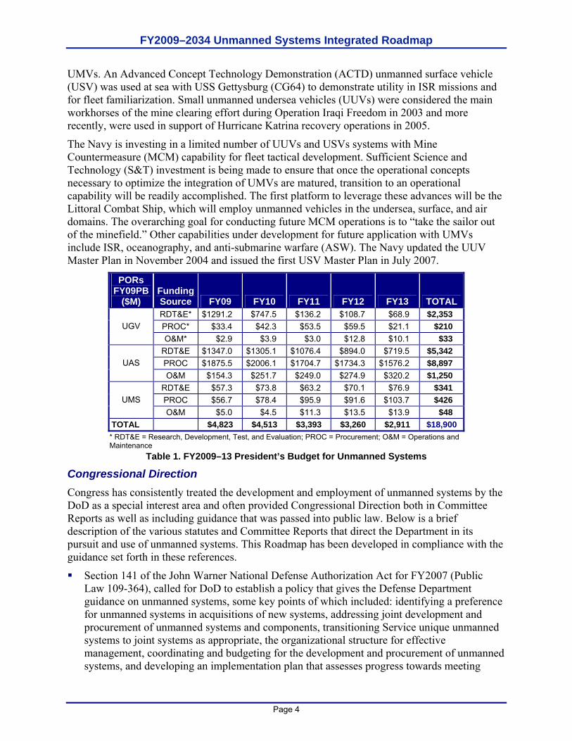
UMVs. An Advanced Concept Technology Demonstration (ACTD) unmanned surface vehicle (USV) was used at sea with USS Gettysburg (CG64) to demonstrate utility in ISR missions and for fleet familiarization. Small unmanned undersea vehicles (UUVs) were considered the main workhorses of the mine clearing effort during Operation Iraqi Freedom in 2003 and more recently, were used in support of Hurricane Katrina recovery operations in 2005.
The Navy is investing in a limited number of UUVs and USVs systems with Mine Countermeasure (MCM) capability for fleet tactical development. Sufficient Science and Technology (S&T) investment is being made to ensure that once the operational concepts necessary to optimize the integration of UMVs are matured, transition to an operational capability will be readily accomplished. The first platform to leverage these advances will be the Littoral Combat Ship, which will employ unmanned vehicles in the undersea, surface, and air domains. The overarching goal for conducting future MCM operations is to “take the sailor out of the minefield.” Other capabilities under development for future application with UMVs include ISR, oceanography, and anti-submarine warfare (ASW). The Navy updated the UUV Master Plan in November 2004 and issued the first USV Master Plan in July 2007.
PORs FY09PB
($M) Funding Source FY09 FY10 FY11 FY12 FY13 TOTAL RDT&E* $1291.2 $747.5 $136.2 $108.7 $68.9 $2,353 PROC* $33.4 $42.3 $53.5 $59.5 $21.1 $210 UGV O&M* $2.9 $3.9 $3.0 $12.8 $10.1 $33
RDT&E $1347.0 $1305.1 $1076.4 $894.0 $719.5 $5,342 PROC $1875.5 $2006.1 $1704.7 $1734.3 $1576.2 $8,897 UAS O&M $154.3 $251.7 $249.0 $274.9 $320.2 $1,250
RDT&E $57.3 $73.8 $63.2 $70.1 $76.9 $341 PROC $56.7 $78.4 $95.9 $91.6 $103.7 $426 UMS O&M $5.0 $4.5 $11.3 $13.5 $13.9 $48
TOTAL $4,823 $4,513 $3,393 $3,260 $2,911 $18,900 * RDT&E = Research, Development, Test, and Evaluation; PROC = Procurement; O&M = Operations and Maintenance
Table 1. FY2009–13 President’s Budget for Unmanned Systems
Congressional Direction Congress has consistently treated the development and employment of unmanned systems by the DoD as a special interest area and often provided Congressional Direction both in Committee Reports as well as including guidance that was passed into public law. Below is a brief description of the various statutes and Committee Reports that direct the Department in its pursuit and use of unmanned systems. This Roadmap has been developed in compliance with the guidance set forth in these references.
Section 141 of the John Warner National Defense Authorization Act for FY2007 (Public Law 109-364), called for DoD to establish a policy that gives the Defense Department guidance on unmanned systems, some key points of which included: identifying a preference for unmanned systems in acquisitions of new systems, addressing joint development and procurement of unmanned systems and components, transitioning Service unique unmanned systems to joint systems as appropriate, the organizational structure for effective management, coordinating and budgeting for the development and procurement of unmanned systems, and developing an implementation plan that assesses progress towards meeting
FY2009–2034 Unmanned Systems Integrated Roadmap
Page 5
goals established in Section 220 of the Floyd D. Spence National Defense Authorization Act for FY2001 (as enacted by Public Law 106-389; 114 Stat. 1654A-38).
Section 220 of the Floyd D. Spence National Defense Authorization Act for FY2001 (Public Law 106-398), in which Congress states two key, overall goals for the DoD with respect to UAS and UGV development. First, that by 2010, one third of the aircraft in the operational deep strike force should be unmanned, and second, that by 2015, one third of the Army’s FCS operational ground combat vehicles should be unmanned.
This Roadmap is the culmination of a deliberate and methodical exercise to address the elements described above, with particular emphasis on the three aspects of the implementation plan. In essence, this Roadmap is the prescribed implementation plan directed in Public Law 106-389. Chapter 2 of this Roadmap projects a feasible schedule to pursue unmanned systems for the identified missions. It also describes a strategy for evolving the performance envelope associated with unmanned systems so that the identified missions could be conducted in a manner that would satisfy a preference for an unmanned system over a manned system for that mission. Chapter 3 of this Roadmap expands on the strategy by identifying the strengths and opportunities, as well as challenges and risks that must be addressed in bringing about the projected future vision of integrating unmanned systems into the DoD force structure. Finally, Chapter 4 addresses the technological developments that would be needed to address the technical and operational challenges, as well as gaps in capabilities pursuant to the 2007 statute.
NOTE: Copies of the guidance document may be viewed online on the Joint Ground Robotics Enterprise (JGRE) website at http://www.jointrobotics.com/.

FY2009–2034 Unmanned Systems Integrated Roadmap
Page 6
This page is intentionally left blank.
FY2009–2034 Unmanned Systems Integrated Roadmap
Page 7
CHAPTER 2. VISION FOR THE FUTURE DEVELOPMENT AND EMPLOYMENT OF UNMANNED SYSTEMS WITHIN THE DEPARTMENT OF DEFENSE
The vision for the DoD is that unmanned systems will provide flexible options across operating domains, enabling the Warfighter’s execution of assigned missions. Unmanned systems will be integrated across domains and with manned systems, providing the Joint Force Commander (JFC) with unique and decisive capabilities.
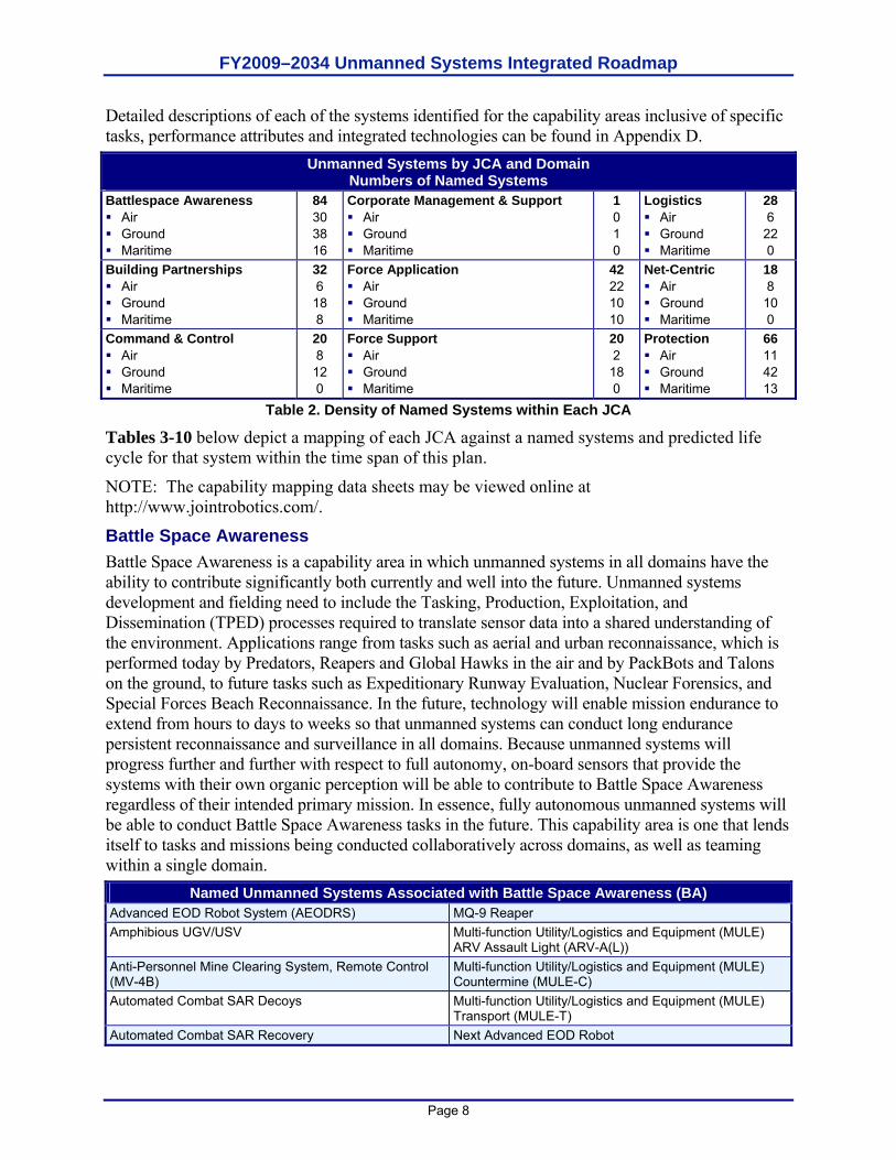
This chapter is based both on what has been officially programmed into the budget across the PB09 as well as what is projected to be feasible beyond the FYDP out to 2034. A working group composed of subject matter experts (SMEs) in the air, ground and maritime domains across the Services and DoD Agencies created this vision collectively. It represents a reasoned projection of how the Department might employ unmanned systems across a variety of mission areas, but it does not imply that decisions have been made to pursue such systems or that funding has been programmed against these projections. The intent of the vision is to articulate the possibilities and subsequently those actions and issues the Department would have to address to bring about such a future. This integrated vision for DoD development and employment of unmanned systems is characterized in three ways. First, unmanned systems (those currently in the inventory, those currently in development, and those projected in the future) are categorized to provide a sense of the types of missions that currently, and in the future could be, supported by unmanned solutions. Next, the level of performance needed by unmanned systems to carry out the identified missions was identified and projected. This “performance envelope” serves as the starting point for understanding the technological, policy, and standardization implications for being able to develop and employ unmanned systems. Finally, having understood the implications associated with the potential future missions and needed performance enhancements, goals and objectives were crafted that will enable the Department to bring the future vision to reality if it chooses to pursue this projected path. These three visionary characterizations for the future of unmanned systems within the Department serve as the underpinnings for the remainder of this Roadmap. Unmanned Systems Applied to Joint Capability Areas (JCAs) Mapping current and projected unmanned systems against the JCAs provides a sense of the Product Line Portfolio of unmanned systems and how it currently and could in the future, contribute to the missions of the Department. Each JCA represents a collection of related missions and tasks that are typically conducted to bring about the desired effects associated with that capability (see Appendix E for complete definitions of capability areas and representative tasks). Since nine JCAs have been defined, assessment identified that unmanned systems had the potential to be key contributors for Battle Space Awareness, Force Application, Protection, Logistics, and Building Partnerships as shown in Table 2 below. The Force Support and Net Centric capability areas had fewer opportunities for unmanned systems to contribute to these types of missions and tasks. Current technology and future advancements can and will enable single platforms to perform a variety of missions across multiple capability areas. This represents an opportunity for the Department to achieve a greater return on investment. Furthermore, the projections show that there will be opportunities for joint systems to conduct missions for each of the Services, just as there will be situations in which domain conditions or Service missions will dictate unique solutions.
FY2009–2034 Unmanned Systems Integrated Roadmap
Page 8
Detailed descriptions of each of the systems identified for the capability areas inclusive of specific tasks, performance attributes and integrated technologies can be found in Appendix D.
Unmanned Systems by JCA and Domain Numbers of Named Systems
Battlespace Awareness Air Ground Maritime
84 30 38 16
Corporate Management & Support Air Ground Maritime
1 0 1 0
Logistics Air Ground Maritime
28 6
22 0
Building Partnerships Air Ground Maritime
32 6 18 8
Force Application Air Ground Maritime
42 22 10 10
Net-Centric Air Ground Maritime
18 8
10 0
Command & Control Air Ground Maritime
20 8 12 0
Force Support Air Ground Maritime
20 2 18 0
Protection Air Ground Maritime
66 11 42 13
Table 2. Density of Named Systems within Each JCA
Tables 3-10 below depict a mapping of each JCA against a named systems and predicted life cycle for that system within the time span of this plan.
NOTE: The capability mapping data sheets may be viewed online at http://www.jointrobotics.com/.
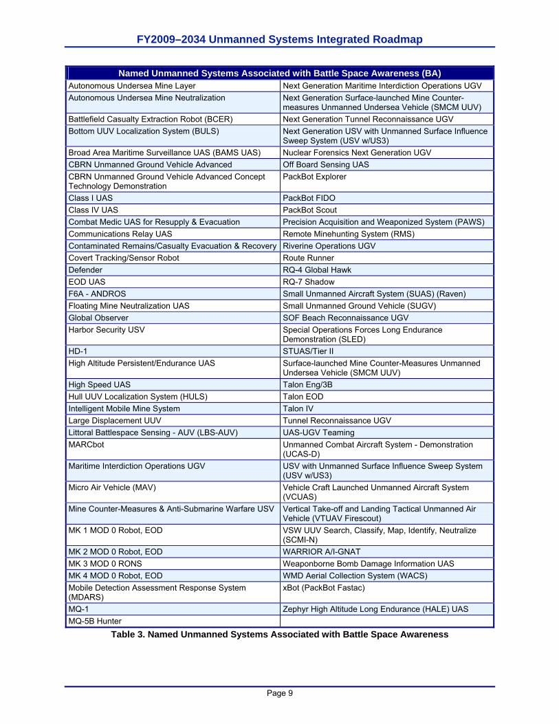
Battle Space Awareness Battle Space Awareness is a capability area in which unmanned systems in all domains have the ability to contribute significantly both currently and well into the future. Unmanned systems development and fielding need to include the Tasking, Production, Exploitation, and Dissemination (TPED) processes required to translate sensor data into a shared understanding of the environment. Applications range from tasks such as aerial and urban reconnaissance, which is performed today by Predators, Reapers and Global Hawks in the air and by PackBots and Talons on the ground, to future tasks such as Expeditionary Runway Evaluation, Nuclear Forensics, and Special Forces Beach Reconnaissance. In the future, technology will enable mission endurance to extend from hours to days to weeks so that unmanned systems can conduct long endurance persistent reconnaissance and surveillance in all domains. Because unmanned systems will progress further and further with respect to full autonomy, on-board sensors that provide the systems with their own organic perception will be able to contribute to Battle Space Awareness regardless of their intended primary mission. In essence, fully autonomous unmanned systems will be able to conduct Battle Space Awareness tasks in the future. This capability area is one that lends itself to tasks and missions being conducted collaboratively across domains, as well as teaming within a single domain.
Named Unmanned Systems Associated with Battle Space Awareness (BA) Advanced EOD Robot System (AEODRS) MQ-9 Reaper Amphibious UGV/USV Multi-function Utility/Logistics and Equipment (MULE)
ARV Assault Light (ARV-A(L)) Anti-Personnel Mine Clearing System, Remote Control (MV-4B)
Multi-function Utility/Logistics and Equipment (MULE) Countermine (MULE-C)
Automated Combat SAR Decoys Multi-function Utility/Logistics and Equipment (MULE) Transport (MULE-T)
Automated Combat SAR Recovery Next Advanced EOD Robot
FY2009–2034 Unmanned Systems Integrated Roadmap
Page 9
Named Unmanned Systems Associated with Battle Space Awareness (BA) Autonomous Undersea Mine Layer Next Generation Maritime Interdiction Operations UGV Autonomous Undersea Mine Neutralization Next Generation Surface-launched Mine Counter-
measures Unmanned Undersea Vehicle (SMCM UUV) Battlefield Casualty Extraction Robot (BCER) Next Generation Tunnel Reconnaissance UGV Bottom UUV Localization System (BULS) Next Generation USV with Unmanned Surface Influence
Sweep System (USV w/US3) Broad Area Maritime Surveillance UAS (BAMS UAS) Nuclear Forensics Next Generation UGV CBRN Unmanned Ground Vehicle Advanced Off Board Sensing UAS CBRN Unmanned Ground Vehicle Advanced Concept Technology Demonstration
PackBot Explorer
Class I UAS PackBot FIDO Class IV UAS PackBot Scout Combat Medic UAS for Resupply & Evacuation Precision Acquisition and Weaponized System (PAWS) Communications Relay UAS Remote Minehunting System (RMS) Contaminated Remains/Casualty Evacuation & Recovery Riverine Operations UGV Covert Tracking/Sensor Robot Route Runner Defender RQ-4 Global Hawk EOD UAS RQ-7 Shadow F6A - ANDROS Small Unmanned Aircraft System (SUAS) (Raven) Floating Mine Neutralization UAS Small Unmanned Ground Vehicle (SUGV) Global Observer SOF Beach Reconnaissance UGV Harbor Security USV Special Operations Forces Long Endurance
Demonstration (SLED) HD-1 STUAS/Tier II High Altitude Persistent/Endurance UAS Surface-launched Mine Counter-Measures Unmanned
Undersea Vehicle (SMCM UUV) High Speed UAS Talon Eng/3B Hull UUV Localization System (HULS) Talon EOD Intelligent Mobile Mine System Talon IV Large Displacement UUV Tunnel Reconnaissance UGV Littoral Battlespace Sensing - AUV (LBS-AUV) UAS-UGV Teaming MARCbot Unmanned Combat Aircraft System - Demonstration
(UCAS-D) Maritime Interdiction Operations UGV USV with Unmanned Surface Influence Sweep System
(USV w/US3) Micro Air Vehicle (MAV) Vehicle Craft Launched Unmanned Aircraft System
(VCUAS) Mine Counter-Measures & Anti-Submarine Warfare USV Vertical Take-off and Landing Tactical Unmanned Air
Vehicle (VTUAV Firescout) MK 1 MOD 0 Robot, EOD VSW UUV Search, Classify, Map, Identify, Neutralize
(SCMI-N) MK 2 MOD 0 Robot, EOD WARRIOR A/I-GNAT MK 3 MOD 0 RONS Weaponborne Bomb Damage Information UAS MK 4 MOD 0 Robot, EOD WMD Aerial Collection System (WACS) Mobile Detection Assessment Response System (MDARS)
xBot (PackBot Fastac)
MQ-1 Zephyr High Altitude Long Endurance (HALE) UAS MQ-5B Hunter
Table 3. Named Unmanned Systems Associated with Battle Space Awareness
FY2009–2034 Unmanned Systems Integrated Roadmap
Page 10
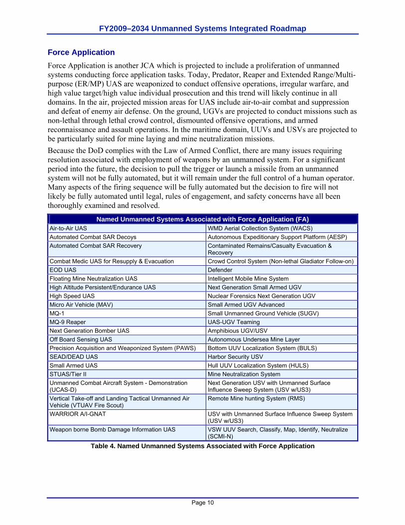
Force Application Force Application is another JCA which is projected to include a proliferation of unmanned systems conducting force application tasks. Today, Predator, Reaper and Extended Range/Multi-purpose (ER/MP) UAS are weaponized to conduct offensive operations, irregular warfare, and high value target/high value individual prosecution and this trend will likely continue in all domains. In the air, projected mission areas for UAS include air-to-air combat and suppression and defeat of enemy air defense. On the ground, UGVs are projected to conduct missions such as non-lethal through lethal crowd control, dismounted offensive operations, and armed reconnaissance and assault operations. In the maritime domain, UUVs and USVs are projected to be particularly suited for mine laying and mine neutralization missions. Because the DoD complies with the Law of Armed Conflict, there are many issues requiring resolution associated with employment of weapons by an unmanned system. For a significant period into the future, the decision to pull the trigger or launch a missile from an unmanned system will not be fully automated, but it will remain under the full control of a human operator. Many aspects of the firing sequence will be fully automated but the decision to fire will not likely be fully automated until legal, rules of engagement, and safety concerns have all been thoroughly examined and resolved.
Named Unmanned Systems Associated with Force Application (FA) Air-to-Air UAS WMD Aerial Collection System (WACS) Automated Combat SAR Decoys Autonomous Expeditionary Support Platform (AESP) Automated Combat SAR Recovery Contaminated Remains/Casualty Evacuation &
Recovery Combat Medic UAS for Resupply & Evacuation Crowd Control System (Non-lethal Gladiator Follow-on) EOD UAS Defender Floating Mine Neutralization UAS Intelligent Mobile Mine System High Altitude Persistent/Endurance UAS Next Generation Small Armed UGV High Speed UAS Nuclear Forensics Next Generation UGV Micro Air Vehicle (MAV) Small Armed UGV Advanced MQ-1 Small Unmanned Ground Vehicle (SUGV) MQ-9 Reaper UAS-UGV Teaming Next Generation Bomber UAS Amphibious UGV/USV Off Board Sensing UAS Autonomous Undersea Mine Layer Precision Acquisition and Weaponized System (PAWS) Bottom UUV Localization System (BULS) SEAD/DEAD UAS Harbor Security USV Small Armed UAS Hull UUV Localization System (HULS) STUAS/Tier II Mine Neutralization System Unmanned Combat Aircraft System - Demonstration (UCAS-D)
Next Generation USV with Unmanned Surface Influence Sweep System (USV w/US3)
Vertical Take-off and Landing Tactical Unmanned Air Vehicle (VTUAV Fire Scout)
Remote Mine hunting System (RMS)
WARRIOR A/I-GNAT USV with Unmanned Surface Influence Sweep System (USV w/US3)
Weapon borne Bomb Damage Information UAS VSW UUV Search, Classify, Map, Identify, Neutralize (SCMI-N)
Table 4. Named Unmanned Systems Associated with Force Application
FY2009–2034 Unmanned Systems Integrated Roadmap
Page 11
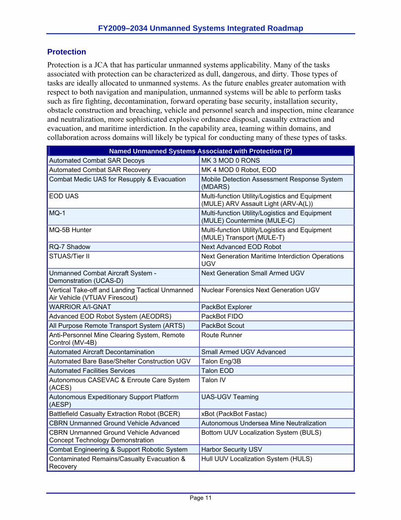
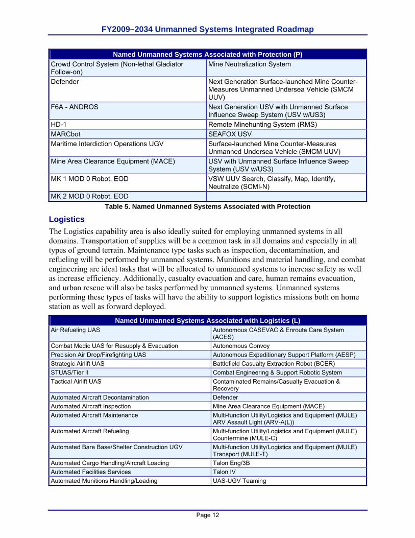
Protection Protection is a JCA that has particular unmanned systems applicability. Many of the tasks associated with protection can be characterized as dull, dangerous, and dirty. Those types of tasks are ideally allocated to unmanned systems. As the future enables greater automation with respect to both navigation and manipulation, unmanned systems will be able to perform tasks such as fire fighting, decontamination, forward operating base security, installation security, obstacle construction and breaching, vehicle and personnel search and inspection, mine clearance and neutralization, more sophisticated explosive ordnance disposal, casualty extraction and evacuation, and maritime interdiction. In the capability area, teaming within domains, and collaboration across domains will likely be typical for conducting many of these types of tasks.
Named Unmanned Systems Associated with Protection (P) Automated Combat SAR Decoys MK 3 MOD 0 RONS Automated Combat SAR Recovery MK 4 MOD 0 Robot, EOD Combat Medic UAS for Resupply & Evacuation Mobile Detection Assessment Response System
(MDARS) EOD UAS Multi-function Utility/Logistics and Equipment
(MULE) ARV Assault Light (ARV-A(L)) MQ-1 Multi-function Utility/Logistics and Equipment
(MULE) Countermine (MULE-C) MQ-5B Hunter Multi-function Utility/Logistics and Equipment
(MULE) Transport (MULE-T) RQ-7 Shadow Next Advanced EOD Robot STUAS/Tier II Next Generation Maritime Interdiction Operations
UGV Unmanned Combat Aircraft System - Demonstration (UCAS-D)
Next Generation Small Armed UGV
Vertical Take-off and Landing Tactical Unmanned Air Vehicle (VTUAV Firescout)
Nuclear Forensics Next Generation UGV
WARRIOR A/I-GNAT PackBot Explorer Advanced EOD Robot System (AEODRS) PackBot FIDO All Purpose Remote Transport System (ARTS) PackBot Scout Anti-Personnel Mine Clearing System, Remote Control (MV-4B)
Route Runner
Automated Aircraft Decontamination Small Armed UGV Advanced Automated Bare Base/Shelter Construction UGV Talon Eng/3B Automated Facilities Services Talon EOD Autonomous CASEVAC & Enroute Care System (ACES)
Talon IV
Autonomous Expeditionary Support Platform (AESP)
UAS-UGV Teaming
Battlefield Casualty Extraction Robot (BCER) xBot (PackBot Fastac) CBRN Unmanned Ground Vehicle Advanced Autonomous Undersea Mine Neutralization CBRN Unmanned Ground Vehicle Advanced Concept Technology Demonstration
Bottom UUV Localization System (BULS)
Combat Engineering & Support Robotic System Harbor Security USV Contaminated Remains/Casualty Evacuation & Recovery
Hull UUV Localization System (HULS)
FY2009–2034 Unmanned Systems Integrated Roadmap
Page 12
Named Unmanned Systems Associated with Protection (P) Crowd Control System (Non-lethal Gladiator Follow-on)
Mine Neutralization System
Defender Next Generation Surface-launched Mine Counter-Measures Unmanned Undersea Vehicle (SMCM UUV)
F6A - ANDROS Next Generation USV with Unmanned Surface Influence Sweep System (USV w/US3)
HD-1 Remote Minehunting System (RMS) MARCbot SEAFOX USV Maritime Interdiction Operations UGV Surface-launched Mine Counter-Measures
Unmanned Undersea Vehicle (SMCM UUV) Mine Area Clearance Equipment (MACE) USV with Unmanned Surface Influence Sweep
System (USV w/US3) MK 1 MOD 0 Robot, EOD VSW UUV Search, Classify, Map, Identify,
Neutralize (SCMI-N) MK 2 MOD 0 Robot, EOD
Table 5. Named Unmanned Systems Associated with Protection
Logistics The Logistics capability area is also ideally suited for employing unmanned systems in all domains. Transportation of supplies will be a common task in all domains and especially in all types of ground terrain. Maintenance type tasks such as inspection, decontamination, and refueling will be performed by unmanned systems. Munitions and material handling, and combat engineering are ideal tasks that will be allocated to unmanned systems to increase safety as well as increase efficiency. Additionally, casualty evacuation and care, human remains evacuation, and urban rescue will also be tasks performed by unmanned systems. Unmanned systems performing these types of tasks will have the ability to support logistics missions both on home station as well as forward deployed.
Named Unmanned Systems Associated with Logistics (L) Air Refueling UAS Autonomous CASEVAC & Enroute Care System
(ACES) Combat Medic UAS for Resupply & Evacuation Autonomous Convoy Precision Air Drop/Firefighting UAS Autonomous Expeditionary Support Platform (AESP) Strategic Airlift UAS Battlefield Casualty Extraction Robot (BCER) STUAS/Tier II Combat Engineering & Support Robotic System Tactical Airlift UAS Contaminated Remains/Casualty Evacuation &
Recovery Automated Aircraft Decontamination Defender Automated Aircraft Inspection Mine Area Clearance Equipment (MACE) Automated Aircraft Maintenance Multi-function Utility/Logistics and Equipment (MULE)
ARV Assault Light (ARV-A(L)) Automated Aircraft Refueling Multi-function Utility/Logistics and Equipment (MULE)
Countermine (MULE-C) Automated Bare Base/Shelter Construction UGV Multi-function Utility/Logistics and Equipment (MULE)
Transport (MULE-T) Automated Cargo Handling/Aircraft Loading Talon Eng/3B Automated Facilities Services Talon IV Automated Munitions Handling/Loading UAS-UGV Teaming
FY2009–2034 Unmanned Systems Integrated Roadmap
Page 13
Table 6. Named Unmanned Systems Associated with Logistics
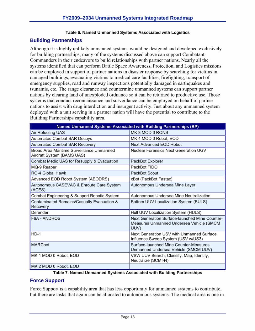
Building Partnerships Although it is highly unlikely unmanned systems would be designed and developed exclusively for building partnerships, many of the systems discussed above can support Combatant Commanders in their endeavors to build relationships with partner nations. Nearly all the systems identified that can perform Battle Space Awareness, Protection, and Logistics missions can be employed in support of partner nations in disaster response by searching for victims in damaged buildings, evacuating victims to medical care facilities, firefighting, transport of emergency supplies, road and runway inspections potentially damaged in earthquakes and tsunamis, etc. The range clearance and countermine unmanned systems can support partner nations by clearing land of unexploded ordnance so it can be returned to productive use. Those systems that conduct reconnaissance and surveillance can be employed on behalf of partner nations to assist with drug interdiction and insurgent activity. Just about any unmanned system deployed with a unit serving in a partner nation will have the potential to contribute to the Building Partnerships capability area.
Named Unmanned Systems Associated with Building Partnerships (BP) Air Refueling UAS MK 3 MOD 0 RONS Automated Combat SAR Decoys MK 4 MOD 0 Robot, EOD Automated Combat SAR Recovery Next Advanced EOD Robot Broad Area Maritime Surveillance Unmanned Aircraft System (BAMS UAS)
Nuclear Forensics Next Generation UGV
Combat Medic UAS for Resupply & Evacuation PackBot Explorer MQ-9 Reaper PackBot FIDO RQ-4 Global Hawk PackBot Scout Advanced EOD Robot System (AEODRS) xBot (PackBot Fastac) Autonomous CASEVAC & Enroute Care System (ACES)
Autonomous Undersea Mine Layer
Combat Engineering & Support Robotic System Autonomous Undersea Mine Neutralization Contaminated Remains/Casualty Evacuation & Recovery
Bottom UUV Localization System (BULS)
Defender Hull UUV Localization System (HULS) F6A - ANDROS Next Generation Surface-launched Mine Counter-
Measures Unmanned Undersea Vehicle (SMCM UUV)
HD-1 Next Generation USV with Unmanned Surface Influence Sweep System (USV w/US3)
MARCbot Surface-launched Mine Counter-Measures Unmanned Undersea Vehicle (SMCM UUV)
MK 1 MOD 0 Robot, EOD VSW UUV Search, Classify, Map, Identify, Neutralize (SCMI-N)
MK 2 MOD 0 Robot, EOD Table 7. Named Unmanned Systems Associated with Building Partnerships
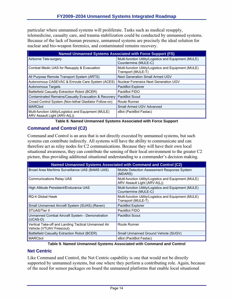
Force Support Force Support is a capability area that has less opportunity for unmanned systems to contribute, but there are tasks that again can be allocated to autonomous systems. The medical area is one in
FY2009–2034 Unmanned Systems Integrated Roadmap
Page 14
particular where unmanned systems will proliferate. Tasks such as medical resupply, telemedicine, casualty care, and trauma stabilization could be conducted by unmanned systems. Because of the lack of human presence, unmanned systems are precisely the ideal solution for nuclear and bio-weapon forensics, and contaminated remains recovery.
Named Unmanned Systems Associated with Force Support (FS) Airborne Tele-surgery Multi-function Utility/Logistics and Equipment (MULE)
Countermine (MULE-C) Combat Medic UAS for Resupply & Evacuation Multi-function Utility/Logistics and Equipment (MULE)
Transport (MULE-T) All Purpose Remote Transport System (ARTS) Next Generation Small Armed UGV Autonomous CASEVAC & Enroute Care System (ACES) Nuclear Forensics Next Generation UGV Autonomous Targets PackBot Explorer Battlefield Casualty Extraction Robot (BCER) PackBot FIDO Contaminated Remains/Casualty Evacuation & Recovery PackBot Scout Crowd Control System (Non-lethal Gladiator Follow-on) Route Runner MARCbot Small Armed UGV Advanced Multi-function Utility/Logistics and Equipment (MULE) ARV Assault Light (ARV-A(L))
xBot (PackBot Fastac)
Table 8. Named Unmanned Systems Associated with Force Support
Command and Control (C2) Command and Control is an area that is not directly executed by unmanned systems, but such systems can contribute indirectly. All systems will have the ability to communicate and can therefore act as relay nodes for C2 communications. Because they will have their own local situational awareness, they can contribute the sensing of their local environment to the greater C2 picture, thus providing additional situational understanding to a commander’s decision making.
Named Unmanned Systems Associated with Command and Control (C2) Broad Area Maritime Surveillance UAS (BAMS UAS) Mobile Detection Assessment Response System
(MDARS) Communications Relay UAS Multi-function Utility/Logistics and Equipment (MULE)
ARV Assault Light (ARV-A(L)) High Altitude Persistent/Endurance UAS Multi-function Utility/Logistics and Equipment (MULE)
Countermine (MULE-C) RQ-4 Global Hawk Multi-function Utility/Logistics and Equipment (MULE)
Transport (MULE-T) Small Unmanned Aircraft System (SUAS) (Raven) PackBot Explorer STUAS/Tier II PackBot FIDO Unmanned Combat Aircraft System - Demonstration (UCAS-D)
PackBot Scout
Vertical Take-off and Landing Tactical Unmanned Air Vehicle (VTUAV Firescout)
Route Runner
Battlefield Casualty Extraction Robot (BCER) Small Unmanned Ground Vehicle (SUGV) MARCbot xBot (PackBot Fastac)
Table 9. Named Unmanned Systems Associated with Command and Control
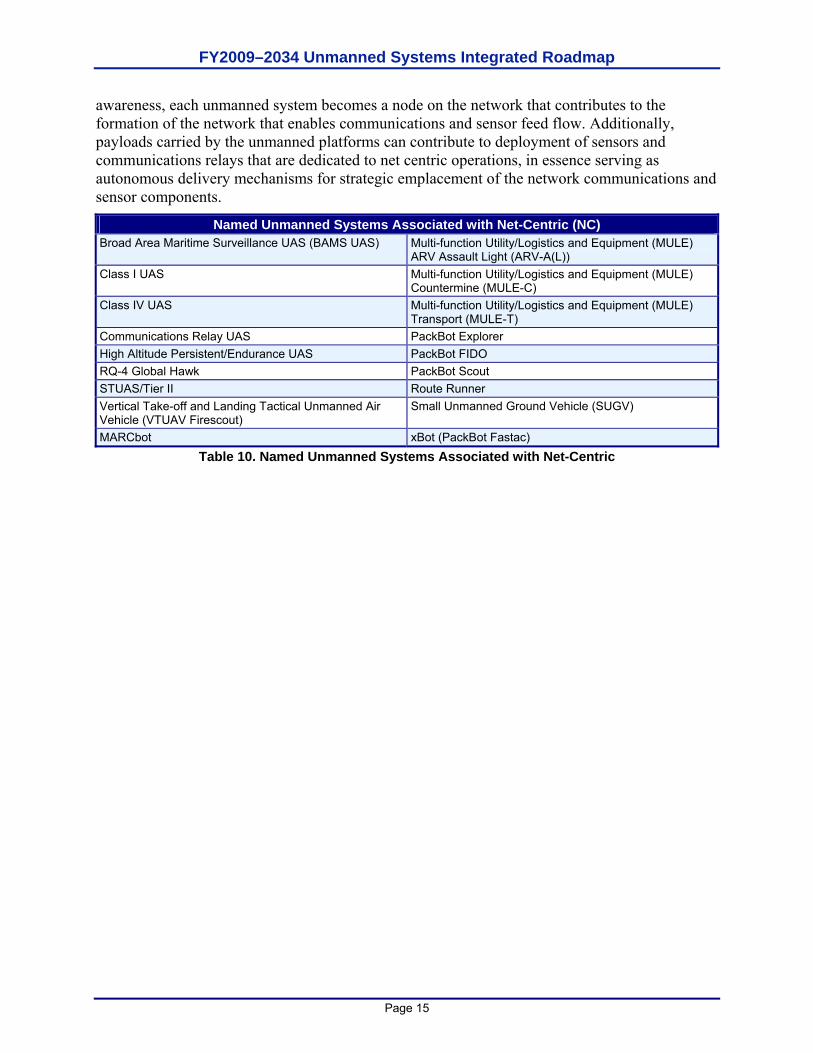
Net Centric Like Command and Control, the Net Centric capability is one that would not be directly supported by unmanned systems, but one where they perform a contributing role. Again, because of the need for sensor packages on board the unmanned platforms that enable local situational
FY2009–2034 Unmanned Systems Integrated Roadmap
Page 15
awareness, each unmanned system becomes a node on the network that contributes to the formation of the network that enables communications and sensor feed flow. Additionally, payloads carried by the unmanned platforms can contribute to deployment of sensors and communications relays that are dedicated to net centric operations, in essence serving as autonomous delivery mechanisms for strategic emplacement of the network communications and sensor components.
Named Unmanned Systems Associated with Net-Centric (NC) Broad Area Maritime Surveillance UAS (BAMS UAS) Multi-function Utility/Logistics and Equipment (MULE)
ARV Assault Light (ARV-A(L)) Class I UAS Multi-function Utility/Logistics and Equipment (MULE)
Countermine (MULE-C) Class IV UAS Multi-function Utility/Logistics and Equipment (MULE)
Transport (MULE-T) Communications Relay UAS PackBot Explorer High Altitude Persistent/Endurance UAS PackBot FIDO RQ-4 Global Hawk PackBot Scout STUAS/Tier II Route Runner Vertical Take-off and Landing Tactical Unmanned Air Vehicle (VTUAV Firescout)
Small Unmanned Ground Vehicle (SUGV)
MARCbot xBot (PackBot Fastac) Table 10. Named Unmanned Systems Associated with Net-Centric

FY2009–2034 Unmanned Systems Integrated Roadmap
Page 16
This page is intentionally left blank.
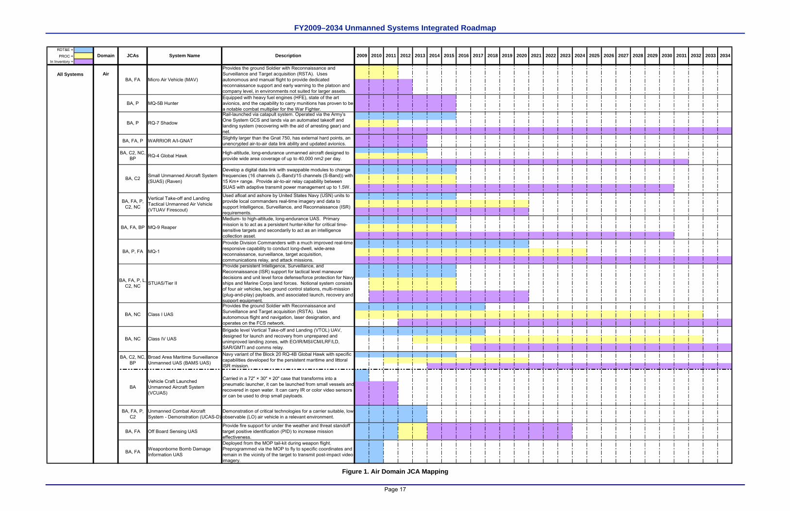
FY2009–2034 Unmanned Systems Integrated Roadmap
Page 17
RDT&E =
PROC =In Inventory =
Air
BA, P MQ-5B HunterEquipped with heavy fuel engines (HFE), state of the art avionics, and the capability to carry munitions has proven to be a notable combat multiplier for the War Fighter.
BA, FA, P WARRIOR A/I-GNAT Slightly larger than the Gnat 750, has external hard points, an unencrypted air-to-air data link ability and updated avionics.
BA, FA, P, C2
Unmanned Combat Aircraft System - Demonstration (UCAS-D)
Demonstration of critical technologies for a carrier suitable, low observable (LO) air vehicle in a relevant environment.
BA, FA Off Board Sensing UASProvide fire support for under the weather and threat standoff target positive identification (PID) to increase mission effectiveness.
BA, FA Weaponborne Bomb Damage Information UAS
Deployed from the MOP tail-kit during weapon flight. Preprogrammed via the MOP to fly to specific coordinates and remain in the vicinity of the target to transmit post-impact video imagery.
2018 2031 2033
BA, FA, P, C2, NC
Used afloat and ashore by United States Navy (USN) units to provide local commanders real-time imagery and data to support Intelligence, Surveillance, and Reconnaissance (ISR) requirements.
JCAs 20232015 20342016 20172012 2013 2014
All Systems
Description 203020262009 2028 20292024 20252022 2032System NameDomain 20272010 2011 20202019 2021
Vertical Take-off and Landing Tactical Unmanned Air Vehicle (VTUAV Firescout)
BA, C2, NC, BP
High-altitude, long-endurance unmanned aircraft designed to provide wide area coverage of up to 40,000 nm2 per day.
BA, C2
Develop a digital data link with swappable modules to change frequencies (16 channels (L-Band)/15 channels (S-Band)) with 15 Km+ range. Provide air-to-air relay capability between SUAS with adaptive transmit power management up to 1.5W.
RQ-4 Global Hawk
Small Unmanned Aircraft System (SUAS) (Raven)
BA, FA, BP
Medium- to high-altitude, long-endurance UAS. Primary mission is to act as a persistent hunter-killer for critical time-sensitive targets and secondarily to act as an intelligence collection asset.
MQ-9 Reaper
MQ-1
Brigade level Vertical Take-off and Landing (VTOL) UAV, designed for launch and recovery from unprepared and unimproved landing zones, with EO/IR/MSI/CM/LRF/LD, SAR/GMTI and comms relay.
BA, P, FA
Provide Division Commanders with a much improved real-time responsive capability to conduct long-dwell, wide-area reconnaissance, surveillance, target acquisition, communications relay, and attack missions.
Class IV UAS
BA, FA, P, L, C2, NC
Provide persistent Intelligence, Surveillance, and Reconnaissance (ISR) support for tactical level maneuver decisions and unit level force defense/force protection for Navy ships and Marine Corps land forces. Notional system consists of four air vehicles, two ground control stations, multi-mission (plug-and-play) payloads, and associated launch, recovery and support equipment.
STUAS/Tier II
BA, FA
Provides the ground Soldier with Reconnaissance and Surveillance and Target acquisition (RSTA). Uses autonomous and manual flight to provide dedicated reconnaissance support and early warning to the platoon and company level, in environments not suited for larger assets.
Micro Air Vehicle (MAV)
BA, P RQ-7 Shadow
Rail-launched via catapult system. Operated via the Army’s One System GCS and lands via an automated takeoff and landing system (recovering with the aid of arresting gear) and net.
BA, NC Class I UAS
Provides the ground Soldier with Reconnaissance and Surveillance and Target acquisition (RSTA). Uses autonomous flight and navigation, laser designation, and operates on the FCS network.
BA, NC
BA, C2, NC, BP
Broad Area Maritime Surveillance Unmanned UAS (BAMS UAS)
Navy variant of the Block 20 RQ-4B Global Hawk with specific capabilities developed for the persistent maritime and littoral ISR mission.
BAVehicle Craft Launched Unmanned Aircraft System (VCUAS)
Carried in a 72″ × 30″ × 20″ case that transforms into a pneumatic launcher, it can be launched from small vessels and recovered in open water. It can carry IR or color video sensors or can be used to drop small payloads.
Figure 1. Air Domain JCA Mapping
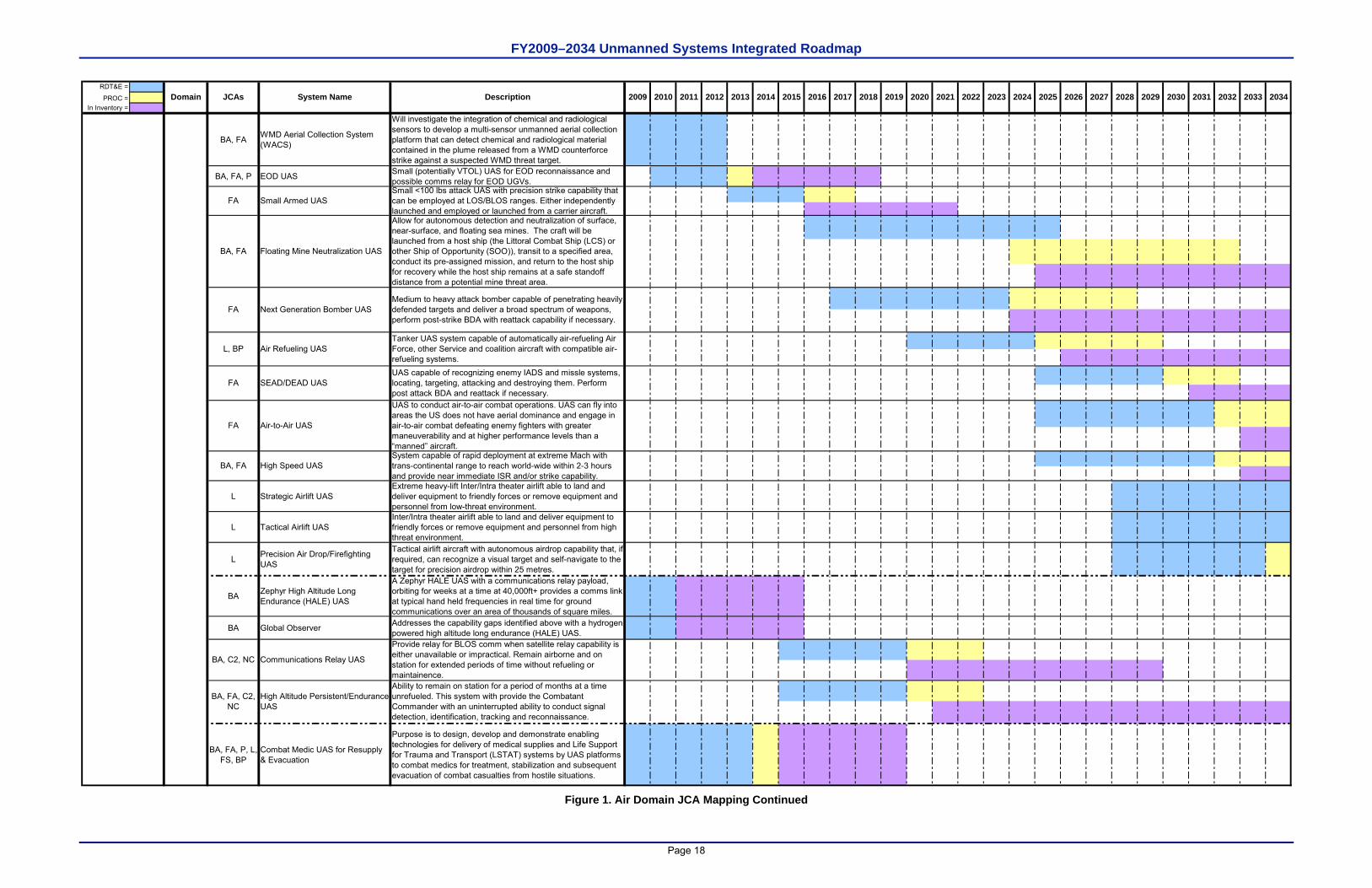
FY2009–2034 Unmanned Systems Integrated Roadmap
Page 18
RDT&E =
PROC =In Inventory =
BA, FA WMD Aerial Collection System (WACS)
Will investigate the integration of chemical and radiological sensors to develop a multi-sensor unmanned aerial collection platform that can detect chemical and radiological material contained in the plume released from a WMD counterforce strike against a suspected WMD threat target.
BA, FA, P EOD UAS Small (potentially VTOL) UAS for EOD reconnaissance and possible comms relay for EOD UGVs.
L Strategic Airlift UASExtreme heavy-lift Inter/Intra theater airlift able to land and deliver equipment to friendly forces or remove equipment and personnel from low-threat environment.
L Tactical Airlift UASInter/Intra theater airlift able to land and deliver equipment to friendly forces or remove equipment and personnel from high threat environment.
L Precision Air Drop/Firefighting UAS
Tactical airlift aircraft with autonomous airdrop capability that, if required, can recognize a visual target and self-navigate to the target for precision airdrop within 25 metres.
BA Zephyr High Altitude Long Endurance (HALE) UAS
A Zephyr HALE UAS with a communications relay payload, orbiting for weeks at a time at 40,000ft+ provides a comms link at typical hand held frequencies in real time for ground communications over an area of thousands of square miles.
BA Global Observer Addresses the capability gaps identified above with a hydrogen powered high altitude long endurance (HALE) UAS.
BA, FA, P, L, FS, BP
Combat Medic UAS for Resupply & Evacuation
Purpose is to design, develop and demonstrate enabling technologies for delivery of medical supplies and Life Support for Trauma and Transport (LSTAT) systems by UAS platforms to combat medics for treatment, stabilization and subsequent evacuation of combat casualties from hostile situations.
System capable of rapid deployment at extreme Mach with trans-continental range to reach world-wide within 2-3 hours and provide near immediate ISR and/or strike capability.
BA, C2, NC Communications Relay UAS
Provide relay for BLOS comm when satellite relay capability is either unavailable or impractical. Remain airborne and on station for extended periods of time without refueling or maintainence.
Tanker UAS system capable of automatically air-refueling Air Force, other Service and coalition aircraft with compatible air-refueling systems.
FA Air-to-Air UAS
UAS to conduct air-to-air combat operations. UAS can fly into areas the US does not have aerial dominance and engage in air-to-air combat defeating enemy fighters with greater maneuverability and at higher performance levels than a “manned” aircraft.
L, BP Air Refueling UAS
Small <100 lbs attack UAS with precision strike capability that can be employed at LOS/BLOS ranges. Either independently launched and employed or launched from a carrier aircraft.
UAS capable of recognizing enemy IADS and missle systems, locating, targeting, attacking and destroying them. Perform post attack BDA and reattack if necessary.
SEAD/DEAD UASFA
BA, FA High Speed UAS
BA, FA, C2, NC
High Altitude Persistent/Endurance UAS
Ability to remain on station for a period of months at a time unrefueled. This system with provide the Combatant Commander with an uninterrupted ability to conduct signal detection, identification, tracking and reconnaissance.
Allow for autonomous detection and neutralization of surface, near-surface, and floating sea mines. The craft will be launched from a host ship (the Littoral Combat Ship (LCS) or other Ship of Opportunity (SOO)), transit to a specified area, conduct its pre-assigned mission, and return to the host ship for recovery while the host ship remains at a safe standoff distance from a potential mine threat area.
BA, FA
Small Armed UAS
2032System NameDomain Description 203020262009 2028 20292024 20252022 20272010 2011 20202019 20212012 2013 2014
Medium to heavy attack bomber capable of penetrating heavily defended targets and deliver a broad spectrum of weapons, perform post-strike BDA with reattack capability if necessary.
FA
Floating Mine Neutralization UAS
Next Generation Bomber UASFA
JCAs 20232015 20342016 2017 2018 2031 2033
Figure 1. Air Domain JCA Mapping Continued
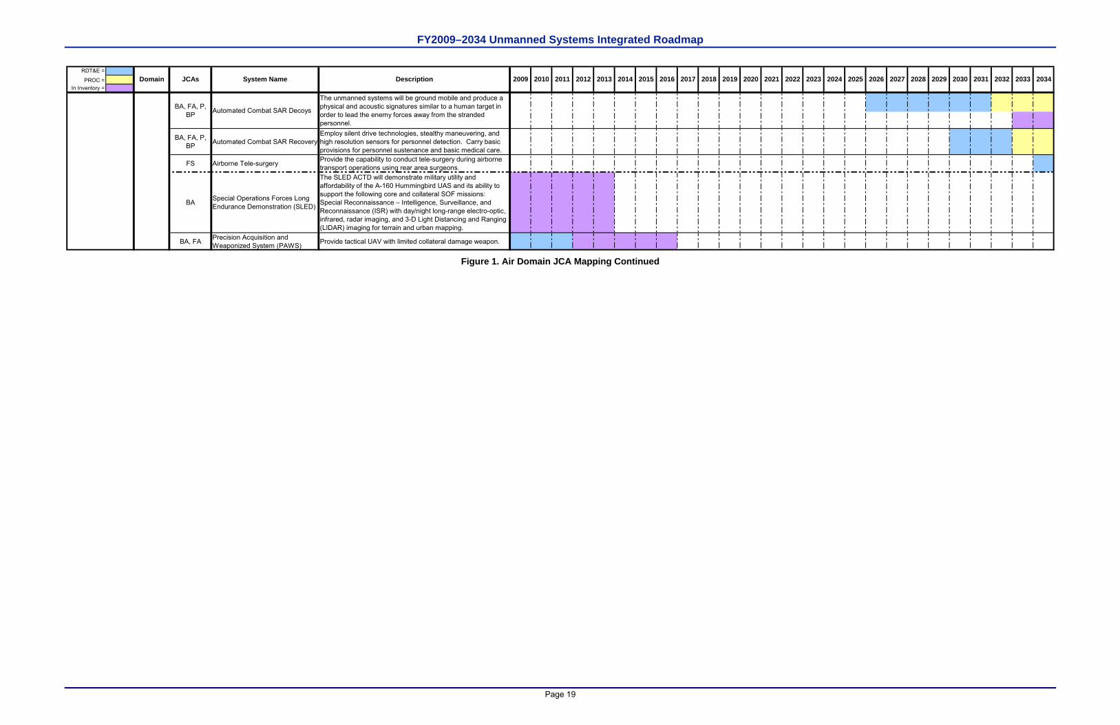
FY2009–2034 Unmanned Systems Integrated Roadmap
Page 19
RDT&E =
PROC =In Inventory =
BA, FA, P, BP Automated Combat SAR Recovery
Employ silent drive technologies, stealthy maneuvering, and high resolution sensors for personnel detection. Carry basic provisions for personnel sustenance and basic medical care.
FS Airborne Tele-surgery Provide the capability to conduct tele-surgery during airborne transport operations using rear area surgeons.
BA Special Operations Forces Long Endurance Demonstration (SLED)
The SLED ACTD will demonstrate military utility and affordability of the A-160 Hummingbird UAS and its ability to support the following core and collateral SOF missions: Special Reconnaissance – Intelligence, Surveillance, and Reconnaissance (ISR) with day/night long-range electro-optic, infrared, radar imaging, and 3-D Light Distancing and Ranging (LIDAR) imaging for terrain and urban mapping.
BA, FA Precision Acquisition and Weaponized System (PAWS) Provide tactical UAV with limited collateral damage weapon.
BA, FA, P, BP
The unmanned systems will be ground mobile and produce a physical and acoustic signatures similar to a human target in order to lead the enemy forces away from the stranded personnel.
2032System NameDomain Description 203020262009 2028 20292024 20252022 20272010 2011 20202019 20212012 2013 2014
Automated Combat SAR Decoys
JCAs 20232015 20342016 2017 2018 2031 2033
Figure 1. Air Domain JCA Mapping Continued

FY2009–2034 Unmanned Systems Integrated Roadmap
Page 20
This page is intentionally left blank.
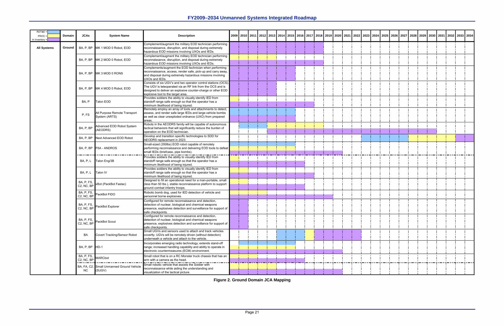
FY2009–2034 Unmanned Systems Integrated Roadmap
Page 21
RDT&E =
PROC =In Inventory =
Ground BA, P, BP MK 1 MOD 0 Robot, EODComplement/augment the military EOD technician performing reconnaissance, disruption, and disposal during extremely hazardous EOD missions involving UXOs and IEDs.
BA, P, BP MK 3 MOD 0 RONS
Complements/augment the EOD technician when performing reconnaissance, access, render safe, pick-up and carry away, and disposal during extremely hazardous missions involving UXOs and IEDs.
BA, P, BP MK 4 MOD 0 Robot, EOD
Consists of six UGV’s and two operator control stations (OCS). The UGV is teleoperated via an RF link from the OCS and is designed to deliver an explosive counter-charge or other EOD explosive tool to the target area.
BA, P, BP Next Advanced EOD Robot Develop and transition specific technologies to SDD for AEODRS replacement in 2023.
BA, P, FS, C2, NC, BP PackBot Explorer
Configured for remote reconnaissance and detection, detection of nuclear, biological and chemical weapons presence, explosives detection and surveillance for support of safe checkpoints.
BA, P, FS, C2, NC, BP PackBot Scout
Configured for remote reconnaissance and detection, detection of nuclear, biological and chemical weapons presence, explosives detection and surveillance for support of safe checkpoints.
BA Covert Tracking/Sensor RobotSmall UGVs and sensors used to attach and track vehicles covertly. UGVs will be remotely driven (without detection) underneath a vehicle and attach to the vehicle.
All Systems
20332027 2028 20292024JCAs 20232015 20342016 2017 2018 20312022 2025 2032System NameDomain Description 203020262009 2010 2011 20202019 20212012 2013 2014
BA, P, BP MK 2 MOD 0 Robot, EODComplement/augment the military EOD technician performing reconnaissance, disruption, and disposal during extremely hazardous EOD missions involving UXOs and IEDs.
BA, P Talon EODProvides soldiers the ability to visually identify IED from standoff range safe enough so that the operator has a minimum likelihood of being injured.
P, FS All Purpose Remote Transport System (ARTS)
Remotely employ an array of tools and attachments to detect, assess, and render safe large IEDs and large-vehicle bombs as well as clear unexploded ordnance (UXO) from prepared areas.
BA, P, BP Advanced EOD Robot System (AEODRS)
Robots in the AEODRS family will be capable of autonomous tactical behaviors that will significantly reduce the burden of operation on the EOD technician.
BA, P, BP F6A - ANDROSSmall-sized (350lbs) EOD robot capable of remotely performing reconnaissance and delivering EOD tools to defeat small IEDs (briefcase, pipe bombs).
BA, P, L Talon Eng/3BProvides soldiers the ability to visually identify IED from standoff range safe enough so that the operator has a minimum likelihood of being injured.
BA, P, L Talon IVProvides soldiers the ability to visually identify IED from standoff range safe enough so that the operator has a minimum likelihood of being injured.
BA, P, FS, C2, NC, BP xBot (PackBot Fastac)
Designed to fill an operational need for a man-portable, small (less than 50 lbs.), stable reconnaissance platform to support ground combat infantry troops.
BA, P, FS, C2, NC, BP PackBot FIDO Robotic bomb dog, used for IED detection of vehicle and
personnel borne explosives.
BA, P, BP HD-1Incorporates emerging radio technology; extends stand-off range; increased handling capability and ability to operate in electronic countermeasures (ECM) environment.
BA, P, FS, C2, NC, BP MARCbot Small robot that is on a RC Monster truck chassis that has an
arm with a camera as the head.
BA, FA, C2, NC
Small Unmanned Ground Vehicle (SUGV)
Small robotic vehicle that assists the Soldier with reconnaissance while aiding the understanding and visualization of the tactical picture.
Figure 2. Ground Domain JCA Mapping
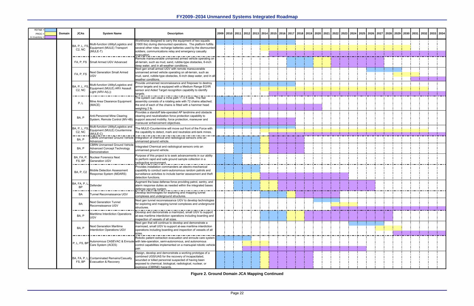
FY2009–2034 Unmanned Systems Integrated Roadmap
Page 22
RDT&E =
PROC =In Inventory =
FA, P, FS Small Armed UGV AdvancedRemote maneuverable unmanned armed vehicle operating on all-terrain, such as mud, sand, rubble-type obstacles, 6-inch deep water, and in all-weather conditions.
BA, P CBRN Unmanned Ground Vehicle Advanced
Integration of chemical and radiological sensors onto an unmanned ground vehicle.
BA, PCBRN Unmanned Ground Vehicle Advanced Concept Technology Demonstration
Integrated Chemical and radiological sensors onto an unmanned ground vehicle.
BA, FA, P, FS, BP
Nuclear Forensics Next Generation UGV
Purpose of this project is to seek advancements in our ability to perform rapid and safe ground sample collection in a radioactive environment.
BA, FA, P, L, BP Defender
Augment the base defense force providing patrol, sentry, and alarm response duties as needed within the integrated bases defense security system.
BA Tunnel Reconnaissance UGV Develop technologies for exploring and mapping tunnel complexes and underground structures.
BA, P Martitime Interdiction Operations UGV
Develop and demonstrate a marinized, small UGV to support at-sea maritime interdiction operations including boarding and inspection of vessels of all sizes.
BA, FA, P, L, FS, BP
Contaminated Remains/Casualty Evacuation & Recovery
Design, develop and demonstrate a working prototype of a combined UGS/UAS for the recovery of incapacitated, wounded or killed personnel suspected of having been exposed to chemical, biological, radiological, nuclear, or explosive (CBRNE) hazards.
P, L, FS, BP Autonomous CASEVAC & Enroute Care System (ACES)
Robotic patient extraction evacuation and enroute care system with tele-operation, semi-autonomous, and autonomous control capabilities implemented on a marsupial robotic vehicle pair.
BA Next Generation Tunnel Reconnaissance UGV
Next gen tunnel reconnaissance UGV to develop technologies for exploring and mapping tunnel complexes and underground structures.
BA, P Next Generation Maritime Interdiction Operations UGV
Next gen that will continue to develop and demonstrate a marinized, small UGV to support at-sea maritime interdiction operations including boarding and inspection of vessels of all sizes.
2033
Mobile Detection Assessment Response System (MDARS)
Provides installation commanders an electro-mechanical capability to conduct semi-autonomous random patrols and surveillance activities to include barrier assessment and theft detection functions.
BA, P, C2
Anti-Personnel Mine Clearing System, Remote Control (MV-4B)
The MULE-Countermine will move out front of the Force with the capability to detect, mark and neutralize anti-tank mines.
2027 2028 20292024JCAs 20232015 20342016 2017 2018 20312022 2025 2032System NameDomain Description 203020262009 2010 2011 20202019 20212012 2013 2014
P, L Mine Area Clearance Equipment (MACE)
The system can clear a mine path 11.5 ft wide. The flail assembly consists of a rotating axle with 72 chains attached; the end of each of the chains is fitted with a hammer head weighing 2 lb.
BA, P
Provides a standoff tele-operated AP landmine and obstacle clearing and neutralization force protection capability to support assured mobility, force protection, maneuver and maneuver enhancement objectives.
BA, P, L, FS, C2, NC
Multi-function Utility/Logistics and Equipment (MULE) Countermine (MULE-C)
FA, P, FS Next Generation Small Armed UGV
Next gen small armed UGV with remote maneuverable unmanned armed vehicle operating on all-terrain, such as mud, sand, rubble-type obstacles, 6-inch deep water, and in all-weather conditions.
Multi-function Utility/Logistics and Equipment (MULE) ARV Assault Light (ARV-A(L))
Provide unmanned reconnaissance and firepower to destroy armor targets and is equipped with a Medium Range EO/IR sensor and Aided Target recognition capability to identify targets.
BA, P, L, FS, C2, NC
BA, P, L, FS, C2, NC
Multi-function Utility/Logistics and Equipment (MULE) Transport (MULE-T)
Workhorse designed to carry the equipment of two squads (1900 lbs) during dismounted operations. The platform fulfills several other roles: recharge batteries used by the dismounted soldiers, communications relay and emergency casualty evacuation.
Figure 2. Ground Domain JCA Mapping Continued
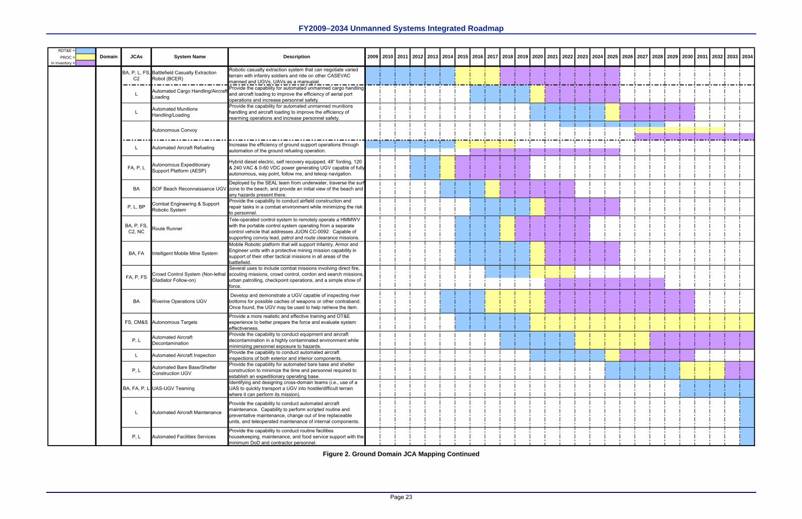
FY2009–2034 Unmanned Systems Integrated Roadmap
Page 23
RDT&E =
PROC =In Inventory =
BA, P, L, FS, C2
Battlefield Casualty Extraction Robot (BCER)
Robotic casualty extraction system that can negotiate varied terrain with infantry soldiers and ride on other CASEVAC manned and UGVs, UAVs as a marsupial.
L Automated Cargo Handling/Aircraft Loading
Provide the capability for automated unmanned cargo handling and aircraft loading to improve the efficiency of aerial port operations and increase personnel safety.
L Automated Munitions Handling/Loading
Provide the capability for automated unmanned munitions handling and aircraft loading to improve the efficiency of rearming operations and increase personnel safety.
FA, P, L Autonomous Expeditionary Support Platform (AESP)
Hybrid diesel electric, self recovery equipped, 48” fording, 120 & 240 VAC & 0-60 VDC power generating UGV capable of fully autonomous, way point, follow me, and teleop navigation.
BA SOF Beach Reconnaissance UGVDeployed by the SEAL team from underwater, traverse the surf zone to the beach, and provide an initial view of the beach and any hazards present there.
P, L, BP Combat Engineering & Support Robotic System
Provide the capability to conduct airfield construction and repair tasks in a combat environment while minimizing the risk to personnel.
BA, P, FS, C2, NC Route Runner
Tele-operated control system to remotely operate a HMMWV with the portable control system operating from a separate control vehicle that addresses JUON CC-0092. Capable of supporting convoy lead, patrol and route clearance missions.
BA, FA Intelligent Mobile Mine System
Mobile Robotic platform that will support Infantry, Armor and Engineer units with a protective mining mission capability in support of their other tactical missions in all areas of the battlefield.
BA Riverine Operations UGV Develop and demonstrate a UGV capable of inspecting river bottoms for possible caches of weapons or other contraband. Once found, the UGV may be used to help retrieve the item.
FS, CM&S Autonomous TargetsProvide a more realistic and effective training and OT&E experience to better prepare the force and evaluate system effectiveness.
P, L Automated Aircraft Decontamination
Provide the capability to conduct equipment and aircraft decontamination in a highly contaminated environment while minimizing personnel exposure to hazards.
L Automated Aircraft Inspection Provide the capability to conduct automated aircraft inspections of both exterior and interior components.
P, L Automated Bare Base/Shelter Construction UGV
Provide the capability for automated bare base and shelter construction to minimize the time and personnel required to establish an expeditionary operating base.
BA, FA, P, L UAS-UGV TeamingIdentifying and designing cross-domain teams (i.e., use of a UAS to quickly transport a UGV into hostile/difficult terrain where it can perform its mission).
L Automated Aircraft Maintenance
Provide the capability to conduct automated aircraft maintenance. Capability to perform scripted routine and preventative maintenance, change out of line replaceable units, and teleoperated maintenance of internal components.
P, L Automated Facilities ServicesProvide the capability to conduct routine facilities housekeeping, maintenance, and food service support with the minimum DoD and contractor personnel.
FA, P, FS Crowd Control System (Non-lethal Gladiator Follow-on)
Several uses to include combat missions involving direct fire, scouting missions, crowd control, cordon and search missions, urban patrolling, checkpoint operations, and a simple show of force.
L Increase the efficiency of ground support operations through automation of the ground refueling operation.Automated Aircraft Refueling
20332027 2028 20292024JCAs 20232015 20342016 2017 2018 20312022 2025 2032System NameDomain Description 203020262009 2010 2011 20202019 20212012 2013 2014
Autonomous Convoy
Figure 2. Ground Domain JCA Mapping Continued
FY2009–2034 Unmanned Systems Integrated Roadmap
Page 24
This page is intentionally left blank.
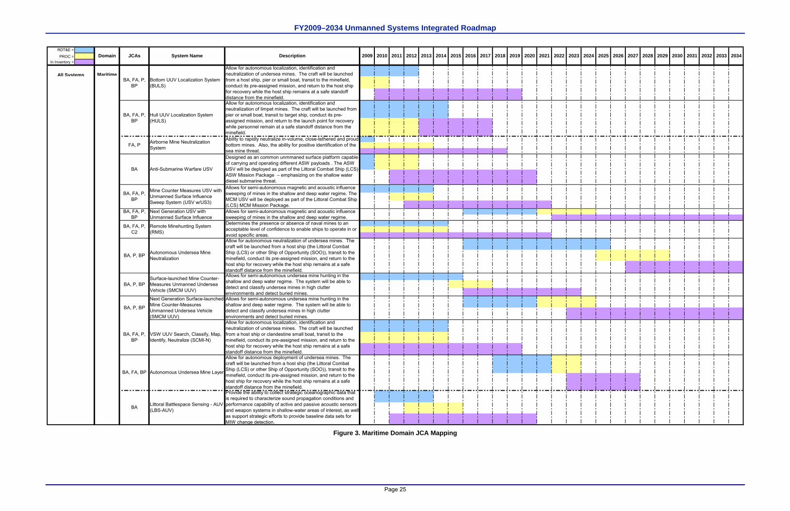
FY2009–2034 Unmanned Systems Integrated Roadmap
Page 25
RDT&E =
PROC =In Inventory =
MaritimeAll Systems
Allows for semi-autonomous undersea mine hunting in the shallow and deep water regime. The system will be able to detect and classify undersea mines in high clutter environments and detect buried mines.
Allow for autonomous deployment of undersea mines. The craft will be launched from a host ship (the Littoral Combat Ship (LCS) or other Ship of Opportunity (SOO)), transit to the minefield, conduct its pre-assigned mission, and return to the host ship for recovery while the host ship remains at a safe standoff distance from the minefield.
BA, FA, P, BP
VSW UUV Search, Classify, Map, Identify, Neutralize (SCMI-N)
Allow for autonomous localization, identification and neutralization of undersea mines. The craft will be launched from a host ship or clandestine small boat, transit to the minefield, conduct its pre-assigned mission, and return to the host ship for recovery while the host ship remains at a safe standoff distance from the minefield.
BA, FA, BP Autonomous Undersea Mine Layer
Next Generation Surface-launched Mine Counter-Measures Unmanned Undersea Vehicle (SMCM UUV)
BA, P, BPSurface-launched Mine Counter-Measures Unmanned Undersea Vehicle (SMCM UUV)
BA Littoral Battlespace Sensing - AUV (LBS-AUV)
Provide the ability to collect strategic oceanographic data that is required to characterize sound propagation conditions and performance capability of active and passive acoustic sensors and weapon systems in shallow-water areas of interest, as well as support strategic efforts to provide baseline data sets for MIW change detection.
Allows for semi-autonomous undersea mine hunting in the shallow and deep water regime. The system will be able to detect and classify undersea mines in high clutter environments and detect buried mines.
BA, P, BP
BA, FA, P, C2
Remote Minehunting System (RMS)
Determines the presence or absence of naval mines to an acceptable level of confidence to enable ships to operate in or avoid specific areas.
BA, P, BP Autonomous Undersea Mine Neutralization
Allow for autonomous neutralization of undersea mines. The craft will be launched from a host ship (the Littoral Combat Ship (LCS) or other Ship of Opportunity (SOO)), transit to the minefield, conduct its pre-assigned mission, and return to the host ship for recovery while the host ship remains at a safe standoff distance from the minefield.
BA, FA, P, BP
Mine Counter Measures USV with Unmanned Surface Influence Sweep System (USV w/US3)
Allows for semi-autonomous magnetic and acoustic influence sweeping of mines in the shallow and deep water regime. The MCM USV will be deployed as part of the Littoral Combat Ship (LCS) MCM Mission Package.
BA, FA, P, BP
Next Generation USV with Unmanned Surface Influence
Allows for semi-autonomous magnetic and acoustic influence sweeping of mines in the shallow and deep water regime.
FA, P Airborne Mine Neutralization System
Ability to rapidly neutralize in-volume, close-tethered and proud bottom mines. Also, the ability for positive identification of the sea mine threat.
BA Anti-Submarine Warfare USV
Designed as an common unmmaned surface platform capable of carrying and operating different ASW payloads . The ASW USV will be deployed as part of the Littoral Combat Ship (LCS) ASW Mission Package – emphasizing on the shallow water diesel submarine threat.
Allow for autonomous localization, identification and neutralization of undersea mines. The craft will be launched from a host ship, pier or small boat, transit to the minefield, conduct its pre-assigned mission, and return to the host ship for recovery while the host ship remains at a safe standoff distance from the minefield.
BA, FA, P, BP
Hull UUV Localization System (HULS)
Allow for autonomous localization, identification and neutralization of limpet mines. The craft will be launched from pier or small boat, transit to target ship, conduct its pre-assigned mission, and return to the launch point for recovery while personnel remain at a safe standoff distance from the minefield.
BA, FA, P, BP
Bottom UUV Localization System (BULS)
20212012 2013 20142010 2011 20202019 2032System NameDomain Description 203020262009 2022 2027 2028 20292024 2025JCAs 20232015 20342016 2017 2018 2031 2033
Figure 3. Maritime Domain JCA Mapping
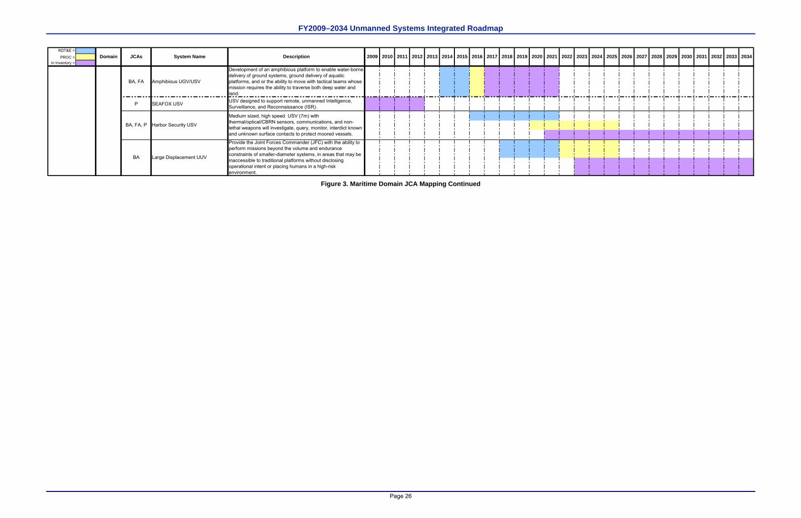
FY2009–2034 Unmanned Systems Integrated Roadmap
Page 26
RDT&E =
PROC =In Inventory =
BA, FA Amphibious UGV/USV
Development of an amphibious platform to enable water-borne delivery of ground systems, ground delivery of aquatic platforms, and or the ability to move with tactical teams whose mission requires the ability to traverse both deep water and land.
P SEAFOX USV USV designed to support remote, unmanned Intelligence, Surveillance, and Reconnaissance (ISR).
BA Large Displacement UUV
Provide the Joint Forces Commander (JFC) with the ability to perform missions beyond the volume and endurance constraints of smaller-diameter systems, in areas that may be inaccessible to traditional platforms without disclosing operational intent or placing humans in a high-risk environment.
BA, FA, P Harbor Security USV
Medium sized, high speed USV (7m) with thermal/optical/CBRN sensors, communications, and non-lethal weapons will investigate, query, monitor, interdict known and unknown surface contacts to protect moored vessels.
20212012 2013 20142010 2011 20202019 2032System NameDomain Description 203020262009 2022 2027 2028 20292024 2025JCAs 20232015 20342016 2017 2018 2031 2033
Figure 3. Maritime Domain JCA Mapping Continued
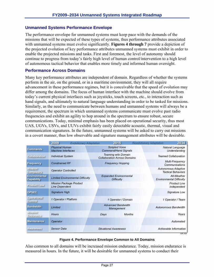
FY2009–2034 Unmanned Systems Integrated Roadmap
Page 27
Unmanned Systems Performance Envelope The performance envelope for unmanned systems must keep pace with the demands of the missions that will be expected of these types of systems, thus performance attributes associated with unmanned systems must evolve significantly. Figures 4 through 7 provide a depiction of the projected evolution of key performance attributes unmanned systems must exhibit in order to enable the projected missions and tasks. First and foremost, the level of autonomy should continue to progress from today’s fairly high level of human control/intervention to a high level of autonomous tactical behavior that enables more timely and informed human oversight.
Performance Across Domains Many key performance attributes are independent of domain. Regardless of whether the systems perform in the air, on the ground, or in a maritime environment, they will all require advancement in these performance regimes, but it is conceivable that the speed of evolution may differ among the domains. The focus of human interface with the machine should evolve from today’s current physical interfaces such as joysticks, touch screens, etc., to interaction such as hand signals, and ultimately to natural language understanding in order to be tasked for missions. Similarly, as the need to communicate between humans and unmanned systems will always be a requirement, the spectrum in which unmanned systems communicate must evolve past radio frequencies and exhibit an agility to hop around in the spectrum to ensure robust, secure communications. Today, minimal emphasis has been placed on operational security, thus most UAS, UGVs, USVs, and UUVs exhibit fairly easily detectable acoustic, thermal, visual and communication signatures. In the future, unmanned systems will be asked to carry out missions in a covert manner, thus low observable and signature management attributes will be desirable.
Figure 4. Performance Envelope Common to All Domains
Also common to all domains will be increased mission endurance. Today, mission endurance is measured in hours. In the future, it will be desirable for unmanned systems to conduct their
FY2009–2034 Unmanned Systems Integrated Roadmap
Page 28
missions in durations measured in days, weeks, months, and feasibly years. This is a key, desirable attribute as manned tasks are always constrained by the human body’s need for food and sleep. Another key desirable feature will be mission equipment packages that can be interchanged between platforms and potentially even across domains. Today, most payloads are designed for integration with a single platform. By providing interchangeability across platforms and domains, commanders will be afforded a great flexibility in terms of available options for conducting specific missions in specific types of circumstances. Finally, performance should evolve from today’s controller to platform ratio of many to one or at best one to one, to a single controller being able to monitor multiple unmanned systems performing across domains as collaborating teams.
A Discussion of Reliability, Availability, and Maintainability for Unmanned Systems While it is difficult to exactly predict the growth path for Reliability, Availability, and Maintainability (RAM) associated with unmanned systems, one thing is absolute: reliability must be achieved at a higher standard than ever before. This is due to the very nature of unmanned systems, as there will be no personnel to stop and change a flat tire for a UGV. These systems are on their own, so reliability must be at the forefront of key requirements.
It is also clear that there is a minimum threshold for reliability as the technology for these systems matures. As autonomy progresses from teleoperation, to semi-autonomy, and finally full autonomy, mission endurance will need to keep pace. The more a system is capable of doing without operator intervention, the longer it can execute on its own. The predicted performance envelope expects that as autonomy increases, so too will the call for increased mission endurance. Today, endurance is measured in hours. Twenty-five years from now, it is entirely feasible it will be measured in months. To achieve this, reliability must keep pace. Minimally, unmanned systems must be reliable enough to keep up with mission endurance times.
Given that availability is a function of reliability, maintainability, and logistics, it is also difficult to predict how this attribute will evolve over the next 25 years. Still, it is clear that the very nature of unmanned systems suggests that a greater standard will have to be met than is typical for manned systems. Unmanned systems are force multipliers precisely because they are unmanned. They enable the same number of personnel to control greater areas of responsibility and take on more mission capacity. They provide the extended stand off and reduced risk of exposure, loss of limb, and loss of life. For unmanned systems to have less than high availability is to render them a risk to the mission, as well as a burden vice a force multiplier.
Understanding the paradigm between reliability and maintainability leads to the conclusion that maintainability will require a different approach than is typical for manned systems. As autonomous behavior increases in sophistication and mission endurance increases to months, the need for self-diagnostics and self-repair becomes evident. What is less clear is how the trade space will evolve between reliability, maintainability and system duration. It is envisioned that the evolution of an unmanned system’s ability to conduct multiple missions between repairs and/or maintenance will be predicated on other performances that may be impacted. Future requirement developers will have to sort through the priorities of whether it is more important to be able to conduct multiple long endurance missions without maintenance or whether to give up such duration to preserve key performance and/or characteristics such as size, weight, speed, range, etc.
FY2009–2034 Unmanned Systems Integrated Roadmap
Page 29
Performance Specific to Domains Many performance attributes are in fact domain specific, and thus will evolve for specific types of platforms. An example is speed. Since speed is very much governed by the type of domain, the desired increase in speed will be vastly different amongst unmanned systems. In the future, UAS will likely match and/or exceed speed obtained by today’s manned aircraft. UGVs can however, easily exceed the speeds achieved by manned vehicles, particularly in rough complex terrain, precisely because they will not be constrained by the relative frailty of the human body. Similar statements can be made regarding unmanned maritime systems (UMSs) operating on and below the surface of the water. It is highly likely that unmanned surface vehicles (USVs) and unmanned undersea vehicles (UUVs), depending on mission requirements, may be required and able to achieve speeds exceeding manned vessels.
Other domain specific performance attributes include survivability, situational awareness, and maneuverability. In the air domain, maneuverability is often characterized by the ability to withstand multiples of earth’s gravitational force. The human body can only sustain 9 Gravities of Acceleration (Gs), whereas technology is the only limiting factor for unmanned systems being able to execute maneuvers that create forces reaching or exceeding 40 Gs. On the ground, gravitational force is pretty much a constant. However, the type of terrain the DoD must operate in varies widely and is often a constraint on manned vehicle maneuverability as rough terrain can put many Gs on UGVs as they bounce around, much more than a driver would be willing to tolerate for long periods of time. In the future, UGVs will be asked to maneuver in areas that manned vehicles usually do not traverse, and may even maneuver in terrains where dismounted troops are unlikely to operate. With respect to maneuver, turbulence is frequently an issue for air and maritime domain systems, but not for UGVs, except for severe storm conditions.
Situational awareness is also significantly governed by domain. In the air, UAS will need the ability to sense objects and avoid them, the biggest challenge being small objects moving at high speeds. On the ground, while speed is also a concern, UGVs have to contend with “negative obstacles.” Humans can easily discern negative obstacles such as shadows, puddles, ditches, etc., and can quickly determine if the features are navigable or if they should be avoided. Currently, on-board sensor packages and software algorithms do not easily perceive these terrain features, thus they present risk in terms of situational awareness and navigation. The ability to detect, classify, and determine the navigability of such terrain features is a key performance attribute for UGVs. On the water, UUVs and USVs have to detect, predict the path of, and avoid other moving boats (some at high speed) that are not constrained by narrow lanes. This has to be done while still observing the maritime “rules of the road.” The undersea environment adds additional complexity for UUVs to avoid low profile objects, such as fishing nets and marine mammals.
Finally, survivability will be unique for the domains. The requirement for an unmanned system to be survivable is not only dependant upon the mission it is expected to perform, but also the domain in which it operates, and tradeoffs in performance requirements. UUVs and USVs obviously must survive the very harsh salt fog, high humidity, and degradation effects of water to a far greater extent than UAS and UGVs. Also, cost will have an impact on where the survivability requirement is drawn. For more sophisticated missions, such as high altitude, long endurance UAS, or UGVs that can traverse complex terrain at high speeds, cost is relatively dear. Thus, a greater measure of survivability is desirable in order to protect the investment, but it also must be balanced against degradation in range and payload capabilities. If missions can be accomplished with low cost systems, then survivability may be completely traded away as a
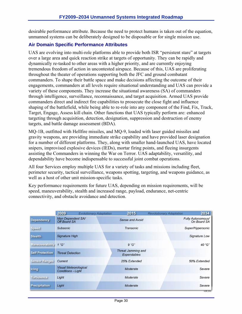
FY2009–2034 Unmanned Systems Integrated Roadmap
Page 30
desirable performance attribute. Because the need to protect humans is taken out of the equation, unmanned systems can be deliberately designed to be disposable or for single mission use.
Air Domain Specific Performance Attributes UAS are evolving into multi-role platforms able to provide both ISR “persistent stare” at targets over a large area and quick reaction strike at targets of opportunity. They can be rapidly and dynamically re-tasked to other areas with a higher priority, and are currently enjoying tremendous freedom of action in uncontested airspace. Because of this, UAS are proliferating throughout the theater of operations supporting both the JFC and ground combatant commanders. To shape their battle space and make decisions affecting the outcome of their engagements, commanders at all levels require situational understanding and UAS can provide a variety of these components. They increase the situational awareness (SA) of commanders through intelligence, surveillance, reconnaissance, and target acquisition. Armed UAS provide commanders direct and indirect fire capabilities to prosecute the close fight and influence shaping of the battlefield, while being able to re-role into any component of the Find, Fix, Track, Target, Engage, Assess kill chain. Other functions that UAS typically perform are: enhanced targeting through acquisition, detection, designation, suppression and destruction of enemy targets, and battle damage assessment (BDA).
MQ-1B, outfitted with Hellfire missiles, and MQ-9, loaded with laser guided missiles and gravity weapons, are providing immediate strike capability and have provided laser designation for a number of different platforms. They, along with smaller hand-launched UAS, have located snipers, improvised explosive devices (IEDs), mortar firing points, and fleeing insurgents assisting the Commanders in winning the War on Terror. UAS adaptability, versatility, and dependability have become indispensable to successful joint combat operations.
All four Services employ multiple UAS for a variety of tasks and missions including fleet, perimeter security, tactical surveillance, weapons spotting, targeting, and weapons guidance, as well as a host of other unit mission-specific tasks.
Key performance requirements for future UAS, depending on mission requirements, will be speed, maneuverability, stealth and increased range, payload, endurance, net-centric connectivity, and obstacle avoidance and detection.
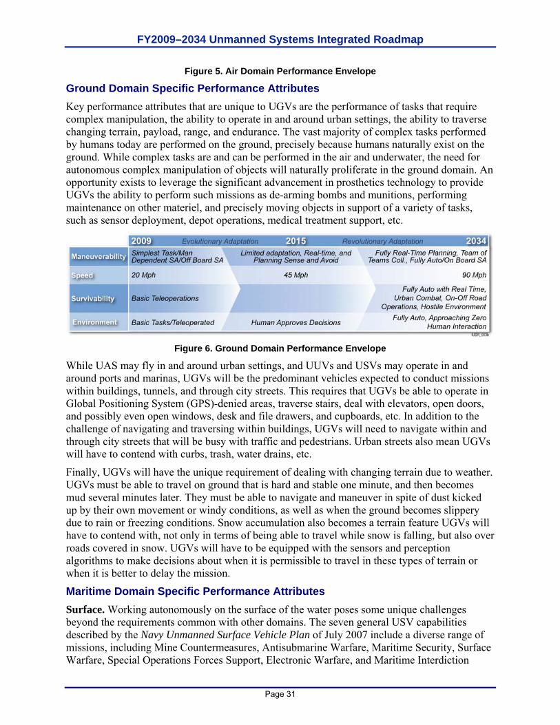
FY2009–2034 Unmanned Systems Integrated Roadmap
Page 31
Figure 5. Air Domain Performance Envelope
Ground Domain Specific Performance Attributes Key performance attributes that are unique to UGVs are the performance of tasks that require complex manipulation, the ability to operate in and around urban settings, the ability to traverse changing terrain, payload, range, and endurance. The vast majority of complex tasks performed by humans today are performed on the ground, precisely because humans naturally exist on the ground. While complex tasks are and can be performed in the air and underwater, the need for autonomous complex manipulation of objects will naturally proliferate in the ground domain. An opportunity exists to leverage the significant advancement in prosthetics technology to provide UGVs the ability to perform such missions as de-arming bombs and munitions, performing maintenance on other materiel, and precisely moving objects in support of a variety of tasks, such as sensor deployment, depot operations, medical treatment support, etc.
Figure 6. Ground Domain Performance Envelope
While UAS may fly in and around urban settings, and UUVs and USVs may operate in and around ports and marinas, UGVs will be the predominant vehicles expected to conduct missions within buildings, tunnels, and through city streets. This requires that UGVs be able to operate in Global Positioning System (GPS)-denied areas, traverse stairs, deal with elevators, open doors, and possibly even open windows, desk and file drawers, and cupboards, etc. In addition to the challenge of navigating and traversing within buildings, UGVs will need to navigate within and through city streets that will be busy with traffic and pedestrians. Urban streets also mean UGVs will have to contend with curbs, trash, water drains, etc.
Finally, UGVs will have the unique requirement of dealing with changing terrain due to weather. UGVs must be able to travel on ground that is hard and stable one minute, and then becomes mud several minutes later. They must be able to navigate and maneuver in spite of dust kicked up by their own movement or windy conditions, as well as when the ground becomes slippery due to rain or freezing conditions. Snow accumulation also becomes a terrain feature UGVs will have to contend with, not only in terms of being able to travel while snow is falling, but also over roads covered in snow. UGVs will have to be equipped with the sensors and perception algorithms to make decisions about when it is permissible to travel in these types of terrain or when it is better to delay the mission.
Maritime Domain Specific Performance Attributes Surface. Working autonomously on the surface of the water poses some unique challenges beyond the requirements common with other domains. The seven general USV capabilities described by the Navy Unmanned Surface Vehicle Plan of July 2007 include a diverse range of missions, including Mine Countermeasures, Antisubmarine Warfare, Maritime Security, Surface Warfare, Special Operations Forces Support, Electronic Warfare, and Maritime Interdiction
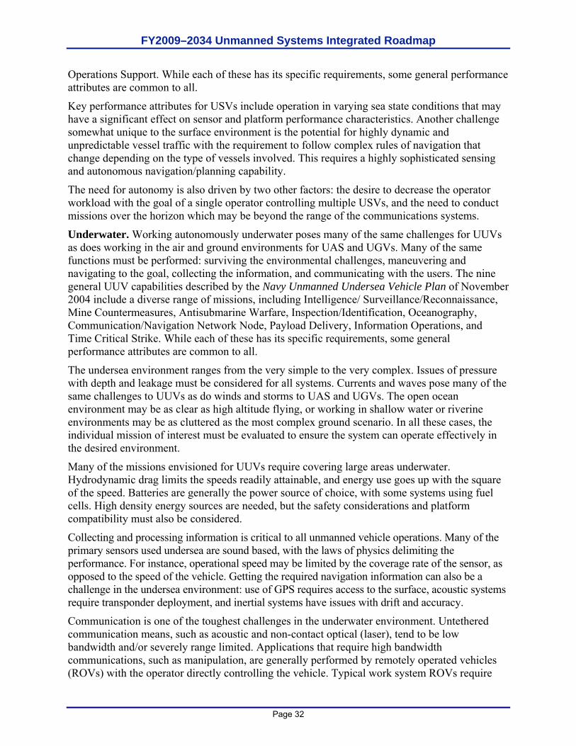
FY2009–2034 Unmanned Systems Integrated Roadmap
Page 32
Operations Support. While each of these has its specific requirements, some general performance attributes are common to all.
Key performance attributes for USVs include operation in varying sea state conditions that may have a significant effect on sensor and platform performance characteristics. Another challenge somewhat unique to the surface environment is the potential for highly dynamic and unpredictable vessel traffic with the requirement to follow complex rules of navigation that change depending on the type of vessels involved. This requires a highly sophisticated sensing and autonomous navigation/planning capability.
The need for autonomy is also driven by two other factors: the desire to decrease the operator workload with the goal of a single operator controlling multiple USVs, and the need to conduct missions over the horizon which may be beyond the range of the communications systems.
Underwater. Working autonomously underwater poses many of the same challenges for UUVs as does working in the air and ground environments for UAS and UGVs. Many of the same functions must be performed: surviving the environmental challenges, maneuvering and navigating to the goal, collecting the information, and communicating with the users. The nine general UUV capabilities described by the Navy Unmanned Undersea Vehicle Plan of November 2004 include a diverse range of missions, including Intelligence/ Surveillance/Reconnaissance, Mine Countermeasures, Antisubmarine Warfare, Inspection/Identification, Oceanography, Communication/Navigation Network Node, Payload Delivery, Information Operations, and Time Critical Strike. While each of these has its specific requirements, some general performance attributes are common to all.
The undersea environment ranges from the very simple to the very complex. Issues of pressure with depth and leakage must be considered for all systems. Currents and waves pose many of the same challenges to UUVs as do winds and storms to UAS and UGVs. The open ocean environment may be as clear as high altitude flying, or working in shallow water or riverine environments may be as cluttered as the most complex ground scenario. In all these cases, the individual mission of interest must be evaluated to ensure the system can operate effectively in the desired environment.
Many of the missions envisioned for UUVs require covering large areas underwater. Hydrodynamic drag limits the speeds readily attainable, and energy use goes up with the square of the speed. Batteries are generally the power source of choice, with some systems using fuel cells. High density energy sources are needed, but the safety considerations and platform compatibility must also be considered.
Collecting and processing information is critical to all unmanned vehicle operations. Many of the primary sensors used undersea are sound based, with the laws of physics delimiting the performance. For instance, operational speed may be limited by the coverage rate of the sensor, as opposed to the speed of the vehicle. Getting the required navigation information can also be a challenge in the undersea environment: use of GPS requires access to the surface, acoustic systems require transponder deployment, and inertial systems have issues with drift and accuracy.
Communication is one of the toughest challenges in the underwater environment. Untethered communication means, such as acoustic and non-contact optical (laser), tend to be low bandwidth and/or severely range limited. Applications that require high bandwidth communications, such as manipulation, are generally performed by remotely operated vehicles (ROVs) with the operator directly controlling the vehicle. Typical work system ROVs require
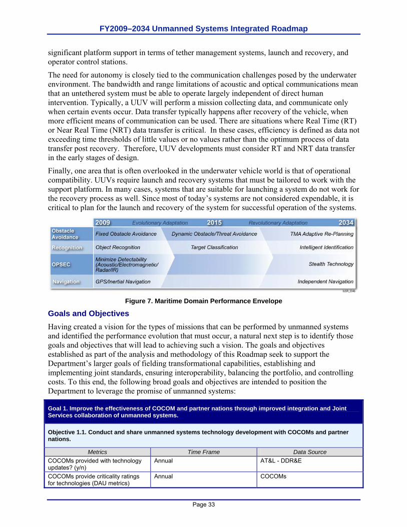
FY2009–2034 Unmanned Systems Integrated Roadmap
Page 33
significant platform support in terms of tether management systems, launch and recovery, and operator control stations.
The need for autonomy is closely tied to the communication challenges posed by the underwater environment. The bandwidth and range limitations of acoustic and optical communications mean that an untethered system must be able to operate largely independent of direct human intervention. Typically, a UUV will perform a mission collecting data, and communicate only when certain events occur. Data transfer typically happens after recovery of the vehicle, when more efficient means of communication can be used. There are situations where Real Time (RT) or Near Real Time (NRT) data transfer is critical. In these cases, efficiency is defined as data not exceeding time thresholds of little values or no values rather than the optimum process of data transfer post recovery. Therefore, UUV developments must consider RT and NRT data transfer in the early stages of design.
Finally, one area that is often overlooked in the underwater vehicle world is that of operational compatibility. UUVs require launch and recovery systems that must be tailored to work with the support platform. In many cases, systems that are suitable for launching a system do not work for the recovery process as well. Since most of today’s systems are not considered expendable, it is critical to plan for the launch and recovery of the system for successful operation of the systems.
Figure 7. Maritime Domain Performance Envelope
Goals and Objectives Having created a vision for the types of missions that can be performed by unmanned systems and identified the performance evolution that must occur, a natural next step is to identify those goals and objectives that will lead to achieving such a vision. The goals and objectives established as part of the analysis and methodology of this Roadmap seek to support the Department’s larger goals of fielding transformational capabilities, establishing and implementing joint standards, ensuring interoperability, balancing the portfolio, and controlling costs. To this end, the following broad goals and objectives are intended to position the Department to leverage the promise of unmanned systems:
Goal 1. Improve the effectiveness of COCOM and partner nations through improved integration and Joint Services collaboration of unmanned systems.
Objective 1.1. Conduct and share unmanned systems technology development with COCOMs and partner nations.
Metrics Time Frame Data Source COCOMs provided with technology updates? (y/n)
Annual AT&L - DDR&E
COCOMs provide criticality ratings for technologies (DAU metrics)
Annual COCOMs
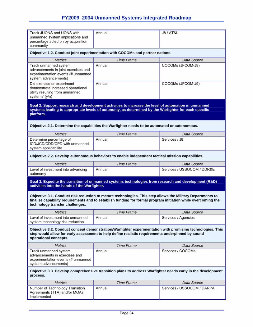
FY2009–2034 Unmanned Systems Integrated Roadmap
Page 34
Track JUONS and UONS with unmanned system implications and percentage acted on by acquisition community
Annual J8 / AT&L
Objective 1.2. Conduct joint experimentation with COCOMs and partner nations.
Metrics Time Frame Data Source Track unmanned system advancements in joint exercises and experimentation events (# unmanned system advancements)
Annual COCOMs (JFCOM-J9)
Did exercise or experiment demonstrate increased operational utility resulting from unmanned system? (y/n)
Annual COCOMs (JFCOM-J9)
Goal 2. Support research and development activities to increase the level of automation in unmanned systems leading to appropriate levels of autonomy, as determined by the Warfighter for each specific platform.
Objective 2.1. Determine the capabilities the Warfighter needs to be automated or autonomous.
Metrics Time Frame Data Source Determine percentage of ICD/JCD/CDD/CPD with unmanned system applicability
Annual Services / J8
Objective 2.2. Develop autonomous behaviors to enable independent tactical mission capabilities.
Metrics Time Frame Data Source Level of investment into advancing autonomy
Annual Services / USSOCOM / DDR&E
Goal 3. Expedite the transition of unmanned systems technologies from research and development (R&D) activities into the hands of the Warfighter.
Objective 3.1. Conduct risk reduction to mature technologies. This step allows the Military Departments to finalize capability requirements and to establish funding for formal program initiation while overcoming the technology transfer challenges.
Metrics Time Frame Data Source Level of investment into unmanned system technology risk reduction
Annual Services / Agencies
Objective 3.2. Conduct concept demonstration/Warfighter experimentation with promising technologies. This step would allow for early assessment to help define realistic requirements underpinned by sound operational concepts.
Metrics Time Frame Data Source Track unmanned system advancements in exercises and experimentation events (# unmanned system advancements)
Annual Services / COCOMs
Objective 3.3. Develop comprehensive transition plans to address Warfighter needs early in the development process.
Metrics Time Frame Data Source Number of Technology Transition Agreements (TTA) and/or MOAs implemented
Annual Services / USSOCOM / DARPA
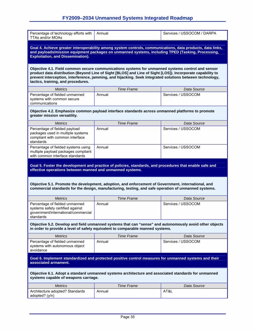
FY2009–2034 Unmanned Systems Integrated Roadmap
Page 35
Percentage of technology efforts with TTAs and/or MOAs
Annual Services / USSOCOM / DARPA
Goal 4. Achieve greater interoperability among system controls, communications, data products, data links, and payloads/mission equipment packages on unmanned systems, including TPED (Tasking, Processing, Exploitation, and Dissemination).
Objective 4.1. Field common secure communications systems for unmanned systems control and sensor product data distribution (Beyond Line of Sight [BLOS] and Line of Sight [LOS]). Incorporate capability to prevent interception, interference, jamming, and hijacking. Seek integrated solutions between technology, tactics, training, and procedures.
Metrics Time Frame Data Source Percentage of fielded unmanned systems with common secure communications
Annual Services / USSOCOM
Objective 4.2. Emphasize common payload interface standards across unmanned platforms to promote greater mission versatility.
Metrics Time Frame Data Source Percentage of fielded payload packages used in multiple systems compliant with common interface standards
Annual Services / USSOCOM
Percentage of fielded systems using multiple payload packages compliant with common interface standards
Annual Services / USSOCOM
Goal 5. Foster the development and practice of policies, standards, and procedures that enable safe and effective operations between manned and unmanned systems.
Objective 5.1. Promote the development, adoption, and enforcement of Government, international, and commercial standards for the design, manufacturing, testing, and safe operation of unmanned systems.
Metrics Time Frame Data Source Percentage of fielded unmanned systems safety certified against government/international/commercial standards
Annual Services / USSOCOM
Objective 5.2. Develop and field unmanned systems that can “sense” and autonomously avoid other objects in order to provide a level of safety equivalent to comparable manned systems.
Metrics Time Frame Data Source Percentage of fielded unmanned systems with autonomous object avoidance
Annual Services / USSOCOM
Goal 6. Implement standardized and protected positive control measures for unmanned systems and their associated armament.
Objective 6.1. Adopt a standard unmanned systems architecture and associated standards for unmanned systems capable of weapons carriage.
Metrics Time Frame Data Source Architecture adopted? Standards adopted? (y/n)
Annual AT&L
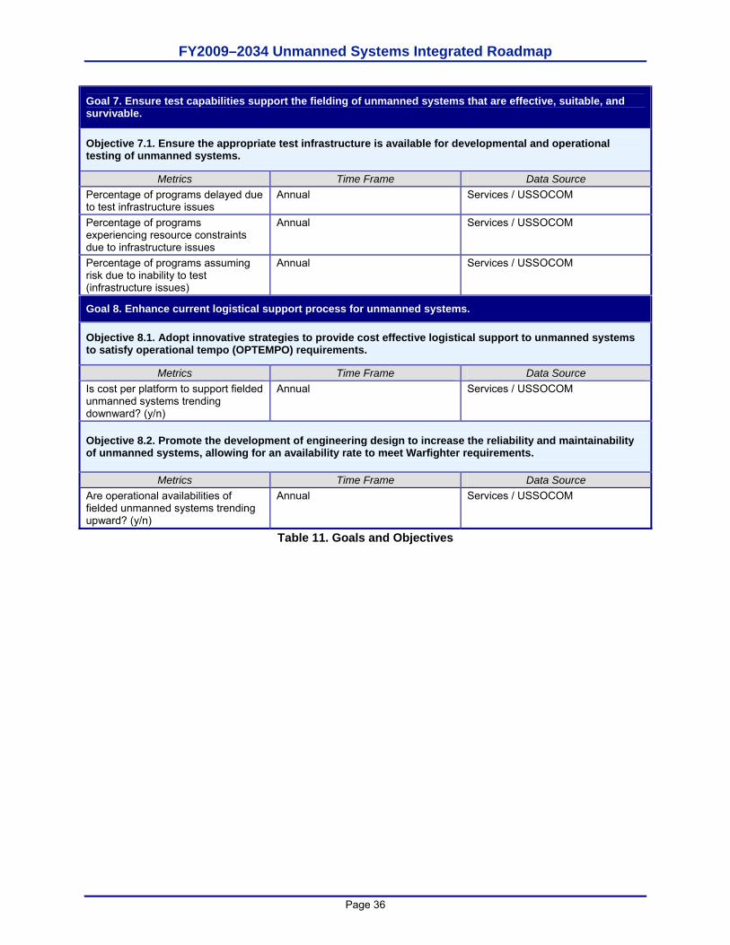
FY2009–2034 Unmanned Systems Integrated Roadmap
Page 36
Goal 7. Ensure test capabilities support the fielding of unmanned systems that are effective, suitable, and survivable.
Objective 7.1. Ensure the appropriate test infrastructure is available for developmental and operational testing of unmanned systems.
Metrics Time Frame Data Source Percentage of programs delayed due to test infrastructure issues
Annual Services / USSOCOM
Percentage of programs experiencing resource constraints due to infrastructure issues
Annual Services / USSOCOM
Percentage of programs assuming risk due to inability to test (infrastructure issues)
Annual Services / USSOCOM
Goal 8. Enhance current logistical support process for unmanned systems.
Objective 8.1. Adopt innovative strategies to provide cost effective logistical support to unmanned systems to satisfy operational tempo (OPTEMPO) requirements.
Metrics Time Frame Data Source Is cost per platform to support fielded unmanned systems trending downward? (y/n)
Annual Services / USSOCOM
Objective 8.2. Promote the development of engineering design to increase the reliability and maintainability of unmanned systems, allowing for an availability rate to meet Warfighter requirements.
Metrics Time Frame Data Source Are operational availabilities of fielded unmanned systems trending upward? (y/n)
Annual Services / USSOCOM
Table 11. Goals and Objectives
FY2009–2034 Unmanned Systems Integrated Roadmap
Page 37
CHAPTER 3. UNMANNED SYSTEMS PATH FORWARD Methodology for Analysis Having created a vision for how DoD can employ unmanned systems, the next step in establishing the Roadmap was assessing how well postured DoD is to bring about such a vision. Subject matter experts (SMEs) across the Services and Agencies in all three domains assessed DoD’s strengths, opportunities, challenges, and risks associated with unmanned systems. Items in all four categories were readily identified, indicating that while DoD can draw upon internal strengths and leverage opportunities to further the employment of unmanned systems, it still faces a multitude of challenges to address and risks that must be mitigated. Strengths and Opportunities Unmanned systems within the DoD will need to make use of their strengths and opportunities. The strengths and opportunities stem from extensive experience with unmanned systems that can be leveraged to repeat successful outcomes and avoid inefficiencies and mishaps. While experience in each domain differs widely, strengths across all domains are those things that demonstrate the ability to share lessons learned and potential technical and operational solutions that contribute to the DoD’s ability to successfully develop and employ unmanned systems with increased capability. Opportunities are those things that exist across all domains to increase the positive public attitude toward unmanned systems and to promote an increase in the unmanned systems industrial base and development of new technologies. The following highlights strengths in each of the domains: Air Domain Force Structure. UAS continue to be a vital asset to the Joint Forces Commander giving
them the ability to maintain long-term vigilance over the battlespace, but also giving them immediate strike capability if presented with an enemy high value asset (HVA). It is this combined effect that has and continues to be a force multiplier. UAS, in some missions and scenarios, can be an alternative to manned aircraft performing similar missions with lower risk to the aircrews.
Reputation. UAS continue to improve on their reputation as a reliable and invaluable partner to the Warfighter, as evidenced by the almost insatiable need for full motion video (FMV) and ISR information grows exponentially. UAS have saved countless lives, providing the Warfighter with evidence that IEDs have been planted on convoy routes, warning troops of ambushes, assisting troops in contact, and permanently removing HVAs from the battle.
RAM. While existing systems generally have a satisfactory maintenance ratio, reliability and maintenance have continued to improve as systems have matured.
Mission Complexity. As UAS continue to mature, more and more capabilities are being added to existing systems and new systems are being designed with multi-role missions in mind. This has and will continue to lead to more and more complex missions being flown.
Ground Domain IED Defeat Operations. The employment of UGVs to detect, interrogate, and defeat IEDs
has had an exponential benefit in Operation Iraqi Freedom (OIF) and Operation Enduring Freedom (OEF) by reducing risk to Warfighters. With approximately 12,000 UGV operations per year, thousands of casualties have been avoided.
FY2009–2034 Unmanned Systems Integrated Roadmap
Page 38
Supportability. UGVs have a network of repair and replacement capability enabled by the Joint Robotic Repair and Fielding (JRRF) activity both in theatre and state side. Support is provided through reservists, DA civilians, and contractor support personnel. Operational availability of UGVs is excellent.
Reputation. The evolution of ground robotics and the impact in the current wars have fostered a dependence on this important capability. UGVs have had positive exposure in the media to include governmental publications, TV, and other mainstream media.
Maritime Domain Autonomy. The unique challenges of the undersea environment have necessitated significant
R&D effort into autonomous control of UUVs. The undersea environment reduces options for external navigation sources, presents dynamic obstacles, and limits the ability to track vehicle location. Limited range of secure communication pathways to maintain acoustic security provide additional challenges to vehicle control. In order to overcome these challenges, autonomy will continue to be a major focus of UUV development.
Another strength is that a robust R&D infrastructure exists within the DoD that is inclusive of a wide variety of unmanned systems related expertise and skills. Each Service boasts a variety of laboratories that are currently pursuing technologies that will lead to the performance evolution discussed earlier in this chapter. Such expertise includes perception algorithm development, autonomous navigation, high altitude airframe expertise, maritime obstacle detection and avoidance, etc. This expertise has led to the development of technology that the federal government can license to private industry for continued development and commercial application, further extending the return on DoD’s R&D investment. As a complement to the strong R&D infrastructure, DoD encompasses an extensive test range network that enables sophisticated testing of unmanned systems in a variety of environments, ranging from extreme cold, to extreme desert heat, to jungle conditions. The following highlights opportunities in each of the domains: Industry very willing to assist DoD in shaping future vision Strong academic capability in US Universities to tap for technology development Strong, supportive Congressional interest Partnering with other Government agencies, international organizations, and countries Common interests in utilization Unmanned system R&D is significant Further economies of scale Can shape, influence, and implement standards to meet needs of unmanned community Architecture – Standardize on common operating system and message passing schema Safety Operations
Other strengths and opportunities identified for the DoD include strong Combatant Command and Service support for such systems based on their performance in theater. Because of the outstanding success of UAS and UGVs in Iraq and Afghanistan, Urgent Operational Need Statements (ONSs) have been generated that are actually requesting unmanned systems beyond the current state of the technology. While some of the urgent needs cannot be met with existing systems, the DoD has directed investments into technology development that would lead to satisfying these needs.
FY2009–2034 Unmanned Systems Integrated Roadmap
Page 39
Finally, the DoD will continue to become more experienced in the employment of unmanned systems, and operational concepts and tactics, techniques, and procedures will continue to mature. This maturation could lead to affordability becoming less of an issue, because the DoD may be able to capitalize on economies of scale through purchase of greater numbers of systems vice the minimum quantities originally purchased when such systems were first being introduced to the force structure. A better understanding of how best to employ the systems leads to a better understanding of the optimum mix of manned and unmanned systems, as well as a better understanding of the appropriate quantities per given unit structure. Challenges and Risks While opportunities for the DoD were identified as arising from its strengths, the challenges and risks faced by the DoD in pursuing greater employment of unmanned systems were viewed as distinctly different. Challenges were viewed as those impediments entirely within the DoD’s ability to overcome if it chose to address the issue. Risks were viewed as those situations outside the full control of the DoD and thus would either have to be mitigated or accepted. The challenges identified consist of the following: Lack of stable/approved requirements. The requirements process and AF doctrine for
unmanned systems has not kept pace with evolving technologies and the urgent needs of the Warfighter. Requirements creep and demands for rapid fielding have led to problems with existing and developmental unmanned platforms. It is likely that demands for rapid fielding will continue. Guidance from DoD regarding the overall UAS architecture can serve as an overall standard, mitigating future problems of UAS integration.
Insufficient emphasis on reliability and maintainability of unmanned systems. The current commitment of combat forces has seen a number of unmanned systems fielded quickly without the establishment of the required reliability and maintainability infrastructure that normally would be established prior to and during the fielding of a system. This was justifiably done as a conscious decision to save Warfighter’s lives at the risk of reliability and maintainability issues with the equipment fielded. Although the reliability and maintainability is currently at a satifactory level, there is no official requirement for reliability and maintainability. Thus, a requirement needs to be established to make sure unmanned systems have a sufficient emphasis on both.
Clash of cultures/force structure issues. Creation of substantive autonomous systems/platforms within each domain will create resourcing and leadership challenges for all the Services, while challenging their respective Warfighter cultures as well. The automating of the actual operation/fighting of platforms will decrease the need for people to crew them, while the personnel needed to simply maintain the vehicles is likely to increase. This has the potential to radically change the ‘tooth to tail’ personnel ratio in combat forces heavily in favor of the support personnel vice combatants, increasing the need for resources (people, equipment, money) for the support chain. At the same time, the need for experienced middle to senior combatant leaders and decision makers will not change, since they will know the tactics and strategies necessary to operate and direct the autonomous systems. The challenge will be developing the middle to senior combatant leaders needed in an environment allowing fewer junior combatant leaders. Culturally, there will be stresses from the potentially significant decrease in the combatant jobs of each Service, e.g. Infantry for the Army, pilots for the Air Force, etc. and the attendant reduction in numbers of the main focus of each Service, i.e. the combatants.
FY2009–2034 Unmanned Systems Integrated Roadmap
Page 40
Inefficiencies created by duplicative activities for similar functions. The rapid pace of technology change, coupled with the demands of seeking ways to use technology to save both Warfighter and noncombatant lives as soon as possible and the non-robust coordination across current activities/domains has caused some duplication of functions across the domains. This has often kept stakeholders unaware of other’s efforts, thus creating some duplication.
Coordination across current activities/domains is not robust (often stakeholders unaware of other’s efforts)/Parochialism. Coordination across current activities/domains is not institutionalized. This can and does lead to duplication of effort, and can possibly create gaps in filling the capability needs of the Warfighter.
Pockets of advocacy/no broad spectrum of acceptance/no consistent top level advocacy (at Service Headquarters level). The Combatant Commands, their components, and the individual Services have embraced unmanned systems philosophically because they are a capability multiplier and can reduce risk to personnel. However, when the procurement of unmanned systems threaten manned systems budgets or career paths of manned systems operators, the manned systems invariably win out due to vocal and forceful remonstrations by the threatened communities. Unmanned systems offer as yet largely unseen operational capabilities, and these pockets of resistance need to be addressed and eliminated, for the overall good of the Joint Force.
No defined career paths and accepted advocacy for unmanned career path. The lack of an established operational community for unmanned systems impedes the migration of careers of Warfighters assigned to unmanned operations. A defined career field with opportunities for Warfighter advancement in organizational structure is required to demonstrate the viability of a career associated with unmanned systems.
Limited formalized unmanned systems courses within Professional Military Education (PME). PME may identify unmanned systems as tools for Joint commanders to employ, but actual curriculum that explores the best employment and integration of unmanned systems into the force structure is elementary at best.
Lack of full vetting through developmental/operational test may require changes to training and retrofit of fielded systems. Unmanned systems have historically been fielded at times without going through a full vetting in developmental/operational testing. While this was done with full and good justification, weaknesses in the system appear later when actually fielded, causing the Services to have to go back and fix the issues after the fielding, incurring added costs and burdens on the acquisition and logistics systems of each Service.
Industry lacks full understanding of DoD unmanned systems needs. The acquisition process must respond more quickly to Warfighter needs and protect government interests. The inability of the JCIDS system to keep pace with the rapid rate of change of Warfighter needs for the GWOT has resulted in unmanned system requirements that are driven by what is demonstrated by vendors rather than vendors developing systems based on DoD requirements.
Integration of command and control of unmanned systems within existing and future battle command systems not well understood. The integration of the products provided to battle command systems by unmanned systems and their distribution to the Warfighter is not optimal. Planned systems with greater capability will need to have the distribution and execution architecture defined prior to development if the Department expects to realize their full potential.
FY2009–2034 Unmanned Systems Integrated Roadmap
Page 41
Operational risk with unmanned systems in the presence of environmental and/or deliberate adversarial actions. Adversary actions that would deny the use of unmanned systems by the Warfighter are of concern. These actions include but are not limited to: denial of use, sabotage/destruction of platforms, and enemy use of system against friendly forces. Environmental conditions, such as precipitation, sand storms or solar activity may degrade command, control and use of sensors on unmanned systems.
Trust of unmanned systems is still in infancy in ground and maritime domains…stronger in air domain, but still difficult to fly in U.S. airspace (trust of military as well as civilian populations). Unmanned systems are still a relatively new concept to most of the civilian population. As a result, there is a natural fear of a new and unproven technology with concerns about safety. This in turn creates difficulties for the Services to obtain approvals for proper test and evaluation of new systems, or in some cases, support for resourcing the acquisition of a new system.
Misinformed expectations for capabilities and efficiencies. Perceptions of the current capabilities of unmanned systems are often derived from information/images from other less authoritative sources, such as popular movies or books, or from over-enthusiastic vendors. This can lead the Warfighter to identify a required capability that is beyond the ability of current or projected technology to satisfy, and subsequent dissatisfaction with actual systems.
Operations. As UAS continue to proliferate across the battle space, the value they bring to the fight continues to grow and new capabilities are being explored. However, until there is a methodology that uses technology, policies, or a procedures solution, expansion into civil airspace will continue to be severely restricted. This has and will continue to have negative impacts on both aircrew training and UAS system testing until there is a resolution. There are various systems, both on and off board, and policy changes being explored to allow incremental access to the civil airspace system.
The risks identified consist of the following: Future expectations for long-duration employment of unmanned systems cannot be
supported by current energy sources. The volume and length of mission times required when combined, exceed the ability of current technology to support. This may lead to a decrease in the capabilities actually fielded, either in quantity or in length of mission capabilities.
Commercial enterprise for unmanned systems is in its infancy. As a relatively new technology, unmanned systems are undergoing rapid change. This increases the likelihood, given the vagaries of the DoD acquisition system, of a system being technologically obsolete by the time it is fielded.
Lack of stable and robust industrial base. Due to the immature nature of unmanned systems, a stable and robust industrial base that insures a dependable source of systems in volume has not yet come into existence. This has the potential of creating shortfalls in required capabilities or the lack of a source for a system following fielding.
Lack of sufficient dedicated operational frequencies for unmanned systems. The Warfighter, in embracing the positive aspects of unmanned systems, envisions deployments in numbers that may overwhelm the current capability of current RF, UHF, and VF systems to maintain communications with them. Satellite systems need to be able to control and disseminate collected data for future unmanned systems use. This may require curtailing the volume of fieldings of some systems until an alternate control method is established.
FY2009–2034 Unmanned Systems Integrated Roadmap
Page 42
Unmanned systems treaty issues − Department of Defense Directive (DoDD) 2060.1 directs that, “all DoD activities shall be
fully compliant with arms control agreements of the U.S. Government.”1 Additionally DoDD 5000.1 directs that the, “acquisition and procurement of DoD weapons and weapon systems shall be consistent with all applicable domestic law and treaties and international agreements”2 and that, “an attorney authorized to conduct such legal reviews in the Department shall conduct the legal review of the intended acquisition of weapons or weapons systems.” U.S. Government (USG) arms control agreements concerning unmanned vehicle systems (UVS) include the Wassenaar Arrangement (WA), the Missile Technology Control Regime (MTCR), the Treaty on Conventional Armed Forces in Europe (CFE), the Vienna Document 1999 (VDOC), Intermediate-Range Nuclear Forces Treaty (INF), Global Exchange of Military Information (GEMI), and the United Nations Transparency in Armaments Resolution (UNTIA). Conventional arms agreements that do not name UVS, but mention military air and ground vehicles include CFE, VDOC, INF, GEMI, and UNTIA. Conventional arms agreements that address UVS directly include WA and MTCR.
− WA controlled dual-use items include UVS in item ML 10(c) munitions list 9.A.12., and technology applicable to UVS in 9.D.1., 9.E.3., and 9.D.2. MTCR restricts UVS as a Category I item in sec. 1.A.2., provided that the UAS can carry a 500kg payload for 300km. MTCR Category II items, under section 19.A.2. and 19.A.3, include technology and equipment that may be used in Category I UVS.
− CFE Articles I and II obligate participant adherence and define conventional weapons that, within the area of application, are subject to terms of reduction and limits outlined in arts. IV-VI. UVS may, subject to review, meet the definitions of conventional armaments and equipment subject to the Treaty. Also subject to review, VDOC may require USG to report combat equipment and/or new weapons systems as they fall under art. I, paras. 10.2.5., 10.5., 11.2., and follow-on items of the VDOC. Ground launched cruise missiles (GLCM) are restricted by INF in art. II, para. 2, however, air-to-surface weapons are not considered under the INF treaty. UVS which are not ground launched, or take off without the aid of launching equipment, and are designed to return from mission, do not fall within the definition of a GLCM. GEMI requires the USG to share information on holdings of major weapons and equipment systems listed under para. 3. Air and ground vehicles, irrespective of manned or unmanned, may, upon review, fall under the categories of major weapon and equipment systems subject to information sharing under para. 3 of GEMI. Under the UNTIA Annex, Register of Conventional Arms, UVS, subject to review, may meet the definitions of items defined in 2.a., “concerning international arms transfers.”
Diminishing Federal budgets and unstable funding lines. The lack of stable funding will make industrial investment less likely and inhibit new technology development for DoD applications.
Requirements for communications systems on the future battlefield cannot be met. Commercial use of frequencies previously or currently used by military operations will increase in the future. Physics limits the available bandwidth available for all uses. New
1 DoDD 2060.1, para. 3.3.1, Jun. 9, 2001. 2 DoDD 5000.1, para E1.1.15. Legal Compliance, May 12, 2003.
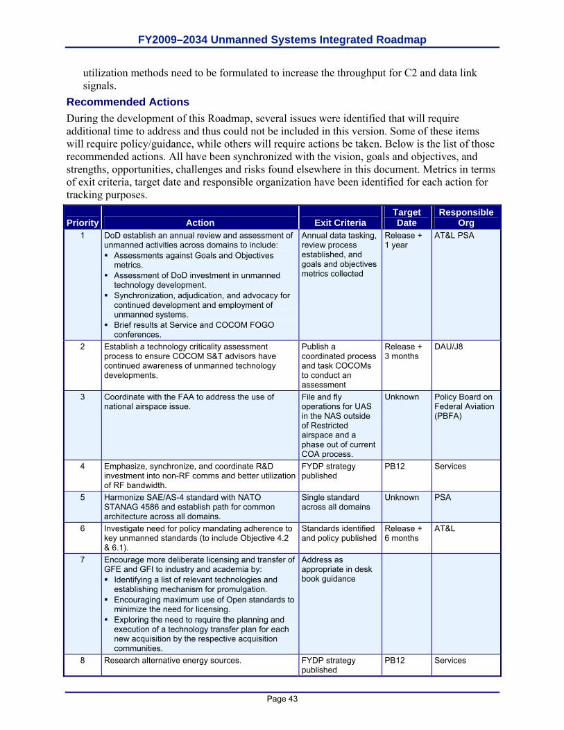
FY2009–2034 Unmanned Systems Integrated Roadmap
Page 43
utilization methods need to be formulated to increase the throughput for C2 and data link signals.
Recommended Actions During the development of this Roadmap, several issues were identified that will require additional time to address and thus could not be included in this version. Some of these items will require policy/guidance, while others will require actions be taken. Below is the list of those recommended actions. All have been synchronized with the vision, goals and objectives, and strengths, opportunities, challenges and risks found elsewhere in this document. Metrics in terms of exit criteria, target date and responsible organization have been identified for each action for tracking purposes.
Priority Action Exit Criteria Target Date
Responsible Org
1 DoD establish an annual review and assessment of unmanned activities across domains to include: Assessments against Goals and Objectives
metrics. Assessment of DoD investment in unmanned
technology development. Synchronization, adjudication, and advocacy for
continued development and employment of unmanned systems.
Brief results at Service and COCOM FOGO conferences.
Annual data tasking, review process established, and goals and objectives metrics collected
Release + 1 year
AT&L PSA
2 Establish a technology criticality assessment process to ensure COCOM S&T advisors have continued awareness of unmanned technology developments.
Publish a coordinated process and task COCOMs to conduct an assessment
Release + 3 months
DAU/J8
3 Coordinate with the FAA to address the use of national airspace issue.
File and fly operations for UAS in the NAS outside of Restricted airspace and a phase out of current COA process.
Unknown Policy Board on Federal Aviation (PBFA)
4 Emphasize, synchronize, and coordinate R&D investment into non-RF comms and better utilization of RF bandwidth.
FYDP strategy published
PB12 Services
5 Harmonize SAE/AS-4 standard with NATO STANAG 4586 and establish path for common architecture across all domains.
Single standard across all domains
Unknown PSA
6 Investigate need for policy mandating adherence to key unmanned standards (to include Objective 4.2 & 6.1).
Standards identified and policy published
Release + 6 months
AT&L
7 Encourage more deliberate licensing and transfer of GFE and GFI to industry and academia by: Identifying a list of relevant technologies and
establishing mechanism for promulgation. Encouraging maximum use of Open standards to
minimize the need for licensing. Exploring the need to require the planning and
execution of a technology transfer plan for each new acquisition by the respective acquisition communities.
Address as appropriate in desk book guidance
8 Research alternative energy sources. FYDP strategy published
PB12 Services
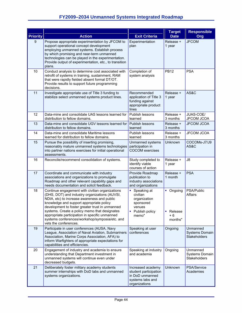
FY2009–2034 Unmanned Systems Integrated Roadmap
Page 44
Priority Action Exit Criteria Target Date
Responsible Org
9 Propose appropriate experimentation by JFCOM to support operational concept development employing unmanned systems. Establish process by which promising and near-term unmanned technologies can be played in the experimentation. Provide output of experimentation, etc., to transition plans.
Experimentation plan
Release + 1 year
JFCOM
10 Conduct analysis to determine cost associated with retrofit of systems in training, sustainment, RAM that were rapidly fielded absent formal DT/OT. Provide results to support future programming decisions.
Completion of system analysis
PB12 PSA
11 Investigate appropriate use of Title 3 funding to stabilize select unmanned systems product lines.
Recommended application of Title 3 funding against appropriate product lines
Release + 1 year
AS&C
12 Data-mine and consolidate UAS lessons learned for distribution to fellow domains.
Publish lessons learned
Release + 3 months
JUAS-COE/ JFCOM JCOA
13 Data-mine and consolidate UGV lessons learned for distribution to fellow domains.
Publish lessons learned
Release + 3 months
JFCOM JCOA
14 Data-mine and consolidate Maritime lessons learned for distribution to fellow domains.
Publish lessons learned
Release + 3 months
JFCOM JCOA
15 Pursue the possibility of inserting promising, reasonably mature unmanned systems technologies into partner nations exercises for initial operational assessments.
Unmanned systems participation in COCOM exercises
Unknown COCOMs-J7/J9 AS&C
16 Reconcile/recommend consolidation of systems. Study completed to identify viable courses of action
Release + 1 year
J8
17 Coordinate and communicate with industry associations and organizations to promulgate Roadmap and other relevant capability gaps and needs documentation and solicit feedback.
Provide Roadmap publication to industry associations and organizations
Release + 1 month
PSA
18 Continue engagement with civilian organizations (DHS, DOT) and industry organizations (AUVSI, NDIA, etc) to increase awareness and public knowledge and support appropriate policy development to foster greater trust in unmanned systems. Create a policy memo that designates appropriate participation in specific unmanned systems conferences/workshop/symposia/etc. and vets the conferences.
Speaking at civilian organization sponsored venues
Publish policy memo"
Ongoing
Release + 6 months"
PSA/Public Affairs
19 Participate in user conferences (AUSA, Navy League, Association of Naval Aviation, Submariners Association, Marine Corps Association, AFA) to inform Warfighters of appropriate expectations for capabilities and efficiencies.
Speaking at user conferences
Ongoing Unmanned Systems Domain Stakeholders
20 Engagement of industry and academia to ensure understanding that Department investment in unmanned systems will continue even under decreased budgets.
Speaking at industry and academia
Ongoing Unmanned Systems Domain Stakeholders
21 Deliberately foster military academy students summer internships with DoD labs and unmanned systems organizations.
Increased academy student participation in DoD unmanned systems labs and organizations
Unknown PSA/Service Academies
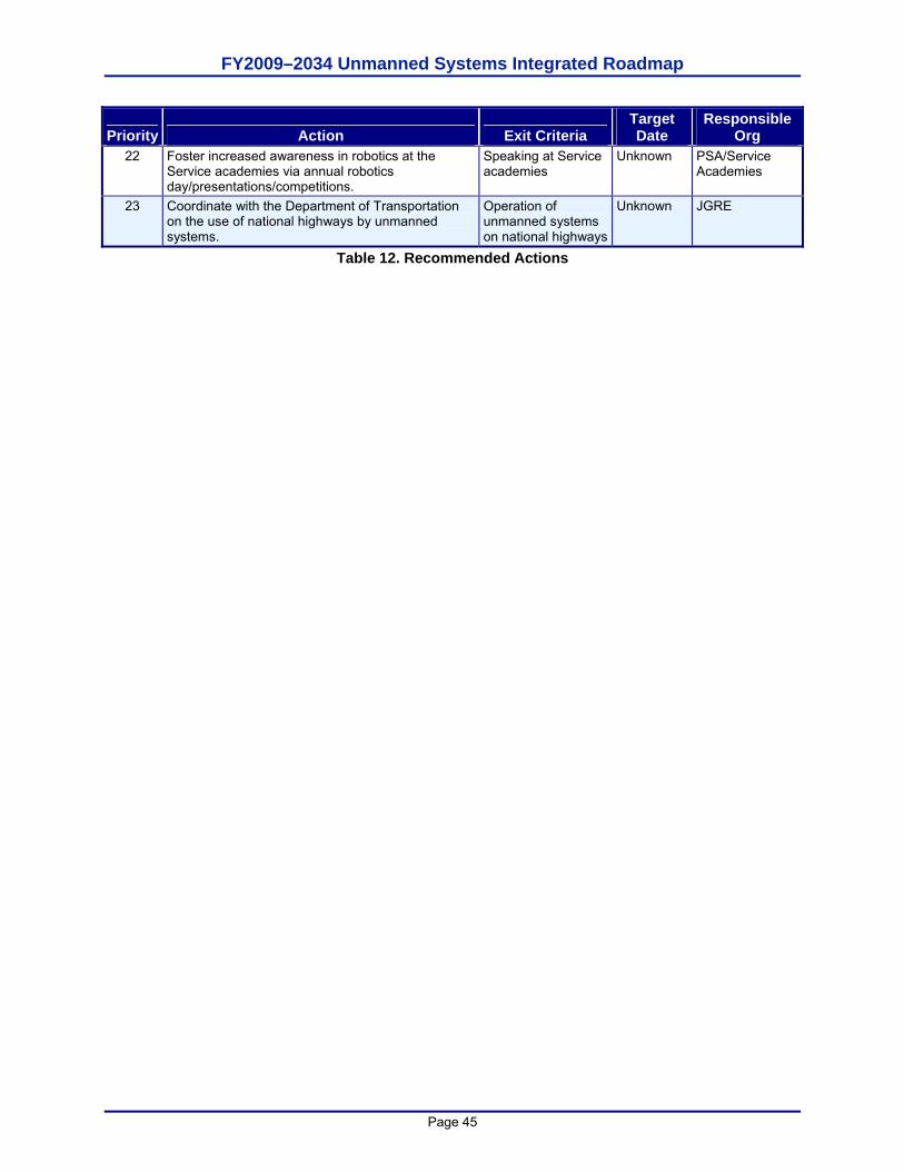
FY2009–2034 Unmanned Systems Integrated Roadmap
Page 45
Priority Action Exit Criteria Target Date
Responsible Org
22 Foster increased awareness in robotics at the Service academies via annual robotics day/presentations/competitions.
Speaking at Service academies
Unknown PSA/Service Academies
23 Coordinate with the Department of Transportation on the use of national highways by unmanned systems.
Operation of unmanned systems on national highways
Unknown JGRE
Table 12. Recommended Actions

FY2009–2034 Unmanned Systems Integrated Roadmap
Page 46
This page is intentionally left blank.
FY2009–2034 Unmanned Systems Integrated Roadmap
Page 47
CHAPTER 4. ADVANCING UNMANNED SYSTEMS TECHNOLOGIES Unmanned Systems Technology Enablers A primary objective for achieving Goal 1 in this Roadmap is the continued development of appropriate unmanned systems technology. Mapping unmanned systems to joint capability areas and projecting the needed performance envelope for those proposed systems provided the underpinning for identifying key pacing technologies that must be developed. What is identified in this Roadmap is by no means an exhaustive list, but it does provide a sense of scope of technical endeavor that will be needed to achieve the future vision for employment of unmanned systems.
The relative maturity of the technologies addressed in this Chapter run the gamut from those that will need to be started in the Tech Base via 6.1 Basic Research and 6.2 Applied Research funding, to those that simply require maturation to go from demonstration in a laboratory setting to demonstration in a more operationally relevant environment. Generally, those technologies identified in the earlier years will require less Tech Base funding, while those technologies identified at the far end of the 25 year period are almost universally in need of at least 6.2 Applied Research funding. Although everything discussed in this Chapter is a technology germane to advancing unmanned systems, what is not identified are those technologies that will be needed by unmanned systems but are also applicable across a wide range of applications. Therefore, this Roadmap does not address such technologies as lighter-weight, higher strength materials, non-corrosive materials, diagnostic sensing, etc. Each of these technologies will be desirous in an unmanned system, but they are not unique to unmanned systems and thus have not been specifically addressed in this document.
That these technologies are identified in this Roadmap does not imply that DoD must be the sole source of their development. Industry is starting to perceive robotics and autonomy as an emerging commercial market, thus the Department will be able to position itself to leverage Industry Independent Research and Development (IR&D). Cleaning is an example of where industry has already made investment into commercial applications for robotics. Thus, the DoD could likely satisfy reduced manning requirements aboard future naval vessels by leveraging commercial cleaning robots. Certain technologies that are applicable to unmanned systems can also be leveraged from other applications. Advanced prosthetics is an example of a potential source of manipulation technology. While those organizations advancing the technology of prosthetics are primarily motivated by replacing human limbs, there will likely be many opportunities to adapt that technology to satisfy requirements for highly dexterous manipulation by unmanned systems.
While this Roadmap gives an indication of when these technologies can reasonably be matured, they are projections at best. The rate at which technologies can be developed is highly dependent upon available funding and the inherent risks associated with the understanding of the basic science of the technology itself. This chapter collectively represents the technologies recommended for development by this Roadmap, but does not represent a programming plan for funding of these technologies. As with all Tech Base and Applied Technology Development funding in the Department, funding must be secured via the PPBE (Planning, Programming, Budgeting and Execution) process, taking into account all technology investments that are important to the Defense mission.
Aligning Common Technologies Figure 8 provides a summary of the identified key technologies that are applicable across each of the domains. It should be noted that while certain technologies lend themselves to application
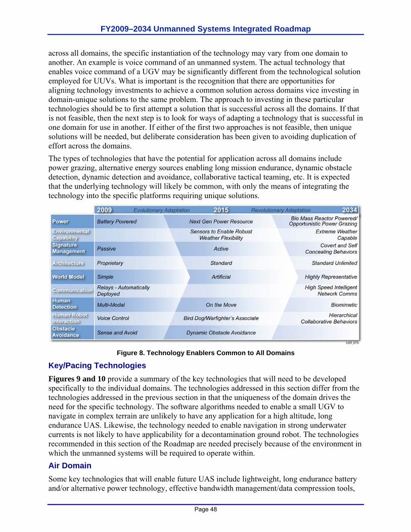
FY2009–2034 Unmanned Systems Integrated Roadmap
Page 48
across all domains, the specific instantiation of the technology may vary from one domain to another. An example is voice command of an unmanned system. The actual technology that enables voice command of a UGV may be significantly different from the technological solution employed for UUVs. What is important is the recognition that there are opportunities for aligning technology investments to achieve a common solution across domains vice investing in domain-unique solutions to the same problem. The approach to investing in these particular technologies should be to first attempt a solution that is successful across all the domains. If that is not feasible, then the next step is to look for ways of adapting a technology that is successful in one domain for use in another. If either of the first two approaches is not feasible, then unique solutions will be needed, but deliberate consideration has been given to avoiding duplication of effort across the domains. The types of technologies that have the potential for application across all domains include power grazing, alternative energy sources enabling long mission endurance, dynamic obstacle detection, dynamic detection and avoidance, collaborative tactical teaming, etc. It is expected that the underlying technology will likely be common, with only the means of integrating the technology into the specific platforms requiring unique solutions.
Figure 8. Technology Enablers Common to All Domains
Key/Pacing Technologies Figures 9 and 10 provide a summary of the key technologies that will need to be developed specifically to the individual domains. The technologies addressed in this section differ from the technologies addressed in the previous section in that the uniqueness of the domain drives the need for the specific technology. The software algorithms needed to enable a small UGV to navigate in complex terrain are unlikely to have any application for a high altitude, long endurance UAS. Likewise, the technology needed to enable navigation in strong underwater currents is not likely to have applicability for a decontamination ground robot. The technologies recommended in this section of the Roadmap are needed precisely because of the environment in which the unmanned systems will be required to operate within. Air Domain Some key technologies that will enable future UAS include lightweight, long endurance battery and/or alternative power technology, effective bandwidth management/data compression tools,
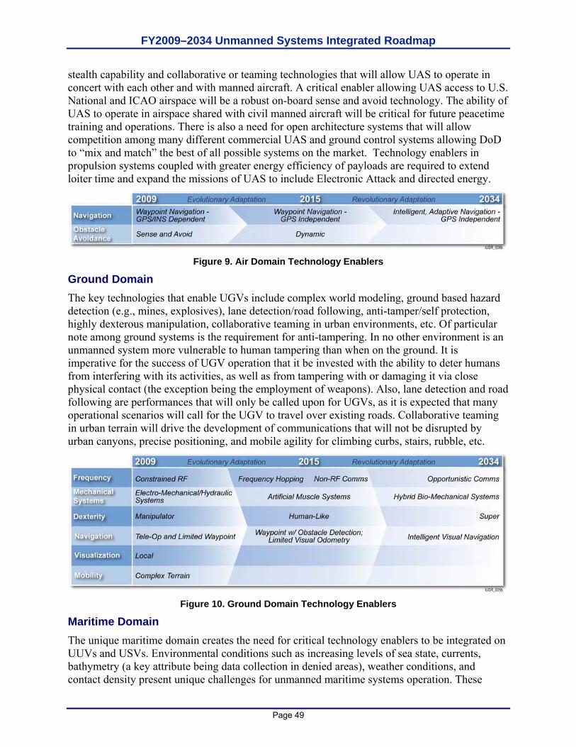
FY2009–2034 Unmanned Systems Integrated Roadmap
Page 49
stealth capability and collaborative or teaming technologies that will allow UAS to operate in concert with each other and with manned aircraft. A critical enabler allowing UAS access to U.S. National and ICAO airspace will be a robust on-board sense and avoid technology. The ability of UAS to operate in airspace shared with civil manned aircraft will be critical for future peacetime training and operations. There is also a need for open architecture systems that will allow competition among many different commercial UAS and ground control systems allowing DoD to “mix and match” the best of all possible systems on the market. Technology enablers in propulsion systems coupled with greater energy efficiency of payloads are required to extend loiter time and expand the missions of UAS to include Electronic Attack and directed energy.
Figure 9. Air Domain Technology Enablers
Ground Domain The key technologies that enable UGVs include complex world modeling, ground based hazard detection (e.g., mines, explosives), lane detection/road following, anti-tamper/self protection, highly dexterous manipulation, collaborative teaming in urban environments, etc. Of particular note among ground systems is the requirement for anti-tampering. In no other environment is an unmanned system more vulnerable to human tampering than when on the ground. It is imperative for the success of UGV operation that it be invested with the ability to deter humans from interfering with its activities, as well as from tampering with or damaging it via close physical contact (the exception being the employment of weapons). Also, lane detection and road following are performances that will only be called upon for UGVs, as it is expected that many operational scenarios will call for the UGV to travel over existing roads. Collaborative teaming in urban terrain will drive the development of communications that will not be disrupted by urban canyons, precise positioning, and mobile agility for climbing curbs, stairs, rubble, etc.
Figure 10. Ground Domain Technology Enablers
Maritime Domain The unique maritime domain creates the need for critical technology enablers to be integrated on UUVs and USVs. Environmental conditions such as increasing levels of sea state, currents, bathymetry (a key attribute being data collection in denied areas), weather conditions, and contact density present unique challenges for unmanned maritime systems operation. These

FY2009–2034 Unmanned Systems Integrated Roadmap
Page 50
conditions will require greater energy densities and more efficient and capable propulsion to support the increase in maneuverability without degrading mission endurance. Operations in high sea states will induce requirements for better stability during surface operations and more reliable communications antennas and systems. Shallow water operations will require more accurate navigational systems and improved guidance and control systems. Increased sea states and currents will require improved launch and recovery systems on the host ship or an alternative launch and recovery technique.
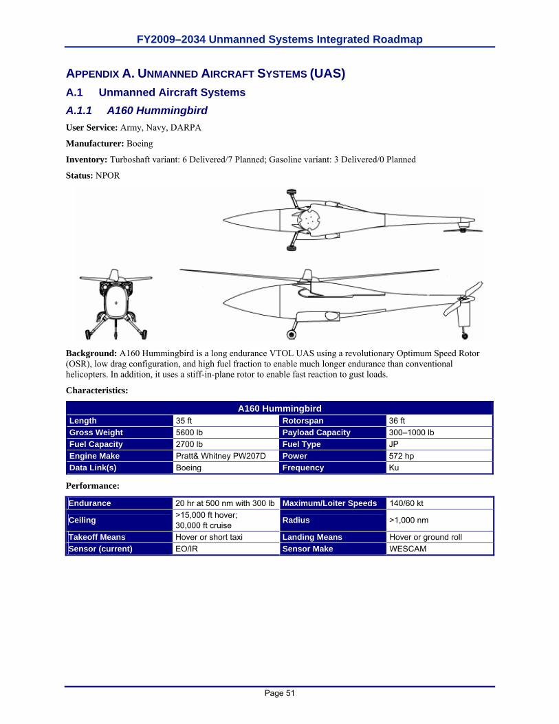
FY2009–2034 Unmanned Systems Integrated Roadmap
Page 51
APPENDIX A. UNMANNED AIRCRAFT SYSTEMS (UAS) A.1 Unmanned Aircraft Systems A.1.1 A160 Hummingbird User Service: Army, Navy, DARPA
Manufacturer: Boeing
Inventory: Turboshaft variant: 6 Delivered/7 Planned; Gasoline variant: 3 Delivered/0 Planned
Status: NPOR
Background: A160 Hummingbird is a long endurance VTOL UAS using a revolutionary Optimum Speed Rotor (OSR), low drag configuration, and high fuel fraction to enable much longer endurance than conventional helicopters. In addition, it uses a stiff-in-plane rotor to enable fast reaction to gust loads.
Characteristics:
A160 Hummingbird Length 35 ft Rotorspan 36 ft Gross Weight 5600 lb Payload Capacity 300–1000 lb Fuel Capacity 2700 lb Fuel Type JP Engine Make Pratt& Whitney PW207D Power 572 hp Data Link(s) Boeing Frequency Ku
Performance:
Endurance 20 hr at 500 nm with 300 lb Maximum/Loiter Speeds 140/60 kt
Ceiling >15,000 ft hover; 30,000 ft cruise Radius >1,000 nm
Takeoff Means Hover or short taxi Landing Means Hover or ground roll Sensor (current) EO/IR Sensor Make WESCAM
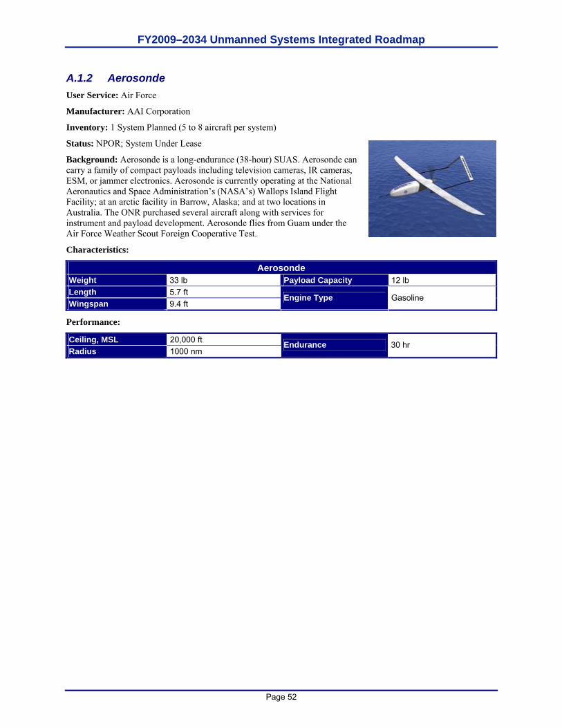
FY2009–2034 Unmanned Systems Integrated Roadmap
Page 52
A.1.2 Aerosonde User Service: Air Force
Manufacturer: AAI Corporation
Inventory: 1 System Planned (5 to 8 aircraft per system)
Status: NPOR; System Under Lease
Background: Aerosonde is a long-endurance (38-hour) SUAS. Aerosonde can carry a family of compact payloads including television cameras, IR cameras, ESM, or jammer electronics. Aerosonde is currently operating at the National Aeronautics and Space Administration’s (NASA’s) Wallops Island Flight Facility; at an arctic facility in Barrow, Alaska; and at two locations in Australia. The ONR purchased several aircraft along with services for instrument and payload development. Aerosonde flies from Guam under the Air Force Weather Scout Foreign Cooperative Test.
Characteristics:
Aerosonde Weight 33 lb Payload Capacity 12 lb Length 5.7 ft Wingspan 9.4 ft
Engine Type Gasoline
Performance:
Ceiling, MSL 20,000 ft Radius 1000 nm
Endurance 30 hr
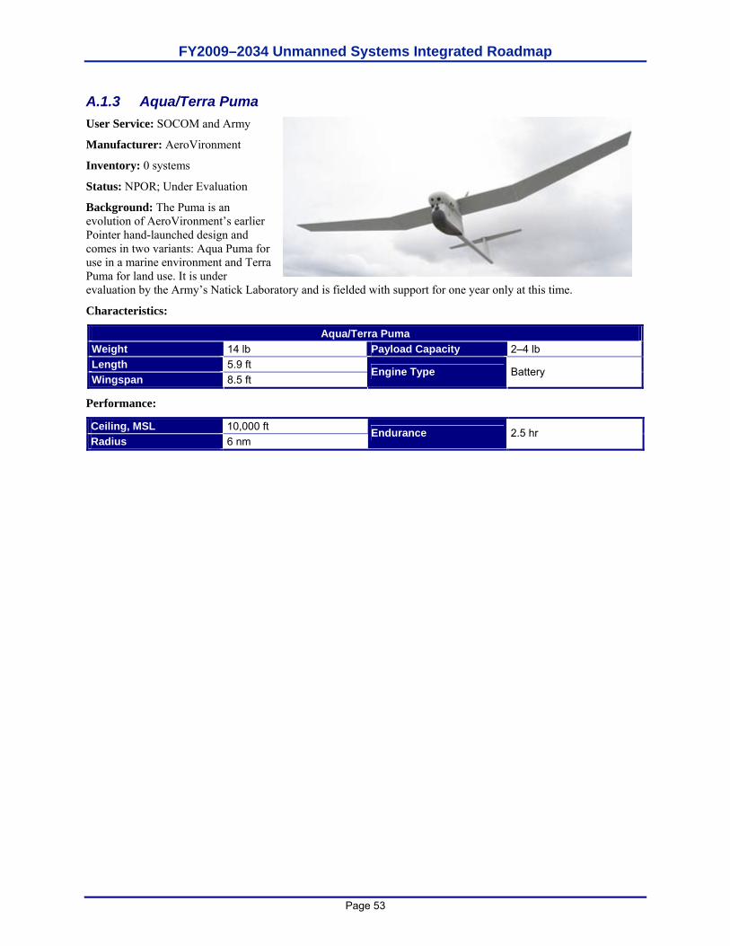
FY2009–2034 Unmanned Systems Integrated Roadmap
Page 53
A.1.3 Aqua/Terra Puma User Service: SOCOM and Army
Manufacturer: AeroVironment
Inventory: 0 systems
Status: NPOR; Under Evaluation
Background: The Puma is an evolution of AeroVironment’s earlier Pointer hand-launched design and comes in two variants: Aqua Puma for use in a marine environment and Terra Puma for land use. It is under evaluation by the Army’s Natick Laboratory and is fielded with support for one year only at this time.
Characteristics:
Aqua/Terra Puma Weight 14 lb Payload Capacity 2–4 lb Length 5.9 ft Wingspan 8.5 ft
Engine Type Battery
Performance:
Ceiling, MSL 10,000 ft Radius 6 nm
Endurance 2.5 hr
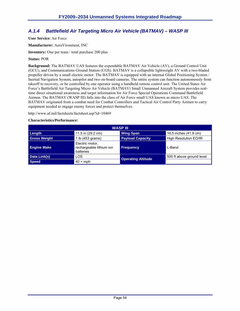
FY2009–2034 Unmanned Systems Integrated Roadmap
Page 54
A.1.4 Battlefield Air Targeting Micro Air Vehicle (BATMAV) – WASP III User Service: Air Force
Manufacturer: AeroVironment, INC
Inventory: One per team / total purchase 200 plus
Status: POR
Background: The BATMAV UAS features the expendable BATMAV Air Vehicle (AV), a Ground Control Unit (GCU), and Communications Ground Station (CGS). BATMAV is a collapsible lightweight AV with a two-bladed propeller driven by a small electric motor. The BATMAV is equipped with an internal Global Positioning System / Inertial Navigation System, autopilot and two on-board cameras. The entire system can function autonomously from takeoff to recovery, or be controlled by one operator using a handheld remote control unit. The United States Air Force’s Battlefield Air Targeting Micro Air Vehicle (BATMAV) Small Unmanned Aircraft System provides real-time direct situational awareness and target information for Air Force Special Operations Command Battlefield Airmen. The BATMAV (WASP III) falls into the class of Air Force small UAS known as micro UAS. The BATMAV originated from a combat need for Combat Controllers and Tactical Air Control Party Airmen to carry equipment needed to engage enemy forces and protect themselves.
http://www.af.mil/factsheets/factsheet.asp?id=10469
Characteristics/Performance:
WASP III Length 11.5 in (29.2 cm) Wing Span 16.5 inches (41.9 cm) Gross Weight 1 lb (453 grams) Payload Capacity High Resolution EO/IR
Engine Make Electric motor, rechargeable lithium ion batteries
Frequency L-Band
Data Link(s) LOS 500 ft above ground level Speed 40 + mph
Operating Altitude
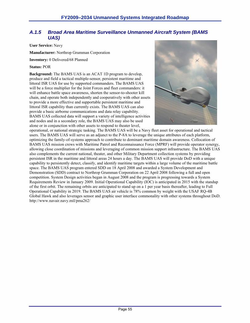
FY2009–2034 Unmanned Systems Integrated Roadmap
Page 55
A.1.5 Broad Area Maritime Surveillance Unmanned Aircraft System (BAMS UAS)
User Service: Navy
Manufacturer: Northrop Grumman Corporation
Inventory: 0 Delivered/68 Planned
Status: POR
Background: The BAMS UAS is an ACAT 1D program to develop, produce and field a tactical multiple-sensor, persistent maritime and littoral ISR UAS for use by supported commanders. The BAMS UAS will be a force multiplier for the Joint Forces and fleet commanders: it will enhance battle space awareness, shorten the sensor-to-shooter kill chain, and operate both independently and cooperatively with other assets to provide a more effective and supportable persistent maritime and littoral ISR capability than currently exists. The BAMS UAS can also provide a basic airborne communications and data relay capability. BAMS UAS collected data will support a variety of intelligence activities and nodes and in a secondary role, the BAMS UAS may also be used alone or in conjunction with other assets to respond to theater level, operational, or national strategic tasking. The BAMS UAS will be a Navy fleet asset for operational and tactical users. The BAMS UAS will serve as an adjunct to the P-8A to leverage the unique attributes of each platform, optimizing the family-of-systems approach to contribute to dominant maritime domain awareness. Collocation of BAMS UAS mission crews with Maritime Patrol and Reconnaissance Force (MPRF) will provide operator synergy, allowing close coordination of missions and leveraging of common mission support infrastructure. The BAMS UAS also complements the current national, theater, and other Military Department collection systems by providing persistent ISR in the maritime and littoral areas 24 hours a day. The BAMS UAS will provide DoD with a unique capability to persistently detect, classify, and identify maritime targets within a large volume of the maritime battle space. The BAMS UAS program entered SDD on 18 April 2008 and awarded a System Development and Demonstration (SDD) contract to Northrop Grumman Corporation on 22 April 2008 following a full and open competition. System Design activities began in August 2008 and the program is progressing towards a System Requirements Review in January 2009. Initial Operational Capability (IOC) is anticipated in 2015 with the standup of the first orbit. The remaining orbits are anticipated to stand up on a 1 per year basis thereafter, leading to Full Operational Capability in 2019. The BAMS UAS air vehicle is 78% common by weight with the USAF RQ-4B Global Hawk and also leverages sensor and graphic user interface commonality with other systems throughout DoD. http://www.navair.navy.mil/pma262/
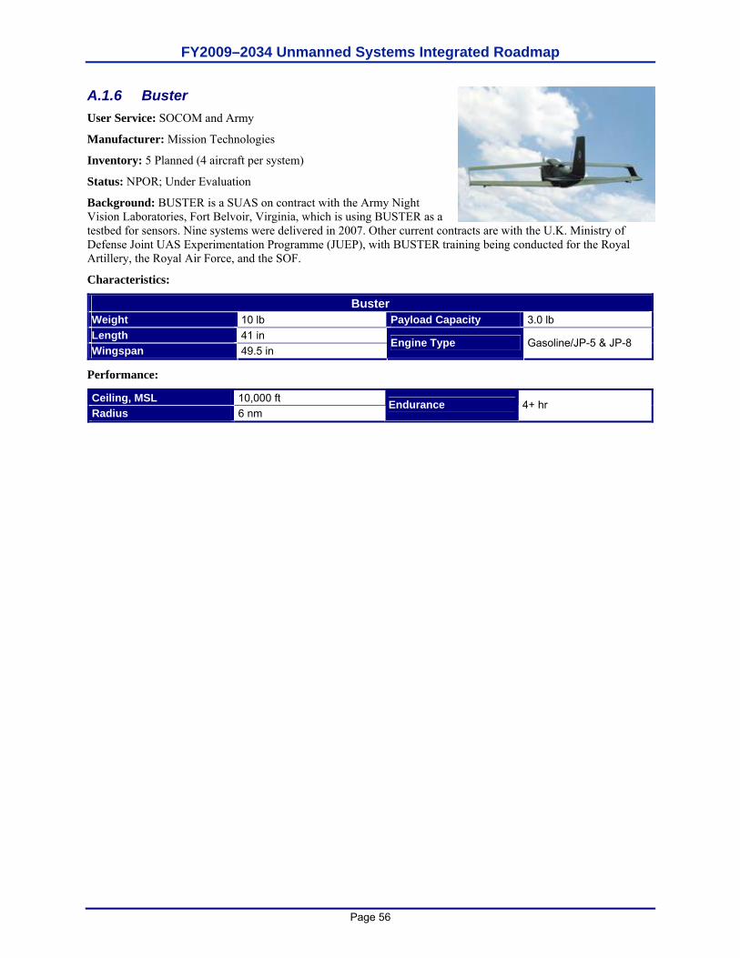
FY2009–2034 Unmanned Systems Integrated Roadmap
Page 56
A.1.6 Buster User Service: SOCOM and Army
Manufacturer: Mission Technologies
Inventory: 5 Planned (4 aircraft per system)
Status: NPOR; Under Evaluation
Background: BUSTER is a SUAS on contract with the Army Night Vision Laboratories, Fort Belvoir, Virginia, which is using BUSTER as a testbed for sensors. Nine systems were delivered in 2007. Other current contracts are with the U.K. Ministry of Defense Joint UAS Experimentation Programme (JUEP), with BUSTER training being conducted for the Royal Artillery, the Royal Air Force, and the SOF.
Characteristics:
Buster Weight 10 lb Payload Capacity 3.0 lb Length 41 in Wingspan 49.5 in
Engine Type Gasoline/JP-5 & JP-8
Performance:
Ceiling, MSL 10,000 ft Radius 6 nm
Endurance 4+ hr
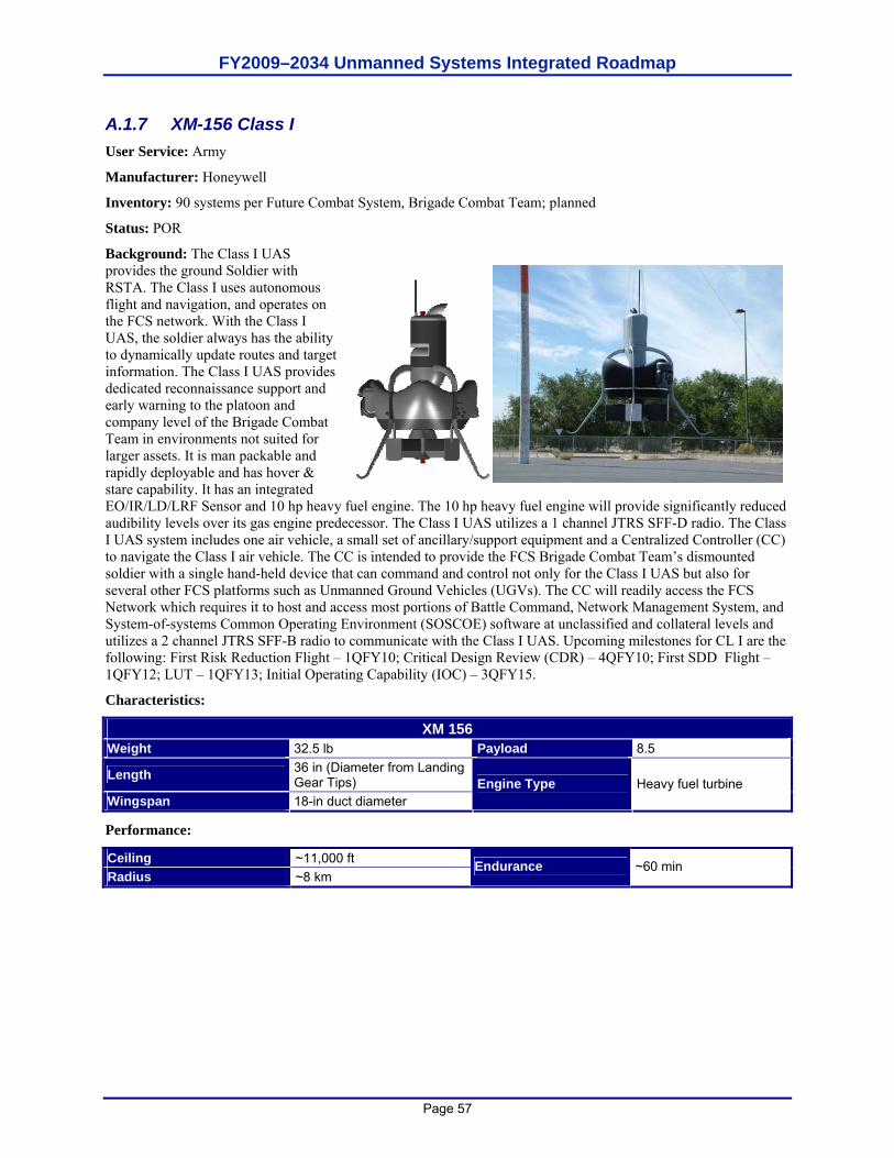
FY2009–2034 Unmanned Systems Integrated Roadmap
Page 57
A.1.7 XM-156 Class I User Service: Army
Manufacturer: Honeywell
Inventory: 90 systems per Future Combat System, Brigade Combat Team; planned
Status: POR
Background: The Class I UAS provides the ground Soldier with RSTA. The Class I uses autonomous flight and navigation, and operates on the FCS network. With the Class I UAS, the soldier always has the ability to dynamically update routes and target information. The Class I UAS provides dedicated reconnaissance support and early warning to the platoon and company level of the Brigade Combat Team in environments not suited for larger assets. It is man packable and rapidly deployable and has hover & stare capability. It has an integrated EO/IR/LD/LRF Sensor and 10 hp heavy fuel engine. The 10 hp heavy fuel engine will provide significantly reduced audibility levels over its gas engine predecessor. The Class I UAS utilizes a 1 channel JTRS SFF-D radio. The Class I UAS system includes one air vehicle, a small set of ancillary/support equipment and a Centralized Controller (CC) to navigate the Class I air vehicle. The CC is intended to provide the FCS Brigade Combat Team’s dismounted soldier with a single hand-held device that can command and control not only for the Class I UAS but also for several other FCS platforms such as Unmanned Ground Vehicles (UGVs). The CC will readily access the FCS Network which requires it to host and access most portions of Battle Command, Network Management System, and System-of-systems Common Operating Environment (SOSCOE) software at unclassified and collateral levels and utilizes a 2 channel JTRS SFF-B radio to communicate with the Class I UAS. Upcoming milestones for CL I are the following: First Risk Reduction Flight – 1QFY10; Critical Design Review (CDR) – 4QFY10; First SDD Flight – 1QFY12; LUT – 1QFY13; Initial Operating Capability (IOC) – 3QFY15.
Characteristics:
XM 156 Weight 32.5 lb Payload 8.5
Length 36 in (Diameter from Landing Gear Tips)
Wingspan 18-in duct diameter Engine Type Heavy fuel turbine
Performance:
Ceiling ~11,000 ft Radius ~8 km
Endurance ~60 min
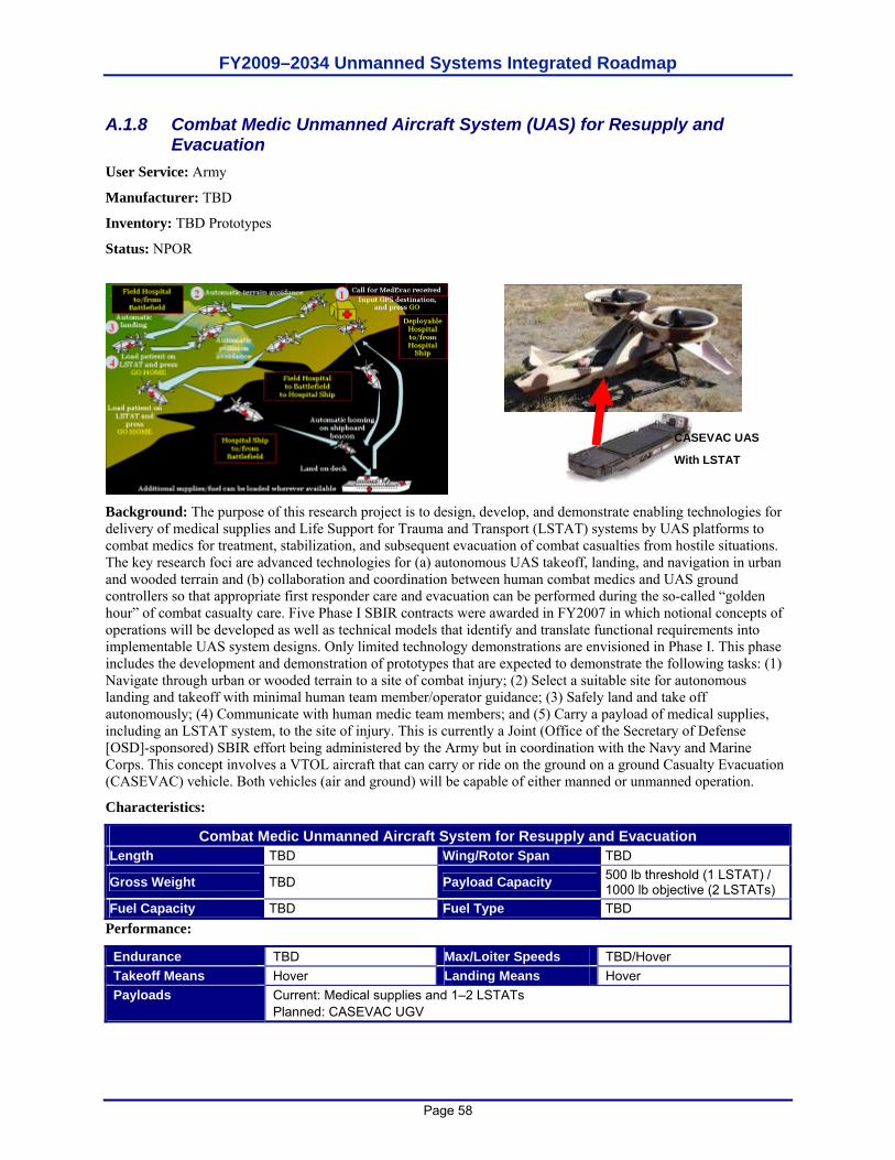
FY2009–2034 Unmanned Systems Integrated Roadmap
Page 58
A.1.8 Combat Medic Unmanned Aircraft System (UAS) for Resupply and Evacuation
User Service: Army
Manufacturer: TBD
Inventory: TBD Prototypes
Status: NPOR
Background: The purpose of this research project is to design, develop, and demonstrate enabling technologies for delivery of medical supplies and Life Support for Trauma and Transport (LSTAT) systems by UAS platforms to combat medics for treatment, stabilization, and subsequent evacuation of combat casualties from hostile situations. The key research foci are advanced technologies for (a) autonomous UAS takeoff, landing, and navigation in urban and wooded terrain and (b) collaboration and coordination between human combat medics and UAS ground controllers so that appropriate first responder care and evacuation can be performed during the so-called “golden hour” of combat casualty care. Five Phase I SBIR contracts were awarded in FY2007 in which notional concepts of operations will be developed as well as technical models that identify and translate functional requirements into implementable UAS system designs. Only limited technology demonstrations are envisioned in Phase I. This phase includes the development and demonstration of prototypes that are expected to demonstrate the following tasks: (1) Navigate through urban or wooded terrain to a site of combat injury; (2) Select a suitable site for autonomous landing and takeoff with minimal human team member/operator guidance; (3) Safely land and take off autonomously; (4) Communicate with human medic team members; and (5) Carry a payload of medical supplies, including an LSTAT system, to the site of injury. This is currently a Joint (Office of the Secretary of Defense [OSD]-sponsored) SBIR effort being administered by the Army but in coordination with the Navy and Marine Corps. This concept involves a VTOL aircraft that can carry or ride on the ground on a ground Casualty Evacuation (CASEVAC) vehicle. Both vehicles (air and ground) will be capable of either manned or unmanned operation.
Characteristics:
Combat Medic Unmanned Aircraft System for Resupply and Evacuation Length TBD Wing/Rotor Span TBD
Gross Weight TBD Payload Capacity 500 lb threshold (1 LSTAT) / 1000 lb objective (2 LSTATs)
Fuel Capacity TBD Fuel Type TBD Performance:
Endurance TBD Max/Loiter Speeds TBD/Hover Takeoff Means Hover Landing Means Hover Payloads Current: Medical supplies and 1–2 LSTATs
Planned: CASEVAC UGV
CASEVAC UAS
With LSTAT
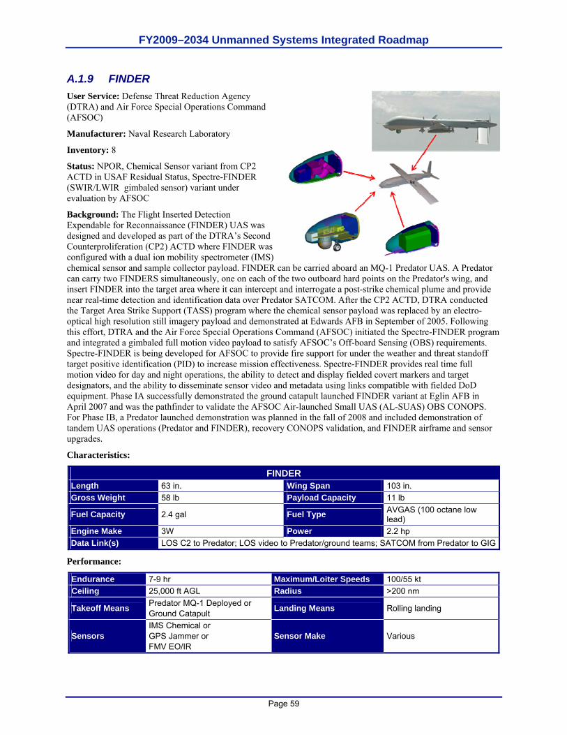
FY2009–2034 Unmanned Systems Integrated Roadmap
Page 59
A.1.9 FINDER User Service: Defense Threat Reduction Agency (DTRA) and Air Force Special Operations Command (AFSOC)
Manufacturer: Naval Research Laboratory
Inventory: 8
Status: NPOR, Chemical Sensor variant from CP2 ACTD in USAF Residual Status, Spectre-FINDER (SWIR/LWIR gimbaled sensor) variant under evaluation by AFSOC
Background: The Flight Inserted Detection Expendable for Reconnaissance (FINDER) UAS was designed and developed as part of the DTRA’s Second Counterproliferation (CP2) ACTD where FINDER was configured with a dual ion mobility spectrometer (IMS) chemical sensor and sample collector payload. FINDER can be carried aboard an MQ-1 Predator UAS. A Predator can carry two FINDERS simultaneously, one on each of the two outboard hard points on the Predator's wing, and insert FINDER into the target area where it can intercept and interrogate a post-strike chemical plume and provide near real-time detection and identification data over Predator SATCOM. After the CP2 ACTD, DTRA conducted the Target Area Strike Support (TASS) program where the chemical sensor payload was replaced by an electro-optical high resolution still imagery payload and demonstrated at Edwards AFB in September of 2005. Following this effort, DTRA and the Air Force Special Operations Command (AFSOC) initiated the Spectre-FINDER program and integrated a gimbaled full motion video payload to satisfy AFSOC’s Off-board Sensing (OBS) requirements. Spectre-FINDER is being developed for AFSOC to provide fire support for under the weather and threat standoff target positive identification (PID) to increase mission effectiveness. Spectre-FINDER provides real time full motion video for day and night operations, the ability to detect and display fielded covert markers and target designators, and the ability to disseminate sensor video and metadata using links compatible with fielded DoD equipment. Phase IA successfully demonstrated the ground catapult launched FINDER variant at Eglin AFB in April 2007 and was the pathfinder to validate the AFSOC Air-launched Small UAS (AL-SUAS) OBS CONOPS. For Phase IB, a Predator launched demonstration was planned in the fall of 2008 and included demonstration of tandem UAS operations (Predator and FINDER), recovery CONOPS validation, and FINDER airframe and sensor upgrades.
Characteristics:
FINDER Length 63 in. Wing Span 103 in. Gross Weight 58 lb Payload Capacity 11 lb
Fuel Capacity 2.4 gal Fuel Type AVGAS (100 octane low lead)
Engine Make 3W Power 2.2 hp Data Link(s) LOS C2 to Predator; LOS video to Predator/ground teams; SATCOM from Predator to GIG
Performance:
Endurance 7-9 hr Maximum/Loiter Speeds 100/55 kt Ceiling 25,000 ft AGL Radius >200 nm
Takeoff Means Predator MQ-1 Deployed or Ground Catapult Landing Means Rolling landing
Sensors IMS Chemical or GPS Jammer or FMV EO/IR
Sensor Make Various
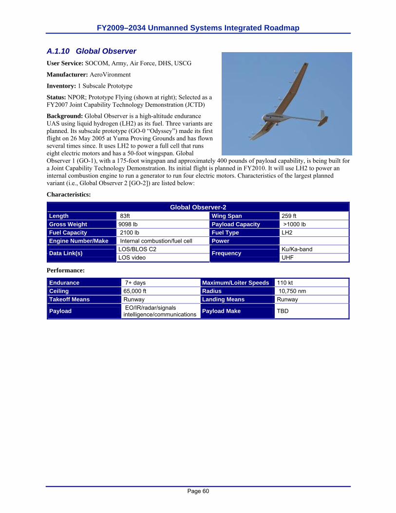
FY2009–2034 Unmanned Systems Integrated Roadmap
Page 60
A.1.10 Global Observer User Service: SOCOM, Army, Air Force, DHS, USCG
Manufacturer: AeroVironment
Inventory: 1 Subscale Prototype
Status: NPOR; Prototype Flying (shown at right); Selected as a FY2007 Joint Capability Technology Demonstration (JCTD)
Background: Global Observer is a high-altitude endurance UAS using liquid hydrogen (LH2) as its fuel. Three variants are planned. Its subscale prototype (GO-0 “Odyssey”) made its first flight on 26 May 2005 at Yuma Proving Grounds and has flown several times since. It uses LH2 to power a full cell that runs eight electric motors and has a 50-foot wingspan. Global Observer 1 (GO-1), with a 175-foot wingspan and approximately 400 pounds of payload capability, is being built for a Joint Capability Technology Demonstration. Its initial flight is planned in FY2010. It will use LH2 to power an internal combustion engine to run a generator to run four electric motors. Characteristics of the largest planned variant (i.e., Global Observer 2 [GO-2]) are listed below:
Characteristics:
Global Observer-2 Length 83ft Wing Span 259 ft Gross Weight 9098 lb Payload Capacity >1000 lb Fuel Capacity 2100 lb Fuel Type LH2 Engine Number/Make Internal combustion/fuel cell Power
LOS/BLOS C2 Ku/Ka-band Data Link(s) LOS video
Frequency UHF
Performance:
Endurance 7+ days Maximum/Loiter Speeds 110 kt Ceiling 65,000 ft Radius 10,750 nm Takeoff Means Runway Landing Means Runway
Payload EO/IR/radar/signals intelligence/communications Payload Make TBD
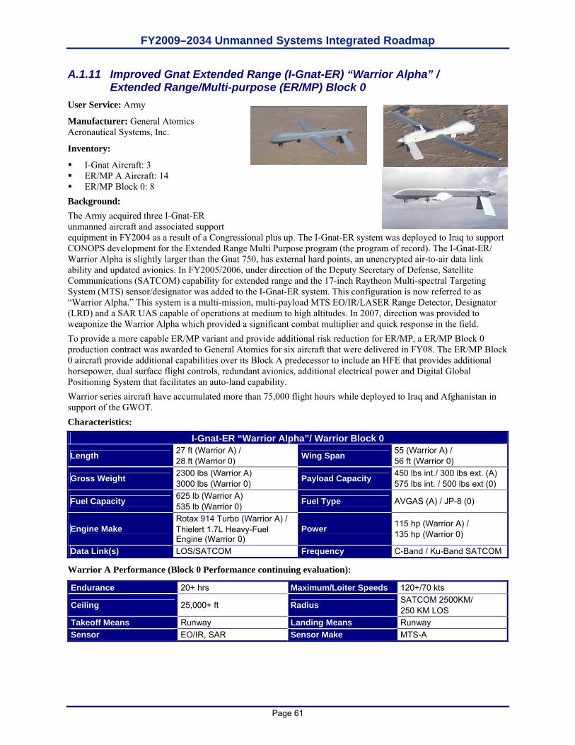
FY2009–2034 Unmanned Systems Integrated Roadmap
Page 61
A.1.11 Improved Gnat Extended Range (I-Gnat-ER) “Warrior Alpha” / Extended Range/Multi-purpose (ER/MP) Block 0
User Service: Army
Manufacturer: General Atomics Aeronautical Systems, Inc.
Inventory:
I-Gnat Aircraft: 3 ER/MP A Aircraft: 14 ER/MP Block 0: 8
Background: The Army acquired three I-Gnat-ER unmanned aircraft and associated support equipment in FY2004 as a result of a Congressional plus up. The I-Gnat-ER system was deployed to Iraq to support CONOPS development for the Extended Range Multi Purpose program (the program of record). The I-Gnat-ER/ Warrior Alpha is slightly larger than the Gnat 750, has external hard points, an unencrypted air-to-air data link ability and updated avionics. In FY2005/2006, under direction of the Deputy Secretary of Defense, Satellite Communications (SATCOM) capability for extended range and the 17-inch Raytheon Multi-spectral Targeting System (MTS) sensor/designator was added to the I-Gnat-ER system. This configuration is now referred to as “Warrior Alpha.” This system is a multi-mission, multi-payload MTS EO/IR/LASER Range Detector, Designator (LRD) and a SAR UAS capable of operations at medium to high altitudes. In 2007, direction was provided to weaponize the Warrior Alpha which provided a significant combat multiplier and quick response in the field. To provide a more capable ER/MP variant and provide additional risk reduction for ER/MP, a ER/MP Block 0 production contract was awarded to General Atomics for six aircraft that were delivered in FY08. The ER/MP Block 0 aircraft provide additional capabilities over its Block A predecessor to include an HFE that provides additional horsepower, dual surface flight controls, redundant avionics, additional electrical power and Digital Global Positioning System that facilitates an auto-land capability. Warrior series aircraft have accumulated more than 75,000 flight hours while deployed to Iraq and Afghanistan in support of the GWOT. Characteristics:
I-Gnat-ER “Warrior Alpha”/ Warrior Block 0
Length 27 ft (Warrior A) / 28 ft (Warrior 0) Wing Span 55 (Warrior A) /
56 ft (Warrior 0)
Gross Weight 2300 lbs (Warrior A) 3000 lbs (Warrior 0) Payload Capacity 450 lbs int./ 300 lbs ext. (A)
575 lbs int. / 500 lbs ext (0)
Fuel Capacity 625 lb (Warrior A) 535 lb (Warrior 0) Fuel Type AVGAS (A) / JP-8 (0)
Engine Make Rotax 914 Turbo (Warrior A) / Thielert 1.7L Heavy-Fuel Engine (Warrior 0)
Power 115 hp (Warrior A) / 135 hp (Warrior 0)
Data Link(s) LOS/SATCOM Frequency C-Band / Ku-Band SATCOM
Warrior A Performance (Block 0 Performance continuing evaluation):
Endurance 20+ hrs Maximum/Loiter Speeds 120+/70 kts
Ceiling 25,000+ ft Radius SATCOM 2500KM/ 250 KM LOS
Takeoff Means Runway Landing Means Runway Sensor EO/IR, SAR Sensor Make MTS-A
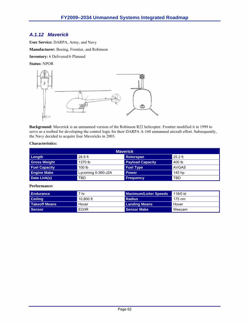
FY2009–2034 Unmanned Systems Integrated Roadmap
Page 62
A.1.12 Maverick User Service: DARPA, Army, and Navy
Manufacturer: Boeing, Frontier, and Robinson
Inventory: 6 Delivered/6 Planned
Status: NPOR
Background: Maverick is an unmanned version of the Robinson R22 helicopter. Frontier modified it in 1999 to serve as a testbed for developing the control logic for their DARPA A-160 unmanned aircraft effort. Subsequently, the Navy decided to acquire four Mavericks in 2003.
Characteristics:
Maverick Length 28.8 ft Rotorspan 25.2 ft Gross Weight 1370 lb Payload Capacity 400 lb Fuel Capacity 100 lb Fuel Type AVGAS Engine Make Lycoming 0-360-J2A Power 145 hp Data Link(s) TBD Frequency TBD
Performance:
Endurance 7 hr Maximum/Loiter Speeds 118/0 kt Ceiling 10,800 ft Radius 175 nm Takeoff Means Hover Landing Means Hover Sensor EO/IR Sensor Make Wescam

FY2009–2034 Unmanned Systems Integrated Roadmap
Page 63
A.1.13 MQ-1 Predator User Service: Air Force, Army, and Navy
Manufacturer: General Atomics Aeronautical Systems, Inc.
Inventory: 120+ (all types) Delivered/95 Available/170 Planned
Status: Program of Record (POR)
Background: The United States Air Force (USAF) MQ-1 Predator was one of the initial Advanced Concept Technology Demonstrations (ACTDs) in 1994 and transitioned to an Air Force program in 1997. Since 1995, the Predator has flown surveillance missions over Iraq, Bosnia, Kosovo, and Afghanistan. In 2001, the Air Force added a laser designator for use with precision-guided munitions and the ability to employ Hellfire missiles from the Predator; these additions led to the change in the Predator’s designation from RQ-1 to MQ-1 to reflect its multi-mission capability. The Air Force operates three Active component Predator squadrons and three Air National Guard Predator squadrons. The MQ-1 fleet reached the 170,000 flight hour mark in July 2006 with over 80 percent of the hours in combat. It was declared operationally capable (initial operational capability [IOC]) in March 2005. The Navy purchased three RQ-1As for research and development (R&D) as well as training that currently support lead-in training for the Air Force MQ-9 Reaper and Army Extended Range/Multipurpose (ER/MP) crews. http://www.af.mil/factsheets/factsheet.asp?fsID=122.
Characteristics:
MQ-1 B Length 27 ft Wing Span 55 ft Gross Weight 2250 lb Payload Capacity 450 lb Fuel Capacity 640 lb Fuel Type AVGAS Engine Make Rotax 914F Power 115 hp
BLOS Ku-band Data Link(s) LOS
Frequency C-band
Performance:
Endurance 24+ hr clean 16 hr w/external stores Maximum/Loiter Speeds 118/70 kt
Ceiling 25,000 ft Radius 500 nm Takeoff Means Runway Landing Means Runway
EO/IR Sensor(s) SAR
Weapons 2xAGM-114 Sensor Model(s) AN/AAS-52
AN/ZPQ-1
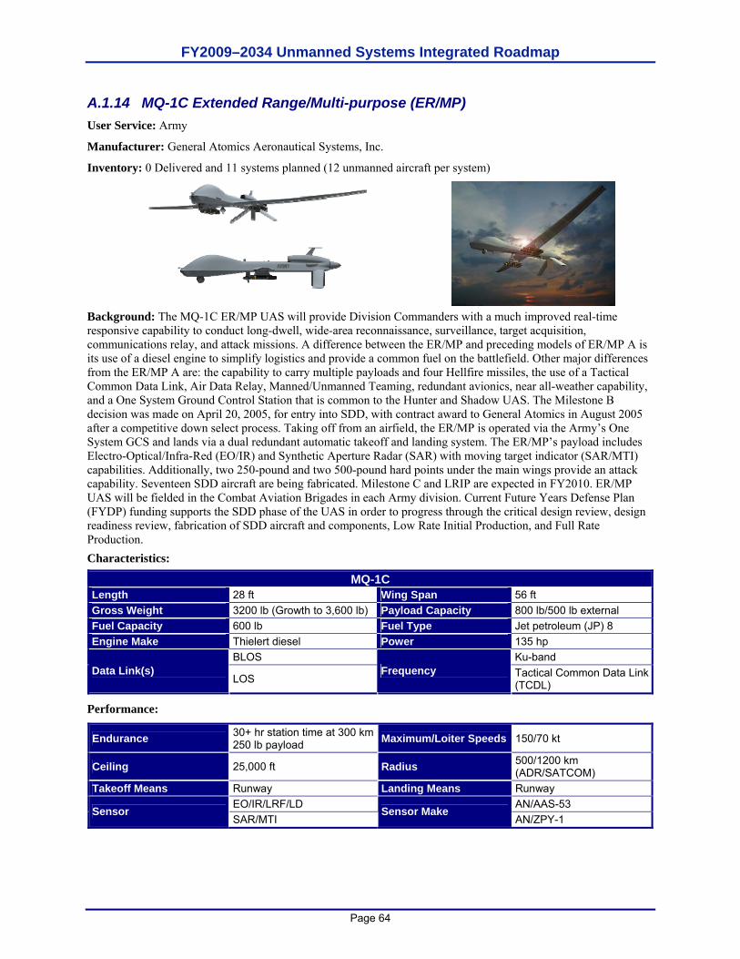
FY2009–2034 Unmanned Systems Integrated Roadmap
Page 64
A.1.14 MQ-1C Extended Range/Multi-purpose (ER/MP) User Service: Army
Manufacturer: General Atomics Aeronautical Systems, Inc.
Inventory: 0 Delivered and 11 systems planned (12 unmanned aircraft per system)
Background: The MQ-1C ER/MP UAS will provide Division Commanders with a much improved real-time responsive capability to conduct long-dwell, wide-area reconnaissance, surveillance, target acquisition, communications relay, and attack missions. A difference between the ER/MP and preceding models of ER/MP A is its use of a diesel engine to simplify logistics and provide a common fuel on the battlefield. Other major differences from the ER/MP A are: the capability to carry multiple payloads and four Hellfire missiles, the use of a Tactical Common Data Link, Air Data Relay, Manned/Unmanned Teaming, redundant avionics, near all-weather capability, and a One System Ground Control Station that is common to the Hunter and Shadow UAS. The Milestone B decision was made on April 20, 2005, for entry into SDD, with contract award to General Atomics in August 2005 after a competitive down select process. Taking off from an airfield, the ER/MP is operated via the Army’s One System GCS and lands via a dual redundant automatic takeoff and landing system. The ER/MP’s payload includes Electro-Optical/Infra-Red (EO/IR) and Synthetic Aperture Radar (SAR) with moving target indicator (SAR/MTI) capabilities. Additionally, two 250-pound and two 500-pound hard points under the main wings provide an attack capability. Seventeen SDD aircraft are being fabricated. Milestone C and LRIP are expected in FY2010. ER/MP UAS will be fielded in the Combat Aviation Brigades in each Army division. Current Future Years Defense Plan (FYDP) funding supports the SDD phase of the UAS in order to progress through the critical design review, design readiness review, fabrication of SDD aircraft and components, Low Rate Initial Production, and Full Rate Production. Characteristics:
MQ-1C Length 28 ft Wing Span 56 ft Gross Weight 3200 lb (Growth to 3,600 lb) Payload Capacity 800 lb/500 lb external Fuel Capacity 600 lb Fuel Type Jet petroleum (JP) 8 Engine Make Thielert diesel Power 135 hp
BLOS Ku-band Data Link(s)
LOS Frequency Tactical Common Data Link
(TCDL)
Performance:
Endurance 30+ hr station time at 300 km 250 lb payload Maximum/Loiter Speeds 150/70 kt
Ceiling 25,000 ft Radius 500/1200 km (ADR/SATCOM)
Takeoff Means Runway Landing Means Runway EO/IR/LRF/LD AN/AAS-53 Sensor SAR/MTI
Sensor Make AN/ZPY-1
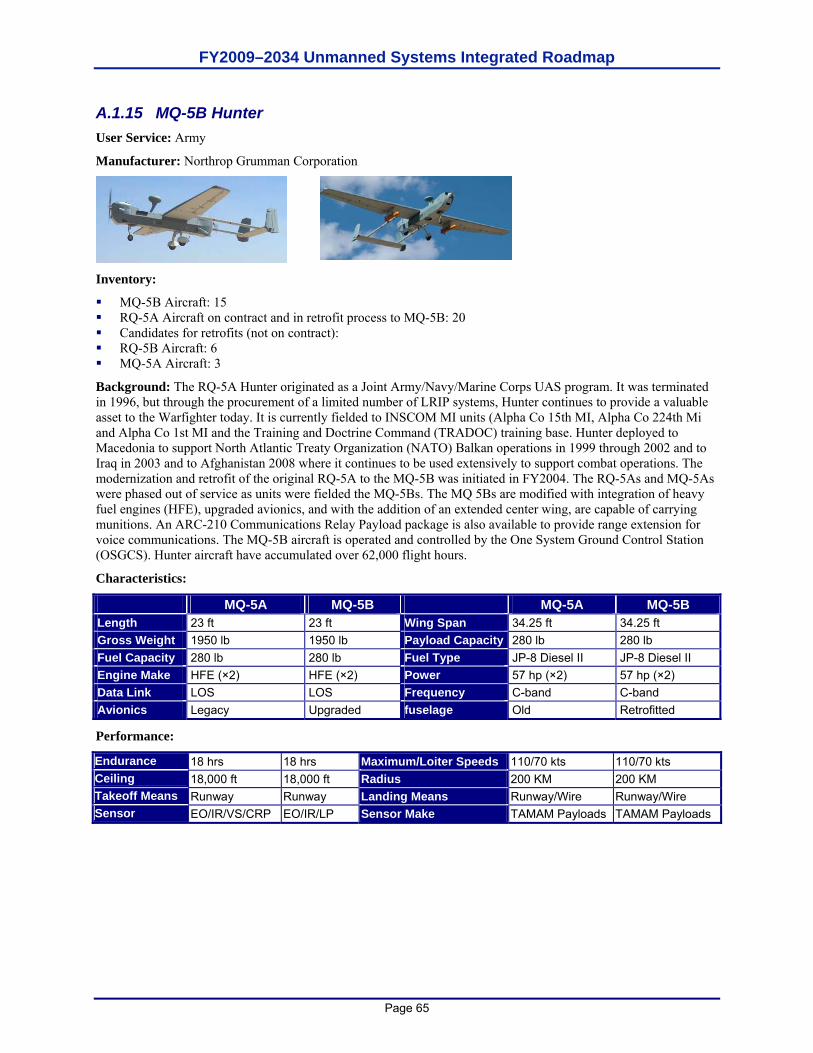
FY2009–2034 Unmanned Systems Integrated Roadmap
Page 65
A.1.15 MQ-5B Hunter User Service: Army
Manufacturer: Northrop Grumman Corporation
Inventory:
MQ-5B Aircraft: 15 RQ-5A Aircraft on contract and in retrofit process to MQ-5B: 20 Candidates for retrofits (not on contract): RQ-5B Aircraft: 6 MQ-5A Aircraft: 3
Background: The RQ-5A Hunter originated as a Joint Army/Navy/Marine Corps UAS program. It was terminated in 1996, but through the procurement of a limited number of LRIP systems, Hunter continues to provide a valuable asset to the Warfighter today. It is currently fielded to INSCOM MI units (Alpha Co 15th MI, Alpha Co 224th Mi and Alpha Co 1st MI and the Training and Doctrine Command (TRADOC) training base. Hunter deployed to Macedonia to support North Atlantic Treaty Organization (NATO) Balkan operations in 1999 through 2002 and to Iraq in 2003 and to Afghanistan 2008 where it continues to be used extensively to support combat operations. The modernization and retrofit of the original RQ-5A to the MQ-5B was initiated in FY2004. The RQ-5As and MQ-5As were phased out of service as units were fielded the MQ-5Bs. The MQ 5Bs are modified with integration of heavy fuel engines (HFE), upgraded avionics, and with the addition of an extended center wing, are capable of carrying munitions. An ARC-210 Communications Relay Payload package is also available to provide range extension for voice communications. The MQ-5B aircraft is operated and controlled by the One System Ground Control Station (OSGCS). Hunter aircraft have accumulated over 62,000 flight hours.
Characteristics:
MQ-5A MQ-5B MQ-5A MQ-5B Length 23 ft 23 ft Wing Span 34.25 ft 34.25 ft Gross Weight 1950 lb 1950 lb Payload Capacity 280 lb 280 lb Fuel Capacity 280 lb 280 lb Fuel Type JP-8 Diesel II JP-8 Diesel II Engine Make HFE (×2) HFE (×2) Power 57 hp (×2) 57 hp (×2) Data Link LOS LOS Frequency C-band C-band Avionics Legacy Upgraded fuselage Old Retrofitted
Performance:
Endurance 18 hrs 18 hrs Maximum/Loiter Speeds 110/70 kts 110/70 kts Ceiling 18,000 ft 18,000 ft Radius 200 KM 200 KM Takeoff Means Runway Runway Landing Means Runway/Wire Runway/Wire Sensor EO/IR/VS/CRP EO/IR/LP Sensor Make TAMAM Payloads TAMAM Payloads
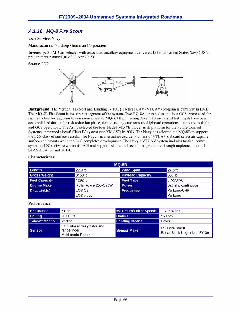
FY2009–2034 Unmanned Systems Integrated Roadmap
Page 66
A.1.16 MQ-8 Fire Scout User Service: Navy
Manufacturer: Northrop Grumman Corporation
Inventory: 3 EMD air vehicles with associated ancillary equipment delivered/131 total United States Navy (USN) procurement planned (as of 30 Apr 2008).
Status: POR
Background: The Vertical Take-off and Landing (VTOL) Tactical UAV (VTUAV) program is currently in EMD. The MQ-8B Fire Scout is the aircraft segment of the system. Two RQ-8A air vehicles and four GCSs were used for risk reduction testing prior to commencement of MQ-8B flight testing. Over 210 successful test flights have been accomplished during the risk reduction phase, demonstrating autonomous shipboard operations, autonomous flight, and GCS operations. The Army selected the four-bladed MQ-8B model as its platform for the Future Combat Systems unmanned aircraft Class IV system (see XM-157) in 2003. The Navy has selected the MQ-8B to support the LCS class of surface vessels. The Navy has also authorized deployment of VTUAV onboard select air capable surface combatants while the LCS completes development. The Navy’s VTUAV system includes tactical control system (TCS) software within its GCS and supports standards-based interoperability through implementation of STANAG 4586 and TCDL.
Characteristics:
MQ-8B Length 22.9 ft Wing Span 27.5 ft Gross Weight 3150 lb Payload Capacity 600 lb Fuel Capacity 1292 lb Fuel Type JP-5/JP-8 Engine Make Rolls Royce 250-C20W Power 320 shp continuous Data Link(s) LOS C2 Frequency Ku-band/UHF LOS video Ku-band
Performance:
Endurance 6+ hr Maximum/Loiter Speeds 117/ hover kt Ceiling 20,000 ft Radius 150 nm Takeoff Means Vertical Landing Means Hover
Sensor EO/IR/laser designator and rangefinder. Multi-mode Radar
Sensor Make FSI Brite Star II Radar Block Upgrade in FY 09
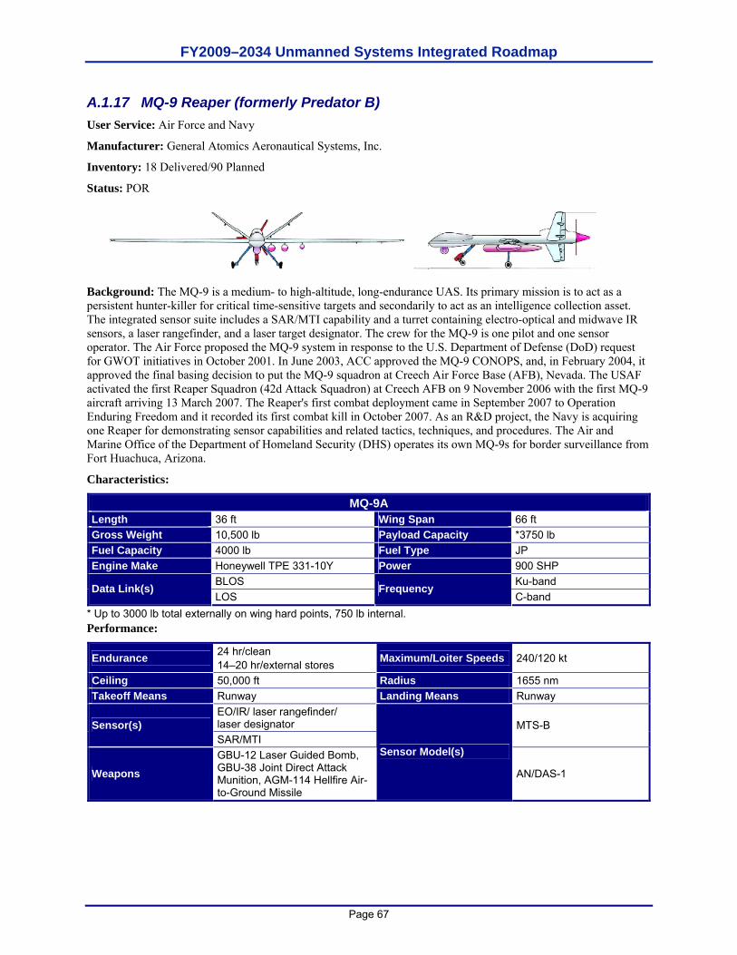
FY2009–2034 Unmanned Systems Integrated Roadmap
Page 67
A.1.17 MQ-9 Reaper (formerly Predator B) User Service: Air Force and Navy
Manufacturer: General Atomics Aeronautical Systems, Inc.
Inventory: 18 Delivered/90 Planned
Status: POR
Background: The MQ-9 is a medium- to high-altitude, long-endurance UAS. Its primary mission is to act as a persistent hunter-killer for critical time-sensitive targets and secondarily to act as an intelligence collection asset. The integrated sensor suite includes a SAR/MTI capability and a turret containing electro-optical and midwave IR sensors, a laser rangefinder, and a laser target designator. The crew for the MQ-9 is one pilot and one sensor operator. The Air Force proposed the MQ-9 system in response to the U.S. Department of Defense (DoD) request for GWOT initiatives in October 2001. In June 2003, ACC approved the MQ-9 CONOPS, and, in February 2004, it approved the final basing decision to put the MQ-9 squadron at Creech Air Force Base (AFB), Nevada. The USAF activated the first Reaper Squadron (42d Attack Squadron) at Creech AFB on 9 November 2006 with the first MQ-9 aircraft arriving 13 March 2007. The Reaper's first combat deployment came in September 2007 to Operation Enduring Freedom and it recorded its first combat kill in October 2007. As an R&D project, the Navy is acquiring one Reaper for demonstrating sensor capabilities and related tactics, techniques, and procedures. The Air and Marine Office of the Department of Homeland Security (DHS) operates its own MQ-9s for border surveillance from Fort Huachuca, Arizona.
Characteristics:
MQ-9A Length 36 ft Wing Span 66 ft Gross Weight 10,500 lb Payload Capacity *3750 lb Fuel Capacity 4000 lb Fuel Type JP Engine Make Honeywell TPE 331-10Y Power 900 SHP
BLOS Ku-band Data Link(s) LOS
Frequency C-band
* Up to 3000 lb total externally on wing hard points, 750 lb internal. Performance:
Endurance 24 hr/clean 14–20 hr/external stores Maximum/Loiter Speeds 240/120 kt
Ceiling 50,000 ft Radius 1655 nm Takeoff Means Runway Landing Means Runway
EO/IR/ laser rangefinder/ laser designator Sensor(s) SAR/MTI
MTS-B
Weapons GBU-12 Laser Guided Bomb, GBU-38 Joint Direct Attack Munition, AGM-114 Hellfire Air-to-Ground Missile
Sensor Model(s)
AN/DAS-1
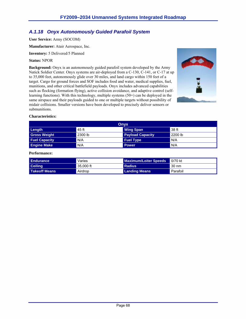
FY2009–2034 Unmanned Systems Integrated Roadmap
Page 68
A.1.18 Onyx Autonomously Guided Parafoil System User Service: Army (SOCOM)
Manufacturer: Atair Aerospace, Inc.
Inventory: 5 Delivered/5 Planned
Status: NPOR
Background: Onyx is an autonomously guided parafoil system developed by the Army Natick Soldier Center. Onyx systems are air-deployed from a C-130, C-141, or C-17 at up to 35,000 feet, autonomously glide over 30 miles, and land cargo within 150 feet of a target. Cargo for ground forces and SOF includes food and water, medical supplies, fuel, munitions, and other critical battlefield payloads. Onyx includes advanced capabilities such as flocking (formation flying), active collision avoidance, and adaptive control (self-learning functions). With this technology, multiple systems (50+) can be deployed in the same airspace and their payloads guided to one or multiple targets without possibility of midair collisions. Smaller versions have been developed to precisely deliver sensors or submunitions.
Characteristics:
Onyx Length 45 ft Wing Span 38 ft Gross Weight 2300 lb Payload Capacity 2200 lb Fuel Capacity N/A Fuel Type N/A Engine Make N/A Power N/A
Performance:
Endurance Varies Maximum/Loiter Speeds 0/70 kt Ceiling 35,000 ft Radius 30 nm Takeoff Means Airdrop Landing Means Parafoil
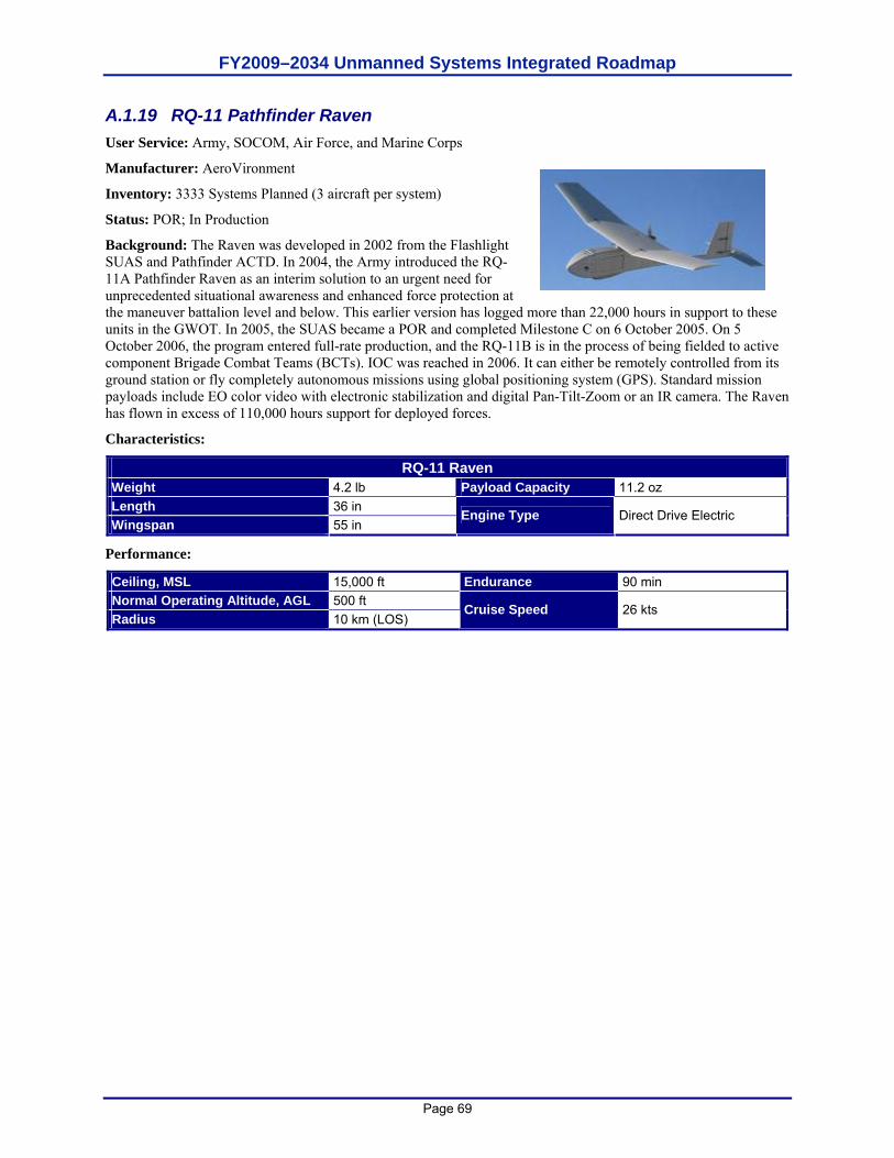
FY2009–2034 Unmanned Systems Integrated Roadmap
Page 69
A.1.19 RQ-11 Pathfinder Raven User Service: Army, SOCOM, Air Force, and Marine Corps
Manufacturer: AeroVironment
Inventory: 3333 Systems Planned (3 aircraft per system)
Status: POR; In Production
Background: The Raven was developed in 2002 from the Flashlight SUAS and Pathfinder ACTD. In 2004, the Army introduced the RQ-11A Pathfinder Raven as an interim solution to an urgent need for unprecedented situational awareness and enhanced force protection at the maneuver battalion level and below. This earlier version has logged more than 22,000 hours in support to these units in the GWOT. In 2005, the SUAS became a POR and completed Milestone C on 6 October 2005. On 5 October 2006, the program entered full-rate production, and the RQ-11B is in the process of being fielded to active component Brigade Combat Teams (BCTs). IOC was reached in 2006. It can either be remotely controlled from its ground station or fly completely autonomous missions using global positioning system (GPS). Standard mission payloads include EO color video with electronic stabilization and digital Pan-Tilt-Zoom or an IR camera. The Raven has flown in excess of 110,000 hours support for deployed forces.
Characteristics:
RQ-11 Raven Weight 4.2 lb Payload Capacity 11.2 oz Length 36 in Wingspan 55 in
Engine Type Direct Drive Electric
Performance:
Ceiling, MSL 15,000 ft Endurance 90 min Normal Operating Altitude, AGL 500 ft Radius 10 km (LOS)
Cruise Speed 26 kts
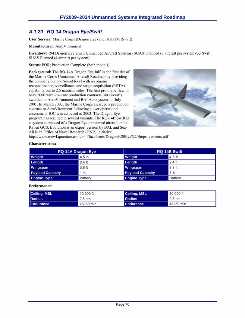
FY2009–2034 Unmanned Systems Integrated Roadmap
Page 70
A.1.20 RQ-14 Dragon Eye/Swift User Service: Marine Corps (Dragon Eye) and SOCOM (Swift)
Manufacturer: AeroVironment
Inventory: 194 Dragon Eye Small Unmanned Aircraft Systems (SUAS) Planned (3 aircraft per system)/33 Swift SUAS Planned (4 aircraft per system)
Status: POR; Production Complete (both models)
Background: The RQ-14A Dragon Eye fulfills the first tier of the Marine Corps Unmanned Aircraft Roadmap by providing the company/platoon/squad level with an organic reconnaissance, surveillance, and target acquisition (RSTA) capability out to 2.5 nautical miles. The first prototype flew in May 2000 with low-rate production contracts (40 aircraft) awarded to AeroVironment and BAI Aerosystems in July 2001. In March 2003, the Marine Corps awarded a production contract to AeroVironment following a user operational assessment. IOC was achieved in 2003. The Dragon Eye program has resulted in several variants. The RQ-14B Swift is a system composed of a Dragon Eye unmanned aircraft and a Raven GCS, Evolution is an export version by BAI, and Sea-All is an Office of Naval Research (ONR) initiative. http://www.mcwl.quantico.usmc.mil/factsheets/Dragon%20Eye%20Improvements.pdf
Characteristics:
RQ-14A Dragon Eye RQ-14B Swift Weight 4.5 lb Weight 4.5 lb Length 2.4 ft Length 2.4 ft Wingspan 3.8 ft Wingspan 3.8 ft Payload Capacity 1 lb Payload Capacity 1 lb Engine Type Battery Engine Type Battery
Performance:
Ceiling, MSL 10,000 ft Ceiling, MSL 10,000 ft Radius 2.5 nm Radius 2.5 nm Endurance 45–60 min Endurance 45–60 min
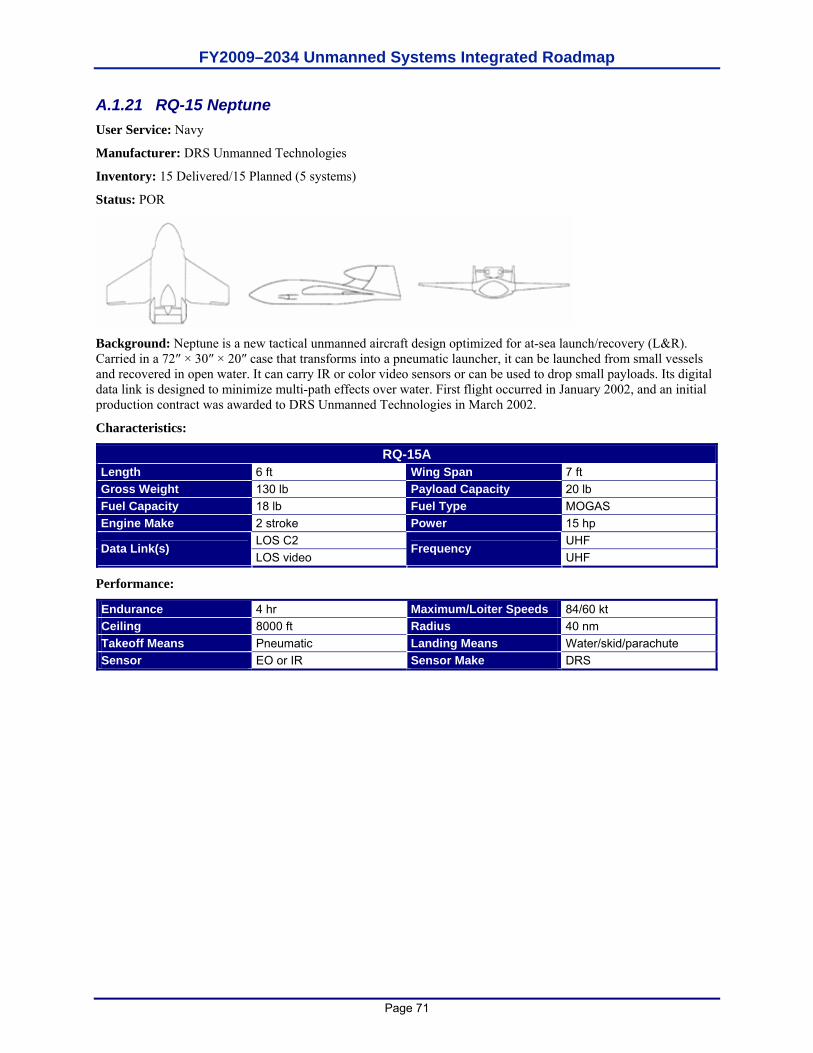
FY2009–2034 Unmanned Systems Integrated Roadmap
Page 71
A.1.21 RQ-15 Neptune User Service: Navy
Manufacturer: DRS Unmanned Technologies
Inventory: 15 Delivered/15 Planned (5 systems)
Status: POR
Background: Neptune is a new tactical unmanned aircraft design optimized for at-sea launch/recovery (L&R). Carried in a 72″ × 30″ × 20″ case that transforms into a pneumatic launcher, it can be launched from small vessels and recovered in open water. It can carry IR or color video sensors or can be used to drop small payloads. Its digital data link is designed to minimize multi-path effects over water. First flight occurred in January 2002, and an initial production contract was awarded to DRS Unmanned Technologies in March 2002.
Characteristics:
RQ-15A Length 6 ft Wing Span 7 ft Gross Weight 130 lb Payload Capacity 20 lb Fuel Capacity 18 lb Fuel Type MOGAS Engine Make 2 stroke Power 15 hp
LOS C2 UHF Data Link(s) LOS video
Frequency UHF
Performance:
Endurance 4 hr Maximum/Loiter Speeds 84/60 kt Ceiling 8000 ft Radius 40 nm Takeoff Means Pneumatic Landing Means Water/skid/parachute Sensor EO or IR Sensor Make DRS
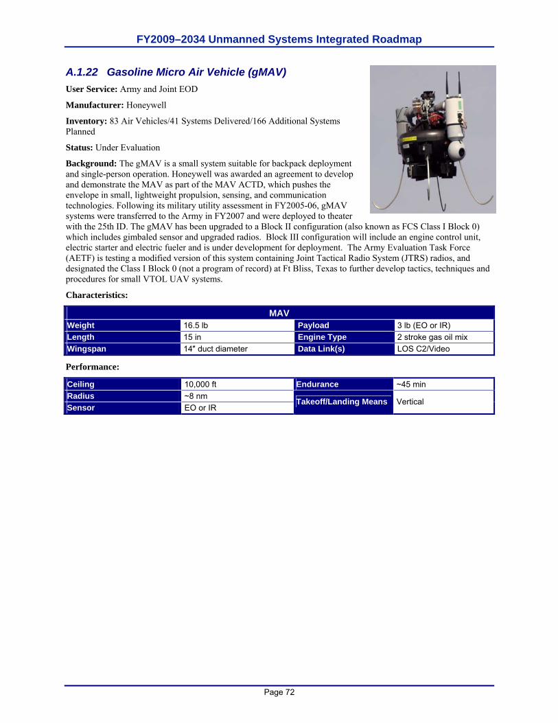
FY2009–2034 Unmanned Systems Integrated Roadmap
Page 72
A.1.22 Gasoline Micro Air Vehicle (gMAV) User Service: Army and Joint EOD
Manufacturer: Honeywell
Inventory: 83 Air Vehicles/41 Systems Delivered/166 Additional Systems Planned
Status: Under Evaluation
Background: The gMAV is a small system suitable for backpack deployment and single-person operation. Honeywell was awarded an agreement to develop and demonstrate the MAV as part of the MAV ACTD, which pushes the envelope in small, lightweight propulsion, sensing, and communication technologies. Following its military utility assessment in FY2005-06, gMAV systems were transferred to the Army in FY2007 and were deployed to theater with the 25th ID. The gMAV has been upgraded to a Block II configuration (also known as FCS Class I Block 0) which includes gimbaled sensor and upgraded radios. Block III configuration will include an engine control unit, electric starter and electric fueler and is under development for deployment. The Army Evaluation Task Force (AETF) is testing a modified version of this system containing Joint Tactical Radio System (JTRS) radios, and designated the Class I Block 0 (not a program of record) at Ft Bliss, Texas to further develop tactics, techniques and procedures for small VTOL UAV systems.
Characteristics:
MAV Weight 16.5 lb Payload 3 lb (EO or IR) Length 15 in Engine Type 2 stroke gas oil mix Wingspan 14″ duct diameter Data Link(s) LOS C2/Video
Performance:
Ceiling 10,000 ft Endurance ~45 min Radius ~8 nm Sensor EO or IR
Takeoff/Landing Means Vertical
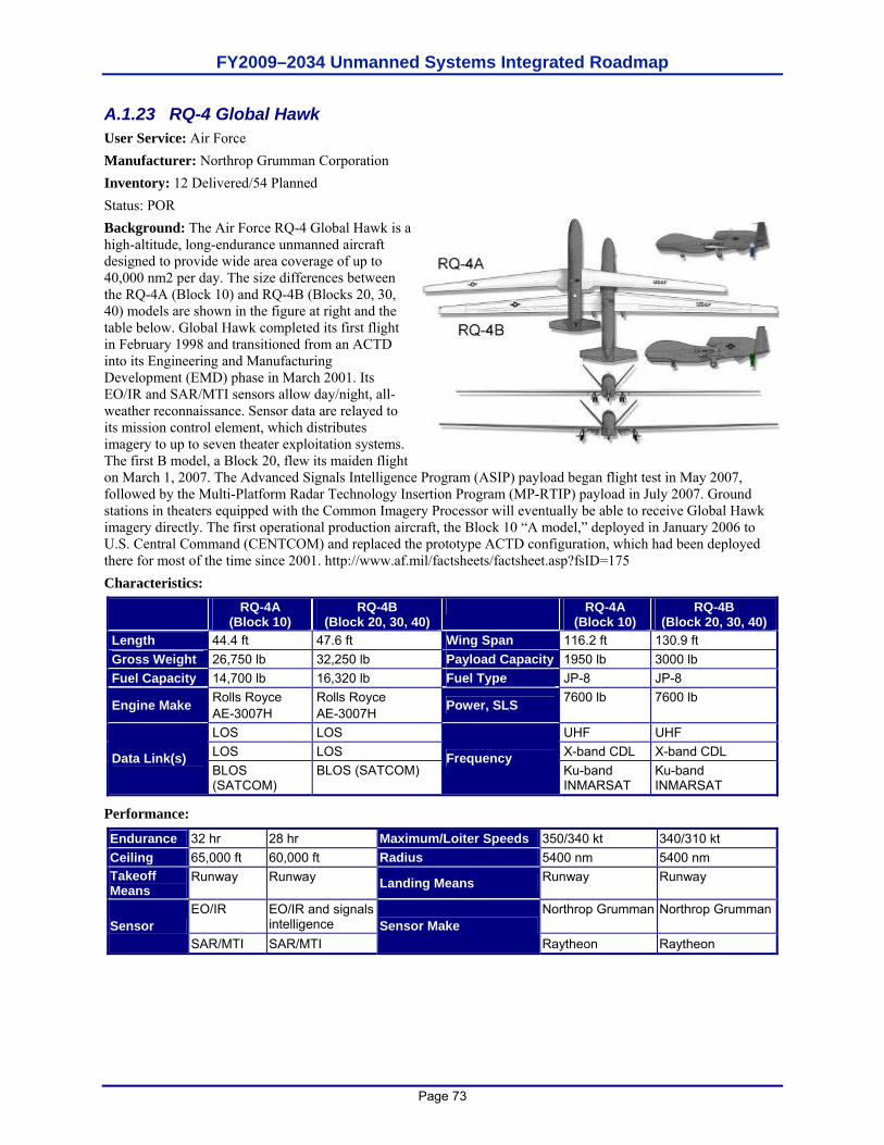
FY2009–2034 Unmanned Systems Integrated Roadmap
Page 73
A.1.23 RQ-4 Global Hawk User Service: Air Force Manufacturer: Northrop Grumman Corporation Inventory: 12 Delivered/54 Planned Status: POR Background: The Air Force RQ-4 Global Hawk is a high-altitude, long-endurance unmanned aircraft designed to provide wide area coverage of up to 40,000 nm2 per day. The size differences between the RQ-4A (Block 10) and RQ-4B (Blocks 20, 30, 40) models are shown in the figure at right and the table below. Global Hawk completed its first flight in February 1998 and transitioned from an ACTD into its Engineering and Manufacturing Development (EMD) phase in March 2001. Its EO/IR and SAR/MTI sensors allow day/night, all-weather reconnaissance. Sensor data are relayed to its mission control element, which distributes imagery to up to seven theater exploitation systems. The first B model, a Block 20, flew its maiden flight on March 1, 2007. The Advanced Signals Intelligence Program (ASIP) payload began flight test in May 2007, followed by the Multi-Platform Radar Technology Insertion Program (MP-RTIP) payload in July 2007. Ground stations in theaters equipped with the Common Imagery Processor will eventually be able to receive Global Hawk imagery directly. The first operational production aircraft, the Block 10 “A model,” deployed in January 2006 to U.S. Central Command (CENTCOM) and replaced the prototype ACTD configuration, which had been deployed there for most of the time since 2001. http://www.af.mil/factsheets/factsheet.asp?fsID=175 Characteristics:
RQ-4A (Block 10)
RQ-4B (Block 20, 30, 40)
RQ-4A (Block 10)
RQ-4B (Block 20, 30, 40)
Length 44.4 ft 47.6 ft Wing Span 116.2 ft 130.9 ft Gross Weight 26,750 lb 32,250 lb Payload Capacity 1950 lb 3000 lb Fuel Capacity 14,700 lb 16,320 lb Fuel Type JP-8 JP-8
Engine Make Rolls Royce AE-3007H
Rolls Royce AE-3007H Power, SLS 7600 lb 7600 lb
LOS LOS UHF UHF LOS LOS X-band CDL X-band CDL Data Link(s) BLOS (SATCOM)
BLOS (SATCOM) Frequency
Ku-band INMARSAT
Ku-band INMARSAT
Performance:
Endurance 32 hr 28 hr Maximum/Loiter Speeds 350/340 kt 340/310 kt Ceiling 65,000 ft 60,000 ft Radius 5400 nm 5400 nm Takeoff Means
Runway Runway Landing Means Runway Runway
EO/IR EO/IR and signals intelligence
Northrop Grumman Northrop GrummanSensor
SAR/MTI SAR/MTI Sensor Make
Raytheon Raytheon
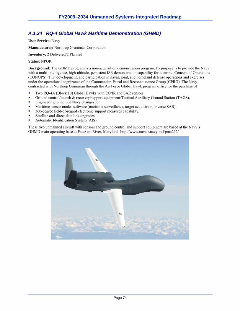
FY2009–2034 Unmanned Systems Integrated Roadmap
Page 74
A.1.24 RQ-4 Global Hawk Maritime Demonstration (GHMD) User Service: Navy
Manufacturer: Northrop Grumman Corporation
Inventory: 2 Delivered/2 Planned
Status: NPOR
Background: The GHMD program is a non-acquisition demonstration program. Its purpose is to provide the Navy with a multi-intelligence, high-altitude, persistent ISR demonstration capability for doctrine; Concept of Operations (CONOPS); TTP development; and participation in naval, joint, and homeland defense operations and exercises under the operational cognizance of the Commander, Patrol and Reconnaissance Group (CPRG). The Navy contracted with Northrop Grumman through the Air Force Global Hawk program office for the purchase of
Two RQ-4A (Block 10) Global Hawks with EO/IR and SAR sensors, Ground control/launch & recovery/support equipment/Tactical Auxiliary Ground Station (TAGS), Engineering to include Navy changes for Maritime sensor modes software (maritime surveillance, target acquisition, inverse SAR), 360-degree field-of-regard electronic support measures capability, Satellite and direct data link upgrades, Automatic Identification System (AIS).
These two unmanned aircraft with sensors and ground control and support equipment are based at the Navy’s GHMD main operating base at Patuxent River, Maryland. http://www.navair.navy.mil/pma262/
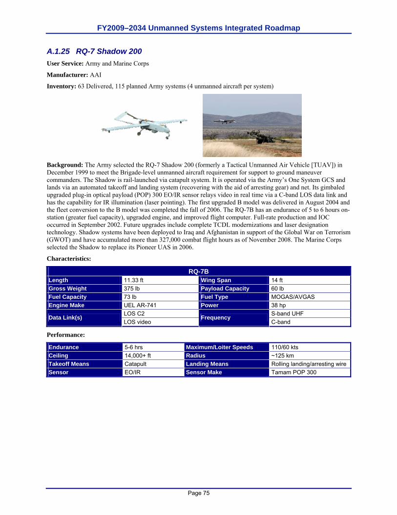
FY2009–2034 Unmanned Systems Integrated Roadmap
Page 75
A.1.25 RQ-7 Shadow 200 User Service: Army and Marine Corps
Manufacturer: AAI
Inventory: 63 Delivered, 115 planned Army systems (4 unmanned aircraft per system)
Background: The Army selected the RQ-7 Shadow 200 (formerly a Tactical Unmanned Air Vehicle [TUAV]) in December 1999 to meet the Brigade-level unmanned aircraft requirement for support to ground maneuver commanders. The Shadow is rail-launched via catapult system. It is operated via the Army’s One System GCS and lands via an automated takeoff and landing system (recovering with the aid of arresting gear) and net. Its gimbaled upgraded plug-in optical payload (POP) 300 EO/IR sensor relays video in real time via a C-band LOS data link and has the capability for IR illumination (laser pointing). The first upgraded B model was delivered in August 2004 and the fleet conversion to the B model was completed the fall of 2006. The RQ-7B has an endurance of 5 to 6 hours on-station (greater fuel capacity), upgraded engine, and improved flight computer. Full-rate production and IOC occurred in September 2002. Future upgrades include complete TCDL modernizations and laser designation technology. Shadow systems have been deployed to Iraq and Afghanistan in support of the Global War on Terrorism (GWOT) and have accumulated more than 327,000 combat flight hours as of November 2008. The Marine Corps selected the Shadow to replace its Pioneer UAS in 2006.
Characteristics:
RQ-7B Length 11.33 ft Wing Span 14 ft Gross Weight 375 lb Payload Capacity 60 lb Fuel Capacity 73 lb Fuel Type MOGAS/AVGAS Engine Make UEL AR-741 Power 38 hp
LOS C2 S-band UHF Data Link(s) LOS video
Frequency C-band
Performance:
Endurance 5-6 hrs Maximum/Loiter Speeds 110/60 kts Ceiling 14,000+ ft Radius ~125 km Takeoff Means Catapult Landing Means Rolling landing/arresting wire Sensor EO/IR Sensor Make Tamam POP 300
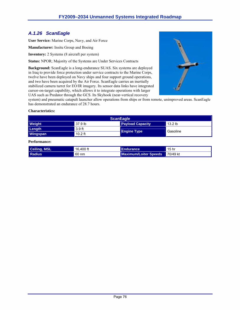
FY2009–2034 Unmanned Systems Integrated Roadmap
Page 76
A.1.26 ScanEagle User Service: Marine Corps, Navy, and Air Force
Manufacturer: Insitu Group and Boeing
Inventory: 2 Systems (8 aircraft per system)
Status: NPOR; Majority of the Systems are Under Services Contracts
Background: ScanEagle is a long-endurance SUAS. Six systems are deployed in Iraq to provide force protection under service contracts to the Marine Corps, twelve have been deployed on Navy ships and four support ground operations, and two have been acquired by the Air Force. ScanEagle carries an inertially stabilized camera turret for EO/IR imagery. Its sensor data links have integrated cursor-on-target capability, which allows it to integrate operations with larger UAS such as Predator through the GCS. Its Skyhook (near-vertical recovery system) and pneumatic catapult launcher allow operations from ships or from remote, unimproved areas. ScanEagle has demonstrated an endurance of 28.7 hours.
Characteristics:
ScanEagle Weight 37.9 lb Payload Capacity 13.2 lb Length 3.9 ft Wingspan 10.2 ft
Engine Type Gasoline
Performance:
Ceiling, MSL 16,400 ft Endurance 15 hr Radius 60 nm Maximum/Loiter Speeds 70/49 kt

FY2009–2034 Unmanned Systems Integrated Roadmap
Page 77
A.1.27 Silver Fox User Service: Navy, Marine Corps, Army
Manufacturer: Advanced Ceramics Research (ACR)
Inventory: 17 Systems Planned (54 total aircraft)
Status: NPOR; Evaluation Complete
Background: Silver Fox is a modular unmanned aircraft capable of running on either motor gasoline (MOGAS). The ONR tested its utility for ship security and harbor patrol. It has demonstrated an endurance of 8 hours and control of four airborne aircraft simultaneously. Canada’s armed forces have completed a joint evaluation.
Characteristics:
Silver Fox Weight 20 lb Payload Capacity 5 lb Length 4.8 ft Wingspan 7.8 ft
Engine Type gasoline
Performance:
Ceiling, MSL 16,000 ft Radius 20 nm
Endurance 8 hr
FY2009–2034 Unmanned Systems Integrated Roadmap
Page 78
A.1.28 Small Tactical UAS (STUAS)/Tier II UAS User Service: Navy and Marine Corps
Manufacturer: TBD
Inventory: TBD
Status: Awaiting RFP Release
Background: The STUAS/Tier II UAS program plans to enter the SDD phase of the acquisition process as an ACAT III program per SECNAVINST 5000.2C. STUAS/Tier II UAS is a new start program that will provide persistent ISR support for tactical-level maneuver decisions and unit-level force defense and force protection for Navy ships and Marine Corps land forces. This system will fill the ISR capability shortfalls identified by the Navy STUAS and Marine Corps Tier II UAS efforts and delineated in the JROC-approved Joint Tier II Initial Capabilities Document (ICD), which was validated in January 2007. This Joint ICD incorporates Marine Corps, Navy, Air Force, and SOCOM inputs identifying a joint capability gap set. Consisting of four air vehicles, two GCS, multi-mission (plug-and-play) payloads, and associated launch, recovery, and support equipment, this system will support Navy missions, including building the recognized maritime picture, maritime security operations, maritime interdiction operations, and support of Navy units operating from sea or shore. Marine Corps Tier II UAS will provide a small, organic, tactical ISR/Target Acquisition capability to the battalion/regimental/division/ Marine Expeditionary Unit commander and enable enhanced decision making and improved integration with ground schemes of maneuver.
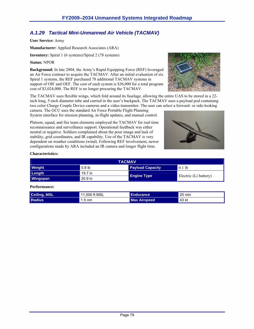
FY2009–2034 Unmanned Systems Integrated Roadmap
Page 79
A.1.29 Tactical Mini-Unmanned Air Vehicle (TACMAV) User Service: Army
Manufacturer: Applied Research Associates (ARA)
Inventory: Spiral 1 (6 systems)/Spiral 2 (78 systems)
Status: NPOR
Background: In late 2004, the Army’s Rapid Equipping Force (REF) leveraged an Air Force contract to acquire the TACMAV. After an initial evaluation of six Spiral 1 systems, the REF purchased 78 additional TACMAV systems in support of OIF and OEF. The cost of each system is $36,000 for a total program cost of $3,024,000. The REF is no longer procuring the TACMAV.
The TACMAV uses flexible wings, which fold around its fuselage, allowing the entire UAS to be stored in a 22-inch long, 5-inch diameter tube and carried in the user’s backpack. The TACMAV uses a payload pod containing two color Charge Couple Device cameras and a video transmitter. The user can select a forward- or side-looking camera. The GCU uses the standard Air Force Portable Flight Planning System interface for mission planning, in-flight updates, and manual control.
Platoon, squad, and fire team elements employed the TACMAV for real-time reconnaissance and surveillance support. Operational feedback was either neutral or negative. Soldiers complained about the poor image and lack of stability, grid coordinates, and IR capability. Use of the TACMAV is very dependent on weather conditions (wind). Following REF involvement, newer configurations made by ARA included an IR camera and longer flight time.
Characteristics:
TACMAV Weight 0.8 lb Payload Capacity 0.1 lb Length 19.7 in Wingspan 20.9 in
Engine Type Electric (Li battery)
Performance:
Ceiling, MSL 11,000 ft MSL Endurance 25 min Radius 1.5 nm Max Airspeed 43 kt
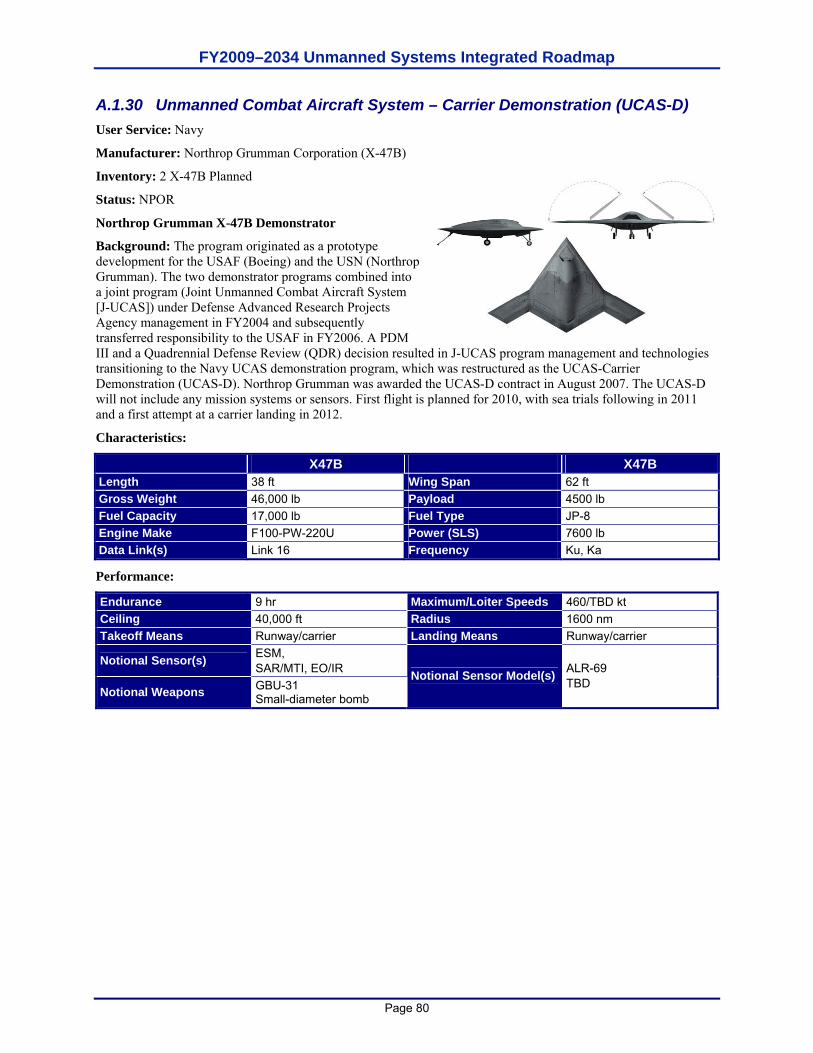
FY2009–2034 Unmanned Systems Integrated Roadmap
Page 80
A.1.30 Unmanned Combat Aircraft System – Carrier Demonstration (UCAS-D) User Service: Navy
Manufacturer: Northrop Grumman Corporation (X-47B)
Inventory: 2 X-47B Planned
Status: NPOR
Northrop Grumman X-47B Demonstrator
Background: The program originated as a prototype development for the USAF (Boeing) and the USN (Northrop Grumman). The two demonstrator programs combined into a joint program (Joint Unmanned Combat Aircraft System [J-UCAS]) under Defense Advanced Research Projects Agency management in FY2004 and subsequently transferred responsibility to the USAF in FY2006. A PDM III and a Quadrennial Defense Review (QDR) decision resulted in J-UCAS program management and technologies transitioning to the Navy UCAS demonstration program, which was restructured as the UCAS-Carrier Demonstration (UCAS-D). Northrop Grumman was awarded the UCAS-D contract in August 2007. The UCAS-D will not include any mission systems or sensors. First flight is planned for 2010, with sea trials following in 2011 and a first attempt at a carrier landing in 2012.
Characteristics:
X47B X47B Length 38 ft Wing Span 62 ft Gross Weight 46,000 lb Payload 4500 lb Fuel Capacity 17,000 lb Fuel Type JP-8 Engine Make F100-PW-220U Power (SLS) 7600 lb Data Link(s) Link 16 Frequency Ku, Ka
Performance:
Endurance 9 hr Maximum/Loiter Speeds 460/TBD kt Ceiling 40,000 ft Radius 1600 nm Takeoff Means Runway/carrier Landing Means Runway/carrier
Notional Sensor(s) ESM, SAR/MTI, EO/IR
Notional Weapons GBU-31 Small-diameter bomb
Notional Sensor Model(s) ALR-69 TBD
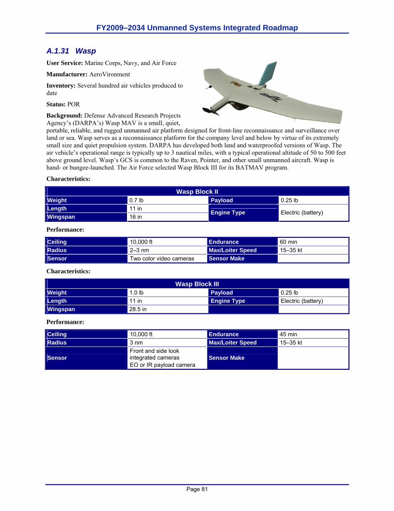
FY2009–2034 Unmanned Systems Integrated Roadmap
Page 81
A.1.31 Wasp User Service: Marine Corps, Navy, and Air Force
Manufacturer: AeroVironment
Inventory: Several hundred air vehicles produced to date
Status: POR
Background: Defense Advanced Research Projects Agency’s (DARPA’s) Wasp MAV is a small, quiet, portable, reliable, and rugged unmanned air platform designed for front-line reconnaissance and surveillance over land or sea. Wasp serves as a reconnaissance platform for the company level and below by virtue of its extremely small size and quiet propulsion system. DARPA has developed both land and waterproofed versions of Wasp. The air vehicle’s operational range is typically up to 3 nautical miles, with a typical operational altitude of 50 to 500 feet above ground level. Wasp’s GCS is common to the Raven, Pointer, and other small unmanned aircraft. Wasp is hand- or bungee-launched. The Air Force selected Wasp Block III for its BATMAV program.
Characteristics:
Wasp Block II Weight 0.7 lb Payload 0.25 lb Length 11 in Wingspan 16 in
Engine Type Electric (battery)
Performance:
Ceiling 10,000 ft Endurance 60 min Radius 2–3 nm Max/Loiter Speed 15–35 kt Sensor Two color video cameras Sensor Make
Characteristics:
Wasp Block III Weight 1.0 lb Payload 0.25 lb Length 11 in Engine Type Electric (battery) Wingspan 28.5 in
Performance:
Ceiling 10,000 ft Endurance 45 min Radius 3 nm Max/Loiter Speed 15–35 kt
Sensor Front and side look integrated cameras EO or IR payload camera
Sensor Make
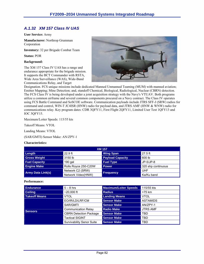
FY2009–2034 Unmanned Systems Integrated Roadmap
Page 82
A.1.32 XM 157 Class IV UAS User Service: Army
Manufacturer: Northrop Grumman Corporation
Inventory: 32 per Brigade Combat Team
Status: POR
Background:
The XM 157 Class IV UAS has a range and endurance appropriate for the brigade mission. It supports the BCT Commander with RSTA, Wide Area Surveillance (WAS), Wide-Band Communications Relay, and Target Designation. FCS unique missions include dedicated Manned Unmanned Teaming (MUM) with manned aviation; Emitter Mapping; Mine Detection; and, standoff Chemical, Biological, Radiological, Nuclear (CBRN) detection. The FCS Class IV is being developed under a joint acquisition strategy with the Navy's VTUAV. Both programs utilize a common airframe and several common components procured on a Navy contract. The Class IV operates using FCS Battle Command and SoSCOE software. Communication payloads include JTRS SFF-J (SRW) radios for command and control, WIN-T JC4ISR (HNW) radio for payload data, and JTRS AMF (HNW & WNW) radio for communications relay. Key program dates: CDR 3QFY11, First Flight 2QFY11, Limited User Test 1QFY13 and IOC 3QFY15.
Maximum/Loiter Speeds: 115/55 kts
Takeoff Means: VTOL
Landing Means: VTOL
(SAR/GMTI) Sensor Make: AN/ZPY-1
Characteristics:
XM 157 Length 22.9 ft Wing Span 27.5 ft Gross Weight 3150 lb Payload Capacity 600 lb Fuel Capacity 190 gal Fuel Type JP-5/JP-8 Engine Make Rolls Royce 250-C20W Power 320 shp continuous
Network C2 (SRW) UHF Army Data Link(s) Network Video(HNW)
Frequency Ka/Ku band
Performance:
Endurance 5 – 8 hrs Maximum/Loiter Speeds 115/55 kts Ceiling ~20,000 ft Radius >75 km Takeoff Means VTOL Landing Means VTOL
EO/IR/LD/LRF/CM Sensor Make ASTAMIDS SAR/GMTI Sensor Make AN/ZPY-1 Communication Relay Radio Make JTRS AMF CBRN Detection Package Sensor Make TBD Tactical SIGINT Sensor Make TBD
Sensors
Survivability Senor Suite Sensor Make TBD
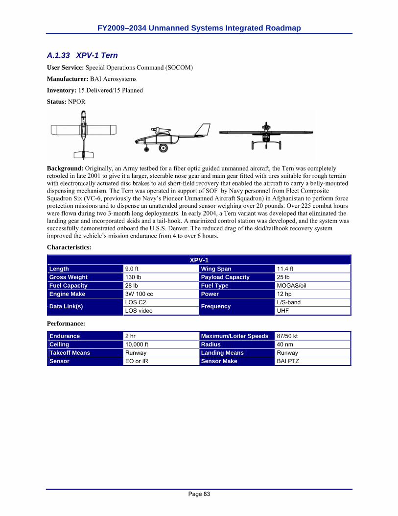
FY2009–2034 Unmanned Systems Integrated Roadmap
Page 83
A.1.33 XPV-1 Tern User Service: Special Operations Command (SOCOM)
Manufacturer: BAI Aerosystems
Inventory: 15 Delivered/15 Planned
Status: NPOR
Background: Originally, an Army testbed for a fiber optic guided unmanned aircraft, the Tern was completely retooled in late 2001 to give it a larger, steerable nose gear and main gear fitted with tires suitable for rough terrain with electronically actuated disc brakes to aid short-field recovery that enabled the aircraft to carry a belly-mounted dispensing mechanism. The Tern was operated in support of SOF by Navy personnel from Fleet Composite Squadron Six (VC-6, previously the Navy’s Pioneer Unmanned Aircraft Squadron) in Afghanistan to perform force protection missions and to dispense an unattended ground sensor weighing over 20 pounds. Over 225 combat hours were flown during two 3-month long deployments. In early 2004, a Tern variant was developed that eliminated the landing gear and incorporated skids and a tail-hook. A marinized control station was developed, and the system was successfully demonstrated onboard the U.S.S. Denver. The reduced drag of the skid/tailhook recovery system improved the vehicle’s mission endurance from 4 to over 6 hours.
Characteristics:
XPV-1 Length 9.0 ft Wing Span 11.4 ft Gross Weight 130 lb Payload Capacity 25 lb Fuel Capacity 28 lb Fuel Type MOGAS/oil Engine Make 3W 100 cc Power 12 hp
LOS C2 L/S-band Data Link(s) LOS video
Frequency UHF
Performance:
Endurance 2 hr Maximum/Loiter Speeds 87/50 kt Ceiling 10,000 ft Radius 40 nm Takeoff Means Runway Landing Means Runway Sensor EO or IR Sensor Make BAI PTZ
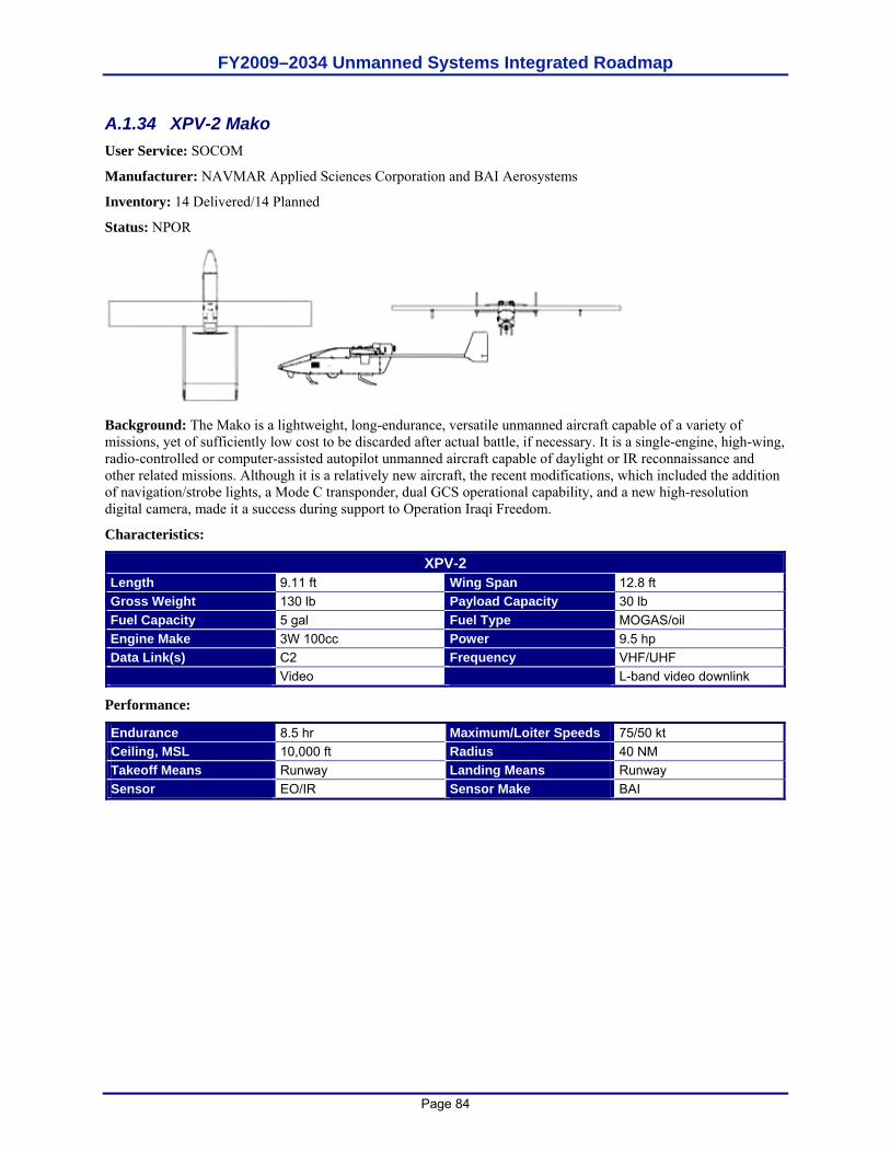
FY2009–2034 Unmanned Systems Integrated Roadmap
Page 84
A.1.34 XPV-2 Mako User Service: SOCOM
Manufacturer: NAVMAR Applied Sciences Corporation and BAI Aerosystems
Inventory: 14 Delivered/14 Planned
Status: NPOR
Background: The Mako is a lightweight, long-endurance, versatile unmanned aircraft capable of a variety of missions, yet of sufficiently low cost to be discarded after actual battle, if necessary. It is a single-engine, high-wing, radio-controlled or computer-assisted autopilot unmanned aircraft capable of daylight or IR reconnaissance and other related missions. Although it is a relatively new aircraft, the recent modifications, which included the addition of navigation/strobe lights, a Mode C transponder, dual GCS operational capability, and a new high-resolution digital camera, made it a success during support to Operation Iraqi Freedom.
Characteristics:
XPV-2 Length 9.11 ft Wing Span 12.8 ft Gross Weight 130 lb Payload Capacity 30 lb Fuel Capacity 5 gal Fuel Type MOGAS/oil Engine Make 3W 100cc Power 9.5 hp Data Link(s) C2 Frequency VHF/UHF Video L-band video downlink
Performance:
Endurance 8.5 hr Maximum/Loiter Speeds 75/50 kt Ceiling, MSL 10,000 ft Radius 40 NM Takeoff Means Runway Landing Means Runway Sensor EO/IR Sensor Make BAI
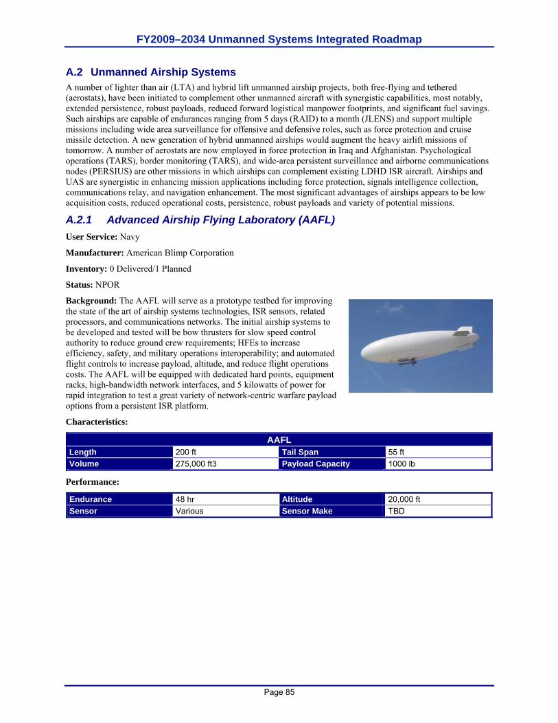
FY2009–2034 Unmanned Systems Integrated Roadmap
Page 85
A.2 Unmanned Airship Systems A number of lighter than air (LTA) and hybrid lift unmanned airship projects, both free-flying and tethered (aerostats), have been initiated to complement other unmanned aircraft with synergistic capabilities, most notably, extended persistence, robust payloads, reduced forward logistical manpower footprints, and significant fuel savings. Such airships are capable of endurances ranging from 5 days (RAID) to a month (JLENS) and support multiple missions including wide area surveillance for offensive and defensive roles, such as force protection and cruise missile detection. A new generation of hybrid unmanned airships would augment the heavy airlift missions of tomorrow. A number of aerostats are now employed in force protection in Iraq and Afghanistan. Psychological operations (TARS), border monitoring (TARS), and wide-area persistent surveillance and airborne communications nodes (PERSIUS) are other missions in which airships can complement existing LDHD ISR aircraft. Airships and UAS are synergistic in enhancing mission applications including force protection, signals intelligence collection, communications relay, and navigation enhancement. The most significant advantages of airships appears to be low acquisition costs, reduced operational costs, persistence, robust payloads and variety of potential missions.
A.2.1 Advanced Airship Flying Laboratory (AAFL) User Service: Navy
Manufacturer: American Blimp Corporation
Inventory: 0 Delivered/1 Planned
Status: NPOR
Background: The AAFL will serve as a prototype testbed for improving the state of the art of airship systems technologies, ISR sensors, related processors, and communications networks. The initial airship systems to be developed and tested will be bow thrusters for slow speed control authority to reduce ground crew requirements; HFEs to increase efficiency, safety, and military operations interoperability; and automated flight controls to increase payload, altitude, and reduce flight operations costs. The AAFL will be equipped with dedicated hard points, equipment racks, high-bandwidth network interfaces, and 5 kilowatts of power for rapid integration to test a great variety of network-centric warfare payload options from a persistent ISR platform.
Characteristics:
AAFL Length 200 ft Tail Span 55 ft Volume 275,000 ft3 Payload Capacity 1000 lb
Performance:
Endurance 48 hr Altitude 20,000 ft Sensor Various Sensor Make TBD

FY2009–2034 Unmanned Systems Integrated Roadmap
Page 86
A.2.2 Hybrid Unmanned Aircraft Vehicle (HUAV) Persistent Elevated Reconnaissance Surveillance Intelligence Unmanned System (PERSIUS) User Service: JOINT
Manufacturer: Lockheed Martin Aeronautics, Advanced Development Programs (ADP)
Inventory: 0 Delivered / 1 Planned (JCTD)/ 1 IRAD Proof-of-Concept Demo Vehicle
Status: Under construction. First delivery in December 2009.
Program Background: Background: PERSIUS, Persistent Elevated Reconnaissance Surveillance Intelligence Unmanned System, is a first generation HUAV, a revolutionary hybrid buoyant lift aircraft providing near term, affordable, persistent ISR options in an ever-changing GWOT world. PERSIUS employs a versatile, non-proprietary, ‘payload gondola,’ populated with mission specific payloads, integrated and tested independent of the aircraft and easily maintained and reconfigured. PERSIUS will operate for 2-3 weeks at 20,000 ft with a 2,500 payload without recovering, thus reducing launches and recoveries, maintenance and forward deployed manpower. Hybrid lift augments traditional lift requiring less thrust and achieving much greater fuel efficiency. PERSIUS is a 2009 JCTD initiative to advance affordable, near-term, persistent ISR and communications solutions for multiple COCOM requirements
Characteristics:
HUAV/PERSIUS Length 250 ft Tail Span ~110 ft Volume 975,000 ft3 Payload Capacity 2,500 lb at 20,000 ft
Performance:
Endurance 21 Days Altitude 20,000 ft Sensor Various Sensor Make TBD
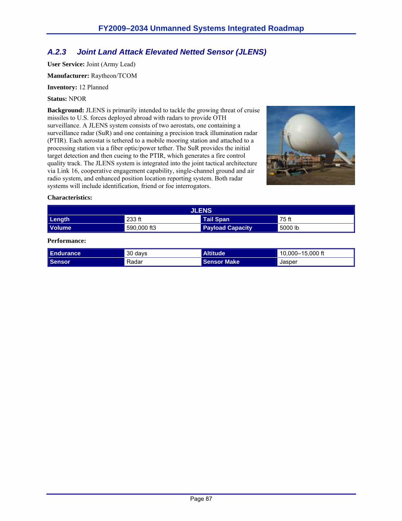
FY2009–2034 Unmanned Systems Integrated Roadmap
Page 87
A.2.3 Joint Land Attack Elevated Netted Sensor (JLENS) User Service: Joint (Army Lead)
Manufacturer: Raytheon/TCOM
Inventory: 12 Planned
Status: NPOR
Background: JLENS is primarily intended to tackle the growing threat of cruise missiles to U.S. forces deployed abroad with radars to provide OTH surveillance. A JLENS system consists of two aerostats, one containing a surveillance radar (SuR) and one containing a precision track illumination radar (PTIR). Each aerostat is tethered to a mobile mooring station and attached to a processing station via a fiber optic/power tether. The SuR provides the initial target detection and then cueing to the PTIR, which generates a fire control quality track. The JLENS system is integrated into the joint tactical architecture via Link 16, cooperative engagement capability, single-channel ground and air radio system, and enhanced position location reporting system. Both radar systems will include identification, friend or foe interrogators.
Characteristics:
JLENS Length 233 ft Tail Span 75 ft Volume 590,000 ft3 Payload Capacity 5000 lb
Performance:
Endurance 30 days Altitude 10,000–15,000 ft Sensor Radar Sensor Make Jasper
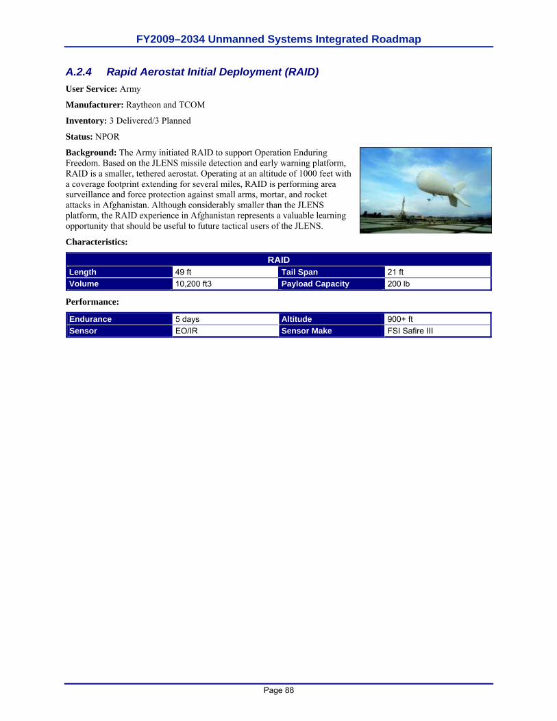
FY2009–2034 Unmanned Systems Integrated Roadmap
Page 88
A.2.4 Rapid Aerostat Initial Deployment (RAID) User Service: Army
Manufacturer: Raytheon and TCOM
Inventory: 3 Delivered/3 Planned
Status: NPOR
Background: The Army initiated RAID to support Operation Enduring Freedom. Based on the JLENS missile detection and early warning platform, RAID is a smaller, tethered aerostat. Operating at an altitude of 1000 feet with a coverage footprint extending for several miles, RAID is performing area surveillance and force protection against small arms, mortar, and rocket attacks in Afghanistan. Although considerably smaller than the JLENS platform, the RAID experience in Afghanistan represents a valuable learning opportunity that should be useful to future tactical users of the JLENS.
Characteristics:
RAID Length 49 ft Tail Span 21 ft Volume 10,200 ft3 Payload Capacity 200 lb
Performance:
Endurance 5 days Altitude 900+ ft Sensor EO/IR Sensor Make FSI Safire III
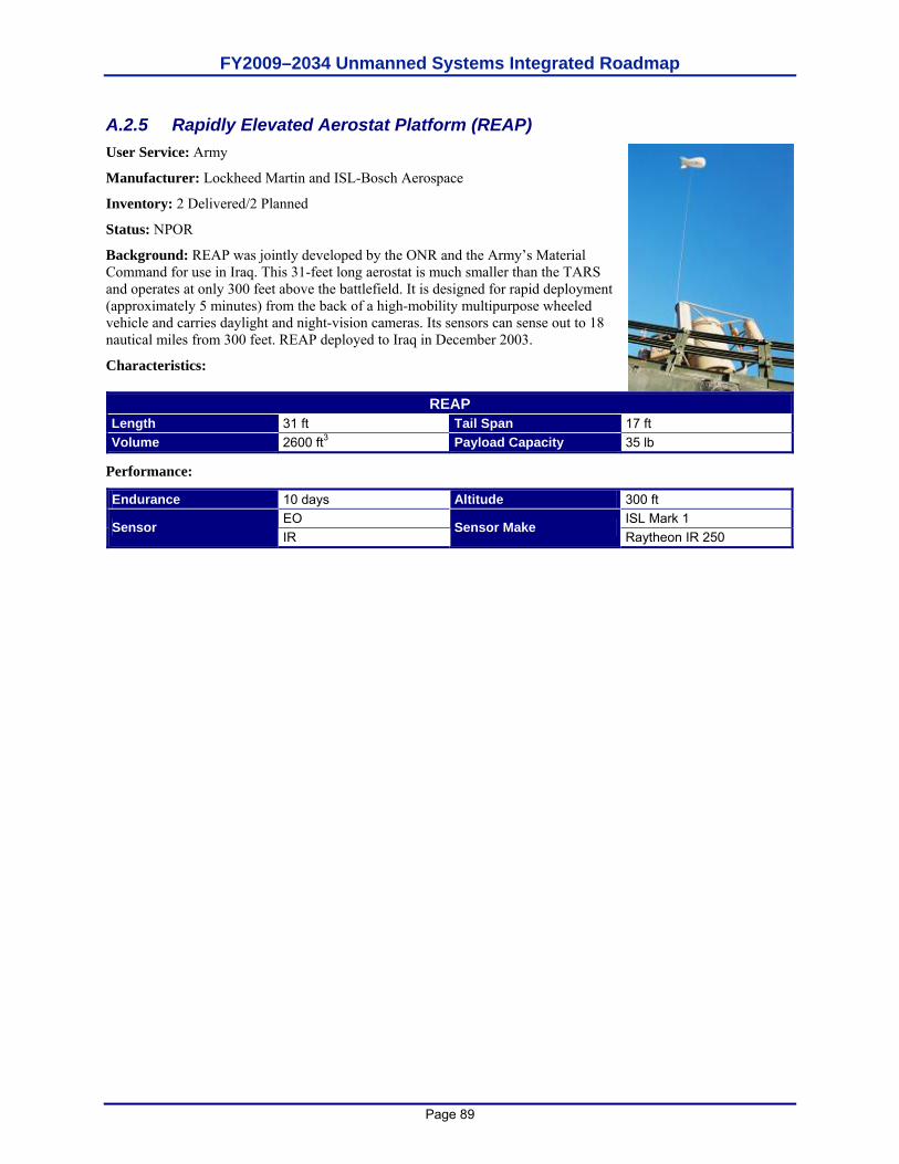
FY2009–2034 Unmanned Systems Integrated Roadmap
Page 89
A.2.5 Rapidly Elevated Aerostat Platform (REAP) User Service: Army
Manufacturer: Lockheed Martin and ISL-Bosch Aerospace
Inventory: 2 Delivered/2 Planned
Status: NPOR
Background: REAP was jointly developed by the ONR and the Army’s Material Command for use in Iraq. This 31-feet long aerostat is much smaller than the TARS and operates at only 300 feet above the battlefield. It is designed for rapid deployment (approximately 5 minutes) from the back of a high-mobility multipurpose wheeled vehicle and carries daylight and night-vision cameras. Its sensors can sense out to 18 nautical miles from 300 feet. REAP deployed to Iraq in December 2003.
Characteristics:
REAP Length 31 ft Tail Span 17 ft Volume 2600 ft3 Payload Capacity 35 lb
Performance:
Endurance 10 days Altitude 300 ft EO ISL Mark 1 Sensor IR
Sensor Make Raytheon IR 250
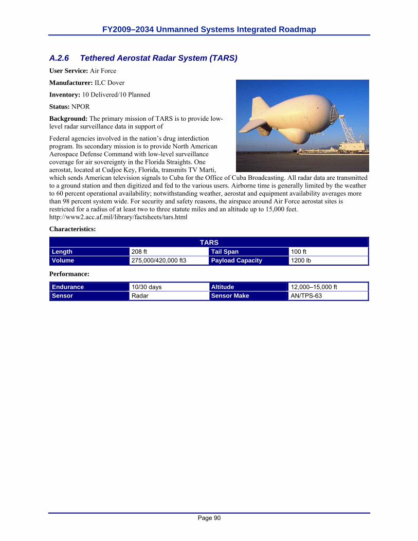
FY2009–2034 Unmanned Systems Integrated Roadmap
Page 90
A.2.6 Tethered Aerostat Radar System (TARS) User Service: Air Force
Manufacturer: ILC Dover
Inventory: 10 Delivered/10 Planned
Status: NPOR
Background: The primary mission of TARS is to provide low-level radar surveillance data in support of
Federal agencies involved in the nation’s drug interdiction program. Its secondary mission is to provide North American Aerospace Defense Command with low-level surveillance coverage for air sovereignty in the Florida Straights. One aerostat, located at Cudjoe Key, Florida, transmits TV Marti, which sends American television signals to Cuba for the Office of Cuba Broadcasting. All radar data are transmitted to a ground station and then digitized and fed to the various users. Airborne time is generally limited by the weather to 60 percent operational availability; notwithstanding weather, aerostat and equipment availability averages more than 98 percent system wide. For security and safety reasons, the airspace around Air Force aerostat sites is restricted for a radius of at least two to three statute miles and an altitude up to 15,000 feet. http://www2.acc.af.mil/library/factsheets/tars.html
Characteristics:
TARS Length 208 ft Tail Span 100 ft Volume 275,000/420,000 ft3 Payload Capacity 1200 lb
Performance:
Endurance 10/30 days Altitude 12,000–15,000 ft Sensor Radar Sensor Make AN/TPS-63
FY2009–2034 Unmanned Systems Integrated Roadmap
Page 91
A.3 Unmanned Aircraft System (UAS) Airspace Integration A.3.1 Overview The OSD vision is to have “File and Fly” access for appropriately equipped UAS by the end of 2012 while maintaining an equivalent level of safety (ELOS) to aircraft with a pilot onboard. For military operations, UAS will operate with manned aircraft in civil airspace, including in and around airfields, using concepts of operation that make on- or off-board distinctions transparent to ATC authorities and airspace regulators. The operations tempo at mixed airfields will not be diminished by the integration of unmanned aviation.
Historically, UAS were predominately operated by DoD in support of combat operations in military controlled airspace; however, UAS support to civil authorities (JTF Katrina in 2005, U.S. Border surveillance, and fire suppression) continues to expand. This expansion, coupled with the requirement to train and operate DoD and OGA assets, highlights the need for routine access to the NAS outside of restricted and warning areas, over land and water. Additionally, operating UAS in other host nation airspace systems emphasizes the need to resolve airspace integration concerns as soon as practical.
A.3.2 Background Because the current UAS do not have the same capabilities as manned aircraft to safely and efficiently integrate into the NAS, military UAS requirements to operate outside of restricted and warning areas are accommodated on a case-by-case basis. A process used to gain NAS access was jointly developed and agreed to by the DoD and Federal Aviation Administration (FAA) in 1999. Military operators of UAS are required to obtain a COA from the FAA. The process can take up to 60 days and, because UAS do not have a see and avoid (S&A) capability, may require such additional and costly measures as providing chase planes and/or primary radar coverage. COAs are typically issued for a specific UAS, limited to specific routes or areas, and are valid for no more than one year. Exceptions are the National COA that was issued to the Air Force for Global Hawk operations in the NAS and the Disaster Relief COA that was issued to NORTHCOM’s Joint Force Air Component Commander for the Predator and Global Hawk UAS along the southern and northern borders.
With a COA, the UAS is accommodated into the system when mission needs dictate; however, because the UAS lacks the ability to meet the same regulator requirements as a manned aircraft, it is frequently segregated from manned aviation rather than integrated with it, an exception being the integration of UAS flying on Instrument Flight Rules (IFR) flight plans. As the DoD CONOPS for UAS matures and as we ensure the airworthiness of our UAS, we will look toward developing new procedures to gain access to the NAS. Toward that end, the DoD is working with the FAA to refine and/or replace the COA process to enable more ready access to the NAS for qualified UAS.
From the DoD perspective, three critical issues must be addressed in order to supplant the COA process: UAS reliability, FAA regulations, and an S&A capability. Each is discussed here.
OSD and FAA, working through the DoD Policy Board on Federal Aviation (PBFA), are engaged in establishing the air traffic regulatory infrastructure for integrating military UAS into the NAS. By limiting this effort’s focus to traffic management of domestic flight operations by military UAS, the hope is to establish a solid precedent that can be extended to other public and civil UAS domestically and to civil and military flights in international and non-U.S. airspace. As depicted in Figure A.1, this initiative (shown by the lower-left block in the figure) is intended
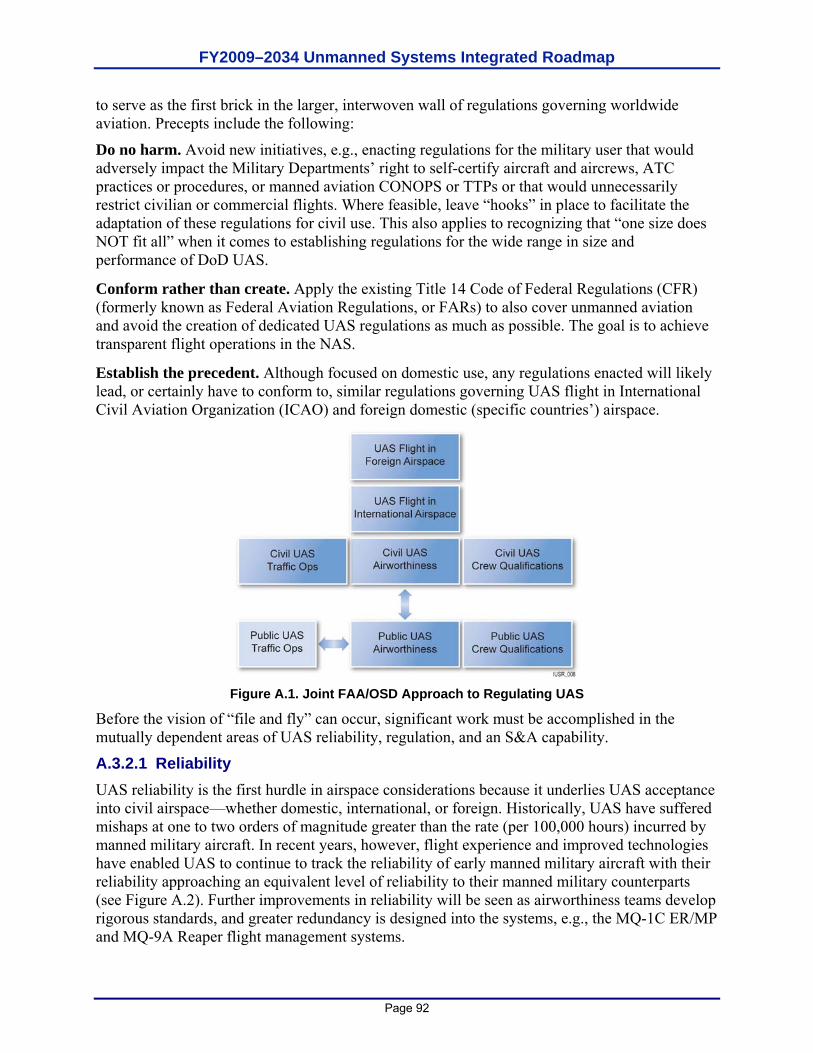
FY2009–2034 Unmanned Systems Integrated Roadmap
Page 92
to serve as the first brick in the larger, interwoven wall of regulations governing worldwide aviation. Precepts include the following:
Do no harm. Avoid new initiatives, e.g., enacting regulations for the military user that would adversely impact the Military Departments’ right to self-certify aircraft and aircrews, ATC practices or procedures, or manned aviation CONOPS or TTPs or that would unnecessarily restrict civilian or commercial flights. Where feasible, leave “hooks” in place to facilitate the adaptation of these regulations for civil use. This also applies to recognizing that “one size does NOT fit all” when it comes to establishing regulations for the wide range in size and performance of DoD UAS.
Conform rather than create. Apply the existing Title 14 Code of Federal Regulations (CFR) (formerly known as Federal Aviation Regulations, or FARs) to also cover unmanned aviation and avoid the creation of dedicated UAS regulations as much as possible. The goal is to achieve transparent flight operations in the NAS.
Establish the precedent. Although focused on domestic use, any regulations enacted will likely lead, or certainly have to conform to, similar regulations governing UAS flight in International Civil Aviation Organization (ICAO) and foreign domestic (specific countries’) airspace.
Figure A.1. Joint FAA/OSD Approach to Regulating UAS
Before the vision of “file and fly” can occur, significant work must be accomplished in the mutually dependent areas of UAS reliability, regulation, and an S&A capability.
A.3.2.1 Reliability UAS reliability is the first hurdle in airspace considerations because it underlies UAS acceptance into civil airspace—whether domestic, international, or foreign. Historically, UAS have suffered mishaps at one to two orders of magnitude greater than the rate (per 100,000 hours) incurred by manned military aircraft. In recent years, however, flight experience and improved technologies have enabled UAS to continue to track the reliability of early manned military aircraft with their reliability approaching an equivalent level of reliability to their manned military counterparts (see Figure A.2). Further improvements in reliability will be seen as airworthiness teams develop rigorous standards, and greater redundancy is designed into the systems, e.g., the MQ-1C ER/MP and MQ-9A Reaper flight management systems.
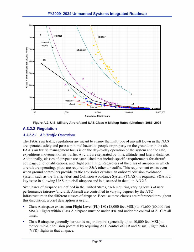
FY2009–2034 Unmanned Systems Integrated Roadmap
Page 93
Reaper0
100
200
300
400
500
600
700
100 1,000 10,000 100,000 1,000,000
Cumulative Flight Hours
Cla
ss A
or B
Mis
haps
per
100
,000
Hou
rs
Pioneer
U-2
Global Hawk
Hunter
Predator
F-16
Shadow
I-Gnat
Figure A.2. U.S. Military Aircraft and UAS Class A Mishap Rates (Lifetime), 1986–2006
A.3.2.2 Regulation A.3.2.2.1 Air Traffic Operations The FAA’s air traffic regulations are meant to ensure the multitude of aircraft flown in the NAS are operated safely and pose a minimal hazard to people or property on the ground or in the air. FAA’s air traffic management focus is on the day-to-day operation of the system and the safe, expeditious movement of air traffic. Aircraft are separated by time, altitude, and lateral distance. Additionally, classes of airspace are established that include specific requirements for aircraft equipage, pilot qualifications, and flight plan filing. Regardless of the class of airspace in which aircraft are operating, pilots are required to S&A other air traffic. This requirement exists even when ground controllers provide traffic advisories or when an onboard collision avoidance system, such as the Traffic Alert and Collision Avoidance System (TCAS), is required. S&A is a key issue in allowing UAS into civil airspace and is discussed in detail in A.3.2.3.
Six classes of airspace are defined in the United States, each requiring varying levels of user performance (aircrew/aircraft). Aircraft are controlled to varying degrees by the ATC infrastructure in the different classes of airspace. Because these classes are referenced throughout this discussion, a brief description is useful.
Class A airspace exists from Flight Level (FL) 180 (18,000 feet MSL) to FL600 (60,000 feet MSL). Flights within Class A airspace must be under IFR and under the control of ATC at all times.
Class B airspace generally surrounds major airports (generally up to 10,000 feet MSL) to reduce mid-air collision potential by requiring ATC control of IFR and Visual Flight Rules (VFR) flights in that airspace.
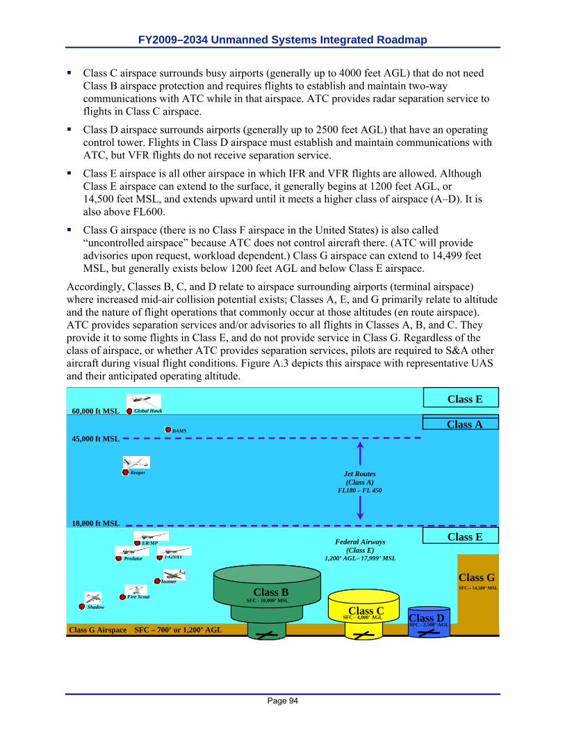
FY2009–2034 Unmanned Systems Integrated Roadmap
Page 94
Class C airspace surrounds busy airports (generally up to 4000 feet AGL) that do not need Class B airspace protection and requires flights to establish and maintain two-way communications with ATC while in that airspace. ATC provides radar separation service to flights in Class C airspace.
Class D airspace surrounds airports (generally up to 2500 feet AGL) that have an operating control tower. Flights in Class D airspace must establish and maintain communications with ATC, but VFR flights do not receive separation service.
Class E airspace is all other airspace in which IFR and VFR flights are allowed. Although Class E airspace can extend to the surface, it generally begins at 1200 feet AGL, or 14,500 feet MSL, and extends upward until it meets a higher class of airspace (A–D). It is also above FL600.
Class G airspace (there is no Class F airspace in the United States) is also called “uncontrolled airspace” because ATC does not control aircraft there. (ATC will provide advisories upon request, workload dependent.) Class G airspace can extend to 14,499 feet MSL, but generally exists below 1200 feet AGL and below Class E airspace.
Accordingly, Classes B, C, and D relate to airspace surrounding airports (terminal airspace) where increased mid-air collision potential exists; Classes A, E, and G primarily relate to altitude and the nature of flight operations that commonly occur at those altitudes (en route airspace). ATC provides separation services and/or advisories to all flights in Classes A, B, and C. They provide it to some flights in Class E, and do not provide service in Class G. Regardless of the class of airspace, or whether ATC provides separation services, pilots are required to S&A other aircraft during visual flight conditions. Figure A.3 depicts this airspace with representative UAS and their anticipated operating altitude.
Class G SFC
- 700
’
Class A
Class E
Class D
-
2,5000
’
MSL
Class B
SFC
-
10,000
’
MSL
Class C
SFC
-
4,000
’
MSL
Class E
60,000 ft MSL
18,000 ft MSL
Class E
Global Hawk
Reaper
Hunter
Shadow
I-GNAT
Predator
Fire Scout
Class C
SFC - 4,000’ AGL
ER/MP
Federal Airways
(Class E) 1,200’ AGL– 17,999’ MSL
Jet Routes (Class A)
FL180 – FL 450
45,000 ft MSL
Class G SFC – 14,500’ MSL
Class E
Class D SFC - 2,500’ AGL
Class B
SFC - 10,000’ MSL
Class A
BAMS
Class G Airspace SFC – 700’ or 1,200’ AGL
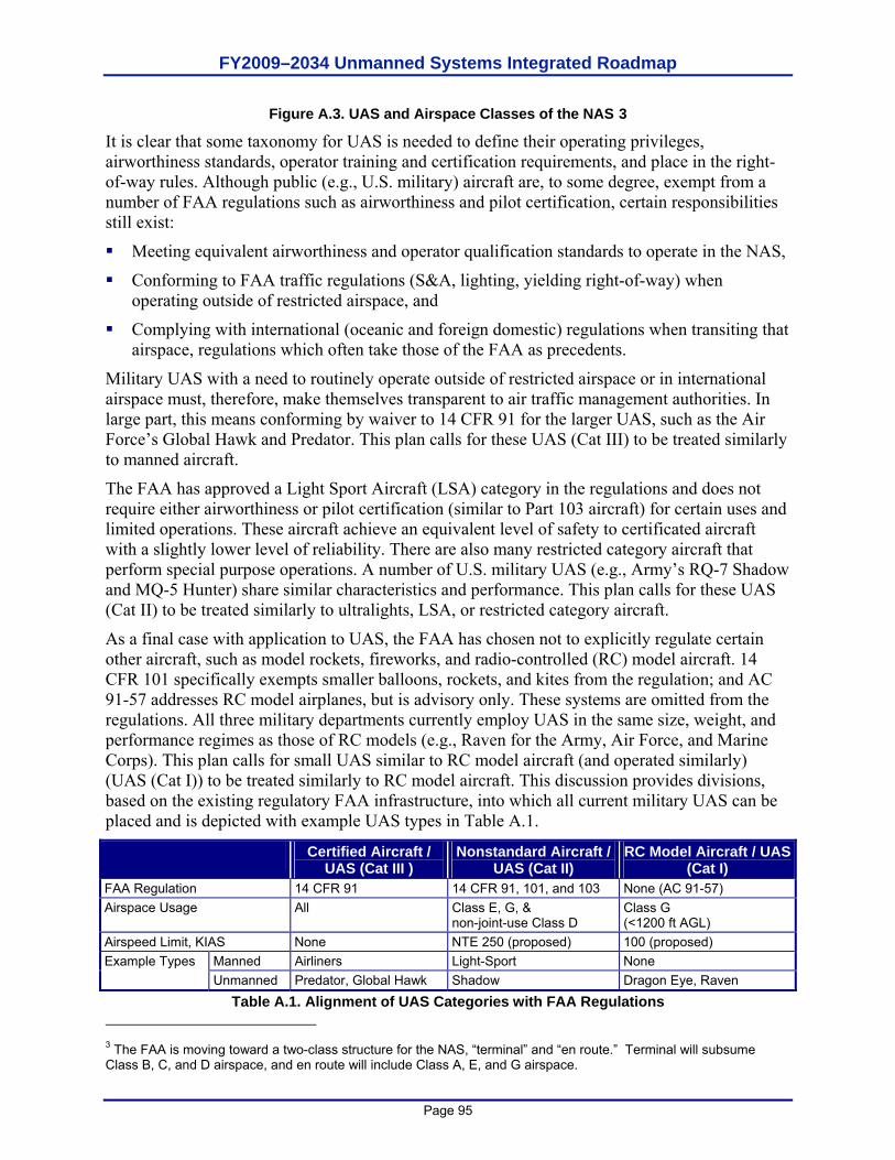
FY2009–2034 Unmanned Systems Integrated Roadmap
Page 95
Figure A.3. UAS and Airspace Classes of the NAS 3
It is clear that some taxonomy for UAS is needed to define their operating privileges, airworthiness standards, operator training and certification requirements, and place in the right-of-way rules. Although public (e.g., U.S. military) aircraft are, to some degree, exempt from a number of FAA regulations such as airworthiness and pilot certification, certain responsibilities still exist:
Meeting equivalent airworthiness and operator qualification standards to operate in the NAS,
Conforming to FAA traffic regulations (S&A, lighting, yielding right-of-way) when operating outside of restricted airspace, and
Complying with international (oceanic and foreign domestic) regulations when transiting that airspace, regulations which often take those of the FAA as precedents.
Military UAS with a need to routinely operate outside of restricted airspace or in international airspace must, therefore, make themselves transparent to air traffic management authorities. In large part, this means conforming by waiver to 14 CFR 91 for the larger UAS, such as the Air Force’s Global Hawk and Predator. This plan calls for these UAS (Cat III) to be treated similarly to manned aircraft.
The FAA has approved a Light Sport Aircraft (LSA) category in the regulations and does not require either airworthiness or pilot certification (similar to Part 103 aircraft) for certain uses and limited operations. These aircraft achieve an equivalent level of safety to certificated aircraft with a slightly lower level of reliability. There are also many restricted category aircraft that perform special purpose operations. A number of U.S. military UAS (e.g., Army’s RQ-7 Shadow and MQ-5 Hunter) share similar characteristics and performance. This plan calls for these UAS (Cat II) to be treated similarly to ultralights, LSA, or restricted category aircraft.
As a final case with application to UAS, the FAA has chosen not to explicitly regulate certain other aircraft, such as model rockets, fireworks, and radio-controlled (RC) model aircraft. 14 CFR 101 specifically exempts smaller balloons, rockets, and kites from the regulation; and AC 91-57 addresses RC model airplanes, but is advisory only. These systems are omitted from the regulations. All three military departments currently employ UAS in the same size, weight, and performance regimes as those of RC models (e.g., Raven for the Army, Air Force, and Marine Corps). This plan calls for small UAS similar to RC model aircraft (and operated similarly) (UAS (Cat I)) to be treated similarly to RC model aircraft. This discussion provides divisions, based on the existing regulatory FAA infrastructure, into which all current military UAS can be placed and is depicted with example UAS types in Table A.1.
Certified Aircraft / UAS (Cat III )
Nonstandard Aircraft / UAS (Cat II)
RC Model Aircraft / UAS (Cat I)
FAA Regulation 14 CFR 91 14 CFR 91, 101, and 103 None (AC 91-57) Airspace Usage All Class E, G, &
non-joint-use Class D Class G (<1200 ft AGL)
Airspeed Limit, KIAS None NTE 250 (proposed) 100 (proposed) Manned Airliners Light-Sport None Example Types Unmanned Predator, Global Hawk Shadow Dragon Eye, Raven
Table A.1. Alignment of UAS Categories with FAA Regulations 3 The FAA is moving toward a two-class structure for the NAS, “terminal” and “en route.” Terminal will subsume Class B, C, and D airspace, and en route will include Class A, E, and G airspace.
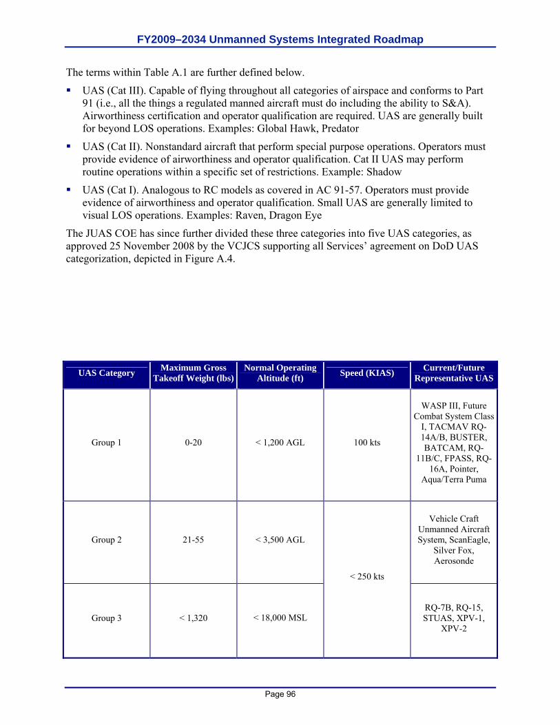
FY2009–2034 Unmanned Systems Integrated Roadmap
Page 96
The terms within Table A.1 are further defined below.
UAS (Cat III). Capable of flying throughout all categories of airspace and conforms to Part 91 (i.e., all the things a regulated manned aircraft must do including the ability to S&A). Airworthiness certification and operator qualification are required. UAS are generally built for beyond LOS operations. Examples: Global Hawk, Predator
UAS (Cat II). Nonstandard aircraft that perform special purpose operations. Operators must provide evidence of airworthiness and operator qualification. Cat II UAS may perform routine operations within a specific set of restrictions. Example: Shadow
UAS (Cat I). Analogous to RC models as covered in AC 91-57. Operators must provide evidence of airworthiness and operator qualification. Small UAS are generally limited to visual LOS operations. Examples: Raven, Dragon Eye
The JUAS COE has since further divided these three categories into five UAS categories, as approved 25 November 2008 by the VCJCS supporting all Services’ agreement on DoD UAS categorization, depicted in Figure A.4.
UAS Category Maximum Gross Takeoff Weight (lbs)
Normal Operating Altitude (ft) Speed (KIAS) Current/Future
Representative UAS
Group 1 0-20 < 1,200 AGL 100 kts
WASP III, Future Combat System Class
I, TACMAV RQ-14A/B, BUSTER, BATCAM, RQ-
11B/C, FPASS, RQ-16A, Pointer,
Aqua/Terra Puma
Group 2 21-55 < 3,500 AGL
Vehicle Craft Unmanned Aircraft System, ScanEagle,
Silver Fox, Aerosonde
Group 3 < 1,320 < 18,000 MSL
< 250 kts
RQ-7B, RQ-15, STUAS, XPV-1,
XPV-2
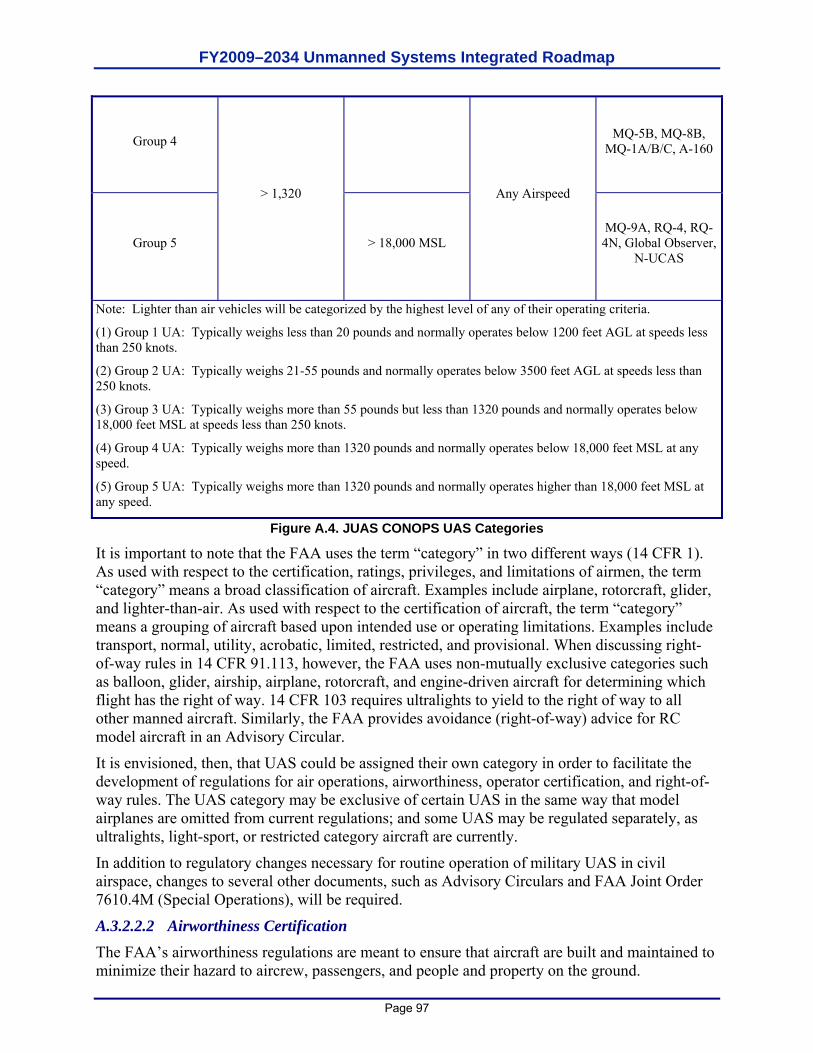
FY2009–2034 Unmanned Systems Integrated Roadmap
Page 97
Group 4 MQ-5B, MQ-8B, MQ-1A/B/C, A-160
Group 5
> 1,320
> 18,000 MSL
Any Airspeed
MQ-9A, RQ-4, RQ-4N, Global Observer,
N-UCAS
Note: Lighter than air vehicles will be categorized by the highest level of any of their operating criteria.
(1) Group 1 UA: Typically weighs less than 20 pounds and normally operates below 1200 feet AGL at speeds less than 250 knots.
(2) Group 2 UA: Typically weighs 21-55 pounds and normally operates below 3500 feet AGL at speeds less than 250 knots.
(3) Group 3 UA: Typically weighs more than 55 pounds but less than 1320 pounds and normally operates below 18,000 feet MSL at speeds less than 250 knots.
(4) Group 4 UA: Typically weighs more than 1320 pounds and normally operates below 18,000 feet MSL at any speed.
(5) Group 5 UA: Typically weighs more than 1320 pounds and normally operates higher than 18,000 feet MSL at any speed.
Figure A.4. JUAS CONOPS UAS Categories
It is important to note that the FAA uses the term “category” in two different ways (14 CFR 1). As used with respect to the certification, ratings, privileges, and limitations of airmen, the term “category” means a broad classification of aircraft. Examples include airplane, rotorcraft, glider, and lighter-than-air. As used with respect to the certification of aircraft, the term “category” means a grouping of aircraft based upon intended use or operating limitations. Examples include transport, normal, utility, acrobatic, limited, restricted, and provisional. When discussing right-of-way rules in 14 CFR 91.113, however, the FAA uses non-mutually exclusive categories such as balloon, glider, airship, airplane, rotorcraft, and engine-driven aircraft for determining which flight has the right of way. 14 CFR 103 requires ultralights to yield to the right of way to all other manned aircraft. Similarly, the FAA provides avoidance (right-of-way) advice for RC model aircraft in an Advisory Circular.
It is envisioned, then, that UAS could be assigned their own category in order to facilitate the development of regulations for air operations, airworthiness, operator certification, and right-of-way rules. The UAS category may be exclusive of certain UAS in the same way that model airplanes are omitted from current regulations; and some UAS may be regulated separately, as ultralights, light-sport, or restricted category aircraft are currently.
In addition to regulatory changes necessary for routine operation of military UAS in civil airspace, changes to several other documents, such as Advisory Circulars and FAA Joint Order 7610.4M (Special Operations), will be required.
A.3.2.2.2 Airworthiness Certification The FAA’s airworthiness regulations are meant to ensure that aircraft are built and maintained to minimize their hazard to aircrew, passengers, and people and property on the ground.
FY2009–2034 Unmanned Systems Integrated Roadmap
Page 98
Airworthiness is concerned with the material and construction integrity of the individual aircraft and the prevention of the aircraft’s coming apart in mid-air and/or causing damage to persons or property on the ground. Over the 19-year period from 1982 to 2000, an annual average of 2.2 percent of all aviation fatalities involved people being hit by parts falling off aircraft. A UAS that must be available for unrestricted operations worldwide (e.g., Global Hawk) in most classes of airspace compels serious consideration for the safety of people on the ground. The operational requirements for UAS operation in civil airspace means flight over populated areas must not raise concerns based on overall levels of airworthiness; therefore, UAS standards cannot vary widely from those for manned aircraft without raising public and regulatory concern.
FAA regulations do not require “public aircraft” (Government-owned or -operated) to be certified airworthy to FAA standards. Most nonmilitary public aircraft are versions of aircraft previously certified for commercial or private use; however, the only public aircraft not related to FAA certification standards in some way are almost always military aircraft. These aircraft are certified through the military’s internal airworthiness certification/flight release process. A Tri Service memorandum of agreement describes the responsibilities and actions associated with mutual acceptance of airworthiness certifications for manned aircraft and UAS within the same certified design configuration, envelope, parameters, and usage limits certified by the originating Military Department.
Similarly to manned military aircraft, unmanned military aircraft will also be subject to the airworthiness certification/flight release process. The Global Hawk has completed this process and has been granted an airworthiness certificate.
A.3.2.2.3 Crew Qualifications The FAA’s qualification standards (14 CFR 61, 63, 65, and 67) are meant to ensure the competency of aircrew and aircraft maintainers. As in the case of airworthiness certification, these CFR parts do not pertain to military personnel who are certified in a similar, parallel process. DoD and FAA have signed a memorandum of agreement through which DoD agrees to meet or exceed civil training standards, and the FAA agrees to accept military-rated pilots into the NAS. These factors indicate that a certain minimum knowledge standard is required of all pilots-in-command in order to operate aircraft in the NAS. In order to meet the intent of “do no harm,” training for Cat III aircraft would include, but not be limited to, regulations, airspace clearances and restrictions, aircraft flight rules, air traffic communications, aircraft sequencing and prioritization, takeoff and landing procedures for combined manned and unmanned operations, go-around and abort procedures, flight planning and filing (including in-flight filing), flight and communications procedures for lost link, weather reporting and avoidance, ground operations for combined manned and unmanned operations, flight speed and altitude restrictions, and, when applicable, weapons carriage procedures (including hung ordinance flight restrictions).
Under the international doctrine for public aircraft, the FAA does not have to agree with DoD training or accept military ratings; the Military Departments are entitled to make these judgments independently. Each Military Department identifies what and how it will operate and create the training programs necessary to safely accomplish its missions. Some of the UAS-related training is a fundamental shift away from the skills needed to fly a manned aircraft (e.g., ground-based visual landing). These differences can relate to the means of landing: visual remote, aided visual, or fully autonomous. They may also relate to different interface designs for the UAS functions or the level of control needed to exercise authority over an aircraft based on its autonomous capability. As a result, the Military Departments will have minimum standards for knowledge
FY2009–2034 Unmanned Systems Integrated Roadmap
Page 99
skills required of UAS operators operating in the NAS; this minimum standard may differ for given classes of UAS. UAS operators will be expected to conform to these requirements.
A.3.2.3 “See and Avoid” (S&A) Principle A key requirement for routine access to the NAS is UAS compliance with 14 CFR 91.113, “Right-of-Way Rules: Except Water Operations.” This section contains the phrase “sense and avoid” and is the primary restriction to normal operations of UAS. The intent of “sense and avoid” is for pilots to use their sensors (eyes) and other tools to find and maintain situational awareness of other traffic and to yield the right-of-way, in accordance with the rules, when there is a traffic conflict. Since the purpose of this regulation is to avoid mid-air collisions, this should be the focus of technological efforts to address the issue as it relates to UAS rather than trying to mimic and/or duplicate human vision. In June 2003, USAF’s Air Combat Command (ACC) sponsored a joint working group to establish and quantify an S&A system capability for submission to the FAA. Their white paper, “See and Avoid Requirement for Remotely Operated Aircraft,” was released in June 2004.
Relying simply on human vision results in mid-air collisions accounting for an average of 0.8 percent of all mishaps and 2.4 percent of all aviation fatalities incurring annually (based on the 3-year average from 1998 to 2000). Meaningful S&A performance must alert the UAS operator to local air traffic at ranges sufficient for reaction time and avoidance actions by safe margins. Furthermore, UAS operations BLOS may require an automated S&A system due to potential communications latencies or failures.
The FAA does not provide a quantitative definition of S&A, largely due to the number of combinations of pilot vision, collision vectors, sky background, and aircraft paint schemes involved in seeing oncoming traffic. Having a sufficient field of regard for a UAS S&A system, however, is fundamental to meeting the goal of assured air traffic separation.
Although an elusive issue, one fact is apparent. The challenge with the S&A issue is both a capability constraint and a regulatory one. Given the discussions in this and other analyses, a possible definition for S&A systems emerges: S&A is the onboard, self-contained ability to
Detect traffic that may be a conflict, Evaluate flight paths, Determine traffic right of way, and Maneuver well clear according to the rules in Part 91.113.
The key to providing the “equivalent level of safety” required by FAA Order 7610.4M, “Special Operations,” Chapter 12, Section 9, “UAS Operations in the NAS,” is the provision of some comparable means of S&A to that provided by pilots on board manned aircraft. The purpose of S&A is to avoid mid-air collisions, and this should be the focus of technological efforts to automate this capability, rather than trying to mechanize human vision.
From a technical perspective, the S&A capability can be divided into the detection of oncoming traffic and the execution of a maneuver to avoid a mid-air collision. The detection aspect can be further subdivided into passive or active techniques applicable in cooperative or non-cooperative traffic environments.
The active cooperative scenario involves an interrogator monitoring a sector ahead of the UAS to detect oncoming traffic by interrogating the transponder on the other aircraft. Its advantages are that it provides both range and bearing to the traffic and can function in both visual and instrument meteorological conditions (i.e., Visual Meteorological Conditions [VMC] and
FY2009–2034 Unmanned Systems Integrated Roadmap
Page 100
Instrument Meteorological Conditions [IMC]). Its disadvantages are its relative cost. Current systems available in this category include the various TCASs.
The active non-cooperative scenario relies on a radar- or laser-like sensor scanning a sector ahead of the UAS to detect all traffic, whether transponder-equipped or not. The returned signal provides range, bearing, and closure rate and allows prioritization of oncoming traffic for avoidance, in either VMC or IMC. Its potential drawbacks are its relative cost, the bandwidth requirement to route its imagery (for non-autonomous systems), and its weight. An example of an active, non-cooperative system that is currently available is a combined microwave radar and infrared sensor originally developed to enable helicopters to avoid power lines.
The passive cooperative scenario, like the active cooperative one, relies on everyone having a transponder, but with everyone’s transponder broadcasting position, altitude, and velocity data. Its advantages are its lower relative cost (no onboard interrogator required to activate transponders) and its ability to provide S&A information in both VMC and IMC. Its disadvantage is its dependence on all traffic carrying and continuously operating transponders. In this scenario, UAS should have the capability to change transponder settings while in flight.
The passive non-cooperative scenario is the most demanding one. It is also the most analogous to the human eye. An S&A system in this scenario relies on a sensor to detect and provide azimuth and elevation to the oncoming traffic. Its advantages are its moderate relative cost and ability to detect non-transponder-equipped traffic. Its disadvantages are its lack of direct range or closure rate information, potentially high bandwidth requirement (if not autonomous), and its probable inability to penetrate weather. The gimbaled EO/IR sensors currently carried by reconnaissance UAS are examples of such systems; however, if they are looking at the ground for reconnaissance, then they are not available to perform S&A. An emerging approach that would negate the high bandwidth requirement of any active system is optical flow technology, which reports only when it detects an object showing a lack of movement against the sky, instead of sending a continuous video stream to the ground controller. Imagery from one or more inexpensive optical sensors on the UAS is continuously compared to the last image by an onboard processor to detect minute changes in pixels, indicating traffic of potential interest. Only when such objects are detected is their bearing relayed to the ground.
Once the “detect and sense” portion of S&A is satisfied, the UAS must use this information to execute an avoidance maneuver. The latency between seeing and avoiding for the pilot of a manned aircraft ranges from 10 to 12.5 seconds according to FAA and DoD studies. If relying on a ground operator to S&A, the UAS incurs the same human latency, but adds the latency of the data link bringing the image to the ground for a decision and the avoidance command back to the UAS. This added latency can range from less than a second for LOS links to more time for satellite links.
An alternative is to empower the UAS to autonomously decide whether and which way to react to avoid a collision once it detects oncoming traffic, thereby removing the latency imposed by data links. This approach has been considered for implementation on TCAS II-equipped manned aircraft since TCAS II already recommends a vertical direction to the pilot, but simulations have found the automated maneuver worsens the situation in a fraction of the scenarios. For this reason, the FAA has not certified automated collision avoidance algorithms based on TCAS resolution advisories; doing so would set a significant precedent for UAS S&A capabilities.
The long-term FAA plan is “to move away from infrastructure-based systems towards a more autonomous, aircraft-based system” for collision avoidance. Installation of TCAS is increasing
FY2009–2034 Unmanned Systems Integrated Roadmap
Page 101
across the aviation community, and TCAS functionality supports increased operator autonomy. Research and testing of Automatic Dependent Surveillance-Broadcast (ADS-B) may afford an even greater capability and affirms the intent of the aviation community to support and continue down this path. Such equipment complements basic S&A, adds to the situational awareness, and helps provide separation from close traffic in all meteorological conditions.
A.3.3 Command, Control, Communications A.3.3.1 Data Link Security In general, there are two main areas of concern when considering link security: inadvertent or hostile interference of the uplink and downlink. The forward (“up”) link controls the activities of the platform itself and the payload hardware. This command and control link requires a sufficient degree of security to ensure that only authorized agents have access to the control mechanisms of the platform. The return (“down”) link transmits critical data from the platform payload to the Warfighter or analyst on the ground or in the air. System health and status information must also be delivered to the GCS or UAS operator without compromise. Effective frequency spectrum allocation and management are key to reducing inadvertent interference of the data links.
A.3.3.2 Redundant/Independent Navigation The air navigation environment is changing, in part, because of the demands of increased traffic flow. Allowances for deviation from intended flight paths are being reduced. This provides another means for increasing air traffic capacity as airways and standard departures and approaches can be constructed with less separation. As tolerances for navigational deviation decrease, the need to precisely maintain course grows. All aircraft must ensure they have robust navigational means. Historically, this robustness has been achieved by installation of redundant navigational systems. The need for dependable, precise navigation reinforces the redundancy requirements.
While navigation accuracy and reliability pertain to military operations and traffic management, current systems are achieving the necessary standard without redundancy and without reliance on ground-based navigation aids. The Federal Radionavigation Plan, signed January 2006, establishes the following national policies:
Properly certified GPS is approved as a supplemental system for domestic en route and terminal navigation, and for nonprecision approach and landing operations.
The FAA’s phase-down plan for ground-based navigation aid systems (NAVAIDS) retains at least a minimum operational network of ground-based NAVAIDS for the foreseeable future.
Sufficient ground-based NAVAIDS will be maintained to provide the FAA and the airspace users with a safe recovery and sustained operations capability in the event of a disruption in satellite navigation service.
These policies apply, as a minimum, to all aircraft flying in civil airspace. With GPS, the prospect for relief of some redundancy requirements in manned aviation may be an option in the future. However, UAS have a diminished prospect for relief since, unlike manned aircraft, a UAS without communication links cannot readily fall back on dead reckoning, contact navigation, and map reading in the same sense that a manned aircraft can.
A.3.3.3 Autonomy Advances in computer and communications technologies have enabled the development of autonomous unmanned systems. With the increase in computational power available,
FY2009–2034 Unmanned Systems Integrated Roadmap
Page 102
developmental UAS are able to achieve much more sophisticated subsystem, guidance, navigation and control, sensor, and communications autonomy than previous systems. For example, Global Hawk’s airborne systems are designed to identify, isolate, and compensate for a wide range of possible system/subsystem failures and autonomously take actions to ensure system safety. Preprogrammed decision trees are built to address each possible failure during each part of the mission.
One of the most difficult aspects of high levels of autonomy is ensuring that all elements remain synchronized. A key accomplishment will be to verify that: 1) all messages are received; 2) all aircraft have correctly interpreted the messages; and 3) the entire squadron has a single set of mission plans to execute.
A.3.3.4 Lost Link In the event of lost C2 links, military UAS are typically programmed to climb to a predefined altitude to attempt to reestablish contact; this “lost link profile” may not be appropriate for operations in the NAS. If contact is not reestablished in a given time, the UAS can be preprogrammed to retrace its outbound route home, fly direct to home, or continue its mission. With an irreversible loss of the C2 data link, however, there is usually no procedure for a communications-out recovery (Global Hawk does have this capability using differential GPS and pre-programmed divert airfields). Examination of a lost C2 link scenario illustrates that this communications issue can become a critical UAS failure mode. At present, DoD UAS platforms have a multitude of lost link procedures based on service requirements and acquisition strategies. In order for DoD UAS access to gain more routine, seamless access to the NAS, the DoD needs to develop standard lost link procedures for systems requiring routine access to the NAS. This will provide the Federal Aviation Administration with predictable, consistent lost link procedures when working with DoD UAS.
No Radio (NORDO) requirements are well documented in 14 CFR 91.185. Remarkably, most lost C2 link situations bear a striking resemblance to NORDO, and UAS would enhance their predictability by autonomously following the guidance. The one exception to this case is the VFR conditions clause. UAS, even with an autonomous S&A system, would enhance overall safety by continuing to fly IFR. Should normal ATC-voice communications fail, the FAA also has the capability to patch airspace users through to the controlling ATC authority by phone at any time.
A.3.4 Future Environment The migration of the NAS from ground-based traffic control to airborne traffic management, scheduled to occur over the next decade, will have significant implications for UAS. S&A will become an integrated, automated part of routine position reporting and navigation functions by relying on a combination of ADS-B and GPS. In effect, it will create a virtual bubble of airspace around each aircraft so that when bubbles contact, avoidance is initiated. All aircraft will be required to be equipped to the same level, making the unmanned or manned status of an aircraft transparent to both flyers and to the FAA.
Finally, the pejorative perception that UAS are by nature more dangerous than manned aircraft needs to be countered by recognizing that UAS can provide an equivalent level of safety to that of manned aircraft and possess the following inherent attributes that contribute to flying safety:
Many manned aircraft mishaps occur during the takeoff and landing phases of flight, when human decisions and control inputs are substantial factors. Robotic aircraft are not
FY2009–2034 Unmanned Systems Integrated Roadmap
Page 103
programmed to take chances; either preprogrammed conditions are met or the system goes around. This will likely reduce the incidence of mishaps during these phases of flight.
Since human support systems are not carried, mishaps from failed life support systems (e.g., Payne Stewart, Helios Airways 522) will not occur.
An automated takeoff and landing capability reduces the need for pattern work and results in reduced exposure to mishaps, particularly in the area surrounding main operating bases.
UAS control stations can access resources not available in the traditional cockpit and thus increase the operator’s situational awareness.
A greater percentage of UAS operator training can be performed through simulation given the nature of GCSs. Using simulations reduces the need to actually fly the aircraft and the related exposure to mishaps.
A.3.5 Department of Defense (DoD) Organizations with Roles in Unmanned Aircraft System (UAS) Airspace Integration
As discussed, access to the NAS is currently attained primarily through the COA process, which relies on a combination of procedures and observers to provide the ELOS for UAS. Both regulatory and technical issues need to be addressed to attain UAS integration. The organizations within the DoD that are addressing these issues and are related to current and future operations include OSD Oversight and Policy, the Joint Staff chartered organizations, and the military departments’ chartered organizations.
A.3.5.1 OUSD Oversight and Policy The Office of the Under Secretary of Defense (OUSD) (Acquisition Technology and Logistics [AT&L]) established the UAS PTF in October 2001 to address the need for an integrated Defense-wide initiative for UAS planning and execution. The UAS PTF provides oversight on all DoD UAS acquisition programs.
DoDD 5030.19 directs the Assistant Secretary of Defense (Networks and Information Integration) (ASD(NII)) to chair the DoD PBFA. The PBFA shall advise and assist the ASD(NII) on ATC, airspace management, NAS matters, joint systems acquisition, and aviation-related international affairs. Supporting the PBFA are the PBFA Working Group and the UAS Subgroup.
The ASD (Homeland Defense [HD]) is the Department’s interface with DHS. It has been directed to develop a comprehensive policy document on domestic use of UAS.
A.3.5.2 Joint Staff Chartered Organizations The JROC chartered two organizations to improve UAS interoperability and operational effectiveness of UAS:
The former JUAS Material Review Board (MRB), disestablished in November 2007, to provide a UAS forum to identify or resolve requirements and corresponding materiel issues (July 5, 2005), and
The JUAS Center of Excellence (COE), to pursue solutions to optimize UAS capabilities and utilization (including concepts of operation).
The JUAS MRB was tasked to determine if the current DoD organizations working the UAS airspace integration issue were adequately resourced, both in funding and personnel. The JUAS
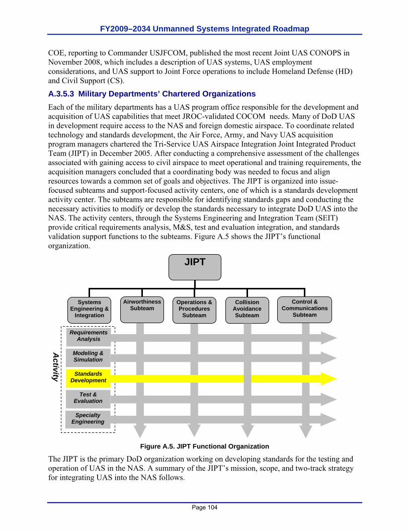
FY2009–2034 Unmanned Systems Integrated Roadmap
Page 104
COE, reporting to Commander USJFCOM, published the most recent Joint UAS CONOPS in November 2008, which includes a description of UAS systems, UAS employment considerations, and UAS support to Joint Force operations to include Homeland Defense (HD) and Civil Support (CS).
A.3.5.3 Military Departments’ Chartered Organizations Each of the military departments has a UAS program office responsible for the development and acquisition of UAS capabilities that meet JROC-validated COCOM needs. Many of DoD UAS in development require access to the NAS and foreign domestic airspace. To coordinate related technology and standards development, the Air Force, Army, and Navy UAS acquisition program managers chartered the Tri-Service UAS Airspace Integration Joint Integrated Product Team (JIPT) in December 2005. After conducting a comprehensive assessment of the challenges associated with gaining access to civil airspace to meet operational and training requirements, the acquisition managers concluded that a coordinating body was needed to focus and align resources towards a common set of goals and objectives. The JIPT is organized into issue-focused subteams and support-focused activity centers, one of which is a standards development activity center. The subteams are responsible for identifying standards gaps and conducting the necessary activities to modify or develop the standards necessary to integrate DoD UAS into the NAS. The activity centers, through the Systems Engineering and Integration Team (SEIT) provide critical requirements analysis, M&S, test and evaluation integration, and standards validation support functions to the subteams. Figure A.5 shows the JIPT’s functional organization.
Figure A.5. JIPT Functional Organization
The JIPT is the primary DoD organization working on developing standards for the testing and operation of UAS in the NAS. A summary of the JIPT’s mission, scope, and two-track strategy for integrating UAS into the NAS follows.
JIPT
CollisionAvoidanceSubteam
Airworthiness Subteam
Operations & Procedures
Subteam
Control & Communications
Subteam
Systems Engineering &
Integration
Requirements Analysis
Modeling & Simulation
Test & Evaluation
Specialty Engineering
Standards Development
Activity
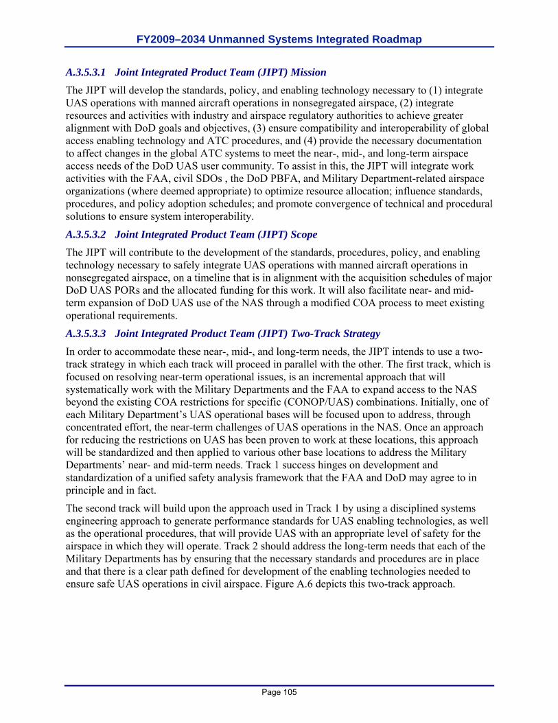
FY2009–2034 Unmanned Systems Integrated Roadmap
Page 105
A.3.5.3.1 Joint Integrated Product Team (JIPT) Mission The JIPT will develop the standards, policy, and enabling technology necessary to (1) integrate UAS operations with manned aircraft operations in nonsegregated airspace, (2) integrate resources and activities with industry and airspace regulatory authorities to achieve greater alignment with DoD goals and objectives, (3) ensure compatibility and interoperability of global access enabling technology and ATC procedures, and (4) provide the necessary documentation to affect changes in the global ATC systems to meet the near-, mid-, and long-term airspace access needs of the DoD UAS user community. To assist in this, the JIPT will integrate work activities with the FAA, civil SDOs , the DoD PBFA, and Military Department-related airspace organizations (where deemed appropriate) to optimize resource allocation; influence standards, procedures, and policy adoption schedules; and promote convergence of technical and procedural solutions to ensure system interoperability.
A.3.5.3.2 Joint Integrated Product Team (JIPT) Scope The JIPT will contribute to the development of the standards, procedures, policy, and enabling technology necessary to safely integrate UAS operations with manned aircraft operations in nonsegregated airspace, on a timeline that is in alignment with the acquisition schedules of major DoD UAS PORs and the allocated funding for this work. It will also facilitate near- and mid-term expansion of DoD UAS use of the NAS through a modified COA process to meet existing operational requirements.
A.3.5.3.3 Joint Integrated Product Team (JIPT) Two-Track Strategy In order to accommodate these near-, mid-, and long-term needs, the JIPT intends to use a two-track strategy in which each track will proceed in parallel with the other. The first track, which is focused on resolving near-term operational issues, is an incremental approach that will systematically work with the Military Departments and the FAA to expand access to the NAS beyond the existing COA restrictions for specific (CONOP/UAS) combinations. Initially, one of each Military Department’s UAS operational bases will be focused upon to address, through concentrated effort, the near-term challenges of UAS operations in the NAS. Once an approach for reducing the restrictions on UAS has been proven to work at these locations, this approach will be standardized and then applied to various other base locations to address the Military Departments’ near- and mid-term needs. Track 1 success hinges on development and standardization of a unified safety analysis framework that the FAA and DoD may agree to in principle and in fact.
The second track will build upon the approach used in Track 1 by using a disciplined systems engineering approach to generate performance standards for UAS enabling technologies, as well as the operational procedures, that will provide UAS with an appropriate level of safety for the airspace in which they will operate. Track 2 should address the long-term needs that each of the Military Departments has by ensuring that the necessary standards and procedures are in place and that there is a clear path defined for development of the enabling technologies needed to ensure safe UAS operations in civil airspace. Figure A.6 depicts this two-track approach.
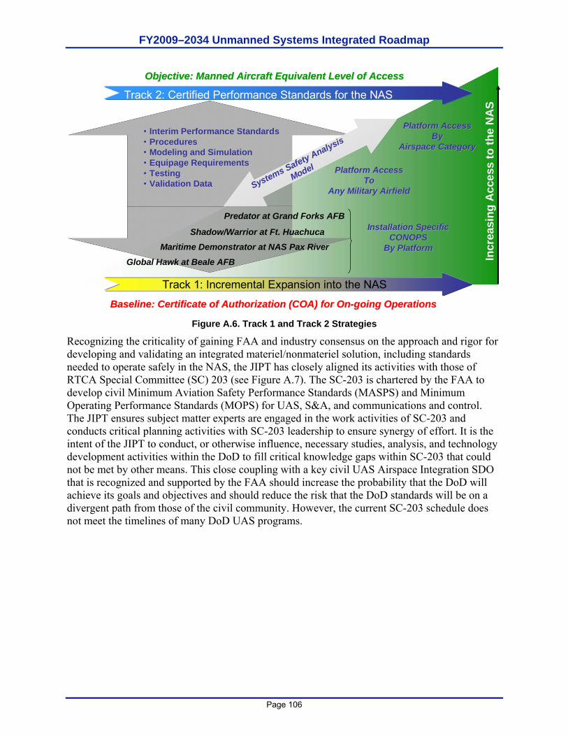
FY2009–2034 Unmanned Systems Integrated Roadmap
Page 106
Figure A.6. Track 1 and Track 2 Strategies
Recognizing the criticality of gaining FAA and industry consensus on the approach and rigor for developing and validating an integrated materiel/nonmateriel solution, including standards needed to operate safely in the NAS, the JIPT has closely aligned its activities with those of RTCA Special Committee (SC) 203 (see Figure A.7). The SC-203 is chartered by the FAA to develop civil Minimum Aviation Safety Performance Standards (MASPS) and Minimum Operating Performance Standards (MOPS) for UAS, S&A, and communications and control. The JIPT ensures subject matter experts are engaged in the work activities of SC-203 and conducts critical planning activities with SC-203 leadership to ensure synergy of effort. It is the intent of the JIPT to conduct, or otherwise influence, necessary studies, analysis, and technology development activities within the DoD to fill critical knowledge gaps within SC-203 that could not be met by other means. This close coupling with a key civil UAS Airspace Integration SDO that is recognized and supported by the FAA should increase the probability that the DoD will achieve its goals and objectives and should reduce the risk that the DoD standards will be on a divergent path from those of the civil community. However, the current SC-203 schedule does not meet the timelines of many DoD UAS programs.
Track 2: Certified Performance Standards for the NAS
Track 1: Incremental Expansion into the NAS
Incr
easi
ng A
cces
s to
the
NA
S
Global Hawk at Beale AFB
Shadow/Warrior at Ft. HuachucaMaritime Demonstrator at NAS Pax River
Predator at Grand Forks AFB
Baseline: Certificate of Authorization (COA) for OnBaseline: Certificate of Authorization (COA) for On--going Operationsgoing Operations
Objective: Manned Aircraft Equivalent Level of Access Objective: Manned Aircraft Equivalent Level of Access
Installation SpecificInstallation SpecificCONOPSCONOPS
By PlatformBy Platform
Platform AccessPlatform AccessToTo
Any Military AirfieldAny Military Airfield
Platform AccessPlatform AccessByBy
Airspace CategoryAirspace Category
•• Interim Performance StandardsInterim Performance Standards•• ProceduresProcedures•• Modeling and SimulationModeling and Simulation•• Equipage RequirementsEquipage Requirements•• TestingTesting•• Validation Data Validation Data Systems Safety Analysis
Model
FY2009–2034 Unmanned Systems Integrated Roadmap
Page 107
Track 1 (DoD/FAA)• Programmatic Framework• Systems Safety Framework• Process Elements
– Local/Regional CONEMP– System Characterization
• UAS• Airspace• Air Traffic Management
– System Analysis• Safety• Operational
– Risks/ Impacts– Restrictions/Limitations– Risk Mitigation
• Technical Feasibility• Cost• Schedule• Decision (Yes/No)
– Data Collection• Safety/Operations Feedback Loop
Track 2 SC-203• Standards Development Phase
– CONOPS– Validated Operational Requirements– Gap Analysis– Functional Requirements– Initial Performance Standards
• Subject Matter Experts• JCTD PHASE I
• Standards Validation Phase– M&S– T&E– Analysis– JCTD PHASE II (Standards Validation)
• Policy/Regulatory Recommendations
Information – Data
Near Near
MidMid
LongLong
VTUAVVTUAV BAMSBAMS NN--UCASUCASWarriorWarrior
PBFAPBFA FAAFAA
Figure A.7. Track 1, Track 2, and SC-203
A.3.5.3.3.1 Track 1 Definition
The objective of Track 1 is to incrementally expand UAS access to the NAS in the near- to mid term to meet current and/or emerging operational requirements. Track 1 will focus on installation-specific CONOP by UAS platform. This track will not seek to change national level policy. The priority for working each installation-specific UAS CONOP will be determined by the individual Military Departments and must comply with the UAS-related standards including system hardware and operators’ qualifications/currency requirements. One of the key activities within Track 1 will be to perform a standardized safety analysis that will seek access to regional airspace through an expanded COA. Track 1 will focus on providing cost-effective, operationally useful expansion of UAS access to the NAS that is targeted to specific operational needs of the Military Departments. The JIPT will employ both procedural and/or technical solutions to mitigate risk and to accomplish this objective.
To facilitate a standardized Track 1 approach, the JIPT will work with the FAA’s Unmanned Aircraft Program Office to establish a mutually agreeable process in which to evaluate DoD requests for expanded airspace access. Based on this integrated approach with the FAA, the JIPT will provide the requesting Military Department with the appropriate information to conduct the safety study and submit a complete package to the FAA for final approval. Once a sufficient body of data has been collected, the JIPT will expand the Track 1 efforts beyond a single installation with a specific UAS CONOP and move toward an integrated approach for increased UAS access. This will be accomplished through additional analysis and data collected from ongoing operations to substantiate the ability to safely operate a given UAS outside DoD-controlled airfields, or alternatively, multiple UAS platforms out of a single DoD-controlled airfield. The compilation of the individual installation efforts into an integrated NAS-level analysis should support the performance standards development effort in Track 2.
FY2009–2034 Unmanned Systems Integrated Roadmap
Page 108
The incremental approach to airspace integration in Track 1 should result in two key outcomes:
DoD will have an avenue to meet near- to mid-term operational needs to operate in the NAS, and
It will provide a forum for other airspace users, regulators, and the general public to become comfortable with the level of safety demonstrated by DoD UAS operations.
A.3.5.3.3.2 Track 2 Definition
The objective of Track 2 is to develop the performance standards for enabling DoD UAS operations and to recommend the necessary changes to existing FAA policy and/or CFR required to routinely operate UAS within the NAS. Track 2, therefore, will at a minimum attempt to establish and validate the standards needed to provide UAS with a level of safety equivalent to that of manned aircraft. To arrive at the needed performance standards, the JIPT will integrate the data collected from flight operations in Track 1 with an initial set of performance standards. These standards will be developed in coordination with the appropriate organizations needed to concur on an initial set of standards. The JIPT will then proceed with a detailed assessment of these initial performance standards through a rigorous M&S analysis effort. The JIPT will work, in coordination with the FAA’s Unmanned Aircraft Program Office through the DoD PBFA and the Military Departments’ airspace functional organizations (i.e. Air Force Flight Standards Agency, U.S. Army Aeronautical Service Agency, the Chief of Naval Operations (Code N88F), and Headquarters, Marine Corps [HQMC] Aviation [APC]) to ensure that the M&S approach taken by the JIPT has the degree of rigor and specificity needed by the FAA for high-confidence results. The JIPT’s M&S activity will be open to FAA and FAA-designated agents to advise on the degree of rigor for high-confidence results. As these standards are developed and validated, the JIPT will provide data and results to the SDOs used by the FAA for developing certified standards.
Once initial results from the M&S activity are produced, an initial evaluation of the overall UAS performance can be determined, and appropriate modifications can be made to the performance standards until the appropriate level of safety is achieved for the UAS. These performance standards will then be validated through an appropriate test and evaluation phase that will validate the M&S assumptions and performance characteristics and provide the needed real-world data to substantiate and validate the standards themselves. These validated performance standards will then be provided to the appropriate SDOs for developing certified regulatory guidance for the FAA. In addition, the JIPT intends to coordinate this work (technology development, acquisition, demonstrations, flight test) through the individual Military Departments’ UAS program offices, which will be responsible for meeting the finalized set of standards and procedures. The JIPT will then refine the Track 1 analysis and data collection activities to improve the fidelity of the validation process. These refinements will be made in close coordination with the FAA’s Unmanned Aircraft Program Office to continuously align our process with their analysis requirements. A.3.5.3.3.3 Unmanned Aircraft System (UAS) Airspace Integration Roadmap
Track 1 and Track 2 strategy implementation is outlined in the proposed UAS Airspace Integration Roadmap (see Figure A.8), which is currently being socialized within the broader DoD stakeholder community. The degree to which this plan will be successful depends upon the following:

FY2009–2034 Unmanned Systems Integrated Roadmap
Page 109
The key stakeholders organizations and communities must reach consensus on a common path forward, and
The effort must be prioritized in terms of expertise applied to the effort along with the appropriate level of funding to execute on the timeline provided.

FY2009–2034 Unmanned Systems Integrated Roadmap
Page 110
This page is intentionally left blank.
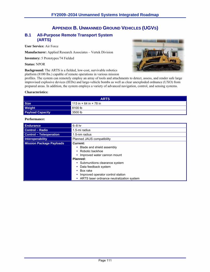
FY2009–2034 Unmanned Systems Integrated Roadmap
Page 111
APPENDIX B. UNMANNED GROUND VEHICLES (UGVS) B.1 All-Purpose Remote Transport System
(ARTS) User Service: Air Force
Manufacturer: Applied Research Associates – Vertek Division
Inventory: 5 Prototypes/74 Fielded
Status: NPOR
Background: The ARTS is a fielded, low-cost, survivable robotics platform (8100 lbs.) capable of remote operations in various mission profiles. The system can remotely employ an array of tools and attachments to detect, assess, and render safe large improvised explosive devices (IEDs) and large-vehicle bombs as well as clear unexploded ordnance (UXO) from prepared areas. In addition, the system employs a variety of advanced navigation, control, and sensing systems.
Characteristics:
ARTS Size 113 in × 64 in × 78 in Weight 8100 lb Payload Capacity 3500 lb
Performance:
Endurance 6–8 hr Control – Radio 1.5-mi radius Control – Teleoperation 1.5-nm radius Interoperability Planned JAUS compatibility Mission Package Payloads Current:
Blade and shield assembly Robotic backhoe Improved water cannon mount
Planned: Submunitions clearance system Data feedback system Box rake Improved operator control station ARTS laser ordnance neutralization system
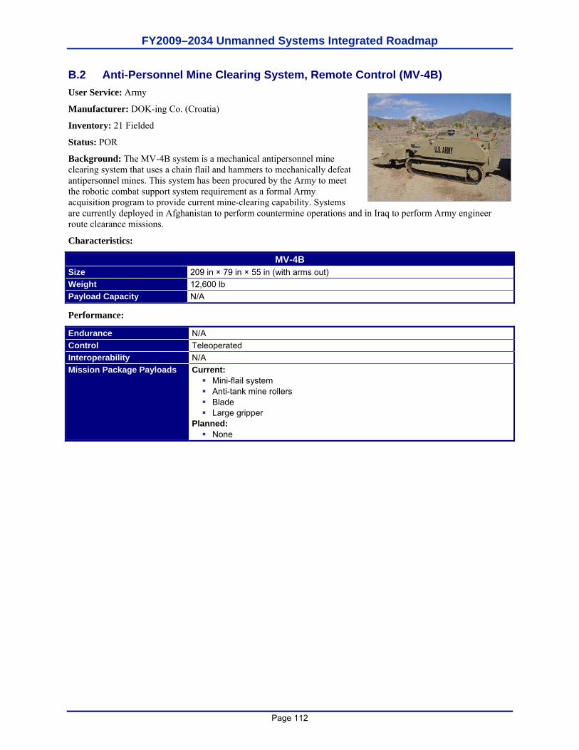
FY2009–2034 Unmanned Systems Integrated Roadmap
Page 112
B.2 Anti-Personnel Mine Clearing System, Remote Control (MV-4B) User Service: Army
Manufacturer: DOK-ing Co. (Croatia)
Inventory: 21 Fielded
Status: POR
Background: The MV-4B system is a mechanical antipersonnel mine clearing system that uses a chain flail and hammers to mechanically defeat antipersonnel mines. This system has been procured by the Army to meet the robotic combat support system requirement as a formal Army acquisition program to provide current mine-clearing capability. Systems are currently deployed in Afghanistan to perform countermine operations and in Iraq to perform Army engineer route clearance missions.
Characteristics:
MV-4B Size 209 in × 79 in × 55 in (with arms out) Weight 12,600 lb Payload Capacity N/A
Performance:
Endurance N/A Control Teleoperated Interoperability N/A Mission Package Payloads Current:
Mini-flail system Anti-tank mine rollers Blade Large gripper
Planned: None
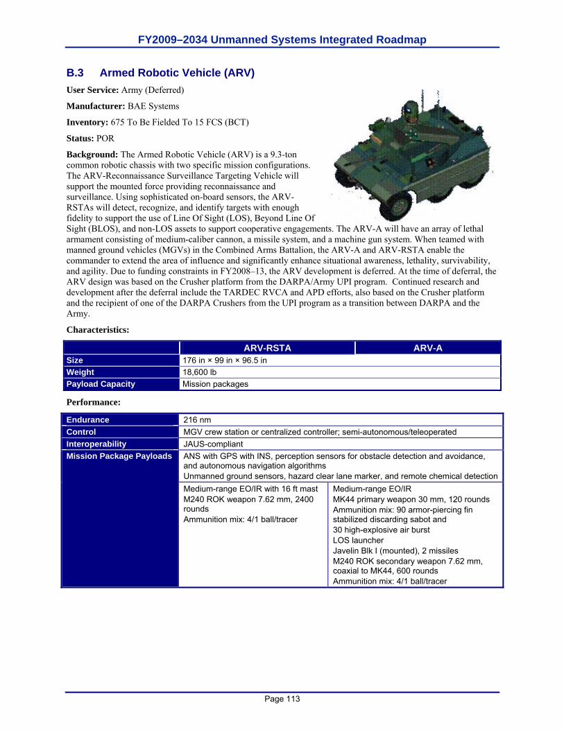
FY2009–2034 Unmanned Systems Integrated Roadmap
Page 113
B.3 Armed Robotic Vehicle (ARV) User Service: Army (Deferred)
Manufacturer: BAE Systems
Inventory: 675 To Be Fielded To 15 FCS (BCT)
Status: POR
Background: The Armed Robotic Vehicle (ARV) is a 9.3-ton common robotic chassis with two specific mission configurations. The ARV-Reconnaissance Surveillance Targeting Vehicle will support the mounted force providing reconnaissance and surveillance. Using sophisticated on-board sensors, the ARV-RSTAs will detect, recognize, and identify targets with enough fidelity to support the use of Line Of Sight (LOS), Beyond Line Of Sight (BLOS), and non-LOS assets to support cooperative engagements. The ARV-A will have an array of lethal armament consisting of medium-caliber cannon, a missile system, and a machine gun system. When teamed with manned ground vehicles (MGVs) in the Combined Arms Battalion, the ARV-A and ARV-RSTA enable the commander to extend the area of influence and significantly enhance situational awareness, lethality, survivability, and agility. Due to funding constraints in FY2008–13, the ARV development is deferred. At the time of deferral, the ARV design was based on the Crusher platform from the DARPA/Army UPI program. Continued research and development after the deferral include the TARDEC RVCA and APD efforts, also based on the Crusher platform and the recipient of one of the DARPA Crushers from the UPI program as a transition between DARPA and the Army.
Characteristics:
ARV-RSTA ARV-A Size 176 in × 99 in × 96.5 in Weight 18,600 lb Payload Capacity Mission packages
Performance:
Endurance 216 nm Control MGV crew station or centralized controller; semi-autonomous/teleoperated Interoperability JAUS-compliant
ANS with GPS with INS, perception sensors for obstacle detection and avoidance, and autonomous navigation algorithms Unmanned ground sensors, hazard clear lane marker, and remote chemical detection
Mission Package Payloads
Medium-range EO/IR with 16 ft mast M240 ROK weapon 7.62 mm, 2400 rounds Ammunition mix: 4/1 ball/tracer
Medium-range EO/IR MK44 primary weapon 30 mm, 120 rounds Ammunition mix: 90 armor-piercing fin stabilized discarding sabot and 30 high-explosive air burst LOS launcher Javelin Blk I (mounted), 2 missiles M240 ROK secondary weapon 7.62 mm, coaxial to MK44, 600 rounds Ammunition mix: 4/1 ball/tracer
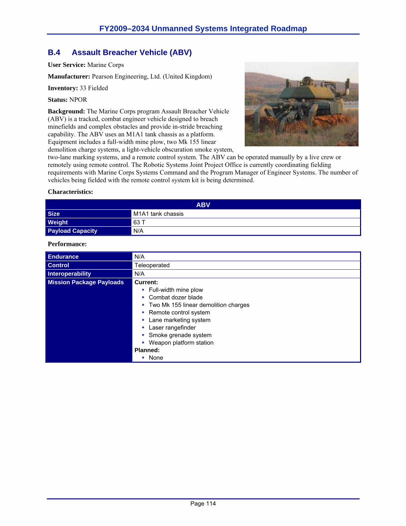
FY2009–2034 Unmanned Systems Integrated Roadmap
Page 114
B.4 Assault Breacher Vehicle (ABV) User Service: Marine Corps
Manufacturer: Pearson Engineering, Ltd. (United Kingdom)
Inventory: 33 Fielded
Status: NPOR
Background: The Marine Corps program Assault Breacher Vehicle (ABV) is a tracked, combat engineer vehicle designed to breach minefields and complex obstacles and provide in-stride breaching capability. The ABV uses an M1A1 tank chassis as a platform. Equipment includes a full-width mine plow, two Mk 155 linear demolition charge systems, a light-vehicle obscuration smoke system, two-lane marking systems, and a remote control system. The ABV can be operated manually by a live crew or remotely using remote control. The Robotic Systems Joint Project Office is currently coordinating fielding requirements with Marine Corps Systems Command and the Program Manager of Engineer Systems. The number of vehicles being fielded with the remote control system kit is being determined.
Characteristics:
ABV Size M1A1 tank chassis Weight 63 T Payload Capacity N/A
Performance:
Endurance N/A Control Teleoperated Interoperability N/A Mission Package Payloads Current:
Full-width mine plow Combat dozer blade Two Mk 155 linear demolition charges Remote control system Lane marketing system Laser rangefinder Smoke grenade system Weapon platform station
Planned: None
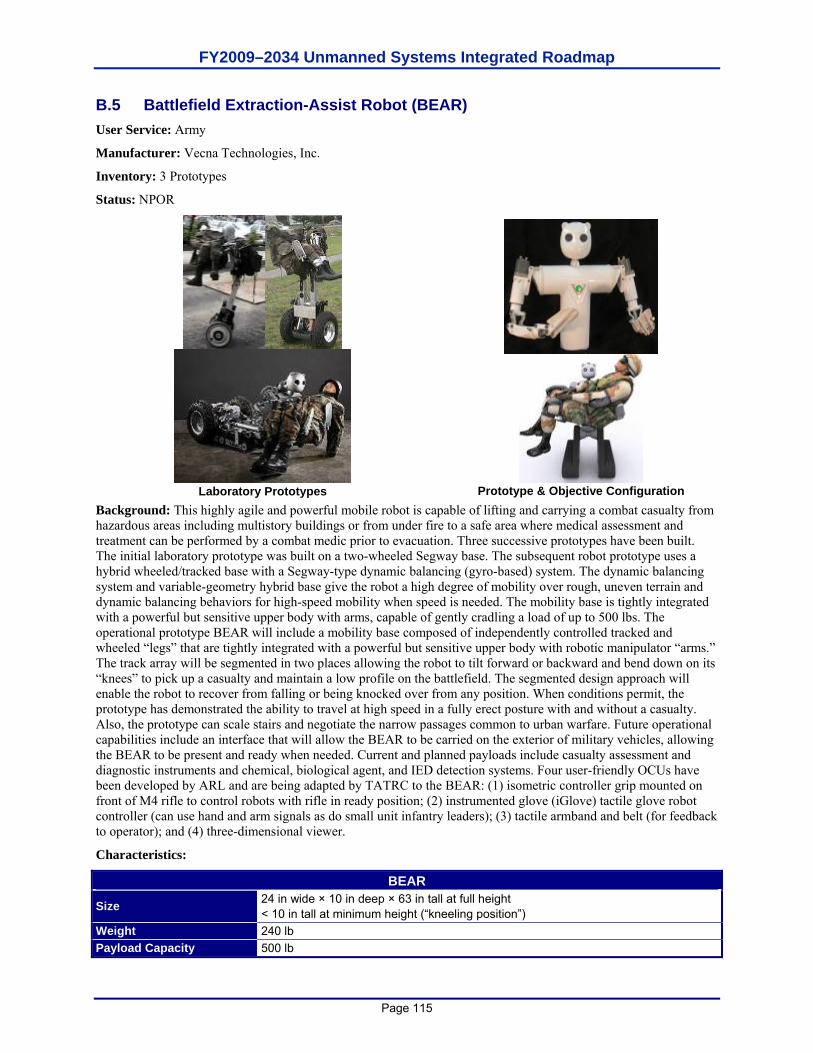
FY2009–2034 Unmanned Systems Integrated Roadmap
Page 115
B.5 Battlefield Extraction-Assist Robot (BEAR) User Service: Army
Manufacturer: Vecna Technologies, Inc.
Inventory: 3 Prototypes
Status: NPOR
Laboratory Prototypes
Prototype & Objective Configuration
Background: This highly agile and powerful mobile robot is capable of lifting and carrying a combat casualty from hazardous areas including multistory buildings or from under fire to a safe area where medical assessment and treatment can be performed by a combat medic prior to evacuation. Three successive prototypes have been built. The initial laboratory prototype was built on a two-wheeled Segway base. The subsequent robot prototype uses a hybrid wheeled/tracked base with a Segway-type dynamic balancing (gyro-based) system. The dynamic balancing system and variable-geometry hybrid base give the robot a high degree of mobility over rough, uneven terrain and dynamic balancing behaviors for high-speed mobility when speed is needed. The mobility base is tightly integrated with a powerful but sensitive upper body with arms, capable of gently cradling a load of up to 500 lbs. The operational prototype BEAR will include a mobility base composed of independently controlled tracked and wheeled “legs” that are tightly integrated with a powerful but sensitive upper body with robotic manipulator “arms.” The track array will be segmented in two places allowing the robot to tilt forward or backward and bend down on its “knees” to pick up a casualty and maintain a low profile on the battlefield. The segmented design approach will enable the robot to recover from falling or being knocked over from any position. When conditions permit, the prototype has demonstrated the ability to travel at high speed in a fully erect posture with and without a casualty. Also, the prototype can scale stairs and negotiate the narrow passages common to urban warfare. Future operational capabilities include an interface that will allow the BEAR to be carried on the exterior of military vehicles, allowing the BEAR to be present and ready when needed. Current and planned payloads include casualty assessment and diagnostic instruments and chemical, biological agent, and IED detection systems. Four user-friendly OCUs have been developed by ARL and are being adapted by TATRC to the BEAR: (1) isometric controller grip mounted on front of M4 rifle to control robots with rifle in ready position; (2) instrumented glove (iGlove) tactile glove robot controller (can use hand and arm signals as do small unit infantry leaders); (3) tactile armband and belt (for feedback to operator); and (4) three-dimensional viewer.
Characteristics:
BEAR
Size 24 in wide × 10 in deep × 63 in tall at full height < 10 in tall at minimum height (“kneeling position”)
Weight 240 lb Payload Capacity 500 lb
FY2009–2034 Unmanned Systems Integrated Roadmap
Page 116
Performance:
Endurance 6 hr of active use on battery; indefinite with solid oxide fuel cell and reformer Control JAUS, teleoperated, semi-autonomous Interoperability JAUS
Mission Package Payloads Current: Casualty assessment and rescue Planned: Chemical/biological/nuclear agent and IED explosive detection
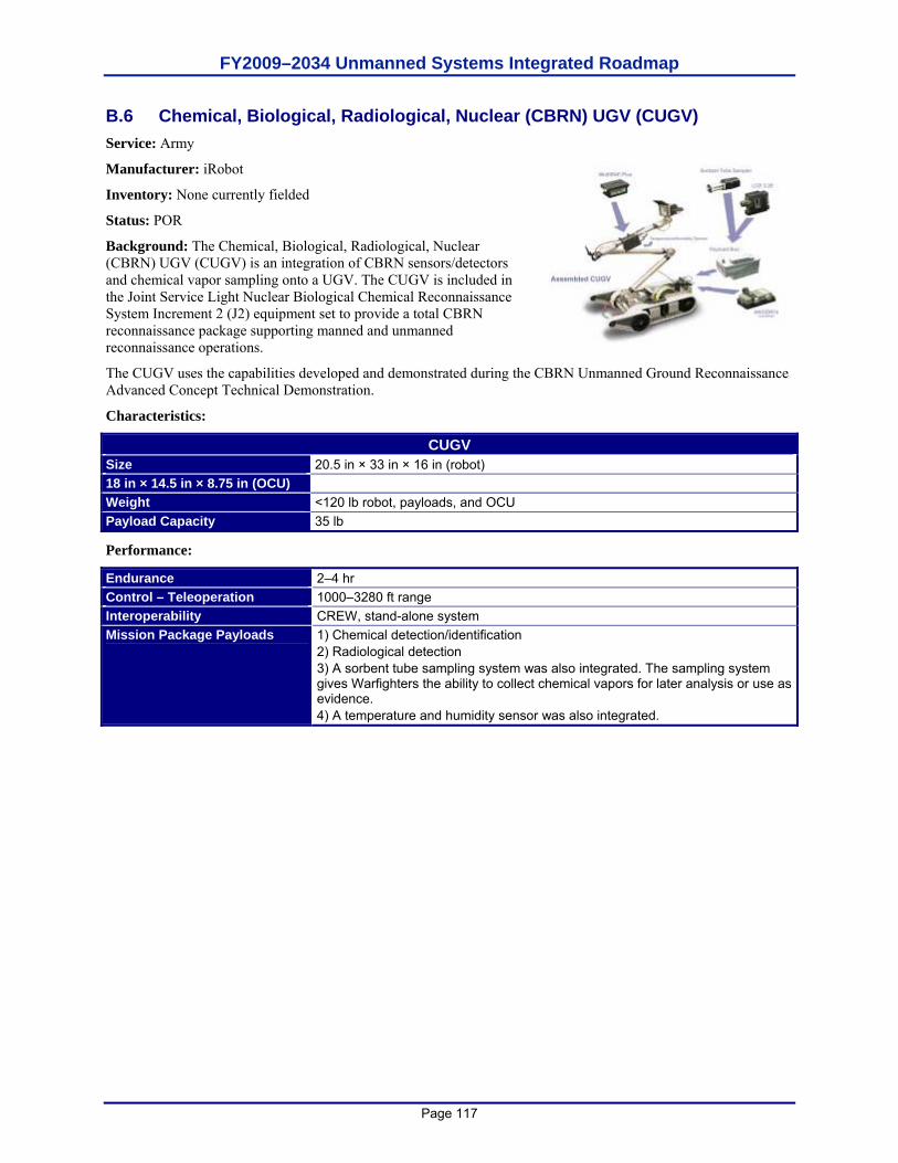
FY2009–2034 Unmanned Systems Integrated Roadmap
Page 117
B.6 Chemical, Biological, Radiological, Nuclear (CBRN) UGV (CUGV) Service: Army
Manufacturer: iRobot
Inventory: None currently fielded
Status: POR
Background: The Chemical, Biological, Radiological, Nuclear (CBRN) UGV (CUGV) is an integration of CBRN sensors/detectors and chemical vapor sampling onto a UGV. The CUGV is included in the Joint Service Light Nuclear Biological Chemical Reconnaissance System Increment 2 (J2) equipment set to provide a total CBRN reconnaissance package supporting manned and unmanned reconnaissance operations.
The CUGV uses the capabilities developed and demonstrated during the CBRN Unmanned Ground Reconnaissance Advanced Concept Technical Demonstration.
Characteristics:
CUGV Size 20.5 in × 33 in × 16 in (robot) 18 in × 14.5 in × 8.75 in (OCU) Weight <120 lb robot, payloads, and OCU Payload Capacity 35 lb
Performance:
Endurance 2–4 hr Control – Teleoperation 1000–3280 ft range Interoperability CREW, stand-alone system Mission Package Payloads 1) Chemical detection/identification
2) Radiological detection 3) A sorbent tube sampling system was also integrated. The sampling system gives Warfighters the ability to collect chemical vapors for later analysis or use as evidence. 4) A temperature and humidity sensor was also integrated.
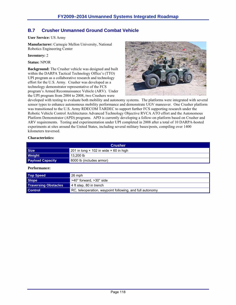
FY2009–2034 Unmanned Systems Integrated Roadmap
Page 118
B.7 Crusher Unmanned Ground Combat Vehicle User Service: US Army
Manufacturer: Carnegie Mellon University, National Robotics Engineering Center
Inventory: 2
Status: NPOR
Background: The Crusher vehicle was designed and built within the DARPA Tactical Technology Office’s (TTO) UPI program as a collaborative research and technology effort for the U.S. Army. Crusher was developed as a technology demonstrator representative of the FCS program’s Armed Reconnaissance Vehicle (ARV). Under the UPI program from 2004 to 2008, two Crushers were developed with testing to evaluate both mobility and autonomy systems. The platforms were integrated with several sensor types to enhance autonomous mobility performance and demonstrate UGV maneuver. One Crusher platform was transitioned to the U.S. Army RDECOM TARDEC to support further FCS supporting research under the Robotic Vehicle Control Architectures Advanced Technology Objective RVCA ATO effort and the Autonomous Platform Demonstrator (APD) programs. APD is currently developing a follow-on platform based on Crusher and ARV requirements. Testing and experimentation under UPI completed in 2008 after a total of 10 DARPA-hosted experiments at sites around the United States, including several military bases/posts, compiling over 1400 kilometers traversed.
Characteristics:
Crusher Size 201 in long × 102 in wide × 60 in high Weight 13,200 lb Payload Capacity 8000 lb (includes armor)
Performance:
Top Speed 26 mph Slope >40° forward, >30° side Traversing Obstacles 4 ft step, 80 in trench Control RC, teleoperation, waypoint following, and full autonomy
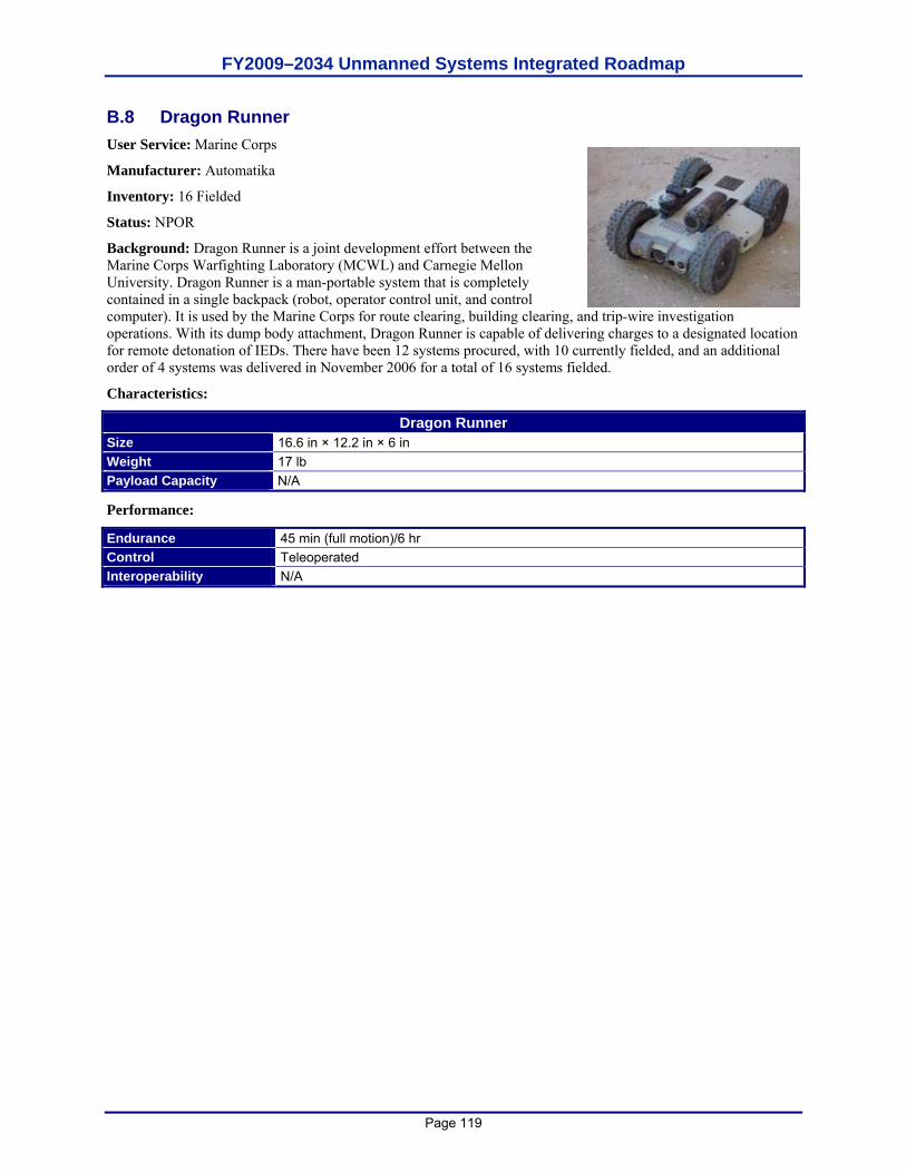
FY2009–2034 Unmanned Systems Integrated Roadmap
Page 119
B.8 Dragon Runner User Service: Marine Corps
Manufacturer: Automatika
Inventory: 16 Fielded
Status: NPOR
Background: Dragon Runner is a joint development effort between the Marine Corps Warfighting Laboratory (MCWL) and Carnegie Mellon University. Dragon Runner is a man-portable system that is completely contained in a single backpack (robot, operator control unit, and control computer). It is used by the Marine Corps for route clearing, building clearing, and trip-wire investigation operations. With its dump body attachment, Dragon Runner is capable of delivering charges to a designated location for remote detonation of IEDs. There have been 12 systems procured, with 10 currently fielded, and an additional order of 4 systems was delivered in November 2006 for a total of 16 systems fielded.
Characteristics:
Dragon Runner Size 16.6 in × 12.2 in × 6 in Weight 17 lb Payload Capacity N/A
Performance:
Endurance 45 min (full motion)/6 hr Control Teleoperated Interoperability N/A
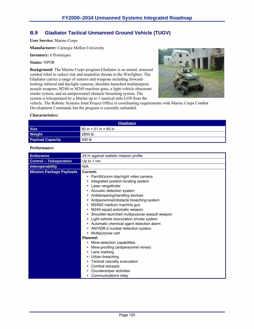
FY2009–2034 Unmanned Systems Integrated Roadmap
Page 120
B.9 Gladiator Tactical Unmanned Ground Vehicle (TUGV) User Service: Marine Corps
Manufacturer: Carnegie Mellon University
Inventory: 6 Prototypes
Status: NPOR
Background: The Marine Corps program Gladiator is an armed, armored combat robot to reduce risk and neutralize threats to the Warfighter. The Gladiator carries a range of sensors and weapons including forward-looking infrared and daylight cameras, shoulder-launched multipurpose assault weapons, M240 or M249 machine guns, a light-vehicle obscurant smoke system, and an antipersonnel obstacle breaching system. The system is teleoperated by a Marine up to 1 nautical mile LOS from the vehicle. The Robotic Systems Joint Project Office is coordinating requirements with Marine Corps Combat Development Command, but the program is currently unfunded.
Characteristics:
Gladiator Size 80 in × 51 in × 60 in Weight 2800 lb Payload Capacity 400 lb
Performance:
Endurance 24 hr against realistic mission profile Control – Teleoperation Up to 1 nm Interoperability N/A Mission Package Payloads Current:
Pan/tilt/zoom day/night video camera Integrated position-locating system Laser rangefinder Acoustic detection system Antitampering/handling devices Antipersonnel/obstacle breaching system M240G medium machine gun M249 squad automatic weapon Shoulder-launched multipurpose assault weapon Light-vehicle obscuration smoke system Automatic chemical agent detection alarm AN/VDR-2 nuclear detection system Multipurpose cart
Planned: Mine-detection capabilities Mine-proofing (antipersonnel mines) Lane marking Urban breaching Tactical casualty evacuation Combat resupply Countersniper activities Communications relay
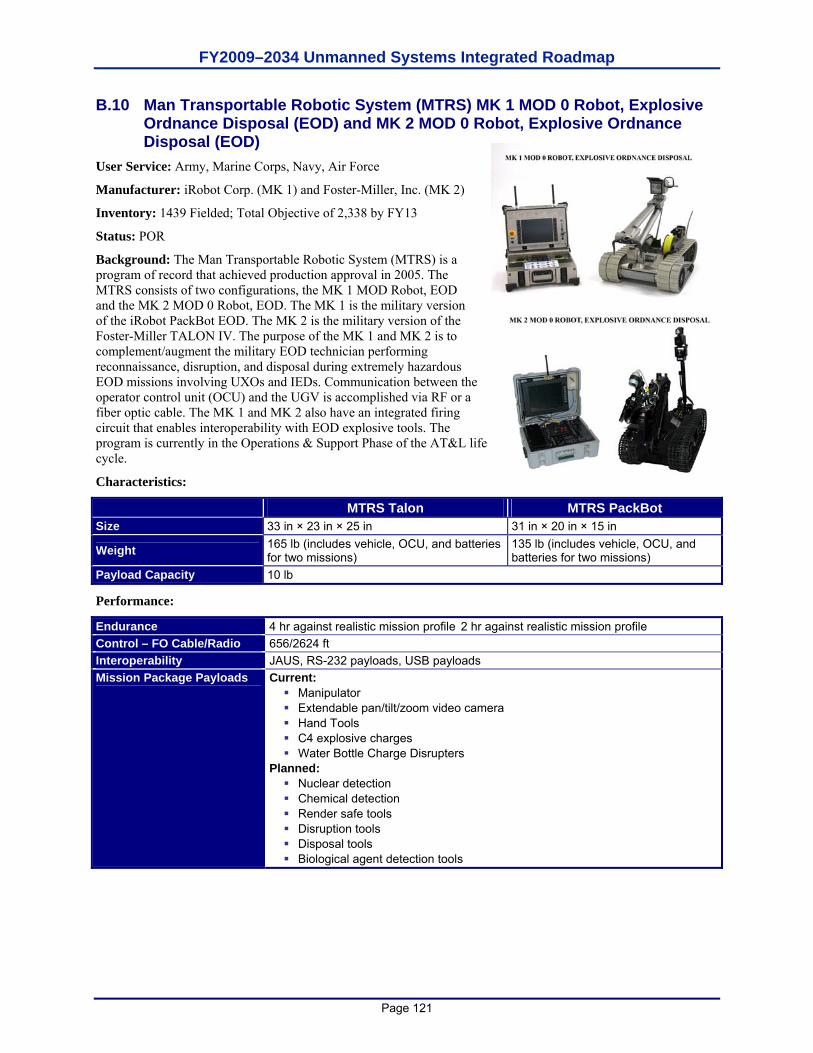
FY2009–2034 Unmanned Systems Integrated Roadmap
Page 121
B.10 Man Transportable Robotic System (MTRS) MK 1 MOD 0 Robot, Explosive Ordnance Disposal (EOD) and MK 2 MOD 0 Robot, Explosive Ordnance Disposal (EOD)
User Service: Army, Marine Corps, Navy, Air Force
Manufacturer: iRobot Corp. (MK 1) and Foster-Miller, Inc. (MK 2)
Inventory: 1439 Fielded; Total Objective of 2,338 by FY13
Status: POR
Background: The Man Transportable Robotic System (MTRS) is a program of record that achieved production approval in 2005. The MTRS consists of two configurations, the MK 1 MOD Robot, EOD and the MK 2 MOD 0 Robot, EOD. The MK 1 is the military version of the iRobot PackBot EOD. The MK 2 is the military version of the Foster-Miller TALON IV. The purpose of the MK 1 and MK 2 is to complement/augment the military EOD technician performing reconnaissance, disruption, and disposal during extremely hazardous EOD missions involving UXOs and IEDs. Communication between the operator control unit (OCU) and the UGV is accomplished via RF or a fiber optic cable. The MK 1 and MK 2 also have an integrated firing circuit that enables interoperability with EOD explosive tools. The program is currently in the Operations & Support Phase of the AT&L life cycle.
Characteristics:
MTRS Talon MTRS PackBot Size 33 in × 23 in × 25 in 31 in × 20 in × 15 in
Weight 165 lb (includes vehicle, OCU, and batteries for two missions)
135 lb (includes vehicle, OCU, and batteries for two missions)
Payload Capacity 10 lb
Performance:
Endurance 4 hr against realistic mission profile 2 hr against realistic mission profile Control – FO Cable/Radio 656/2624 ft Interoperability JAUS, RS-232 payloads, USB payloads Mission Package Payloads Current:
Manipulator Extendable pan/tilt/zoom video camera Hand Tools C4 explosive charges Water Bottle Charge Disrupters
Planned: Nuclear detection Chemical detection Render safe tools Disruption tools Disposal tools Biological agent detection tools
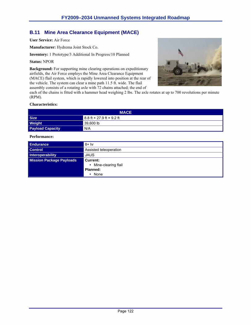
FY2009–2034 Unmanned Systems Integrated Roadmap
Page 122
B.11 Mine Area Clearance Equipment (MACE) User Service: Air Force
Manufacturer: Hydrema Joint Stock Co.
Inventory: 1 Prototype/3 Additional In Progress/10 Planned
Status: NPOR
Background: For supporting mine clearing operations on expeditionary airfields, the Air Force employs the Mine Area Clearance Equipment (MACE) flail system, which is rapidly lowered into position at the rear of the vehicle. The system can clear a mine path 11.5 ft. wide. The flail assembly consists of a rotating axle with 72 chains attached; the end of each of the chains is fitted with a hammer head weighing 2 lbs. The axle rotates at up to 700 revolutions per minute (RPM).
Characteristics:
MACE Size 8.8 ft × 27.9 ft × 9.2 ft Weight 39,600 lb Payload Capacity N/A
Performance:
Endurance 8+ hr Control Assisted teleoperation Interoperability JAUS Mission Package Payloads Current:
Mine-clearing flail Planned:
None
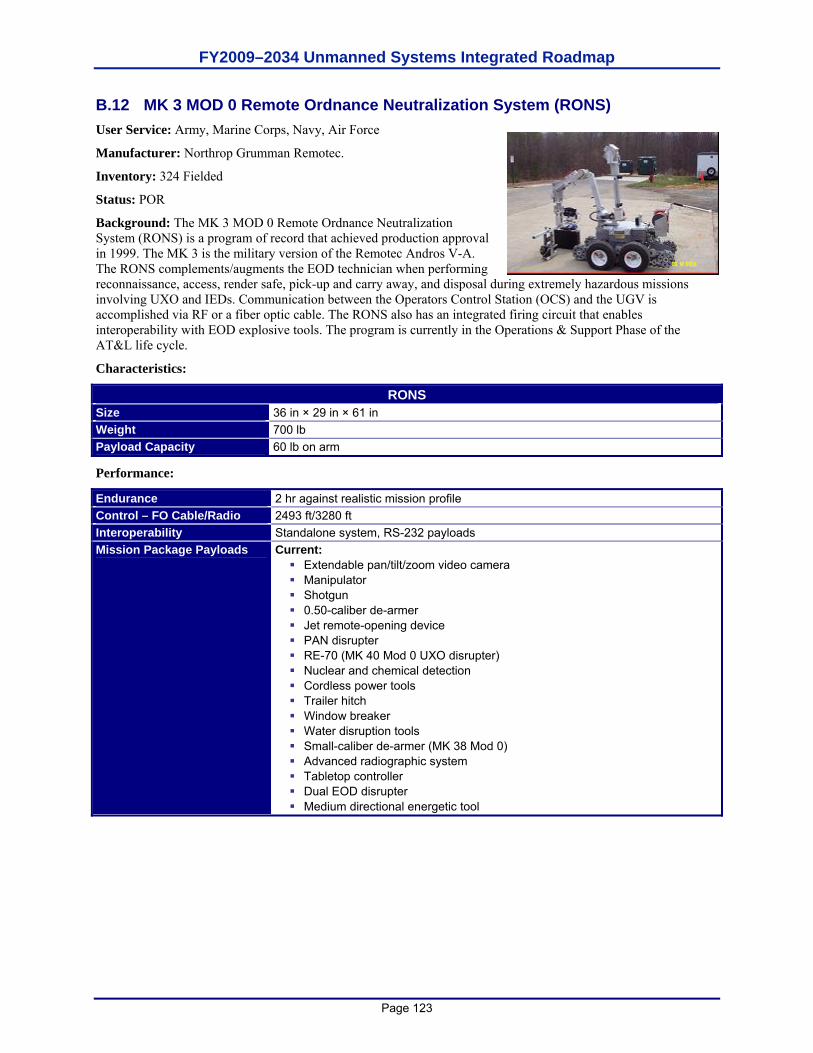
FY2009–2034 Unmanned Systems Integrated Roadmap
Page 123
B.12 MK 3 MOD 0 Remote Ordnance Neutralization System (RONS) User Service: Army, Marine Corps, Navy, Air Force
Manufacturer: Northrop Grumman Remotec.
Inventory: 324 Fielded
Status: POR
Background: The MK 3 MOD 0 Remote Ordnance Neutralization System (RONS) is a program of record that achieved production approval in 1999. The MK 3 is the military version of the Remotec Andros V-A. The RONS complements/augments the EOD technician when performing reconnaissance, access, render safe, pick-up and carry away, and disposal during extremely hazardous missions involving UXO and IEDs. Communication between the Operators Control Station (OCS) and the UGV is accomplished via RF or a fiber optic cable. The RONS also has an integrated firing circuit that enables interoperability with EOD explosive tools. The program is currently in the Operations & Support Phase of the AT&L life cycle.
Characteristics:
RONS Size 36 in × 29 in × 61 in Weight 700 lb Payload Capacity 60 lb on arm
Performance:
Endurance 2 hr against realistic mission profile Control – FO Cable/Radio 2493 ft/3280 ft Interoperability Standalone system, RS-232 payloads Mission Package Payloads Current:
Extendable pan/tilt/zoom video camera Manipulator Shotgun 0.50-caliber de-armer Jet remote-opening device PAN disrupter RE-70 (MK 40 Mod 0 UXO disrupter) Nuclear and chemical detection Cordless power tools Trailer hitch Window breaker Water disruption tools Small-caliber de-armer (MK 38 Mod 0) Advanced radiographic system Tabletop controller Dual EOD disrupter Medium directional energetic tool
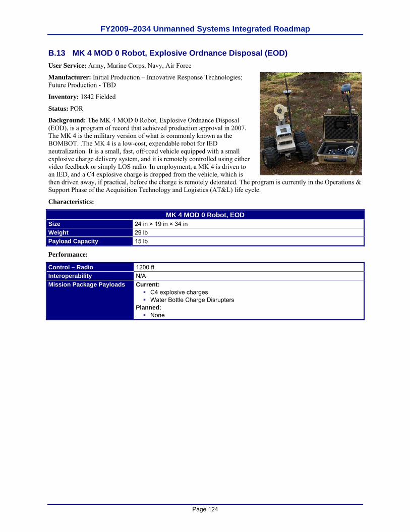
FY2009–2034 Unmanned Systems Integrated Roadmap
Page 124
B.13 MK 4 MOD 0 Robot, Explosive Ordnance Disposal (EOD) User Service: Army, Marine Corps, Navy, Air Force
Manufacturer: Initial Production – Innovative Response Technologies; Future Production - TBD
Inventory: 1842 Fielded
Status: POR
Background: The MK 4 MOD 0 Robot, Explosive Ordnance Disposal (EOD), is a program of record that achieved production approval in 2007. The MK 4 is the military version of what is commonly known as the BOMBOT. .The MK 4 is a low-cost, expendable robot for IED neutralization. It is a small, fast, off-road vehicle equipped with a small explosive charge delivery system, and it is remotely controlled using either video feedback or simply LOS radio. In employment, a MK 4 is driven to an IED, and a C4 explosive charge is dropped from the vehicle, which is then driven away, if practical, before the charge is remotely detonated. The program is currently in the Operations & Support Phase of the Acquisition Technology and Logistics (AT&L) life cycle.
Characteristics:
MK 4 MOD 0 Robot, EOD Size 24 in × 19 in × 34 in Weight 29 lb Payload Capacity 15 lb
Performance:
Control – Radio 1200 ft Interoperability N/A Mission Package Payloads Current:
C4 explosive charges Water Bottle Charge Disrupters
Planned: None
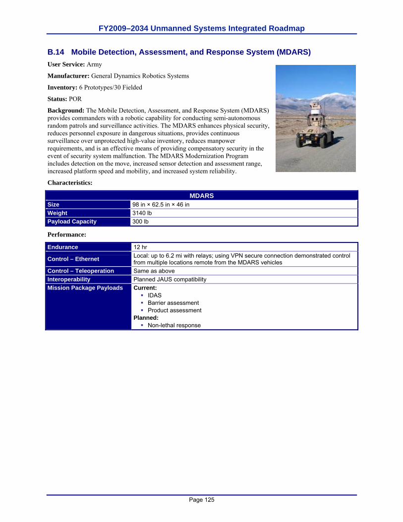
FY2009–2034 Unmanned Systems Integrated Roadmap
Page 125
B.14 Mobile Detection, Assessment, and Response System (MDARS) User Service: Army
Manufacturer: General Dynamics Robotics Systems
Inventory: 6 Prototypes/30 Fielded
Status: POR
Background: The Mobile Detection, Assessment, and Response System (MDARS) provides commanders with a robotic capability for conducting semi-autonomous random patrols and surveillance activities. The MDARS enhances physical security, reduces personnel exposure in dangerous situations, provides continuous surveillance over unprotected high-value inventory, reduces manpower requirements, and is an effective means of providing compensatory security in the event of security system malfunction. The MDARS Modernization Program includes detection on the move, increased sensor detection and assessment range, increased platform speed and mobility, and increased system reliability.
Characteristics:
MDARS Size 98 in × 62.5 in × 46 in Weight 3140 lb Payload Capacity 300 lb
Performance:
Endurance 12 hr
Control – Ethernet Local: up to 6.2 mi with relays; using VPN secure connection demonstrated control from multiple locations remote from the MDARS vehicles
Control – Teleoperation Same as above Interoperability Planned JAUS compatibility Mission Package Payloads Current:
IDAS Barrier assessment Product assessment
Planned: Non-lethal response
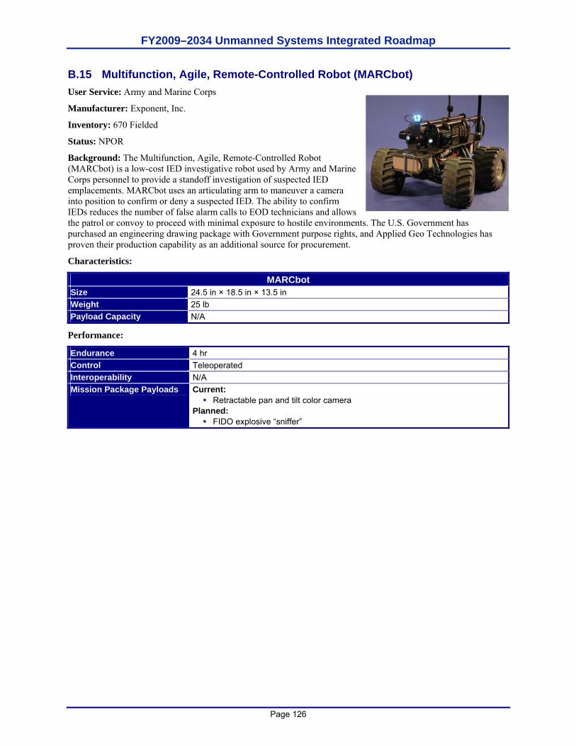
FY2009–2034 Unmanned Systems Integrated Roadmap
Page 126
B.15 Multifunction, Agile, Remote-Controlled Robot (MARCbot) User Service: Army and Marine Corps
Manufacturer: Exponent, Inc.
Inventory: 670 Fielded
Status: NPOR
Background: The Multifunction, Agile, Remote-Controlled Robot (MARCbot) is a low-cost IED investigative robot used by Army and Marine Corps personnel to provide a standoff investigation of suspected IED emplacements. MARCbot uses an articulating arm to maneuver a camera into position to confirm or deny a suspected IED. The ability to confirm IEDs reduces the number of false alarm calls to EOD technicians and allows the patrol or convoy to proceed with minimal exposure to hostile environments. The U.S. Government has purchased an engineering drawing package with Government purpose rights, and Applied Geo Technologies has proven their production capability as an additional source for procurement.
Characteristics:
MARCbot Size 24.5 in × 18.5 in × 13.5 in Weight 25 lb Payload Capacity N/A
Performance:
Endurance 4 hr Control Teleoperated Interoperability N/A Mission Package Payloads Current:
Retractable pan and tilt color camera Planned:
FIDO explosive “sniffer”
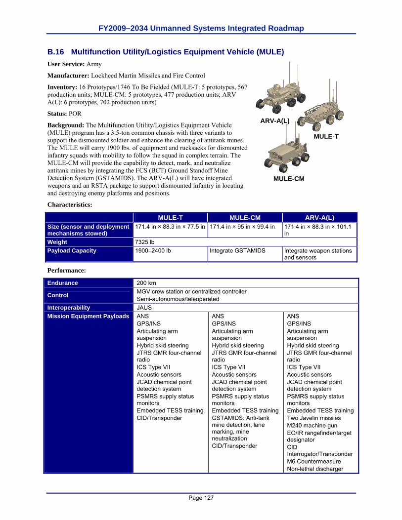
FY2009–2034 Unmanned Systems Integrated Roadmap
Page 127
B.16 Multifunction Utility/Logistics Equipment Vehicle (MULE) User Service: Army
Manufacturer: Lockheed Martin Missiles and Fire Control
Inventory: 16 Prototypes/1746 To Be Fielded (MULE-T: 5 prototypes, 567 production units; MULE-CM: 5 prototypes, 477 production units; ARV A(L): 6 prototypes, 702 production units)
Status: POR
Background: The Multifunction Utility/Logistics Equipment Vehicle (MULE) program has a 3.5-ton common chassis with three variants to support the dismounted soldier and enhance the clearing of antitank mines. The MULE will carry 1900 lbs. of equipment and rucksacks for dismounted infantry squads with mobility to follow the squad in complex terrain. The MULE-CM will provide the capability to detect, mark, and neutralize antitank mines by integrating the FCS (BCT) Ground Standoff Mine Detection System (GSTAMIDS). The ARV-A(L) will have integrated weapons and an RSTA package to support dismounted infantry in locating and destroying enemy platforms and positions.
Characteristics:
MULE-T MULE-CM ARV-A(L) Size (sensor and deployment mechanisms stowed)
171.4 in × 88.3 in × 77.5 in 171.4 in × 95 in × 99.4 in 171.4 in × 88.3 in × 101.1 in
Weight 7325 lb Payload Capacity 1900–2400 lb Integrate GSTAMIDS Integrate weapon stations
and sensors
Performance:
Endurance 200 km
Control MGV crew station or centralized controller Semi-autonomous/teleoperated
Interoperability JAUS Mission Equipment Payloads ANS
GPS/INS Articulating arm suspension Hybrid skid steering JTRS GMR four-channel radio ICS Type VII Acoustic sensors JCAD chemical point detection system PSMRS supply status monitors Embedded TESS training CID/Transponder
ANS GPS/INS Articulating arm suspension Hybrid skid steering JTRS GMR four-channel radio ICS Type VII Acoustic sensors JCAD chemical point detection system PSMRS supply status monitors Embedded TESS training GSTAMIDS: Anti-tank mine detection, lane marking, mine neutralization CID/Transponder
ANS GPS/INS Articulating arm suspension Hybrid skid steering JTRS GMR four-channel radio ICS Type VII Acoustic sensors JCAD chemical point detection system PSMRS supply status monitors Embedded TESS training Two Javelin missiles M240 machine gun EO/IR rangefinder/target designator CID Interrogator/Transponder M6 Countermeasure Non-lethal discharger
ARV-A(L)
MULE-T
MULE-CM
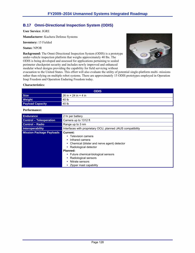
FY2009–2034 Unmanned Systems Integrated Roadmap
Page 128
B.17 Omni-Directional Inspection System (ODIS) User Service: JGRE
Manufacturer: Kuchera Defense Systems
Inventory: 15 Fielded
Status: NPOR
Background: The Omni-Directional Inspection System (ODIS) is a prototype under-vehicle inspection platform that weighs approximately 40 lbs. The ODIS is being developed and assessed for applications pertaining to sealed perimeter checkpoint security and includes newly improved and enhanced modular wheel designs providing the capability for field servicing without evacuation to the United States. This effort will also evaluate the utility of potential single-platform multi- missions rather than relying on multiple robot systems. There are approximately 15 ODIS prototypes employed in Operation Iraqi Freedom and Operation Enduring Freedom today.
Characteristics:
ODIS Size 26 in × 24 in × 4 in Weight 40 lb Payload Capacity 40 lb
Performance:
Endurance 2 hr per battery Control – Teleoperation Camera up to 1312 ft Control – Radio Range up to 3 nm Interoperability Interfaces with proprietary OCU, planned JAUS compatibility Mission Package Payloads Current:
Television camera Infrared camera Chemical (blister and nerve agent) detector Radiological detector
Planned: Future chemical-biological sensors Radiological sensors Nitrate sensors Zipper mast capability
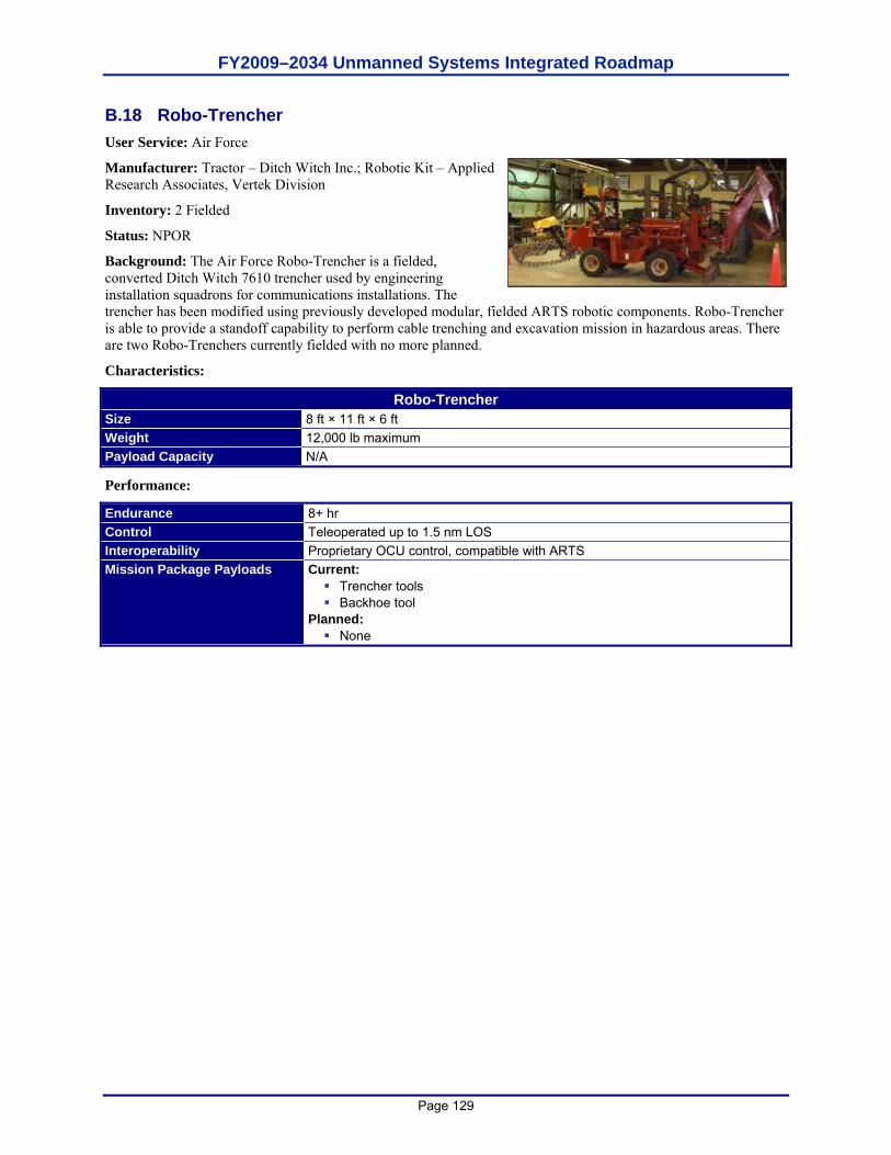
FY2009–2034 Unmanned Systems Integrated Roadmap
Page 129
B.18 Robo-Trencher User Service: Air Force
Manufacturer: Tractor – Ditch Witch Inc.; Robotic Kit – Applied Research Associates, Vertek Division
Inventory: 2 Fielded
Status: NPOR
Background: The Air Force Robo-Trencher is a fielded, converted Ditch Witch 7610 trencher used by engineering installation squadrons for communications installations. The trencher has been modified using previously developed modular, fielded ARTS robotic components. Robo-Trencher is able to provide a standoff capability to perform cable trenching and excavation mission in hazardous areas. There are two Robo-Trenchers currently fielded with no more planned.
Characteristics:
Robo-Trencher Size 8 ft × 11 ft × 6 ft Weight 12,000 lb maximum Payload Capacity N/A
Performance:
Endurance 8+ hr Control Teleoperated up to 1.5 nm LOS Interoperability Proprietary OCU control, compatible with ARTS Mission Package Payloads Current:
Trencher tools Backhoe tool
Planned: None
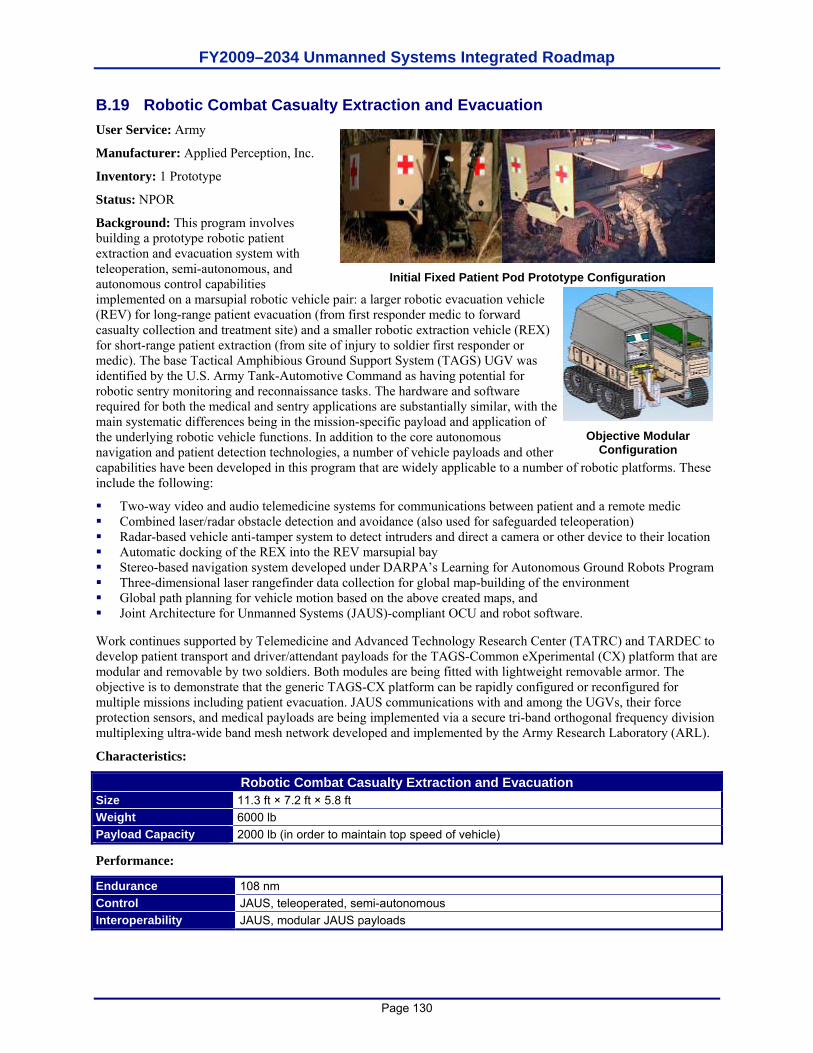
FY2009–2034 Unmanned Systems Integrated Roadmap
Page 130
B.19 Robotic Combat Casualty Extraction and Evacuation User Service: Army
Manufacturer: Applied Perception, Inc.
Inventory: 1 Prototype
Status: NPOR
Background: This program involves building a prototype robotic patient extraction and evacuation system with teleoperation, semi-autonomous, and autonomous control capabilities implemented on a marsupial robotic vehicle pair: a larger robotic evacuation vehicle (REV) for long-range patient evacuation (from first responder medic to forward casualty collection and treatment site) and a smaller robotic extraction vehicle (REX) for short-range patient extraction (from site of injury to soldier first responder or medic). The base Tactical Amphibious Ground Support System (TAGS) UGV was identified by the U.S. Army Tank-Automotive Command as having potential for robotic sentry monitoring and reconnaissance tasks. The hardware and software required for both the medical and sentry applications are substantially similar, with the main systematic differences being in the mission-specific payload and application of the underlying robotic vehicle functions. In addition to the core autonomous navigation and patient detection technologies, a number of vehicle payloads and other capabilities have been developed in this program that are widely applicable to a number of robotic platforms. These include the following:
Two-way video and audio telemedicine systems for communications between patient and a remote medic Combined laser/radar obstacle detection and avoidance (also used for safeguarded teleoperation) Radar-based vehicle anti-tamper system to detect intruders and direct a camera or other device to their location Automatic docking of the REX into the REV marsupial bay Stereo-based navigation system developed under DARPA’s Learning for Autonomous Ground Robots Program Three-dimensional laser rangefinder data collection for global map-building of the environment Global path planning for vehicle motion based on the above created maps, and Joint Architecture for Unmanned Systems (JAUS)-compliant OCU and robot software.
Work continues supported by Telemedicine and Advanced Technology Research Center (TATRC) and TARDEC to develop patient transport and driver/attendant payloads for the TAGS-Common eXperimental (CX) platform that are modular and removable by two soldiers. Both modules are being fitted with lightweight removable armor. The objective is to demonstrate that the generic TAGS-CX platform can be rapidly configured or reconfigured for multiple missions including patient evacuation. JAUS communications with and among the UGVs, their force protection sensors, and medical payloads are being implemented via a secure tri-band orthogonal frequency division multiplexing ultra-wide band mesh network developed and implemented by the Army Research Laboratory (ARL).
Characteristics:
Robotic Combat Casualty Extraction and Evacuation Size 11.3 ft × 7.2 ft × 5.8 ft Weight 6000 lb Payload Capacity 2000 lb (in order to maintain top speed of vehicle)
Performance:
Endurance 108 nm Control JAUS, teleoperated, semi-autonomous Interoperability JAUS, modular JAUS payloads
Initial Fixed Patient Pod Prototype Configuration
Objective Modular Configuration
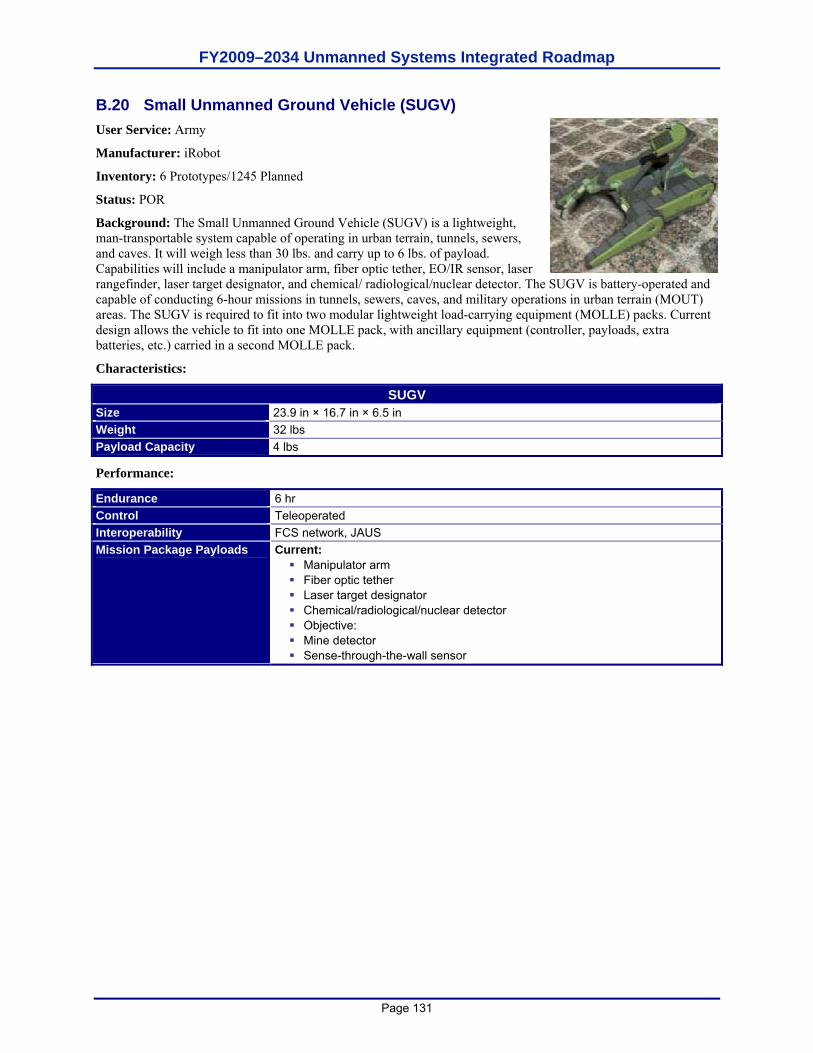
FY2009–2034 Unmanned Systems Integrated Roadmap
Page 131
B.20 Small Unmanned Ground Vehicle (SUGV) User Service: Army
Manufacturer: iRobot
Inventory: 6 Prototypes/1245 Planned
Status: POR
Background: The Small Unmanned Ground Vehicle (SUGV) is a lightweight, man-transportable system capable of operating in urban terrain, tunnels, sewers, and caves. It will weigh less than 30 lbs. and carry up to 6 lbs. of payload. Capabilities will include a manipulator arm, fiber optic tether, EO/IR sensor, laser rangefinder, laser target designator, and chemical/ radiological/nuclear detector. The SUGV is battery-operated and capable of conducting 6-hour missions in tunnels, sewers, caves, and military operations in urban terrain (MOUT) areas. The SUGV is required to fit into two modular lightweight load-carrying equipment (MOLLE) packs. Current design allows the vehicle to fit into one MOLLE pack, with ancillary equipment (controller, payloads, extra batteries, etc.) carried in a second MOLLE pack.
Characteristics:
SUGV Size 23.9 in × 16.7 in × 6.5 in Weight 32 lbs Payload Capacity 4 lbs
Performance:
Endurance 6 hr Control Teleoperated Interoperability FCS network, JAUS Mission Package Payloads Current:
Manipulator arm Fiber optic tether Laser target designator Chemical/radiological/nuclear detector Objective: Mine detector Sense-through-the-wall sensor
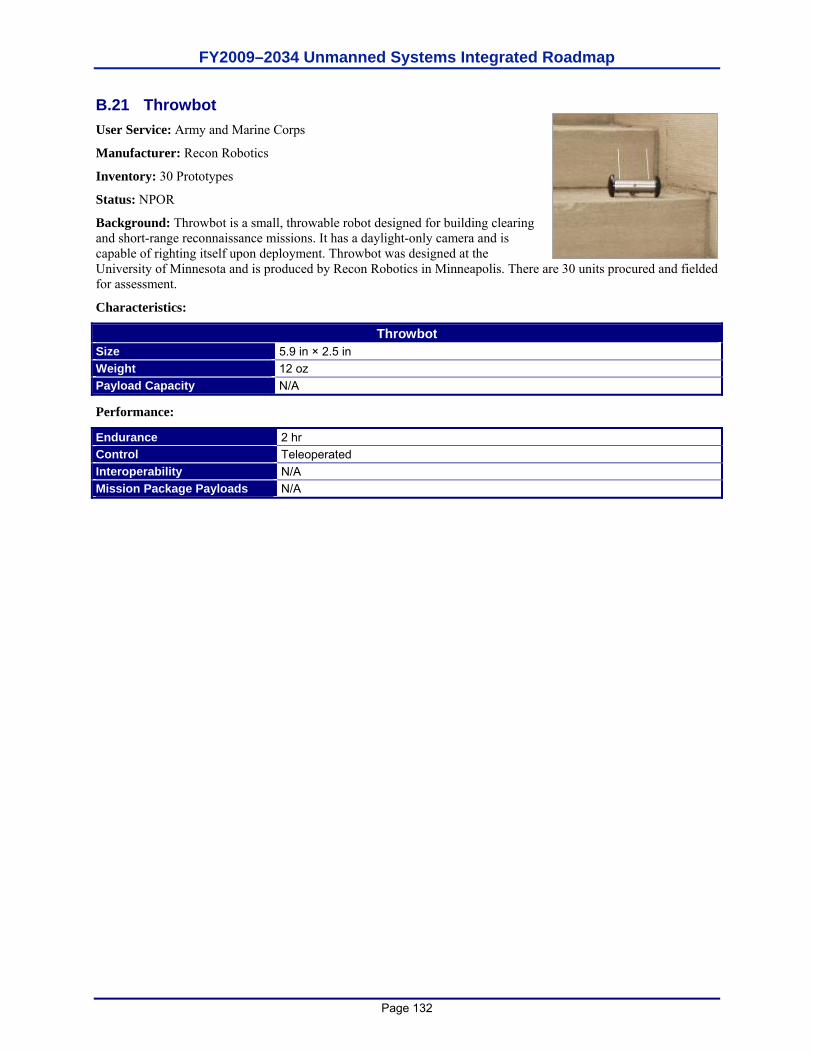
FY2009–2034 Unmanned Systems Integrated Roadmap
Page 132
B.21 Throwbot User Service: Army and Marine Corps
Manufacturer: Recon Robotics
Inventory: 30 Prototypes
Status: NPOR
Background: Throwbot is a small, throwable robot designed for building clearing and short-range reconnaissance missions. It has a daylight-only camera and is capable of righting itself upon deployment. Throwbot was designed at the University of Minnesota and is produced by Recon Robotics in Minneapolis. There are 30 units procured and fielded for assessment.
Characteristics:
Throwbot Size 5.9 in × 2.5 in Weight 12 oz Payload Capacity N/A
Performance:
Endurance 2 hr Control Teleoperated Interoperability N/A Mission Package Payloads N/A
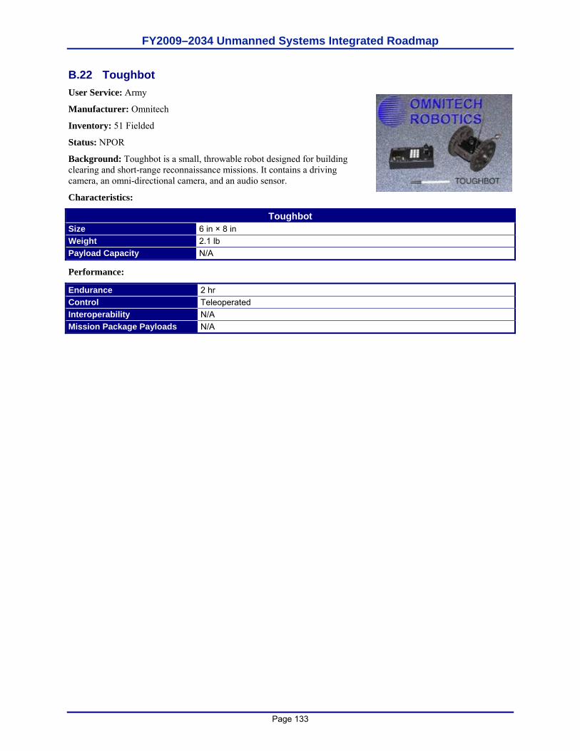
FY2009–2034 Unmanned Systems Integrated Roadmap
Page 133
B.22 Toughbot User Service: Army
Manufacturer: Omnitech
Inventory: 51 Fielded
Status: NPOR
Background: Toughbot is a small, throwable robot designed for building clearing and short-range reconnaissance missions. It contains a driving camera, an omni-directional camera, and an audio sensor.
Characteristics:
Toughbot Size 6 in × 8 in Weight 2.1 lb Payload Capacity N/A
Performance:
Endurance 2 hr Control Teleoperated Interoperability N/A Mission Package Payloads N/A

FY2009–2034 Unmanned Systems Integrated Roadmap
Page 134
This page is intentionally left blank.
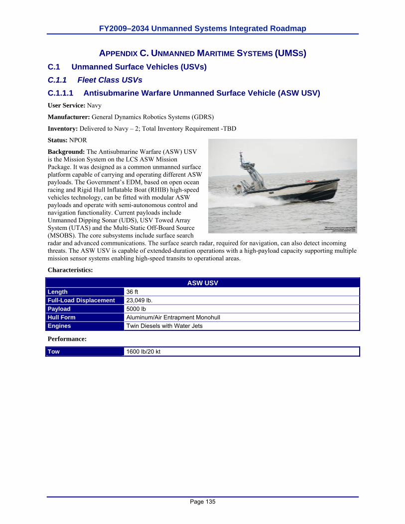
FY2009–2034 Unmanned Systems Integrated Roadmap
Page 135
APPENDIX C. UNMANNED MARITIME SYSTEMS (UMSS) C.1 Unmanned Surface Vehicles (USVs) C.1.1 Fleet Class USVs C.1.1.1 Antisubmarine Warfare Unmanned Surface Vehicle (ASW USV) User Service: Navy
Manufacturer: General Dynamics Robotics Systems (GDRS)
Inventory: Delivered to Navy – 2; Total Inventory Requirement -TBD
Status: NPOR
Background: The Antisubmarine Warfare (ASW) USV is the Mission System on the LCS ASW Mission Package. It was designed as a common unmanned surface platform capable of carrying and operating different ASW payloads. The Government’s EDM, based on open ocean racing and Rigid Hull Inflatable Boat (RHIB) high-speed vehicles technology, can be fitted with modular ASW payloads and operate with semi-autonomous control and navigation functionality. Current payloads include Unmanned Dipping Sonar (UDS), USV Towed Array System (UTAS) and the Multi-Static Off-Board Source (MSOBS). The core subsystems include surface search radar and advanced communications. The surface search radar, required for navigation, can also detect incoming threats. The ASW USV is capable of extended-duration operations with a high-payload capacity supporting multiple mission sensor systems enabling high-speed transits to operational areas.
Characteristics:
ASW USV Length 36 ft Full-Load Displacement 23,049 lb. Payload 5000 lb Hull Form Aluminum/Air Entrapment Monohull Engines Twin Diesels with Water Jets
Performance:
Tow 1600 lb/20 kt
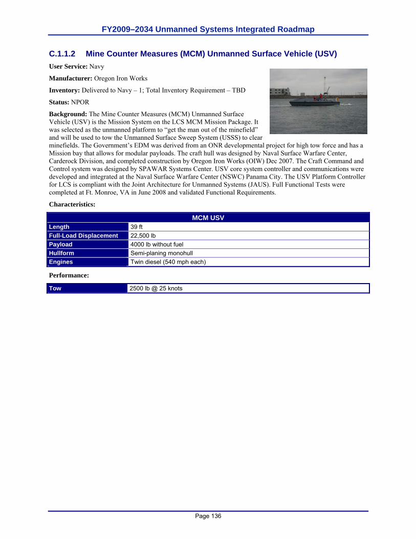
FY2009–2034 Unmanned Systems Integrated Roadmap
Page 136
C.1.1.2 Mine Counter Measures (MCM) Unmanned Surface Vehicle (USV) User Service: Navy
Manufacturer: Oregon Iron Works
Inventory: Delivered to Navy – 1; Total Inventory Requirement – TBD
Status: NPOR
Background: The Mine Counter Measures (MCM) Unmanned Surface Vehicle (USV) is the Mission System on the LCS MCM Mission Package. It was selected as the unmanned platform to “get the man out of the minefield” and will be used to tow the Unmanned Surface Sweep System (USSS) to clear minefields. The Government’s EDM was derived from an ONR developmental project for high tow force and has a Mission bay that allows for modular payloads. The craft hull was designed by Naval Surface Warfare Center, Carderock Division, and completed construction by Oregon Iron Works (OIW) Dec 2007. The Craft Command and Control system was designed by SPAWAR Systems Center. USV core system controller and communications were developed and integrated at the Naval Surface Warfare Center (NSWC) Panama City. The USV Platform Controller for LCS is compliant with the Joint Architecture for Unmanned Systems (JAUS). Full Functional Tests were completed at Ft. Monroe, VA in June 2008 and validated Functional Requirements.
Characteristics:
MCM USV Length 39 ft Full-Load Displacement 22,500 lb Payload 4000 lb without fuel Hullform Semi-planing monohull Engines Twin diesel (540 mph each)
Performance:
Tow 2500 lb @ 25 knots
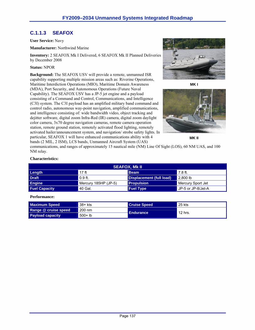
FY2009–2034 Unmanned Systems Integrated Roadmap
Page 137
C.1.1.3 SEAFOX User Service: Navy
Manufacturer: Northwind Marine
Inventory: 2 SEAFOX Mk I Delivered, 6 SEAFOX Mk II Planned Deliveries by December 2008
Status: NPOR
Background: The SEAFOX USV will provide a remote, unmanned ISR capability supporting multiple mission areas such as: Riverine Operations, Maritime Interdiction Operations (MIO), Maritime Domain Awareness (MDA), Port Security, and Autonomous Operations (Future Naval Capability). The SEAFOX USV has a JP-5 jet engine and a payload consisting of a Command and Control, Communications, and Intelligence (C3I) system. The C3I payload has an amplified military band command and control radio, autonomous way-point navigation, amplified communications, and intelligence consisting of: wide bandwidth video, object tracking and dejitter software, digital zoom Infra-Red (IR) camera, digital zoom daylight color camera, 3x70 degree navigation cameras, remote camera operation station, remote ground station, remotely activated flood lighting, remotely activated hailer/announcement system, and navigation/ strobe safety lights. In particular, SEAFOX 1 will have enhanced communications ability with 4 bands (2 MIL, 2 ISM), LCS bands, Unmanned Aircraft System (UAS) communications, and ranges of approximately 15 nautical mile (NM) Line Of Sight (LOS), 60 NM UAS, and 100 NM relay.
Characteristics:
SEAFOX, Mk II Length 17 ft Beam 7.8 ft. Draft 0.9 ft. Displacement (full load) 2,800 lb Engine Mercury 185HP (JP-5) Propulsion Mercury Sport Jet Fuel Capacity 40 Gal. Fuel Type JP-5 or JP-8/Jet-A
Performance:
Maximum Speed 38+ kts Cruise Speed 25 kts Range @ cruise speed 200 nm Payload capacity 500+ lb
Endurance 12 hrs.
MK I
MK II
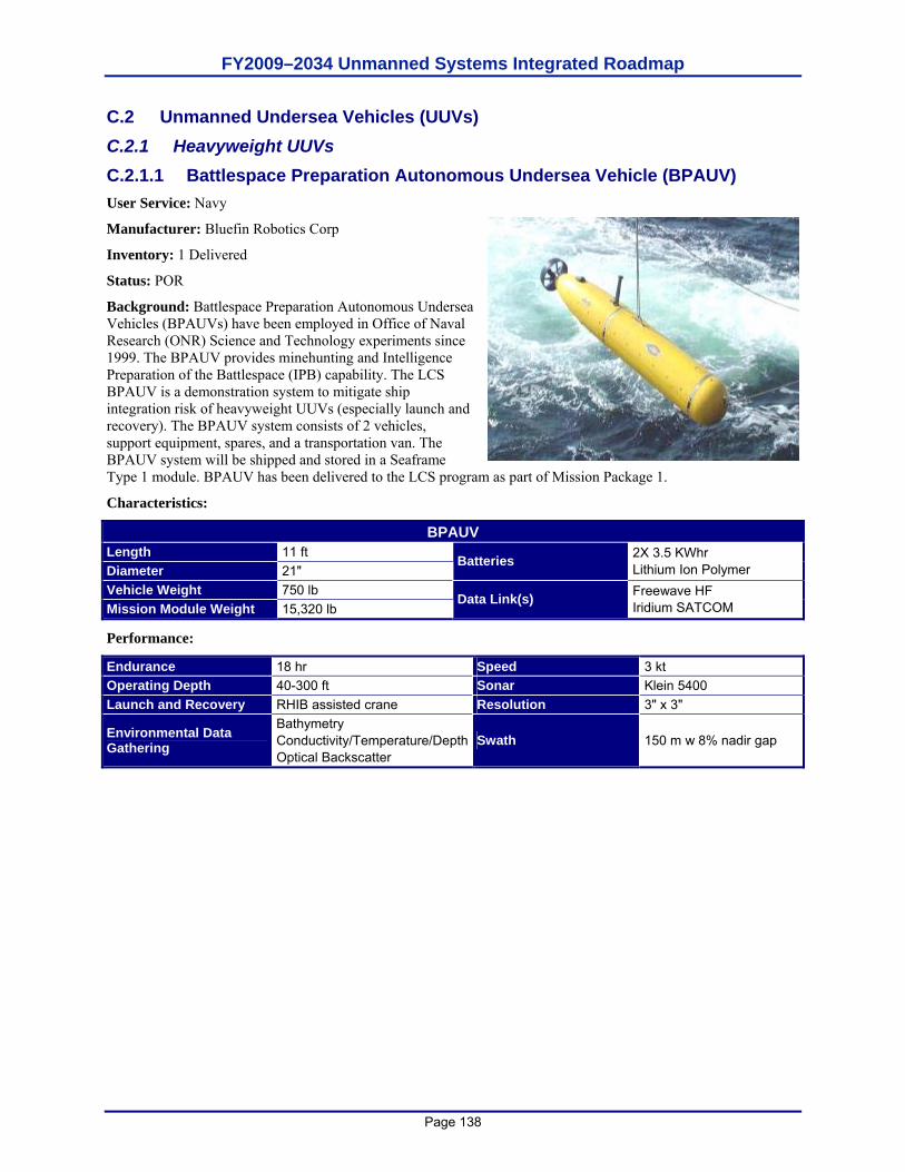
FY2009–2034 Unmanned Systems Integrated Roadmap
Page 138
C.2 Unmanned Undersea Vehicles (UUVs) C.2.1 Heavyweight UUVs C.2.1.1 Battlespace Preparation Autonomous Undersea Vehicle (BPAUV) User Service: Navy
Manufacturer: Bluefin Robotics Corp
Inventory: 1 Delivered
Status: POR
Background: Battlespace Preparation Autonomous Undersea Vehicles (BPAUVs) have been employed in Office of Naval Research (ONR) Science and Technology experiments since 1999. The BPAUV provides minehunting and Intelligence Preparation of the Battlespace (IPB) capability. The LCS BPAUV is a demonstration system to mitigate ship integration risk of heavyweight UUVs (especially launch and recovery). The BPAUV system consists of 2 vehicles, support equipment, spares, and a transportation van. The BPAUV system will be shipped and stored in a Seaframe Type 1 module. BPAUV has been delivered to the LCS program as part of Mission Package 1.
Characteristics:
BPAUV Length 11 ft Diameter 21"
Batteries 2X 3.5 KWhr Lithium Ion Polymer
Vehicle Weight 750 lb Mission Module Weight 15,320 lb
Data Link(s) Freewave HF Iridium SATCOM
Performance:
Endurance 18 hr Speed 3 kt Operating Depth 40-300 ft Sonar Klein 5400 Launch and Recovery RHIB assisted crane Resolution 3" x 3"
Environmental Data Gathering
Bathymetry Conductivity/Temperature/Depth Optical Backscatter
Swath 150 m w 8% nadir gap
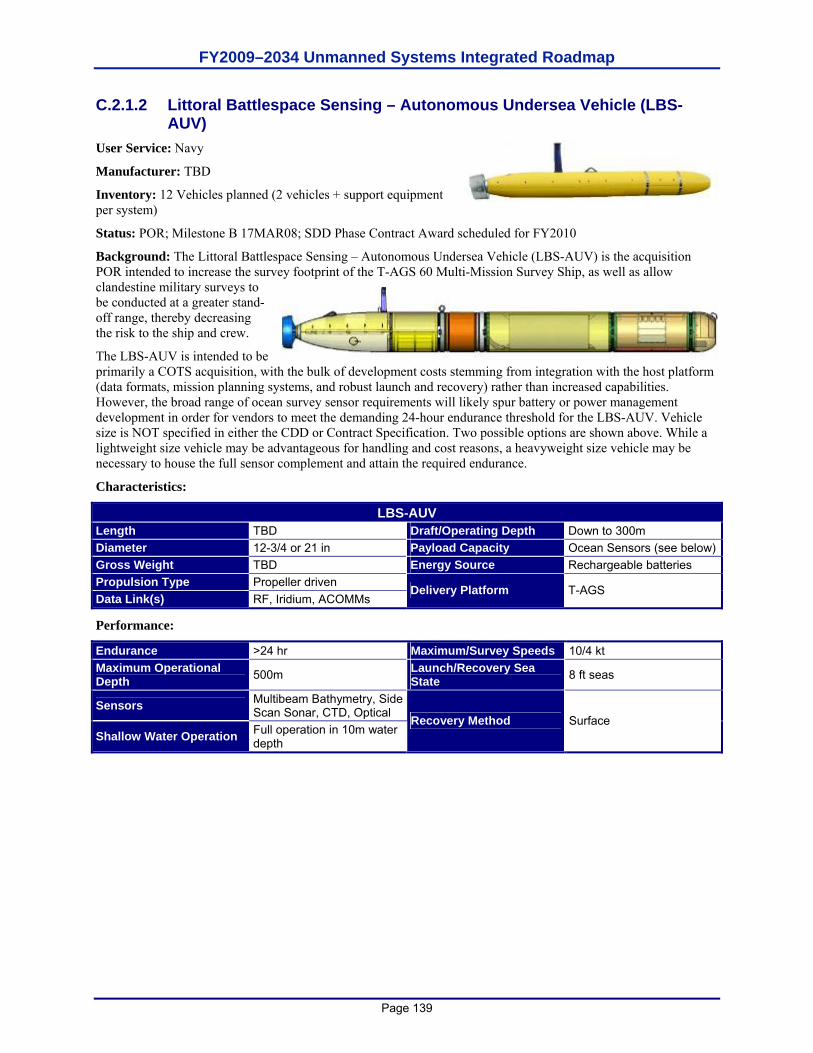
FY2009–2034 Unmanned Systems Integrated Roadmap
Page 139
C.2.1.2 Littoral Battlespace Sensing – Autonomous Undersea Vehicle (LBS-AUV)
User Service: Navy
Manufacturer: TBD
Inventory: 12 Vehicles planned (2 vehicles + support equipment per system)
Status: POR; Milestone B 17MAR08; SDD Phase Contract Award scheduled for FY2010
Background: The Littoral Battlespace Sensing – Autonomous Undersea Vehicle (LBS-AUV) is the acquisition POR intended to increase the survey footprint of the T-AGS 60 Multi-Mission Survey Ship, as well as allow clandestine military surveys to be conducted at a greater stand-off range, thereby decreasing the risk to the ship and crew.
The LBS-AUV is intended to be primarily a COTS acquisition, with the bulk of development costs stemming from integration with the host platform (data formats, mission planning systems, and robust launch and recovery) rather than increased capabilities. However, the broad range of ocean survey sensor requirements will likely spur battery or power management development in order for vendors to meet the demanding 24-hour endurance threshold for the LBS-AUV. Vehicle size is NOT specified in either the CDD or Contract Specification. Two possible options are shown above. While a lightweight size vehicle may be advantageous for handling and cost reasons, a heavyweight size vehicle may be necessary to house the full sensor complement and attain the required endurance.
Characteristics:
LBS-AUV Length TBD Draft/Operating Depth Down to 300m Diameter 12-3/4 or 21 in Payload Capacity Ocean Sensors (see below)Gross Weight TBD Energy Source Rechargeable batteries Propulsion Type Propeller driven Data Link(s) RF, Iridium, ACOMMs
Delivery Platform T-AGS
Performance:
Endurance >24 hr Maximum/Survey Speeds 10/4 kt Maximum Operational Depth 500m Launch/Recovery Sea
State 8 ft seas
Sensors Multibeam Bathymetry, Side Scan Sonar, CTD, Optical
Shallow Water Operation Full operation in 10m water depth
Recovery Method Surface
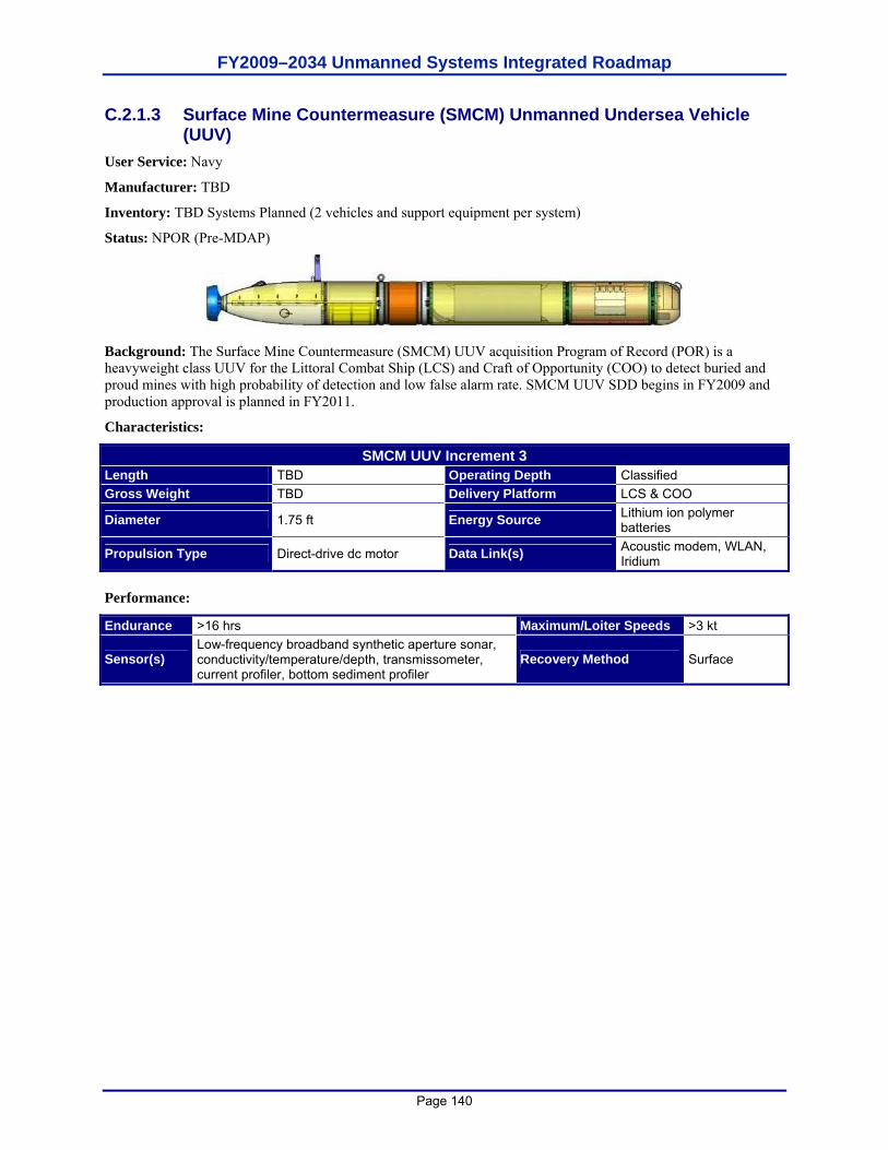
FY2009–2034 Unmanned Systems Integrated Roadmap
Page 140
C.2.1.3 Surface Mine Countermeasure (SMCM) Unmanned Undersea Vehicle (UUV)
User Service: Navy
Manufacturer: TBD
Inventory: TBD Systems Planned (2 vehicles and support equipment per system)
Status: NPOR (Pre-MDAP)
Background: The Surface Mine Countermeasure (SMCM) UUV acquisition Program of Record (POR) is a heavyweight class UUV for the Littoral Combat Ship (LCS) and Craft of Opportunity (COO) to detect buried and proud mines with high probability of detection and low false alarm rate. SMCM UUV SDD begins in FY2009 and production approval is planned in FY2011.
Characteristics:
SMCM UUV Increment 3 Length TBD Operating Depth Classified Gross Weight TBD Delivery Platform LCS & COO
Diameter 1.75 ft Energy Source Lithium ion polymer batteries
Propulsion Type Direct-drive dc motor Data Link(s) Acoustic modem, WLAN, Iridium
Performance:
Endurance >16 hrs Maximum/Loiter Speeds >3 kt
Sensor(s) Low-frequency broadband synthetic aperture sonar, conductivity/temperature/depth, transmissometer, current profiler, bottom sediment profiler
Recovery Method Surface
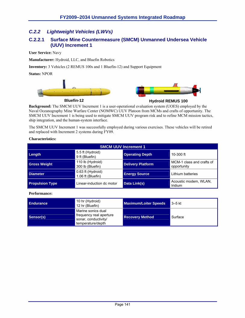
FY2009–2034 Unmanned Systems Integrated Roadmap
Page 141
C.2.2 Lightweight Vehicles (LWVs) C.2.2.1 Surface Mine Countermeasure (SMCM) Unmanned Undersea Vehicle
(UUV) Increment 1 User Service: Navy
Manufacturer: Hydroid, LLC, and Bluefin Robotics
Inventory: 3 Vehicles (2 REMUS 100s and 1 Bluefin-12) and Support Equipment
Status: NPOR
Bluefin-12
Hydroid REMUS 100
Background: The SMCM UUV Increment 1 is a user-operational evaluation system (UOES) employed by the Naval Oceanography Mine Warfare Center (NOMWC) UUV Platoon from MCMs and crafts of opportunity. The SMCM UUV Increment 1 is being used to mitigate SMCM UUV program risk and to refine MCM mission tactics, ship integration, and the human-system interface.
The SMCM UUV Increment 1 was successfully employed during various exercises. These vehicles will be retired and replaced with Increment 2 systems during FY09.
Characteristics:
SMCM UUV Increment 1
Length 5.5 ft (Hydroid) 9 ft (Bluefin) Operating Depth 10-300 ft
Gross Weight 110 lb (Hydroid) 300 lb (Bluefin) Delivery Platform MCM-1 class and crafts of
opportunity
Diameter 0.63 ft (Hydroid) 1.06 ft (Bluefin) Energy Source Lithium batteries
Propulsion Type Linear-induction dc motor Data Link(s) Acoustic modem, WLAN, Iridium
Performance:
Endurance 10 hr (Hydroid) 12 hr (Bluefin) Maximum/Loiter Speeds 3–5 kt
Sensor(s) Marine sonics dual frequency real aperture sonar, conductivity/ temperature/depth
Recovery Method Surface
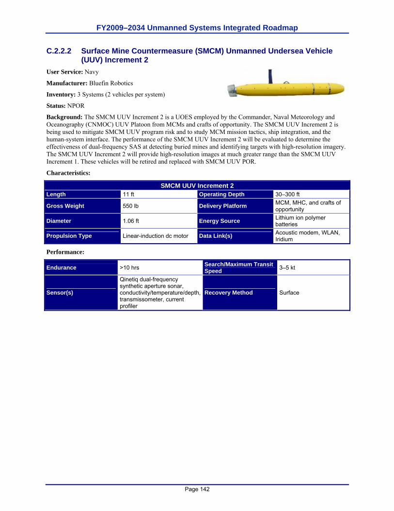
FY2009–2034 Unmanned Systems Integrated Roadmap
Page 142
C.2.2.2 Surface Mine Countermeasure (SMCM) Unmanned Undersea Vehicle (UUV) Increment 2
User Service: Navy
Manufacturer: Bluefin Robotics
Inventory: 3 Systems (2 vehicles per system)
Status: NPOR
Background: The SMCM UUV Increment 2 is a UOES employed by the Commander, Naval Meteorology and Oceanography (CNMOC) UUV Platoon from MCMs and crafts of opportunity. The SMCM UUV Increment 2 is being used to mitigate SMCM UUV program risk and to study MCM mission tactics, ship integration, and the human-system interface. The performance of the SMCM UUV Increment 2 will be evaluated to determine the effectiveness of dual-frequency SAS at detecting buried mines and identifying targets with high-resolution imagery. The SMCM UUV Increment 2 will provide high-resolution images at much greater range than the SMCM UUV Increment 1. These vehicles will be retired and replaced with SMCM UUV POR.
Characteristics:
SMCM UUV Increment 2 Length 11 ft Operating Depth 30–300 ft
Gross Weight 550 lb Delivery Platform MCM, MHC, and crafts of opportunity
Diameter 1.06 ft Energy Source Lithium ion polymer batteries
Propulsion Type Linear-induction dc motor Data Link(s) Acoustic modem, WLAN, Iridium
Performance:
Endurance >10 hrs Search/Maximum Transit Speed 3–5 kt
Sensor(s)
Qinetiq dual-frequency synthetic aperture sonar, conductivity/temperature/depth, transmissometer, current profiler
Recovery Method Surface
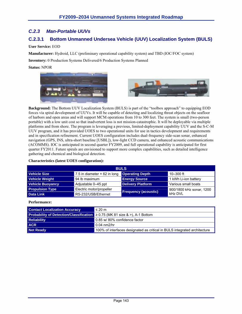
FY2009–2034 Unmanned Systems Integrated Roadmap
Page 143
C.2.3 Man-Portable UUVs C.2.3.1 Bottom Unmanned Undersea Vehicle (UUV) Localization System (BULS) User Service: EOD
Manufacturer: Hydroid, LLC (preliminary operational capability system) and TBD (IOC/FOC system)
Inventory: 0 Production Systems Delivered/6 Production Systems Planned
Status: NPOR
Background: The Bottom UUV Localization System (BULS) is part of the “toolbox approach” to equipping EOD forces via spiral development of UUVs. It will be capable of detecting and localizing threat objects on the seafloor of harbors and open areas and will support MCM operations from 10 to 300 feet. The system is small (two-person portable) with a low unit cost so that inadvertent loss is not mission-catastrophic. It will be deployable via multiple platforms and from shore. The program is leveraging a previous, limited-deployment capability UUV and the S-C-M UUV program, and it has provided UOES to two operational units for use in tactics development and requirements and in specification refinement. Current UOES configuration includes dual-frequency side-scan sonar, enhanced navigation (GPS, INS, ultra-short baseline [USBL]), low-light CCD camera, and enhanced acoustic communications (ACOMMS). IOC is anticipated in second quarter FY2009, and full operational capability is anticipated for first quarter FY2011. Future spirals are envisioned to support more complex capabilities, such as detailed intelligence gathering and chemical and biological detection.
Characteristics (latest UOES configuration):
BULS Vehicle Size 7.5 in diameter × 62 in long Operating Depth 10–300 ft Vehicle Weight 94 lb maximum Energy Source 1 kWh Li-ion battery Vehicle Buoyancy Adjustable 0–45 ppt Delivery Platform Various small boats Propulsion Type Electric motor/propeller Data Link RS-232/USB/Ethernet
Frequency (acoustic) 900/1800 kHz sonar, 1200 kHz DVL
Performance:
Contact Localization Accuracy ≤ 20 m Probability of Detection/Classification ≥ 0.75 (MK 81 size & >), A-1 Bottom Reliability 0.85 w/ 80% confidence factor ACR 0.04 nm2/hr Net Ready 100% of interfaces designated as critical in BULS integrated architecture
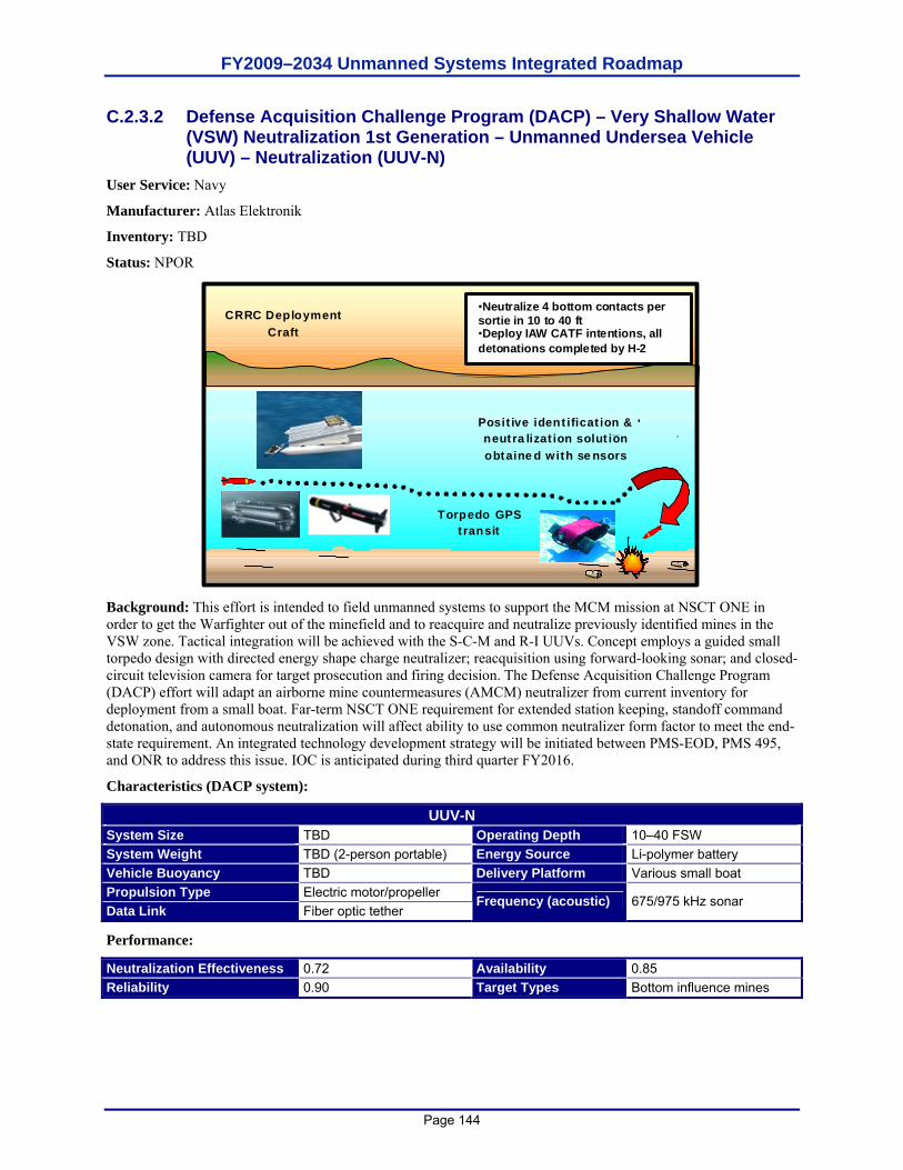
FY2009–2034 Unmanned Systems Integrated Roadmap
Page 144
C.2.3.2 Defense Acquisition Challenge Program (DACP) – Very Shallow Water (VSW) Neutralization 1st Generation – Unmanned Undersea Vehicle (UUV) – Neutralization (UUV-N)
User Service: Navy
Manufacturer: Atlas Elektronik
Inventory: TBD
Status: NPOR
CRRC Deployment Craft
Torpedo GPS transit
Positive identification & neutralization solution obtained with sensors
•Neutralize 4 bottom contacts per sortie in 10 to 40 ft •Deploy IAW CATF intentions, all detonations completed by H-2
Background: This effort is intended to field unmanned systems to support the MCM mission at NSCT ONE in order to get the Warfighter out of the minefield and to reacquire and neutralize previously identified mines in the VSW zone. Tactical integration will be achieved with the S-C-M and R-I UUVs. Concept employs a guided small torpedo design with directed energy shape charge neutralizer; reacquisition using forward-looking sonar; and closed-circuit television camera for target prosecution and firing decision. The Defense Acquisition Challenge Program (DACP) effort will adapt an airborne mine countermeasures (AMCM) neutralizer from current inventory for deployment from a small boat. Far-term NSCT ONE requirement for extended station keeping, standoff command detonation, and autonomous neutralization will affect ability to use common neutralizer form factor to meet the end-state requirement. An integrated technology development strategy will be initiated between PMS-EOD, PMS 495, and ONR to address this issue. IOC is anticipated during third quarter FY2016.
Characteristics (DACP system):
UUV-N System Size TBD Operating Depth 10–40 FSW System Weight TBD (2-person portable) Energy Source Li-polymer battery Vehicle Buoyancy TBD Delivery Platform Various small boat Propulsion Type Electric motor/propeller Data Link Fiber optic tether
Frequency (acoustic) 675/975 kHz sonar
Performance:
Neutralization Effectiveness 0.72 Availability 0.85 Reliability 0.90 Target Types Bottom influence mines
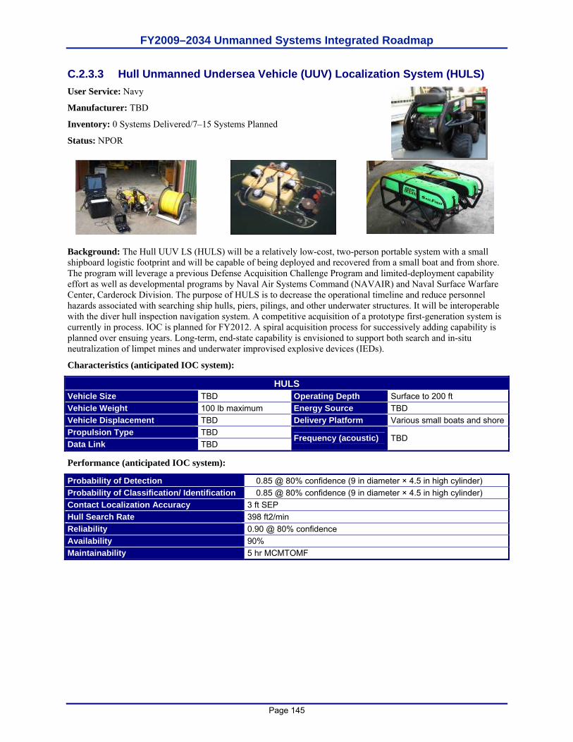
FY2009–2034 Unmanned Systems Integrated Roadmap
Page 145
C.2.3.3 Hull Unmanned Undersea Vehicle (UUV) Localization System (HULS) User Service: Navy
Manufacturer: TBD
Inventory: 0 Systems Delivered/7–15 Systems Planned
Status: NPOR
Background: The Hull UUV LS (HULS) will be a relatively low-cost, two-person portable system with a small shipboard logistic footprint and will be capable of being deployed and recovered from a small boat and from shore. The program will leverage a previous Defense Acquisition Challenge Program and limited-deployment capability effort as well as developmental programs by Naval Air Systems Command (NAVAIR) and Naval Surface Warfare Center, Carderock Division. The purpose of HULS is to decrease the operational timeline and reduce personnel hazards associated with searching ship hulls, piers, pilings, and other underwater structures. It will be interoperable with the diver hull inspection navigation system. A competitive acquisition of a prototype first-generation system is currently in process. IOC is planned for FY2012. A spiral acquisition process for successively adding capability is planned over ensuing years. Long-term, end-state capability is envisioned to support both search and in-situ neutralization of limpet mines and underwater improvised explosive devices (IEDs).
Characteristics (anticipated IOC system):
HULS Vehicle Size TBD Operating Depth Surface to 200 ft Vehicle Weight 100 lb maximum Energy Source TBD Vehicle Displacement TBD Delivery Platform Various small boats and shorePropulsion Type TBD Data Link TBD
Frequency (acoustic) TBD
Performance (anticipated IOC system):
Probability of Detection � 0.85 @ 80% confidence (9 in diameter × 4.5 in high cylinder) Probability of Classification/ Identification � 0.85 @ 80% confidence (9 in diameter × 4.5 in high cylinder) Contact Localization Accuracy 3 ft SEP Hull Search Rate 398 ft2/min Reliability 0.90 @ 80% confidence Availability 90% Maintainability 5 hr MCMTOMF
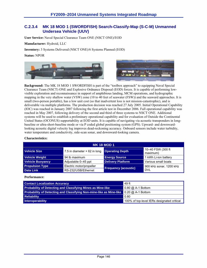
FY2009–2034 Unmanned Systems Integrated Roadmap
Page 146
C.2.3.4 MK 18 MOD 1 (SWORDFISH) Search-Classify-Map (S-C-M) Unmanned Undersea Vehicle (UUV)
User Service: Naval Special Clearance Team ONE (NSCT ONE)/EOD
Manufacturer: Hydroid, LLC
Inventory: 3 Systems Delivered (NSCT ONE)/6 Systems Planned (EOD)
Status: NPOR
Background: The MK 18 MOD 1 SWORDFISH is part of the “toolbox approach” to equipping Naval Special Clearance Team (NSCT) ONE and Explosive Ordnance Disposal (EOD) forces. It is capable of performing low-visible exploration and reconnaissance in support of amphibious landing, MCM operations, and hydrographic mapping in the very shallow water (VSW) zone (10 to 40 feet of seawater (FSW)) and the seaward approaches. It is small (two-person portable), has a low unit cost (so that inadvertent loss is not mission-catastrophic), and is deliverable via multiple platforms. The production decision was reached 27 July 2005. Initial Operational Capability (IOC) was reached in January 2007 following the first article test in December 2006. Full operational capability was reached in May 2007, following delivery of the second and third of three systems to NSCT ONE. Additional systems will be used to establish a preliminary operational capability and for evaluation of Outside the Continental United States (OCONUS) supportability at EOD units. It is capable of navigating via acoustic transponders in long-baseline or ultra-short-baseline mode or via P coded global positioning system (GPS). Upward- and downward-looking acoustic digital velocity log improves dead-reckoning accuracy. Onboard sensors include water turbidity, water temperature and conductivity, side-scan sonar, and downward-looking camera.
Characteristics:
MK 18 MOD 1
Vehicle Size 7.5 in diameter × 62 in long Operating Depth 10–40 FSW (300 ft maximum)
Vehicle Weight 94 lb maximum Energy Source 1 kWh Li-ion battery Vehicle Buoyancy Adjustable 0–45 ppt Delivery Platform Various small boats Propulsion Type Electric motor/propeller Data Link RS-232/USB/Ethernet
Frequency (acoustic) 900 kHz sonar, 1200 kHz DVL
Performance:
Contact Localization Accuracy 49 ft Probability of Detecting and Classifying Mines as Mine-like 0.80 @ A-1 Bottom Probability of Detecting and Classifying Non-mine-like as Mine-like 0.20 @ A-1 Bottom Reliability 0.80 Interoperability 100% of top-level IERs designated critical
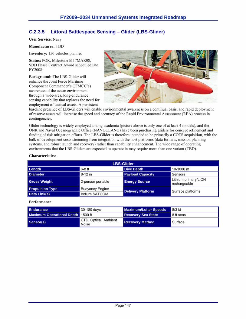
FY2009–2034 Unmanned Systems Integrated Roadmap
Page 147
C.2.3.5 Littoral Battlespace Sensing – Glider (LBS-Glider) User Service: Navy
Manufacturer: TBD
Inventory: 150 vehicles planned
Status: POR; Milestone B 17MAR08; SDD Phase Contract Award scheduled late FY2008
Background: The LBS-Glider will enhance the Joint Force Maritime Component Commander’s (JFMCC’s) awareness of the ocean environment through a wide-area, long-endurance sensing capability that replaces the need for employment of tactical assets. A persistent baseline presence of LBS-Gliders will enable environmental awareness on a continual basis, and rapid deployment of reserve assets will increase the speed and accuracy of the Rapid Environmental Assessment (REA) process in contingencies.
Glider technology is widely employed among academia (picture above is only one of at least 4 models), and the ONR and Naval Oceanographic Office (NAVOCEANO) have been purchasing gliders for concept refinement and funding of risk mitigation efforts. The LBS-Glider is therefore intended to be primarily a COTS acquisition, with the bulk of development costs stemming from integration with the host platforms (data formats, mission planning systems, and robust launch and recovery) rather than capability enhancement. The wide range of operating environments that the LBS-Gliders are expected to operate in may require more than one variant (TBD).
Characteristics:
LBS-Glider Length 6-8 ft Dive Depth 10-1000 m Diameter 8-12 in Payload Capacity Sensors
Gross Weight 2-person portable Energy Source Lithium primary/LiON rechargeable
Propulsion Type Buoyancy Engine Data Link(s) Iridium SATCOM
Delivery Platform Surface platforms
Performance:
Endurance 30-180 days Maximum/Loiter Speeds 8/3 kt Maximum Operational Depth 1500 ft Recovery Sea State 8 ft seas
Sensor(s) CTD, Optical, Ambient Noise Recovery Method Surface
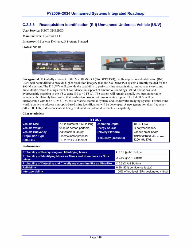
FY2009–2034 Unmanned Systems Integrated Roadmap
Page 148
C.2.3.6 Reacquisition-Identification (R-I) Unmanned Undersea Vehicle (UUV) User Service: NSCT ONE/EOD
Manufacturer: Hydroid, LLC
Inventory: 0 Systems Delivered/3 Systems Planned
Status: NPOR
Background: Potentially a variant of the MK 18 MOD 1 (SWORDFISH), the Reacquisition-Identification (R-I) UUV will be modified to provide higher resolution imagery than the SWORDFISH system currently fielded for the S-C-M mission. The R I UUV will provide the capability to perform mine reacquisition, limited area search, and mine identification to a high level of confidence, in support of amphibious landings, MCM operations, and hydrographic mapping in the VSW zone (10 to 40 FSW). The system will remain a small, two-person portable vehicle with relatively low cost so that inadvertent loss is not mission-catastrophic. The R-I UUV will be interoperable with the S-C-M UUV, MK 8 Marine Mammal System, and Underwater Imaging System. Formal mine warfare tactics to address non-optic-based mine identification will be developed. A new generation dual-frequency (900/1800 kHz) side-scan sonar is being evaluated for potential to reach R-I capability.
Characteristics:
R-I UUV Vehicle Size 7.5 in diameter × 62 in long Operating Depth 10–40 FSW Vehicle Weight 94 lb (2-person portable) Energy Source Li-polymer battery Vehicle Buoyancy Adjustable 0–45 ppt Delivery Platform Various small boats Propulsion Type Electric motor/propeller Data Link RS-232/USB/Ethernet
Frequency (acoustic) TBD900/1800 kHz sonar 1200 kHz DVL
Performance:
Probability of Reacquiring and Identifying Mines ≥ 0.85 @ A-1 Bottom Probability of Identifying Mines as Mines and Non-mines as Non-mines ≥ 0.80 @ A-1 Bottom
Probability of Detecting and Classifying Non-mine-like as Mine-like ≤ 0.2 @ A-1 Bottom Reliability 0.90 (80% confidence factor) Interoperability 100% of top-level IERs designated critical

FY2009–2034 Unmanned Systems Integrated Roadmap
Page 149
This page is intentionally left blank.
FY2009–2034 Unmanned Systems Integrated Roadmap
Page 150
APPENDIX D. TECHNOLOGY ENABLER DATA SHEETS D.1 3D World Modeling A. Narrative Describing Effort: 3D world modeling for either navigation/mission planning or manipulation (but
not both, since they are at different resolutions and using different techniques for representation). This includes outdoor and indoor models but is not referenced to each. Models are of sufficient resolution to perform navigation, planning and manipulation tasks and are textured with color images.
B. Capability Supported: Force Application, Battlespace Awareness
C. Performance Attributes: Enough resolution and accuracy to enable autonomous robot navigation or remote teleoperation.
D. Current or Future Acquisition Program(s) Supported: TBD
E. Technology Readiness Levels by Year: For industrial manipulation in fixed environments: TRL 9 currently:
For UAS: FY09 - TRL 8-9 For UGVs: FY09 - TRL 4-6; FY10 - TRL 5-7; FY11 - TRL 6-8
D.2 Active Signature Management A. Narrative Describing Effort: Develop technologies that would support actively managing RF signature in
response to environmental queues. Signature management might be through shape/form shifting, deceptive radio frequency (RF) emissions, or other technologies.
B. Capability Supported: Battlespace Awareness, Force Application, Protection
C. Performance Attributes: Ingress and egress undetected from low, medium, and high-threat environments
D. Current or Future Acquisition Program(s) Supported: TBD
E. Technology Readiness Levels by Year: 2009 – TRL 1; 2034 - TRL 6
D.3 Architecture Proprietary A. Narrative Describing Effort: Continue to develop and refine interface architectures and standards defining the
format and content of information (e.g. messages) passing between unmanned systems elements.
B. Capability Supported: All JCAs, including Force Application, Command & Control, Battlespace Awareness, Net-Centric, Building Partnerships, Protection, Force Support, Logistics, and Corporate Mgmt & Support.
C. Performance Attributes: As a message standard, JAUS does not have a measurable performance.
D. Current or Future Acquisition Program(s) Supported: To date, FCS (all UAS and UGV), USSV, AEODRS, MTRS, Gladiator TUGV, ARTS.
E. Technology Readiness Levels by Year: The current architecture (JAUS) is used in systems today. The TRL of any developments and/or refinements of existing or future architectures is TBD.
D.4 Artificial Muscle Systems A. Narrative Describing Effort: Develop actuation technologies based conceptually on human muscle that
provide high actuation forces, compliance, and integrated force and strain sensing. The actuators would be used as the foundation of high performance anthropomorphic mobility and manipulation systems for UGVs.
B. Capability Supported: Protection, Battlespace Awareness, Building Partnerships
C. Performance Attributes: High actuation forces and speeds; integrated force and strain sensing; multiple degrees of freedom of motion; integrated and robust control electronics; scalable
FY2009–2034 Unmanned Systems Integrated Roadmap
Page 151
D. Current or Future Acquisition Program(s) Supported: AEODRS
E. Technology Readiness Levels by Year: FY09 - TRL 3
D.5 Automatically Deployed Communication Relays A. Narrative Describing Effort: RF relay “bricks” are automatically launched from a moving ground robot where
needed to extend the link between the robot and its remote control station. The robot, control station, and relay nodes form a mesh network.
B. Capability Supported: Force Application, Battlespace Awareness, Net-Centric
C. Performance Attributes: Bandwidth capable of carrying two real-time video channels.
D. Current or Future Acquisition Program(s) Supported: MTRS
E. Technology Readiness Levels by Year: FY09 - TRL 7; FY10 - TRL 8; FY11 - TRL 9
D.6 Autonomous Robotic Capability Suite (ARCS) A. Narrative Describing Effort: The Autonomous Robotic Capability Suite (ARCS) program addresses a USA
Engineering requirement to provide a multifunctional robotic capability using fielded small robotic systems while demonstrating system collaboration. Today’s robots cannot adaptively seek, automatically map or provide the dexterity or mobility to address complex hazards. The overarching goal of the ARCS effort is to provide intelligent, mission centric payloads that transform existing robots into effective threat identification, characterization, and mapping systems. The ARCS program will develop plug and play payloads for multiple missions (e.g., CBRN, IED, and human detection). For an initial use case, ARCS will focus on the need to search for, detect, and mark different types of buried landmines in various terrains with flexible autonomy by developing portable, reconfigurable unmanned system behaviors. After the initial experiment, to be completed in FY08, ARCS will expand the behaviors developed for countermine to other Maneuver and Maneuver Support functions. So far, chemical detection, radiological assessment and explosive hazard detection have also been demonstrated in addition to the countermine mission. These behaviors are implemented on small unmanned ground vehicles integrating robust mission-centric payloads as well as sensors for navigation, mapping, path planning and obstacle avoidance. Under the ARCS project, several platforms have been selected to demonstrate robotic countermine and CBRN capability including two fielded robotic systems. It is the intent of this program to develop behaviors plug and played on other unmanned systems with minor configuration changes. This program will consist of two demonstrations and one final experiment designed to leverage off maturing work and will ensure developed behaviors can fit well within, and benefit from, a larger system of systems.
B. Capability Supported (Payoff): This applies to command and control, force support, and protection. Support of JGR Technology Matrix: Interface Technologies: Organic tasking tools such as hand-held controllers for proximal interaction on the
move to task manage and control multiple UAS and UGVs to collaboratively conduct specified missions. Autonomous Technologies: Provides small-scale, inexpensive autonomy payloads imbedded with sensor
based tactical behaviors to achieve collaborative threat seeking capabilities. Sensors-Perception for UAS and UGV navigation, collaborative behaviors and explosive hazard detection. Seamless positioning for UAS and UGV navigation, such that UAS and UGVs can support one another in
the case of communications and positioning failures Path Planning for the UAS to UGV to plan and execute a path to a sensor designated point on the ground. Local common operating picture tools that use common reference points and environmental features to
support mission planning. Cooperative behaviors to search for, detect, report and mark CM and CBRN and explosive hazards.
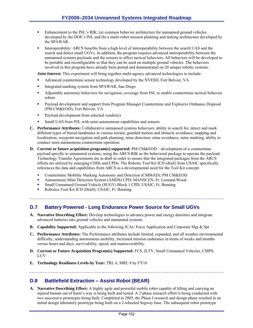
FY2009–2034 Unmanned Systems Integrated Roadmap
Page 152
Enhancement to the INL’s RIK: (a) common behavior architecture for unmanned ground vehicles developed by the DOE’s INL and (b) a multi-robot mission planning and tasking architecture developed by the SPAWAR.
Interoperability: ARCS benefits from a high level of interoperability between the search UAS and the search and detect small UGVs. In addition, the program requires advanced interoperability between the unmanned systems payloads and the sensors to affect tactical behaviors. All behaviors will be developed to be portable and reconfigurable so that they can be used on multiple ground vehicles. The behaviors involved in this program have already been ported and demonstrated on 20 unique robotic systems.
Joint Interest: This experiment will bring together multi-agency advanced technologies to include: Advanced countermine sensor technology developed by the NVESD, Fort Belvoir, VA Integrated marking system from SPAWAR, San Diego Adjustable autonomy behaviors for navigation, coverage from INL to enable countermine tactical behavior
robots Payload development and support from Program Manager Countermine and Explosive Ordnance Disposal
(PM CM&EOD), Fort Belvoir, VA Payload development from selected vendor(s) Small UAS from INL with semi-autonomous capabilities and sensors
C. Performance Attributes: Collaborative unmanned systems behaviors; ability to search for, detect and mark different types of buried landmines in various terrain; guarded motion and obstacle avoidance; mapping and localization; waypoint navigation and path planning; mine detection; mine avoidance; mine marking; ability to conduct semi-autonomous countermine operation.
D. Current or future acquisition program(s) supported: PM CM&EOD – development of a countermine payload specific to unmanned systems, using the ARCS RIK as the behavioral package to operate the payload. Technology Transfer Agreements are in draft in order to ensure that the integrated packages from the ARCS efforts are utilized by emerging CDDs and CPDs. The Robotic Tool Kit ICD (draft) from USAIC specifically references the data and capabilities from ARCS as a developmental need for the Tool Kit concept.
Countermine Mobility Marking Autonomy and Detection (CMMAD); PM CM&EOD Autonomous Mine Detection System (AMDS) CPD; MANSCEN, Ft. Leonard-Wood Small Unmanned Ground Vehicle (SUGV) Block 1 CPD; USAIC, Ft. Benning Robotics Tool Kit ICD (Draft); USAIC, Ft. Benning
D.7 Battery Powered - Long Endurance Power Source for Small UGVs A. Narrative Describing Effort: Develop technologies to advance power and energy densities and integrate
advanced batteries into ground vehicles and unmanned systems.
B. Capability Supported: Applicable to the following JCAs: Force Application and Corporate Mgt & Spt
C. Performance Attributes: The Performance attributes include limited, expanded, and all weather environmental difficulty, understanding autonomous mobility, increased mission endurance in terms of weeks and months versus hours and days, survivability, speed, and maneuverability.
D. Current or Future Acquisition Program(s) Supported: FCS, JLTV, Small Unmanned Vehicles, CMPS, LUV
E. Technology Readiness Levels by Year: TRL 6, MRL 8 by FY10
D.8 Battlefield Extraction – Assist Robot (BEAR) A. Narrative Describing Effort: A highly agile and powerful mobile robot capable of lifting and carrying an
injured human out of harm’s way is being built and tested. A 2-phase research effort is being conducted with two successive prototypes being built. Completed in 2005, the Phase I research and design phase resulted in an initial design laboratory prototype being built on a 2-wheeled Segway base. The subsequent robot prototype
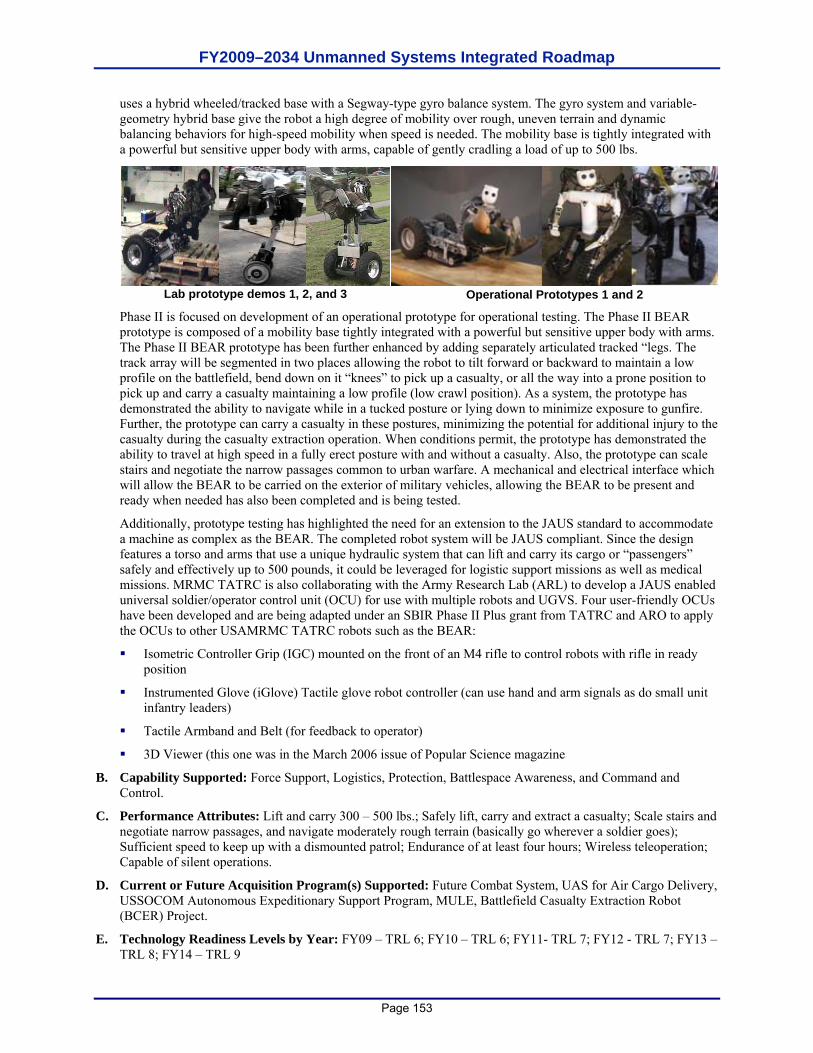
FY2009–2034 Unmanned Systems Integrated Roadmap
Page 153
uses a hybrid wheeled/tracked base with a Segway-type gyro balance system. The gyro system and variable-geometry hybrid base give the robot a high degree of mobility over rough, uneven terrain and dynamic balancing behaviors for high-speed mobility when speed is needed. The mobility base is tightly integrated with a powerful but sensitive upper body with arms, capable of gently cradling a load of up to 500 lbs.
Lab prototype demos 1, 2, and 3 Operational Prototypes 1 and 2
Phase II is focused on development of an operational prototype for operational testing. The Phase II BEAR prototype is composed of a mobility base tightly integrated with a powerful but sensitive upper body with arms. The Phase II BEAR prototype has been further enhanced by adding separately articulated tracked “legs. The track array will be segmented in two places allowing the robot to tilt forward or backward to maintain a low profile on the battlefield, bend down on it “knees” to pick up a casualty, or all the way into a prone position to pick up and carry a casualty maintaining a low profile (low crawl position). As a system, the prototype has demonstrated the ability to navigate while in a tucked posture or lying down to minimize exposure to gunfire. Further, the prototype can carry a casualty in these postures, minimizing the potential for additional injury to the casualty during the casualty extraction operation. When conditions permit, the prototype has demonstrated the ability to travel at high speed in a fully erect posture with and without a casualty. Also, the prototype can scale stairs and negotiate the narrow passages common to urban warfare. A mechanical and electrical interface which will allow the BEAR to be carried on the exterior of military vehicles, allowing the BEAR to be present and ready when needed has also been completed and is being tested.
Additionally, prototype testing has highlighted the need for an extension to the JAUS standard to accommodate a machine as complex as the BEAR. The completed robot system will be JAUS compliant. Since the design features a torso and arms that use a unique hydraulic system that can lift and carry its cargo or “passengers” safely and effectively up to 500 pounds, it could be leveraged for logistic support missions as well as medical missions. MRMC TATRC is also collaborating with the Army Research Lab (ARL) to develop a JAUS enabled universal soldier/operator control unit (OCU) for use with multiple robots and UGVS. Four user-friendly OCUs have been developed and are being adapted under an SBIR Phase II Plus grant from TATRC and ARO to apply the OCUs to other USAMRMC TATRC robots such as the BEAR:
Isometric Controller Grip (IGC) mounted on the front of an M4 rifle to control robots with rifle in ready position
Instrumented Glove (iGlove) Tactile glove robot controller (can use hand and arm signals as do small unit infantry leaders)
Tactile Armband and Belt (for feedback to operator)
3D Viewer (this one was in the March 2006 issue of Popular Science magazine
B. Capability Supported: Force Support, Logistics, Protection, Battlespace Awareness, and Command and Control.
C. Performance Attributes: Lift and carry 300 – 500 lbs.; Safely lift, carry and extract a casualty; Scale stairs and negotiate narrow passages, and navigate moderately rough terrain (basically go wherever a soldier goes); Sufficient speed to keep up with a dismounted patrol; Endurance of at least four hours; Wireless teleoperation; Capable of silent operations.
D. Current or Future Acquisition Program(s) Supported: Future Combat System, UAS for Air Cargo Delivery, USSOCOM Autonomous Expeditionary Support Program, MULE, Battlefield Casualty Extraction Robot (BCER) Project.
E. Technology Readiness Levels by Year: FY09 – TRL 6; FY10 – TRL 6; FY11- TRL 7; FY12 - TRL 7; FY13 – TRL 8; FY14 – TRL 9
FY2009–2034 Unmanned Systems Integrated Roadmap
Page 154
D.9 Bio-mass Reactor Power A. Narrative Describing Effort: Develop technologies to support bio-mass reactors to provide electrical power.
The ability to use bio-mass would allow an unmanned system to increase its mission endurance and increase its covert advantages by “living off the land.” The ideal bio-mass reactor would allow the unmanned systems to convert prepared food stuffs as well as raw foods and natural bio-mass.
B. Capability Supported: Battlespace Awareness, Building Partnerships, Force Application, Force Support, Protection
C. Performance Attributes: Mission endurance in months
D. Current or Future Acquisition Program(s) Supported: TBD
E. Technology Readiness Levels by Year: 2009 – TRL 2; 2034 – TRL 6
D.10 Biomimetic Human Detection A. Narrative Describing Effort: Human detection based on emulation of biological sensors, including visual,
aural, and olfactory.
B. Capability Supported: Force Application, Battlespace Awareness
C. Performance Attributes: Detection of humans as well as a dog can.
D. Current or Future Acquisition Program(s) Supported: TBD
E. Technology Readiness Levels by Year: TBD
D.11 BioRobotics A. Narrative Describing Effort: The BioRobotics (formerly Biodynotics) program will increase the capabilities
of military robots by applying dynamics and control based on biological inspired models. A specific objective is to develop and transition a tetrapod robot that can carry loads in the tactical environment.
B. Capability Supported: Force Application – Maneuver
C. Performance Attributes: Individual System; Spectrum Independent – Frequency Hopping; Obstacle Avoidance; Operation in Expanded Environmental Difficulty; Product Line Independent; OPSEC – Signature Low; Operational Control ratio of 1:1
D. Current or Future Acquisition Program(s) Supported: None
E. Technology Readiness Levels by Year: 2008 – TRL 6
D.12 Bird Dog/Warfighter’s Associate A. Narrative Describing Effort: The robot will possess empathy with the human operator, and will be able to take
high-level commands from the operator much as a bird dog does from the hunter. Commands may be verbal or by hand gestures. The robot will be aware of its environment and the operator’s mental and physiological status, and uses these cues to assist its interpretation of the verbal and gesture commands. The robot acts more like a partner or associate of the Warfighter. Sensor outputs from Future Force Warrior technologies will contribute much to the robot’s awareness.
B. Capability Supported: Force Application, Battlespace Awareness C. Performance Attributes: Environmental awareness; Human detection and tracking D. Current or Future Acquisition Program(s) Supported: Future Force Warrior
FY2009–2034 Unmanned Systems Integrated Roadmap
Page 155
E. Technology Readiness Levels by Year: FY09 – TRL 4; FY10 - TRL 5; FY12 - TRL 7; FY15 – TRL 8 D.13 CENTAUR Ground Mobility System
A. Narrative Describing Effort: CENTAUR Ground Mobility System is a concept and technology feasibility effort to integrate the Battlefield Extraction – Assist Robot (BEAR) head (including sensors) and upper torso, and the BIG DOG quadruped robot. CENTAUR combines the best attributes of each system: BEAR – Sensors and Upper Torso Flexibility, Maneuverability, Grasping and Strength; and BIG DOG – Mobility over various terrains, including rough terrain.
CENTAUR Components: Big Dog Quadruped Robot & BEAR Head and Upper Torso
B. Capability Supported: Force Support, Logistics, Protection, Battlespace Awareness, Force Application, & Command and Control
C. Performance Attributes: Initially teleoperation (wireless), but the object systems should be autonomous; Lift and carry 300 – 500 lbs.; Safely lift, carry and extract a casualty; Scale stairs and negotiate narrow passages, and navigate rough terrain (basically go wherever a soldier goes); Sufficient speed to keep up with a dismounted patrol; Endurance of at least four hours; Capable of silent operations.
D. Current or Future Acquisition Programs Supported: Future Combat System, Maritime Force 2025, UAS for Air Cargo Delivery, USSOCOM Autonomous Expeditionary Support Program (AESP), Battlefield Casualty Extraction Robot (BCER) Project
E. Technology Readiness Levels By Year: FY09 - TRL 4; FY10 - TRL 5; FY11 - TRL 5; FY12 - TRL 6; FY13 - TRL 6; FY14 - TRL 7
D.14 Chemical Robots (ChemBots) A. Narrative Describing Effort: The Chemical Robots (ChemBots) program is developing soft, flexible, mobile
objects that can identify and maneuver through openings smaller than their static structural dimensions and restore their size, shape, and functionality afterwards; carry meaningful payloads; and perform tasks. ChemBots represent the convergence of soft materials chemistry and robotics to create a fundamentally new class of soft, meso-scale robots.
B. Capability Supported (Payoff): Force Application, Battlespace Awareness, Protection C. Performance Attributes: Adaptive Tactical Behaviors, Expanded Environmental Difficulty, Mission
Endurance in days D. Current or Future Acquisition Program(s) Supported: TBD E. Technology Readiness Levels by Year: FY09 – TRL 3; FY10 – TRL 4; FY11 – TRL 6; FY12 – TRL 7
FY2009–2034 Unmanned Systems Integrated Roadmap
Page 156
D.15 Collaborative Networked Autonomous Vehicles (CNAV) A. Narrative Describing Effort: The Collaborative Networked Autonomous Vehicles (CNAV) program will
create a field of dozens or hundreds of networked unmanned undersea vehicles, connected by wireless acoustic communications, that will work collaboratively and autonomously to detect, classify, and localize target vehicles transiting the field.
B. Capability Supported: Force Application, Command and Control, Battlespace Awareness, and Net-Centric C. Performance Attributes: Mission Endurance in Weeks; Operational Control 1:# within Domain D. Current or Future Acquisition Program(s) Supported: OPNAV-N87 and NAVSEA (PEO-IWS) E. Technology Readiness Levels by Year: 2009 - TRL 6 D.16 Communications/Navigation Network Node (CN3) A. Narrative Describing Effort: Unmanned undersea vehicles (UUVs) can serve as critical communication and
navigation links between various platforms—at sea, on shore, even into the air and space realms. As with the other missions, they can be operated from a variety of platforms, at long standoff distances, and for extended periods of time. A small vehicle can function as an information conduit between a subsea platform and an array, or it can clandestinely come to the surface and provide a discreet antenna. As an aid to navigation, UUVs can serve as stand-by buoys, positioning themselves at designated locations and popping to the surface to provide visual or other references for military maneuvers or other operations. UUVs can also provide the link between subsurface platforms and GPS or other navigation system, without exposing the platform to unnecessary risk. Prepositioned beacons could be placed to provide navigational references in circumstances where conventional means are not available or desirable for use.
B. Capability Supported: Battlespace Awareness; Net-centric C. Performance Attributes: Bandwidth; Teaming Within Domain D. Current or Future Acquisition Program(s) Supported: TBD E. Technology Readiness Levels by Year: TBD D.17 Complex Terrain Mobility A. Narrative Describing Effort: Develop technologies that would support mobility across complex terrain. These
technologies include navigation as well as physical drive-train, chassis and suspension technologies. Some of the technologies to be explored, developed and refined include but are not limited to the following: full and semi- autonomy technologies, better waypoint navigation technologies, follow-me technologies, enhanced teleoperation technologies, voice command, UAS collaborative behaviors as well as hybrid electrical drive systems, advanced suspension systems and lightweight chassis technologies.
B. Capability Supported: Force Application, Logistics, Protection, Battlespace Awareness C. Performance Attributes: Enhanced maneuverability; efficient voice control: RSTA & survey; endurance;
speed; collaboration. D. Current or Future Acquisition Program(s) Supported: FCS MULE E. Technology Readiness Levels by Year: FY09 - TRL 5; FY10 - TRL 6; FY11 - TRL 7 D.18 Constrained Radio Frequency (RF) A. Narrative Describing Effort: For UGVs, develop robust RF system that is resistant to EMI and provide very
low latency and high data rate communications for teleoperated systems. This system will operate in fixed, approved frequency bands coordinated through the Joint Spectrum Center and Combatant Command (COCOM) frequency managers. It is anticipated that this system will utilize existing wireless technologies; appropriately integrated.
B. Capability Supported: Protection, Battlespace Awareness, Building Partnerships
FY2009–2034 Unmanned Systems Integrated Roadmap
Page 157
C. Performance Attributes: Robust performance in environments with EMI. Robust Line of Sight (LOS) performance in urban environments out to 1 km. Specific RF performance attributes will vary by system but for most applications will include: high data rates (<3 Mb/s), low-latency (<200 ms) video and command and control data transmission including time for encoding and decoding digital video and encryption/decryption. System should support secure transmission of classified and unclassified data.
D. Current or Future Acquisition Program(s) Supported: MTRS, AEODRS E. Technology Readiness Levels by Year: FY09 - TRL 4; FY10 - TRL 5; FY11 - TRL 6; FY12 - TRL 8; FY 13 -
TRL 9 D.19 Cooperative Multi-Vehicle Road Network Search A. Narrative Describing Effort: This system consists of multiple autonomous UAS that modify their search paths
in cooperation with other airborne platforms to provide Warfighters with a hands-off airborne surveillance network that adjusts search patterns based on number of airborne assets and movement of blue-forces on the ground. In field experiments up to 6 unmanned vehicles have provided this cooperative ISR capability demonstrating autonomous road network searching and asset protection. These vehicles autonomously perceived their environment through IR, EO, and on-board communications payloads. In addition to this hardware experimentation, the algorithms used for distributed multi-vehicle control have successfully controlled over 200 vehicles in simulation-based experiments.
B. Capability Supported: Battlespace Awareness C. Performance Attributes: Teaming within Domain D. Current or Future Acquisition Program(s) Supported: TBD E. Technology Readiness Levels by Year: TBD D.20 Covert & Self-concealing Behaviors A. Narrative Describing Effort: Develop technologies to enable robotic systems to autonomously enact covert
and self-concealing behaviors. These behaviors will take advantage of terrain, structure, and environmental features to allow the robotic system to conceal itself and minimize its signatures. The behaviors will consider the signature vulnerabilities of planned routes to select the routes that minimize its exposure. The behaviors will also control and monitor the actions of the system to maximize its covert posture. This may be accomplished through gait and configuration changes to allow the system to maneuver close to the ground or up against structure. Other possible behaviors include random maneuvering and using features as concealment.
B. Capability Supported: Battlespace Awareness, Force Application, Protection
C. Performance Attributes: Autonomous Adaptive Tactical Behaviors, All-Weather Environmental Difficulty, Operations Security (OPSEC) – Signature Low, Multi-Frequency Communications, Autonomous Bandwidth, Fully Autonomous Situational Awareness
D. Current or Future Acquisition Program(s) Supported: TBD
E. Technology Readiness Levels by Year: 2009 – TRL 4, 2024 – TRL 6
D.21 Electromechanical/Hydraulic A. Narrative Describing Effort: Develop technologies that would provide ground robotic vehicles with an
enhanced electromechanical/hydraulic capability. These technologies would be applied to increase lift capabilities for extended arms as well as the ability to open doors.
B. Capability Supported: All applicable Tier 1 JCAs
C. Performance Attributes: Increased lift weight; safe operation of heavy doors at side and front slopes.
D. Current or Future Acquisition Program(s) Supported: TBD
FY2009–2034 Unmanned Systems Integrated Roadmap
Page 158
E. Technology Readiness Levels by Year: TBD
D.22 Extreme Weather Capable (Sensors, Electro-mechanical) A. Narrative Describing Effort: UUV and USV systems must be able to adapt to foul weather, under tropical or
arctic conditions, and all sea states round the clock. Operating with most or all of its volume below the surface, the semi-submersible and submersible designs exhibit lower drag and platform motion than conventional hull designs. Limiting platform motion provides advantages in depth control, communications performance, and navigation accuracy. Specific efforts to address weather related environment concerns include improve sensor technology for vessel depth and motion and improved electro- mechanical technology for vessel control and mast-antenna functionality within a confined volume.
B. Capability Supported: Force Application, Battlespace Awareness
C. Performance Attributes: Sensor accuracy, mechanical quieting (minimal acoustic signature), advanced control logic.
D. Current or Future Acquisition Program(s) Supported: All classes of UUVs/USVs
E. Technology Readiness Levels by Year: TBD
D.23 Front End Robotics Enabling Near-Term Demonstration (FREND) A. Narrative Describing Effort: The goal of the Front End Robotics Enabling Near-Term Demonstration
(FREND) program is to develop, demonstrate, and fly critical technologies for a space servicing vehicle designed to increase the survivability and operational effectiveness of geosynchronous-orbit-based military and commercial spacecraft. The FREND program will culminate in a flight version of the spacecraft’s robotic “front end.” FREND will demonstrate autonomous grappling with a variety of spacecraft configurations, multi-arm coordination, a comprehensive sensing and computing suite, and compatibility with the space environment. FREND is intended to operate with “unprepared” spacecraft, satellites that have no optical targets or servicing equipment of any kind.
B. Capability Supported: Command and Control, Battlespace Awareness, Net-Centric
C. Performance Attributes: Teaming within domain; Mission Endurance in days; Route Planning; Obstacle Avoidance; Adaptive Tactical Behaviors; OPSEC – Signature Low; Operational Control 1:1
D. Current or Future Acquisition Program(s) Supported: TBD
E. Technology Readiness Levels by Year: 2011 - TRL 7
D.24 Heterogeneous Airborne Reconnaissance Team (HART) A. Narrative Describing Effort: The Heterogeneous Airborne Reconnaissance Team (HART) (formerly known
as HURT) initiative is developing integrated tactical planning and sensor management systems for heterogeneous collections of manned and unmanned platforms operating in multiple tactical environments. HART coordinates reconnaissance and surveillance assets in order to provide a tactical information service to dismounted Warfighters.
B. Capability Supported: Battlespace Awareness – ISR
C. Performance Attributes: Operational Control 1:# within Domain
D. Current or Future Acquisition Program(s) Supported: TBD
E. Technology Readiness Levels by Year: 2009 - Level 6
FY2009–2034 Unmanned Systems Integrated Roadmap
Page 159
D.25 Hierarchical Collaborative Behaviors A. Narrative Describing Effort: The human commander will be able to control a group of heterogeneous robots
through a smart “squad leader” robot. The lead robot takes high-level plans and goals from the human commander, then formulates the detailed plans, tasks, and monitors other more specialized robots to perform the work. The specialized robots would have varying capabilities and mobility modalities, e.g., wall climbing, flying, ground traversing, underwater swimming, and various modes of manipulation, etc. The lead robot uses its processing power to assume the work of a large number of individual robot operators.
B. Capability Supported: Force Application, Battlespace Awareness
C. Performance Attributes: Autonomous mission planning; Natural language interface; Robotic empathy
D. Current or Future Acquisition Program(s) Supported: TBD
E. Technology Readiness Levels by Year: TBD
D.26 High Speed Intelligent Networked Communications A. Narrative Describing Effort: Unmanned systems will be networked using the Global Information Grid (GIG).
Intelligent routing algorithms will make decision on a per packet basis, using information on the energy required and the quality of service (QOS) possible. RF networked communications will use universal, flexible radios that can talk to each other using different protocols and frequencies, depending on the current local environment. Protocol and frequency resolution is performed automatically.
B. Capability Supported: Force Application, Battlespace Awareness, Net-Centric
C. Performance Attributes: Flexible frequency hopping; Energy aware/efficient routing
D. Current or Future Acquisition Program(s) Supported: GIG
E. Technology Readiness Levels by Year: FY34 - TRL 9
D.27 Highly Representative World Model A. Narrative Describing Effort: Develop technologies to enable robotic systems to perceive, store, and
communicate characteristics of all encountered entities in the world in qualitative and abstract terms. The current state of the art relies mainly on quantitative measures describing objects by their geometric features and measurements. While this approach has great merits for tasks, such as navigation or targeting, it is not useful for providing rich and detailed assessments of the state of objects in the world or evaluating the context of situations. The ability to describe the world in qualitative terms becomes more critical as robotic systems increase in autonomy levels and become more interactive with humans.
B. Capability Supported: Battlespace Awareness, Building Partnerships, Corporate Management and Support, Force Application, Force Support, Logistics, Net-Centric, Protection
C. Performance Attributes: Natural Language Understanding; Autonomous Adaptive Tactical Behaviors; Fully Autonomous Situational Awareness
D. Current or Future Acquisition Program(s) Supported: TBD
E. Technology Readiness Levels by Year: 2009 – TRL 2; 2028 – TRL 6
D.28 Human Detection on the Move A. Narrative Describing Effort: More advanced human detection based on a number of emerging technologies,
including skin detection, ladar, microwave, and visual sensors. Tracking methods may be used. Detection is performed from a moving platform in complex environments.
B. Capability Supported: Force Application, Battlespace Awareness
FY2009–2034 Unmanned Systems Integrated Roadmap
Page 160
C. Performance Attributes: Detection from a platform moving at application-appropriate speed.
D. Current or Future Acquisition Program(s) Supported: TBD
E. Technology Readiness Levels by Year: FY09 - TRL 3-4; FY11 – TRL 5; FY13 - TRL 6; FY15 - TRL 7
D.29 Human-Like Dexterity A. Narrative Describing Effort: Current EOD UGVs have demonstrated their usefulness in providing remote
surveillance, inspection, imaging, and manipulation capabilities to the modern Warfighter. While these UGVs have been designed to withstand the rigors of in-theatre operation and optimized to enhance rapid deployment and portability, serious limitations remain with respect to the level of manipulator dexterity available. Joint EOD forces have long had a need for robotic manipulators with the fidelity and dexterity of the human arm and hand, but until recently the cost and technical risk associated with fulfilling this need were unacceptably high. Based upon ongoing 6.2 work and technology surveillance in this area, a cost-effective and highly dexterous mobile EOD manipulator should be able to be fielded within the next four to five years.
B. Capability Supported: Protection, Battlespace Awareness, Building Partnerships
C. Performance Attributes: Manipulator/end effector dexterity and tactility equal to or greater than that of a human. Minimal latency when being teleoperated to minimize burden on operator.
D. Current or Future Acquisition Program(s) Supported: AEODRS
E. Technology Readiness Levels by Year: FY10 – TRL 5; FY12 – TRL 6; FY14 – TRL 7
D.30 Hybrid Bio-mechanical Systems A. Narrative Describing Effort: Develop technologies to support hybrid bio-mechanical actuators, manipulators,
and propulsive limbs. Biological limbs, grasping digits, and torso elements provide superior performance in power economy, range of motion, and noise signature compared to hydraulic, pneumatic, and electrical-mechanical actuation systems. Biological-only systems generally cannot achieve the same level of total power and force that a mechanical system can. A hybrid bio-mechanical system would have the benefits of both with high power economy, superior range of motion, very low noise signature, and high total force. Technologies are required that can grow the biological elements, graft them to mechanical components, provide power to them, and control them.
B. Capability Supported: Battlespace Awareness, Building Partnerships, Corporate Management and Support, Force Application, Force Support, Logistics, Protection
C. Performance Attributes: OPSEC – Signature Low
D. Current or Future Acquisition Program(s) Supported: TBD
E. Technology Readiness Levels by Year: 2009 – TRL 2; 2028 – TRL 6
D.31 Intelligent Frequency Selecting Radio Frequency (RF) A. Narrative Describing Effort: Develop and field frequency agile radio systems for UGVs that utilize next
generation wireless technologies being developed by DARPA, Department of Defense (DoD) labs, and the commercial sector. This system will be able to actively determine where in the frequency spectrum to operate to avoid electromagnetic interference and Blue Force communications fratricide and enable optimal RF performance and propagation.
B. Capability Supported: Protection, Battlespace Awareness, Building Partnerships
C. Performance Attributes: Robust performance in environments with EMI; robust LOS and Non Line of Sight (NLOS) performance in urban environments to 2 km and beyond; robust performance inside buildings; intelligent power management to maximum UGV endurance; intelligent frequency selection to avoid
FY2009–2034 Unmanned Systems Integrated Roadmap
Page 161
interference. Specific RF performance attributes will vary by system but for most applications will include: high data rates (<3 Mb/s); low-latency (<200 ms) video and command and control data transmission including time for encoding and decoding digital video and encryption/decryption; secure transmission of classified and unclassified data.
D. Current or Future Acquisition Program(s) Supported: MTRS and AEODRS
E. Technology Readiness Levels by Year: FY09 - TRL 5; FY10 - TRL 6; FY11 - TRL 6; FY12 - TRL 6; FY13 - TRL 7; FY14 - TRL 8; FY15 - TRL 9
D.32 Intelligent Mobile Grenade A. Narrative Describing Effort: The Intelligent Mobile Grenade system will be a Mobile Throwable Robotic
platform that provides video and audio capability along with a blast fragmentation capability. This system will likely be on a Throwbot sized platform and will contain a small amount of IM-compliant explosive inside of the robotic case that will be precisely scored to provide the required fragmentation pattern.
B. Capability Supported: Force Protection
C. Performance Attributes: TBD
D. Current or future acquisition program(s) supported. (Joint Service Participation/Interest): TBD
D.33 Joint Convoy Active Safety System (JCASS) A. Narrative Describing Effort: The Joint Convoy Active Safety System (JCASS) plans to leverage current S&T
convoy technologies to drive a Joint Capabilities Technology Demonstration (JCTD), facilitating an Outside the Continental United States (OCONUS) Military Utility Assessment (MUA) and eventual POR.
B. Capability Supported: Providing convoy protection through drive-by-wire design and turnkey user interface for tactical wheeled vehicles.
C. Performance Attributes: Operator interventions (day & night) 1 per 100 hours; System Operations Range day & night) 100m; Speed (day & night) 80kph; Lateral accuracy (day & night) 100cm; Obstacle Avoidance (day & night) 500cm3 object; Vehicle Separations (day & night) 100m ; Situational awareness (day & night) Target sighting increase 25%; Emergency breaking (day & night) Driver interventions performed per hour: 0; Rear end collisions: 0; Multi – vehicle convoy capability Number of vehicles: scalable; Leader/Follower role swapping Transition time: ≤ 10 seconds; Low system kit cost: 15% of vehicle cost; Vehicle – independent hardware 75%/90% commonality
D. Current or future acquisition program(s) supported. (Joint Service Participation/Interest):
Transition Management with RS-JPO Operational Management with CASCOM Technology Management with RDECOM Partnership with CASCOM Sustainment Battle Lab as user representation & MOE/MOP
development/utility monitoring Partnership with AFRL for technology collaboration/development
D.34 Joint Tactical Radio System (JTRS) Networked Communications A. Narrative Describing Effort: Communication networks will be based on the Joint Tactical Radio System
(JTRS) Wideband Network Waveform (WNW) for DoD applications. Some 802.16 technologies will also be adopted as appropriate.
B. Capability Supported: Force Application, Battlespace Awareness, Net-Centric
C. Performance Attributes: Secure communications.
D. Current or Future Acquisition Program(s) Supported: TBD
FY2009–2034 Unmanned Systems Integrated Roadmap
Page 162
E. Technology Readiness Levels by Year: FY15 - TRL 9
D.35 Ku MiniTCDL for STUAS/Tier II A. Narrative Describing Effort: This effort provides additional United States Navy (USN) funds to the current
Air Force Research Laboratory (AFRL) Mini Tactical Common Data Link (TCDL) effort. The objective of the Navy-funded portion is to pursue a lightweight, efficient Ku transceiver and directional antenna. The AFRL’s original effort addressed the Office of the Secretary of Defense (OSD) mandate for small, Ku TCDL for Unmanned Aircraft Systems (UAS) (>30 lbs TOGW). The AFRL MiniTCDL program has demonstrated two different miniaturized TCDL modems, validating the feasibility of meeting the TCDL requirement. The AFRL program intends to mature the MiniTCDL to a production ready level in the FY10 time frame. Current Technology Readiness Levels are below 6 for systems needed to meet the STUAS//Tier II 50nm range requirement. Therefore, the Ku-TCDL requirement for STUAS/Tier II is an objective. PMA-263/Naval Air Warfare Center (NAWC) is providing funding to the AFRL to ensure that a suitable technological solution will be available for the Block Upgrade phase. Government and industry experts believe maturing both directional antennas and small efficient transceivers is necessary to meet the objective STUAS/Tier II requirement. Industry responses to a November 2006 Request for Information (RFI) verified that a suitable (Technological Readiness Level 6 or higher) Ku-TCDL terminal will not be available at System Development and Demonstration (SDD) contract award to be engineered into the STUAS/Tier II UAS aircraft due to size limitations.
B. Capability Supported: Force Application, Battle Space Awareness, Protection, Logistics
C. Performance Attributes: Lightweight Transceiver; directional antenna efficient in Ku Band
D. Current or Future Acquisition Program(s) Supported: STUAS/Tier II UAS
E. Technology Readiness Levels (TRLs) By Year: FY09 – TRL 5-6; FY10 – TRL 6–7
D.36 Local Visualization A. Narrative Describing Effort: Performed as part of JGRE Tactical Behaviors effort, Local Visualization is a
technology development and integration effort aimed at increasing the overall situational awareness and visualization capabilities of the MTRS MK1 and MK2 robotic platforms. A technology such as real-time 3D environment representation, stereo vision display, or head-tracking vision will be fully integrated and tested on one or both of the MTRS platforms. This effort is to transition directly to the MTRS CIP effort for final integration of the technology into the MTRS fielded configuration(s).
B. Capability Supported: Protection, Battlespace Awareness, Building Partnerships
C. Performance Attributes: Increased overall situational awareness and visualization capabilities of one or both of the MTRS robotic platforms; improvements over the current visualization capabilities of the platforms
D. Current or Future Acquisition Program(s) Supported: MTRS, AEODRS
E. Technology Readiness Levels by Year: FY09 – TRL 6
D.37 Manipulator Dexterity A. Narrative Describing Effort: Development of a manipulator and end effectors that are modular in nature and
can be scaled larger or smaller in order to achieve commonality across different weight classes of future Joint EOD UGVs. The effort will culminate with the delivery of a prototype that is expected to have a technological maturity of at least TRL 6.
B. Capability Supported: Protection, Battlespace Awareness, Building Partnerships
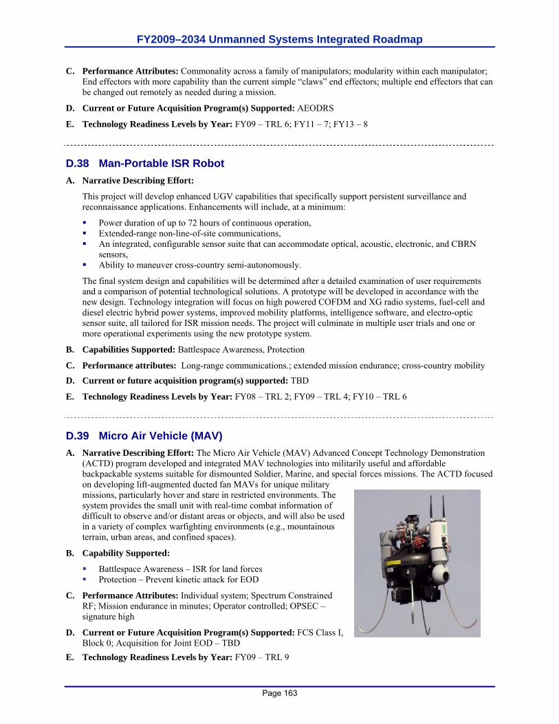
FY2009–2034 Unmanned Systems Integrated Roadmap
Page 163
C. Performance Attributes: Commonality across a family of manipulators; modularity within each manipulator; End effectors with more capability than the current simple “claws” end effectors; multiple end effectors that can be changed out remotely as needed during a mission.
D. Current or Future Acquisition Program(s) Supported: AEODRS
E. Technology Readiness Levels by Year: FY09 – TRL 6; FY11 – 7; FY13 – 8
D.38 Man-Portable ISR Robot A. Narrative Describing Effort:
This project will develop enhanced UGV capabilities that specifically support persistent surveillance and reconnaissance applications. Enhancements will include, at a minimum:
Power duration of up to 72 hours of continuous operation, Extended-range non-line-of-site communications, An integrated, configurable sensor suite that can accommodate optical, acoustic, electronic, and CBRN
sensors, Ability to maneuver cross-country semi-autonomously.
The final system design and capabilities will be determined after a detailed examination of user requirements and a comparison of potential technological solutions. A prototype will be developed in accordance with the new design. Technology integration will focus on high powered COFDM and XG radio systems, fuel-cell and diesel electric hybrid power systems, improved mobility platforms, intelligence software, and electro-optic sensor suite, all tailored for ISR mission needs. The project will culminate in multiple user trials and one or more operational experiments using the new prototype system.
B. Capabilities Supported: Battlespace Awareness, Protection
C. Performance attributes: Long-range communications.; extended mission endurance; cross-country mobility
D. Current or future acquisition program(s) supported: TBD
E. Technology Readiness Levels by Year: FY08 – TRL 2; FY09 – TRL 4; FY10 – TRL 6
D.39 Micro Air Vehicle (MAV) A. Narrative Describing Effort: The Micro Air Vehicle (MAV) Advanced Concept Technology Demonstration
(ACTD) program developed and integrated MAV technologies into militarily useful and affordable backpackable systems suitable for dismounted Soldier, Marine, and special forces missions. The ACTD focused on developing lift-augmented ducted fan MAVs for unique military missions, particularly hover and stare in restricted environments. The system provides the small unit with real-time combat information of difficult to observe and/or distant areas or objects, and will also be used in a variety of complex warfighting environments (e.g., mountainous terrain, urban areas, and confined spaces).
B. Capability Supported:
Battlespace Awareness – ISR for land forces Protection – Prevent kinetic attack for EOD
C. Performance Attributes: Individual system; Spectrum Constrained RF; Mission endurance in minutes; Operator controlled; OPSEC – signature high
D. Current or Future Acquisition Program(s) Supported: FCS Class I, Block 0; Acquisition for Joint EOD – TBD
E. Technology Readiness Levels by Year: FY09 – TRL 9
FY2009–2034 Unmanned Systems Integrated Roadmap
Page 164
D.40 Modeling and Simulation A. Narrative Describing Effort: Robotics have rapidly become a disruptive technology within the United States
military forces. Many recognize the potential of robotics/unmanned systems in military operations; yet few understand how to employ them effectively. Computer generated modeling and simulation tools are extremely valuable in an attempt to generate both operational concepts for tactics, techniques and procedures (TTP) as well as technical requirements to enable those procedures,. If conducted early on in the prototyping process (i.e., TRL 2 – 4) rather than after a prototype is considered “ready for transition,” the process of conducting repetitive, integrated simulated and live user exercises with both computer models of new and disruptive technologies with the prototypes themselves, has great potential for both speeding up and improving the design and development process, but only if the S&T community, combat developers, and end users, all actively participate, early on and continually. This is especially true with disruptive technologies like robotics/unmanned systems that have not previously been employed in combat. This program seeks to develop the modeling and simulation (M&S) tools needed to assess the impact of robotic systems on military forces.
B. Capability Supported: Force Application, Command and Control, Battlespace Awareness, Net-Centric, Building Partnerships, Protection, Logistics, Force Support, and Corporate Management and Support.
C. Performance Attributes: Accurate reflection of specific system concepts and designs from the onset; continual maturation (i.e., increased fidelity, performance, etc.); repetitive process
D. Current or Future Acquisition Program(s) Supported: Practically all OSD Unmanned Systems Roadmap-listed programs/projects could benefit from employing M&S analysis during their early development phases, e.g., “Formulation of Technology Concept or Application” (TRL 2), “Analytical & Experimental Critical Function and/or Characteristic Proof-of-Concept” (TRL 3), and “Component and/or Breadboard Validation in a Laboratory Environment” (TRL 4).
E. Technology Readiness Levels by Year: Notional: FY09 - TRL3; FY10 - TRL 4; FY11 - TRL 5; FY12 - TRL 6; FY13 - TRL 7; FY14 - TRL 8; FY15 - TRL 9. Specific TRL levels will vary by each specific M&S tool.
D.41 Multi Dimensional Mobility Robot (MDMR) A. Narrative Describing Effort: The Multi Dimensional Mobility Robot (MDMR) program will investigate using
serpentine mobility to achieve new ground robot capabilities for search and rescue in hazardous environments, such as urban rubble piles. To achieve such a degree of mobility, design concepts will address a variety of challenges including: on-board power management; situational awareness; complex terrain navigation; and system controls.
B. Capability Supported: Battlespace Awareness – Intelligence, Surveillance, and Reconnaissance
C. Performance Attributes: Individual System; Spectrum Independent – Hopping; Mission Endurance – Hours; Operator Controlled; Expanded Environmental Difficulty; Product Line Independent; OPSEC Signature – Low; Operational Control 1:1
D. Current or Future Acquisition Program(s) Supported: TBD
E. Technology Readiness Levels by Year: 2008 – TRL 6
D.42 Multi-mission Modular Unmanned Aircraft System (UAS) Chemical,
Biological, Radiological, and Nuclear (CBRN) Payloads Initiative A. Narrative Describing Effort: The Multi-mission Modular Unmanned Aircraft Systems (UAS) Payloads
Initiative program will leverage DTRA’s unique UAS and Chemical, Biological, Radiological, and Nuclear (CBRN) sensor expertise and capabilities across directorates to meet a broad set of functional area mission requirements including Combat Assessment, Nuclear Forensics, Target Area ISR, Force Protection, Weapons of Mass Destruction (WMD) Elimination and Post Intercept Assessment. The initiative will build on current DTRA CBRN sensor/UAS integration efforts including WMD Aerial Collection System (WACS), Biological
FY2009–2034 Unmanned Systems Integrated Roadmap
Page 165
Combat Assessment System (BCAS), NT Forensics and the Multi-mission CBRN Sampling Study. Initiative objectives include producing modularized CBRN sensing payloads that satisfy Warfighter CBRN requirements, eliminate multiple systems integrators, and reduce the number of unique DTRA solutions/platforms for aerial CBRN sensing.
B. Capability Supported: Battlespace Awareness: ISR Planning & Direction, Collection, Processing/Exploitation, Analysis and Production and ISR Dissemination.
C. Performance Enabled: Mission Package Product Line Independent; Real-time detection, identification, collection and tracking of CBRN materials in a threat environment.
D. Current or Future Acquisition Program(s) Supported: TBD E. Technology Readiness Levels by Year: TBD D.43 Multi-modal Human Detection A. Narrative Describing Effort: Human detection based on the integration and fusion of a number of
technologies, including acoustic, thermal, radar, ladar, visual, and multispectral sensors. Numerous detection approaches exist, depending on the environment and application. Detection from a static location is the most proven method; to detect humans from mobile robot platforms introduces more environment variables in order to perform the detection on-the-move. Change detection is another approach, which requires a baseline model of the environment. As 3D world modeling techniques from mobile robot platforms become more mature, a priori information may no longer be needed, and changes can be more easily detected and identified.
B. Capability Supported: Force Application, Battlespace Awareness C. Performance Attributes: Classification of human vs. other anomalies with certain detection and false alarm
rates. D. Current or Future Acquisition Program(s) Supported: TBD E. Technology Readiness Levels by Year: Given adequate funding, and depending on applications: FY09 - TRL
3-4; FY10 – TRL 4-5; FY11 - TRL 5-6 D.44 Nano-Flapping Air Vehicle A. Narrative Describing Effort: The Nano-Flapping Air Vehicles program will develop flapping air vehicle
technology leading to a bio-inspired flapping air vehicle with less than two-inch wingspan and gross takeoff weight of approximately 10 grams or less. Urban terrain operations require sensors that can be inserted without being detected, and that can navigate in difficult terrain. Small air vehicles that could be camouflaged or that blend into the surrounding landscape and that can navigate interiors without GPS could autonomously carry out a number of high-risk missions currently done by Warfighters.
B. Capability Supported: Force Application; Battlespace Awareness
C. Performance Attributes: Teleoperation; Individual system; Mission endurance in hours; Obstacle Avoidance; Moderate Environmental Difficulty; OPSEC – Sig Moderate
D. Current or Future Acquisition Program(s) Supported: TBD
E. Technology Readiness Levels by Year: FY09 – TRL4; FY10 – TRL5; FY11 – TRL5; FY12 – TRL6; FY13 – TRL6
D.45 Navigation
A. Narrative Describing Effort: The Autonomous Robotic Capability Suite (ARCS) program addresses a USA Engineering requirement to provide a multifunctional robotic capability using fielded small robotic systems while demonstrating system collaboration. Today’s robots cannot adaptively seek, automatically map or provide the dexterity or mobility to address complex hazards. The overarching goal of the ARCS effort is to provide intelligent, mission centric payloads that transform existing robots into effective threat identification,
FY2009–2034 Unmanned Systems Integrated Roadmap
Page 166
characterization, and mapping systems. The ARCS program will develop plug and play payloads for multiple missions (e.g., countermine, chemical, biological, radiological, nuclear (CBRN), improvised explosive device (IED), and human detection). The system will seek and show threats in a real-time map that effectively communicates a safe route. The result will be robotic systems that are more effective at finding and localizing threats.
B. Capability Supported: This applies to command and control, force support, & protection.
Support of JGR Technology Matrix:
1. Interface Technologies: Organic tasking tools such as hand-held controllers for proximal interaction on the move to task manage and control multiple unmanned aircraft systems (UAS) and UGVs to collaboratively conduct specified missions.
2. Autonomous Technologies: Provides small-scale, inexpensive autonomy payloads imbedded with sensor based tactical behaviors to achieve collaborative threat seeking capabilities.
3. Sensors-Perception for UAS and UGV navigation, collaborative behaviors and explosive hazard detection.
4. Seamless positioning for UAS and UGV navigation, such that UAS and UGVs can support one another in the case of communications and positioning failures
5. Path Planning for the UAS to UGV to plan and execute a path to a sensor designated point on the ground.
6. Local common operating picture tools that use common reference points and environmental features to support mission planning.
7. Cooperative behaviors to search for, detect, report and mark countermine (CM) and CBRN and explosive hazards.
8. Enhancement to the INL’s robot intelligence kernel (RIK) – a common behavior architecture for unmanned ground vehicles developed by the Department of Energy’s (DOE) INL and (b) a multi-robot mission planning and tasking architecture developed by the SPAWAR.
Interoperability: ARCS benefits from a high level of interoperability between the search UAS and the search and detect small UGVs. In addition, the program requires advanced interoperability between the unmanned systems payloads and the sensors to affect tactical behaviors. All behaviors will be developed to be portable and reconfigurable so that they can be used on multiple ground vehicles. The behaviors involved in this program have already been ported and demonstrated on 20 unique robotic systems.
Joint Interest: This experiment will bring together multi-agency advanced technologies to include:
1. Advanced countermine sensor technology developed by the NVESD, Fort Belvoir, VA.
2. Integrated marking system from SPAWAR, San Diego.
3. Adjustable autonomy behaviors for navigation, coverage from INL to enable countermine tactical behavior robots.
4. Payload development and support from Program Manager Countermine and Explosive Ordnance Disposal (PM CM&EOD), Fort Belvoir, VA.
5. Payload development from selected vendor(s).
6. Small UAS from INL with semi-autonomous capabilities and sensors.
C. Performance Attributes: Mission complexity; maneuverability; architecture unlimited; autonomous navigation; complex terrain mobility; situational awareness
D. Current or future acquisition program(s) supported: PM CM&EOD Countermine Mobility Marking Autonomy and Detection (CMMAD) project; Technology Transfer Agreements (TTA) are in draft in order to ensure that the integrated packages from the ARCS efforts are utilized by emerging Capability Description Documents (CDDs) and Capability Production Documents (CPDs). The Robotic Tool Kit Initial Capability Document (ICD) (draft) from USAIC specifically references the data and capabilities from ARCS as a developmental need for the Tool Kit concept.
Countermine Mobility Marking Autonomy and Detection (CMMAD); PM CM&EOD
FY2009–2034 Unmanned Systems Integrated Roadmap
Page 167
Autonomous Mine Detection System (AMDS) CPD; MANSCEN, Ft. Leonard-Wood Small Unmanned Ground Vehicle (SUGV) Block 1 CPD; USAIC, Ft. Benning Robotics Tool Kit ICD (Draft); USAIC, Ft. Benning
E. Technology Readiness Levels by Year: TBD
D.46 Next Generation Power Resources A. Narrative Describing Effort: Develop technologies that would provide unmanned with the enhanced, smaller
and more robust power sources. These technologies include, but are not limited to, propane fueled solid oxide fuel cells, reduced size/weight dc-dc converters, in-hub electric motors, auxiliary power units and other fuel cell technologies.
B. Capability Supported: Potentially all JCAs.
C. Performance Attributes: Environmental Difficulty, OPSEC Signature, Mission Endurance, Survivability, Speed, Maneuverability
D. Current or Future Acquisition Program(s) Supported: FCS, Wheeled Vehicle Power & Mobility ATO, HEVEA, JP-8 Reformation ATO, (Proposed) JP-8 Powered FC Reformation System, (Proposed) Fuel Cell Power, Non-Primary Power ATO, Power and Thermal Management Technologies ATO, (Proposed) Advanced Cognitive Power Mgmt., (Proposed) High Power Non-Primary Power System, (Proposed) Integrated Hybridized Power Sources & small UGVs.
E. Technology Readiness Levels by Year: TRL 7 at end of project.
D.47 Nightingale II – Integrated UAS/UGV System
A. Narrative Describing Effort: The objective of this research effort is to develop and integrate the requisite technologies, an unmanned aircraft system (UAS) and unmanned ground vehicle (UGV) systems, for medical resupply and casualty extraction/CASEVAC (being renamed by DoD to Tactical Evacuation Care) missions. Medical supplies almost always have to be transported from the air vehicle landing site to where they are needed. Additionally, casualties must be transported to the landing site from the point-of-injury. These ground transport distances, while usually not long, are often dangerous and over/through complex terrain.
B. Capability Supported: Force Support, Logistics, Battlespace Awareness, Building Partnerships, Force Application, Logistics and Protection
C. Performance Attributes: Medical Resupply; Casualty Extraction and short-range Evacuation; Logistics Delivery; Contaminated Remains Recovery; Tactical Reconnaissance/Surveillance missions; Autonomous UAS and UGV mission planning; Autonomous UAS takeoff and transit (including collision avoidance and obstacle avoidance); autonomous landing site selection and landing; requisite all weather, day/night sensors; C2 with medical personnel; Autonomous UAS flight control systems; UAS integration with a closed-loop critical care capability (e.g., Life Support for Trauma and Transport); Autonomous UGV operations over/in complex terrain; UAS/UGV collaborative operations/teaming; UAS/UGV sensing and autonomous perception
D. Current or Future Acquisition Program(s) Supported: Future Combat System, Navy Maritime Future Forces 2050, UAS for Air Cargo Delivery, USSOCOM Autonomous Expeditionary Support Program (AESP), Battlefield Casualty Extraction Robot Project, The Combat Medic UAS System for Resupply and Evacuation, and the Autonomous CASEVAC (to be renamed Tactical Evacuation Care) Enroute Care System projects.
E. Technology Readiness Levels by Year: FY09 - TRL 4; FY10 - TRL 5; FY11 - TRL 5; FY12 - TRL 6; FY12 - TRL 6; FY13 - TRL 7; FY14 - TRL 7

FY2009–2034 Unmanned Systems Integrated Roadmap
Page 168
D.48 Non-Radio Frequency (RF) Communications A. Narrative Describing Effort: Develop a robust wireless communication system for UGV’s that utilizes
infrared and ultraviolet (UV) free space optical technologies which are much less susceptible to electromagnetic interference and frequency deconfliction issues.
B. Capability Supported: Protection, Logistics, Battlespace Awareness, Force Application.
C. Performance Attributes: Robust performance in environments with EMI; Robust LOS and NLOS performance in urban and rural environments out to 1 km; Specific performance attributes will vary by system but for most applications will include: high data rates (<3 Mb/s), low-latency (<200 ms) video and command and control data transmission including time for encoding and decoding digital video and encryption/decryption; secure transmission of classified and unclassified data.
D. Current or Future Acquisition Program(s) Supported: MTRS, AEODRS
E. Technology Readiness Levels by Year: FY09 - TRL 3
D.49 Opportunistic Communications A. Narrative Describing Effort: Develop technologies to support unmanned systems communications agility
through all communications systems. Future unmanned systems will require the ability to communicate through any and all means possible to the various entities in its sphere of influence. Humans have the ability to communicate using any available means such as telephones, digital computer messages, even visual signals (flashing lights, smoke signals). Unmanned systems will need to exploit all conventional as well as future communications systems and protocols. This will require the systems to be able to locate and exploit not only radio frequency communications, but also hardwired networks (Ethernet, telephone, etc.), and voice communication systems.
B. Capability Supported: Battlespace Awareness, Force Application, Net-centric, Protection
C. Performance Attributes: Natural Language Understanding; Multi-Frequency Communications; Autonomous Bandwidth; Fully Autonomous Situational Awareness
D. Current or Future Acquisition Program(s) Supported: TBD
E. Technology Readiness Levels by Year: 2009 – TRL 1; 2030 – TRL 6
D.50 Opportunistic Power Grazing A. Narrative Describing Effort: Develop technologies to enable robotic systems to autonomously find and
exploit sources of power during mission execution. Future unmanned systems will need to be able to maintain their systems independently of maintenance or servicing personnel during mission execution. The unmanned systems will require the ability to identify and refuel itself with the appropriate source of fuel. For some systems this will be a liquid fuel source (gas, diesel, LNG, etc.) for other systems it will be electrical power. The systems will also have to be able to perform their primary mission while refueling/recharging.
B. Capability Supported: Battlespace Awareness; Building Partnerships; Force Application; Force Support; Logistics; Protection
C. Performance Attributes: Autonomous Adaptive Tactical Behaviors; All-Weather Environmental Difficulty; OPSEC – Signature Low; Mission endurance in months; Fully Autonomous Situational Awareness
D. Current or Future Acquisition Program(s) Supported: TBD
E. Technology Readiness Levels by Year: 2009 – TRL 2; 2031 – TRL 6
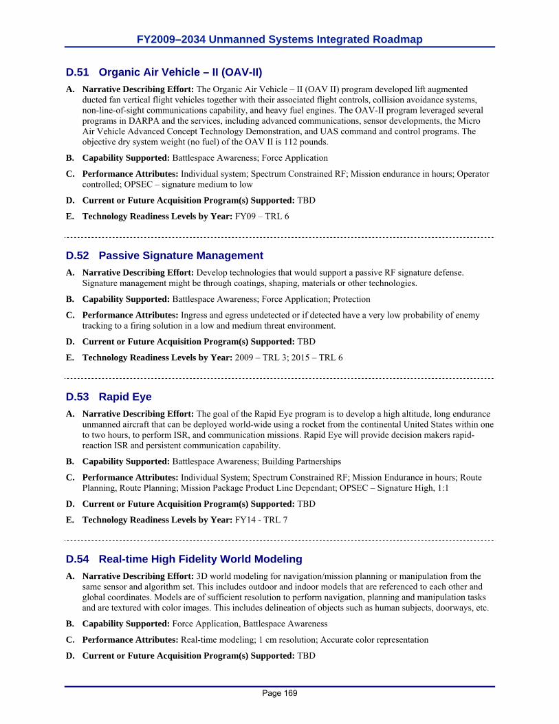
FY2009–2034 Unmanned Systems Integrated Roadmap
Page 169
D.51 Organic Air Vehicle – II (OAV-II) A. Narrative Describing Effort: The Organic Air Vehicle – II (OAV II) program developed lift augmented
ducted fan vertical flight vehicles together with their associated flight controls, collision avoidance systems, non-line-of-sight communications capability, and heavy fuel engines. The OAV-II program leveraged several programs in DARPA and the services, including advanced communications, sensor developments, the Micro Air Vehicle Advanced Concept Technology Demonstration, and UAS command and control programs. The objective dry system weight (no fuel) of the OAV II is 112 pounds.
B. Capability Supported: Battlespace Awareness; Force Application
C. Performance Attributes: Individual system; Spectrum Constrained RF; Mission endurance in hours; Operator controlled; OPSEC – signature medium to low
D. Current or Future Acquisition Program(s) Supported: TBD
E. Technology Readiness Levels by Year: FY09 – TRL 6
D.52 Passive Signature Management A. Narrative Describing Effort: Develop technologies that would support a passive RF signature defense.
Signature management might be through coatings, shaping, materials or other technologies.
B. Capability Supported: Battlespace Awareness; Force Application; Protection
C. Performance Attributes: Ingress and egress undetected or if detected have a very low probability of enemy tracking to a firing solution in a low and medium threat environment.
D. Current or Future Acquisition Program(s) Supported: TBD
E. Technology Readiness Levels by Year: 2009 – TRL 3; 2015 – TRL 6
D.53 Rapid Eye A. Narrative Describing Effort: The goal of the Rapid Eye program is to develop a high altitude, long endurance
unmanned aircraft that can be deployed world-wide using a rocket from the continental United States within one to two hours, to perform ISR, and communication missions. Rapid Eye will provide decision makers rapid-reaction ISR and persistent communication capability.
B. Capability Supported: Battlespace Awareness; Building Partnerships
C. Performance Attributes: Individual System; Spectrum Constrained RF; Mission Endurance in hours; Route Planning, Route Planning; Mission Package Product Line Dependant; OPSEC – Signature High, 1:1
D. Current or Future Acquisition Program(s) Supported: TBD
E. Technology Readiness Levels by Year: FY14 - TRL 7
D.54 Real-time High Fidelity World Modeling A. Narrative Describing Effort: 3D world modeling for navigation/mission planning or manipulation from the
same sensor and algorithm set. This includes outdoor and indoor models that are referenced to each other and global coordinates. Models are of sufficient resolution to perform navigation, planning and manipulation tasks and are textured with color images. This includes delineation of objects such as human subjects, doorways, etc.
B. Capability Supported: Force Application, Battlespace Awareness
C. Performance Attributes: Real-time modeling; 1 cm resolution; Accurate color representation
D. Current or Future Acquisition Program(s) Supported: TBD
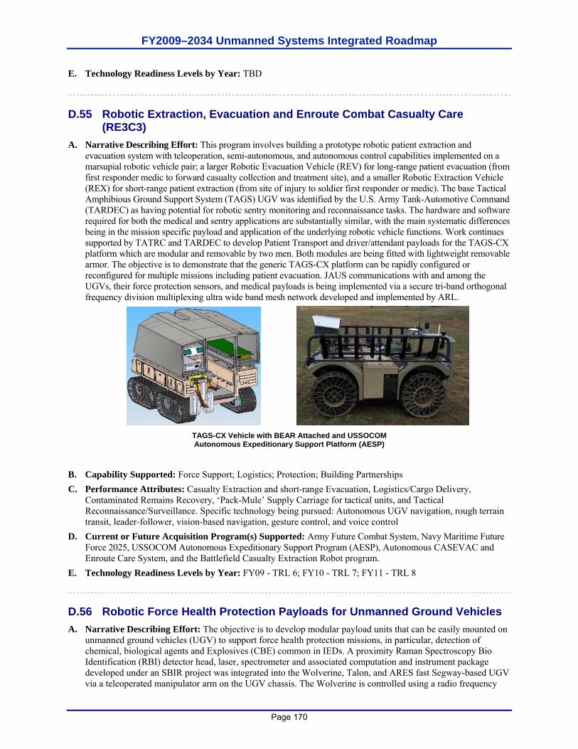
FY2009–2034 Unmanned Systems Integrated Roadmap
Page 170
E. Technology Readiness Levels by Year: TBD
D.55 Robotic Extraction, Evacuation and Enroute Combat Casualty Care
(RE3C3) A. Narrative Describing Effort: This program involves building a prototype robotic patient extraction and
evacuation system with teleoperation, semi-autonomous, and autonomous control capabilities implemented on a marsupial robotic vehicle pair; a larger Robotic Evacuation Vehicle (REV) for long-range patient evacuation (from first responder medic to forward casualty collection and treatment site), and a smaller Robotic Extraction Vehicle (REX) for short-range patient extraction (from site of injury to soldier first responder or medic). The base Tactical Amphibious Ground Support System (TAGS) UGV was identified by the U.S. Army Tank-Automotive Command (TARDEC) as having potential for robotic sentry monitoring and reconnaissance tasks. The hardware and software required for both the medical and sentry applications are substantially similar, with the main systematic differences being in the mission specific payload and application of the underlying robotic vehicle functions. Work continues supported by TATRC and TARDEC to develop Patient Transport and driver/attendant payloads for the TAGS-CX platform which are modular and removable by two men. Both modules are being fitted with lightweight removable armor. The objective is to demonstrate that the generic TAGS-CX platform can be rapidly configured or reconfigured for multiple missions including patient evacuation. JAUS communications with and among the UGVs, their force protection sensors, and medical payloads is being implemented via a secure tri-band orthogonal frequency division multiplexing ultra wide band mesh network developed and implemented by ARL.
TAGS-CX Vehicle with BEAR Attached and USSOCOM Autonomous Expeditionary Support Platform (AESP)
B. Capability Supported: Force Support; Logistics; Protection; Building Partnerships C. Performance Attributes: Casualty Extraction and short-range Evacuation, Logistics/Cargo Delivery,
Contaminated Remains Recovery, ‘Pack-Mule’ Supply Carriage for tactical units, and Tactical Reconnaissance/Surveillance. Specific technology being pursued: Autonomous UGV navigation, rough terrain transit, leader-follower, vision-based navigation, gesture control, and voice control
D. Current or Future Acquisition Program(s) Supported: Army Future Combat System, Navy Maritime Future Force 2025, USSOCOM Autonomous Expeditionary Support Program (AESP), Autonomous CASEVAC and Enroute Care System, and the Battlefield Casualty Extraction Robot program.
E. Technology Readiness Levels by Year: FY09 - TRL 6; FY10 - TRL 7; FY11 - TRL 8 D.56 Robotic Force Health Protection Payloads for Unmanned Ground Vehicles A. Narrative Describing Effort: The objective is to develop modular payload units that can be easily mounted on
unmanned ground vehicles (UGV) to support force health protection missions, in particular, detection of chemical, biological agents and Explosives (CBE) common in IEDs. A proximity Raman Spectroscopy Bio Identification (RBI) detector head, laser, spectrometer and associated computation and instrument package developed under an SBIR project was integrated into the Wolverine, Talon, and ARES fast Segway-based UGV via a teleoperated manipulator arm on the UGV chassis. The Wolverine is controlled using a radio frequency
FY2009–2034 Unmanned Systems Integrated Roadmap
Page 171
link between the robot and the operator control unit (OCU). A payload interface was written to allow control and data transmission to and from the RBI system through this wireless interface. All command and control and CBE detector payload data exchanged among the OCU, the UGV platform and the RBI payload are JAUS compliant. Currently, a smaller and improved plug-and-play standoff, fused Raman and Laser Induced Breakdown Spectroscopy (LIBS) CBE detector is being developed and evaluated. Likewise a standoff fused UV (Ultra Violet) Raman and Florence Spectroscopy CBE detector sensor head was developed for implementation on a Packbot. Initial testing of both Phase I prototype systems with bio and chemical agents and RDX explosives has been completed. In Phase II of both projects detectors are being miniaturized, ruggedized, tested with more CBE agents, and implemented on other JAUS compliant UGVs, such as BEAR or the USSOCOM AESP UGV platform.
B. Capability Supported: Protection; Force Support; Building Partnerships; Battlespace Awareness
C. Performance Attributes: CBRN standoff detection; neutralization; remediation
D. Current or Future Acquisition Program(s) Supported: Future Combat System, Maritime Future Force 2025
E. Technology Readiness Levels by Year: FY09 - TRL 6; FY10 – 6; FY11 – TRL 7; FY12 – TRL 7; FY13 – TRL 8; FY14 - TRL 8
D.57 Safety Response (Anti-tampering) A. Narrative Describing Effort: Develop technologies that would provide scaleable anti-tampering devices to
protect small, medium and large unmanned ground vehicles and robots.
B. Capability Supported: Protection.
C. Performance Attributes: Man Dependent Situational Awareness, Military Asset Protection and Robotic Non-Lethal Assets.
D. Current or Future Acquisition Program(s) Supported: TBD
E. Technology Readiness Levels by Year: FY09 - TRL 4
D.58 Safety Response A. Narrative Describing Effort: In March 2006, the Defense Safety Oversight Council Acquisition and
Technology Programs Task Force (ATP TF) initiated a study to identify the unique safety challenges of unmanned systems, especially those systems carrying and deploying weapons in a joint environment. These safety challenges significantly increase as more unmanned systems are fielded and used in the same warfighting environment. The result of the study was summarized in the DoD publication, Unmanned Systems Safety Guide for DoD Acquisition. This collaborative process considered input from dozens of experienced personnel from all services. A key mandate included looking into the future of unmanned systems. The Unmanned Systems Safety Guide for DoD Acquisition is a must-read for all unmanned systems developers.
B. Capability Supported: All capabilities supported by unmanned systems
C. Performance Attributes: Weaponization safety; software safety; power system safety
D. Current or Future Acquisition Program(s) Supported: All
E. Technology Readiness Levels by Year: N/A
D.59 Safety Response (CBRN) A. Narrative Describing Effort: Develop technologies that would enable unmanned systems to conduct survey
and monitoring missions in response to CBRN hazards. These technologies would be used to provide conventional forces with the capability to confirm or deny the presence of Weapons of Mass Destruction
FY2009–2034 Unmanned Systems Integrated Roadmap
Page 172
(WMD) in support of WMD Eliminations (WMD-E), WMD Interdiction (WMD-I) and a capability to respond to a hazardous materiel event and/or accident with no risk of initial human exposure.
B. Capability Supported: Protection
C. Performance Attributes: Characterization of atmospheres; collection of samples; provide sensor information to the operator; transport oxygen and CBRN detection/ID sensors into a facility or structure to support initial entry operations and site characterization
D. Current or Future Acquisition Program(s) Supported: Joint Nuclear, Biological, Chemical Reconnaissance System (JNBCRS), Increment II
E. Technology Readiness Levels by Year: FY09 – TRL 6
D.60 Self-Forming Unmanned Aircraft System (UAS) Communications Network A. Narrative Describing Effort: This system consists of a system of UAS that provide the Warfighter(s) in the
area of interest with an autonomous, temporary high bandwidth data chain. This system has been demonstrated during flight testing at Camp Roberts, CA in which video from a low-flying UAS was sent to an operator located beyond line-of-sight. The video was relayed across five autonomous UAS which formed a temporary high-bandwidth chain between the low-flying UAS and the operator requesting the video.
B. Capability Supported: Battlespace Awareness; Net-centric
C. Performance Attributes: Bandwidth; Teaming Within Domain
D. Current or Future Acquisition Program(s) Supported: TBD
E. Technology Readiness Levels by Year: TBD
D.61 Sense and Avoid (S&A) A. Narrative Describing Effort: Developing technologies that would support the UAS ability to maintain safe
separation or S&A other airborne vehicles or hazards in both civil and combat airspace, as well as recording and reporting obstructions as they are encountered. Other hazards in the terminal environment may include: towers, buildings, power lines or during low level flight; trees, mountains, and manmade obstacles. Efforts may include a combination of EO/IR, radar, or other technologies that would give UAS unfettered access to national, international, and combat airspace during the day and night and during various weather conditions. Efforts will include both man-in-the-loop and autonomous maneuvering. In addition to an airborne-only solution, a ground-based sense-and-avoid effort will also be explored.
B. Capability Supported: Battlespace Awareness; Force Application; Protection
C. Performance Attributes: Maintain safe separation from obstacles both in flight and on the ground
D. Current or Future Acquisition Program(s) Supported: RQ-4, MQ-1B/C, MQ-9
E. Technology Readiness Levels by Year: 2010 – TRL 6; 2015 – TRL 8
D.62 Sensors to Enable Robust Harsh-Weather Operations A. Narrative Describing Effort: Develop technologies that enable unmanned systems to operate in all weather
conditions. These technologies would include developing new or improving existing sensors, sensor packaging and operator perception and control technologies.
B. Capability Supported: Force Application; Command and Control; Battlespace Awareness
C. Performance Attributes: The ability to see and sense in all weather conditions without limiting or hindering the operator’s perception or situational awareness.
D. Current or Future Acquisition Program(s) Supported: FCS
FY2009–2034 Unmanned Systems Integrated Roadmap
Page 173
E. Technology Readiness Levels by Year: FY12 – TRL 6
D.63 Stealthy, Persistent, Perch and Stare (SP2S) A. Narrative Describing Effort: DARPA’s Stealthy, Persistent, Perch and Stare (SP2S) program is developing
the technology to enable an entirely new generation of perch-and-stare micro air vehicles capable of flying to difficult targets, landing on and securing to a “perch” position, conducting sustained, perch-and-stare surveillance missions, and then re-launching from its perch and returning to its home base.
The key technical challenges to be developed and integrated in the micro air vehicle include: (1) multifunctional materials that integrate the SP2S airframe structure with the power supply and transmit/receive antennas; (2) advanced aerodynamics and control systems, including auto-land and auto-home functions; (3) perch-and-grip technology; (4) microminiature pan/tilt/zoom EO cameras; (5) autonomous image capture; and (6) data link communications relay capability with multiple digital channels that enables beyond-line-of-sight communications, with data/video encryption.
B. Capability Supported: Battlespace Awareness; Force Application; Command & Control
C. Performance Attributes: Teaming within Domain; RF-based; Mission endurance: hours to days ; FalconView-based route planning by operator; Operation in difficult environments; Mission package single-vendor; Low weight; back-packable; on-demand ISR; Operational control: 1 operator to many operators, within the domain
D. Current or Future Acquisition Program(s) Supported: TBD
E. Technology Readiness Levels by Year: FY08 – TRL 4; FY09 – TRL 7
D.64 Super Dexterity A. Narrative Describing Effort: Manipulator and end effectors based on polymer muscle technology.
B. Capability Supported: Protection; Battlespace Awareness; Building Partnerships
C. Performance Attributes: Manipulator/end effector dexterity and tactility much greater than that of a human; Serpentine capability; Zero latency when being teleoperated.
D. Current or Future Acquisition Program(s) Supported: TBD
E. Technology Readiness Levels by Year: FY09 - TRL 3
D.65 Tactical Amphibious Ground Support System (TAGS) A. Narrative Describing Effort: TAGS-CX was developed as a MULE surrogate robotic platform to demonstrate
mission reconfiguration potential and applicable technologies for a 6000 pound robot capable of maneuvering over complex terrains.
B. Capability Supported: Battlespace Awareness; Force Application; Force Protection; Logistics
C. Performance Attributes: Applies to survivability, limited environmental difficulty, and mission complexity.
D. Current or Future Acquisition Program(s) Supported: TBD
D.66 Vision of the Trauma Pod A. Narrative Describing Effort: The vision of the Trauma Pod program is to develop a rapidly deployable system
permitting a remote physician to perform critical acute stabilization and/or surgical procedures in a teleoperative mode on wounded soldiers on the battlefield who might otherwise die from loss of airway, hemorrhage, or other acute injuries, such as a tension pneumothorax, before they can be transported to a combat hospital. The system would be used when the timely deployment of proper medical personnel is not possible or too risky, and the
FY2009–2034 Unmanned Systems Integrated Roadmap
Page 174
patient cannot be evacuated quickly enough to an appropriate medical facility. The program has demonstrated, for the first time, the conduct of a surgical procedure on a human phantom using only a telerobotic surgeon and robotic surgical assistants.
B. Capability Supported: Force Support
C. Performance Attributes: Autonomous mobility; mission endurance in hours; expanded environmental mobility; adaptive tactical behaviors
D. Current or Future Acquisition Program(s) Supported: TBD
E. Technology Readiness Levels by Year: FY09 – TRL 3; FY10 – TRL 3; FY11- TRL 4
D.67 Voice Control A. Narrative Describing Effort: Voice control teleoperation of a mobile robot, supplementing traditional control
via Operator Control Units (joysticks and screens). New technologies include audio pick-up through the ear canal, which blocks out much of the environmental noise. The microphone is inserted into the ear canal instead of being in front of the mouth. Voice recognition software must be tuned to the new medium.
B. Capability Supported: Force Application; Battlespace Awareness
C. Performance Attributes: Speech recognition in noisy or windy environments; teleoperation
D. Current or Future Acquisition Program(s) Supported: TBD
E. Technology Readiness Levels by Year: FY09 - TRL 7; FY10 - TRL 8; FY11 - TRL 9
D.68 Vulture A. Narrative Describing Effort: The goal of the Vulture program is to develop a high altitude, long endurance
(multi-year) unmanned aircraft to perform intelligence, surveillance, reconnaissance, and communication missions over an area of interest. Vulture would provide the responsive, affordable, retaskable and persistent on-station capability available in an aircraft, with a support footprint smaller than that of a satellite.
B. Capability Supported: Command and Control; Battlespace Awareness; Battlespace Awareness
C. Performance Attributes: Individual System; Spectrum Independent – Hopping; Mission endurance in years; Mission complexity – autonomous; Expanded Environmental Difficulty; OPSEC – Signature Low; Operational Control 1:1
D. Current or Future Acquisition Program(s) Supported: TBD
E. Technology Readiness Levels by Year: FY15 - TRL 7

FY2009–2034 Unmanned Systems Integrated Roadmap
Page 175
This page is intentionally left blank.
FY2009–2034 Unmanned Systems Integrated Roadmap
Page 176
APPENDIX E. JOINT CAPABILITY AREA (JCA) DEFINITIONS Joint Capability Areas (JCAs). Collections of like DoD capabilities functionally grouped to support capability analysis, strategy development, investment decision making, capability portfolio management, and capabilities-based force development and operational planning.
Tier 1 JCA. High-level capability category that facilitates capabilities-based planning, major trade analysis and decision-making.
Tier 2 JCA. More specific capability category within a parent Tier 1 JCA. Tier 2 JCAs provide sufficient definition to enable the identification of required capabilities.
Battlespace Awareness. The ability to understand the disposition and intentions as well as the characteristics and conditions of the operational environment that bear on national and military decision making.
Building Partnerships. The ability to set the conditions for interaction with partner, competitor, or adversary leaders, military forces, or relevant populations by developing and presenting information and conducting activities to affect their perceptions, will, behavior, and capabilities.
Command and Control. The ability to exercise authority and direction by a properly designated commander or decision maker over assigned and attached forces and resources in the accomplishment of the mission.
Corporate Management and Support. The ability to provide strategic senior level, enterprise-wide leadership, direction, coordination, and oversight through a chief management officer function.
Force Application. The ability to integrate the use of maneuver and engagement in all environments to create the effects necessary to achieve mission objectives.
Force Support. The ability to establish, develop, maintain and manage a mission ready Total Force, and provide, operate, and maintain capable installation assets across the total force to ensure needed capabilities are available to support national security.
Logistics. The ability to project and sustain a logistically ready joint force through the deliberate sharing of national and multi-national resources to effectively support operations, extend operational reach, and provide the joint force commander the freedom of action necessary to meet mission objectives.
Net-Centric. The ability to provide a framework for full human and technical connectivity and interoperability that allows all DoD users and mission partners to share the information they need, when they need it, in a form they can understand and act on with confidence, and protects information from those who should not have it.
Protection. The ability to prevent or mitigate adverse effects of attacks on personnel (combatant/non-combatant) and physical assets of the United States, allies, and friends.

FY2009–2034 Unmanned Systems Integrated Roadmap
Page 177
This page is intentionally left blank.
FY2009–2034 Unmanned Systems Integrated Roadmap
Page 178
APPENDIX F. UNMANNED SYSTEMS STANDARDS F.1 Interoperability Requirements Interoperability is the ability to operate in synergy in the execution of assigned tasks (JP1-02). Properly implemented, it can serve as a force multiplier and can simplify logistics. DoDD 5000.1 establishes the requirement to acquire systems and families of systems that are interoperable.4 DoD’s unmanned systems will need to demonstrate interoperability on a number of levels:
Among different systems of the same modality. The Army’s OneSystem common ground control station (GCS) for its MQ-5 Hunter, RQ-7 Shadow, and MQ-1 Warrior UAS is an example of this level of existing interoperability.
Among systems of different modalities. The planned ability of ground and air vehicles of the Army’s FCS to work cooperatively is an example of this level of future interoperability.
Among systems operated by different Military Departments under various concepts of operations (CONOPS) and tactics, techniques, and procedures (TTP), i.e., in joint operations. An example of this is the Joint Forces Air Component Commanders’ Air Tasking Order (ATO).
Among systems operated and employed by Coalition/Allied Militaries under the governance of various concepts of employment (CONEMP), TTPs, i.e., in multi-national combined operations, or NATO Standardization Agreements (STANAG). An example of this is the in- development NATO Joint Air Power Competence Centre’s “Guidance on Employment Principles for Unmanned Aircraft Systems (UAS) in NATO” CONEMP, which will be NATO’s version of the DoD’s Joint UAS CONOPS document.
Among military systems and systems operated by other entities in a common environment. The ability of military UAS to share the National Airspace System (NAS) and international airspace with commercial airliners and general aviation is an example of this level of future interoperability.
Among systems operated by non-DoD organizations, allies, and coalition partners, i.e., in combined operations. The Customs and Border Protection (CBP) RQ-9 Predator Bs and the MQ-9 Reapers of the Air Force and the RQ-1 Predators of the Italian Air Force and MQ-1 Predators of the U.S. Air Force are limited (same modality, same model), existing examples of this level of interoperability.
Interoperability is achieved by buying common components, systems, and software and/or by building systems to common standards. It is most affordable when built into the DoD systems during the design and acquisition phases, and formal standards best ensure interoperability is incorporated during these phases.
F.2 Unmanned Systems Standards Standards (formal agreements for the design, manufacture, testing, and performance of technologies) are a key enabler of interoperability. PL104-1135 requires Federal organizations to adopt commercial standards where practical rather than expending its resources to create or maintain similar ones, specifically in the case of military standards. Where needed standards do
4 DoDD 5000.1, Enclosure 1, paragraph E1.10. 5 Public Law (PL) 104-113, National Technology Transfer and Advancement Act of 1995.
FY2009–2034 Unmanned Systems Integrated Roadmap
Page 179
not exist or prove insufficient, OMB Circular A-1196 directs Federal employees to work within consensus-based standards development organizations (SDOs) to create such standards. SDOs are domestic or international organizations that plan, develop, establish, or coordinate voluntary consensus standards using agreed upon procedures that define openness, consensus, balance, due process, and appeals. DoD 4120.24-M7 requires that DoD first consider using non-Government standards (NGSs), or support revising or developing a NGS to meet DoD needs, in preference to using Federal documents whenever feasible. In addition to interoperability, using standards also promotes product quality assurance, furthers DoD commercial acquisition goals, conserves DoD resources, supports the U.S. industrial base, promotes dual-use technology, and improves DoD’s mobilization capabilities.
Recognizing the relationship between interoperability and standards, the Secretary of Defense delegated responsibility to the Under Secretary for Acquisition, Technology, and Logistics, who assigned the Defense Standardization Program Office (DSPO) as the executive agent to encourage and coordinate DoD’s role in standards development and use. DSPO is the DoD representative on the Congressionally mandated Interagency Committee for Standards Policy, which is chaired by the National Institute for Standards and Technology (NIST) and consists of representatives from most Federal agencies. DoD’s unmanned community, represented by Naval Air Systems Command (NAVAIR) PMA-263, began developing UAS standards for NATO in the mid-1990s as a participant in NATO’s Planning Group 35 (PG-35). Beginning in 2002, a number of SDOs began creating committees within their ranks to address the needs of the unmanned community across the spectrum of U.S. and international, as well as military, civil, and commercial, users of unmanned systems (see gy for autonomous capabilities.). DSPO reviews and coordinates standards developed by these SDO committees for adoption by DoD.
DoD personnel are actively participating within these SDOs in the following roles to develop standards for unmanned systems:
Ensuring DoD-relevant standards are being created, Guarding against wording in standards that would be at cross purposes with DoD’s needs
(e.g., compromising DoD’s right to self-certify aircraft airworthiness), and Preventing duplication of standard-creating efforts across SDOs.
This last role is important because the practices of individual industry often provide the starting point of community-wide standards and make the participation of industry experts, which is largely voluntary, crucial in creating worthwhile standards; therefore, it becomes important to not squander industry’s voluntary support to these SDOs. Through their consensus-based processes, SDOs help protect the proprietary concerns of their commercial participants yet draw on the expertise of these participants to produce standards for the good of the unmanned community. DoD personnel should encourage and complement, not supplant, the participation of commercial industries in SDOs. Table F.1 describes the organizations with which DoD members are now involved in developing standards for unmanned systems.
The DoD unmanned community participates in standards development through three avenues:
6 Office of Management and Budget (OMB) Circular A-119, Federal Participation in the Development and Use of Voluntary Consensus Standards and in Conformity Assessment Activities, 1998. 7 DoD 4120.24-M, Defense Standardization Program Policies and Procedures.
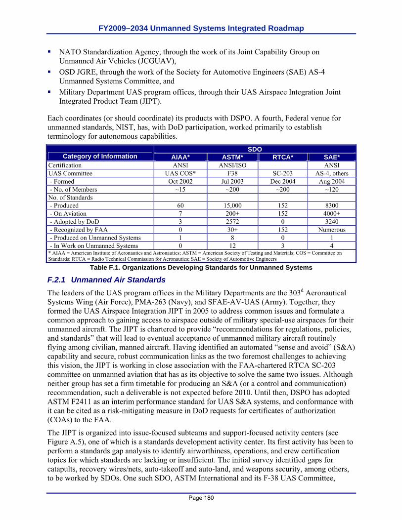
FY2009–2034 Unmanned Systems Integrated Roadmap
Page 180
NATO Standardization Agency, through the work of its Joint Capability Group on Unmanned Air Vehicles (JCGUAV),
OSD JGRE, through the work of the Society for Automotive Engineers (SAE) AS-4 Unmanned Systems Committee, and
Military Department UAS program offices, through their UAS Airspace Integration Joint Integrated Product Team (JIPT).
Each coordinates (or should coordinate) its products with DSPO. A fourth, Federal venue for unmanned standards, NIST, has, with DoD participation, worked primarily to establish terminology for autonomous capabilities.
SDO Category of Information AIAA* ASTM* RTCA* SAE*
Certification ANSI ANSI/ISO ANSI UAS Committee UAS COS* F38 SC-203 AS-4, others - Formed Oct 2002 Jul 2003 Dec 2004 Aug 2004 - No. of Members ~15 ~200 ~200 ~120 No. of Standards - Produced 60 15,000 152 8300 - On Aviation 7 200+ 152 4000+ - Adopted by DoD 3 2572 0 3240 - Recognized by FAA 0 30+ 152 Numerous - Produced on Unmanned Systems 1 8 0 1 - In Work on Unmanned Systems 0 12 3 4 * AIAA = American Institute of Aeronautics and Astronautics; ASTM = American Society of Testing and Materials; COS = Committee on Standards; RTCA = Radio Technical Commission for Aeronautics; SAE = Society of Automotive Engineers
Table F.1. Organizations Developing Standards for Unmanned Systems
F.2.1 Unmanned Air Standards The leaders of the UAS program offices in the Military Departments are the 303d Aeronautical Systems Wing (Air Force), PMA-263 (Navy), and SFAE-AV-UAS (Army). Together, they formed the UAS Airspace Integration JIPT in 2005 to address common issues and formulate a common approach to gaining access to airspace outside of military special-use airspaces for their unmanned aircraft. The JIPT is chartered to provide “recommendations for regulations, policies, and standards” that will lead to eventual acceptance of unmanned military aircraft routinely flying among civilian, manned aircraft. Having identified an automated “sense and avoid” (S&A) capability and secure, robust communication links as the two foremost challenges to achieving this vision, the JIPT is working in close association with the FAA-chartered RTCA SC-203 committee on unmanned aviation that has as its objective to solve the same two issues. Although neither group has set a firm timetable for producing an S&A (or a control and communication) recommendation, such a deliverable is not expected before 2010. Until then, DSPO has adopted ASTM F2411 as an interim performance standard for UAS S&A systems, and conformance with it can be cited as a risk-mitigating measure in DoD requests for certificates of authorization (COAs) to the FAA.
The JIPT is organized into issue-focused subteams and support-focused activity centers (see Figure A.5), one of which is a standards development activity center. Its first activity has been to perform a standards gap analysis to identify airworthiness, operations, and crew certification topics for which standards are lacking or insufficient. The initial survey identified gaps for catapults, recovery wires/nets, auto-takeoff and auto-land, and weapons security, among others, to be worked by SDOs. One such SDO, ASTM International and its F-38 UAS Committee,
FY2009–2034 Unmanned Systems Integrated Roadmap
Page 181
published a limited standards gap analysis for unmanned airworthiness in 2005 (ASTM F2501), and its recent F2585 standard for pneumatic and hydraulic catapults was adopted for DoD use by DSPO in 2006. The organization of JIPT is depicted in A.3.
In addition to the JIPT’s standards activities, PMA-263 continues to support NATO JCGUAV’s interoperability efforts in unmanned aviation. JCGUAV subsumed NATO’s three Military Department UAS-related groups (PG-35, Air Group 7, and Task Group 2) in 2006. Its major accomplishments to date have been Standardization Agreement (STANAG) 4586 for UAS message formats and data protocols, STANAG 4660 for interoperable command and control links, STANAG 4670 for training UAS operators, and STANAG 7085 for the CDL communication system, which has been mandated by OSD since 1991. It has also drafted STANAG 4671 for UAS airworthiness. Finally, the USJFCOM JUAS COE recently provided support to the OUSD (AT&L) UAS TF through review and revision of a draft Airspace Integration CONOPS. The JUAS COE also conducted a UAS National Airspace System related study for the VCJCS.
F.2.2 Unmanned Ground Standards JAUS began in 1995 as an effort by the Army’s program office for UGVs in the Aviation and Missile Research, Development and Engineering Center (AMRDEC) at Redstone Arsenal to establish a common set of message formats and data protocols for UGVs made by various manufacturers. Deciding to convert JAUS to an international industry standard, the program office approached the SAE, an SDO with robotics experience, which established the AS-4 Unmanned Systems Committee in August 2004. AS-4 has three subcommittees focused on requirements, capabilities, and interfaces and an experimental task group to test its recommended formats and protocols before formally implementing them. It plans to complete its conversion of JAUS and issue it as an SAE standard during third quarter FY2009. Although AS-4 is open to its members’ creating standards on other aspects of unmanned systems beyond message formats and data protocols for UGVs, much of this broader work is now being undertaken by other UAS-related SDOs. STANAG 4586 is unmanned aviation’s counterpart to JAUS.
F.2.3 Unmanned Maritime Standards The Navy’s Program Executive Officer of Littoral and Mine Warfare (PEO(LMW)) formally adopted JAUS message formats and data protocols for use with its unmanned undersea, surface, and ground vehicles in 2005. Working through SAE AS-4, the Naval Undersea Warfare Center (NUWC) has been expanding JAUS to serve the UMS community. It has found only 21 percent of UMS message formats to be directly compatible with the formats of JAUS, with the high percentage of new formats needed possibly due to the operation of UMSs in three dimensions versus the two dimensions of UGVs, for which JAUS was developed.
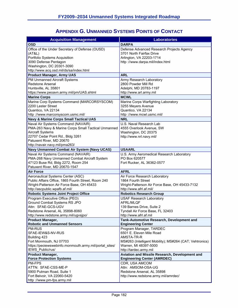
FY2009–2034 Unmanned Systems Integrated Roadmap
Page 182
APPENDIX G. UNMANNED SYSTEMS POINTS OF CONTACT Acquisition Management Laboratories
OSD DARPA Office of the Under Secretary of Defense (OUSD) (AT&L) Portfolio Systems Acquisition 3090 Defense Pentagon Washington, DC 20301-3090 http://www.acq.osd.mil/ds/sa/index.html
Defense Advanced Research Projects Agency 3701 North Fairfax Drive Arlington, VA 22203-1714 http ://www.darpa.mil/index.html
Product Manager, Army UAS ARL PM Unmanned Aircraft Systems Redstone Arsenal Huntsville, AL 35801 https://www.peoavn.army.mil/pm/UAS.shtml
Army Research Laboratory 2800 Powder Mill Rd Adelphi, MD 20783-1197 http://www.arl.army.mil
Marine Corps MCWL Marine Corp Systems Command (MARCORSYSCOM) 2200 Lester Street Quantico, VA 22134 http ://www.marcorsyscom.usmc.mil/
Marine Corps Warfighting Laboratory 3255 Meyers Avenue Quantico, VA 22134 http ://www.mcwl.usmc.mil/
Navy & Marine Corps Small Tactical UAS NRL Naval Air Systems Command (NAVAIR) PMA-263 Navy & Marine Corps Small Tactical Unmanned Aircraft Systems 22707 Cedar Point Rd., Bldg 3261 Patuxent River, MD 20670 http://navair.navy.mil/pma263/
U.S. Naval Research Lab 4555 Overlook Avenue, SW Washington, DC 20375 http://www.nrl.navy.mil/
Navy Unmanned Combat Air System (Navy UCAS) USAARL Naval Air Systems Command (NAVAIR) PMA-268 Navy Unmanned Combat Aircraft System 47123 Buse Rd, Bldg 2272, Room 254 Patuxent River, MD 20670-1547
U.S. Army Aeromedical Research Laboratory PO Box 620577 Fort Rucker, AL 36362-0577
Air Force AFRL Aeronautical Systems Center (ASC) Public Affairs Office, 1865 Fourth Street, Room 240 Wright-Patterson Air Force Base, OH 45433 http://ascpublic.wpafb.af.mil/
Air Force Research Laboratory 1864 Fourth Street Wright-Patterson Air Force Base, OH 45433-7132 http://www.afrl.af.mil/
Robotic Systems Joint Project Office Robotics Research Group Program Executive Office (PEO) Ground Combat Systems RS JPO Attn: SFAE-GCS-UGV Redstone Arsenal, AL 35898-8060 http://www.redstone.army.mil/ugvsjpo/
USAF Research Laboratory AFRL/MLQF 139 Barnes Drive, Suite 2 Tyndall Air Force Base, FL 32403 http://www.afrl.af.mil
Product Manager, Robotic and Unmanned Sensors
Tank-Automotive Research, Development and Engineering Center
PM-RUS SFAE-IEW&S-NV-RUS Building 423 Fort Monmouth, NJ 07703 https://peoiewswebinfo.monmouth.army.mil/portal_sites/ IEWS_Public/rus/
Program Manager, TARDEC 6501 E. Eleven Mile Road AMSTA-TR-R MS#263 (Intelligent Mobility); MS#264 (CAT; Vehtronics) Warren, MI 48397-5000 http://tardec.army.mil
Product Manager, Force Protection Systems
Aviation and Missile Research, Development and Engineering Center (AMRDEC)
PM-FPS ATTN: SFAE-CSS-ME-P 5900 Putman Road, Suite 1 Fort Belvoir, VA 22060-5420 http ://www.pm-fps.army.mil
CDR, USA AMCOM Attn: AMSOM-OSA-UG Redstone Arsenal, AL 35898 http://www.redstone.army.mil/amrdec/
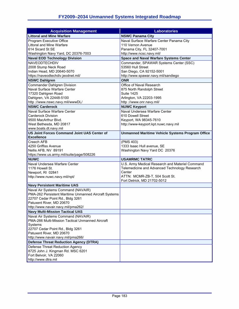
FY2009–2034 Unmanned Systems Integrated Roadmap
Page 183
Acquisition Management Laboratories Littoral and Mine Warfare NSWC Panama City Program Executive Office Littoral and Mine Warfare 614 Sicard St SE Washington Navy Yard, DC 20376-7003
Naval Surface Warfare Center Panama City 110 Vernon Avenue Panama City, FL 32407-7001 http://www.ncsc.navy.mil/
Naval EOD Technology Division Space and Naval Warfare Systems Center NAVEODTECHDIV 2008 Stump Neck Road Indian Head, MD 20640-5070 https://naveodtechdiv.jeodnet.mil/
Commander, SPAWAR Systems Center (SSC) 53560 Hull Street San Diego, CA 92152-5001 http://www.spawar.navy.mil/sandiego
NSWC Dahlgren ONR Commander Dahlgren Division Naval Surface Warfare Center 17320 Dahlgren Road Dahlgren, VA 22448-5100 http ://www.nswc.navy.mil/wwwDL/
Office of Naval Research 875 North Randolph Street Suite 1425 Arlington, VA 22203-1995 http ://www.onr.navy.mil/
NSWC Carderock NUWC Keyport Naval Surface Warfare Center Carderock Division 9500 MacArthur Blvd. West Bethesda, MD 20817 www.boats.dt.navy.mil
Naval Undersea Warfare Center 610 Dowell Street Keyport, WA 98345-7610 http://www-keyport.kpt.nuwc.navy.mil
US Joint Forces Command Joint UAS Center of Excellence
Unmanned Maritime Vehicle Systems Program Office
Creech AFB 4250 Griffiss Avenue Nellis AFB, NV 89191 https://www.us.army.mil/suite/page/508226
(PMS 403) 1333 Isaac Hull avenue, SE Washington Navy Yard DC 20376
NUWC USAMRMC TATRC Naval Undersea Warfare Center 1176 Howell St. Newport, RI 02841 http://www.nuwc.navy.mil/npt/
U.S. Army Medical Research and Materiel Command Telemedicine and Advanced Technology Research Center ATTN: MCMR-ZB-T, 504 Scott St. Fort Detrick, MD 21702-5012
Navy Persistent Maritime UAS Naval Air Systems Command (NAVAIR) PMA-262 Persistent Maritime Unmanned Aircraft Systems 22707 Cedar Point Rd., Bldg 3261 Patuxent River, MD 20670 http://www.navair.navy.mil/pma262/
Navy Multi-Mission Tactical UAS Naval Air Systems Command (NAVAIR) PMA-266 Multi-Mission Tactical Unmanned Aircraft Systems 22707 Cedar Point Rd., Bldg 3261 Patuxent River, MD 20670 http://www.navair.navy.mil/pma266/
Defense Threat Reduction Agency (DTRA) Defense Threat Reduction Agency 8725 John J. Kingman Rd. MSC 6201 Fort Belvoir, VA 22060 http://www.dtra.mil

FY2009–2034 Unmanned Systems Integrated Roadmap
Page 184
This page is intentionally left blank.
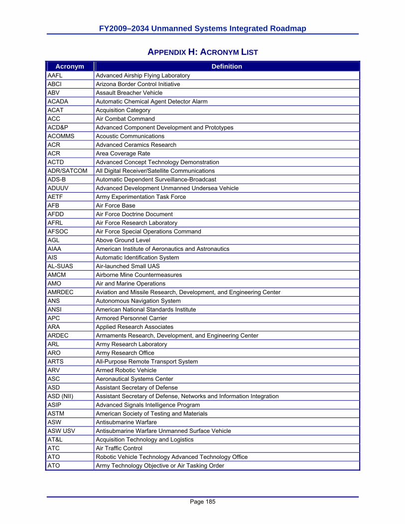
FY2009–2034 Unmanned Systems Integrated Roadmap
Page 185
APPENDIX H: ACRONYM LIST Acronym Definition
AAFL Advanced Airship Flying Laboratory ABCI Arizona Border Control Initiative ABV Assault Breacher Vehicle ACADA Automatic Chemical Agent Detector Alarm ACAT Acquisition Category ACC Air Combat Command ACD&P Advanced Component Development and Prototypes ACOMMS Acoustic Communications ACR Advanced Ceramics Research ACR Area Coverage Rate ACTD Advanced Concept Technology Demonstration ADR/SATCOM All Digital Receiver/Satellite Communications ADS-B Automatic Dependent Surveillance-Broadcast ADUUV Advanced Development Unmanned Undersea Vehicle AETF Army Experimentation Task Force AFB Air Force Base AFDD Air Force Doctrine Document AFRL Air Force Research Laboratory AFSOC Air Force Special Operations Command AGL Above Ground Level AIAA American Institute of Aeronautics and Astronautics AIS Automatic Identification System AL-SUAS Air-launched Small UAS AMCM Airborne Mine Countermeasures AMO Air and Marine Operations AMRDEC Aviation and Missile Research, Development, and Engineering Center ANS Autonomous Navigation System ANSI American National Standards Institute APC Armored Personnel Carrier ARA Applied Research Associates ARDEC Armaments Research, Development, and Engineering Center ARL Army Research Laboratory ARO Army Research Office ARTS All-Purpose Remote Transport System ARV Armed Robotic Vehicle ASC Aeronautical Systems Center ASD Assistant Secretary of Defense ASD (NII) Assistant Secretary of Defense, Networks and Information Integration ASIP Advanced Signals Intelligence Program ASTM American Society of Testing and Materials ASW Antisubmarine Warfare ASW USV Antisubmarine Warfare Unmanned Surface Vehicle AT&L Acquisition Technology and Logistics ATC Air Traffic Control ATO Robotic Vehicle Technology Advanced Technology Office ATO Army Technology Objective or Air Tasking Order
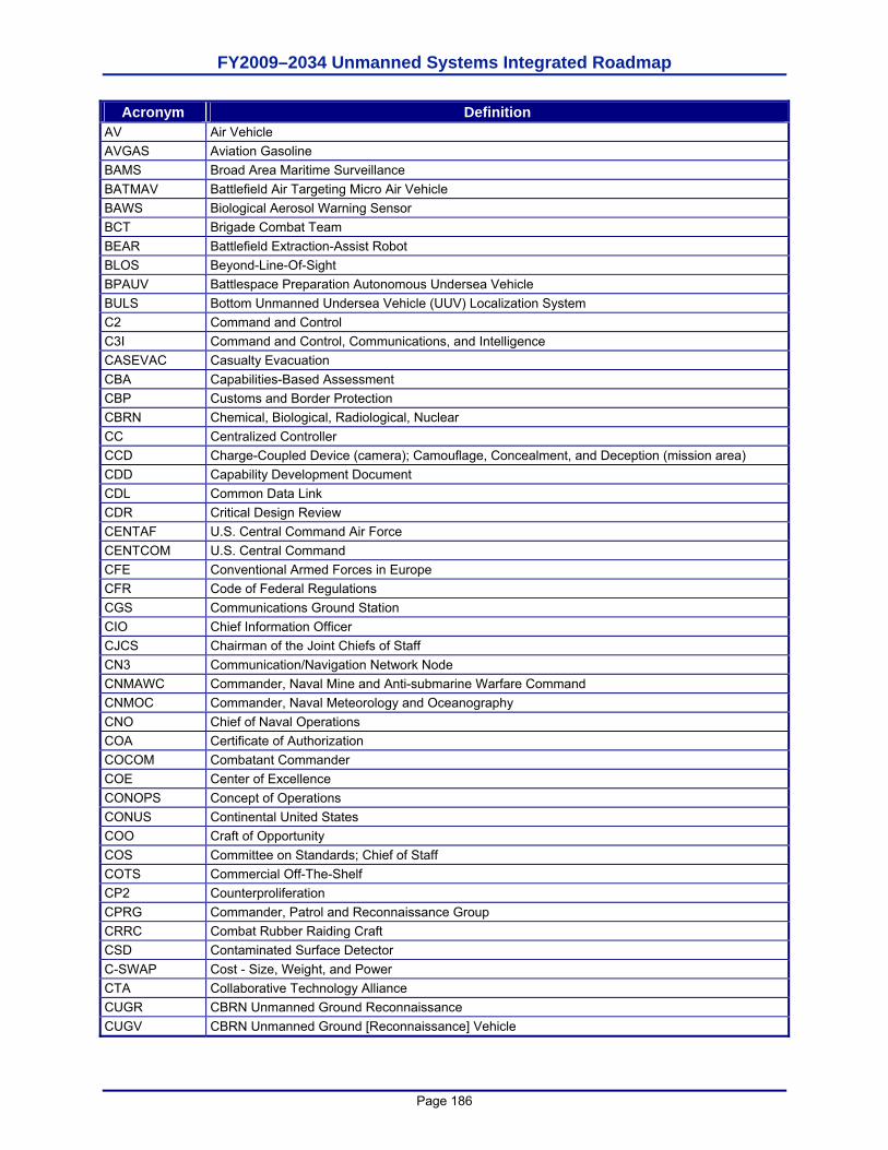
FY2009–2034 Unmanned Systems Integrated Roadmap
Page 186
Acronym Definition AV Air Vehicle AVGAS Aviation Gasoline BAMS Broad Area Maritime Surveillance BATMAV Battlefield Air Targeting Micro Air Vehicle BAWS Biological Aerosol Warning Sensor BCT Brigade Combat Team BEAR Battlefield Extraction-Assist Robot BLOS Beyond-Line-Of-Sight BPAUV Battlespace Preparation Autonomous Undersea Vehicle BULS Bottom Unmanned Undersea Vehicle (UUV) Localization System C2 Command and Control C3I Command and Control, Communications, and Intelligence CASEVAC Casualty Evacuation CBA Capabilities-Based Assessment CBP Customs and Border Protection CBRN Chemical, Biological, Radiological, Nuclear CC Centralized Controller CCD Charge-Coupled Device (camera); Camouflage, Concealment, and Deception (mission area) CDD Capability Development Document CDL Common Data Link CDR Critical Design Review CENTAF U.S. Central Command Air Force CENTCOM U.S. Central Command CFE Conventional Armed Forces in Europe CFR Code of Federal Regulations CGS Communications Ground Station CIO Chief Information Officer CJCS Chairman of the Joint Chiefs of Staff CN3 Communication/Navigation Network Node CNMAWC Commander, Naval Mine and Anti-submarine Warfare Command CNMOC Commander, Naval Meteorology and Oceanography CNO Chief of Naval Operations COA Certificate of Authorization COCOM Combatant Commander COE Center of Excellence CONOPS Concept of Operations CONUS Continental United States COO Craft of Opportunity COS Committee on Standards; Chief of Staff COTS Commercial Off-The-Shelf CP2 Counterproliferation CPRG Commander, Patrol and Reconnaissance Group CRRC Combat Rubber Raiding Craft CSD Contaminated Surface Detector C-SWAP Cost - Size, Weight, and Power CTA Collaborative Technology Alliance CUGR CBRN Unmanned Ground Reconnaissance CUGV CBRN Unmanned Ground [Reconnaissance] Vehicle
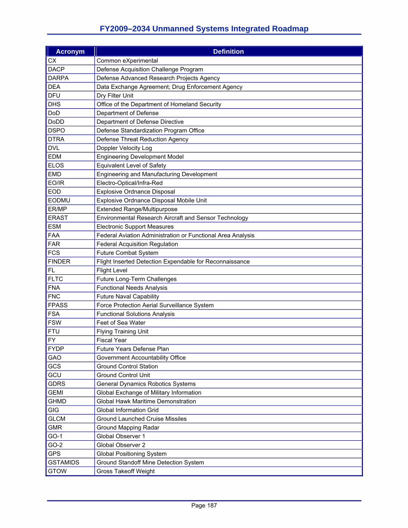
FY2009–2034 Unmanned Systems Integrated Roadmap
Page 187
Acronym Definition CX Common eXperimental DACP Defense Acquisition Challenge Program DARPA Defense Advanced Research Projects Agency DEA Data Exchange Agreement; Drug Enforcement Agency DFU Dry Filter Unit DHS Office of the Department of Homeland Security DoD Department of Defense DoDD Department of Defense Directive DSPO Defense Standardization Program Office DTRA Defense Threat Reduction Agency DVL Doppler Velocity Log EDM Engineering Development Model ELOS Equivalent Level of Safety EMD Engineering and Manufacturing Development EO/IR Electro-Optical/Infra-Red EOD Explosive Ordnance Disposal EODMU Explosive Ordnance Disposal Mobile Unit ER/MP Extended Range/Multipurpose ERAST Environmental Research Aircraft and Sensor Technology ESM Electronic Support Measures FAA Federal Aviation Administration or Functional Area Analysis FAR Federal Acquisition Regulation FCS Future Combat System FINDER Flight Inserted Detection Expendable for Reconnaissance FL Flight Level FLTC Future Long-Term Challenges FNA Functional Needs Analysis FNC Future Naval Capability FPASS Force Protection Aerial Surveillance System FSA Functional Solutions Analysis FSW Feet of Sea Water FTU Flying Training Unit FY Fiscal Year FYDP Future Years Defense Plan GAO Government Accountability Office GCS Ground Control Station GCU Ground Control Unit GDRS General Dynamics Robotics Systems GEMI Global Exchange of Military Information GHMD Global Hawk Maritime Demonstration GIG Global Information Grid GLCM Ground Launched Cruise Missiles GMR Ground Mapping Radar GO-1 Global Observer 1 GO-2 Global Observer 2 GPS Global Positioning System GSTAMIDS Ground Standoff Mine Detection System GTOW Gross Takeoff Weight
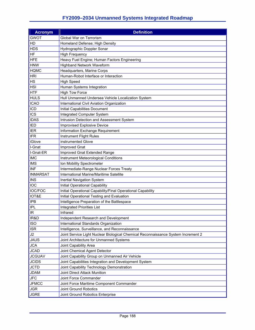
FY2009–2034 Unmanned Systems Integrated Roadmap
Page 188
Acronym Definition GWOT Global War on Terrorism HD Homeland Defense; High Density HDS Hydrographic Doppler Sonar HF High Frequency HFE Heavy Fuel Engine; Human Factors Engineering HNW Highband Network Waveform HQMC Headquarters, Marine Corps HRI Human-Robot Interface or Interaction HS High Speed HSI Human Systems Integration HTF High Tow Force HULS Hull Unmanned Undersea Vehicle Localization System ICAO International Civil Aviation Organization ICD Initial Capabilities Document ICS Integrated Computer System IDAS Intrusion Detection and Assessment System IED Improvised Explosive Device IER Information Exchange Requirement IFR Instrument Flight Rules iGlove instrumented Glove I-Gnat Improved Gnat I-Gnat-ER Improved Gnat Extended Range IMC Instrument Meteorological Conditions IMS Ion Mobility Spectrometer INF Intermediate-Range Nuclear Forces Treaty INMARSAT International Marine/Maritime Satellite INS Inertial Navigation System IOC Initial Operational Capability IOC/FOC Initial Operational Capability/Final Operational Capability IOT&E Initial Operational Testing and Evaluation IPB Intelligence Preparation of the Battlespace IPL Integrated Priorities List IR Infrared IR&D Independent Research and Development ISO International Standards Organization ISR Intelligence, Surveillance, and Reconnaissance J2 Joint Service Light Nuclear Biological Chemical Reconnaissance System Increment 2 JAUS Joint Architecture for Unmanned Systems JCA Joint Capability Area JCAD Joint Chemical Agent Detector JCGUAV Joint Capability Group on Unmanned Air Vehicle JCIDS Joint Capabilities Integration and Development System JCTD Joint Capability Technology Demonstration JDAM Joint Direct Attack Munition JFC Joint Force Commander JFMCC Joint Force Maritime Component Commander JGR Joint Ground Robotics JGRE Joint Ground Robotics Enterprise
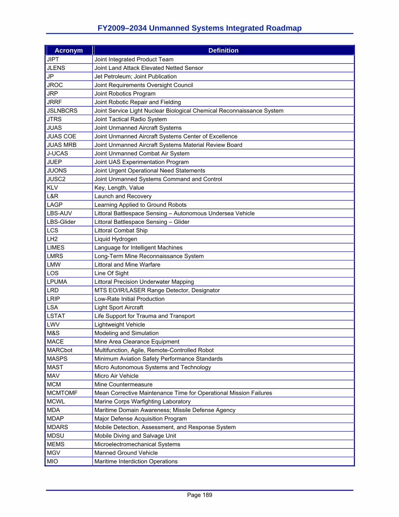
FY2009–2034 Unmanned Systems Integrated Roadmap
Page 189
Acronym Definition JIPT Joint Integrated Product Team JLENS Joint Land Attack Elevated Netted Sensor JP Jet Petroleum; Joint Publication JROC Joint Requirements Oversight Council JRP Joint Robotics Program JRRF Joint Robotic Repair and Fielding JSLNBCRS Joint Service Light Nuclear Biological Chemical Reconnaissance System JTRS Joint Tactical Radio System JUAS Joint Unmanned Aircraft Systems JUAS COE Joint Unmanned Aircraft Systems Center of Excellence JUAS MRB Joint Unmanned Aircraft Systems Material Review Board J-UCAS Joint Unmanned Combat Air System JUEP Joint UAS Experimentation Program JUONS Joint Urgent Operational Need Statements JUSC2 Joint Unmanned Systems Command and Control KLV Key, Length, Value L&R Launch and Recovery LAGP Learning Applied to Ground Robots LBS-AUV Littoral Battlespace Sensing – Autonomous Undersea Vehicle LBS-Glider Littoral Battlespace Sensing – Glider LCS Littoral Combat Ship LH2 Liquid Hydrogen LIMES Language for Intelligent Machines LMRS Long-Term Mine Reconnaissance System LMW Littoral and Mine Warfare LOS Line Of Sight LPUMA Littoral Precision Underwater Mapping LRD MTS EO/IR/LASER Range Detector, Designator LRIP Low-Rate Initial Production LSA Light Sport Aircraft LSTAT Life Support for Trauma and Transport LWV Lightweight Vehicle M&S Modeling and Simulation MACE Mine Area Clearance Equipment MARCbot Multifunction, Agile, Remote-Controlled Robot MASPS Minimum Aviation Safety Performance Standards MAST Micro Autonomous Systems and Technology MAV Micro Air Vehicle MCM Mine Countermeasure MCMTOMF Mean Corrective Maintenance Time for Operational Mission Failures MCWL Marine Corps Warfighting Laboratory MDA Maritime Domain Awareness; Missile Defense Agency MDAP Major Defense Acquisition Program MDARS Mobile Detection, Assessment, and Response System MDSU Mobile Diving and Salvage Unit MEMS Microelectromechanical Systems MGV Manned Ground Vehicle MIO Maritime Interdiction Operations
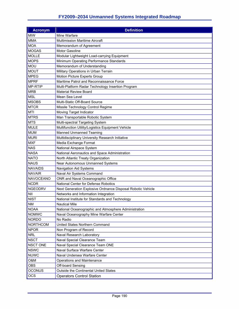
FY2009–2034 Unmanned Systems Integrated Roadmap
Page 190
Acronym Definition MIW Mine Warfare MMA Multimission Maritime Aircraft MOA Memorandum of Agreement MOGAS Motor Gasoline MOLLE Modular Lightweight Load-carrying Equipment MOPS Minimum Operating Performance Standards MOU Memorandum of Understanding MOUT Military Operations in Urban Terrain MPEG Motion Picture Experts Group MPRF Maritime Patrol and Reconnaissance Force MP-RTIP Multi-Platform Radar Technology Insertion Program MRB Material Review Board MSL Mean Sea Level MSOBS Multi-Static Off-Board Source MTCR Missile Technology Control Regime MTI Moving Target Indicator MTRS Man Transportable Robotic System MTS Multi-spectral Targeting System MULE Multifunction Utility/Logistics Equipment Vehicle MUM Manned Unmanned Teaming MURI Multidisciplinary University Research Initiative MXF Media Exchange Format NAS National Airspace System NASA National Aeronautics and Space Administration NATO North Atlantic Treaty Organization NAUS Near Autonomous Unmanned Systems NAVAIDS Navigation Aid Systems NAVAIR Naval Air Systems Command NAVOCEANO ONR and Naval Oceanographic Office NCDR National Center for Defense Robotics NGEODRV Next Generation Explosive Ordnance Disposal Robotic Vehicle NII Networks and Information Integration NIST National Institute for Standards and Technology NM Nautical Mile NOAA National Oceanographic and Atmosphere Administration NOMWC Naval Oceanography Mine Warfare Center NORDO No Radio NORTHCOM United States Northern Command NPOR Non Program of Record NRL Naval Research Laboratory NSCT Naval Special Clearance Team NSCT ONE Naval Special Clearance Team ONE NSWC Naval Surface Warfare Center NUWC Naval Undersea Warfare Center O&M Operations and Maintenance OBS Off-board Sensing OCONUS Outside the Continental United States OCS Operators Control Station
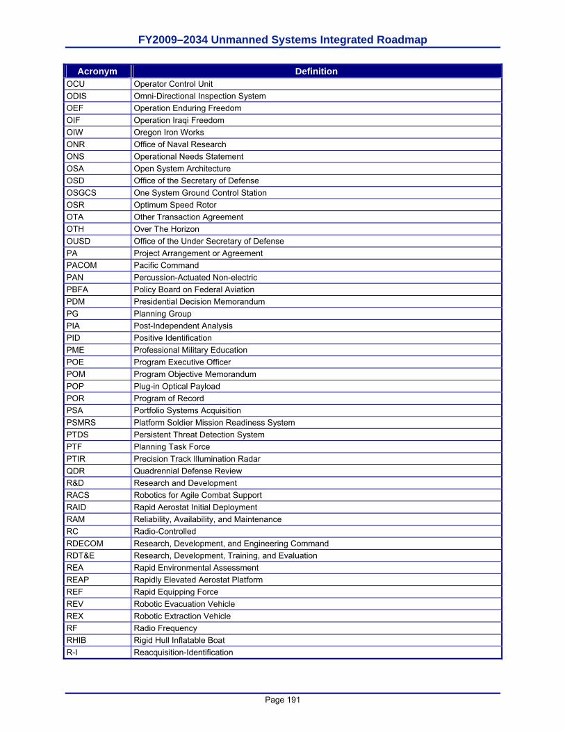
FY2009–2034 Unmanned Systems Integrated Roadmap
Page 191
Acronym Definition OCU Operator Control Unit ODIS Omni-Directional Inspection System OEF Operation Enduring Freedom OIF Operation Iraqi Freedom OIW Oregon Iron Works ONR Office of Naval Research ONS Operational Needs Statement OSA Open System Architecture OSD Office of the Secretary of Defense OSGCS One System Ground Control Station OSR Optimum Speed Rotor OTA Other Transaction Agreement OTH Over The Horizon OUSD Office of the Under Secretary of Defense PA Project Arrangement or Agreement PACOM Pacific Command PAN Percussion-Actuated Non-electric PBFA Policy Board on Federal Aviation PDM Presidential Decision Memorandum PG Planning Group PIA Post-Independent Analysis PID Positive Identification PME Professional Military Education POE Program Executive Officer POM Program Objective Memorandum POP Plug-in Optical Payload POR Program of Record PSA Portfolio Systems Acquisition PSMRS Platform Soldier Mission Readiness System PTDS Persistent Threat Detection System PTF Planning Task Force PTIR Precision Track Illumination Radar QDR Quadrennial Defense Review R&D Research and Development RACS Robotics for Agile Combat Support RAID Rapid Aerostat Initial Deployment RAM Reliability, Availability, and Maintenance RC Radio-Controlled RDECOM Research, Development, and Engineering Command RDT&E Research, Development, Training, and Evaluation REA Rapid Environmental Assessment REAP Rapidly Elevated Aerostat Platform REF Rapid Equipping Force REV Robotic Evacuation Vehicle REX Robotic Extraction Vehicle RF Radio Frequency RHIB Rigid Hull Inflatable Boat R-I Reacquisition-Identification
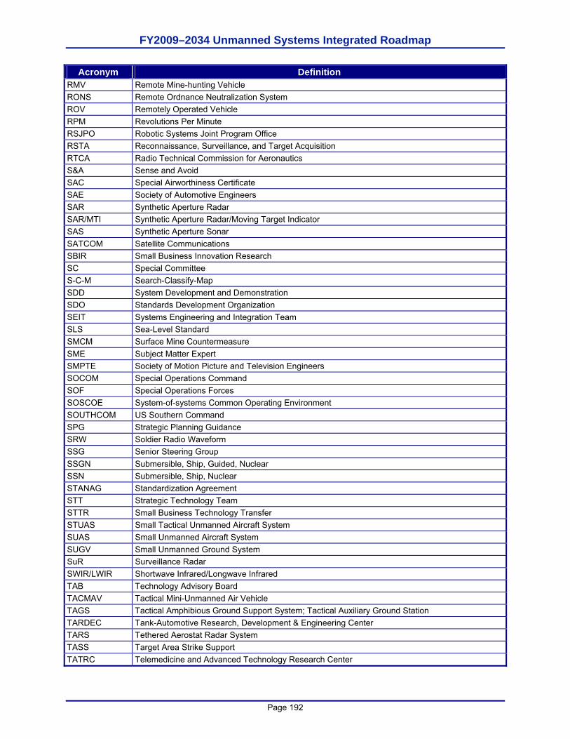
FY2009–2034 Unmanned Systems Integrated Roadmap
Page 192
Acronym Definition RMV Remote Mine-hunting Vehicle RONS Remote Ordnance Neutralization System ROV Remotely Operated Vehicle RPM Revolutions Per Minute RSJPO Robotic Systems Joint Program Office RSTA Reconnaissance, Surveillance, and Target Acquisition RTCA Radio Technical Commission for Aeronautics S&A Sense and Avoid SAC Special Airworthiness Certificate SAE Society of Automotive Engineers SAR Synthetic Aperture Radar SAR/MTI Synthetic Aperture Radar/Moving Target Indicator SAS Synthetic Aperture Sonar SATCOM Satellite Communications SBIR Small Business Innovation Research SC Special Committee S-C-M Search-Classify-Map SDD System Development and Demonstration SDO Standards Development Organization SEIT Systems Engineering and Integration Team SLS Sea-Level Standard SMCM Surface Mine Countermeasure SME Subject Matter Expert SMPTE Society of Motion Picture and Television Engineers SOCOM Special Operations Command SOF Special Operations Forces SOSCOE System-of-systems Common Operating Environment SOUTHCOM US Southern Command SPG Strategic Planning Guidance SRW Soldier Radio Waveform SSG Senior Steering Group SSGN Submersible, Ship, Guided, Nuclear SSN Submersible, Ship, Nuclear STANAG Standardization Agreement STT Strategic Technology Team STTR Small Business Technology Transfer STUAS Small Tactical Unmanned Aircraft System SUAS Small Unmanned Aircraft System SUGV Small Unmanned Ground System SuR Surveillance Radar SWIR/LWIR Shortwave Infrared/Longwave Infrared TAB Technology Advisory Board TACMAV Tactical Mini-Unmanned Air Vehicle TAGS Tactical Amphibious Ground Support System; Tactical Auxiliary Ground Station TARDEC Tank-Automotive Research, Development & Engineering Center TARS Tethered Aerostat Radar System TASS Target Area Strike Support TATRC Telemedicine and Advanced Technology Research Center

FY2009–2034 Unmanned Systems Integrated Roadmap
Page 193
Acronym Definition TBD To Be Determined TCAS Traffic Alert and Collision Avoidance System TCDL Tactical Common Data Link TCS Tactical Control System TESS Tactical Engagement Support System TFR Temporary Flight Restrictions TRADOC Training and Doctrine Command TRL Technology Readiness Levels TSWG Technical Support Working Group TTP Tactics, Techniques, and Procedures TUAV Tactical Unmanned Air Vehicle TUGV Tactical Unmanned Ground Vehicle UAS Unmanned Aircraft System UCAS Unmanned Combat Air System UCAS-D Unmanned Combat Air System Carrier Demonstration UCAV Unmanned Combat Air Vehicle UDS Unmanned Dipping Sonar UGV Unmanned Ground Vehicle UHF Ultra-High Frequency UMS Unmanned Maritime Systems UNTIA United Nations Transparency in Armaments Resolution UOES User-Operational Evaluation System UPI PerceptOR Integration USAF United States Air Force USAMRMC U.S. Army Medical Research and Materiel Command USBL Ultra-Short Baseline USBP U.S. Border Patrol USCC Unmanned Systems Capabilities Conference USCG U.S. Coast Guard USG U.S. Government USGS U.S. Geological Survey USN United States Navy USSS Unmanned Surface Sweep System USSV Unmanned Sea Surface Vehicle USV Unmanned Surface Vehicle UTAS USV Towed Array System UUV Unmanned Undersea Vehicle UUV-N Unmanned Undersea Vehicle – Neutralization UVS Unmanned Vehicle Systems UXO Unexploded Ordnance VDOC Vienna Document 1999 VFR Visual Flight Rules VHF Very High Frequency VMC Visual Meteorological Conditions VPN Virtual Private Network VSW Very Shallow Water VTOL Vertical Take-off and Landing VTUAV VTOL Tactical Unmanned Air Vehicle

FY2009–2034 Unmanned Systems Integrated Roadmap
Page 194
Acronym Definition VUAV VTOL Unmanned Air Vehicle WA Wassenaar Arrangement WAAS Wide Area Airborne Surveillance WAS Wide Area Surveillance WLAN Wireless Local Area Network WNW Wideband Network Waveform XML Extensible Markup Language

FY2009–2034 Unmanned Systems Integrated Roadmap
Page 195
This page is intentionally left blank.

FY2009–2034 Unmanned Systems Integrated Roadmap
Page 196